

Pioneer VSXD-209 Service manual

AUDIO/VIDEO MULTI-CHANNEL RECEIVER
VSX-D209
THIS MANUAL IS APPLICABLE TO THE FOLLOWING MODEL(S) AND TYPE(S).
Type
KUXJI AC120V
KCXJI AC120V
Model
VSX-D209
Power Requirement Remarks
ORDER NO.
RRV2245
CONTENTS
1. SAFETY INFORMATION
2. EXPLODED VIEWS AND PARTS LIST
3. BLOCK DIAGRAM AND SCHEMATIC DIAGRAM
4. PCB CONNECTION DIAGRAM
5. PCB PARTS LIST
6. ADJUSTMENT
PIONEER CORPORATION 4-1, Meguro 1-chome, Meguro-ku, Tokyo 153-8654, Japan
PIONEER ELECTRONICS SERVICE, INC. P.O. Box 1760, Long Beach, CA 90801-1760, U.S.A.
PIONEER ELECTRONIC (EUROPE) N.V. Haven 1087, Keetberglaan 1, 9120 Melsele, Belgium
PIONEER ELECTRONICS ASIACENTRE PTE. LTD. 253 Alexandra Road, #04-01, Singapore 159936
c
PIONEER CORPORATION 1999
...............................................
....................................................
......................................
...............
.....
.........................
24
36
41
2
3
8
7. GENERAL INFORMATION
7.1 DISASSEMBLY
7.2 PARTS
7.2.1 IC
7.2.2 DISPLAY
8. PANEL FACILITIES AND SPECIFICATIONS
..........................................................
............................................................
.................................................
................................
............................................
.......
T – ZZK DEC. 1999 Printed in Japan
42
42
43
43
49
51
VSX-D209
1. SAFETY INFORMATION
This service manual is intended for qualified service technicians ; it is not meant for the casual do-ityourselfer. Qualified technicians have the necessary test equipment and tools, and have been trained
to properly and safely repair complex products such as those covered by this manual.
Improperly performed repairs can adversely affect the safety and reliability of the product and may
void the warranty. If you are not qualified to perform the repair of this product properly and safely, you
should not risk trying to do so and refer the repair to a qualified service technician.
WARNING
This product contains lead in solder and certain electrical parts contain chemicals which are known to the state of California to cause
cancer, birth defects or other reproductive harm.
NOTICE
Fuse symbols (fast operating fuse) and/or (slow operating fuse) on PCB indicate that replacement parts must
be of identical designation.
Health & Safety Code Section 25249.6 – Proposition 65
REMARQUE
Les symboles de fusible (fusible de type rapide) et/ou (fusible de type lent) sur CCI indiquent que les pièces
de remplacement doivent avoir la même désignation.
(FOR USA MODEL ONLY)
1. SAFETY PRECAUTIONS
The following check should be performed for the
continued protection of the customer and service
technician.
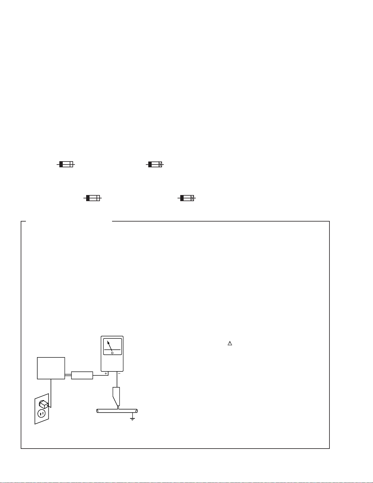
LEAKAGE CURRENT CHECK
Measure leakage current to a known earth ground (water
pipe, conduit, etc.) by connecting a leakage current tester
such as Simpson Model 229-2 or equivalent between the
earth ground and all exposed metal parts of the appliance
(input/output terminals, screwheads, metal overlays, control
shaft, etc.). Plug the AC line cord of the appliance directly
into a 120V AC 60Hz outlet and turn the AC power switch
on. Any current measured must not exceed 0.5mA.
Reading should
not be above
0.5mA
Earth
ground
Device
under
test
Also test with
plug reversed
(Using AC adapter
plug as required)
Test all
exposed metal
surfaces
Leakage
current
tester
ANY MEASUREMENTS NOT WITHIN THE LIMITS
OUTLINED ABOVE ARE INDICATIVE OF A POTENTIAL
SHOCK HAZARD AND MUST BE CORRECTED BEFORE
RETURNING THE APPLIANCE TO THE CUSTOMER.
2. PRODUCT SAFETY NOTICE
Many electrical and mechanical parts in the appliance
have special safety related characteristics. These are
often not evident from visual inspection nor the protection
afforded by them necessarily can be obtained by using
replacement components rated for voltage, wattage, etc.
Replacement parts which have these special safety
characteristics are identified in this Service Manual.
Electrical components having such features are identified
by marking with a
in this Service Manual.
The use of a substitute replacement component which does
not have the same safety characteristics as the PIONEER
recommended replacement one, shown in the parts list in
this Service Manual, may create shock, fire, or other hazards.
Product Safety is continuously under review and new
instructions are issued from time to time. For the latest
information, always consult the current PIONEER Service
Manual. A subscription to, or additional copies of, PIONEER
Service Manual may be obtained at a nominal charge from
PIONEER.
on the schematics and on the parts list
AC Leakage Test
2

2. EXPLODED VIEWS AND PARTS LIST
NOTES:• Parts marked by "NSP" are generally unavailable because they are not in our Master Spare Parts List.
2.1 PACKING
The mark found on some component parts indicates the importance of the safety factor of the part.
•
Therefore, when replacing, be sure to use parts of identical designation.
Screws adjacent to mark on the product are used for disassembly.
•
VSX-D209
1
2
4
7
12
KCXJI Type Only
13
(1) PACKING PARTS LIST
Mark No. Description Part No.
1 FM Wire Antenna ADH7004
2 AM Loop Antenna ATB7009
3 Polyethylene Bag Z21-038
NSP 4 Warranty Card See Contrast table (2)
3
NSP 7 Dry Cell Battery (R6P, AA) VEM-013
5
8
6
10
9
(0.03 × 230 × 340)
5 Remote Control Unit AXD7245
(CU-VSX166)
6 Battery Cover RZN1156
8 Left Pad AHA7275
9 Right Pad AHA7276
10 Packing Sheet AHG7069
11 Packing Case AHD7803
12 Operating Instructions ARB7202
(English)
13 Operating Instructions See Contrast table (2)
(French)
11
(2) CONTRAST TABLE
VSX-D209/KUXJI and KCXJI are constructed the same except for the following :
Part No.
Mark No. Symbol and Description VSX-D209 VSX-D209 Remarks
/KUXJI /KCXJI
NSP 4 Warranty Card ARY7023 ARY7024
13 Operating Instructions (French) Not used ARC7260
3
VSX-D209
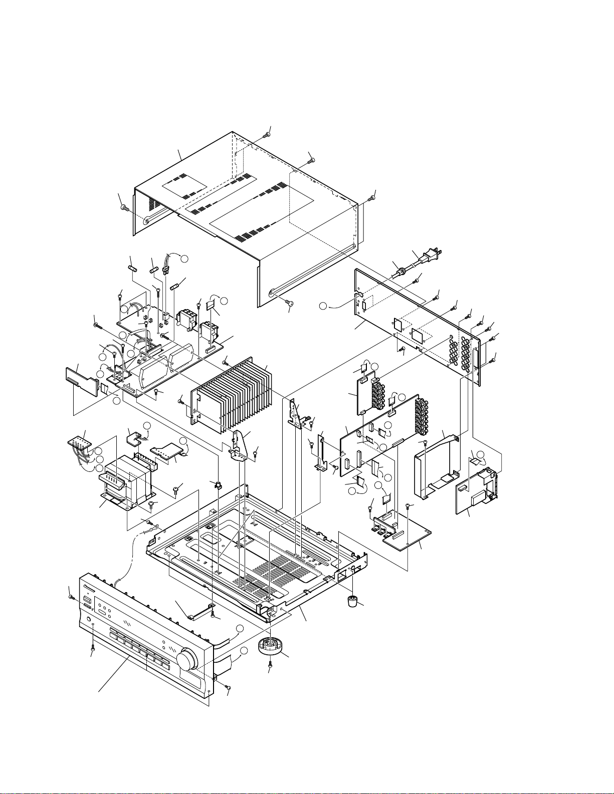
2.2 EXTERIOR SECTION
36
25
39
20
11
I
21
37
36
38
36
3
J
36
H
37
M
K
L
D
38
36
36
36
C
17
4
36
30
39
29
36
36
19
18
36
36
36
I
24
36
36
36
36
36
36
E
14
2
F
36
9
M
8
J
H
L
K
6
34
39
28
36
36
39
10
36
26
36
16
1
13
E
A
36
27
15
F
12
B
C
D
36
36
7
5
36
Accessory of
Front Panel
32
36
A
B
36
23
31
36
Refer to
"2.3 FRONT PANEL SECTION".
36
4
VSX-D209
(1) EXTERIOR SECTION PARTS LIST
Mark No. Description Part No. Mark No. Description Part No.
1 MAIN Assy AWX7455
2 VIDEO&6CH IN Assy AWX7383
NSP 3 AMP INPUT Assy AWX7382
4 AMP&PRIMARY Assy AWX7457
5 REGULATOR Assy AWX7389
6 TRANS 2 Assy AWX7391
7 FM/AM TUNER Unit AXX7046
NSP 8 TRANS 1 Assy AWX7390
NSP 9 TRANS 3 Assy AWX7392
10 Power Transformer (AC120V) ATS7263
11 Fuse (FU1 : 6.3A) REK1069
12 FFC (J31 : 30P/190 BD 60V) ADD7186
(MAIN CN102 ↔ FRONT CN402)
13 FFC (J32 : 8P/170 BD 60V) ADD7187
(MAIN CN103 ↔ FRONT CN401)
14 FFC (J33 : 12P/200 BD 60V) ADD7188
(MAIN CN104 ↔ VIDEO&6CH IN CN305)
15 FFC (J34 : 13P/80 BD 60V) ADD7189
(MAIN CN105 ↔ FM/AM TUNER CN1)
16 FFC (J35 : 17P/110 BD 60V) ADD7190
(MAIN CN106 ↔ AMP INPUT CN290)
17 FFC (J36 : 18P/80 BD 60V) ADD7191
(REGULATOR CN801 ↔ AMP&PRIMARY CN53)
18 Strain Relief CM-22C
19 AC Power Cord VDG1075
20 Fuse (FU2 : 5A) REK1067
21 Fuse (FU701 : 10A) REK1087
22 • • • • • •
NSP 23 Under Base 409 ANA7094
24 Rear Panel See Contrast table (2)
25 Bonnet Case AZN7818
26 PCB Angle ANG7253
27 Shield R3 ANG7277
28 Heat Sink Angle F ANG7251
29 Heat Sink Angle R ANG7252
NSP 30 Heat Sink 0.4 ANH7123
31 Insulator AMR7198
32 Foot Assy REC1263
33 • • • • • •
34 PCB Mold AMR2533
35 • • • • • •
36 Screw BBZ30P080FMC
37 Screw BBZ30P200FMC
38 Screw ABA7043
39 Screw FBT40P080FZK
(2) CONTRAST TABLE
VSX-D209/KUXJI and KCXJI are constructed the same except for the following :
Part No.
Mark No. Symbol and Description VSX-D209 VSX-D209 Remarks
/KUXJI /KCXJI
24 Rear Panel ANC7876 ANC7881
5
VSX-D209
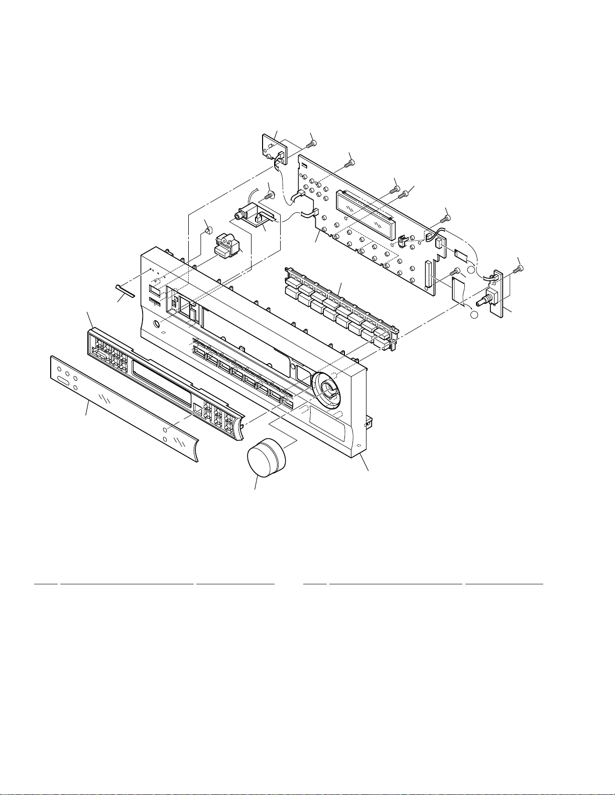
2.3 FRONT PANEL SECTION
2
16
16
11
9
13
14
17
4
7
1
10
16
16
16
16
16
A
B
3
FRONT PANEL SECTION PARTS LIST
•
Mark No. Description Part No.
1 FRONT Assy AWX7456
NSP 3 R. ENCODER Assy AWX7386
NSP 4 H.P. Assy AWX7387
2 POWER SW Assy AWX7385
5 • • • • • •
6 Volume Knob AAB7179
7 Power Button AAD7440
8 • • • • • •
9 Window AAK7709
10 F Button AAD7537
12
6
Mark No. Description Part No.
11 Sub Panel AAD7552
12 F Panel AMB7654
13 Name Plate PAM1776
14 LED Lens PNW2019
15 • • • • • •
16 Screw PPZ30P080FMC
17 Screw ABA7009
6

This page was intentionally left blank.
VSX-D209
7
1
23
VSX-D209
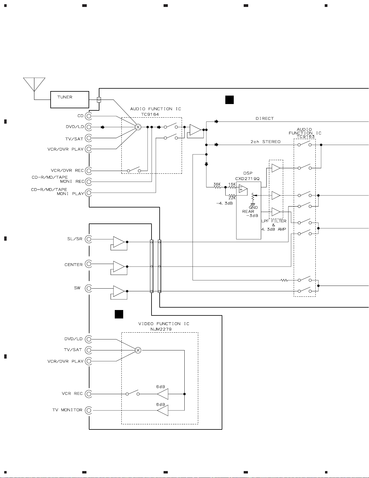
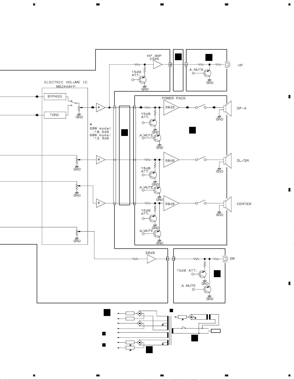
3. BLOCK DIAGRAM AND SCHEMATIC DIAGRAM
A
3.1 BLOCK DIAGRAM
4
UNIT
AXX7046
B
CN105
6
5
5
3
5
4
7
10
IC303
IC302
IC101
2
611
CN305
7
CN104
77
7
11
11
IC104
8
3
1
B
IC102
3
IC202
IC201
38
39
314
43
IC203
35
351
IC203
30
7
8
7
18
19
5
9
17
11
12
10
3
IC302
9
1
9
C
H
1
3
12
5
10
IC301
D
8
1234
5
678
VSX-D209
IC108
J43
CN102
57
IC103
Q105
17
IC105
31
57
15
4
CN106
601
1
22
Q603
A
Q601
9
11
IC106
34
57
33
10 5
24
Q653
K
3
IC601
551
4
15
C
IC602
26
I
Q551
RY751
RY753
A
B
IC107
5 7
6
36
69
+B
-B
+B
-B
FL AC
FL AC
+12V
-12V
Q701
Q702
IC801
IC802
E
POWER AMP
IC601, IC602
CN402
K
CN101
B
Q651
18
Q632
Q631
CN1041CN305
31
IC107
D701
D702
D801–D804
F
IC602
14
1
CN101
B
U+5V
IC51
RY51
T1
POWER
TRANSFORMER
Q304
D51-D54
C
RY752
Q303
T51
H
AC IN
C
D
9
5
6
7
8

1
23
VSX-D209
3.2 OVERALL WIRING CONNECTION DIAGRAM
4
CN401
491
FRONT ASSY
K
A
R.ENCODER
L
511
ASSY
(AWX7386)
(AWX7456)
CN402
AMP INPUT ASSY
A
(AWX7382)
CN290
CN291
B
CN106
CN601
CN102
CN103
B
B 1/2, B 2/2
CN104
C
MAIN ASSY
(AWX7455)
H
VIDEO&6CH IN ASSY
CN101
CN105
FM/AM
TUNER
UNIT
(AXX7046)
(AWX7383)
CN802
CN305
CN306
CN803
CN801
CN53
D
REGULATOR ASSY
F
(AWX7389)
10
1234

5
678
VSX-D209
Note : When ordering service parts, be sure to refer to "EXPLODED VIEWS and P AR TS LIST" or "PCB PARTS LIST".
POWER SW ASSY
501
471
403
J
(AWX7385)
A
551
I
H.P.
ASSY
(AWX7387)
TRANS3
E
ASSY
B
(AWX7392)
J6
J7
J3
G
J1J2
TRANS2
ASSY
(AWX7391)
J5
J4
D
851
TRANS1 ASSY
(AWX7390)
C
701
C
C 1/2, C 2/2
AMP&PRIMARY ASSY
(AWX7457)
5
D
11
6
7
8
1
23
VSX-D209
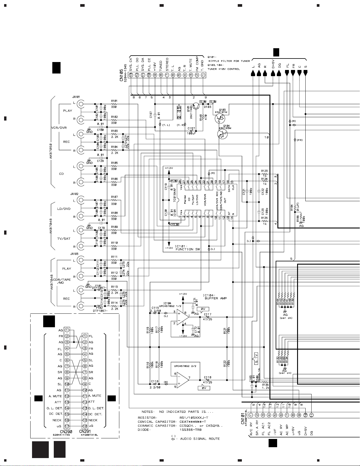
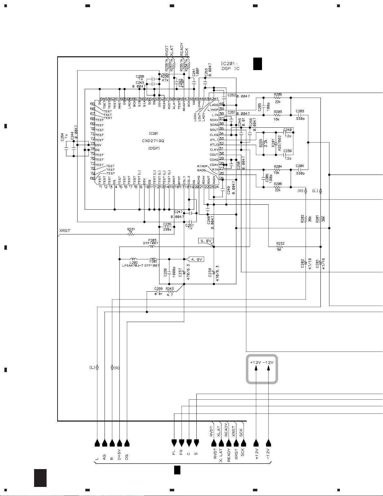
3.3 AMP INPUT and MAIN (1/2) ASSYS
4
FM/AM TUNER UNIT
A
B 1/2
B
MAIN ASSY
(AWX7455)
B 2/2
C
AMP INPUT ASSY
A
CN106
D
12
B 1/2
A
B
1234
(AWX7382)
1/2
CN601
C 1/2
F
CN802
5
B 2/2
678
VSX-D209
CN305
H
A
CN290
A
B
CN401
K
CN402
K
C
D
1/2
B
5
6
7
8
13
1
VSX-D209
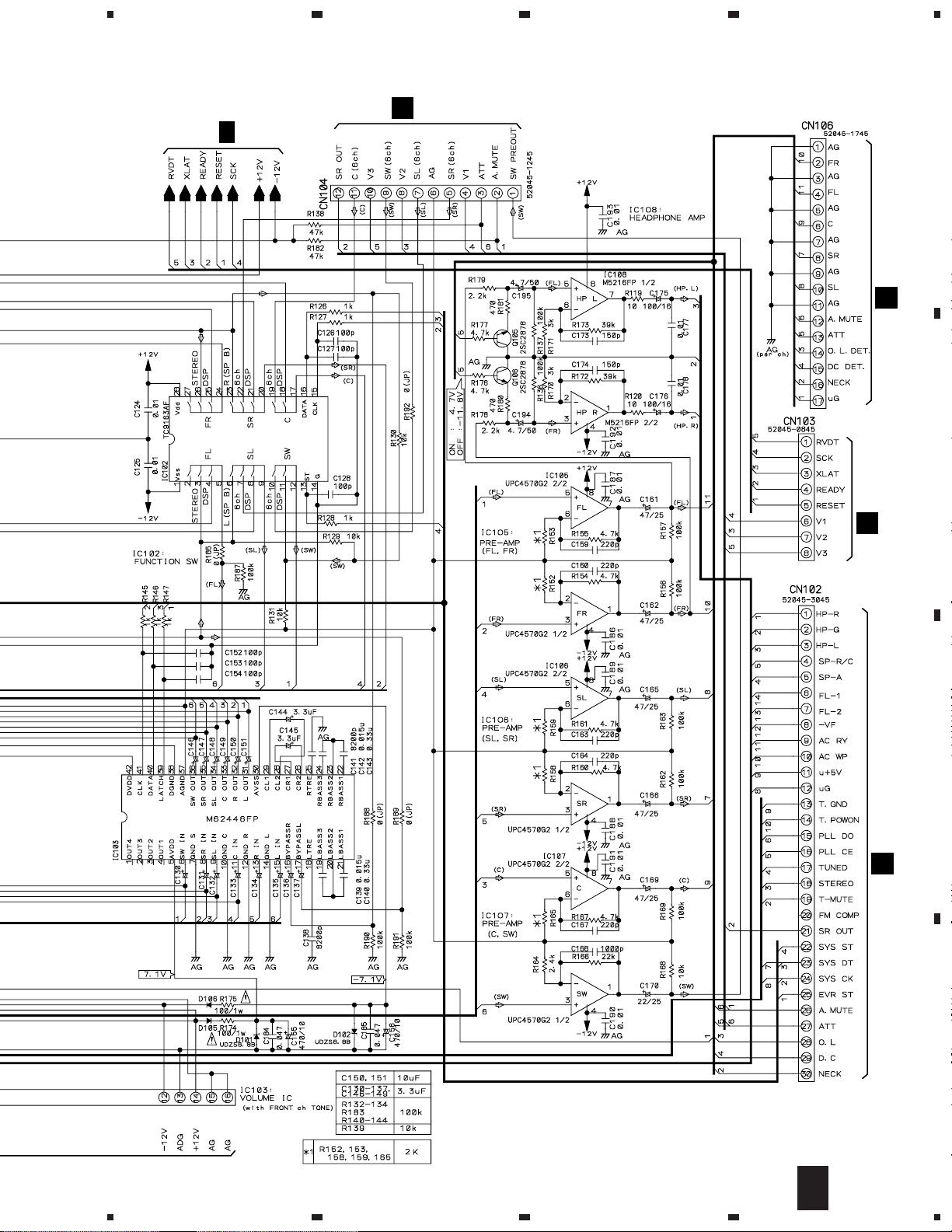
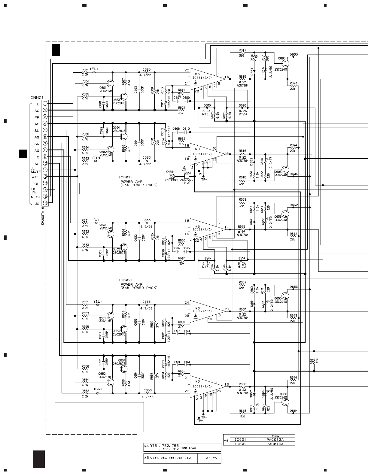
3.4 MAIN ASSY (2/2)
23
4
A
B
B 2/2
MAIN ASSY
(AWX7455)
C
D
B 1/2
14
2/2
B
1234

5
: The power supply is shown with the marked box.
678
VSX-D209
A
B
C
D
2/2
B
5
6
7
8
15
1
23
VSX-D209
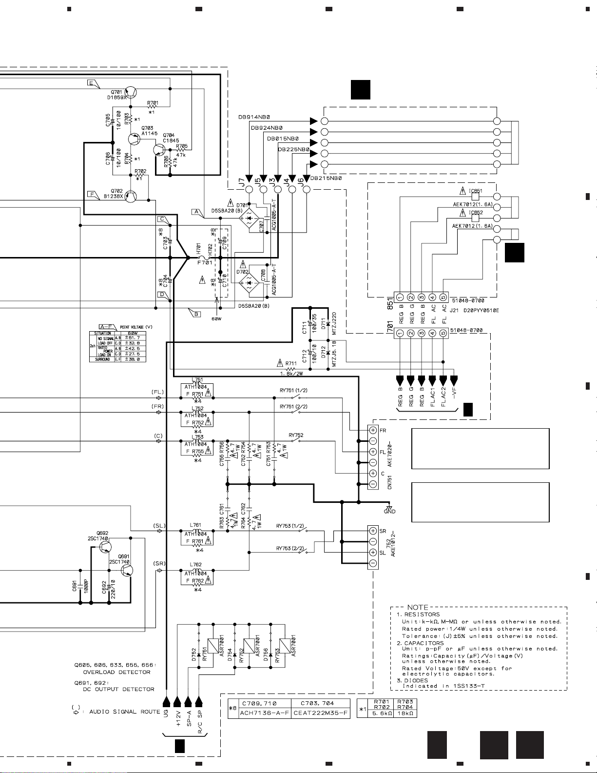
3.5 AMP&PRIMARY (1/2), TRANS2 and TRANS3 ASSYS
4
C 1/2
A
CN291
(AWX7457)
6P6P
6P6P
A
B
AMP&PRIMARY ASSY
6P6P
C
6P6P
6P6P
D
16
1/2
C
1234
5
678
VSX-D209
TRANS3 ASSY
E
(AWX7392)
POWER TRANSFORMER
A
D
REK1087
(10A)
TRANS2
ASSY
(AWX7391)
B
C 2/2
CAUTION : FOR CONTINUED PROTECTION
CAUTION : FOR CONTINUED PROTECTION
AGAINST RISK OF FIRE.
REPLACE ONLY WITH SAME TYPE
NO. 49101.6 FOR IC851 AND IC852
MFD, BY LITTELFUSE INC.
AGAINST RISK OF FIRE.
REPLACE ONLY WITH SAME TYPE
NO. 491001 FOR IC603 MFD, BY
LITTELFUSE INC.
C
D
C 2/2
5
6
7
C
1/2
D
E
8
17
 Loading...