


Pioneer VSX-924-K Quick Start Guide
Quick Start Guide
VSX-924-K
Thank you for buying this Pioneer product. This Quick Start Guide
includes instructions for basic connections and operations to allow
simple use of the receiver. For detailed descriptions of the
receiver, see the “Operating Instructions” provided on the
included CD-ROM ( ).
Muchas gracias por haber adquirido este producto de Pioneer.
Esta Guía de inicio rápido incluye instrucciones para hacer las
conexiones y operaciones básicas que le permitirán hacer un uso
sencillo del receptor. Para conocer una descripción detallada del
receptor, consulte el “Manual de instrucciones” suministrado con
el CD-ROM ( ) incluido.
དᗃ்ᗋຶҐӒᎣࠣȄԫץഁΤߟࡿࠓϲ֥ஆҐഀጤІᐈձޠ
ᇴ݃ȂѠР்߰ٻң௦ԞᏣȄԥᜱ௦ԞᏣޠၐಡᇴ݃Ȃ፝Ꭸᓎ
ߤDE.SPN)!!*ޠȶᐈձКьȷȄ
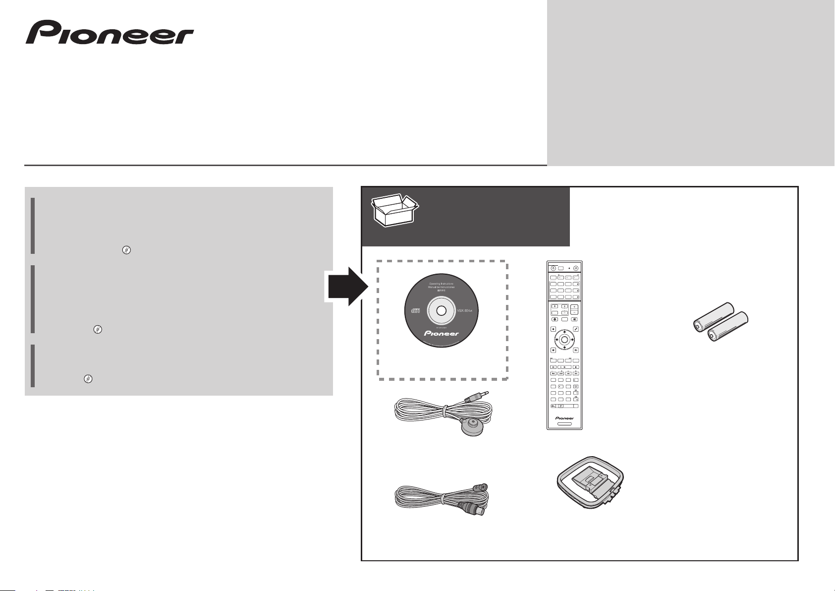
What’s in the box
Contenido de la caja
ఽᘉє၇ϲৡޑ
CD-ROM
Guía de inicio rápido
ץഁΤߟࡿࠓ
SOURCE
STANDBY/ON
ALL ZONE STBY
SUB ZONE CONTROL
RECEIVER
MAIN
Z2 Z3 HDZ
SOURCE CONTROL
HDMI
SAT
DVDBD
USBADPTROKU
NET
iPod
BT
MHL
Remote Control
ALL
TUNER
TV
CD
Mando a distancia
VOLUME
VOL
TV
INPUT
STATUS
OUT P.
AUDIO P. VIDEO P.
TOP
MENU
ENTER
HOME
MENU
LISTENING MODE
SURRAUTO
MPX
BAND PTY
PRESET TUNE
2
13
546
8079
D.ACCESS
CLRCHCH
DIMMER SLEEP
ሎᏣ
MUTE
TOOLS
MENU
RETURN
CH LV.
ADV
AUDIO
Fav
DISP
CLASS
ENTER
RCU SETUP
AAA size IEC R03 dry cell batteries x2
Pilas secas AAA, IEC R03 x 2
ୂႬԲ!y!3
AV Receiver
Receptor AV
łŗġᕘᙔᘘτᐡ
Setup microphone
Micrófono de configuración
೪ۢബջ
FM wire antenna
Antena de hilos de FM
GNጤЉጤ
RECEIVER
AM loop antenna
Antena de cuadro de AM
BNᕘםЉጤ
Power cord
Cable de alimentación
Ⴌྜጤ
Safety Brochure
Folleto de Seguridad
ԋӓКь
These quick start guide
Esta guía de inicio rápido
ץഁΤߟࡿࠓ
English
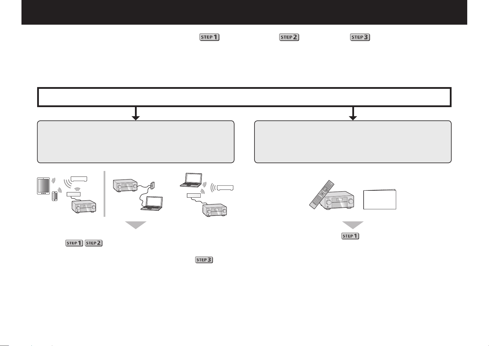
Enjoy easy multichannel playback with this unit in 3 steps:
Connecting up
→
Connection and initial setup can be performed by referring to this Quick Start Guide, but it is easier when using the
Initial setup
→
Basic playback
Wiring Navi
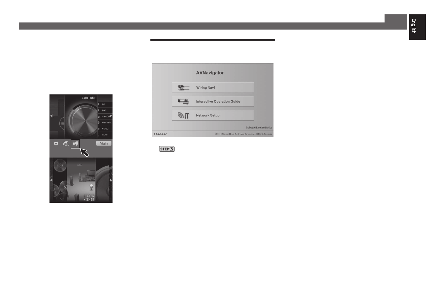
Perform connection and initial setup with either method according to the circumstances in which you are using AVNavigator.
Additionally, using the
Interactive Operation Guide
in AVNavigator allows you to learn basic operations effectively.
Connection and initial setup
Connection and initial setup following the instructions
in the “Wiring Navi” in AVNavigator
(Connection to the network is required for the initial setup.)
or
Connection and initial setup by referring to
this Quick Start Guide
Quick Start
Guide
.
in AVNavigator.
It is unnecessary to read this guide for explanations;
will be explained in the
Move on to “Using Built-in AVNavigator” in this guide.
You can use the
The contents are linked interactively with the product, allowing you
to remember them while reading, and actually use the product while
Interactive Operation Guide
becoming used to it.
Wiring Navi
in
.
.
Move on to
in this guide.
2
Using Built-in AVNavigator
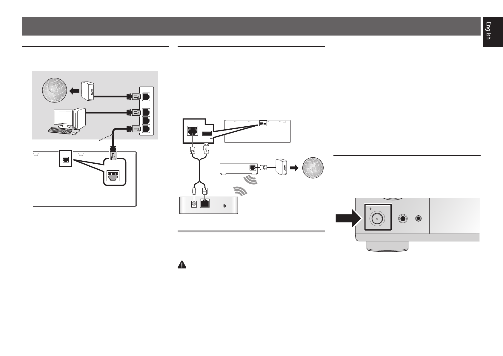
LAN
(
10/100
)
SCO
Connecting to the network through
LAN interface
Internet
Computer
LAN cable (sold separately)
LAN
Modem
)
(10/100
Router
WAN
LAN
1
2
3
Connecting to a wireless LAN
Wireless connection to the network is possible through a
wireless LAN connection. Use the separately sold AS-WL300
for connection.
• Use only the furnished accessory connecting cable.
• Certain settings are required to use a wireless LAN
converter (AS-WL300). For instructions on making these
settings, see the operating instructions included with the
wireless LAN converter (AS-WL300).
)
LAN
(10/100
DC OUTPUT
)
(10/100
LAN
DC OUTPUT
for WIRELESS LAN
(
OUTPUT 5 V
)
0.6 A MAX
Router
DC 5V WPS
Ethernet
Wireless LAN converter (AS-WL300)
for WIRELESS LAN
(
OUTPUT 5 V
)
0.6 A MAX
Modem
WAN
Internet
ask your nearest Pioneer authorized independent service
company for a replacement.
• Do not use any power cord other than the one supplied
with this unit.
• Do not use the supplied power cord for any purpose other
than that described below.
• The receiver should be disconnected by removing the
mains plug from the wall socket when not in regular use,
e.g., when on vacation.
• Make sure the blue
STANDBY/ON
u
light has gone out
before unplugging.
Plug the supplied power cord into the AC IN
1
socket on the back of the receiver.
Plug the other end into a power outlet.
2
Turning the power on
Press
computer.
Wait a few minutes after turning the power on before
performing the following operation.
STANDBY/ON
u
STANDBY/ON
to switch on the receiver and your
MCACC
PHONES
SETUP MIC
Plugging in the receiver
After connecting to a LAN, connect the power cord of the
receiver to a power outlet.
CAUTION
• Handle the power cord by the plug part. Do not pull out
the plug by tugging the cord, and never touch the power
cord when your hands are wet, as this could cause a short
circuit or electric shock. Do not place the unit, a piece of
furniture, or other object on the power cord or pinch the
cord in any other way. Never make a knot in the cord or tie
it with other cables. The power cords should be routed so
that they are not likely to be stepped on. A damaged power
cord can cause a fire or give you an electric shock. Check
the power cord once in a while. If you find it damaged,
3
Using Built-in AVNavigator (continued)
Launching the built-in AVNavigator
Operate AVNavigator by following the screen prompts of your
computer, etc.
Operating environment
• AVNavigator can be used in the following environments.
– Windows PC: Microsoft
Windows
– Mac: Mac OSX (10.7, 10.8 or 10.9)
– iPad/iPhone/iPod touch: iOS 7
– Android device: Android 4.0.4, 4.1.1, 4.1.2, 4.2, 4.2.2, 4.4.2
• Some AVNavigator functions use an Internet browser. The
following browsers are supported:
– Windows PC: Internet Explorer
– Mac/iPad/iPhone/iPod touch: Safari 6.0
– Android device: Android browser
• Depending on the computer network setting or security
setting, AVNavigator may not operate.
®
7/Windows® 8/Windows® 8.1
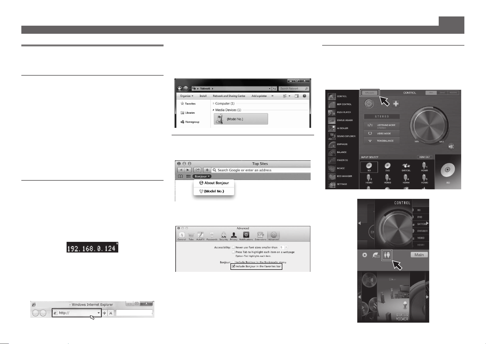
Using Windows PC
Start up Internet Explorer on your PC.
1
Open any random Internet page.
Press STATUS on the remote control and check
2
the front panel display on the receiver.
The IP address of the receiver will appear.
®
Windows® XP/Windows Vista®/
®
8, 9, 10, 11
(Example Text Display)
• With a Windows PC other than Windows XP, you can use
the following method to launch AVNavigator.
Launch Explorer and then right-click <VSX-924>
displayed in the ‘
webpage
’.
Network
’ folder, then click ‘
View device
Using Mac
Launch Safari and click <VSX-924> displayed in ‘
the Bookmarks bar.
Bonjour
• If ‘
the Favorites bar
the Safari ‘
’ is not displayed, tick the ‘
Preferences...
’ check box on the ‘
’ menu.
Include Bonjour in
Advanced
Bonjour
’ tab in
’ on
Using iPad/iPhone/iPod touch
Download a free application, iControlAV5, from the App Store.
After launching iControlAV5, follow the instructions on the
screen. After that, on the Home screen, press ‘
or the icon.
iPad
iPhone/iPod touch
AVNavigator
’
If 0.0.0.0 or 169.254.112.202 appears in the address, it indicates
that the receiver is not connected to the network. Check to
make sure that the receiver and router are properly connected.
Enter number in 2 above in the field in
3
Internet Explorer shown below and then press
the ENTER key.
(Example Input Format) 192.168.0.124
4
Using iPad
■
On an iPad, you can operate AVNavigator for iPad. Download
AVNavigator for iPad from the App Store. After launching
AVNavigator for iPad, follow the instructions on the screen.
Using Android device
Download a free application, iControlAV5, from the Google Play
Store. After launching iControlAV5, follow the instructions on
the screen. After that, on the Home screen, press the icon.
About using Wiring Navi
Wiring Navi starts when ‘
AVNavigator screen.
• When connection navigation is finished, proceed to
.
Wiring Navi
’ is pressed on the
Using Built-in AVNavigator (continued)
5
Connecting up
12 3
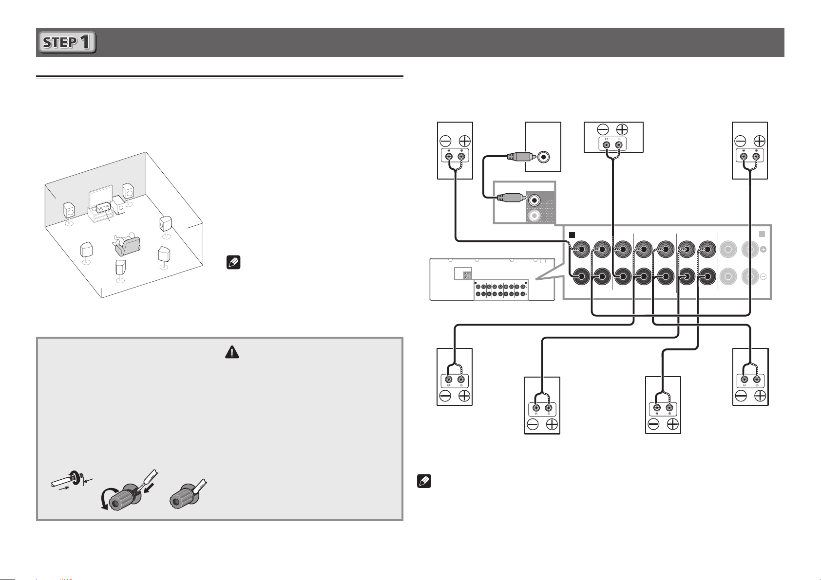
Connecting the speakers
The receiver will work with just two stereo speakers (the front speakers in the diagram) but using
at least five speakers is recommended, and a complete setup is best for surround sound.
To achieve the comfortable surround sound, install your speakers as shown below.
7.1 channel surorund system:
L
C
SL
Connecting the speaker cables
Make sure you connect the speaker on
the right to the right (R) terminal and the
speaker on the left to the left (L) terminal.
Also make sure the positive and negative
+/–
(
) terminals on the receiver match those
on the speakers.
Twist exposed wire strands together.
1
Loosen terminal and insert exposed wire.
2
Tighten terminal.
3
10 mm
R
SW
SBL
After installing the speakers, connect them as shown below.
Center
(C)
SURROUNDCENTERFRONT
SPEAKERS
SURROUND BACK / HDZONE
(
Single
Front Left
FRONT HEIGHT / WIDE /
)
RLRLRLRL
(L)
B
PRE OUT
SURROUND BACK / HDZONE
SURROUNDCENTERFRONT
SPEAKERS
Subwoofer
FRONT HEIGHT / WIDE /
B
(
)
Single
RLRLRLRL
(SW)
LINE LEVEL
INPUT
SUB
WOOFER
1
2
A
Front Right
(R)
L
– Front Left
C
– Center
R
– Front Right
SL
– Surround Left
SR
– Surround Right
SBL
SR
SBR
– Surround back Left
SBR
– Surround back Right
SW
– Subwoofer
Note
• There are also other speaker connection
PRE OUT
SUB
WOOFER
1
2
A
patterns (front height, front wide, etc.). For
details, see “Connecting your equipment”
of the operating instructions.
CAUTION
• Before making or changing
connections, switch off the power and
disconnect the power cord from the AC
outlet.
• These speaker terminals carry
HAZARDOUS LIVE
voltage. To
prevent the risk of electric shock when
connecting or disconnecting the
speaker cables, disconnect the power
cord before touching any uninsulated
parts.
Surround Right
(SR)
Surround back Right
SBR
(
)
Surround back Left
SBL
(
)
Note
• When only connecting one surround back speaker, connect it to the
(Single)
• This unit supports speakers with a nominal impedance of 6 W to 16 W.
terminals.
Surround Left
(SL)
SURROUND BACK L
6
Connecting up (continued)
A
A
VENTILATION CAUTION
When installing this unit, make sure to leave space
around the unit for ventilation to improve heat radiation
(at least 40 cm at top, 10 cm at rear
side)
W
Slots and openings in the cabinet are provided for
ventilation to ensure reliable operation of the product,
and to protect it from overheating.
hazard, the openings should never be blocked or
covered with items (such as newspapers, table-cloths,
curtains) or by operating the equipment on thick carpet
or a bed.
D3-4-2-1-7b*_A1_En
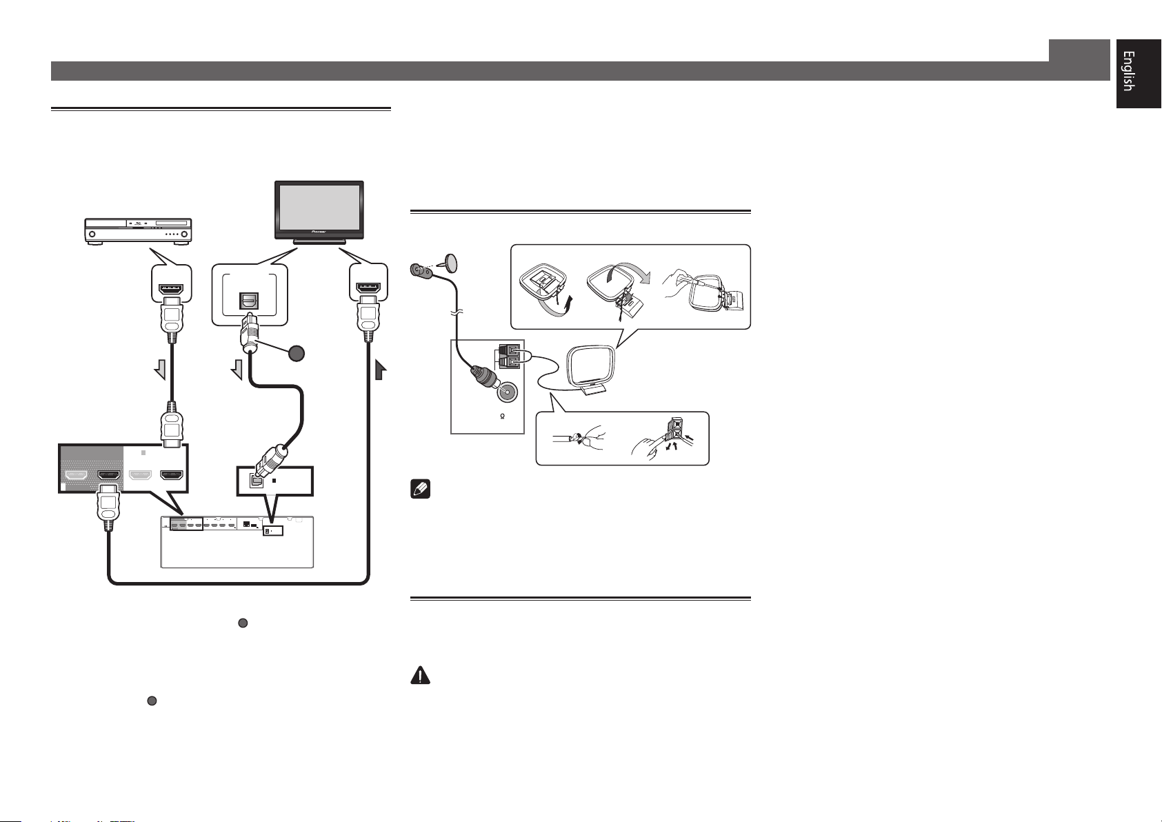
Connecting a TV and playback
components
HDMI/DVI-compatible TV
HDMI/DVI-compatible
Blu-ray DIsc player
BD IN
1
IN2IN3IN4IN /MHL
(
OUTPUT 5 V
(
)
)
SAT/CBL
0.9 A MAX
DIGITAL OUT
OPTICAL
1
IN
)
LAN
(10/100
6
DC OUTPUT
for WIRELESS LAN
(
OUTPUT 5 V
)
)
0.6 A MAX
OPTICAL
(TV)
1
IN
ASSIGNABLE
) connection is required to
ARC
HDMI OUT
OUT 2
(
HDZONE
SELECTABLE
)
(
OUT 1
CONTROL
)
BD IN
1
IN
(
)
DVD
OUT 2
OUT 1
HDMI
IN
(
HDZONE
)
(
CONTROL
)
ASSIGNABLE
-
1 6
(
DVD
SELECTABLE
• If the TV does not support the HDMI Audio Return Channel
function, optical digital cable (
listen to the TV sound over the receiver.
• If the TV supports the HDMI Audio Return Channel
function, the sound of the TV is input to the receiver via the
HDMI terminal, so there is no need to connect an optical
digital cable (
). In this case, set
to ON. For details, see “HDMI Setup” of the operating
instructions.
• Please refer to the TV’s operation manual for directions on
connections and setup for the TV.
A
OPTICAL
(TV)
ASSIGNABLE
HDMI Setup
at
HDMI IN
• With factory default settings, video from the video cable
or component cable will not be output from the HDMI
terminal. To output video, you must switch video input to
the device connected with the video cable or component
cable and set
V.CONV
to ON. For details, see “Setting the
Video options” of the operating instructions.
Connecting antennas
ab c
FM wire
antenna
5
3
AM loop antenna
AM LOOP
4
FM UNBAL
75
ANTENNA
1
2
Note
• Refer to the operating instructions in the included CD-
ROM if you wish to connect a TV or playback component
in a method other than an HDMI connection.
• Refer to the operating instructions in the included CD-
ROM for other device connections.
Plugging in the receiver
Only plug in after you have connected all your components to
this receiver, including the speakers.
CAUTION
• Handle the power cord by the plug part. Do not pull out
the plug by tugging the cord, and never touch the power
cord when your hands are wet, as this could cause a short
circuit or electric shock. Do not place the unit, a piece of
furniture, or other object on the power cord or pinch the
cord in any other way. Never make a knot in the cord or tie
it with other cables. The power cords should be routed so
that they are not likely to be stepped on. A damaged power
cord can cause a fire or give you an electric shock. Check
the power cord once in a while. If you find it damaged,
ask your nearest Pioneer authorized independent service
company for a replacement.
• Do not use any power cord other than the one supplied
with this unit.
• Do not use the supplied power cord for any purpose other
than that described below.
• The receiver should be disconnected by removing the
mains plug from the wall socket when not in regular use,
e.g., when on vacation.
• Make sure the blue
STANDBY/ON
u
light has gone out
before unplugging.
Plug the supplied power cord into the AC IN
1
socket on the back of the receiver.
Plug the other end into a power outlet.
2
, and 20 cm at each
.
ARNING
To prevent fire
7
ALL ZONE STBY
SOURCE
STANDBY/ON
MAIN
SUB ZONE CONTROL
Z2 Z3 HDZ
RECEIVER
8
Initial Setup
Before you start
Put the batteries in the remote control.
1
The batteries included with the unit are to check initial
operations; they may not last over a long period. We
recommend using alkaline batteries that have a longer life.
Switch on the receiver and your TV.
2
Switch the TV input so that it connects to the
3
receiver.
Turn the subwoofer on and turn up the volume.
4
WARNING
• Do not use or store batteries in direct sunlight or other
excessively hot place, such as inside a car or near a heater.
This can cause batteries to leak, overheat, explode or catch
fire. It can also reduce the life or performance of batteries.
CAUTION
• When inserting the batteries, make sure not to damage
the springs on the battery’s (–) terminals. This can cause
batteries to leak or overheat.
• When disposing of used batteries, please comply with
governmental regulations or environmental public
institution’s rules that apply in your country/area.
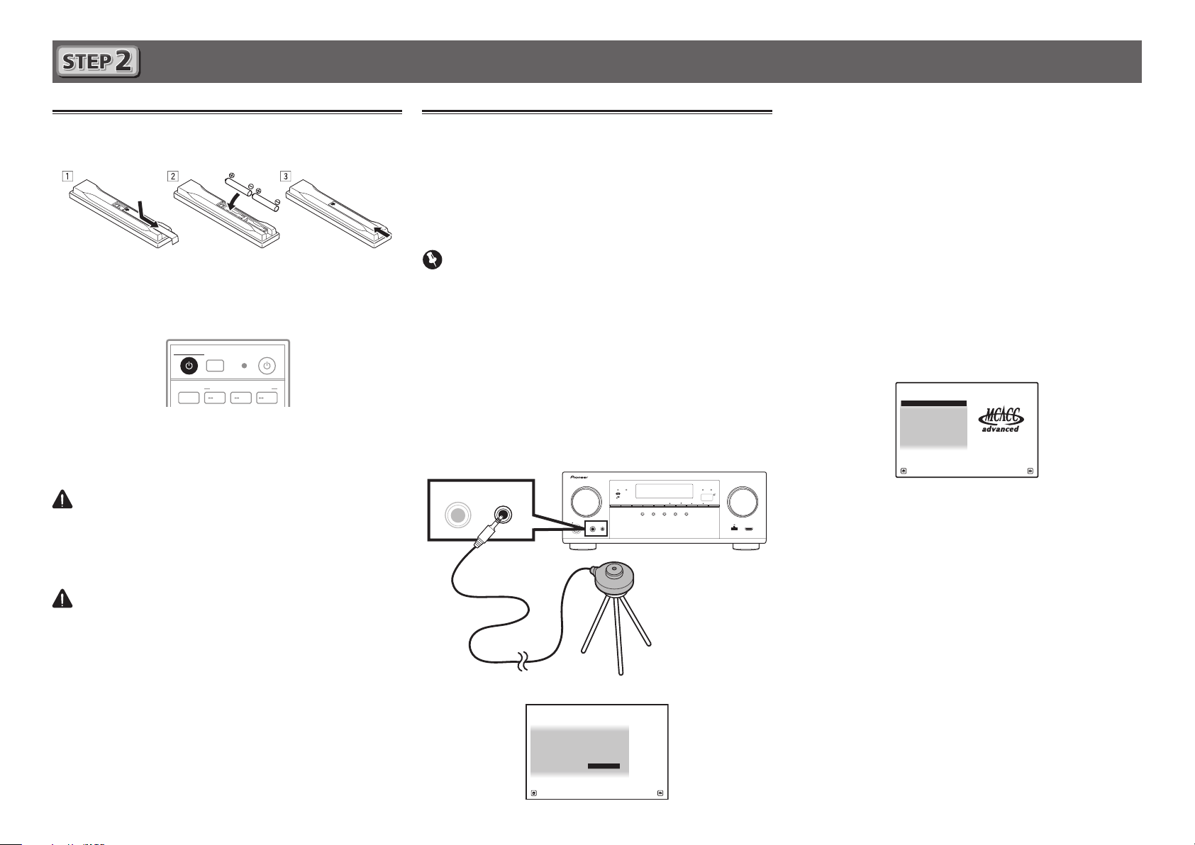
Automatically setting up for
surround sound (MCACC)
The Auto Multi-Channel ACoustic Calibration (MCACC) setup
uses the supplied setup microphone to measure and analyze
the test tone that is outputted by the speakers. This setup
enables automatic high precision measuring and settings;
utilizing it will create an optimum user listening environment.
Important
• Measure in a quiet environment.
• If you have a tripod, use it to place the microphone so that it’s
about ear level at your normal listening position. Otherwise,
place the microphone at ear level using a table or a chair.
• Accurate measurements may not be possible if there are
obstacles between the speakers and the listening position
(microphone).
• When measuring, step away from the listening position,
and operate using the remote control from the external
side of all the speakers.
Connect the supplied setup microphone.
1
ADVANCED
MCACC
PHONES
The
MCACC
SETUP MIC
Full Auto MCACC
FL OFF
SPEAKERS CONTROL – MULTI-ZONE – ON / OFFBANDTUNER EDIT TUNE PRESET ENTER
AUTO SURR/ALC/
INPUT
SELECTOR
STANDBY/ON
PHONES
STREAM DIRECT
MCACC
SETUP MIC
Microphone
Tripod
screen appears on your TV.
1a.Full Auto MCACC
A/V RECEIVER
Speaker System : Normal(SB/FH
EQ Type : ---
MCACC : M1.MEMORY 1
Measurement Type : Basic
START
Exit Return
)
ADVANCED
STANDARD
SURROUND
SURROUND
iPod iPhoneHDMI
iPod iPhone
DIRECT
CONTROLSTATUS
5V 1 A
HDMI 5 INPUT
Press MAIN RECEIVER on the remote control
2
and operate.
• When the cursor is brought to
Basic
is selected, the
Speaker Distance
Expert
allows you to automatically adjust
Speaker Setting/Channel Level
is adjusted automatically. Selecting
Wave/Acoustic Cal EQ
well.
Bring the cursor to START and press the ENTER
3
Measurement Type
and
Standing
(frequency characteristics) as
/
button.
• Automatic measuring will start.
• Measuring will take about 3 to 12 minutes.
Follow the instructions on-screen.
4
• Automatic setting is complete when the Home Menu
screen appears.
HOME MENU
1. Advanced MCACC
2. MCACC Data Check
3. Data Management
4. System Setup
5. Network Information
6. Operation Mode Setup
Reverse Phase
• If
MASTER
VOLUME
may be inverted. Check the speaker connections.
Even if the connections are correct,
A/V RECEIVER
Exit Return
is displayed, the speaker’s wiring (+ and –)
Reverse Phase
may be
displayed, depending on the speakers and the surrounding
environment. This does not affect measurements, however,
so select
Go Next
.
• If the power cuts out, the core of the speaker cable may be
in contact with the rear panel, or the (+) and (–) cores may
be touching, causing the protection circuits to activate.
Re-twist the core of the speaker cable, and connect it so
that it does not protrude from the speaker terminal.
Make sure the setup microphone is
5
disconnected.
Basic playback
2
3
5
Switch on the playback component.
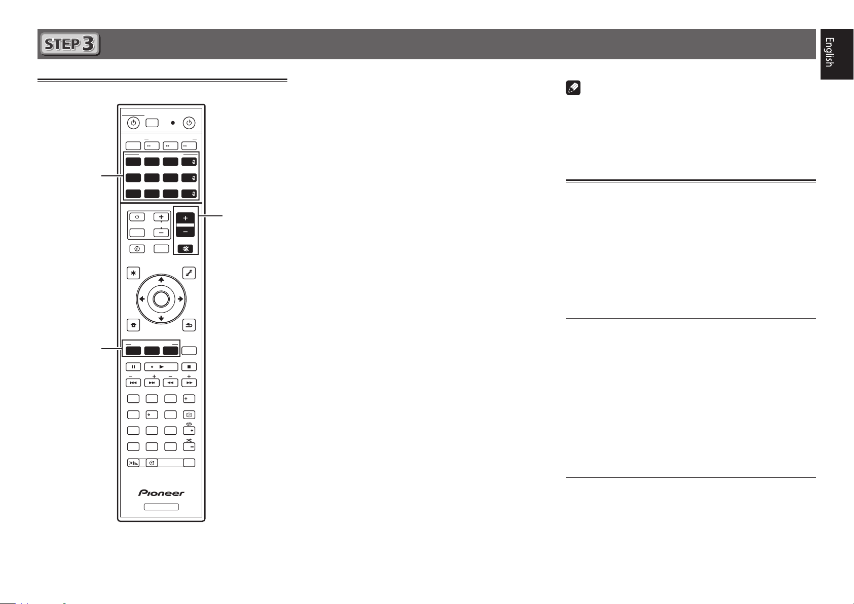
Multichannel playback
STANDBY/ON
ALL ZONE STBY
RECEIVER
MAIN
SOURCE CONTROL
DVDBD
USBADPTROKU
iPod
TUNER
TV
INPUT
STATUS
AUDIO P. VIDEO P.
TOP
MENU
HOME
MENU
SOURCE
SUB ZONE CONTROL
Z2 Z3 HDZ
HDMI
SAT
VOL
OUT P.
ENTER
MHL
CD
NET
ALL
VOLUME
MUTE
TOOLS
RETURN
BT
TV
MENU
1
E.g.) Turn the Blu-ray Disc player connected to the
BD IN
terminal on.
Switch the input of the receiver.
2
E.g.) Press BD to select the BD input.
Press AUTO to select ’AUTO SURROUND’.
3
Also press
SURR
your preferred listening mode.
Start the playback component’s playback.
4
E.g.) Start playback of the Blu-ray Disc player.
Use VOLUME +/– to adjust the volume level.
5
• When a sound can not be heard from center and rear
speakers, press
E.g.) Press the
EXT.STEREO
When there is no sound from the subwoofer
•
Cause – The front speaker is set to LARGE.
ADV
or
SURR
ADV
for multichannel playback. Select
ADV
or
to change listening modes.
button for several times to select
.
HDMI
When a 2-channel audio source is input, the low-frequency
LISTENING MODE
SURRAUTO
MPX
PRESET TUNE
2
13
546
8
79
D.ACCESS
CLR
0
DIMMER SLEEP
CH LV.
ADV
BAND PTY
AUDIO
DISP
CH
CLASS
ENTER
CH
RCU SETUP
Fav
component is not output from the subwoofer but is output
from the front speaker.
Solution – To output from the subwoofer, change the
speaker setting.
Method 1: Change the front speaker setting to
SMALL
.
The low-frequency component is not output from the front
speaker but is output from the subwoofer. When the lowfrequency playback capability of the front speaker is high,
we recommend the setting not be changed.
Method 2: Change the subwoofer setting to
PLUS
.
The low-frequency component is output from the front
speaker and subwoofer. For that reason, low sounds
are sometimes output too much. In such a case, we
recommend not to change or to change to Method 1.
RECEIVER
• For details, see “Speaker Setting” of the operating
instructions.
• When no sound is emitted, increase the volume to
approximately –30 dB.
Note
• When the remote control cannot be used to operate the unit
– When operating the receiver, press
MAIN RECEIVER
before using it.
– When operating functions such as the network, TUNER, or
iPod, press the appropriate function button (
iPod
, etc.) before using.
NET, TUNER
,
Listening to the radio
Press TUNER to select the tuner.
1
If necessary, press
Press TUNE +/– to tune to a station.
2
• Press and hold
will start searching for the next station.
• If you’re listening to an FM station but the reception is
weak, press
to the mono reception mode.
Saving station presets
If you often listen to a particular radio station, it’s convenient to
have the receiver store the frequency for easy recall whenever
you want to listen to that station.
Press TOOLS while receiving a signal from the
1
station you want to store.
The preset number is blinking.
Press PRESET +/– to select the station preset
2
you want, then press ENTER.
The preset number stop blinking and the receiver stores
the station.
Listening to station presets
You will need to have some presets stored to do this.
Press PRESET +/– to select the station preset
you want.
BAND
to change the band (FM or AM).
TUNE +/–
MPX
to select FM MONO and set the receiver
for about a second. The receiver
9
Basic playback (continued)
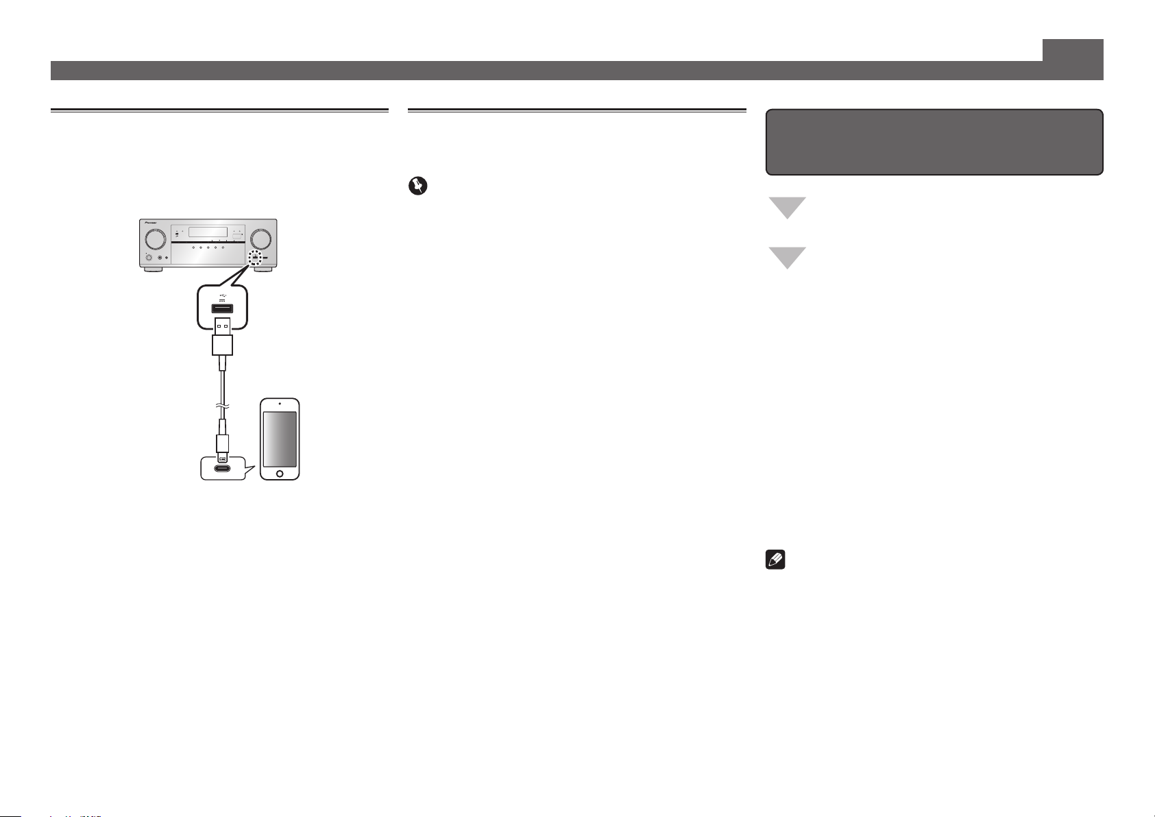
Playing an iPod
• About one minute is required between turning the power
on and completion of startup.
Connect your iPod.
1
An iPod/iPhone can be connected to the receiver.
ADVANCED
FL OFF
MCACC
SPEAKERS CONTROL – MULTI-ZONE – ON / OFFBANDTUNER EDIT TUNE PRESET ENTER
AUTO SURR/ALC/
INPUT
SELECTOR
STANDBY/ON
included with the iPod
Press iPod USB to select the iPod/USB input.
2
STREAM DIRECT
MCACC
PHONES
SETUP MIC
USB cable
When the display shows the names of folders and files,
you’re ready to play music from the iPod.
3
Use
to select a category, then press
/
ENTER to browse that category.
• To return to the previous level any time, press
4
Use
to browse the selected category (e.g.,
/
albums).
• Use
Continue browsing until you arrive at what
5
to move to previous/next levels.
/
you want to play, then press to start
playback.
iPod iPhoneHDMI
iPod iPhone
ADVANCED
STANDARD
STATUS
DIRECT
CONTROL
SURROUND
SURROUND
5 V 1 A
MASTER
VOLUME
5V 1 A
HDMI 5 INPUT
iPod/iPhone
RETURN
Listening to Internet radio stations
• About one minute is required between turning the power
on and completion of startup.
Important
• When using a broadband Internet connection, a contract
with an Internet service provider is required. For more
details, contact your nearest Internet service provider.
• To listen to Internet radio stations, you must have high-
speed broadband Internet access. With a 56 K or ISDN
modem, you may not enjoy the full benefits of Internet
radio.
• Access to content provided by third parties requires a
high speed internet connection and may also require
account registration and a paid subscription. Third
party content services may be changed, suspended,
interrupted, or discontinued at any time without notice,
and Pioneer disclaims any liability in connection with such
occurrences. Pioneer does not represent or warrant that
content services will continue to be provided or available
for a particular period of time, and any such warranty,
express or implied, is disclaimed.
Press NET repeatedly to select the INTERNET
1
RADIO input.
It may take several seconds for this receiver to access the
network.
Use
2
play back, and then press ENTER.
.
to select the Internet radio station to
/
To enjoy the many functions of the
unit to the fullest extent
Launch AVNavigator, and use the “Interactive
Operation Guide”.
Load the CD-ROM into your computer and
download the “Operating Instructions” (PDF)
from the menu screen to read.
Functions
Playing a USB device
#
Bluetooth ADAPTER for Wireless Enjoyment of Music
#
Playback with NETWORK feature
#
Setting the Audio options
#
Setting the Video options
#
Using the MULTI-ZONE controls
#
FAQ
Glossary
Features index
Note
• This unit supports AirPlay. For details, see “Using AirPlay
on iPod touch, iPhone, iPad, and iTunes” of the operating
instructions and the Apple website (http://www.apple.
com).
• This unit’s software can be updated (“Software Update”
of the operating instructions). With Mac OS, it can be
updated using Safari (“Using Safari to update the firmware”
of the operating instructions).
10
© 2014 PIONEER HOME ELECTRONICS CORPORATION.
All rights reserved.