

Page 1
AUDIO/VIDEO MULTI-CHANNEL RECEIVER
RECEPTOR AUDIO-VIDEO MULTICANAL
VSX-920
Register your product on
http://www.pioneerelectronics.com (US)
http://www.pioneerelectronics.ca (Canada)
·
Protect your new investment
The details of your purchase will be on file for reference in the event of an
insurance claim such as loss or theft.
·
Receive free tips, updates and service bulletins on
your new product
·
Improve product development
Your input helps us continue to design products that meet your needs.
·
Receive a free Pioneer newsletter
Registered customers can opt in to receive a monthly newsletter.
Operating Instructions
Manual de instrucciones
Page 2
WARNING
This equipment is not waterproof. To prevent a fire or
shock hazard, do not place any container filled with
liquid near this equipment (such as a vase or flower
pot) or expose it to dripping, splashing, rain or
moisture.
D3-4-2-1-3_A1_En
WARNING
Before plugging in for the first time, read the following
section carefully.
The voltage of the available power supply differs
according to country or region. Be sure that the
power supply voltage of the area where this unit
will be used meets the required voltage (e.g., 230 V
or 120 V) written on the rear panel.
This product is for general household purposes. Any
failure due to use for other than household purposes
(such as long-term use for business purposes in a
restaurant or use in a car or ship) and which requires
repair will be charged for even during the warranty
period.
IMPORTANT NOTICE
THE MODEL NUMBER AND SERIAL NUMBER OF
THIS EQUIPMENT ARE ON THE REAR OR BOTTOM.
RECORD THESE NUMBERS ON YOUR ENCLOSED
WARRANTY CARD AND KEEP IN A SAFE PLACE
FOR FUTURE REFERENCE.
This Class B digital apparatus complies with
Canadian ICES-003.
D3-4-2-1-4*_A1_En
K041_A1_En
D36-AP9-1_A1_En
D8-10-1-3_A1_En
If the AC plug of this unit does not match the AC
outlet you want to use, the plug must be removed
and appropriate one fitted. Replacement and
mounting of an AC plug on the power supply cord of
this unit should be performed only by qualified
service personnel. If connected to an AC outlet, the
cut-off plug can cause severe electrical shock. Make
sure it is properly disposed of after removal.
The equipment should be disconnected by removing
the mains plug from the wall socket when left unused
for a long period of time (for example, when on
vacation).
D3-4-2-2-1a_A1_En
WARNING: Handling the cord on this product or
cords associated with accessories sold with the
product may expose you to chemicals listed on
proposition 65 known to the State of California and
other governmental entities to cause cancer and
birth defect or other reproductive harm.
Wash hands after handling.
D36-P5_B1_En
CAUTION
This product satisfies FCC regulations when shielded
cables and connectors are used to connect the unit
to other equipment. To prevent electromagnetic
interference with electric appliances such as radios
and televisions, use shielded cables and connectors
for connections.
D8-10-3a_A1_En
Information to User
Alterations or modifications carried out without
appropriate authorization may invalidate the user’s
right to operate the equipment.
D8-10-2_A1_En
NOTE:
This equipment has been tested and found to comply with the limits for a Class B digital device, pursuant to Part 15
of the FCC Rules. These limits are designed to provide reasonable protection against harmful interference in a
residential installation. This equipment generates, uses, and can radiate radio frequency energy and, if not installed
and used in accordance with the instructions, may cause harmful interference to radio communications. However,
there is no guarantee that interference will not occur in a particular installation. If this equipment does cause
harmful interference to radio or television reception, which can be determined by turning the equipment off and on,
the user is encouraged to try to correct the interference by one or more of the following measures:
— Reorient or relocate the receiving antenna.
— Increase the separation between the equipment and receiver.
— Connect the equipment into an outlet on a circuit different from that to which the receiver is connected.
— Consult the dealer or an experienced radio/TV technician for help.
D8-10-1-2_A1_En
FEDERAL COMMUNICATIONS COMMISSION DECLARATION OF CONFORMITY
This device complies with part 15 of the FCC Rules. Operation is subject to the following two conditions: (1) This
device may not cause harmful interference, and (2) this device must accept any interference received, including
interference that may cause undesired operation.
Product Name: AUDIO/VIDEO MULTI-CHANNEL RECEIVER
Model Number: VSX-920
Responsible Party Name: PIONEER ELECTRONICS (USA) INC.
SERVICE SUPPORT DIVISION
Address: 1925 E. DOMINGUEZ ST. LONG BEACH, CA 90810-1003, U.S.A.
Phone: 1-800-421-1404
URL: http://www.pioneerelectronics.com
D8-10-4*_C1_En
Page 3
IMPORTANT
The lightning flash with arrowhead symbol,
within an equilateral triangle, is intended to
alert the user to the presence of uninsulated
“dangerous voltage” within the product’s
enclosure that may be of sufficient
magnitude to constitute a risk of electric
shock to persons.
Read these instructions.
1)
Keep these instructions.
2)
Heed all warnings.
3)
Follow all instructions.
4)
Do not use this apparatus near water.
5)
Clean only with dry cloth.
6)
Do not block any ventilation openings. Install in
7)
accordance with the manufacturer’s
instructions.
Do not install near any heat sources such as
8)
radiators, heat registers, stoves, or other
apparatus (including amplifiers) that produce
heat.
Do not defeat the safety purpose of the polarized
9)
or grounding-type plug. A polarized plug has two
blades with one wider than the other
grounding type plug has two blades and a third
grounding prong. The wide blade or the third
prong are provided for your safety. If the provided
plug does not fit into your outlet, consult an
electrician for replacement of the obsolete outlet.
rotect the power cord from being walked on or
10)
P
pinched particularly at plugs, convenience
receptacles, and the point where they exit from
the apparatus.
CAUTION:
TO PREVENT THE RISK OF ELECTRIC
SHOCK, DO NOT REMOVE COVER (OR
BACK). NO USER-SERVICEABLE PARTS
INSIDE. REFER SERVICING TO QUALIFIED
SERVICE PERSONNEL.
CAUTION
RISK OF ELECTRIC SHOCK
DO NOT OPEN
. A
The exclamation point within an equilateral
triangle is intended to alert the user to the
presence of important operating and
maintenance (servicing) instructions in the
literature accompanying the appliance.
11)
use attachments/accessories specified by
Only
the manufacturer.
12)
Use only with the cart, stand, tripod, bracket, or
table specified by the manufacturer, or sold with
the apparatus. When a cart is used, use caution
when moving the cart/apparatus combination to
avoid injury from tip-over.
13)
Unplug this apparatus during lightning storms
or when unused for long periods of time.
14)
Refer all servicing to qualified service personnel.
Servicing is required when the apparatus has
been damaged in any way, such as power-supply
cord or plug is damaged, liquid has been spilled
or objects have fallen into the apparatus, the
apparatus has been exposed to rain or moisture,
does not operate normally
, or has been dropped.
D3-7-13-69_En
D3-4-2-1-1_A1_En
VENTILATION CAUTION
When installing this unit, make sure to leave space
around the unit for ventilation to improve heat radiation
(at least 40 cm at top, 10 cm at rear, and 20 cm at each
side).
WARNING
Slots and openings in the cabinet are provided for
ventilation to ensure reliable operation of the product,
and to protect it from overheating. To prevent fire hazard,
the openings should never be blocked or covered with
items (such as newspapers, table-cloths, curtains) or by
operating the equipment on thick carpet or a bed.
D3-4-2-1-7b*_A1_En
Operating Environment
Operating environment temperature and humidity:
+5 °C to +35 °C (+41 °F to +95 °F); less than 85 %RH
(cooling vents not blocked)
Do not install this unit in a poorly ventilated area, or in
locations exposed to high humidity or direct sunlight (or
strong artificial light)
D3-4-2-1-7c*_A1_En
WARNING
To prevent a fire hazard, do not place any naked flame
sources (such as a lighted candle) on the equipment.
CAUTION
The STANDBY/ON switch on this unit will not
completely shut off all power from the AC outlet.
Since the power cord serves as the main disconnect
device for the unit, you will need to unplug it from the
AC outlet to shut down all power. Therefore, make
sure the unit has been installed so that the power
cord can be easily unplugged from the AC outlet in
case of an accident. To avoid fire hazard, the power
cord should also be unplugged from the AC outlet
when left unused for a long period of time (for
example, when on vacation).
Caution
To prevent fire hazard, the Class 2 Wiring Cable
should be used for connection with speaker, and
should be routed away from hazards to avoid damage
to the insulation of the cable.
D3-4-2-1-7a_A1_En
D3-4-2-2-2a*_A1_En
D3-7-13-67*_A1_En
Page 4

Contents
Thank you for buying this Pioneer product. Please read through these operating instructions so you will know how to operate
your model properly. After you have finished reading the instructions, put them away in a safe place for future reference.
01 Before you start
Checking what’s in the box . . . . . . . . . . . . . . . 7
Loading the batteries . . . . . . . . . . . . . . . . . . . 7
Installing the receiver . . . . . . . . . . . . . . . . . . . 7
Ventilation . . . . . . . . . . . . . . . . . . . . . . . . . . 8
02 Controls and displays
Front panel . . . . . . . . . . . . . . . . . . . . . . . . . . . 9
Operating range of remote control . . . . . . . 10
Display . . . . . . . . . . . . . . . . . . . . . . . . . . . . . 11
Remote control . . . . . . . . . . . . . . . . . . . . . . . 13
03 Connecting your equipment
Determining the speakers’ application . . . . . 16
Other speaker connection . . . . . . . . . . . . . 17
Placing the speakers . . . . . . . . . . . . . . . . . 17
Some tips for improving sound quality . . . . 17
Connecting the speakers . . . . . . . . . . . . . . . 19
Switching the speaker terminal . . . . . . . . . 20
Making cable connections . . . . . . . . . . . . . . 21
HDMI cables . . . . . . . . . . . . . . . . . . . . . . . 21
About HDMI . . . . . . . . . . . . . . . . . . . . . . . . 21
Analog audio cables. . . . . . . . . . . . . . . . . . 22
Digital audio cables . . . . . . . . . . . . . . . . . . 22
Video cables . . . . . . . . . . . . . . . . . . . . . . . . 22
About the video converter . . . . . . . . . . . . . . . 23
Connecting a TV and playback components
Connecting using HDMI. . . . . . . . . . . . . . . 24
Connecting your DVD player with no
HDMI output . . . . . . . . . . . . . . . . . . . . . . . 25
Connecting your TV with no HDMI input. . . 26
Connecting a satellite receiver or other
digital set-top box . . . . . . . . . . . . . . . . . . . . . 27
Connecting an HDD/DVD recorder, VCR
and other video sources . . . . . . . . . . . . . . . . 27
Using the component video jacks . . . . . . . . . 28
Connecting other audio components . . . . . . 28
Connecting antennas . . . . . . . . . . . . . . . . . . 29
Using external antennas. . . . . . . . . . . . . . . 29
Connecting to the front panel video
terminal . . . . . . . . . . . . . . . . . . . . . . . . . . . . 30
Plugging in the receiver . . . . . . . . . . . . . . . . 30
. . . 24
04 Basic Setup
Automatically setting up for surround
sound (MCACC) . . . . . . . . . . . . . . . . . . . . . . 31
Other problems when using the Auto
MCACC Setup. . . . . . . . . . . . . . . . . . . . . . . 33
05 Listening to your system
Basic playback . . . . . . . . . . . . . . . . . . . . . . . 34
Auto playback . . . . . . . . . . . . . . . . . . . . . . . . 35
Listening in surround sound . . . . . . . . . . . . . 35
Using the Advanced surround effects. . . . . 36
Listening in stereo. . . . . . . . . . . . . . . . . . . . . 37
Using Front Stage Surround Advance . . . . . . 37
Using Stream Direct . . . . . . . . . . . . . . . . . . . 38
Using the Sound Retriever. . . . . . . . . . . . . . . 38
Better sound using Phase Control. . . . . . . . . 38
Listening with Acoustic Calibration EQ . . . . . 39
Using surround back channel processing. . . 39
Setting the Up Mix function. . . . . . . . . . . . . . 40
Setting the Audio options . . . . . . . . . . . . . . . 40
Choosing the input signal . . . . . . . . . . . . . . . 43
Using the headphone . . . . . . . . . . . . . . . . . . 43
06 The System Setup menu
Using the System Setup menu . . . . . . . . . . . 44
Manual speaker setup. . . . . . . . . . . . . . . . . . 45
Speaker Setting . . . . . . . . . . . . . . . . . . . . . 45
Crossover Network . . . . . . . . . . . . . . . . . . . 47
Channel Level . . . . . . . . . . . . . . . . . . . . . . . 47
Speaker Distance . . . . . . . . . . . . . . . . . . . . 48
The Input Assign menu . . . . . . . . . . . . . . . . . 48
The Speaker System setting . . . . . . . . . . . . . 49
The Video Parameter setting . . . . . . . . . . . . . 50
Video Converter . . . . . . . . . . . . . . . . . . . . . 50
Resolution . . . . . . . . . . . . . . . . . . . . . . . . . 50
Aspect . . . . . . . . . . . . . . . . . . . . . . . . . . . . 51
07 Using the tuner
Listening to the radio. . . . . . . . . . . . . . . . . . . 52
Improving FM stereo sound . . . . . . . . . . . . 52
Saving station presets . . . . . . . . . . . . . . . . . . 52
Listening to station presets. . . . . . . . . . . . . 53
Naming preset stations. . . . . . . . . . . . . . . . 53
4
En
Page 5

08 Making recordings
Manufactured under license from Dolby
Laboratories. Dolby, Pro Logic, Surround EX
and the double-D symbol are trademarks of
Dolby Laboratories.
Manufactured under license under U.S.
Patent #’s: 5,451,942; 5,956,674; 5,974,380;
5,978,762; 6,226,616; 6,487,535; 7,212,872;
7,333,929; 7,392,195; 7,272,567 & other U.S.
and worldwide patents issued & pending.
DTS and the Symbol are registered
trademarks, & DTS-HD, DTS-HD Master
Audio, and the DTS logos are trademarks of
DTS, Inc. Product includes software. © DTS,
Inc. All Rights Reserved.
Making an audio or a video recording . . . . . . 54
09 Controlling the rest of your system
Setting the remote to control other
components . . . . . . . . . . . . . . . . . . . . . . . . . 55
Selecting preset codes directly . . . . . . . . . . . 55
Clearing all the remote control settings. . . . . 56
Controls for TVs . . . . . . . . . . . . . . . . . . . . . . . 57
Controls for other components . . . . . . . . . . . 58
Preset Code List . . . . . . . . . . . . . . . . . . . . . . 59
10 Other connections
Connecting an iPod. . . . . . . . . . . . . . . . . . . . 62
Connecting your iPod to the receiver . . . . . 62
iPod playback . . . . . . . . . . . . . . . . . . . . . . . 63
Watching photos and video content . . . . . . 64
About iPod . . . . . . . . . . . . . . . . . . . . . . . . . 64
Connecting a USB device . . . . . . . . . . . . . . . 65
Connecting your USB device to the
receiver. . . . . . . . . . . . . . . . . . . . . . . . . . . . 65
Basic playback controls . . . . . . . . . . . . . . . 65
Compressed audio compatibility. . . . . . . . . 66
Bluetooth® ADAPTER for Wireless
Enjoyment of Music. . . . . . . . . . . . . . . . . . . . 67
Wireless music play . . . . . . . . . . . . . . . . . . 67
Connecting Optional Bluetooth
ADAPTER . . . . . . . . . . . . . . . . . . . . . . . . . . 67
Pairing Bluetooth ADAPTER and
Bluetooth wireless technology device . . . . . 68
Listening to Music Contents of
Bluetooth wireless technology device
with Your System . . . . . . . . . . . . . . . . . . . . 68
Listening to Satellite Radio . . . . . . . . . . . . . . 69
Connecting your SiriusConnectTM Tuner
Listening to SIRIUS Radio. . . . . . . . . . . . . . 70
Saving channel presets. . . . . . . . . . . . . . . . 71
Using the SIRIUS Menu . . . . . . . . . . . . . . . 71
. . . 70
English
English Italiano Français
Deutsch
Français
Italiano
Nederlands
Español
Nederlands
11 Additional information
Troubleshooting . . . . . . . . . . . . . . . . . . . . . . 72
HDMI . . . . . . . . . . . . . . . . . . . . . . . . . . . . . 75
Important information regarding the
HDMI connection . . . . . . . . . . . . . . . . . . . . 76
iPod messages . . . . . . . . . . . . . . . . . . . . . . 76
USB messages . . . . . . . . . . . . . . . . . . . . . . 77
SIRIUS radio messages . . . . . . . . . . . . . . . 77
Resetting the main unit. . . . . . . . . . . . . . . . . 78
Specifications . . . . . . . . . . . . . . . . . . . . . . . . 78
Cleaning the unit. . . . . . . . . . . . . . . . . . . . . . 79
EspañolDeutsch
5
En
Page 6
Flow of settings on the receiver
Front
Left (L)
*Front Height
Left (FHL)
*Front Height
Right (FHR)
Surround
Left (SL)
*Surround Back
Left (SBL)
*Surround Back
Right (SBR)
Surround
Right (SR)
Center (C)
Subwoofer (SW)
Listening
position
Front
Right (R)
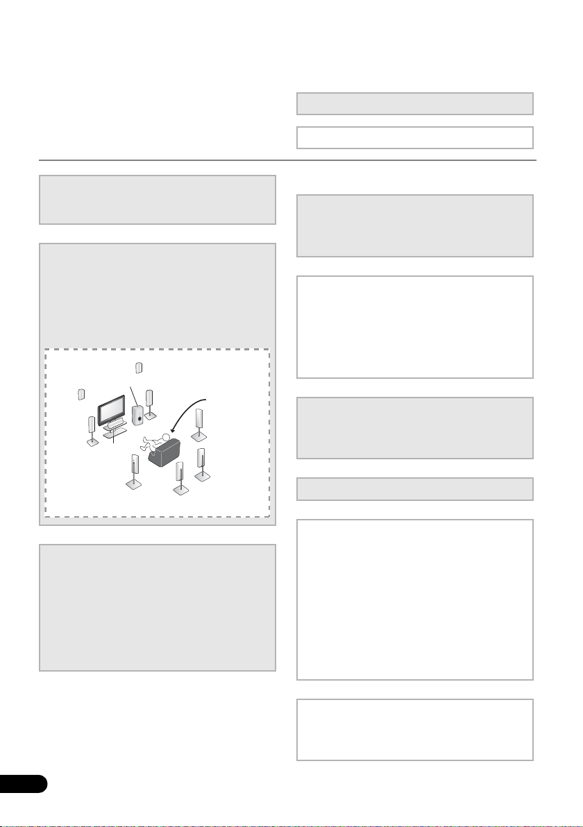
The unit is a full-fledged AV receiver equipped
with an abundance of functions and terminals.
It can be used easily after following the
procedure below to make the connections and
settings.
The colors of the steps indicate the following:
Required setting item
Setting to be made as necessary
1
Before you start
• Checking what’s in the box (page 7)
• Loading the batteries (page 7)
2
Connecting the speakers
Where you place the speakers will have a big
effect on the sound. Place your speakers as
shown below for the best surround sound effect.
• Determining the speakers’ application
(page 16)
• Connecting the speakers (page 19)
3
Connecting the components
For surround sound, you’ll want to hook up
using a digital connection from the BD/DVD
player to the receiver.
• About the video converter (page 23)
• Connecting a TV and playback components
(page 24)
• Connecting antennas (page 29)
6
En
• Plugging in the receiver (page 30)
4
Power On
Make sure you’ve set the video input on your TV to
this receiver. Check the manual that came with
the TV if you don’t know how to do this.
5
The Speaker System setting (page 49)
(Specify either using the surround back or
front height speaker.)
The Input Assign menu (page 48)
(When using connections other than the
recommended connections.)
6
Use the on-screen automatic MCACC
setup to set up your system
• Automatically setting up for surround sound
(MCACC) (page 31)
7
Basic playback (page 34)
8
Adjusting the sound as desired
•Using the various listening modes
• Using the Sound Retriever (page 38)
• Better sound using Phase Control (page 38)
• Listening with Acoustic Calibration EQ
(page 39)
• Using surround back channel processing
(page 39)
• Setting the Up Mix function (page 40)
• Setting the Audio options (page 40)
• Choosing the input signal (page 43)
• Manual speaker setup (page 45)
9
Making maximum use of the remote
control
• Setting the remote to control other
components (page 55)
Page 7
Before you start 01
English
Français
Deutsch
Nederlands
Italiano
Español
English
Français
Deutsch
Nederlands
Italiano
Español
These symbols are only valid
in the European Union.
K058c_A1_En
(Symbol examples for batteries)
Pb
Chapter 1:
Before you start
• Batteries with the same shape may have
Checking what’s in the box
Please check that you’ve received the following
supplied accessories:
• Setup microphone
• Remote control
• Dry cell batteries (AAA size IEC R03) x2
• AM loop antenna
•FM wire antenna
• iPod cable
• These operating instructions
Loading the batteries
different voltages. Do not use different
batteries together.
• When disposing of used batteries, please
comply with governmental regulations or
environmental public instruction’s rules
that apply in your country or area.
• Do not use or store batteries in direct
sunlight or other excessively hot place,
such as inside a car or near a heater. This
can cause batteries to leak, overheat,
explode or catch fire. It can also reduce
the life or performance of batteries.
The batteries included with the unit are to
check initial operations; they may not last over
a long period. We recommend using alkaline
batteries that have a longer life.
CAUTION
Incorrect use of batteries may result in such
hazards as leakage and bursting. Observe the
following precautions:
• Never use new and old batteries together.
• Insert the plus and minus sides of the
batteries properly according to the marks
in the battery case.
Installing the receiver
• When installing this unit, make sure to put
it on a level and stable surface.
Don’t install it on the following places:
– on a color TV (the screen may distort)
– near a cassette deck (or close to a device that
gives off a magnetic field). This may interfere
with the sound.
– in direct sunlight
– in damp or wet areas
– in extremely hot or cold areas
– in places where there is vibration or other
movement
– in places that are very dusty
– in places that have hot fumes or oils (such as
a kitchen)
7
En
Page 8
Before you start01
Receiver
40 cm (16 inches)
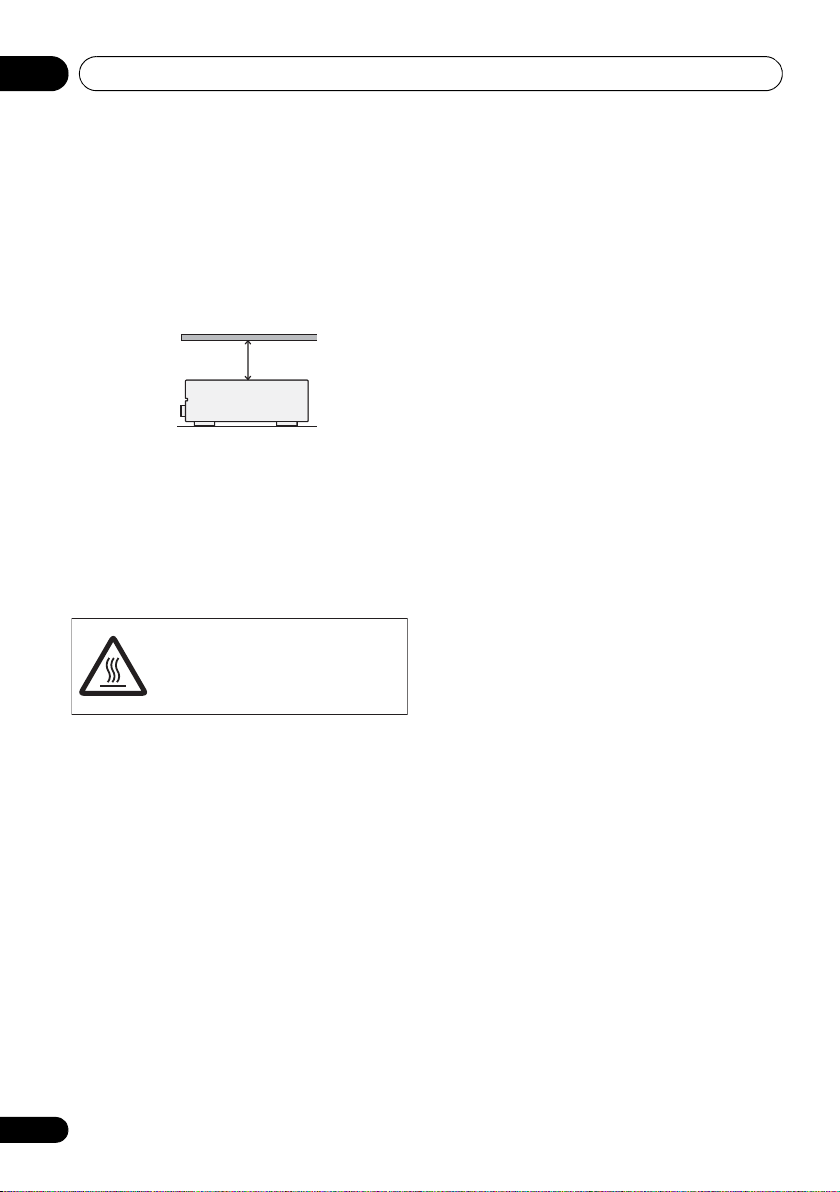
CAUTION:
HOT SURFACE. DO NOT TOUCH.
The top surface over the internal
heatsink may become hot when
operating this product continuously.
Ventilation
When installing this unit, make sure to leave
space around the unit for ventilation to improve
heat dispersal (at least 40 cm (16 in.) at the
top). If not enough space is provided between
the unit and walls or other equipment, heat will
build up inside, interfering with performance
and/or causing malfunctions.
Slot and openings in the cabinet are provided
for ventilation and to protect the equipment
from overheating. To prevent fire hazard, do not
place anything directly on top of the unit, make
sure the openings are never blocked or covered
with items (such as newspapers, table-cloths
and curtains), and do not operate the
equipment on thick carpet or a bed.
8
En
Page 9
Controls and displays 02
English
Français
Deutsch
Nederlands
Italiano
Español
SPEAKERS
AUTO/DIRECT STEREO/ ALC STANDARD
LISTENING MODE
ADV SURROUND DIRECT CONTROL
iPod iPhone
DIMMER DISPLAY BAND TUNE TUNER EDIT PRESET ENTER
PHONES
INPUT
SELECTOR
STANDBY/ON
PHASE
CONTROL
MASTER
VOLUME
MCACC
SETUP MIC
AUDIO/VIDEO MULTI- CHANNEL RECEIVER
VSX
-920
VIDEO INPUT
AUDIOLRVIDEO
iPod
iPhone
USB
1 27854 63
9
1110 141312
Note
Chapter 2:
Controls and displays
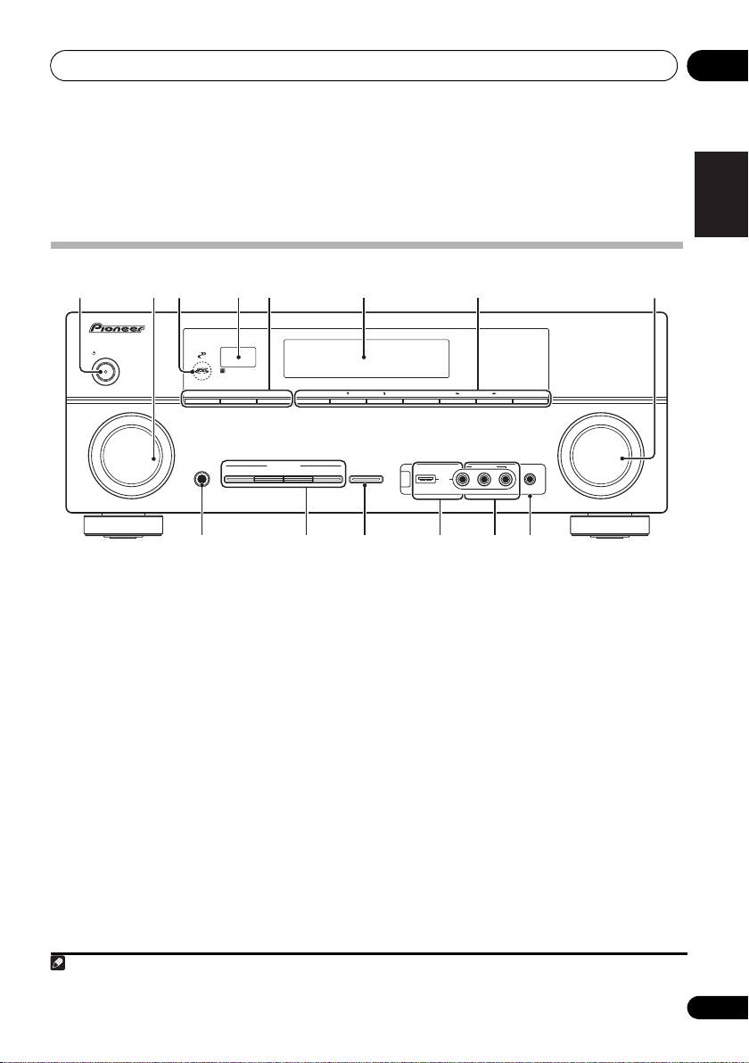
Front panel
1
STANDBY/ON
2
INPUT SELECTOR
dial
Selects an input source.
3
MCACC
indicator
Lights when Acoustic Calibration EQ (page 39)
is on (Acoustic Calibration EQ is automatically
set to on after the Auto MCACC Setup
(page 31)).
4 Remote sensor
Receives the signals from the remote control
(see Operating range of remote control on
page 10).
5
SPEAKERS
See Switching the speaker terminal on
page 20.
DIMMER
Dims or brightens the display. The
brightness can be controlled in four steps.
DISPLAY
Switches the display of this unit. The
listening mode, sound volume, Speaker
System setting or input name can be
checked by selecting an input source.
6 Character display
See Display on page 11.
7 Tuner control buttons
BAND
Switches between AM, FM ST (stereo) and
FM MONO radio bands (page 52).
TUNE /
Used to find radio frequencies (page 52)
and SIRIUS Radio channels (page 70).
TUNER EDIT
Use with TUNE /, PRESET / and
ENTER to memorize and name stations for
recall (page 52, 53). Used to preset the
channel in SIRIUS Radio (page 70).
1 The Speaker System setting may or may not be displayed, depending on the input source you have selected.
1
9
En
Page 10
Controls and displays02
30°
7 m (23 ft.)
30°
PRESET /
Use to select preset radio stations
(page 53) and to select SIRIUS Radio
channels (page 70).
8
MASTER VOLUME
PHONES
9
Use to connect headphones. When the
headphones are connected, there is no sound
output from the speakers (page 43).
10 Listening mode buttons
AUTO/DIRECT
Switches between Auto surround mode
(Auto playback on page 35) and Stream
Direct playback. Stream Direct playback
bypasses the tone controls for the most
accurate reproduction of a source
(page 38).
STEREO/ALC
Switches between stereo playback, Auto
level control stereo mode (page 37) and
Front Stage Surround Advance modes
(page 37).
STANDARD
Press for Standard decoding and to switch
between the various 2 Pro Logic II, 2 Pro
Logic IIx, 2 Pro Logic IIz and NEO:6
options (page 34).
ADV SURROUND
Switches between the various surround
modes (page 36).
11
iPod iPhone DIRECT CONTROL
Change the receiver’s input to the iPod and
enable iPod operations on the iPod (page 64).
12
iPod iPhone/USB
Use to connect your Apple iPod or USB mass
storage device as an audio source (page 62
and page 65).
13
AUDIO/VIDEO
See Connecting to the front panel video terminal
on page 30.
jack
dial
terminal
input
14
MCACC SETUP MIC
Use to connect a microphone when
performing Auto MCACC setup.
jack
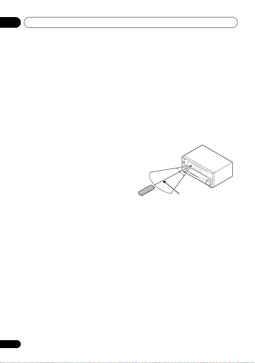
Operating range of remote control
The remote control may not work properly if:
• There are obstacles between the remote
control and the receiver’s remote sensor.
• Direct sunlight or fluorescent light is
shining onto the remote sensor.
• The receiver is located near a device that is
emitting infrared rays.
• The receiver is operated simultaneously
with another infrared remote control unit.
10
En
Page 11
Controls and displays 02
English
Français
Deutsch
Nederlands
Italiano
Español
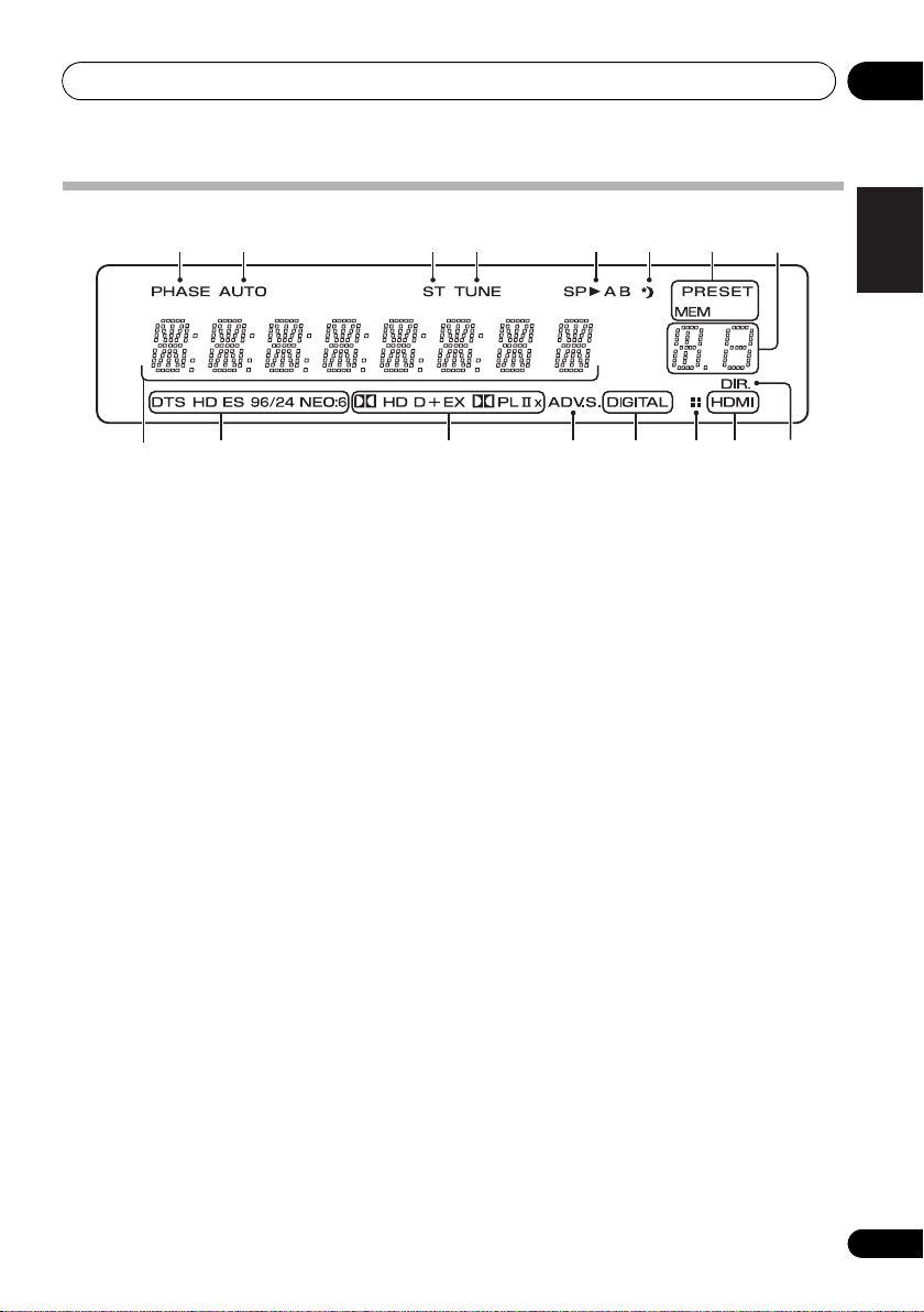
Display
1 2 3 4 5 6 7
8
9
1PHASE
Lights when the Phase Control is switched on
(page 38).
2AUTO
Lights when the Auto Surround feature is
switched on (see Auto playback on page 35).
3ST
Lights when a stereo FM broadcast is being
received in auto stereo mode.
4TUNE
Lights when a normal broadcast channel or
SIRIUS channel is being received.
5 Speaker indicators
Indicates the speaker terminal, A and/or B, to
which audio signal output is currently set
(page 20).
6 Sleep timer indicator
Lights when the receiver is in sleep mode
(page 13).
7 Tuner/SIRIUS preset indicators
PRESET
Shows when a preset radio station is
registered or called.
MEM
Blinks when a radio station is registered.
8 PRESET information or input signal
indicator
Shows the preset number of the tuner or the
input signal type, etc.
10 11 12 13 13 1514
9 Character display
Displays various system information.
10 DTS indicators
DTS
Lights when a source with DTS encoded
audio signals is detected.
HD
Lights when a source with DTS-EXPRESS
or DTS-HD encoded audio signals is
detected.
ES
Lights to indicate DTS-ES decoding.
96/24
Lights when a source with DTS 96/24
encoded audio signals is detected.
NEO:6
When one of the NEO:6 modes of the
receiver is on, this lights to indicate NEO:6
processing (page 35).
11 Dolby Digital indicators
2D
Lights when a Dolby Digital encoded signal
is detected.
2D
+
Lights when a source with Dolby Digital
Plus encoded audio signals is detected.
11
En
Page 12

Controls and displays02
2HD
Lights when a source with Dolby TrueHD
encoded audio signals is detected.
EX
Lights to indicate Dolby Digital EX
decoding.
2PLll(x)
Lights to indicate 2 Pro Logic II / 2 Pro
Logic IIx decoding. Light will go off during
2 Pro Logic IIz decoding. (see Listening in
surround sound on page 35 for more on
this).
12 ADV.S.
Lights when one of the Advanced Surround
modes has been selected (see Using the
Advanced surround effects on page 36 for more
on this).
13 SIGNAL SELECT indicators
DIGITAL
Lights when a digital audio signal is
selected.
Blinks when a digital audio signal is
selected and selected audio input is not
provided.
HDMI
Lights when an HDMI signal is selected.
Blinks when an HDMI signal is selected
and selected HDMI input is not provided.
14 Up Mix/DIMMER indicator
Lights when the Up Mix function is set to ON
(see page 39). Also, lights when DIMMER is set
to off.
15 DIR.
Lights when the DIRECT or PURE DIRECT
mode is switched on (page 38).
12
En
Page 13
Controls and displays 02
English
Français
Deutsch
Nederlands
Italiano
Español
RECEIVER
2
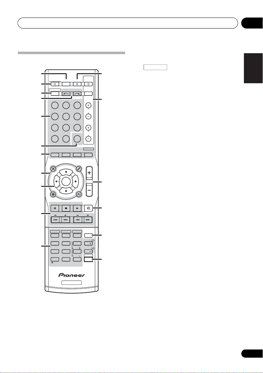
Remote control
1
RECEIVER
2
RECEIVER
3
4
INPUT SELECT
BD DVD
DVR CD
5
ADAPTER iP od USB
TUNER
SIRIUS
6
7
8
9
10
11
AUTO/
DIRECT
AUDIO
PARAMETER
TOP
MENU
T
E
S
E
R
P
HOME
MENU
SETUP
iPod CTRL
CATEGORY
HDD
1
S.RETRIEVER
4
MIDNIGHT
7
DIMMER
CLR
+
/
D.ACCESS
BASS
10
STEREO/
A.L.C.
N
U
E
T
ENTER
T
E
U
N
DVD
2
SB CH
5
SPEAKERS
8
0
RECEIVER
1
SLEEP
Press to change the amount of time before the
receiver switches into standby (30 min – 60
min – 90 min – Off). You can check the
remaining sleep time at any time by pressing
SLEEP once.
SOURCESLEEP
TV
CD-R
VIDEO
SIGNAL SEL
STANDARD
TUNER EDIT
TOOLS
P
R
E
S
E
T
RETURN
DTV/ TV
TRE
VCR
3
CH SELECT
6
LEV
9
LEV
ENTER
CONTROL
INPUT
BD MENU
ADV SURR
MASTER
VOLUME
MENU
BAND
MUTE
MEMORY
CH
PHASE
CH
SHIFT
DISP
TV
CH
VOL
EQ
12
13
14
15
16
17
RECEIVER
Switches the receiver between standby and on.
3
Switches the remote to control the receiver
(used to select the white commands above the
number buttons (S.RETRIEVER, etc)). Also use
this button to set up surround sound (page 44)
or Audio parameters (page 40).
4
INPUT SELECT
Use to select the input source.
5
MULTI CONTROL
Press to select control of other components
(see
Controlling the rest of your system on
page 55
).
6 SIGNAL SEL
Use to select an input signal (page 43).
7 Listening mode buttons
AUTO/DIRECT
Switches between Auto surround mode
(Auto playback on page 35) and Stream
Direct playback. Stream Direct playback
bypasses the tone controls for the most
accurate reproduction of a source
(page 38).
STEREO/A.L.C.
Switches between stereo playback, Auto
level control stereo mode (page 37) and
Front Stage Surround Advance modes
(page 37).
STANDARD
Press for Standard decoding and to switch
between 2 Pro Logic II options (page 35).
ADV SURR
Switches between the various surround
modes (page 36).
Press BD first to access:
BD MENU*
Displays the disc menu of Blu-ray Discs.
buttons
13
En
Page 14

Controls and displays02
RECEIVER
Note
RECEIVER
8 System Setup and component control
buttons
The following button controls can be accessed
after you have selected the corresponding
MULTI CONTROL button (BD, DVD, etc.).
Press first to access:
AUDIO PARAMETER
Use to access the Audio options (page 40).
SETUP
Press to access the System Setup menu
(page 44).
RETURN
Confirm and exit the current menu screen.
Press BD, DVD or DVR first to access:
TOP MENU
Displays the disc ‘top’ menu of a BD/DVD.
HOME MENU
Displays the HOME MENU screen.
RETURN
Confirm and exit the current menu screen.
MENU
Displays the TOOLS menu of Blu-ray Disc
player.
Press TUNER or SIRIUS first to access:
TUNER EDIT
Memorizes stations for recall (page 52 and
71). When TUNER is pressed, also used to
change the name (page 53).
BAND
Switches between AM, FM ST (stereo) and
FM MONO radio bands (page 52).
CATEGORY
Press to browse SIRIUS radio broadcasts.
Press iPod USB first to access:
iPod CTRL
Switches between the iPod controls and
the receiver controls (page 64).
9
(TUNE /, PRESET /
),
ENTER
Use the arrow buttons when setting up your
surround sound system (page 44). Also used to
control BD/DVD menus/options.
Use the TUNE / buttons can be used to
find radio frequencies (page 52) and the
PRESET / buttons can be used to select
preset radio stations (page 53).
10 Component control buttons
The main buttons (, , etc.) are used to
control a component after you have selected it
using the input source buttons.
The controls above these buttons can be
accessed after you have selected the
corresponding input source button (BD, DVD,
DVR and CD). These buttons also function as
described below.
RECEIVER
Press first to access:
BASS –/+
Use to adjust Bass
TRE –/+
Use to adjust Treble
1
1
Press TV first to access:
DTV/TV
Switches between the DTV and analog TV
input modes for Pioneer flat panel TVs.
11 Number buttons and other component
controls
Use the number buttons to directly select a
radio frequency (page 52) or the tracks on a
CD, etc. There are other buttons that can be
accessed after the button is
pressed. (For example MIDNIGHT, etc.)
HDD*, DVD*, VCR*
These buttons switch between the hard
disk, DVD and VCR controls for HDD/DVD/
VCR recorders.
14
En
1 The tone controls are disabled when the listening mode is set to DIRECT or PURE DIRECT.
Page 15

Controls and displays 02
English
Français
Deutsch
Nederlands
Italiano
Español
Note
S.RETRIEVER
Press to restore CD quality sound to
compressed audio sources (page 38).
SB CH
Press to select ON, AUTO, OFF the
surround back channel.
CH SELECT
Press repeatedly to select a channel, then
use LEV +/– to adjust the level (page 47).
LEV +/–
Use to adjust the channel level.
EQ
Press to switch on/off Acoustic Calibration
EQ setting (page 39).
MIDNIGHT
Switches to Midnight or Loudness
listening (page 41).
SPEAKERS
See Switching the speaker terminal on
page 20.
PHASE
Press to switch on/off Phase Control
(page 38).
DIMMER
Dims or brightens the display. The
brightness can be controlled in four steps.
Press SIRIUS first to access:
D.ACCESS
After pressing, you can access a radio
station directly using the number buttons
(page 70).
12
SOURCE
Press to turn on/off other components
connected to the receiver (see page 58 for
more on this).
13
TV CONTROL
These buttons are dedicated to control the TV
assigned to the TV button. Thus if you only
have one TV to hook up to this system assign it
to the TV button (see page 57 for more on
this).
Use to turn on/off the power of the TV.
INPUT
Use to select the TV input signal.
CH +/–
Use to select channels.
VOL +/–
Use to adjust the volume on your TV.
14
MASTER VOLUME
Use to set the listening volume.
15
MUTE
Mutes/unmutes the sound.
16
DISP
Switches the display of this unit. The listening
mode, sound volume, Speaker System setting
or input name can be checked by selecting an
input source.
17
SHIFT
Press to access the ‘boxed’ commands (above
the buttons) on the remote. These buttons are
marked with an asterisk (* ) in this section.
buttons
+/–
1
1 The Speaker System setting may or may not be displayed, depending on the input source you have selected.
15
En
Page 16
Connecting your equipment03
SL
L
SW
C
R
SR
SBL
SBR
L
R
Speaker B
Front height
Surround back
Chapter 3:
Connecting your equipment
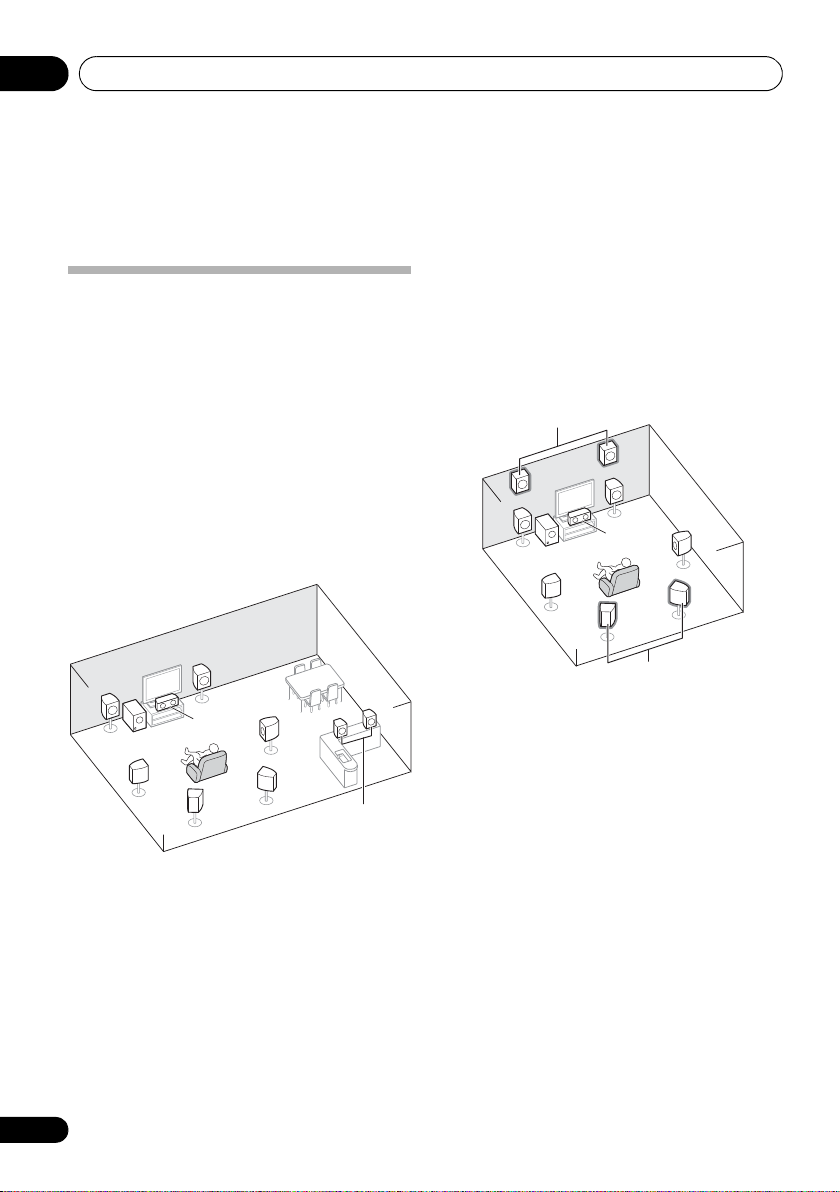
• It is also possible to only connect one of the
Determining the speakers’
application
This unit permits you to build various surround
systems, in accordance with the number of
speakers you have.
• Be sure to connect speakers to the front
left and right channels (L and R).
Choose one from Plans [A] or [B] below.
[A] 7.1 channel surround (Surround back)
system & Speaker B connection
*Default setting
• Speaker System setting: Surr.Back
surround back speaker (SB) or neither.
[B] 7.1 channel surround system (Front
height or Surround back)
• Speaker System setting: Height or
Surr.Back
FHR
FHL
L
SW
R
C
SR
A 7.1 ch surround (Surround back) system
connects the left and right front speakers (L/R),
the center speaker (C), the left and right
surround speakers (SL/SR), the left and right
surround back speakers (SBL/SBR), and the
subwoofer (SW).
With these connections you can
simultaneously enjoy 5.1-channel surround
sound in the main zone with stereo playback of
the same sound on the B speakers. (
is output from the surround back speaker.
16
En
No sound
)
SL
SBL
SBR
A 7.1 ch surround (Front height) system
connects the left and right front speakers (L/R),
the center speaker (C), the left and right front
height speakers (FHL/FHR), the left and right
surround speakers (SL/SR), and the subwoofer
(SW). This surround system produces a more
true-to-life sound from above.
A 7.1 ch surround (Surround back) system
connects the left and right front speakers (L/R),
the center speaker (C), the left and right
surround speakers (SL/SR), the left and right
surround back speakers (SBL/SBR), and the
subwoofer (SW).
• Sound will be output from either the front
height speaker or the surround back
speaker depending on which one was
selected in the Speaker System setting.
(see The Speaker System setting on
page 49).
Page 17
Connecting your equipment 03
English
Français
Deutsch
Nederlands
Italiano
Español
L
SW
C
FHL
SL
SBL
SBR
SB
SR
R
FHR
30 30
60
120 120
Other speaker connection
• Your favorite speaker connections can be
selected even if you have fewer than 5.1
speakers.
• When not connecting a subwoofer,
connect speakers with low frequency
reproduction capabilities to the front
channel. (The subwoofer’s low frequency
component is played from the front
speakers, so the speakers could be
damaged.)
• After connecting, be sure to conduct
the Auto MCACC (speaker environment
setting) procedure.
See Automatically setting up for surround
sound (MCACC) on page 31.
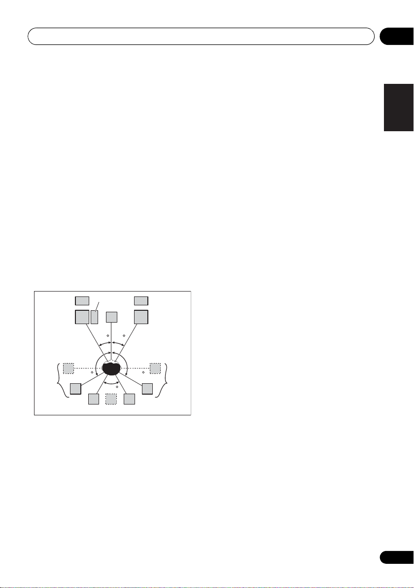
Placing the speakers
Refer to the chart below for placement of
speakers you intend to connect.
• Place the surround speakers at 120º from
the center. If you, (1) use the surround back
speaker, and, (2) don’t use the front height
speakers, we recommend placing the
surround speaker right beside you.
• If you intend to connect only one surround
back speakers, place it directly behind you.
• Place the left and right front height
speakers at least one meter directly above
the left and right front speakers.
Some tips for improving sound quality
Where you put your speakers in the room has
a big effect on the quality of the sound. The
following guidelines should help you to get the
best sound from your system.
• The subwoofer can be placed on the floor.
Ideally, the other speakers should be at
about ear-level when you’re listening to
them. Putting the speakers on the floor
(except the subwoofer), or mounting them
very high on a wall is not recommended.
• For the best stereo effect, place the front
speakers 2 m to 3 m (6 ft. to 9 ft.) apart, at
equal distance from the TV.
• If you’re going to place speakers around
your CRT TV, use shielded speakers or
place the speakers at a sufficient distance
from your CRT TV.
• If you’re using a center speaker, place the
front speakers at a wider angle. If not,
place them at a narrower angle.
• Place the center speaker above or below
the TV so that the sound of the center
channel is localized at the TV screen. Also,
make sure the center speaker does not
cross the line formed by the leading edge
of the front left and right speakers.
• It is best to angle the speakers towards the
listening position. The angle depends on
the size of the room. Use less of an angle
for bigger rooms.
• Surround and surround back speakers
should be positioned 60 cm to 90 cm (2 ft.
to 3 ft.) higher than your ears and titled
slight downward. Make sure the speakers
don’t face each other. For DVD-Audio, the
speakers should be more directly behind
the listener than for home theater
playback.
• If the surround speakers cannot be set
directly to the side of the listening position
with a 7.1-channel system, the surround
effect can be enhanced by turning off the
Up Mix function (see Setting the Up Mix
function on page 40).
17
En
Page 18

Connecting your equipment03
• Try not to place the surround speakers
farther away from the listening position
than the front and center speakers. Doing
so can weaken the surround sound effect.
CAUTION
• Make sure that all speakers are securely
installed. This not only improves sound
quality, but also reduces the risk of
damage or injury resulting from speakers
being knocked over or falling in the event of
external shocks such as earthquakes.
Important
• The Speaker System setting must be set if
the above connections are performed.
Select Surr.Back if the surround back
speaker or speaker B is connected, and
Height if the front height speaker is
connected (see The Speaker System setting
on page 49).
18
En
Page 19
Connecting your equipment 03
English
Français
Deutsch
Nederlands
Italiano
Español
IN BD
R
L
IN
R
L
OUT
R
L
IN
IN
IN
CD
TV/SAT
DVD BD
MONITOR OUT
PRPBY
RL
Class 2 Wiring
DVD IN BD IN
OUT
MONITOR
COMPONENT VIDEO
ANTENNA
TV/SAT
IN
DVR/VCR
OUT IN
FRONT CENTER
RL
SURROUND SURROUND BACK
RLRL(Single
)
CD-R/TAPE
CD-R/TAPE
DVR/VCR
DVR/VCR
DVD
TV/SAT
COAXIAL
OPTICAL
(CD)
IN
ASSIGNABLE
ASSIGNABLE
OUT
HDMI
DVR/VCR
1
(
CD-R/TAPE
)
IN
AUDIO
SIRIUS
IN
FM
UNBAL
75
AM
LOOP
ADAPTER PORT
VIDEO
(
OUTPUT 5 V 100 mA MAX
)
1
(BD)
IN
1
(
DVD
)
IN
2
1 2
ASSIGNABLE
SPEAKERS
FRONT HEIGHT /
1
B
SPEAKERS
A
2
IN
2
SUBWOOFER
PRE OUT
LINE LEVEL
INPUT
Powered subwoofer
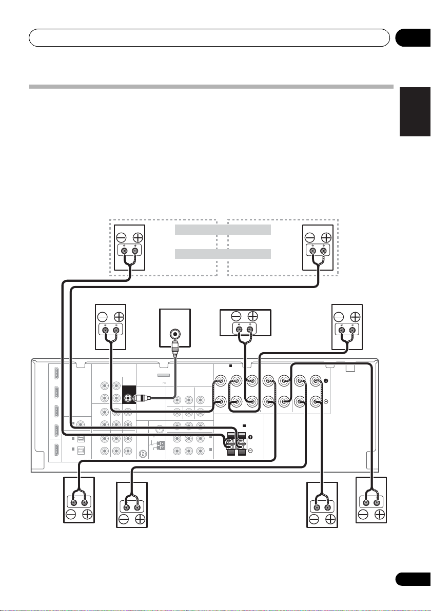
The front height
terminals can also be
used for Speaker B.
Speaker B - left
Speaker B - right
Speaker B setting
Front height left
Front height setting
Front height right
Front left
Center
Surround right
Surround back left
Surround back right
Front right
Surround left
When using only one surround back speaker,
connect it to the SURROUND BACK L
(Single) terminals.
Connecting the speakers
The receiver will work with just two stereo
speakers (the front speakers in the diagram)
but using at least three speakers is
recommended, and a complete setup is best
for surround sound.
Make sure you connect the speaker on the
right to the right (R) terminal and the speaker
on the left to the left (L) terminal. Also make
sure the positive and negative (+/–) terminals
on the receiver match those on the speakers.
You can use the speakers connected to the
front height (B speaker) terminals to listen to
stereo playback in another room. See
Switching the speaker terminal on page 20 for
the listening options with this setup.
You can use speakers with a normal
impedance between 6 Ω and 16 Ω.
Be sure to complete all connections before connecting this unit to the AC power source.
19
En
Page 20
Connecting your equipment03
123
10 mm
(
3
/8 in.)
12 3
10 mm
(
3
/8 in.)
Note
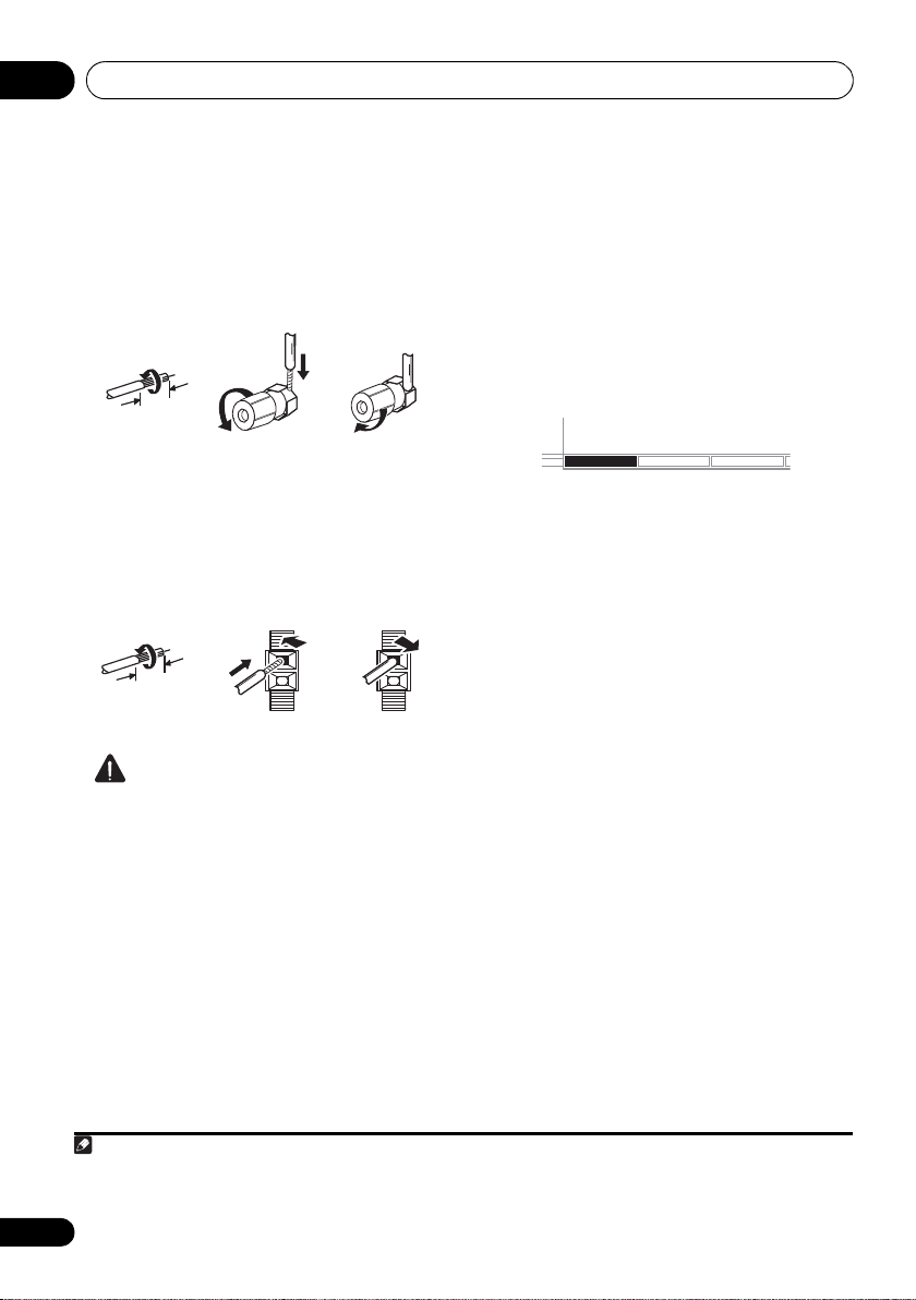
Bare wire connections
A-Speaker terminals:
1 Twist exposed wire strands together.
2 Loosen terminal and insert exposed wire.
3 Tighten terminal.
B-Speaker terminals:
1 Twist exposed wire strands together.
2 Push open the tabs and insert exposed
wire.
3 Release the tabs.
CAUTION
• These speaker terminals carry
HAZARDOUS LIVE voltage. To prevent
the risk of electric shock when connecting
or disconnecting the speaker cables,
disconnect the power cord before touching
any uninsulated parts.
• Make sure that all the bare speaker wire is
twisted together and inserted fully into the
speaker terminal. If any of the bare speaker
wire touches the back panel it may cause
the power to cut off as a safety measure.
Switching the speaker terminal
If you selected Surr.Back in The Speaker
System setting on page 49, you can switch
between speakers using the SPEAKERS
button. If you selected Height, the button will
si mp ly sw it ch yo ur ma in sp ea ke r t er mi na l o n o r
off. The options below are for the Surr.Back
setting only.
• Use the SPEAKERS button on the front
panel to select a speaker terminal setting.
Press repeatedly to choose a speaker terminal
option:
• SPA – Sound is output from the speakers
connected to the A-speaker terminals
(multichannel playback is possible).
• SPB – Sound is output from the two
speakers connected to the B-speaker
terminals (only stereo playback is
possible).
• SPAB – Sound is output from the Aspeaker terminals, the two speakers in the
B-speaker terminals, and the subwoofer.
Multichannel sources are downmixed only
when the STEREO or ALC mode is se lected
for stereo output from A- and B-speaker
terminals.
• SP – No sound is output from the
speakers.
1
2
SPEAKERS DIMMER DISPLAY
1 All speaker terminals (except Speaker B connections) are switched off when headphones are connected.
2 The subwoofer output depends on the settings you made in Speaker Setting on page 45. However, if SPB is selected above,
no sound is heard from the subwoofer (the LFE channel is not downmixed).
20
En
Page 21
Connecting your equipment 03
English
Français
Deutsch
Nederlands
Italiano
Español
Note
Be careful to connect the terminal in the
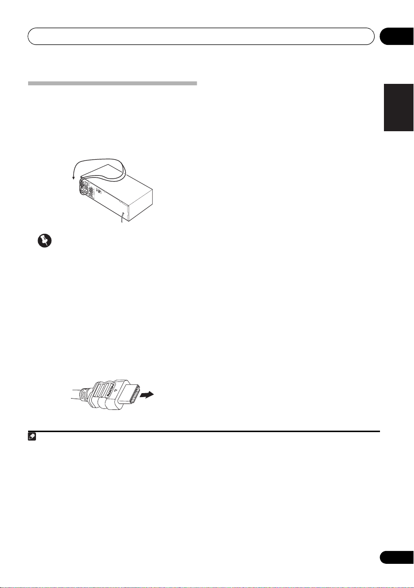
Making cable connections
Make sure not to bend the cables over the top
of this unit (as shown in the illustration). If this
happens, the magnetic field produced by the
transformers in this unit may cause a
humming noise from the speakers.
Important
• Before making or changing connections,
switch off the power and disconnect the
power cord from the AC outlet.
• Before unplugging the power cord, switch
the power into standby.
HDMI cables
Both video and sound signals can be
transmitted simultaneously with one cable. If
connecting the player and the TV via this
receiver, for both connections, we recommend
using HDMI cables.
1
proper direction.
About HDMI
The HDMI connection transfers
uncompressed digital video, as well as almost
every kind of digital audio that the connected
component is compatible with, including
DVD-Video, DVD-Audio, SACD, Dolby Digital
Plus, Dolby TrueHD, DTS-HD Master Audio
(see below for limitations), Video CD/Super
VCD and CD.
This receiver incorporates High-Definition
Multimedia Interface (HDMI
This receiver supports the functions described
below through HDMI connections.
• Digital transfer of uncompressed video
(contents protected by HDCP (1080p/24,
1080p/60, etc.))
• 3D signal transfer
• Deep Color signal transfer
• x.v.Color signal transfer
• Input of multi-channel linear PCM digital
audio signals (192 kHz or less) for up to 8
channels
•
Input of the following digital audio formats:
– Dolby Digital, Dolby Digital Plus, DTS,
High bitrate audio (Dolby TrueHD, DTS-HD
Master Audio), DVD-Audio, CD, SACD
(DSD signal), Video CD, Super VCD
3
®
) technology.
3
3
2
4
HDMI cable
1 • Set the HDMI parameter in Setting the Audio options on page 40 to THRU (THROUGH) and set the input signal in Choosing
the input signal on page 43 to HDMI, if you want to hear HDMI audio output from your TV or flat panel TV (no sound will be
heard from this receiver).
• If the video signal does not appear on your TV or flat panel TV, try adjusting the resolution settings on your component or
display. Note that some components (such as video game units) have resolutions that may not be displayed. In this case, use
a (analog) composite connection.
• When the video signal from the HDMI is 480i, 480p, 576i or 576p, Multi Ch PCM sound and HD sound cannot be received.
2 • Use a High Speed HDMI® cable. If HDMI cable other than a High Speed HDMI® cable is used, it may not work properly.
• When an HDMI cable with a built-in equalizer is connected, it may not operate properly.
3 Signal transfer is only possible when connected to a compatible component.
4 • HDMI format digital audio transmissions require a longer time to be recognized. Due to this, interruption in the audio may
occur when switching between audio formats or beginning playback.
• Turning on/off the device connected to this unit's HDMI OUT terminal during playback, or disconnecting/connecting the
HDMI cable during playback, may cause noise or interrupted audio.
21
En
Page 22
Connecting your equipment03
Note
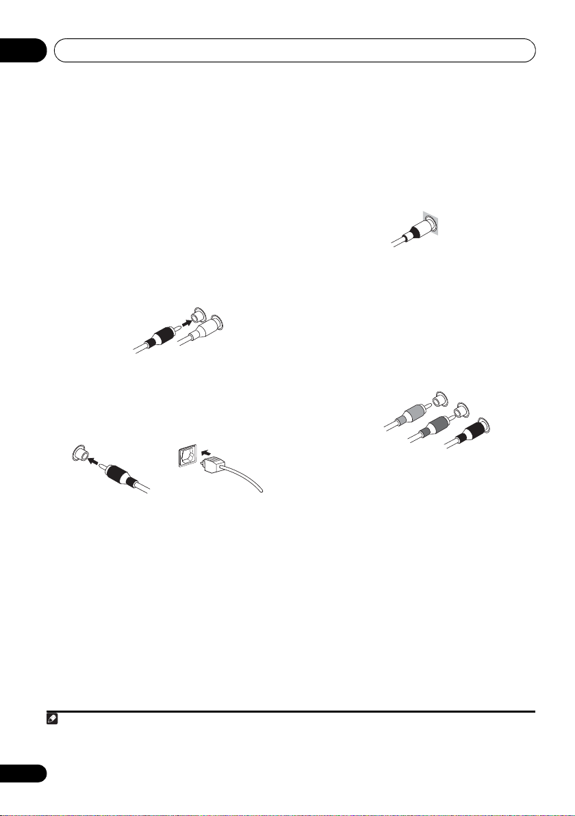
Coaxial digital audio cable Optical cable
S
HDMI, the HDMI logo and High-Definition
Multimedia Interface are trademarks or
registered trademarks of HDMI Licensing, LLC.
“x.v.Color” and x.v.Color logo are trademarks of
Sony Corporation.
Analog audio cables
Use stereo RCA phono cables to connect
analog audio components. These cables are
typically red and white, and you should
connect the red plugs to R (right) terminals
and white plugs to L (left) terminals.
Analog audio cables
Right (red)
Left (white)
Digital audio cables
Commercially available coaxial digital audio
cables or optical cables should be used to
connect digital components to this receiver.
Video cables
Standard RCA video cables
These cables are the most common type of
video connection and are used to connect to
the composite video terminals. The yellow
plugs distinguish them from cables for audio.
tandard RCA video cable
Component video cables
Use component video cables to get the best
possible color reproduction of your video
source. The color signal of the TV is divided into
the luminance (Y) signal and the color (P
P
R) signals and then output. In this way,
interference between the signals is avoided.
Component video cables
1
Green (Y)
Blue (P
B
)
Red (P
R
)
B and
1 • When connecting optical cables, be careful when inserting the plug not to damage the shutter protecting the optical socket.
• When storing optical cable, coil loosely. The cable may be damaged if bent around sharp corners.
• You can also use a standard RCA video cable for coaxial digital connections.
22
En
Page 23
Connecting your equipment 03
English
Français
Deutsch
Nederlands
Italiano
Español
Note
HDMI IN
VIDEO IN
VIDEO
MONITOR OUT
COMPONENT
VIDEO IN
HDMI OUT
COMPONENT VIDEO
MONITOR OUT
PRPBY PRPBY
High picture quality
Terminal for
connection with
source device
Terminal for
connection with TV
monitor
Video signals can be output
This product incorporates copyright protection
technology that is protected by U.S. patents and other
intellectual property rights. Use of this copyright
protection technology must be authorized by Rovi
Corporation, and is intended for home and other limited
viewing uses only unless otherwise authorized by Rovi
Corporation. Reverse engineering or disassembly is
prohibited.
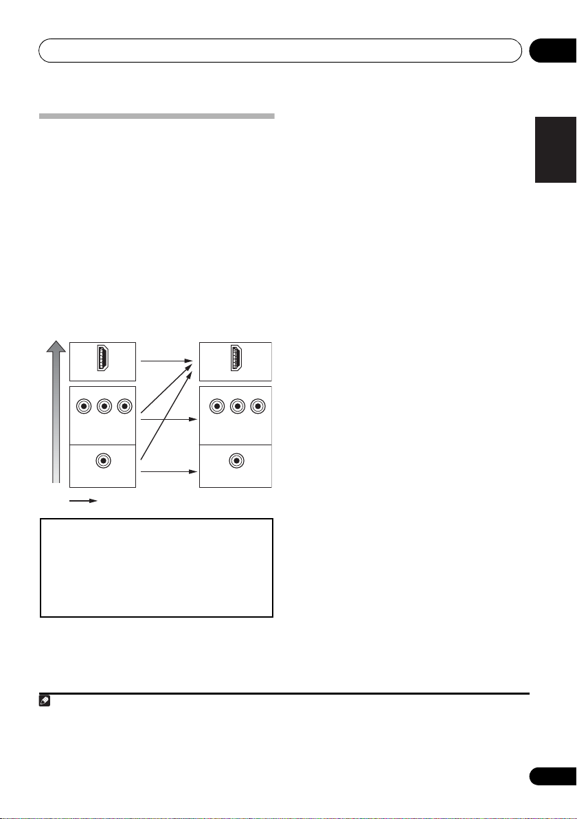
About the video converter
The video converter ensures that all video
sources are output from HDMI OUT terminal.
The only exception is HDMI: since this
resolution cannot be downsampled, you must
connect your monitor/TV to the receiver’s
HDMI video outputs when connecting this
video source.
If several video components are assigned to
the same input function, the converter gives
priority to HDMI, component, then composite
(in that order).
1
1 • If the video signal does not appear on your TV, try adjusting the resolution settings on your component or display. Note that
some components (such as video game units) have resolutions that may not be converted. In this case, try switching Video
Converter OFF (see Video Converter on page 50).
• The signal input resolutions that can be converted from the component video input for the HDMI output are 480i/576i, 480p/
576p, 720p and 1080i. 1080p signal cannot be converted.
23
En
Page 24
Connecting your equipment03
Note
T
Select one
HDMI/DVI-compatible TV
HDMI/DVI-compatible
Blu-ray disc player
1
This connection is
required in order to
listen to the sound of
the TV over the receiver.
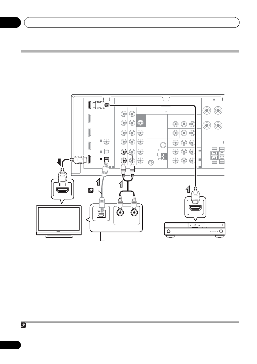
Connecting a TV and playback components
Connecting using HDMI
If you have an HDMI or DVI (with HDCP) equipped component (Blu-ray disc player, etc.), you can
connect it to this receiver using a commercially available HDMI cable.
1
HDMI IN
IN BD
DVD
TV/SAT
DVR/VCR
OUT
HDMI
DIGITAL AUDIO OUT
COAXIAL
IN
(CD)
OPTICAL
IN
IN
(
CD-R/TAPE
OPTICAL
ASSIGNABLE
1
2
1
)
ASSIGNABLE
CD-R/TAPE
L
OUT
R
CD-R/TAPE
L
IN
R
TV/SAT
L
IN
R
1 2
RL
ANALOG AUDIO OUT
DVR/VCR
DVR/VCR
DVD BD
AUDIO
SUBWOOFER
PRE OUT
CD
IN
IN
ADAPTER PORT
(
OUTPUT 5 V 100 mA MAX
ANTENNA
FM
UNBAL
75
SIRIUS
IN
AM
LOOP
)
VIDEO
DVR/VCR
OUT IN
MONITOR OUT
DVD IN BD IN
PRPBY
COMPONENT VIDEO
TV/SAT
IN
MONITOR
OUT
IN
(
DVD
IN
(BD)
ASSIGNABLE
1
HDMI OUT
A
SPEAKERS
FRONT
RL
Class 2 Wiring
FRONT HEIGH
SPEAKERS
RL
2
)
1
2
B
1 If the connection was made using an optical cable, you’ll need to tell the receiver which digital input you connected the TV to
(see Choosing the input signal on page 43).
24
En
Page 25
Connecting your equipment 03
English
Français
Deutsch
Nederlands
Italiano
Español
Note
MONITOR
OUT
RL
DIGITAL AUDIO OUT
ANALOG AUDIO OUT
COAXIAL
VIDEO OUT
OPTICAL
DIGITAL AUDIO OUT
OPTICAL
RL
ANALOG AUDIO OUT
HDMI IN
Select one
TV
DVD player
This connection is
required in order to
listen to the sound of
the TV over the receiver.
Select one
1
2
3
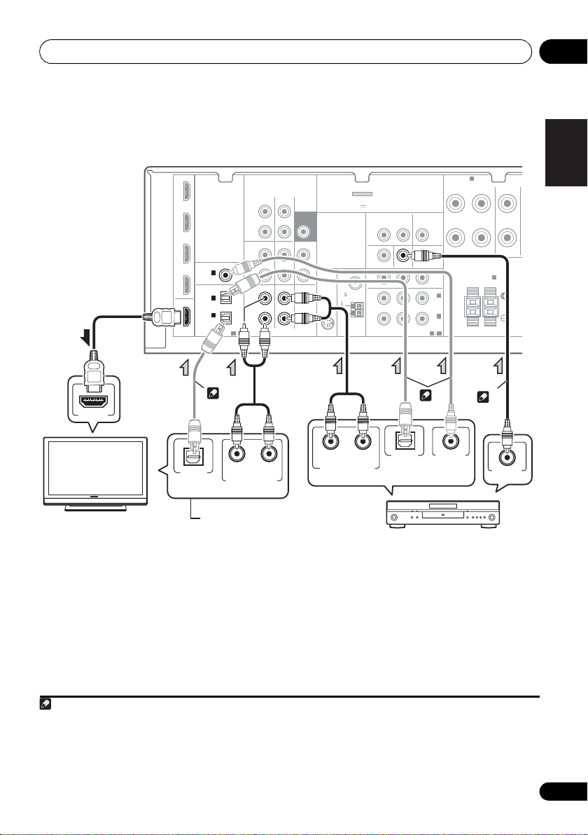
Connecting your DVD player with no HDMI output
This diagram shows connections of a TV (with HDMI input) and DVD player (or other playback
component with no HDMI output) to the receiver.
123
IN BD
DVD
TV/SAT
DVR/VCR
OUT
HDMI
COAXIAL
IN
(CD)
OPTICAL
IN
IN
(
CD-R/TAPE
ASSIGNABLE
1
2
1
)
ASSIGNABLE
A
SPEAKERS
FRONT CENTER
TV/SAT
IN
MONITOR
OUT
IN
(
DVD
IN
(BD)
ASSIGNABLE
1
RL
Class 2 Wiring
FRONT HEIGHT /
SPEAKERS
RL
2
)
1
2
B
CD-R/TAPE
DVR/VCR
L
OUT
R
L
IN
R
L
IN
R
1 2
CD-R/TAPE
TV/SAT
DVR/VCR
DVD BD
AUDIO
SUBWOOFER
PRE OUT
CD
(
OUTPUT 5 V 100 mA MAX
IN
UNBAL
SIRIUS
IN
IN
LOOP
ADAPTER PORT
ANTENNA
FM
75
AM
)
VIDEO
DVR/VCR
OUT IN
MONITOR OUT
DVD IN BD IN
PRPBY
COMPONENT VIDEO
1 If the connection was made using an optical cable, you’ll need to tell the receiver which digital input you connected the TV to
(see Choosing the input signal on page 43).
2 If the connection was made using an optica l or a coaxial cable, you’ll need to tell the receiver which digital input you connected
the DVD player to (see Choosing the input signal on page 43).
3 If your player also has a component video output, you can connect this too. See Using the component video jacks on page 28
for more on this.
25
En
Page 26
Connecting your equipment03
Note
MONITOR
OUT
R
RL
DIGITAL AUDIO OUT
ANALOG AUDIO OUT
COAXIAL
VIDEO OUT
OPTICAL
HDMI OUT
DIGITAL AUDIO OUT
OPTICAL
RL
ANALOG AUDIO OUT
VIDEO IN
Select one
TV
DVD player
This connection is
required in order to listen
to the sound of the TV
over the receiver.
Select one
1
2
3
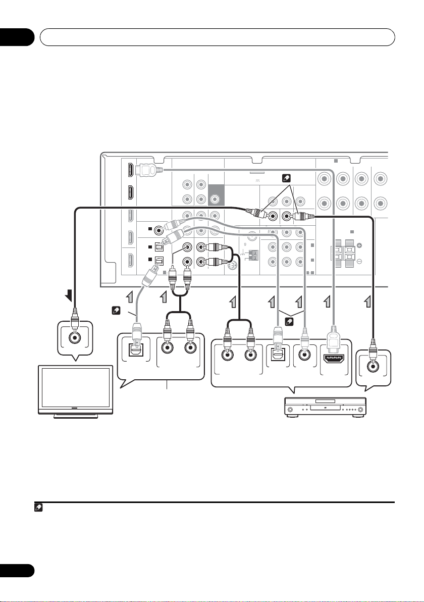
Connecting your TV with no HDMI input
This diagram shows connections of a TV (with no HDMI input) and DVD player (or other playback
component) to the receiver.
• With these connections, the picture is not output to the TV even if the DVD player is connected
with an HDMI cable. Connect the DVD player’s video signals using a composite or component
cord.
123
IN BD
DVD
TV/SAT
DVR/VCR
OUT
HDMI
COAXIAL
IN
(CD)
OPTICAL
IN
IN
(
CD-R/TAPE
ASSIGNABLE
1
2
1
)
ASSIGNABLE
CD-R/TAPE
DVR/VCR
L
OUT
R
CD-R/TAPE
L
IN
R
L
IN
R
1 2
TV/SAT
DVR/VCR
DVD BD
AUDIO
SUBWOOFER
PRE OUT
CD
(
OUTPUT 5 V 100 mA MAX
IN
SIRIUS
IN
IN
ADAPTER PORT
ANTENNA
FM
UNBAL
75
AM
LOOP
)
VIDEO
DVR/VCR
OUT IN
MONITOR OUT
DVD IN BD IN
PRPBY
COMPONENT VIDEO
TV/SAT
IN
MONITOR
ASSIGNABLE
SPEAKERS
RL
Class 2 Wiring
OUT
2
IN
(
)
DVD
1
IN
(BD)
1
2
A
FRONT CENTER
FRONT HEIGHT /
B
SPEAKERS
RL
SUR
R
• Connect using an HDMI cable to listen to HD audio on the receiver. Do not use an HDMI cable
to input video signals.
Depending on the video component, it may not be possible to output signals connected by
HDMI and other methods simultaneously, and it may be necessary to make output settings.
Please refer to the operating instructions supplied with your component for more information.
1 If the connection was made using an optical cable, you’ll need to tell the receiver which digital input you connected the TV to
(see Choosing the input signal on page 43).
2 If the connection was made using an optical or a coaxial cable, you’ll need t o tell the receiver which digital input you connected
the DVD player to (see Choosing the input signal on page 43).
3 If both TV and player has a component video jacks, you can connect these too. See Using the compon ent video jacks on page 28
for more on this.
26
En
Page 27
Connecting your equipment 03
English
Français
Deutsch
Nederlands
Italiano
Español
Note
M
N
DIGITAL AUDIO OUT
OPTICAL
RL
ANALOG AUDIO OUT
VIDEO OUT
Select one
STB
2
1
Select one
DVR, VCR, LD player, etc.
1
2
Connecting a satellite receiver
or other digital set-top box
Satellite and cable receivers, and terrestrial
digital TV tuners are all examples of so-called
‘set-top boxes’.
OAXIAL
ASSIGNABLE
1
IN
(CD)
OPTICAL
2
IN
1
IN
)
D-R/TAPE
ASSIGNABLE
12
CD-R/TAPE
DVR/VCR
L
OUT
R
CD-R/TAPE
L
IN
R
L
IN
R
1 2
TV/SAT
DVR/VCR
DVD BD
AUDIO
SUBWOOFER
PRE OUT
CD
(
OUTPUT 5 V 100 mA MAX
IN
UNBAL
SIRIUS
IN
IN
LOOP
ADAPTER PORT
ANTENNA
FM
75
AM
)
VIDEO
DVR/VCR
OUT IN
MONITOR OUT
DVD IN BD IN
PRPBY
COMPONENT VIDEO
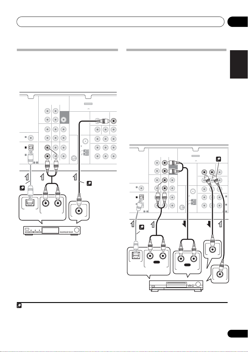
Connecting an HDD/DVD
recorder, VCR and other video
sources
This receiver has audio/video inputs and
outputs suitable for connecting analog or
digital video recorders, including HDD/DVD
recorders and VCRs.
• Only the signals that are input to the
TV/SAT
IN
ASSIG
VIDEO IN terminal can be output from the
VIDEO OUT terminal.
• Audio signals that are input through the
digital terminal will not be output from the
analog terminal.
CD-R/TAPE
COAXIAL
IN
(CD)
OPTICAL
IN
IN
(
CD-R/TAPE
ASSIGNABLE
1
2
1
)
ASSIGNABLE
DVR/VCR
L
OUT
R
CD-R/TAPE
DVR/VCR
L
IN
R
DVD BD
TV/SAT
L
IN
R
1 2
AUDIO
SUBWOOFER
PRE OUT
CD
IN
IN
(
OUTPUT 5 V 100 mA MAX
UNBAL
75
SIRIUS
IN
LOOP
ADAPTER PORT
ANTENNA
FM
AM
)
VIDEO
DVR/VCR
OUT IN
MONITOR OUT
DVD IN BD IN
PRPBY
COMPONENT VIDEO
TV/SAT
IN
MONITOR
MONITOR
OUT
OUT
IN
(
DVD
IN
(BD)
ASSIGNABLE
1 2
2
)
1
OPTICAL
DIGITAL
AUDIO OUT
RL
PLAY
ANALOG AUDIO OUT
RL
REC
ANALOG AUDIO IN
1 If the connection was made using an optical cable, you’ll need to tell the receiver which digital input you connected the set-
top box or video component to (see Choosing the input signal on page 43).
2 If the set-top box or video component also has an HDMI or a component video output, you can connect this too. See Connecting
using HDMI on page 24 or Using the component video jacks on page 28 for more on this.
VIDEO IN
VIDEO OUT
27
En
Page 28
Connecting your equipment03
s
BD player
TV
Note
M
N
PLAY
R
L
DIGITAL AUDIO OUT
ANALOG AUDIO OUT
COAXIAL
R
L
ANALOG AUDIO IN
REC
OPTICAL
Select one
CD-R, MD, DAT, Tape recorder, etc.
2
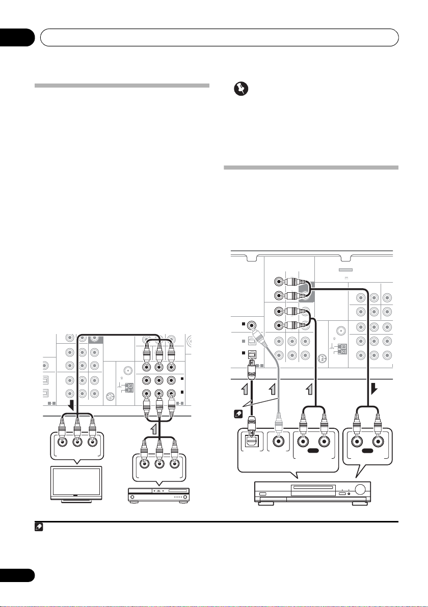
Using the component video
jacks
Component video should deliver superior
picture quality when compared to composite
video. A further advantage (if your source and TV
are both compatible) is progressive-scan video,
which delivers a very stable, flicker-free picture.
See the manuals that came with your TV and
source component to check whether they are
compatible with progressive-scan video.
• If necessary, assign the component video
inputs to the input source you’ve connected.
This only needs to be done if you didn’t connect
according to the following defaults:
• COMPONENT VIDEO IN 1 – BD
• COMPONENT VIDEO IN 2 – DVD
See The Input Assign menu on page 48 for
more on this.
• For the audio connection, refer to
Connecting your DVD player with no HDMI
output
on page 25.
R
CD-R/TAPE
DVR/VCR
IGNABLE
IGNABLE
1 2
IN
IN
L
R
L
R
TV/SAT
DVD BD
AUDIO
CD
IN
IN
SIRIUS
IN
ANTENNA
FM
UNBAL
75
AM
LOOP
MONITOR OUT
DVD IN BD IN
PRPBY
COMPONENT VIDEO
MONITOR
OUT
IN
(
DVD
IN
(BD)
ASSIGNABLE
1 2
Clas
2
)
1
Important
• If you connect any source component to
the receiver using a component video
input, you must also have your TV
connected to this receiver’s COMPONENT
VIDEO OUT jacks.
Connecting other audio
components
The number and kind of connections depends
on the kind of component you’re connecting.
Follow the steps below to connect a CD-R, MD,
DAT, tape recorder or other audio component.
CD-R/TAPE
COAXIAL
IN
(CD)
OPTICAL
IN
IN
(
CD-R/TAPE
ASSIGNABLE
1
2
1
)
ASSIGNABLE
DVR/VCR
L
OUT
R
L
IN
R
L
IN
R
1 2
CD-R/TAPE
TV/SAT
DVR/VCR
DVD BD
AUDIO
SUBWOOFER
PRE OUT
CD
(
OUTPUT 5 V 100 mA MAX
IN
SIRIUS
IN
IN
ADAPTER PORT
ANTENNA
FM
UNBAL
75
AM
LOOP
)
VIDEO
DVR/VCR
OUT IN
MONITOR OUT
DVD IN BD IN
PRPBY
COMPONENT VIDEO
TV/SAT
IN
ASSIG
1
2
RYPB
P
COMPONENT VIDEO IN
1 Note that you must connect digital components to analog audio jacks if you want to record to/from digital components (like
an MD) to/from analog components.
2 If the connection was made using an optical or a coaxial cable, you’ll need t o tell the receiver which digital input you connected
the component to (see Choosing the input signal on page 43).
28
En
P
COMPONENT VIDEO OUT
RYPB
Page 29
Connecting your equipment 03
English
Français
Deutsch
Nederlands
Italiano
Español
F connector
ANTENNA
FM
UNBAL
75
Ω
AM
LOOP
Outdoor
antenna
5 m to 6 m
(15 ft. to 18 ft.)
Indoor antenna
(vinyl-coated wire)
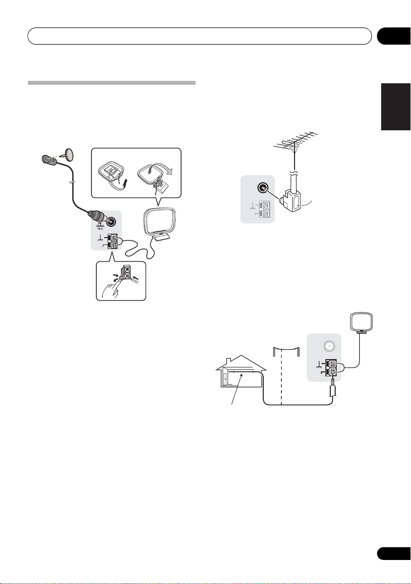
Using external antennas
Connecting antennas
Connect the AM loop antenna and the FM wire
antenna as shown below. To improve reception
and sound quality, connect external antennas
(see Using external antennas below).
fig. a fig. b
4
ANTENNA
2
To improve FM reception
Use an F connector (not supplied) to connect
an external FM antenna.
ANTENNA
FM
UNBAL
75
Ω
AM
LOOP
AM
LOOP
1 Push open the tabs, then insert one wire
fully into each terminal, then release the tabs
to secure the AM antenna wires.
2 Fix the AM loop antenna to the attached
stand.
To fix the stand to the antenna, bend in the
direction indicated by the arrow (fig. a) then
clip the loop onto the stand (fig. b).
3 Place the AM antenna on a flat surface
and in a direction giving the best reception.
4 Connect the FM wire antenna into the FM
antenna socket.
For best results, extend the FM antenna fully
and fix to a wall or door frame. Don’t drape
loosely or leave coiled up.
3
Connect a 5 m to 6 m (15 ft. to 18 ft.) length of
vinyl-coated wire to the AM antenna terminal
without disconnecting the supplied AM loop
To improve AM reception
1
antenna.
For the best possible reception, suspend
horizontally outdoors.
29
En
Page 30
Connecting your equipment03
MASTER
VOLUME
MCACC
SETUP MIC
VIDEO INPUT
AUDIOLRVIDEO
iPod
iPhone
USB
CONTROL ON / OFF
LVIDEO
R
AUDIO/VIDEO OUTPUT
This receiver
Video camera
(etc.)
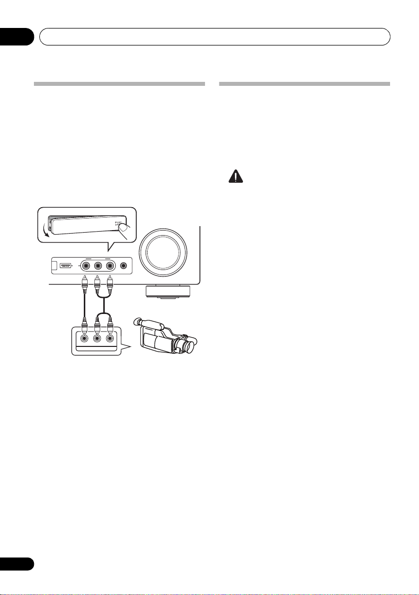
Connecting to the front panel
video terminal
Front video connections are accessed via the
front panel using the INPUT SELECTOR or
VIDEO button on the remote control. There are
standard audio/video jacks. Hook them up the
same way you made the rear panel
connections.
•Push down on the PUSH OPEN tab to
access the front video connections.
Plugging in the receiver
Only plug in after you have connected all your
components to this receiver, including the
speakers.
• Plug the AC power cord into a convenient
AC power outlet.
CAUTION
• Handle the power cord by the plug part. Do
not pull out the plug by tugging the cord,
and never touch the power cord when your
hands are wet, as this could cause a short
circuit or electric shock. Do not place the
unit, a piece of furniture, or other object on
the power cord or pinch the cord in any
other way. Never make a knot in the cord or
tie it with other cables. The power cords
should be routed so that they are not likely
to be stepped on. A damaged power cord
can cause a fire or give you an electric
shock. Check the power cord once in a
while. If you find it damaged, ask your
nearest Pioneer authorized independent
service company for a replacement.
• The receiver should be disconnected by
removing the mains plug from the wall
socket when not in regular use, e.g., when
on vacation.
30
En
Page 31

Basic Setup 04
English
Français
Deutsch
Nederlands
Italiano
Español
ENTER
MUTE
RETURN
AUDIO
PARAMETER
TUNER EDIT
TOOLS
MASTER
VOLUME
iPod CTRL
CATEGORY
BAND
MENU
HOME
MENU
SETUP
TOP
MENU
T
U
N
E
T
U
N
E
P
R
E
S
E
T
P
R
E
S
E
T
MASTER
VOLUME
MCACC
SETUP MIC
VIDEO INPUT
AUDIOLRVIDEO
iPod
iPhone
USB
CONTROL ON / OFF
Tripod
Microphone
Chapter 4:
Basic Setup
Automatically setting up for
surround sound (MCACC)
The Auto Multi-Channel Acoustic Calibration
(MCACC) setup measures the acoustic
characteristics of your listening area, taking
into account ambient noise, speaker size and
distance, and tests for both channel delay and
channel level. After you have set up the
microphone provided with your system, the
receiver uses the information from a series of
test tones to optimize the speaker settings and
equalization for your particular room.
CAUTION
• The test tones used in the Auto MCACC
Setup are output at high volume.
Important
• The Auto MCACC Setup will overwrite any
existing speaker settings you’ve made.
• Before using the Auto MCACC Setup, the
iPod USB function should not be selected
as an input source.
• When both the surround back speaker and
the front height speaker are connected,
conduct Auto MCACC setup twice: once
with the Speaker System setting is in
‘Surr.Back’ and once with the Speaker
System setting is in ‘Height’. (There is no
need to conduct Auto MCACC Setup every
time the Speaker System setting is
changed.)
RECEIVER
RECEIVER
BD DVD
INPUT SELECT
TV
CONTROL
SOURCESLEEP
INPUT
TV
1 Switch on the receiver and your TV.
Switch the TV input so that it connects to the
receiver.
2 Connect the microphone to the MCACC
SETUP MIC jack on the front panel.
Make sure there are no obstacles between the
speakers and the microphone.
If you have a tripod, use it to place the
microphone so that it’s about ear level at your
normal listening position. Otherwise, place the
microphone at ear level using a table or a chair.
31
En
Page 32

Basic Setup04
Note
System Setup
1.Auto MCACC
2.Manual SP Setup
3.Input Assign
4.Speaker System
5.Video Parameter
Return
3 Press on the remote control,
then press the
RECEIVER
SETUP
button.
An on-screen display (OSD) appears on your
TV. Use /// and ENTER on the remote
control to navigate through the screens and
select menu items. Press RETURN to exit the
current menu.
• Press SETUP at any time to exit the System
Setup menu.
4 Select ‘Auto MCACC’ from the System
Setup menu then press ENTER.
1
2
Try to be as quiet as possible after pressing
ENTER. The system outputs a series of test
tones to establish the ambient noise level.
5 Follow the instructions on-screen.
• Make sure the microphone is connected.
• Make sure the subwoofer is on and the
volume is turned up.
• See below for notes regarding background
noise and other possible interference.
6 Wait for the test tones to finish.
A progress report is displayed on-screen while
the receiver outputs test tones to determine the
speakers present in your setup. Try to be as
quiet as possible while it’s doing this.
1.Auto MCACC
Now Analyzing
Environment Check
Ambient Noise
Speaker YES/NO
Return
• For correct speaker settings, do not adjust
the volume during the test tones.
7 Confirm the speaker configuration.
The configuration shown on-screen should
reflect the actual speakers you have.
• With error messages (such as Too much
ambient noise) select RETRY after
checking for ambient noise (see Other
problems when using the Auto MCACC
Setup on page 33).
1.Auto MCACC
Check!
[ YES ]
Front
[ YES ]
Center
[ YES ]
Surr
[YESx2]
Surr. Back
[ YES ]
Subwoofer
10:Next
OK
Return
32
En
If the speaker configuration displayed isn’t
correct, use / to select the speaker and
/ to change the setting. When you’re
finished, go to the next step.
If you see an error message (ERR) in the right
side column, there may be a problem with the
speaker connection. If selecting RETRY
doesn’t fix the problem, turn off the power and
check the speaker connections.
1 The screensaver automatically starts after three minutes of inactivity. If you cancel the Auto MCACC Setup at any time, the
receiver automatically exits and no settings will be made.
2 MIC IN blinks when the microphone is not connected to MCACC SETUP MIC.
Page 33

Basic Setup 04
English
Français
Deutsch
Nederlands
Italiano
Español
Note
1.Auto MCACC
Now Analyzing
Surround Analyzing
Speaker System
Speaker Distance
Channel Level
Acoustic Cal EQ
Return
8 Make sure ‘OK’ is selected, then press
ENTER.
If the screen in step 7 is left untouched for 10
seconds and the ENTER button is not pressed
in step 8, the Auto MCACC setup will start
automatically as shown below.
A progress report is displayed on-screen while
the receiver outputs more test tones to
determine the optimum receiver settings for
channel level, speaker distance, and Acoustic
Calibration EQ.
Again, try to be as quiet as possible while this
is happening. It may take 1 to 3 minutes.
9 The Auto MCACC Setup has finished!
You return to the System Setup menu.
The settings made in the Auto MCACC Setup
should give you excellent surround sound from
your system, but it is also possible to adjust
these settings manually using the System
Setup menu (starting on page 44).
Other problems when using the
Auto MCACC Setup
If the room environment is not optimal for the
Auto MCACC Setup (too much background
noise, echo off the walls, obstacles blocking
the speakers from the microphone) the final
settings may be incorrect. Check for
household appliances (air conditioner, fridge,
fan, etc.), that may be affecting the
environment and switch them off if necessary.
If there are any instructions showing in the
front panel display, please follow them.
• Some older TVs may interfere with the
operation of the microphone. If this seems
to be happening, switch off the TV when
doing the Auto MCACC Setup.
1
1 • Depending on the characteristics of your room, sometimes identical speakers with cone sizes of around 12 cm (5 inches)
will end up with different size settings. You can correct the setting manually using the Speaker Setting on page 45.
• The subwoofer distance setting may be farther than the actual distance from the listening position. This setting should be
accurate (taking delay and room characteristics into account) and generally does not need to be changed.
33
En
Page 34

Listening to your system05
Note
Chapter 5:
Listening to your system
Important
• The listening modes and many features
described in this section may not be
available depending on the current source,
settings and status of the receiver.
Basic playback
Here are the basic instructions for playing a
source (such as a DVD disc) with your home
theater system.
1 Switch on your system components and
receiver.
Start by switching on the playback component
(for example a DVD player), your TV
subwoofer (if you have one), then the receiver
(press RECEIVER).
• Make sure the setup microphone is
disconnected.
2 Select the input function you want to
play.
You can use the input function buttons on the
remote control, INPUT SELECT, or the front
panel INPUT SELECTOR dial.
3 Press AUTO/DIRECT to select ‘AUTO
SURROUND’ and start playback of the source.
If you’re playing a Dolby Digital or DTS
surround sound DVD disc, you should hear
surround sound. If you are playing a stereo
source, you will only hear sound from the front
left/right speakers in the default listening
mode.
1
and
2
It is possible to check on the front panel display
whether or not surround sound playback is
being performed properly.
When using a surround back speaker,
2D+PLIIx is displayed when playing Dolby
Digital 5.1-channel signals, and DTS+NEO:6 is
displayed when playing DTS 5.1-channel
signals.
When not using a surround back speaker, 2D
is displayed when playing Dolby Digital
signals.
If the display does not correspond to the input
signal and listening mode, check the
connections and settings.
4 Use the volume control to adjust the
volume level.
Turn down the volume of your TV so that all
sound is coming from the speakers connected
to this receiver.
3
1 Make sure that the TV’s video input is set to this receiver (for example, if you connected this receiver to the VIDEO jacks on
your TV, make sure that the VIDEO input is now selected).
2 If you need to manually switch the input signal type press SIGNAL SEL (page 43).
3 • You may need to check the digital audio output settings on your DVD player or digital satellite receiver. It should be set to
output Dolby Digital, DTS and 88.2 kHz / 96 kHz PCM (2 channel) audio, and if there is an MPEG audio option, set this to convert
the MPEG audio to PCM.
• Depending on your DVD player or source discs, you may only get digital 2 channel stereo and analog sound. In this case, the
receiver must be set to a multichannel listening mode if you want multichannel surround sound.
34
En
Page 35

Listening to your system 05
English
Français
Deutsch
Nederlands
Italiano
Español
Note
BD MENU
STANDARD
ADV SURR
STEREO/
A.L.C.
AUTO/
DIRECT
• While listening to a source, press
Auto playback
The simplest, most direct listening option is the
Auto Surround feature. With this, the receiver
automatically detects what kind of source
you’re playing and selects multichannel or
stereo playback as necessary.
STEREO/
AUTO/
A.L.C.
DIRECT
• While listening to a source, press
AUTO/DIRECT
2
for auto playback of a
STANDARD
1
BD MENU
ADV SURR
source.
Press repeatedly until AUTO SURROUND
shows briefly in the display (it will then show
the decoding or playback format). Check the
digital format indicators in the display to see
how the source is being processed.
Listening in surround sound
Using this receiver, you can listen to any source
in surround sound. However, the options
available will depend on your speaker setup and
the type of source you’re listening to.
The following modes provide basic surround
sound for stereo and multichannel sources.
STANDARD.
If the source is Dolby Digital, DTS, or Dolby
Surround encoded, the proper decoding
format will automatically be selected and
shows in the display.
When the surround back and front height
speaker are not connected.
With two channel sources, you can select from:
• DOLBY PLII MOVIE – Up to 5.1 channel
sound, especially suited to movie sources
• DOLBY PLII MUSIC
3
– Up to 5.1 channel
sound, especially suited to music sources
• DOLBY PLII GAME – Up to 5.1 channel
sound, especially suited for video games
• NEO:6 CINEMA – Up to 5.1 channel
sound, especially suited to movie sources
• NEO:6 MUSIC – Up to 5.1 channel sound,
especially suited to music sources
• DOLBY PRO LOGIC – 4.1 channel
surround sound
When the front height speaker is connected.
With two channel sources, you can select from:
• DOLBY PLII MOVIE – See above
• DOLBY PLII MUSIC – See above
• DOLBY PLII GAME – See above
• DOLBY PLIIz HEIGHT – Up to 7.1 channel
sound
5
• NEO:6 CINEMA – See above
• NEO:6 MUSIC – See above
• DOLBY PRO LOGIC – See above
• Straight Decode – Plays back without the
DOLBY PLII, DOLBY PLIIz HEIGHT and
NEO:6 effects.
4
1 Stereo surround (matrix) formats are decoded accordingly using NEO:6 CINEMA or DOLBY PLIIx MOVIE (see Listening in
surround sound above for more on these decoding formats).
2 For more options using this button, see Using Stream Direct on page 38.
3 When listening to 2-channel sources in DOLBY PLII MUSIC mode, there are three further parameters you can adjust:
C.WIDTH, DIMEN., and PNRM.. See Setting the Audio options on page 40 to adjust them.
4 When listening to 2-channel sources in NEO:6 CINEMA or NEO:6 MUSIC mode, you can also adjust the C.IMG effect (see
Setting the Audio options on page 40).
5 When listening to 2-channel sources in DOLBY PLIIz HEIGHT mode, you can also adjust the H.GAIN effect (see Setting the
Audio options on page 40).
35
En
Page 36

Listening to your system05
Note
With multichannel sources, you can select
from:
• DOLBY PLIIz HEIGHT – Up to 7.1 channel
sound
1
• Straight Decode – Plays back without the
DOLBY PLIIz HEIGHT effects.
When the surround back speaker is
connected.
2
If you connected surround back speakers, see
also Using surround back channel processing
on page 39.
With two channel sources, you can select from:
• DOLBY PLIIx MOVIE – Up to 7.1 channel
sound, especially suited to movie sources
• DOLBY PLIIx MUSIC – Up to 7.1 channel
sound, especially suited to music sources
• DOLBY PLIIx GAME – Up to 7.1 channel
sound, especially suited to video games
• NEO:6 CINEMA – Up to 6.1 channel sound,
especially suited to movie sources
• NEO:6 MUSIC – Up to 6.1 channel sound,
especially suited to music sources
4
• DOLBY PRO LOGIC – 4.1 channel
surround sound (sound from the surround
speakers is mono)
With multichannel sources, if you have
connected surround back speaker(s) and have
selected SB ON, you can select (according to
format):
• DOLBY PLIIx MOVIE – See above (only
available when you’re using two surround
back speakers)
• DOLBY PLIIx MUSIC – See above
• DOLBY DIGITAL EX – Creates surround
back channel sound for 5.1 channel
sources and provides pure decoding for
6.1 channel sources (like Dolby Digital
Surround EX)
• DTS-ES – Allows you to hear 6.1 channel
playback with DTS-ES encoded sources
• DTS NEO:6 –
Allows you to hear 6.1 channel
playback with DTS encoded sources
Using the Advanced surround effects
The Advanced surround feature creates a
variety of surround effects. Try different modes
with various soundtracks to see which you like.
STANDARD
BD MENU
ADV SURR
STEREO/
AUTO/
A.L.C.
3
DIRECT
• Press ADV SURR repeatedly to select a
listening mode.
• ACTION – Designed for action movies with
dynamic soundtracks.
• DRAMA – Designed for movies with lots of
dialog.
• ENT.SHOW –
Suitable for musical sources.
• ADVANCED GAME – Suitable for video
games.
• SPORTS – Suitable for sports programs.
• CLASSICAL – Gives a large concert halltype sound.
• ROCK/POP – Creates a live concert sound
for rock and/or pop music.
• UNPLUGGED – Suitable for acoustic
music sources.
• EXT.STEREO –
Gives multichannel sound to
a stereo source, using all of your speakers.
1 When listening to 2-channel sources in DOLBY PLIIz HEIGHT mode, you can also adjust the H.GAIN effect (see Setting the
Audio options on page 40).
2 • If surround back channel processing (page 39) is switched off, or the surround back speakers are set to NO, DOLBY PLIIx
becomes DOLBY PLII (5.1 channel sound).
• In modes that give 6.1 channel sound, the same signal is heard from both surround back speakers.
3 When listening to 2-channel sources in DOLBY PLIIx MUSIC mode, there are three further parameters you can adjust:
C.WIDTH, DIMEN., and PNRM.. See Setting the Audio options on page 40 to adjust them.
4 When listening to 2-channel sources in NEO:6 CINEMA or NEO:6 MUSIC mode, you can also adjust the C.IMG effect
(see Setting the Audio options on page 40).
36
En
Page 37

Listening to your system 05
English
Français
Deutsch
Nederlands
Italiano
Español
BD MENU
STANDARD
ADV SURR
AUTO/
DIRECT
STEREO/
A.L.C.
F.S.S.ADVANCE
position
Front left
speaker
Front right
speaker
Listening in stereo
When you select STEREO you will hear the
source through just the front left and right
speakers (and possibly your subwoofer
depending on your speaker settings). Dolby
Digital and DTS multichannel sources are
downmixed to stereo.
In the Auto level control stereo mode (ALC),
this unit equalizes playback sound levels if
each sound level varies with the music source
recorded in a portable audio player.
AUTO/
STEREO/
DIRECT
A.L.C.
• While listening to a source, press
STEREO/A.L.C. for stereo playback.
Press repeatedly to switch between:
• STEREO – The audio is heard with your
surround settings and you can still use the
Midnight, Loudness, Phase Control, Sound
Retriever and Tone functions.
• ALC – Listening in Auto level control stereo
mode.
• F.S.S.ADVANCE – See Using Front Stage
Surround Advance below for more on this.
STANDARD
BD MENU
ADV SURR
Using Front Stage Surround
Advance
The Front Stage Surround Advance function
allows you to create natural surround sound
effects using just the front speakers and the
subwoofer.
• While listening to a source, press
STEREO/A.L.C. to select Front Stage
Surround Advance modes.
• STEREO – See Listening in stereo above for
more on this.
• ALC – See Listening in stereo above for
more on this.
• F.S.S.ADVANCE – Use to provide a rich
surround sound effect directed to the
center of where the front left and right
speakers sound projection area
converges.
37
En
Page 38

Listening to your system05
Note
BD MENU
STANDARD
ADV SURR
STEREO/
A.L.C.
AUTO/
DIRECT
RECEIVER
Using Stream Direct
Use the Stream Direct modes when you want
to hear the truest possible reproduction of a
source. All unnecessary signal processing is
bypassed.
• While listening to a source, press AUTO/
DIRECT to select Stream Direct mode.
• AUTO SURROUND – See Auto playback on
page 35.
• DIRECT – Sources are heard according to
the settings made in the Surround Setup
(speaker setting, channel level, speaker
distance), as well as with dual mono
settings.
1
You will hear sources according
to the number of channels in the signal.
• PURE DIRECT – Analog and PCM sources
are heard without any digital processing.
Using the Sound Retriever
When audio data is removed during the
compression process, sound quality often
suffers from an uneven sound image. The
Sound Retriever feature employs new DSP
technology that helps bring CD quality sound
back to compressed 2-channel audio by
restoring sound pressure and smoothing
jagged artifacts left over after compression.
HDD
DVD
1
RECEIVER
RECEIVER
SOURCESLEEP
INPUT SELECT
TV
CONTROL
INPUT
S.RETRIEVER
4
MIDNIGHT
7
DIMMER
2
SB CH
5
SPEAKERS
8
CH SELECT
2
VCR
DISP
3
EQ
CH
6
PHASE
LEV
CH
9
SHIFT
LEV
Better sound using Phase Control
This receiver’s Phase Control feature uses
phase correction measures to make sure your
sound source arrives at the listening position in
phase, preventing unwanted distortion and/or
coloring of the sound (see illustration below).
During multichannel playback, LFE (LowFrequency Effects) signals as well as lowfrequency signals in each channel are
assigned to the subwoofer or other the
subwoofer and the most appropriate speaker.
At least in theory, however, this type of
processing involves a group delay that varies
with frequency, resulting in phase distortion
where the low-frequency sound is delayed or
muffled by the conflict with other channels.
With the Phase Control mode switched on, this
receiver can reproduce powerful bass sound
without deteriorating the quality of the original
sound (see illustration below).
P
H
A
S
E
C
O
N
T
R
O
L
O
F
F
P
H
A
S
E
C
O
N
T
R
O
L
O
N
Sound
source
Sound
source
Front speaker
Subwoofer
Front speaker
Subwoofer
Listening
position
Listening
position
?
38
En
• Press , then press
S.RETRIEVER
to switch the sound retriever on or off.
1In the DIRECT mode, Phase Control, Acoustic Calibration EQ, Sound Delay, Auto Delay, LFE Attenuate and Center image
functions are available.
2 The Sound Retriever is only applicable to 2-channel sources.
Page 39

Listening to your system 05
English
Français
Deutsch
Nederlands
Italiano
Español
Note
INPUT SELECT
SOURCESLEEP
TV
CONTROL
INPUT
RECEIVER
RECEIVER
DIMMER
1
4
7
MIDNIGHT
S.RETRIEVER
HDD
2
5
8
SPEAKERS
LEV
LEV
SB CH
DISP
EQ
PHASE
DVD
3
6
9
CH
CH
CH SELECT
VCR
SHIFT
RECEIVER
INPUT SELECT
SOURCESLEEP
TV
CONTROL
INPUT
RECEIVER
RECEIVER
DIMMER
1
4
7
MIDNIGHT
S.RETRIEVER
HDD
2
5
8
SPEAKERS
LEV
LEV
SB CH
DISP
EQ
PHASE
DVD
3
6
9
CH
CH
CH SELECT
VCR
SHIFT
RECEIVER
DIMMER
1
4
7
MIDNIGHT
S.RETRIEVER
HDD
2
5
8
SPEAKERS
LEV
LEV
SB CH
DISP
EQ
PHASE
DVD
3
6
9
CH
CH
CH SELECT
VCR
SHIFT
Phase Control technology provides coherent
sound reproduction through the use of phase
matching
1
for an optimal sound image at your
listening position. The default setting is on and
we recommend leaving Phase Control
switched on for all sound sources.
• Press , then press
PHASE
switch the Phase Control on or off.
Listening with Acoustic
Calibration EQ
You can listen to sources using the Acoustic
Calibration Equalization set in Automatically
setting up for surround sound (MCACC) on
page 31. Refer to these pages for more on
Acoustic Calibration Equalization.
to
Using surround back channel
processing
You can have the receiver automatically use
6.1 or 7.1 decoding for 6.1 encoded sources
(for example, Dolby Digital EX or DTS-ES), or
you can choose to always use 6.1 or 7.1
decoding (for example, with 5.1 encoded
material). With 5.1 encoded sources, a
surround back channel will be generated, but
the material may sound better in the 5.1
format for which it was originally encoded (in
which case, you can simply switch surround
back channel processing off).
• With a 7.1-channel surround system,
audio signals that have undergone matrix
decoding processing through surround
back channel processing to which the Up
Mix function is added are output from the
surround back speakers.
RECEIVER
RECEIVER
INPUT SELECT
TV
CONTROL
SOURCESLEEP
INPUT
• While listening to a source, press
Acoustic Calibration EQ on or off.
, then press EQ to switch the
The MCACC indicator on the front panel lights
when Acoustic Calibration EQ is active.
• Press , then press SB CH
repeatedly to cycle the surround back
channel options.
Each press cycles through the options as
follows:
2
• SB ON –
RECEIVER
Matrix decoding processing for
generating the surround back component
from the surround component is turned on.
1 Phase matching is a very important factor in achieving proper sound reproduction. If two waveforms are ‘in phase’, they crest
and trough together, resulting in increased amplitude, clarity and presence of the sound signal. If a crest of a wave meets a
trough (as shown in the upper section of the diagram above) then the sound will be ‘out of phase’ and an unreliable sound
image will be produced.
• If your subwoofer has a phase control switch, set it to the plus (+) sign (or 0°). However, the effect you can actually feel when
PHASE CONTROL is set to ON on this receiver depends on the type of your subwoofer. Set your subwoofer to maximize the
effect. It is also recommended you try changing the orientation or the place of your subwoofer.
• Set the built-in lowpass filter switch of your subwoofer to OFF. If this cannot be done on your subwoofer, set the cutoff
frequency to a higher value.
• If the speaker distance is not properly set, you may not have a maximized PHASE CONTROL effect.
• The PHASE CONTROL mode cannot be set to ON in the following cases:
– When the PURE DIRECT mode is switched on.
– When the headphones are connected.
2 You can’t use Acoustic Calibration EQ with Stream Direct mode and it has no effect with headphones.
39
En
Page 40

Listening to your system05
Note
C
SW
L R
SL SR
SBL SBR SBL SBR
C
SW
L R
SL SR
UP MIX OFF UP MIX ON
ENTER
RETURN
AUDIO
PARAMETER
TUNER EDIT
TOOLS
MASTER
VOLUME
iPod CTRL
BAND
MENU
HOME
MENU
SETUP
TOP
MENU
T
U
N
E
T
U
N
E
P
R
E
S
E
T
P
R
E
S
E
T
RECEIVER
• SB AUTO – Matrix decoding processing for
generating the surround back component
from the surround component is switched
automatically. Matrix decoding processing
is only performed when surround back
channel signals are detected in the input
signals.
• SB OFF – Matrix decoding processing for
generating the surround back component
from the surround component is turned
off.
Setting the Up Mix function
In a 7.1-channel surround system with
surround speakers placed directly at the sides
of the listening position, the surround sound of
5.1-channel sources is heard from the side. The
Up Mix function mixes the sound of the
surround speakers with the surround back
speakers so that the surround sound is heard
from diagonally to the rear as it should be.
• Using the Up Mix function is effective when
the speakers in the 7.1-channel surround
system are set up as recommended in the
example on page 17.
• Depending on the positions of the speakers
and the sound source, in some cases it
may not be possible to achieve good
results. In this case, set the setting to OFF.
1 Switch the receiver into standby.
40
En
1• Set to ON regardless of this setting when playing DTS-HD signals.
• May automatically be set to OFF even when set to ON, depending on the input signal and listening mode.
2 While holding down the
the front panel, and hold the
ON
for about two seconds.
PRESET
STANDBY/
on
UP MIX: OFF appears and the Up Mix function
turns off. If you want to turn this function on,
perform steps 1 and 2 again.
•When set to ON, the (Up Mix) indicator
on the front panel lights.
Setting the Audio options
There are a number of additional sound
settings you can make using the AUDIO
PARAMETER menu. The defaults, if not stated,
are listed in bold.
Important
• Note that if a setting doesn’t appear
1
in the AUDIO PARAMETER menu, it is
unavailable due to the current source,
settings and status of the receiver.
RECEIVER
RECEIVER
BD DVD
INPUT SELECT
TV
CONTROL
SOURCESLEEP
INPUT
TV
1 Press on the remote control,
then press
2Use
AUDIO PARAMETER
/
to select the setting you want to
button.
adjust.
Depending on the current status/mode of the
receiver, certain options may not be able to be
selected. Check the table below for notes on
this.
3Use
/
to set it as necessary.
See the table below for the options available for
each setting.
4Press
RETURN
to confirm and exit the
menu.
Page 41

Listening to your system 05
English
Français
Deutsch
Nederlands
Italiano
Español
Setting What it does Option(s)
EQ
(Acoustic Calibration
EQ)
S.DELAY
(Sound Delay)
MIDNIGHT
LOUDNESS
b
S.RTV
(Sound Retriever)
DUAL MONO
DRC
(Dynamic Range
Control)
LFE ATT
(LFE Attenuate)
SACD G.
(SACD Gain)
HDMI
(HDMI Audio)
a
a
d
f
Switches on/off the effect of Acoustic Calibration EQ. ON
OFF
Some monitors have a slight delay when showing video, so
the soundtrack will be slightly out of sync with the picture.
By adding a bit of delay, you can adjust the sound to match
the presentation of the video.
Allows you to hear effective surround sound of movies at
low volumes.
Used to get good bass and treble from music sources at
low volumes.
When audio data is removed during the WMA/MP3
compression process, sound quality often suffers from an
uneven sound image. The Sound Retriever feature employs
new DSP technology that helps bring CD quality sound
back to compressed 2-channel audio by restoring sound
pressure and smoothing jagged artifacts left over after
compression.
Specifies how dual mono encoded Dolby Digital
soundtracks should be played.
Adjusts the level of dynamic range for movie soundtracks
optimized for Dolby Digital, DTS, Dolby Digital Plus, Dolby
TrueHD, DTS-HD and DTS-HD Master Audio (you may
need to use this feature when listening to surround sound
at low volumes).
Some Dolby Digital and DTS audio sources include ultralow bass tones. Set the LFE attenuator as necessary to
prevent the ultra-low bass tones from distorting the sound
from the speakers.
The LFE is not limited when set to 0 dB, which is the
recommended value. When set to –15 dB, the LFE is
limited by the respective degree. When OFF is selected, no
sound is output from the LFE channel.
Brings out detail in SACDs by maximizing the dynamic
range (during digital processing).
Specifies the routing of the HDMI audio signal out of this
receiver (amp) or through to a TV or flat panel TV. When
THRU is selected, no sound is output from this receiver.
c
0.0 to 9.0 (frames)
1 second = 30 frames
(NTSC)
Default: 0.0
M/L OFF
MIDNIGHT
LOUDNESS
OFF
ON
CH1 –
Channel 1 is heard only
CH2 –
Channel 2 is heard only
CH1 CH2 –
Both channels heard
from front speakers
AUTO
MAX
MID
OFF
0 (0 dB)
5 (–5 dB)
10 (–10 dB)
15 (–15 dB)
20 (–20 dB)
** (OFF)
0 (dB)
+6 (dB)
AMP
THRU
e
41
En
Page 42

Listening to your system05
Setting What it does Option(s)
A.DLY
(Auto Delay)
C.WIDTH
(Center Width)
(Applicable only when
using a center speaker)
DIMEN.
(Dimension)
PNRM.
(Panorama)
C.IMG
(Center image)
(Applicable only when
using a center speaker)
H.GAIN
(Height Gain)
h
h
h
i
a. You can change the MIDNIGHT/LOUDNESS options at any time by using MIDNIGHT button.
b. You can change the Sound Retriever feature at any time by using S.RETRIEVER button.
c. WMA and MP3 playback available only via iPod/USB input.
d. This setting works only with dual mono encoded Dolby Digital and DTS soundtracks.
e. The initial set AUTO is only available for Dolby TrueHD signals. Select MAX or MID for signals other than
Dolby TrueHD.
f. You shouldn’t have any problems using this with most SACD discs, but if the sound distorts, it is best to
switch the gain setting back to 0 dB.
g. This feature is only available when the connected display supports the automatic audio/video synchronizing
capability (‘lip-sync’) for HDMI. If you find the automatically set delay time unsuitable, set A.DLY to OFF and
adjust the delay time manually. For more details about the lip-sync feature of your display, contact the
manufacturer directly.
h. Only available with 2-channel sources in DOLBY PLII MUSIC mode.
i. Only when listening to 2-channel sources in NEO:6 CINEMA and NEO:6 MUSIC mode.
This feature automatically corrects the audio -to-video delay
between components connected with an HDMI cable. The
audio delay time is set depending on the operational status
of the display connected with an HDMI cable. The video
delay time is automatically adjusted according to the audio
delay time.
g
Spreads the center channel between the front right an d left
speakers, making it sound wider (higher settings) or
narrower (lower settings).
Adjusts the surround sound balance from front to back,
making the sound more distant (minus settings), or more
forward (positive settings).
Extends the front stereo image to include surround
speakers for a ‘wraparound’ effect.
Adjust the center image to create a wider stereo effect with
vocals. Adjust the effect from 0 (all center channel sent to
front right and left speakers) to 10 (center channel sent to
the center speaker only).
Adjusts the output from the front height speaker when
listening in DOLBY PLIIz HEIGHT mode. If set to H, the
sound from the top will be more emphasized.
OFF
ON
0 to 7
Default: 3
–3 to +3
Default: 0
OFF
ON
0 to 10
Default: 3
(NEO:6 MUSIC),
10 (NEO:6 CINEMA)
L (Low)
M (Mid)
H (High)
42
En
Page 43

Listening to your system 05
English
Français
Deutsch
Nederlands
Italiano
Español
Note
Choosing the input signal
On this receiver, it is possible to switch the
input signals for the different inputs as
described below.
• Press SIGNAL SEL to select the input
signal corresponding to the source
component.
When DIGITAL (C1/O1/O2) or HDMI (H) is
selected and the selected audio input is not
provided, A (analog) is automatically selected.
Each press cycles through the following:
• A – Selects the analog inputs.
• DIGITAL – Selects the digital input. The
coaxial 1 input is selected for C1, and the
optical 1 or 2 audio input is selected for
O1 or O2.
• HDMI – Selects an HDMI signal. H can be
selected for BD, DVD, TV/SAT or DVR/VCR
input. For other inputs, HDMI cannot be
selected.
When set to DIGITAL or HDMI, 2 lights when
a Dolby Digital signal is input, and DTS lights
when a DTS signal is input.
When the HDMI is selected, the A and
DIGITAL indicators are off (see page 12).
1
2
Using the headphone
• Insert the headphone into the PHONES
jack.
The sound is heard from the headphone and
no sound is heard from the speakers
connected to this receiver. The listening mode
when the sound is heard from the headphone
can be selected only from STEREO or ALC.
1 • When digital input (optical or coaxial) is selected, this receiver can only play back Dolby Digital, PCM (32 kHz to 96 kHz) and
DTS (including DTS 96 kHz / 24 bit) digital signal formats. The compatible signals via the HDMI terminals are: Dolby Digital,
DTS, SACD (DSD 2 ch), PCM (32 kHz to 192 kHz sampling frequencies), Dolby TrueHD, Dolby Digital Plus, DTS-EXPRESS, DTSHD Master Audio and DVD Audio (including 192 kHz). With other digital signal formats, set to A (analog) (TUNER).
• You may get digital noise when a LD or CD player compatible with DTS is playing an analog signal. To prevent noise, make
the proper digital connections (page 24) and set the signal input to C1/O1/O2 (DIGITAL).
• Some DVD players don’t output DTS signals. For more details, refer to the instruction manual supplied with your DVD player.
2 When the HDMI option in Setting the Audio options on page 40 is set to THRU, the sound will be heard through your TV, not
from this receiver.
43
En
Page 44

The System Setup menu06
Note
ENTER
MUTE
RETURN
AUDIO
PARAMETER
TUNER EDIT
TOOLS
MASTER
VOLUME
iPod CTRL
CATEGORY
BAND
MENU
HOME
MENU
SETUP
TOP
MENU
T
U
N
E
T
U
N
E
P
R
E
S
E
T
P
R
E
S
E
T
RECEIVER
Chapter 6:
The System Setup menu
3 Select the setting you want to adjust.
Using the System Setup menu
The following section shows you how to make
detailed settings to specify how you’re using
the receiver, and also explains how to fine-tune
individual speaker system settings to your
liking.
System Setup
1.Auto MCACC
2.Manual SP Setup
3.Input Assign
4.Speaker System
5.Video Parameter
Return
RECEIVER
RECEIVER
INPUT SELECT
BD DVD
1 Switch on the receiver and your TV.
Use the RECEIVER button to switch on.
TV
CONTROL
SOURCESLEEP
INPUT
TV
1
Switch the TV input so that it connects to the
receiver.
2 Press on the remote control,
then press the SETUP button.
2
An on-screen display (OSD) appears on your
TV. Use /// and ENTER on the remote
control to navigate through the screens and
select menu items. Press RETURN to confirm
and exit the current menu.
• Auto MCACC – This is a quick and
effective automatic surround setup (see
Automatically setting up for surround
sound (MCACC) on page 31).
• Manual SP Setup – Specify the size,
number, distance and overall balance of
the speakers you’ve connected (see
Manual speaker setup on page 45).
• Input Assign – Specify what you’ve
connected to the component video inputs
(see The Input Assign menu on page 48).
• Speaker System – Specifies how you are
using the speaker terminals (see The
Speaker System setting on page 49).
• Video Parameter – There are a number of
additional picture settings (see The Video
Parameter setting on page 50).
44
En
1 If headphones are connected to the receiver, disconnect them.
2 • You can’t use the System Setup menu when the iPod/USB input is selected.
• Press SETUP at any time to exit the System Setup menu.
Page 45

The System Setup menu 06
English
Français
Deutsch
Nederlands
Italiano
Español
System Setup
1.Auto MCACC
2.Manual SP Setup
3.Input Assign
4.Speaker System
5.Video Parameter
Return
Note
2.Manual SP Setup
Return
a.Speaker Setting
b.Crossover Network
c.Channel Level
d.Speaker Distance
• Speaker Setting – Specify the size and
Manual speaker setup
This receiver allows you to make detailed
settings to optimize the surround sound
performance. You only need to make these
settings once (unless you change the
placement of your current speaker system or
add new speakers).
These settings are designed to fine-tune your
system, but if you’re satisfied with the settings
made in Automatically setting up for surround
sound (MCACC) on page 31, it isn’t necessary
to make all of these settings.
CAUTION
• The test tones used in the System Setup
are output at high volume.
Important
• Depending on the Speaker System
setting, there will be differences in the
speaker items that can be adjusted. The
OSD display for these operating
instructions is an example of when the
Speaker System setting is set to Surr.
Back.
1 Select ‘Manual SP Setup’ then press
ENTER.
2.Manual SP Setup
a.Speaker Setting
b.Crossover Network
c.Channel Level
d.Speaker Distance
2 Select the setting you want to adjust.
If you are doing this for the first time, you may
want to adjust these settings in order:
Return
number of speakers you’ve connected (see
below).
• Crossover Network – Specify which
frequencies will be sent to the subwoofer
(page 47).
• Channel Level – Adjust the overall
balance of your speaker system (page 47).
• Speaker Distance – Specify the distance
of your speakers from the listening
position (page 48).
3 Make the adjustments necessary for
each setting, pressing RETURN to confirm
after each screen.
Speaker Setting
Use this setting to specify your speaker
configuration (size, number of speakers). It is
a good idea to make sure that the settings
made in Automatically setting up for surround
sound (MCACC) on page 31 are correct.
1 Select ‘Speaker Setting’ from the
Manual SP Setup menu.
2a.Speaker Setting
Front
Front Height
[ SMALL ]
Center
[ SMALL ]
Surr
[ SMALL ]
Surr. Back
[ NO ]
Subwoofer:
YES
2 Choose the set of speakers that you
want to set then select a speaker size.
Use / to select the size (and number) of
each of the following speakers:
• Front – Select LARGE if your front
speakers reproduce bass frequencies
effectively, or if you didn’t connect a
subwoofer. Select SMALL to send the bass
frequencies to the subwoofer.
1
SMALL
Return
1 If you select SMALL for the front speakers, the subwoofer will automatically be fixed to YES. Also, the center, surround,
surround back and front height speakers can’t be set to LARGE if the front speakers are set to SMALL. In this case, all bass
frequencies are sent to the subwoofer.
45
En
Page 46

The System Setup menu06
Note
• Center – Select LARGE if your center
speaker reproduces bass frequencies
effectively, or select SMALL to send bass
frequencies to the other speakers or
subwoofer. If you didn’t connect a center
speaker, choose NO (the center channel is
sent to the other speakers).
• Front Height
1
– Select LARGE if your front
height speakers reproduce bass
frequencies effectively. Select SMALL to
send bass frequencies to the other
speakers or subwoofer. If you didn’t
connect front height speakers choose NO.
• Surr – Select LARGE if your surround
speakers reproduce bass frequencies
effectively. Select SMALL to send bass
frequencies to the other speakers or
subwoofer. If you didn’t connect surround
speakers choose NO (the sound of the
surround channels is sent to the other
speakers).
• Surr. Back – Select the number of
surround back speakers you have (one, two
or none).
2
Select LARGE if your surround
back speakers reproduce bass frequencies
effectively. Select SMALL to send bass
frequencies to the other speakers or
subwoofer. If you didn’t connect surround
back speakers choose NO.
• Subwoofer – LFE signals and bass
frequencies of channels set to SMALL are
output from the subwoofer when YES is
selected (see notes below). Choose the
PLUS setting if you want the subwoofer to
output bass sound continuously or you
want deeper bass (the bass frequencies
that would normally come out the front and
center speakers are also routed to the
subwoofer). If you did not connect a
subwoofer choose NO (the bass
frequencies are output from other
speakers).
3 When you’re finished, press RETURN.
You return to the Manual SP Setup menu.
Tip
• If you have a subwoofer and like lots of
bass, it may seem logical to select LARGE
for your front speakers and PLUS for the
subwoofer. This may not, however, yield the
best bass results. Depending on the
speaker placement of your room you may
actually experience a decrease in the
amount of bass due to low frequency
cancellations. In this case, try changing
the position or direction of speakers. If you
can’t get good results, listen to the bass
response with it set to PLUS and YES or the
front speakers set to LARGE and SMALL
alternatively and let your ears judge which
sounds best. If you’re having problems, the
easiest option is to route all the bass
sounds to the subwoofer by selecting
SMALL for the front speakers.
1 If the surround speakers are set to NO, the front height speakers will automatically be set to NO.
2 • If the surround speakers are set to NO, the surround back speakers will automatically be set to NO.
• When using only one surround back speaker, connect it to the SURROUND BACK L (Single) terminals.
46
En
Page 47

The System Setup menu 06
English
Français
Deutsch
Nederlands
Italiano
Español
Note
2b.Crossover Network
Return
Frequency 100Hz
2c.Channel Level
Test Tone Manual
ENTER:NextReturn
2c.Channel Level
Test Tone [ Manual ]
Please Wait . . .20
Caution
Loud test tones
will be output.
Return
Crossover Network
•Default setting: 100Hz
This setting decides the cutoff between bass
sounds playing back from the speakers
selected as LARGE, or the subwoofer, and bass
sounds playing back from those selected as
SMALL. It also decides where the cutoff will be
for bass sounds in the LFE channel.
1 Select ‘Crossover Network’ from the
Manual SP Setup menu.
2.Manual SP Setup
a.Speaker Setting
b.Crossover Network
c.Channel Level
d.Speaker Distance
Return
2 Choose the frequency cutoff point.
Frequencies below the cutoff point will be sent
to the subwoofer (or LARGE speakers).
3 When you’re finished, press RETURN.
You return to the Manual SP Setup menu.
Channel Level
Using the channel level settings, you can
adjust the overall balance of your speaker
system, an important factor when setting up a
home theater system.
1 Select ‘Channel Level’ from the Manual
SP Setup menu.
2.Manual SP Setup
a.Speaker Setting
b.Crossover Network
c.Channel Level
d.Speaker Distance
2 Select a setup option.
• Manual – Move the test tone manually
from speaker to speaker and adjust
individual channel levels.
• Auto – Adjust channel levels as the test
tone moves from speaker to speaker
automatically.
1
3 Confirm your selected setup option.
The test tones will start after you press ENTER.
After the volume increases to the reference
level, test tones will be output.
4 Adjust the level of each channel using
/.
If you selected Manual, use / to switch
speakers. The Auto setup will output test
tones in the order shown on-screen:
2c.Channel Level
Front L
Center
Front R
Surround R
Surr. Back R
Surr. Back L
Surround L
Subwoofer
Adjust the level of each speaker as the test
tone is emitted.
2
0dB
[ 0dB]
[ 0dB]
[ 0dB]
[ ––– ]
[ ––– ]
[ 0dB]
[ 0dB]
Return
5 When you’re finished, press RETURN.
You return to the Manual SP Setup menu.
Return
1 For more on selecting the speaker sizes, see Speaker Setting on page 45.
2 • If you are using a Sound Pressure Level (SPL) meter, take the readings from your main listening position and adjust the level
of each speaker to 75 dB SPL (C-weighting/slow reading).
• The subwoofer test tone is output at low volumes. You may need to adjust the level after testing with an actual soundtrack.
47
En
Page 48

The System Setup menu06
2.Manual SP Setup
Return
a.Speaker Setting
b.Crossover Network
c.Channel Level
d.Speaker Distance
System Setup
1.Auto MCACC
2.Manual SP Setup
3.Input Assign
4.Speaker System
5.Video Parameter
Return
Tip
• You can change the channel levels at any
time by press , then press CH
RECEIVER
SELECT and LEV +/– on the remote control.
You can also press CH SELECT and use /
to select the channel, and then use /
to adjust the channel levels.
Speaker Distance
For good sound depth and separation from
your system, you need to specify the distance
of your speakers from the listening position.
The receiver can then add the proper delay
needed for effective surround sound.
1 Select ‘Speaker Distance’ from the
Manual SP Setup menu.
2d.Speaker Distance
Front L
Center
Front R
Surround R
Surr. Back R
Surr. Back L
Surround L
Subwoofer
2 Adjust the distance of each speaker
using /.
You can adjust the distance of each speaker in
0.1 feet increments.
3 When you’re finished, press RETURN.
You return to the Manual SP Setup menu.
10.0 ft
[ 10.0 ft ]
[ 10.0 tt ]
[ 10.0 ft ]
[ –––– ]
[ –––– ]
[ 10.0 ft ]
[ 10.0 ft ]
Return
The Input Assign menu
You only need to make settings in the Input
Assign menu if you didn’t hook up your
equipment according to the default settings for
the component video inputs.
•Default settings:
Component 1 – BD
Component 2 – DVD
Important
• If you connect any source component to
the receiver using a component video
input, you should have your TV connected
to this receiver’s COMPONENT VIDEO
OUT or HDMI OUT output (down
converting component video is not
possible after assigning an input).
If you didn’t make component video
connections according to the defaults above,
you must assign the numbered input to the
component you’ve connected (or else you may
see the video signal of a different component).
For more on this, see Using the component
video jacks on page 28.
1 Press on the remote control,
then press the SETUP button.
An on-screen display (OSD) appears on your
TV. Use /// and ENTER on the remote
control to navigate through the screens and
select menu items. Press RETURN to confirm
and exit the current menu.
RECEIVER
48
En
Page 49

The System Setup menu 06
English
Français
Deutsch
Nederlands
Italiano
Español
3a.Component Input
Return
Component–1 BD
Component–2 [ DVD ]
System Setup
1.Auto MCACC
2.Manual SP Setup
3.Input Assign
4.Speaker System
5.Video Parameter
Return
2 Select ‘Input Assign’ from the System
Setup menu.
System Setup
1.Auto MCACC
2.Manual SP Setup
3.Input Assign
4.Speaker System
5.Video Parameter
Return
3 Select ‘Component Input’ from the
Input Assign menu.
3.Input Assign
a.Component Input
Return
4 Select the number of the component
video input to which you’ve connected
your video component.
The numbers correspond with the numbers
beside the inputs on the rear of the receiver.
5 Select the component that corresponds
with the one you connected to that input.
Select between BD, DVD, TV, DVR or OFF.
•Use / and ENTER to do this.
• If you assign a component input to a
certain function, any component inputs
previously assigned to that function will
automatically be switched off.
• Make sure you have connected the audio
from the component to the corresponding
inputs on the rear of the receiver.
6 When you’re finished, press RETURN.
You return to the Input Assign menu.
• For the assignment of the digital signal
inputs, see Choosing the input signal on
page 43.
The Speaker System setting
Specify either using the surround back
speaker (or the speaker B), or the front height
speaker connection with the B-speaker
terminals.
•Default setting: Surr. Back
1 Press on the remote control,
then press the SETUP button.
An on-screen display (OSD) appears on your
TV. Use /// and ENTER on the remote
control to navigate through the screens and
select menu items. Press RETURN to confirm
and exit the current menu.
2 Select ‘Speaker System’ from the
System Setup menu.
3 Select the speaker system setting using
/.
• Surr. Back – Sound is output from the
• Height – Sound is output from front height
4 When you’re finished, press RETURN.
You return to the System Setup menu.
RECEIVER
System Setup
1.Auto MCACC
2.Manual SP Setup
3.Input Assign
4.Speaker System
5.Video Parameter
Return
4.Speaker System
SP System Surr. Back
surround back speaker or the speaker B.
speaker.
Return
49
En
Page 50

RECEIVER
System Setup
1.Auto MCACC
2.Manual SP Setup
3.Input Assign
4.Speaker System
5.Video Parameter
Return
System Setup
1.Auto MCACC
2.Manual SP Setup
3.Input Assign
4.Speaker System
5.Video Parameter
Return
5.Video Parameter
Return
a.Video Converter
b.Resolution
c.Aspect
5a.Video Converter
BD
DVD
TV/SAT
DVR/VCR
Return
[ OFF ]
[ OFF ]
[ OFF ]
ON
50
En
The System Setup menu06
The Video Parameter setting
This receiver can up-convert the video signal
input from the composite/component video
terminals; the output is from the HDMI OUT
terminal. The following shows the various
settings for this function.
1 Press on the remote control,
then press the SETUP button.
An on-screen display (OSD) appears on your
TV. Use /// and ENTER on the remote
control to navigate through the screens and
select menu items. Press RETURN to confirm
and exit the current menu.
2 Select ‘Video Parameter’ from the
System Setup menu.
3 Select the setting you want to adjust.
If you are doing this for the first time, you may
want to adjust these settings in order:
• Video Converter – Converts video signals
for output from the HDMI OUT terminal for
all video types (see below).
• Resolution – Specifies the output
resolution of the video signal (see below).
• Aspect – Specifies the aspect ratio
(page 51).
4 Make the adjustments necessary for
each setting, pressing RETURN to confirm
after each screen.
Video Converter
This setting specifies valid/invalid for the
function that converts the input video signal
from each composite/component video
terminal. When OFF is selected, Resolution
and Aspect can not be set.
1 Select ‘Video Converter’ from the Video
parameter menu.
5.Video Parameter
a.Video Converter
b.Resolution
c.Aspect
Return
2 Select the setting for converting each
type of video input.
• ON – The signal is output also to the HDMI
OUT terminal.
• OFF – The signal input from the HDMI
terminal of the selected input function will
be output from the HDMI OUT terminal.
The signal input from the analog
composite video and the component video
will not be output from the HDMI OUT
terminal.
3 When you’re finished, press RETURN.
You return to the Video Parameter menu.
Resolution
Specifies the output resolution of the video
signal (when video input signals are output at
the HDMI OUT terminal, select this according
to the resolution of your monitor and the
images you wish to watch).
1 Select ‘Resolution’ from the Video
parameter menu.
Return
5b.Resolution
Resolution
AUTO
Return
5.Video Parameter
a.Video Converter
b.Resolution
c.Aspect
Page 51

The System Setup menu 06
English
Français
Deutsch
Nederlands
Italiano
Español
Note
2 Select output resolution.
1
• AUTO – The resolution is selected
automatically according to the capacity of
the TV (monitor) connected by HDMI.
• PURE – The signals are output with the
same resolution as when input.
• 480p/720p/1080i/1080p – The signal is
output with the resolution specified here.
(480p means the resolution of 480p/576p)
3 When you’re finished, press RETURN.
You return to the Video Parameter menu.
Aspect
Specifies the aspect ratio when analog video
input signals are output at the HDMI OUT
terminal. Make your desired settings while
checking each setting on your display (if the
image doesn’t match your monitor type,
cropping or black bands appear).
1 Select ‘Aspect’ from the Video
parameter menu.
Return
5c.Aspect
BD
DVD
TV/SAT
DVR/VCR
VIDEO
5.Video Parameter
a.Video Converter
b.Resolution
c.Aspect
2 Select desired output aspect ratio.
• THROUGH – The input video signal is
output unchanged.
• NORMAL – Black bands will appear either
at top and bottom or on both sides.
3 When you’re finished, press RETURN.
You return to the Video Parameter menu.
NORMAL
[THROUGH]
[THROUGH]
[ NORMAL ]
[THROUGH]
Return
2
1 • When set to a resolution with which the TV (monitor) is not compatible, no picture is output. Also, in some cases no picture
will be output due to copyright protection signals. In this case, change the setting.
• When a display is connected by HDMI, if this is set to something other than PURE and 480i/576i analog signals are input,
480p/576p signals are output from the component output terminals.
2 If the image doesn’t match your monitor type, adjust the aspect ratio on the source component or on the monitor.
51
En
Page 52

Using the tuner07
CH
DVR CD
CD-R
ADAPTER iPod USB
VIDEO
TUNER
SIRIUS
SIGNAL SEL
VOL
ENTER
RETURN
AUDIO
PARAMETER
TUNER EDIT
TOOLS
MASTER
VOLUME
iPod CTRL
BAND
MENU
HOME
MENU
SETUP
TOP
MENU
T
U
N
E
T
U
N
E
P
R
E
S
E
T
P
R
E
S
E
T
Note
Chapter 7:
Using the tuner
Listening to the radio
The following steps show you how to tune in to
FM and AM radio broadcasts using the
automatic (search) and manual (step) tuning
functions. Once you are tuned to a station you
can memorize the frequency for recall later—
see Saving station presets below for more on
how to do this.
1Press
2Use
AM), if necessary.
Each press switches the band between FM
(stereo or mono) and AM.
3 Tune to a station.
There are three ways to do this:
TUNER
to select the tuner.
BAND
to change to
BAND
(FM or
Automatic tuning
To search for stations in the currently
selected band, press and hold TUNE /
for about a second. The receiver will start
searching for the next station, stopping
when it has found one. Repeat to search for
other stations.
Manual tuning
To change the frequency one step at a
time, press TUNE /.
High speed tuning
Press and hold TUNE / for high speed
tuning. Release the button at the frequency
you want.
Improving FM stereo sound
If the TUNE or ST indicators don’t light when
tuning to an FM station because the signal is
weak, press the BAND button to select FM
MONO and set the receiver to the mono
reception mode. This should improve the
sound quality and allow you to enjoy the
broadcast.
Saving station presets
If you often listen to a particular radio station,
it’s convenient to have the receiver store the
frequency for easy recall whenever you want to
listen to that station. This saves the effort of
manually tuning in each time. This unit can
memorize up to 30 stations.
RECEIVER
RECEIVER
BD DVD
DVR CD
ADAPTER iPod USB
TUNER
SIRIUS
INPUT SELECT
SOURCESLEEP
TV
CD-R
VIDEO
SIGNAL SEL
TV
CONTROL
INPUT
CH
VOL
1
AUDIO
PARAMETER
TOP
MENU
T
E
S
E
R
P
HOME
MENU
SETUP
iPod CTRL
CATEGORY
HDD
1
BASS
N
U
E
T
ENTER
T
E
U
N
DVD3VCR
2
TUNER EDIT
TOOLS
P
R
E
T
RETURN
DTV/ TV
E
S
MENU
BAND
TRE
MASTER
VOLUME
MUTE
MEMORY
DISP
52
En
1 • If the receiver is left disconnected from the AC power outlet for over a month, the station memories will be lost and will have
to be reprogrammed.
• Stations are stored in stereo. When the station is stored in the FM MONO mode, it shows as ST when recalled.
Page 53

Using the tuner 07
English
Français
Deutsch
Nederlands
Italiano
Español
1 Tune to a station you want to memorize.
See Listening to the radio on page 52 for more
on this.
2 Press
The display shows PRESET, then a blinking
MEM and station preset.
3 Press
preset you want.
You can also use the number buttons.
4 Press
After pressing ENTER, the preset number stop
blinking and the receiver stores the station.
TUNER EDIT
PRESET /
ENTER
.
.
to select the station
Listening to station presets
You will need to have some presets stored to do
this. See Saving station presets on page 52 if
you haven’t done this already.
• Press
preset you want.
PRESET /
• You can also use the number buttons on
the remote control to recall the station
preset.
to select the station
Naming preset stations
For easier identification, you can name all of
your preset stations.
1 Choose the station preset you want to
name.
See Listening to station presets above for how
to do this.
2 Press
The cursor at the first character position is
blinking on the display.
3 Input the name you want.
Choose a name up to eight characters long.
TUNER EDIT
•Use the PRESET / buttons to select
character position.
•Use the TUNE / buttons to select
characters.
• The name is stored when ENTER is
pressed.
twice.
Tip
• To erase a station name, follow steps 1 and
2, and press ENTER while the display is
blank. Press TUNER EDIT while the display
is blank, to keep the previous name.
• Once you have named a station preset,
Press DISP to show the name. When you
want to return to the frequency display,
press DISP several times to show the
frequency.
53
En
Page 54

Making recordings08
Note
Chapter 8:
Making recordings
1 Select the source you want to record.
Making an audio or a video
recording
You can make an audio or a video recording
from the built-in tuner, or from an audio or
video source connected to the receiver (such
as a CD player or TV).
Keep in mind you can’t make a digital
recording from an analog source or vice-versa,
so make sure the components you are
recording to/from are hooked up in the same
way (see Connecting your equipment on
page 16 for more on connections).
If you want to record a video source, you also
need to use the same type of connection for the
source as for the recorder. For example, you
can’t record a component hooked up to
composite video jacks with a recorder hooked
up to the component video outputs (see
page 28 for more on video connections).
RECEIVER
RECEIVER
BD DVD
DVR CD
INPUT SELECT
TV
CONTROL
SOURCESLEEP
INPUT
TV
CH
CD-R
Use the MULTI CONTROL buttons (or INPUT
SELECT).
2 Select the input signal (if necessary).
Press the button then press
SIGNAL SEL to select the input signal
corresponding to the source component (see
page 43 for more on this).
3 Prepare the source you want to record.
Tune to the radio station, load the CD, video,
DVD etc.
4 Prepare the recorder.
Insert a blank tape, MD, video etc. into the
recording device and set the recording levels.
Refer to the instructions that came with the
recorder if you are unsure how to do this. Most
video recorders set the audio recording level
automatically—check the component’s
instruction manual if you’re unsure.
5 Start recording, then start playback of the
source component.
RECEIVER
1
ADAPTER iP od USB
TUNER
1 • The receiver’s volume, balance, tone (bass, treble, loudness), and surround effects have no effect on the recorded signal.
• Some digital sources are copy-protected, and can only be recorded in analog.
• Some video sources are copy-protected. These cannot be recorded.
SIRIUS
VIDEO
SIGNAL SEL
VOL
54
En
Page 55

Controlling the rest of your system 09
English
Français
Deutsch
Nederlands
Italiano
Español
Note
Chapter 9:
Controlling the rest of your
system
Setting the remote to control
other components
Most components can be assigned to one of
the MULTI CONTROL buttons using the
component’s manufacturer preset code stored
in the remote.
However, please note that there are cases
where only certain functions may be
controllable after assigning the proper preset
code, or the codes for the manufacturer in the
remote control will not work for the model that
you are using.
• You can cancel or exit any of the steps by
pressing .
• After one minute of inactivity, the remote
automatically exits the operation.
1
Note
RECEIVER
Selecting preset codes directly
RECEIVER
INPUT SELECT
CD-R
VIDEO
INPUT
TV
CH
BD DVD
DVR CD
ADAPTER iPod USB
1 While pressing the button,
press and hold the ‘
HDD
1
S.RETRIEVER
4
MIDNIGHT
7
DIMMER
CLR
+
10
/
RECEIVER
1
’ button for three
seconds.
2 Press the
MULTI CONTROL
the component you want to control.
The component can be assigned to the BD,
DVD, TV, DVR, CD, CD-R or VIDEO button.
• When assigning preset codes to TV
CONTROL, press INPUT here.
3 Use the number buttons to enter the
preset code.
You can find the preset codes on page 59.
If the correct code has been input the power of
the component being input will turn on or off.
The power of the component being input will
only turn on or off if that component is able to
be turned on directly by remote control.
4 Repeat steps 2 through 3 to try a different
code, or to enter a code for another
component you want to control.
5 When you’re done, press .
MEMORY
DVD
VCR
2
3
SB CH
CH SELECT
5
6
SPEAKERS
PHASE
LEV
8
9
SHIFT
LEV
ENTER
0
button for
RECEIVER
DISP
EQ
CH
CH
1 TV CONTROL buttons are only dedicated to control the TV (for example, codes for TV, CATV, Satellite TV or DTV).
55
En
Page 56

Controlling the rest of your system09
RECEIVER
Clearing all the remote control
settings
You can clear all presets and restore the factory
default settings.
• While pressing the button,
press and hold the ‘0’ button for three
seconds.
Default preset codes
MULTI CONTROL
button
BD 2255
DVD 2256
TV 0291
DVR 2257
VIDEO 1053
CD 5000
CD-R 5001
TV CONTROL 0291
Preset code
56
En
Page 57

Controlling the rest of your system 09
English
Français
Deutsch
Nederlands
Italiano
Español
Controls for TVs
This remote control can control components after entering the proper codes or teaching the
receiver the commands (see Controlling the rest of your system on page 55 for more on this). Use
the MULTI CONTROL buttons to select the component.
•The TV CONTROL buttons on the remote control are dedicated to control the TV assigned to
the TV CONTROL INPUT button.
Button(s) Function Components
TV CONTROL
TV CONTROL
INPUT
TV CONTROL
CH +/–
TV CONTROL
VOL +/–
SOURCE Press to switch the component assigned to the TV
DTV/TV Switches between the DTV and analog TV input modes
HOME MENU Use as the GUIDE button for navigating.
RETURN Use to select closed captioning with DTV.
Number
buttons
ENTER Use to enter a channel.
MENU Press to display the DTV menu.
&
ENTER
CH +/– Selects channels.
Switches the DTV on or off.
Switches the TV or CATV between standby and on.
Switches the TV input. (Not possible with all models.)
Selects channels.
Adjust the TV volume.
button on or off.
for Pioneer flat panel TVs.
Use to select a specific TV channel.
Select the menu screen.
Press to select or adjust and navigate items on the
menu screen.
DTV
Cable TV/Satellite TV/TV
TV
Cable TV/Satellite TV/TV/DTV
Cable TV/Satellite TV/TV/DTV
Cable TV/Satellite TV/TV/DTV
TV/DTV
Cable TV/Satellite TV/TV/DTV
DTV
Cable TV/Satellite TV/TV/DTV
Cable TV/Satellite TV/TV/DTV
DTV
Cable TV/Satellite TV/TV
Cable TV/Satellite TV/TV/DTV
Cable TV/Satellite TV/TV/DTV
57
En
Page 58

Controlling the rest of your system09
Controls for other components
This remote control can control these components (BD, DVD, CD, DVR (BDR), VCR, CD-R) after
entering the proper codes or teaching the receiver the commands (see Controlling the rest of your
system on page 55 for more on this). Use the MULTI CONTROL buttons to select the component.
Button(s) Function Components
SOURCE Press to switch the component between standby and on. Blu-ray disc player, DVD
Press to return to the start of the current track.
Repeated presses skips to the start of previous tracks.
Press to advance to the start of the next track.
Repeated presses skips to the start of following tracks.
Pause playback or recording.
Start playback.
Hold down for fast forward playback.
Hold down for fast reverse playback.
Stops playback (on some models, pressing this when the
disc is already stopped will cause the disc tray to open).
Number
buttons
DISP Press to display information.
TOP MENU Displays the disc ‘top’ menu of a BD/DVD player.
MENU Displays menus for the current BD/DVD or DVR you are
,
ENTER &
RETURN
HOME
MENU
CH +/– Selects channels. DVR, VCR
HDD
(SHIFT + 1)
DVD
(SHIFT + 2)
VCR
(SHIFT + 3)
Use to enter a title/chapter/track number.
using.
Navigates BD/DVD menu/options.
Displays the HOME MENU.
Switches to the hard disk controls when using an HDD/
DVD recorder.
Switches to the DVD controls when using an HDD/DVD
recorder.
Switches to the VCR controls when using an HDD/DVD/
VCR recorder.
player, CD player, DVR
(BDR), VCR, CD-R
HDD/DVD/VCR recorder
HDD/DVD/VCR recorder
HDD/DVD/VCR recorder
58
En
Page 59

Controlling the rest of your system 09
English
Français
Deutsch
Nederlands
Italiano
Español
Preset Code List
You should have no problem controlling a component if you find the manufacturer in this list, but
please note that there are cases where codes for the manufacturer in the list will not work for the
model that you are using. There are also cases where only certain functions may be controllable
after assigning the proper preset code.
Important
• We do not guarantee the operations of all the manufacturers and devices listed. Operation
may not be possible even if a preset code is entered.
Dell
TV
Manufacturer Code
0291, 0113, 0294,
Pioneer
0296
Admiral
0001, 0014
Adventura
Aiwa
0002
Akai
0002, 0100
Albatron
Alleron
0009
America Action
Amtron
0008
Anam
0104
Anam National
AOC
0004, 0005, 0006, 0100
Apex
0021, 0102, 0106
Audiovox
Aventura
Axion
0094
Bang & Olufsen
Belcor
0004
Bell & Howell
Benq
0064
Bradford
Brillian
0109
Brockwood
Broksonic
Candle
0004, 0006, 0012, 0100
Carnivale
Carver
0101
CCE
0110
Celebrity
Celera
0106
Changhong
Citizen
0004, 0006, 0008, 0100
Clarion
0104
Coby
0056
Colortyme
Concerto
Contec
0104
Contec/Cony
Craig
0008, 0104
Crosley
0081, 0101
Crown
0008, 0104
CTX
0063
Curtis Mathes
0006, 0014, 0100, 0101
CXC
0008, 0104
Cytron
0093
Daewoo
0004, 0005, 0006,
0023
Daytron
0004 0006
0012
0097
0104
0003, 0008
0008, 0104
0103
0111
0001
0008, 0104
0004
0104
0100
0002
0106
0004, 0006
0004, 0006
0007, 0008
0000, 0004,
0073
DiamondVision
Dimensia
Disney
Dumont
Durabrand
Dwin
0014
Electroband
Electrograph
Electrohome
0004, 0006
Element
Emerson
0008, 0009, 0023, 0103, 0104
Emprex
Envision
Epson
ESA
0103
Fujitsu
Funai
0008, 0009, 0103, 0104
Futuretech
Gateway
GE
0000, 0003, 0004, 0006,
0010, 0016, 0039
GFM
0080, 0084
Gibralter
0100
Goldstar
0007, 0100
Gradiente
Grunpy
Haier
0112
Hallmark
Harman/Kardon
Harvard
Havermy
Hewlett Packard
Hisense
Hitachi
Hyundai
Ilo
0089, 0091
IMA
0008
Infinity
InFocus
Initial
0091
Insignia
Inteq
0099
Janeil
JBL
0101
JC Penney
0006, 0010
JCB
0002
0096
0000
0046
0004, 0011, 0099
0041, 0103, 0104
0002
0107
0002, 0003,
0082
0004, 0006, 0007,
0092
0004, 0006, 0100
0061
0009
0008, 0104
0067, 0107, 0108
0004, 0011, 0099,
0004, 0005, 0006,
0066
0008, 0009, 0104
0004, 0006
0101
0008, 0104
0014
0053
0069
0004, 0006, 0007
0098
0101
0074
0085, 0086
0012
0000, 0004, 0005,
Jensen
0004, 0006
JVC
0007, 0010, 0044
Kawasho
0002, 0004, 0006
KEC
0104
Kenwood
KLH
Kloss Novabeam
KTV
LG
Logik
Luxman
LXI
Magnavox
Majestic
Marantz
Maxent
Megapower
Megatron
Memorex
MGA
Midland
Mintek
Mitsubishi
Monivision
Montgomery Ward
Motorola
MTC
Multitech
NAD
NEC
Net-TV
Nikko
Norcent
Olevia
Onwa
Oppo
Optimus
Optoma
Optonica
Orion
Panasonic
Penney
Philco
Philips
0004, 0006, 0100
0106
0008, 0100, 0104, 0110
0005, 0052, 0078, 0097
0001
0000, 0006, 0101, 0102
0020, 0037, 0042, 0100, 0101
0100, 0101
0041
0004, 0005, 0006, 0100
0014, 0045
0004, 0005, 0006, 0100
0006, 0102
0003, 0004, 0005, 0006,
0100
0107
0006, 0100
0048, 0054, 0059
0008, 0104
0095
0025
0027, 0105, 0114
0003, 0004, 0005, 0006,
0007, 0100, 0101
0003, 0004, 0007, 0019,
0020, 0101
0008, 0012
0004, 0006
0004, 0006, 0019,
0001
0004, 0006, 0062,
0087, 0107
0097
0006
0001, 0005, 0006,
0010, 0011, 0099
0091
0004, 0005, 0006,
0097
0003, 0014
0008, 0104, 0110
0060
0105
0075
0014
0003, 0010, 0017,
0100, 0102
Philips Magnavox
Pilot
Polaroid
Portland
Prima
Princeton
Prism
Proscan
Proton
Protron
Proview
Pulsar
Quasar
Radio Shack
Radio Shack/Realistic
RCA
Realistic
Runco
Sampo
Samsung
Sansui
Sanyo
0001
Sceptre
Scotch
Scott
Sears
Sharp
Sheng Chia
Shogun
Signature
Sony
Soundesign
Squareview
SSS
Starlite
Superscan
Supre-Macy
Supreme
SVA
Sylvania
0004, 0100
0057, 0106
0004, 0005, 0006
0065
0097
0010
0000
0004, 0006, 0007
0055
0068
0004, 0011, 0099
0003, 0010, 0105
0100, 0104
0000, 0004, 0006, 0007,
0008
0000, 0003, 0004, 0005,
0006, 0013, 0024, 0035
0100, 0104
0011, 0099, 0100
0004, 0006, 0100,
0107
0004, 0005, 0006,
0007, 0022, 0032, 0076,
0077, 0083, 0100, 0110
0025
0004, 0050
0072
0006
0004, 0006, 0007, 0008,
0009, 0090, 0104
0000, 0004, 0006, 0009,
0101, 0102, 0103
0004, 0006, 0007, 0014,
0033
0014
0004
0001
0002, 0018, 0029, 0030,
0031, 0034
0008, 0009, 0104
0079, 0080, 0100, 0101, 0103
0004, 0006,
0103
0004, 0008, 0104
0008, 0104
0014
0012
0002
0088
0004, 0006, 0049,
0019
59
En
Page 60

Controlling the rest of your system09
Symphonic
Syntax
Syntax-Brillian
Tandy
Tatung
Technics
Techwood
Teknika
TMK
TNCi
Toshiba
Vector Research
Vidikron
Vidtech
Viewsonic
Viking
Viore
Vizio
Wards
Waycon
Westinghouse
White Westinghouse
Yamaha
Zenith
DVD
If operations are not
0008, 0041, 0103,
0104
0054
0014
0003, 0108
0010, 0105
0004, 0006, 0010
0001, 0004, 0005,
0006, 0007, 0008, 0009,
0101, 0104
0004, 0006
0099
0026, 0028, 0036,
0038, 0040, 0043, 0102
0101
0004, 0005, 0006
0058, 0107
0012
0089
0004, 0070, 0071, 0108
0000, 0001, 0004, 0005,
0006, 0009, 0100, 0101
0102
0004, 0005, 0006,
0100
0001, 0004, 0011, 0015,
0099
possible using the preset
codes below, you may be
able to conduct operations
with the preset codes for
the BD, DVR (BDR, HDR).
Manufacturer Code
Pioneer
2256, 2014
Accurian
2092
Advent
2072
Aiwa
2012
Akai
2066
Alco
2070
Allegro
2087
Amphion MediaWorks
2037
AMW
2037
Apex
2002, 2018, 2079, 2080
Apple
2058
Arrgo
2088
Aspire
2073
Astar
2052
Audiovox
Axion
Bang & Olufsen
Blaupunkt
Blue Parade
Boston
Broksonic
California Audio Labs
CambridgeSoundWorks
CineVision
2065
2040
2059
2070
2080
2066
2087
60
En
0054
0100
0047, 0051
2081
2078
0023
2068
Coby
2029
Curtis Mathes
CyberHome
Cytron
Daewoo
Denon
Desay
DiamondVision
Disney
Durabrand
Emerson
Enterprise
ESA
2053, 2091
Fisher
Funai
GE
2016, 2077, 2080
GFM
Go Video
Gradiente
Greenhill
Haier
Harman/Kardon
Hitachi
Hiteker
iLive
Ilo
2038
Initial
Insignia
Integra
iSymphony
JBL
2084
JVC
2013
Kawasaki
Kenwood
KLH
2070, 2080
Koss
Landel
Lasonic
Lenoxx
LG
2019, 2051, 2061, 2082,
2087
Liquid Video
Liteon
Magnavox
Memorex
Microsoft
Mintek
Mitsubishi
Nesa
Next Base
Nexxtech
Onkyo
Oppo
Oritron
Panasonic
2032, 2033, 2050, 2068, 2076
Philips
Proceed
Proscan
Qwestar
RCA
2008, 2016, 2070, 2077,
2078, 2080
Regent
Rio
2087
Rowa
2089
2000, 2088
2039
2021, 2087
2026, 2068
2055
2042
2022
2090
2067, 2082, 2091
2082
2083
2091
2043
2087
2068
2080
2094
2062
2038, 2080
2024, 2069, 2075
2093
2025, 2092
2080
2076
2041, 2057
2045, 2076
2071
2030, 2084
2011
2079
2036, 2064, 2091
2078
2060
2070
2028, 2068
2085
2074, 2090
2075
2067, 2076, 2091
2066
2077
2038, 2080, 2086
2020
2093
2056
2069, 2075
2005, 2007, 2017,
2079
2077
2069
2074
Samsung
2009, 2011, 2015,
2031, 2044, 2068
Sansui
2066
Sanyo
2066, 2083
Sharp
2035
Sherwood
Shinsonic
Sonic Blue
Sony
Sungale
Superscan
Sylvania
Symphonic
Teac
Technics
Theta Digital
Toshiba
Trutech
Urban Concepts
US Logic
Venturer
Xbox
Yamaha
Zenith
2063
2086
2087
2003, 2004, 2010, 2012,
2027, 2046, 2047, 2048
2054
2067
2023, 2067, 2091
2023
2070
2068
2078
2001, 2006, 2049,
2066, 2076
2000
2076
2086
2070
2077
2005, 2068
2019, 2076, 2082, 2087
BD
If operations are not
possible using the preset
codes below, you may be
able to conduct operations
with the preset codes for
the DVD, DVR (BDR,
HDR).
Manufacturer Code
2255, 2192, 2281
Pioneer
Denon
2310, 2311, 2312
Hitachi
2307, 2308, 2309
JVC
2290, 2291, 2293, 2294,
2295, 2296
LG
2286, 2287
Marantz
2302, 2303
Mitsubishi
Onkyo
Panasonic
Philips
Samsung
Sharp
Sony
Toshiba
Yamaha
2300, 2301
2289
2277, 2278, 2279,
2280
2282
2304, 2305, 2306
2283, 2284, 2285, 2292
2288, 2262
2297, 2298, 2299
DVR (BDR, HDR)
If operations are not
possible using the preset
codes below, you may be
able to conduct operations
with the preset codes for
the DVD, BD.
Manufacturer Code
2257, 2193, 2258,
Pioneer
2259, 2260, 2261, 2264,
2265, 2266, 2270
Panasonic
Sharp
Sony
Toshiba
VCR
Manufacturer Code
Pioneer
ABS
Adventura
Aiwa
Alienware
American High
Asha
Audio Dynamics
Audiovox
Bang & Olufsen
Beaumark
Bell & Howell
Calix
Candle
Canon
Citizen
Colortyme
Craig
Curtis Mathes
Cybernex
CyberPower
Daewoo
DBX
Dell
DIRECTV
Dish Network
Dishpro
Durabrand
Dynatech
Echostar
Electrohome
Electrophonic
Emerson
Expressvu
Fisher
Fuji
Funai
Garrard
Gateway
GE
GOI
Goldstar
Gradiente
Harley Davidson
Harman/Kardon
Headquarter
Hewlett Packard
HNS
Howard Computers
HP
HTS
Hughes Network Systems
Humax
Hush
iBUYPOWER
Instant Replay
2263, 2269
2267, 2275
2268, 2271, 2272, 2273,
2276
2274
1053, 1108
1017
1005
1005
1017
1002
1003
1002, 1003
1004
1000
1017
1023, 1024, 1027, 1030, 1031
1004
1005
1002, 1004
1029
1016
1017
1029
1016, 1020, 1022, 1023, 1024
1017
1004
1000
1003
1032
1002
1001
1002, 1003
1004
1002, 1003
1000
1000, 1002,
1002
1017
1005
1016, 1020, 1022,
1029
1029
1018
1005
1029
1003
1003
1003, 1004, 1005
1029
1001
1005
1017
1000, 1003
1005
1005
1000
1001
1017
1016, 1020
1017
1004
1017
Page 61

Controlling the rest of your system 09
English
Français
Deutsch
Nederlands
Italiano
Español
JC Penney
1003, 1004
JCL
1004
JVC
1000, 1001, 1020, 1029
Kenwood
Kodak
1003, 1004
LG
1003
Linksys
1017
Lloyd’s
1005
LXI
1003
Magnavox
Magnin
1003
Marantz
1000, 1001, 1004
Marta
1003
Media Center PC
MEI
1004
Memorex
1004, 1005, 1018, 1019
MGN Technology
Microsoft
Mind
1017
Mitsubishi
Motorola
MTC
1002
Multitech
NEC
1000, 1001
Nikko
1003
Niveus Media
Noblex
1002
Northgate
Olympus
Optimus
1003
Orion
1014, 1019
Panasonic
Philco
1004
Philips
1004, 1011, 1016, 1020,
1022, 1023, 1024, 1025
Philips Magnavox
Pilot
1003
Proscan
1030
Pulsar
1018
Quarter
1001
Quartz
1001
Quasar
1004
Radio Shack
Radio Shack/Realistic
1002, 1003, 1004, 1005
Radix
1003
Randex
1003
RCA
1002, 1004, 1007, 1016,
1020, 1022, 1030, 1031
Realistic
1004, 1005
ReplayTV
Ricavision
Runco
1018
Samsung
1024
Sanky
1018
Sansui
1014, 1019
Sanyo
1001, 1002
Sears
1001, 1003, 1004
Sharp
1012
Shogun
1002
Singer
1004
Sonic Blue
Sony
1006, 1009, 1017, 1021
Stack
1017
1000, 1001, 1002,
1000, 1001
1004, 1018
1017
1001, 1002, 1003,
1002
1017
1010
1004
1002, 1005
1017
1017
1004
1004, 1008
1011
1003
1001,
1001, 1002, 1003,
1026
1017
1002, 1016, 1022,
1026
STS
1004
Sylvania
1004, 1005
Symphonic
Systemax
Tagar Systems
Tandy
Tashiko
Teac
Technics
Teknika
Tivo
TMK
Toshiba
Totevision
Touch
UltimateTV
Unitech
Vector Research
Video Concepts
Videosonic
Viewsonic
Voodoo
Wards
XR-1000
Yamaha
Zenith
ZT Group
1005
1017
1017
1001
1003
1005
1004
1003, 1004, 1005
1016, 1020, 1021, 1022,
1025
1002
1015, 1017, 1028
1002, 1003
1017
1031
1002
1000
1000
1002
1017
1017
1002, 1003, 1004, 1005
1004, 1005
1000, 1001
1013, 1018
1017
Satellite Set Top
Box
Manufacturer Code
Pioneer
6097, 6098
ADB
6035, 6001
Akai
6102
Alba
6005, 6011, 6013
Allsat
6102
Alltech
6011
Amstrad
6033, 6030, 6044
Anttron
6013
Asat
6102
Austar
6000, 6045
Bell ExpressVu
British Sky Broadcasting
6030
Canal
Cable Set Top Box
Manufacturer Code
Pioneer
6099, 0297
ABC
6122
Accuphase
Amino
Auna
BCC
6072
Bell & Howell
Bright House
Cable One
Cablevision
Charter
Cisco
6029, 6028, 6083
Comcast
Cox
6074, 6029
Digeo
Director
6002, 6003
6105
6029, 6028, 6095,
6122
6077, 6078
6082
6122
6074, 6029
6074, 6029
6074, 6029
6074, 6029, 6058
6074, 6029, 1982
6029, 6058
6073
Emerson
6122
Fosgate
6072
General Instrument
6072, 6122
Homecast
i3 Micro
Insight
Jebsee
Jerrold
Knology
Macab
Mediacom
Memorex
Motorola
MTS
Myrio
Noos
Pace
Panasonic
Paragon
Penney
Philips
Pulsar
Quasar
Regal
Rogers
Runco
Samsung
Scientific Atlanta
Sejin
Shaw
Starcom
Stargate
Suddenlink
Supercable
Time Warner
Tivo
Toshiba
United Cable
US Electronics
Videoway
Zenith
6024
6077
6074, 6073, 6029
6122
6073, 6072, 6122
6029
6040
6112
6074, 6073, 6072,
6029, 6122, 6094
6094
6077, 6078
6040
6074, 6029, 6028, 6106,
6083
6112
6112
6012
6112
6112
6072
6029
6112
6095
6028, 6027, 6112
6077
6074
6122
6122
6058
6076
6112
6112
6074, 6029
6112, 6083
6029,
6074, 6029
6072
6074, 6029,
6072, 6122
6072
6112
6073,
Cable Set Top Box
(Cable/PVR
Combination)
Manufacturer Code
Pioneer
6029
Amino
6078
Bright House
Cable One
Cablevision
Charter
Cisco
Comcast
6076
Cox
Digeo
Homecast
Insight
6074, 6029
6074, 6029
6074, 6029, 6058
6029, 6083
6074, 6029, 6083,
6074, 6029
6081, 6058
6024
6074, 6029
6074, 6029
Knology
6029
Mediacom
Motorola
Myrio
Pace
Panasonic
Rogers
Scientific Atlanta
Shaw
Suddenlink
Supercable
Time Warner
Tivo
CD
Manufacturer Code
Pioneer
AKAI
Asuka
Denon
Fisher
Goldstar
Hitachi
Kenwood
Luxman
Marantz
Onkyo
Panasonic
Philips
RCA
Roadstar
Sharp
Sony
TEAC
Technics
Victor
Yamaha
CD-R
Manufacturer Code
Pioneer
Philips
Yamaha
Tuner
Manufacturer Code
Pioneer
Laser Disc Player
Manufacturer Code
Pioneer
Casette Deck
Manufacturer Code
Pioneer
Digital Tape
Manufacturer Code
Pioneer
MD
Manufacturer Code
Pioneer
6074, 6029
6074, 6081
6078
6029
6083
6029
6074
6058
6076
5043
5045
5019
5048
5042
5017, 5018, 5030,
5050
5022, 5032, 5044
5013, 5029
5051
5012, 5023, 5026, 5027,
5028, 5039
5015, 5016, 5034, 5035,
5037
5014
5046, 5047
5054
6029
6074, 6029
6072
6074, 6029,
5000, 5011
5040
5020, 5021, 5031
5049
5033
5036
5052
5041
5024, 5025, 5038,
5001, 5053
5055
5060
5002, 5003
5058, 5059
5057
5056
61
En
Page 62

Other connections10
Note
MASTER
VOLUME
MCACC
SETUP MIC
VIDEO INPUT
AUDIOLRVIDEO
iPod
iPhone
USB
CONTROL ON / OFF
MENU
Music
Genius >
Playlists
Artists
Albums
Songs
Radio
Genres
Composers
Audiobooks
This receiver
iPod
iPod cable
Chapter 10:
Other connections
CAUTION
• Before making or changing the connections,
switch off the power and disconnect the
power cord from the power outlet.
Plugging in components should be the last
connection you make with your system.
• Do not allow any contact between speaker
wires from different terminals.
Connecting an iPod
This receiver has a dedicated iPod terminal
that will allow you to control playback of audio
content from your iPod using the controls of
this receiver.
•Push down on the PUSH OPEN tab to
access the iPod terminal.
1
Connecting your iPod to the receiver
1 Set this receiver to the standby mode,
and then use the iPod cable to connect your
iPod to the iPod terminal on the front panel
of this receiver.
For the cable connection, refer to also the
operating instructions for iPod.
2 Switch the receiver on and press the
USB input source
receiver to the iPod.
The front panel display shows Loading while
the receiver verifies the connection and
retrieves data from the iPod.
button to switch the
iPod
1 • This system is compatible with the audio and the video of the iPod nano, iPod (fifth generation), iPod classic, iPod touch and
iPhone (iPod shuffle not supported). However, that some of the functions may be restricted for some models. Note, however,
compatibility may vary depending on the software version of your iPod and iPhone. Please be sure to use the latest available
software version.
62
En
• iPod and iPhone are licensed for reproduction of non-copyrighted materials or materials the user is legally permitted to
reproduce.
• Features such as the equalizer cannot be controlled using this receiver, and we recommend switching the equalizer off
before connecting.
• Pioneer cannot under any circumstances accept responsibility for any direct or indirect loss arising from any inconvenience
or loss of recorded material resulting from the iPod failure.
Page 63

Other connections 10
English
Français
Deutsch
Nederlands
Italiano
Español
Note
iPod Top
[ Playlists
]
[ Artists
]
[ Albums
]
[ Songs
]
[ Podcasts
]
[
Genres
]
[ Composers
]
[ Audiobooks
]
[ Shuffle Songs
]
ENTER
3Use the
TOP MENU
button to display iPod
Top menu.
When the display shows Top Menu you’re
ready to play music from the iPod.
•If after pressing iPod the display shows NO
DEVICE, try switching off the receiver and
reconnecting the iPod to the receiver.
iPod playback
To navigate songs on your iPod, you can take
advantage of the OSD of your TV connected to
this receiver.
2
You can also control all
operations for music in the front panel display
of this receiver.
Finding what you want to play
When your iPod is connected to this receiver,
you can browse songs stored on your iPod by
playlist, artist, album name, song name, genre
or composer, similar to using your iPod
directly.
1Use the / buttons to select a
category then press ENTER to browse that
category.
• To return to the previous level any time,
press RETURN.
2Use the
selected category (e.g., albums).
•Use / to move to previous/next levels.
3 Continue browsing until you arrive at
what you want to play, then press
playback.
Navigation through categories on your iPod
looks like this:
/
buttons to browse the
3
1
to start
Playlists Songs
Artists Albums Songs
Albums Songs
Songs
Podcasts
Genres Artists Albums Songs
Composers Albums Songs
Audiobooks
Shuffle Songs
Tip
• You can play all of the songs in a particular
category by selecting the All item at the
top of each category list. For example, you
can play all the songs by a particular artist.
Basic playback controls
The following table shows the basic playback
controls for your iPod:
Button What it does
Press to start playback.
If you start playback when something
other than a song is selected, all the
songs that fall into that category will play.
Pauses playback, or restarts playback
when paused.
ENTER Press to set the play and pause modes.
/ Press and hold during playback to start
scanning.
/ Press to skip to previous/next track.
Press repeatedly to switch between
,
One
Repeat All
and
Repeat Off
Repeat
.
Press repeatedly to switch between
Shuffle Songs, Shuffle Albums and
Shuffle Off.
DISP
(DISPLAY)
Press repeatedly to change the song
playback information displayed in the
front panel display.
1 The controls of your iPod (excluding the iPod touch and iPhone) will be inoperable when connected to this receiver (Pioneer
shows in the iPod display).
2 • Note that non-roman characters in the title are displayed as *.
• This feature is not available for photos or video clips on your iPod.
3 If you’re in the song category, you can also press ENTER to start playback.
63
En
Page 64

Other connections10
Note
Button What it does
/ When browsing, press to move to
/
TOP MENU
RETURN Press to return to the previous level.
previous/next levels.
During Audiobook playback, press to
switch the playback speed: Faster
Normal Slower
Press to return to the iPod Top menu
screen.
Watching photos and video content
To view photos or video on your iPod, since
video control is not possible using this receiver,
you must use the main controls of your iPod
1
instead.
Important
• To play photos or video on your iPod, you
must connect the composite MONITOR
OUT jack and TV.
1 Press iPod CTRL to switch to the iPod
controls for photo and video playback.
The receiver controls will be unavailable while
you are watching iPod videos or browsing
photos.
2Press
the receiver controls when you’re done.
iPod CTRL
again to switch back to
About iPod
“Made for iPod” means that an electronic
accessory has been designed to connect
specifically to iPod and has been certified by
the developer to meet Apple performance
standards.
“Works with iPhone” means that an electronic
accessory has been designed to connect
specifically to iPhone and has been certified by
the developer to meet Apple performance
standards.
Apple is not responsible for the operation of
this device or its compliance with safety and
regulatory standards.
iPod is a trademark of Apple Inc., registered in
the U.S. and other countries. iPhone is a
trademark of Apple Inc.
Tip
• Change the receiver’s input to the iPod in
one action by pressing the iPod iPhone
DIRECT CONTROL button on the front
panel to enable iPod operations on the
iPod.
1 • iPod photos and video content can be viewed only when the iPod is connected to the iPod VIDEO input on the front panel.
· • This feature can only be used with an iPod having video output.
64
En
Page 65

Other connections 10
English
Français
Deutsch
Nederlands
Italiano
Español
Note
This receiver
USB mass
storage device
File/Folder number
File format
Repeat or Shuffle
Song name
Artist name
Album name
Elapsed time
Bit rates
Connecting a USB device
It is possible to listen to two-channel audio1
using the USB interface on the front of this
receiver. Connect a USB mass storage device
as shown below.
• Push down on the PUSH OPEN tab to
access the USB terminal.
CONTROL ON / OFF
VIDEO INPUT
iPod
iPhone
USB
Connecting your USB device to the
receiver
1 Switch on the receiver and your TV.
2 Press
switch the receiver to the iPod USB.
NO DEVICE appears in the OSD.
3 Connect your USB device.
The USB terminal is located on the front panel.
Loading appears in the OSD as this receiver
starts recognizing the USB device connected.
After the recognition, a playback screen
appears in the OSD and playback starts
automatically.
iPod USB
4
MCACC
SETUP MIC
AUDIOLRVIDEO
on the remote control to
3
MASTER
VOLUME
USB
MP3
Relax Your Body
2
Kevin Jackson
We are all one
32kbps 0:01
001/004PLAY
R:Fld S:On
Return
Basic playback controls
The following table shows the basic controls
on the remote for USB playback. Press iPod
USB to switch the remote control to the iPod
USB operation mode.
Button What it does
Starts normal playback.
Pauses/unpauses playback.
/ Press to skip to previous/next track.
/
DISP
(DISPLAY)
/
/
TOP MENU Press to return to the menu screen.
RETURN Press to return to the previous level.
Press and hold during playback to
start scanning.
Press repeatedly to switch between
Repeat Folder, Repeat One and
Repeat All.
Press repeatedly to switch between
Shuffle On and Shuffle Off.
Press repeatedly to change the song
playback information displayed in the
front panel display.
During playback, press to skip to
previous/next track.
1 This includes playback of WMA/MP3/MPEG-4 AAC files (except files with copy-protection or restricted playback).
2 • Compatible USB devices include external magnetic hard drives, portable flash memory (particularly keydrives) and digital
audio players (MP3 players) of format FAT16/32. It is not possible to connect this receiver to a personal computer for USB
playback.
• Pioneer cannot guarantee compatibility (operation and/or bus power) with all USB mass storage devices and assumes no
responsibility for any loss of data that may occur when connected to this receiver.
• With large amounts of data, it may take longer for the receiver to read the contents of a USB device.
3 Make sure the receiver is in standby when disconnecting the USB device.
4 • If the file selected cannot be played back, this receiver automatically skips to the next file playable.
• When the file currently being played back has no title assigned to it, the file name is displayed in the OSD instead; when
neither the album name nor the artist name is present, the row is displayed as a blank space.
• Note that non-roman characters in the playlist are displayed as *.
65
En
Page 66

Other connections10
Note
Important
If a USB Error message lights in the display, try
following the points below:
• Switch the receiver off, then on again.
• Reconnect the USB device with the
receiver switched off.
• Select another input source (like BD), then
switch back to iPod USB.
• Use a dedicated AC adapter (supplied with
the device) for USB power.
For more information on error messages, see
USB messages on page 77.
If this doesn’t remedy the problem, it is likely
your USB device is incompatible.
Compressed audio compatibility
Note that although most standard bit/sampling
rate combinations for compressed audio are
compatible, some irregularly encoded files may
not play back. The list below shows compatible
formats for compressed audio files:
• MP3 (MPEG-1/2/2.5 Audio Layer 3) –
Sampling rates: 8 kHz to 48 kHz; Bit rates:
8 kbps to 320 kbps (128 kbps or higher
recommended); File extension: .mp3
• WMA (Windows Media Audio) – Sampling
rates: 32 kHz / 44.1 kHz; Bit rates: 32 kbps to
192 kbps (128 kbps or higher recommended);
File extension: .wma; WMA9 Pro and WMA
lossless encoding: No
• AAC (MPEG-4 Advanced Audio Coding) –
Sampling rates: 11.025 kHz to 48 kHz; Bit
rates: 16 kbps to 320 kbps (128 kbps or
higher recommended); File extension:
.m4a; Apple lossless encoding: No
About MPEG-4 AAC
Advanced Audio Coding (AAC) is at the core of
the MPEG-4 AAC standard, which incorporates
MPEG-2 AAC, forming the basis of the MPEG-4
audio compression technology. The file format
and extension used depend on the application
used to encode the AAC file. This receiver plays
back AAC files encoded by iTunes
®
bearing the
extension ‘.m4a’. DRM-protected files will not
play, and files encoded with some versions of
®
iTunes
may not play.
Apple and iTunes are trademarks of Apple Inc.,
registered in the U.S. and other countries.
About WMA
The Windows Media logo printed on the box
indicates that this receiver can playback
Windows Media Audio content.
WMA is an acronym for Windows Media Audio
and refers to an audio compression technology
developed by Microsoft Corporation. This
receiver plays back WMA files encoded using
Windows Media
®
Player bearing the extension
‘.wma’. Note that DRM-protected files will not
play, and files encoded with some versions of
Windows Media
®
Player may not play.
Windows Media, and the Windows logo are
trademarks or registered trademarks of
Microsoft Corporation in the United States
and/or other countries.
Other compatibility information
• VBR (variable bit rate) MP3/WMA/MPEG-4
AAC playback: Yes
1
• DRM (Digital Rights Management)
protection compatible: Yes (DRM-protected
audio files will not play in this receiver).
1 Note that in some cases playback time will not be displayed correctly.
66
En
Page 67

Other connections 10
English
Français
Deutsch
Nederlands
Italiano
Español
This receiver
Remote control
operation
Music data
Bluetooth
®
ADAPTER
Bluetooth
wireless
technology
enabled device:
cell phone
Bluetooth wireless
technology
enabled device:
Digital music
player
Device not
equipped with
Bluetooth wireless
technology:
Digital music
player
+
Bluetooth audio
transmitter
(sold commercially)
Note
D
D
N
Bluetooth® ADAPTER
This receiver
Wireless music play
Bluetooth
® ADAPTER for
Wireless Enjoyment of Music
Important
• Do not move the receiver with the
Bluetooth ADAPTER connected. Doing so
could cause damage or faulty contact.
When the Bluetooth ADAPTER (Pioneer Model
No. AS-BT100) is connected to this unit, a
product equipped with Bluetooth wireless
technology (portable cell phone, digital music
player, etc.) can be used to listen to music
wirelessly.
1
Also, by using a commercially
available transmitter supporting Bluetooth
wireless technology, you can listen to music
on a device not equipped with Bluetooth
wireless technology. The AS-BT100 model
supports SCMS-T contents protection, so
music can also be enjoyed on devices
equipped with SCMS-T type Bluetooth wireless
technology.
Remote control operation
The remote control supplied with this unit
allows you to play and stop media, and
perform other operations.
2
Connecting Optional
ADAPTER
• Before making or changing connections,
1 • It must be necessary that the Bluetooth wireless technology enabled device supports A2DP profiles.
• Pioneer does not guarantee proper connection and operation of this unit with all Bluetooth wireless technology enabled
devices.
2 • It must be necessary that the Bluetooth wireless technology enabled device supports AVRCP profiles.
• Remote control operations cannot be guaranteed for all Bluetooth wireless technology enabled devices.
switch off the power.
IN BD
DVD
TV/SAT
COAXIAL
DVR/VCR
IN
(CD)
OPTICAL
IN
OUT
IN
(
CD-R/TAPE
HDMI
ASSIGNABLE
1
2
1
)
ASSIGNABLE
Bluetooth
CD-R/TAPE
DVR/VCR
L
SUBWOOFER
R
CD-R/TAPE
L
IN
R
TV/SAT
L
IN
R
DVR/VCR
DVD BD
AUDIO
PRE OUT
CD
IN
SIRIUS
IN
OUT
1 2
ADAPTER PORT
(
OUTPUT 5 V 100 mA MAX
VIDEO
MONITOR OUT
ANTENNA
FM
UNBAL
75
IN
AM
LOOP
COMPONENT VI
DVR/VCR
OUT I
PRP
)
DV
B
67
En
Page 68

Other connections10
Note
1 Switch the receiver into standby and
connect
Bluetooth
ADAPTER to the
ADAPTER PORT located in the rear panel.
2 Switch on the receiver.
3Press
ADAPTER
on the remote control to
switch the receiver to ADAPTER input mode.
Pairing
Bluetooth
Bluetooth
ADAPTER and
wireless technology
device
“Pairing” must be done before you start
playback of Bluetooth wireless technology
content using Bluetooth ADAPTER. Make sure
to perform pairing first time you operate the
system or any time pairing data is cleared.
“Pairing” is the step necessary to register
Bluetooth wireless technology device to enable
Bluetooth communications.
see also the operating instructions of your
Bluetooth wireless technology device.
1 Press TOP MENU.
2Press
ENTER
to enter
3 Select the PIN code to be used from 0000/
1234/8888 using
/
PAIRING blinks.
Important
• You can use any of 0000/1234/8888 PIN
codes. Bluetooth wireless technology
device using any other PIN code cannot be
used with this system.
2
For more details,
PAIRING
.
, then press ENTER.
4 Switch on the
Bluetooth
wireless
technology device that you want to make
pairing, place it near the system and set it
into the pairing mode.
5 Check to see that the
1
is detected by the
Bluetooth
Bluetooth
wireless
technology device.
When Bluetooth wireless technology device is
connected:
Bluetooth wireless technology device name
appears in the receiver display.
3
When Bluetooth wireless technology device is
not connected:
NODEVICE appears in the receiver display. In
this case, perform the connection operation
from the side of the Bluetooth wireless
technology device.
6From the
device list, select
Bluetooth
Bluetooth
wireless technology
ADAPTER and
enter the PIN code selected in the step 4.
Listening to Music Contents of
Bluetooth
wireless technology
device with Your System
1
Press
ADAPTER
switch the receiver to
2 Perform the connection operation from
the side of the
device to the
on the remote control to
ADAPTER
Bluetooth
Bluetooth
wireless technology
ADAPTER.
input mode.
ADAPTER
4
1 When the Bluetooth ADAPTER is not plugged into the ADAPTER PORT, NO ADAPTER will be displayed if ADAPTER input
mode is selected.
2 • Pairing is required when you first use Bluetooth wireless technology device and Bluetooth ADAPTER.
• To enable Bluetooth communication, pairing should be done with both of your system and Bluetooth wireless technology
device.
3 The system can display alphanumeric characters only. Other characters may not be displayed correctly.
4 PIN code may in some case be referred to as PASSKEY.
68
En
Page 69

Other connections 10
English
Français
Deutsch
Nederlands
Italiano
Español
Note
3 Start playback of music contents stored in
Bluetooth
The following operations are now possible for
Bluetooth wireless technology devices, using
the remote controller.
Button What it does
/ Starts normal playback and pauses/
The Bluetooth® word mark and logos are
registered trademarks owned by Bluetooth
SIG, Inc. and any use of such marks by Pioneer
Corporation is under license. Other
trademarks and trade names are those of their
respective owners.
wireless technology device.
1
unpauses playback.
Press to skip to the start of the current
file, then previous files. Press and hold
to start fast reverse scanning.
Press to skip to the next file. Press and
hold to start fast forward scanning.
Listening to Satellite Radio
To listen to Satellite Radio, you’ll need to
connect a SIRIUS Satellite Radio tuner (sold
separately) to your Sirius-Ready receiver.
SIRIUS Satellite Radio is available to residents
of the US (except Alaska and Hawaii) and
Canada.
Satellite Radio delivers a variety of
commercial-free music from categories
ranging from Pop, Rock, Country, R&B,
Dance, Jazz, Classical and many more plus
coverage of all the top professional and
college sports including play by play games
from select leagues and teams. Additional
programming includes expert sports talk,
uncensored entertainment, comedy, family
programming, local traffic and weather and
news from your most trusted sources.
Once you’ve purchased a SIRIUS tuner you’ll
need to activate it and subscribe to begin
enjoying the service. Easy to follow installation
and setup instructions are provided with the
SIRIUS tuner. There are a variety of
programming packages available, including
the option of adding
programming to the SIRIUS service. The
of XM
’
service is not available to SIRIUS
Canada subscribers at this time. Please check
with SIRIUS Canada for any updates using the
numbers and web address below.
Family friendly packages are also available to
restrict channels featuring content that may
be inappropriate for children.
To subscribe to SIRIUS, U.S. and Canadian
customers can call 1-888-539-SIRI (1-888-539-
7474) or visit sirius.com (US) or
siriuscanada.ca (Canada).
SIRIUS, XM and all related marks and logos are
trademarks of Sirius XM Radio Inc. and its
subsidiaries. All rights reserved.
Service not available in Alaska and Hawaii.
‘
The Best of XM’
‘
Best
1• Bluetooth wireless technology device should be compatible with AVRCP profile.
• Depending on Bluetooth wireless technology device you use, operation may differ from what is shown in this table.
69
En
Page 70

Other connections10
Note
IN BD
R
L
IN
R
L
OUT
R
L
IN
IN
IN
CD
TV/SAT
DVD BD
MONITOR OUT
PRP
B
DV
COMPONENT VID
ANTENNA
DVR/VCR
OUT IN
CD-R/TAPE
CD-R/TAPE
DVR/VCR
DVR/VCR
DVD
TV/SAT
COAXIAL
OPTICAL
(CD)
IN
ASSIGNABLE
ASSIGNABLE
OUT
HDMI
DVR/VCR
1
(
CD-R/TAPE
)
IN
AUDIO
SIRIUS
IN
FM
UNBAL
75
AM
LOOP
ADAPTER PORT
VIDEO
(
OUTPUT 5 V 100 mA MAX
)
1
1 2
IN
2
SUBWOOFER
PRE OUT
SIRIUS
H
SIRIUS
H
This receiver
Antenna
SiriusConnect
TM
HOME tuner
AC adapter
Connecting your SiriusConnectTM Tuner
To receive SIRIUS Satellite Radio broadcasts,
you will need to activate your SiriusConnect
tuner.
1 Connect a SiriusConnect tuner to the
SIRIUS IN jack on the rear of this receiver.
You will also need to connect the antenna and
AC adapter to the SiriusConnect tuner.
2Press
For best reception, you may need to move the
SiriusConnect tuner antenna near a window
(refer to the manual for the SiriusConnect
Home tuner for antenna placement
recommendations).
1 In order to activate your radio subscription, you will need the SIRIUS ID (SID) which uniquely identifies your tuner. The SID may
2 You can check the strength of reception by pressing DISP (DISPLAY).
3 You can, however, use just the front panel display to do everything if you prefer.
4 Select SR000 (SIRIUS ID) from the front panel display to check the Radio ID of the SIRIUS Connect tuner.
70
En
•If after pressing SIRIUS the display shows
ANTENNA ERROR, try disconnecting the
antenna and reconnecting.
1
shows CHECK SIRIUS TUNER, check the
2
If the display
connection of the AC adapter and this
receiver to the SiriusConnect tuner.
Listening to SIRIUS Radio
After connecting, you will be able to use this
receiver to select channels using the front
panel display.
Selecting channels and browsing by
genre
Use the front panel display to select channels.
You can select channels from your favorite
3
genre.
• Press
next 2 seconds, the radio broadcast is
automatically tuned in.
SIRIUS
to switch to the SIRIUS input.
be found on a sticker located on the packaging, or on the bottom of the tuner itself. The label will have a printed 12-digit SID
number. When you have located the SID, write it down in the space provided near the end of this manual. Connect SIRIUS on
the internet at: https://activate.siriusradio.com
Follow the prompts to activate your subscription, or you can also call SIRIUS toll-free at 1-888-539-SIRIUS (1-888-539-7474).
/
to select the channel. In the
• To select a channel from your favorite
genre, press CATEGORY and use / to
select a genre, and then use / and
ENTER
to select a channel from the
selected genre.
• To cancel and exit any time, press
4
RETURN
Tip
• You can select channels directly by
pressing D.ACCESS then the three-digit
channel number.
• You can press DISP (DISPLAY) to change
SIRIUS Radio information in the front
panel display.
• The currently selected channel is
automatically chosen (without pressing
ENTER) after 2 seconds.
.
Page 71

Other connections 10
English
Français
Deutsch
Nederlands
Italiano
Español
Saving channel presets
This receiver can memorize up to 30 channels,
stored.
1 Select the channel you want to
memorize.
See Selecting channels and browsing by genre
above.
2 Press
The display shows a blinking memory number.
3 Press
you want.
You can also use the number buttons to select
a preset.
4 Press
After pressing ENTER, the preset number stop
blinking and the receiver stores the SIRIUS
channel.
Listening to channel presets
You will need to have some presets stored to do
this.
• Press
you want.
TUNER EDIT
/
ENTER
/
• You can also use the number buttons on
the remote control to recall the channel
preset.
.
to select the channel preset
.
to select the channel preset
Using the SIRIUS Menu
The SIRIUS Menu provides additional SIRIUS
Radio features.
1 Press TOP MENU.
2Use
press
Choose between the following menu items:
3 When you’re finished press
to return to the reception display.
/
to select a menu item then
ENTER
.
• ALL CHANNEL SKIP CLEAR – Clear the
channel skip function set by the
SiriusConnect tuner. If the channel skip
function is not cleared here, not all
channels are displayed because this
receiver stores the channels set for
skipping in the SiriusConnect tuner.
• PARENTAL LOCK – Use / and ENTER
to select channels you would like to place
under parental lock. Channels put under
parental lock are not displayed in the
Channel Guide, but may be accessed by
directly inputting their channel number
and providing the parental lock password.
• PASSWORD SET – Set the parental lock
password.
TOP MENU
Tip
• You can reset the channel presets,
parental lock and Password Set in
Resetting the main unit on page 78.
71
En
Page 72

Additional information11
Chapter 11:
Additional information
Troubleshooting
Incorrect operations are often mistaken for trouble and malfunctions. If you think that there is
something wrong with this component, check the points below. Take a look at the other
components and electrical appliances being used, because sometimes the problem may lie there.
If the trouble isn’t sorted out even after going through the checks below, ask your nearest Pioneer
authorized independent service company to carry out repair work.
•
If the unit does not operate normally due to external effects such as static electricity disconnect
the power plug from the outlet and insert again to return to normal operating conditions.
Problem Remedy
The power does not turn
on.
The receiver suddenly
switches off.
No sound is output when a
function is selected.
No image is output when a
function is selected.
• Disconnect the power plug from the outlet, and insert again.
• Make sure there are no loose strands of speaker wire touching the rear
panel. This could cause the receiver to shut off automatically.
• After about a minute (you won’t be able to switch the unit on during this
time), switch the receiver back on. If the message persists, call a Pioneer
authorized independent service company.
• Make sure the component is connected correctly (refer to Connecting
your equipment on page 16).
• Press MUTE on the remote control to turn muting off.
• Press SPEAKERS to select the proper speaker set (see Switching the
speaker terminal on page 20).
• Press SIGNAL SEL to select the proper input signal (see Choosing the
input signal on page 43).
Make sure the component is connected correctly (refer to
•
equipment on page 16
• Select the correct component (use the MULTI CONTROL buttons).
• Check The Input Assign menu on page 48 to make sure you’re assigned
the correct input.
• The video input selected on the TV monitor is incorrect. Refer to the
instruction manual supplied with the TV.
• For HDMI, or when Video Converter is set to OFF and a TV and another
component are connected with different cords (in Video Converter on
page 50), you must connect your TV to this receiver using the same type
of video cable as you used to connect your video component.
• Some components (such as video game units) have resolutions that
may not be converted. If adjusting this receiver’s Resolution setting (in
Resolution on page 50) and/or the resolution settings on your component
or display doesn’t work, try switching Video Converter (in Video Converter
on page 50) OFF.
).
Connecting your
72
En
Page 73

Additional information 11
English
Français
Deutsch
Nederlands
Italiano
Español
Problem Remedy
No sound from subwoofer. • Make sure the subwoofer is switched on.
No sound from surround or
center speakers.
The PHASE CONTROL
feature doesn’t seem to
have an audible effect.
Considerable noise in radio
broadcasts.
Broadcast stations cannot
be selected automatically.
Noise during playback of a
cassette deck.
Sound is produced from
other components, but not
from LD or DVD player.
No sound is output or a
noise is output when
software with DTS is played
back.
• If the subwoofer has a volume knob, make sure it’s turned up.
• The Dolby Digital or DTS source you are listening to may not have an
LFE channel.
• Switch the subwoofer setting in Speaker Setting on page 45 to YES or
PLUS.
Switch the
•
• Connect the speakers properly (refer to page 19).
• Refer to Speaker Setting on page 45 to check the speaker settings.
• Refer to Channel Level on page 47 to check the speaker levels.
• If applicable, check that the lowpass filter switch on your subwoofer is
off, or the lowpass cutoff is set to the highest frequency setting. If there is
a PHASE setting on your subwoofer, set it to 0º (or depending on the
subwoofer, the setting where you think it has the best overall effect on the
sound).
• Make sure the speaker distance setting is correct for all speakers (see
Speaker Distance on page 48).
• Connect the antenna (page 29) and adjust the position for best
reception.
• Route any loose cables away from the antenna terminals and wires.
• Fully extend the FM wire antenna, position for best reception, and
secure to a wall (or connect an outdoor FM antenna).
• Connect an additional internal or external AM antenna (page 29).
• Turn off equipment causing interference or move it away from the
receiver (or move antennas farther away from equipment causing noise).
• Connect an outdoor antenna (refer to page 29).
• Move the cassette deck away from your receiver, until the noise
disappears.
• Set the SIGNAL SEL to HDMI, C1/O1/O2 (DIGITAL) or A (analog)
according to the type of connections made (refer to page 43).
• Set the digital input settings correctly (refer to page 48).
Make digital connections (refer to page 24) and set the
•
C1/O1/O2 (DIGITAL)
• Refer to the instruction manual supplied with the DVD player.
• Set the digital volume level of the player to full, or to the neutral
position.
• Make sure the player’s settings are correct and/or the DTS signal out is
on. Refer to the instruction manual supplied with the DVD player.
• Set the input signal type to C1/O1/O2 (DIGITAL) (see Choosing the
input signal on page 43).
LFE ATT (LFE Attenuate)
(refer to page 43).
on page 41 to
LFEATT 0
SIGNAL SEL
or
LFEATT 5
to
.
73
En
Page 74

Additional information11
Problem Remedy
During a playback search,
noise is output from a DTS
compatible CD player.
Everything seems to be set
up correctly, but the
playback sound is odd.
There seems to be a time
lag between the speakers
and the output of the
subwoofer.
After using the Auto
MCACC Setup, the speaker
size setting (LARGE or
SMALL) is incorrect.
Can’t operate the remote
control.
The display is dark or off. • Press DIMMER on the control repeatedly to return to the default.
The Bluetooth wireless
technology device cannot
be connected or operated.
Sound from the Bluetooth
wireless technology device
is not emitted or the sound
is interrupted.
• This is not a malfunction, but be sure to turn the volume down to
prevent the output of loud noise from your speakers.
• Check that the positive/negative speaker terminals on the receiver are
matched with the corresponding terminals on the speakers (see
Connecting the speakers on page 19).
• See Automatically setting up for surround sound (MCACC) on page 31 to
set up your system again using MCACC (this will automatically
compensate for a delay in the subwoofer output).
• Low-frequency noise could have been caused by an air conditioner or
motor. Switch off all appliances in the room and rerun the Auto MCACC
Setup.
• Replace the batteries (refer to page 7).
• Operate within 7 m (23 ft.), 30° of the remote sensor (refer to page 10).
• Remove the obstacle or operate from another position.
• Avoid exposing the remote sensor on the front panel to direct light.
• Check that no object that emits electromagnetic waves in the 2.4 GHz
band (microwave oven, wireless LAN device or Bluetooth wireless
technology apparatus) is near the unit. If such an object is near the unit,
set the unit far from it. Or, stop using the object emitting the
electromagnetic waves.
• Check that the Bluetooth wireless technology device is not too far from
the unit and that obstructions are not set between the Bluetooth wireless
technology device and the unit. Set the Bluetooth wireless technology
device and the unit so that the distance between them is less than about
10 m (32 ft.) and no obstructions exist between them.
• Check that the Bluetooth ADAPTER and the ADAPTER PORT of the unit
are correctly connected.
• The Bluetooth wireless technology device may not be set to the
communication mode supporting the Bluetooth wireless technology.
Check the setting of the Bluetooth wireless technology device.
• Check that pairing is correct. The pairing setting was deleted from this
unit or the Bluetooth wireless technology device. Reset the pairing.
• Check that the profile is correct. Use a Bluetooth
device that supports A
2DP profile and AVRCP profile.
wireless technology
74
En
Page 75

Additional information 11
English
Français
Deutsch
Nederlands
Italiano
Español
HDMI
Symptom Remedy
No picture or sound. • If the problem still persists when connecting your HDMI component
directly to your monitor, please consult the component or monitor
manual or contact the manufacturer for support.
No picture. • Depending in the output settings of the source component, it may be
outputting a video format that can’t be displayed. Change the output
settings of the source, or connect using the component or composite
jacks.
•
This receiver is HDCP-compatible. Check that the components you are
connecting are also HDCP-compatible. If they are not, please connect
them using the component or composite video jacks.
•
Depending on the connected source component, it’s possible that it
will not work with this receiver (even if it is HDCP-compatible). In this
case, connect using the component or composite video jacks between
source and receiver.
•
If video images do not appear on your TV or flat panel TV, try adjusting
No sound, or sound
suddenly ceases.
the resolution, Deep Color or other setting for your component.
• To output signals in Deep Color, use an HDMI cable (High Speed
®
Cable) to connect this receiver to a component or TV with the
HDMI
Deep Color feature.
• If you’ve made separate connections for audio, make sure you have
assigned the analog/digital jack(s) to the corresponding HDMI input for
the component.
• Check the audio output settings of the source component.
• Check that the Audio Parameter setting is set to HDMI AMP/THRU
(refer to page 41).
• If the component is a DVI device, use a separate connection for the
audio.
• HDMI format digital audio transmissions require a longer time to be
recognized. Due to this, interruption in the audio may occur when
switching between audio formats or beginning playback.
• Turning on/off the device connected to this unit’s HDMI OUT terminal
during playback, or disconnecting/connecting the HDMI cable during
playback, may cause noise or interrupted audio.
75
En
Page 76

Additional information11
Note
Important information regarding
the HDMI connection
There are cases where you may not be able to
route HDMI signals through this receiver (this
depends on the HDMI equipped component
you are connecting-check with the
manufacturer for HDMI compatibility
information).
If you aren’t receiving HDMI signals properly
Configuration
Connect your HDMI-equipped component
directly to the display using an HDMI cable.
Then use the most convenient connection
(digital is recommended) for sending audio to
the receiver. See the operating instructions for
more on audio connections. Set the display
volume to minimum when using this
configuration.
through this receiver (from your component),
please try the following configuration when
connecting up.
iPod messages
Symptom Cause Action
iPod/USB Error 1
(I/U ERR1)
iPod/USB Error 2
(I/U ERR2)
iPod/USB Error 3
(I/U ERR3)
No Track
There is a problem with the signal path
from the iPod to the receiver.
The software version being used with the
iPod needs to be updated.
An iPod not supported by this receiver is
connected.
When there is no response from the iPod. Update the iPod software to the latest
When there are no tracks in the category
selected on the iPod.
Switch off the receiver and reconnect
the iPod to the receiver. If this doesn’t
seem to work, try resetting your iPod.
Update the software being used with the
iPod (please use the latest iPod software
versions later than the iPod updater
2004-10-20).
Connect the iPod supported by this
receiver.
version. If this doesn’t seem to work, try
resetting your iPod.
Select a different category.
1
1 • If your display only has one HDMI terminal, you can only receive HDMI video from the connected component.
• Depending on the component, audio output may be limited to the number of channels available from the connected display
unit (for example audio output is reduced to 2 channels for a monitor with stereo audio limitations).
• If you want to switch the input source, you’ll have to switch functions on both the receiver and your display unit.
• Since the sound is muted on the display when using the HDMI connection, you must adjust the volume on the display every
time you switch input sources.
76
En
Page 77

Additional information 11
English
Français
Deutsch
Nederlands
Italiano
Español
USB messages
Symptom Cause Action
iPod/USB Error 1
(I/U ERR1)
iPod/USB Error 3
(I/U ERR3)
iPod/USB Error 4
(I/U ERR4)
SIRIUS radio messages
Symptom Cause Action
Antenna Antenna is not properly connected. Check that the antenna cable is
CHECK SIRIUS TUNER SIRIUS Connect tuner is not properly
LINKING The SIRIUS signal is too weak at the
UPDT ***% Unit is updating subscription. Wait until the encryption code
Updating Unit is updating channels. Wait until the encryption code
Invalid Channel Selected channel is not available/does not
There is a problem with the signal path
from the USB to the receiver.
When there is no response from the USB. Switch off the receiver and reconnect
The power requirements of the USB
device are too high for this receiver.
connected
current location. There is no SIRIUS signal
or the SiriusConnect Tuner is connected.
exist.
Switch off the receiver and reconnect
the USB to the receiver.
the USB to the receiver.
Switch off the receiver and reconnect
the USB to the receiver.
attached securely.
Check that the 8 pin mini DIN
cable and AC Adapter are
attached securely.
n/a
has been updated.
has been updated.
Select another channel.
77
En
Page 78

Additional information11
Resetting the main unit
Use this procedure to reset all the receiver’s
settings to the factory default. Use the front
panel controls to do this.
1 Switch the receiver into standby.
2 While holding down the
press and hold the
BAND
button,
STANDBY/ON button
for about two seconds.
3 When you see RESET? appear in the
display, press
AUTO/DIRECT
.
OK? shows in the display.
4Press
STEREO/ALC
to confirm.
OK appears in the display to indicate that the
receiver has been reset to the factory default
settings.
Specifications
Amplifier section
Continuous average power output of 80
watts* per channel, min., at 8 ohms, from
20 Hz to 20 000 Hz with no more than
0.08 %** total harmonic distortion.
Front (stereo). . . . . . . . . . . . . . . . 80 W + 80 W
Power output (1 kHz, 8 Ω, 0.05 %)
. . . . . . . . . . . . . . . . . . . . . . . . .110 W per channel
Guaranteed speaker impedance
. . . . . . . . . . . . . . . . . . . . . . . . . . . . . 6 Ω to 16 Ω
* Measured pursuant to the Federal Trade
Commission’s Trade Regulation rule on Power
Output Claims for Amplifiers
** Measured by Audio Spectrum Analyzer
Audio Section
Input (Sensitivity/Impedance)
LINE . . . . . . . . . . . . . . . . . . . . . . . 200 mV/47 kΩ
Output (Level/Impedance)
REC OUTPUT. . . . . . . . . . . . . . . 200 mV/2.2 kΩ
Signal-to-Noise Ratio
(IHF, short circuited, A network)
LINE . . . . . . . . . . . . . . . . . . . . . . . . . . . . . . 98 dB
Signal-to-Noise Ratio [EIA, at 1 W (1 kHz)]
LINE . . . . . . . . . . . . . . . . . . . . . . . . . . . . . . 79 dB
Tuner Section
Frequency Range (FM) . . . 87.5 MHz to 108 MHz
Antenna Input (FM) . . . . . . . . . .75 Ω unbalanced
Frequency Range (AM) . . . . 530 kHz to 1700 kHz
Antenna (AM). . . . . . . . . . . . . . . . . .Loop antenna
Video Section
Signal level
Composite . . . . . . . . . . . . . . . . . . 1 Vp-p (75 Ω)
Component Video . . . . . . . . . Y: 1.0 Vp-p (75 Ω)
Corresponding maximum resolution
Component Video . . 1080i (1125i)/720p (750p)
PB, PR: 0.7 Vp-p (75 Ω)
Digital In/Out Section
HDMI terminal . . . . . . . . . . . . . . . .Type A (19-pin)
HDMI output type . . . . . . . . . . . . . . . 5 V, 100 mA
USB terminal . . . . . . USB2.0 Full Speed (Type A)
iPod terminal . . . . . USB, and Video (Composite)
SIRIUS antenna cable . . . . . 8-pin mini DIN cable
Miscellaneous
Power Requirements. . . . . . . . . . AC 120 V, 60 Hz
Power Consumption . . . . . . . . . . . . . . . . . . 270 W
In standby. . . . . . . . . . . . . . . . . . . . . . . . . 0.4 W
Dimensions
. . . . . 420 mm (W) x 158 mm (H) x 347.7 mm (D)
Weight (without package). . . . .9.7 kg (21 lb 7 oz)
9
16
/16 in. (W) x 61/4 in. (H) x 133/4 in. (D)
Furnished Parts
Microphone (for Auto MCACC setup) . . . . . . . . 1
Remote control . . . . . . . . . . . . . . . . . . . . . . . . . . 1
Dry cell batteries (AAA size IEC R03) . . . . . . . 2
AM loop antenna . . . . . . . . . . . . . . . . . . . . . . . . . 1
FM wire antenna . . . . . . . . . . . . . . . . . . . . . . . . . 1
iPod cable. . . . . . . . . . . . . . . . . . . . . . . . . . . . . . . 1
These operating instructions
Note
• Specifications and the design are subject
to possible modifications without notice,
due to improvements.
78
En
Page 79

Additional information 11
English
Français
Deutsch
Nederlands
Italiano
Español
S001_A1_En
Selecting fine audio equipment such as the unit
you’ve just purchased is only the start of your
musical enjoyment. Now it’s time to consider how
you can maximize the fun and excitement your
equipment offers. This manufacturer and the
Electronic Industries Association’s Consumer
Electronics Group want you to get the most out of
your equipment by playing it at a safe level. One that
lets the sound come through loud and clear without
annoying blaring or distortion-and, most importantly,
without affecting your sensitive hearing.
Sound can be deceiving. Over time your hearing
“comfort level” adapts to higher volumes of sound.
So what sounds “normal” can actually be loud and
harmful to your hearing. Guard against this by
setting your equipment at a safe level BEFORE your
hearing adapts.
T
o establish a safe level:
• Start your volume control at a low setting.
• Slowly increase the sound until you can hear it
comfortably and clearly, and without distortion.
Once you have established a comfortable sound
level:
• Set the dial and leave it there.
Taking a minute to do this now will help to prevent
hearing damage or loss in the future. After all, we
want you listening for a lifetime.
We Want You Listening For A Lifetime
Used wisely, your new sound equipment will
provide a lifetime of fun and enjoyment. Since
hearing damage from loud noise is often
undetectable until it is too late, this manufacturer
and the Electronic Industries Association’s
Consumer Electronics Group recommend you avoid
prolonged exposure to excessive noise. This list of
sound levels is included for your protection.
Decibel
Level Example
30 Quiet library, soft whispers
40
Living room, refrigerator, bedroom away from traffic
50 Light traffic, normal conversation, quiet office
60 Air conditioner at 20 feet, sewing machine
70 Vacuum cleaner, hair dryer, noisy restaurant
80
Average city traffic, garbage disposals, alarm clock
at two feet.
THE FOLLOWING NOISES CAN BE DANGEROUS
UNDER CONSTANT EXPOSURE
90
Subway, motorcycle, truck traffic, lawn mower
100 Garbage truck, chain saw, pneumatic drill
120 Rock band concert in front of speakers,
thunderclap
140 Gunshot blast, jet plane
180 Rocket launching pad
Information courtesy of the Deafness Research Foundation.
Cleaning the unit
• Use a polishing cloth or dry cloth to wipe
off dust and dirt.
• When the surface is dirty, wipe with a soft
cloth dipped in some neutral cleanser
diluted five or six times with water, and
wrung out well, and then wipe again with a
dry cloth. Do not use furniture wax or
cleansers.
• Never use thinners, benzine, insecticide
sprays or other chemicals on or near this
unit, since these will corrode the surface.
Published by Pioneer Corporation.
Copyright © 2010 Pioneer Corporation.
All rights reserved.
79
En
Page 80

ADVERTENCIA
Este aparato no es impermeable. Para evitar el riesgo
de incendio y de descargas eléctricas, no ponga ningún
recipiente lleno de líquido (como pueda ser un vaso o
un florero) cerca del aparato ni lo exponga a goteo,
salpicaduras, lluvia o humedad.
D3-4-2-1-3_A1_Es
ADVERTENCIA
Antes de enchufar el aparato a la corriente, lea la sección
siguiente con mucha atención.
La tensión de la red eléctrica es distinta según el
país o región. Asegúrese de que la tensión de la
alimentación de la localidad donde se proponga
utilizar este aparato corresponda a la tensión
necesaria (es decir, 230 V ó 120 V) indicada en el
panel posterior.
D3-4-2-1-4*_A1_Es
ADVERTENCIA
Para evitar el peligro de incendio, no ponga nada con
fuego encendido (como pueda ser una vela) encima del
aparato.
D3-4-2-1-7a_A1_Es
PRECAUCIÓN PARA LA VENTILACIÓN
Cuando instale este aparato, asegúrese de dejar
espacio en torno al mismo para la ventilación con el fin
de mejorar la disipación de calor (por lo menos 40 cm
encima, 10 cm detrás, y 20 cm en cada lado).
ADVERTENCIA
Las ranuras y aberturas de la caja del aparato sirven
para su ventilación para poder asegurar un
funcionamiento fiable del aparato y para protegerlo
contra sobrecalentamiento. Para evitar el peligro de
incendio, las aberturas nunca deberán taparse ni
cubrirse con nada (como por ejemplo, periódicos,
manteles, cortinas) ni ponerse en funcionamiento el
aparato sobre una alfombra gruesas o una cama.
D3-4-2-1-7b*_A1_Es
Entorno de funcionamiento
Temperatura y humedad del entorno de funcionamiento
+5 °C a +35 °C; menos del 85 % de humedad relativa
(rejillas de refrigeración no obstruidas)
No instale este aparato en un lugar mal ventilado, ni en
lugares expuestos a alta humedad o a la luz directa del
sol (o de otra luz artificial potente).
D3-4-2-1-7c*_A1_Es
Page 81

IMPORTANTE
La luz intermitente con el símbolo de punta
de flecha dentro un triángulo equilátero.
Está convenido para avisar el usuario de la
presencia de “voltaje peligrosa” no aislada
dentro el producto que podría constituir un
peligro de choque eléctrico para las
personas.
CAUTION
RISK OF ELECTRIC SHOCK
DO NOT OPEN
ATENCIÓN:
PARA PREVENIR EL PELIGRO DE CHOQUE
ELÉCTRICO NO REMOVER LA TAPA NI LAS
PARTES DENTRO NO UTILIZADAS,
LLAMAR UNA PERSONA CUALIFICADA.
El punto exclamativo dentro un triángulo
equilátero convenido para avisar el usuário
de la presencia de importantes
instrucciones sobre el funcionamiento y la
manutención en la libreta que acompaña el
aparato.
D3-4-2-1-1_A1_Es
Si la clavija del cable de alimentación de CA de este
aparato no se adapta a la toma de corriente de CA
que usted desea utilizar, deberá cambiar la clavija por
otra que se adapte apropiadamente. El reemplazo y
montaje de una clavija del cable de alimentación de
CA sólo deberá realizarlos personal de ser
vicio
técnico cualificado. Si se enchufa la clavija cortada a
una toma de corriente de CA, puede causar fuertes
descargas eléctricas. Asegúrese de que se tira de la
forma apropiada después de haberla extraído.
El aparato deberá desconectarse desenchufando la
clavija de la alimentación de la toma de corriente
cuando no se proponga utilizarlo durante mucho
tiempo (por ejemplo
, antes de irse de vacaciones).
D3-4-2-2-1a_A1_Es
Este producto es para tareas domésticas generales.
Cualquiera avería debida a otra utilización que tareas
domésticas (tales como el uso a largo plazo para
motivos de negocios en un restaurante o el uso en un
coche o un barco) y que necesita una reparación
hará que cobrarla incluso durante el período de
garantía.
K041_A1_Es
PRECAUCIÓN
El interruptor de la alimentación STANDBY/ON de
este aparato no corta por completo toda la
alimentación de la toma de corriente de CA. Puesto
que el cable de alimentación hace las funciones de
dispositivo de desconexión de la corriente para el
aparato, para desconectar toda la alimentación del
aparato deberá desenchufar el cable de la toma de
corriente de CA. Por lo tanto, asegúrese de instalar
el aparato de modo que el cable de alimentación
pueda desenchufarse con facilidad de la toma de
corriente de CA en caso de un accidente. Para evitar
correr el peligro de incendio, el cable de
alimentación también deberá desenchufarse de la
toma de corriente de CA cuando no se tenga la
intención de utilizarlo durante mucho tiempo seguido
(por ejemplo, antes de irse de vacaciones).
D3-4-2-2-2a*_A1_Es
Precaución
Para evitar el peligro de incendios, deberá utilizarse
un cable de conexión de clase 2 para la conexión con
el altavoz, y deberá ponerse apartado de peligros
para evitar daños en el aislamiento del cable.
D3-7-13-67*_A1_Es
Page 82

Enhorabuena por la adquisición de este producto Pioneer. Lea completamente este manual de instrucciones para aprender
a operar correctamente el aparato. Después de haber terminado la lectura de las instrucciones, guarde el manual en un
lugar seguro para poderlo consultar en el futuro.
Índice
01 Antes de comenzar
Comprobación del contenido de la caja . . . . . 7
Colocación de las pilas . . . . . . . . . . . . . . . . . . 7
Instalación del receptor . . . . . . . . . . . . . . . . . 7
Ventilación . . . . . . . . . . . . . . . . . . . . . . . . . . 8
02 Controles e indicadores
Panel frontal . . . . . . . . . . . . . . . . . . . . . . . . . . 9
Alcance operativo del mando a
distancia . . . . . . . . . . . . . . . . . . . . . . . . . . 10
Pantalla . . . . . . . . . . . . . . . . . . . . . . . . . . . . 11
Mando a distancia . . . . . . . . . . . . . . . . . . . . 13
03 Conexión del equipo
Determinación de la aplicación de los
altavoces. . . . . . . . . . . . . . . . . . . . . . . . . . . . 16
Conexión de otros altavoces . . . . . . . . . . . . 17
Disposición de los altavoces. . . . . . . . . . . . 17
Algunos consejos para mejorar la calidad
del sonido. . . . . . . . . . . . . . . . . . . . . . . . . . 17
Conexión de los altavoces . . . . . . . . . . . . . . . 19
Activación del terminal de altavoces . . . . . 20
Conexiones de los cables . . . . . . . . . . . . . . . 21
Cables HDMI . . . . . . . . . . . . . . . . . . . . . . . 21
Acerca de HDMI. . . . . . . . . . . . . . . . . . . . . 21
Cables de audio analógico . . . . . . . . . . . . . 22
Cables de audio digital . . . . . . . . . . . . . . . . 22
Cables de vídeo . . . . . . . . . . . . . . . . . . . . . 22
Acerca del convertidor de vídeo . . . . . . . . . . 23
Conexión de componentes de reproducción
y de un TV . . . . . . . . . . . . . . . . . . . . . . . . . . . 24
Conexión mediante HDMI . . . . . . . . . . . . . 24
Conexión de su reproductor DVD sin
salida de HDMI. . . . . . . . . . . . . . . . . . . . . . 25
Conexión a su televisor sin entrada
HDMI . . . . . . . . . . . . . . . . . . . . . . . . . . . . . 26
Conexión de un receptor de satélite u otro
módulo de conexión digital. . . . . . . . . . . . . . 27
Conexión a una grabadora HDD/DVD,
grabadora de vídeo y otras fuentes de
vídeo . . . . . . . . . . . . . . . . . . . . . . . . . . . . . . . 27
Uso de conectores de vídeo de
componentes . . . . . . . . . . . . . . . . . . . . . . . . 28
Conexión de otros componentes de audio . . 28
Conexión de antenas. . . . . . . . . . . . . . . . . . . 29
Uso de antenas exteriores . . . . . . . . . . . . . 29
Conexión al terminal de vídeo del panel
frontal . . . . . . . . . . . . . . . . . . . . . . . . . . . . . . 30
Conexión del receptor . . . . . . . . . . . . . . . . . . 30
04 Configuración básica
Configuración automática para sonido
envolvente (MCACC) . . . . . . . . . . . . . . . . . . . 31
Otros problemas al utilizar la configuración
Auto MCACC Setup . . . . . . . . . . . . . . . . . . 33
05 Uso del sistema
Reproducción básica. . . . . . . . . . . . . . . . . . . 34
Reproducción automática . . . . . . . . . . . . . . . 35
Reproducción con sonido envolvente . . . . . . 35
Uso de los efectos de sonido envolvente
avanzados. . . . . . . . . . . . . . . . . . . . . . . . . . 36
Reproducción estéreo . . . . . . . . . . . . . . . . . . 37
Uso de Front Stage Surround Advance . . . . . 37
Uso de Stream Direct . . . . . . . . . . . . . . . . . . 38
Uso de Sound Retriever. . . . . . . . . . . . . . . . . 38
Sonido mejorado con Phase Control . . . . . . . 38
Reproducción con el ecualizador de
calibración acústica . . . . . . . . . . . . . . . . . . . 39
Uso del procesamiento del canal envolvente
trasero. . . . . . . . . . . . . . . . . . . . . . . . . . . . . . 39
Ajuste de la función Up Mix . . . . . . . . . . . . . 40
Ajuste de las opciones de Audio . . . . . . . . . . 40
Selección de la señal de entrada. . . . . . . . . . 43
Uso de los auriculares. . . . . . . . . . . . . . . . . . 43
06 El menú System Setup
Uso del menú System Setup . . . . . . . . . . . . . 44
Configuración manual de los altavoces. . . . . 45
Ajuste de los altavoces . . . . . . . . . . . . . . . . 45
Red divisora de frecuencias . . . . . . . . . . . . 47
Nivel de canales . . . . . . . . . . . . . . . . . . . . . 47
Distancia de los altavoces. . . . . . . . . . . . . . 48
El menú Input Assign . . . . . . . . . . . . . . . . . . 48
El ajuste de Speaker System . . . . . . . . . . . . . 49
El ajuste Video Parameter . . . . . . . . . . . . . . . 50
Convertidor de vídeo . . . . . . . . . . . . . . . . . . 50
Resolución . . . . . . . . . . . . . . . . . . . . . . . . . 51
Aspecto . . . . . . . . . . . . . . . . . . . . . . . . . . . 51
4
Es
Page 83

English
Español
07 Uso del sintonizador
Fabricado bajo licencia de Dolby
Laboratories. “Dolby”, “Pro Logic”, “Surround
EX” y el símbolo de la doble D son marcas
comerciales de Dolby Laboratories.
Fabricado bajo licencia con patentes de los
EE.UU. números: 5,451,942; 5,956,674;
5,974,380; 5,978,762; 6,226,616; 6,487,535;
7,212,872; 7,333,929; 7,392,195; 7,272,567 y
otras patentes de los EE.UU. y el resto del
mundo emitidas y pendientes. DTS y el
símbolo son marcas registradas, y DTS-HD,
DTS-HD Master Audio y los logotipos DTS
son marcas de fábrica de DTS, Inc. El
producto incluye software. © DTS, Inc. Todos
los derechos reservados.
Recepción de radio . . . . . . . . . . . . . . . . . . . . 52
Cómo mejorar el sonido estéreo en FM. . . . 52
Presintonización de emisoras . . . . . . . . . . . . 52
Cómo sintonizar emisoras
memorizadas . . . . . . . . . . . . . . . . . . . . . . . 53
Asignación de nombres a las
estaciones . . . . . . . . . . . . . . . . . . . . . . . . . 53
08 Grabación
Cómo hacer una grabación de audio o
vídeo . . . . . . . . . . . . . . . . . . . . . . . . . . . . . . . 54
09 Control de otros componentes
del sistema
Uso del mando a distancia para controlar
otros componentes . . . . . . . . . . . . . . . . . . . . 55
Selección directa de códigos de preajuste . . 55
Borrado de todos los ajustes del mando a
distancia . . . . . . . . . . . . . . . . . . . . . . . . . . . . 56
Controles para televisores . . . . . . . . . . . . . . . 57
Controles para otros componentes . . . . . . . . 58
Lista de códigos de preajuste . . . . . . . . . . . . 59
10 Otras conexiones
Conexión de un iPod . . . . . . . . . . . . . . . . . . . 62
Conexión del iPod al receptor . . . . . . . . . . . 62
Reproducción del iPod . . . . . . . . . . . . . . . . 63
Visionado de fotos y vídeos . . . . . . . . . . . . . 64
Acerca de iPod . . . . . . . . . . . . . . . . . . . . . . 64
Conexión de un dispositivo USB . . . . . . . . . . 65
Conexión de un dispositivo USB al
receptor . . . . . . . . . . . . . . . . . . . . . . . . . . . 65
Controles de reproducción básica . . . . . . . 66
Compatibilidad de sonido comprimido . . . . 66
ADAPTADOR Bluetooth® para el disfrute
inalámbrico de música . . . . . . . . . . . . . . . . . 67
Reproducción inalámbrica de música . . . . 67
Conexión del ADAPTADOR Bluetooth
opcional . . . . . . . . . . . . . . . . . . . . . . . . . . . 68
Cómo emparejar el ADAPTADOR Bluetooth
y el aparato de tecnología inalámbrica
Bluetooth . . . . . . . . . . . . . . . . . . . . . . . . . . 68
Escucha de contenidos musicales de un
dispositivo con tecnología inalámbrica
Bluetooth con su sistema . . . . . . . . . . . . . . 69
Escucha de Satellite Radio . . . . . . . . . . . . . . 69
Conexión del sintonizador
SiriusConnect
Escucha de SIRIUS Radio. . . . . . . . . . . . . . 70
Memorización de canales . . . . . . . . . . . . . . 71
Uso de SIRIUS Menu . . . . . . . . . . . . . . . . . 71
TM
. . . . . . . . . . . . . . . . . . . . . 70
11 Información adicional
Solución de problemas . . . . . . . . . . . . . . . . . 72
HDMI . . . . . . . . . . . . . . . . . . . . . . . . . . . . . 75
Información importante relativa a la
conexión HDMI . . . . . . . . . . . . . . . . . . . . . . 76
iPod mensajes . . . . . . . . . . . . . . . . . . . . . . 76
Mensajes USB . . . . . . . . . . . . . . . . . . . . . . 77
Mensajes de radio SIRIUS. . . . . . . . . . . . . . 77
Restablecimiento de los ajustes por defecto
del equipo . . . . . . . . . . . . . . . . . . . . . . . . . . . 78
Especificaciones . . . . . . . . . . . . . . . . . . . . . . 78
Limpieza del equipo. . . . . . . . . . . . . . . . . . . . 79
5
Es
Page 84

Organigrama de ajustes del receptor
Delantero
izquierdo (L)
*Delantero
Izquierdo
Altura (FHL)
*Delantero
Derecho Altura (FHR)
Sonido
envolvente
izquierdo (SL)
*Trasero Izquierdo
Envolvente (SBL)
*Trasero Derecho
Envolvente (SBR)
Sonido
envolvente
derecho (SR)
Central (C)
Subwoofer (SW)
Delantero
derecho (R)
Posición de
escucha
Este equipo es un receptor AV completo
equipado con numerosas funciones y
terminales. Se puede usar fácilmente tras
seguir el procedimiento indicado a
continuación para la realización de para
realizar las conexiones y ajustes.
Los colores de los pasos indican lo siguiente:
Elemento de ajuste necesario
Ajuste que debe realizarse si es necesario
6
Es
1
Antes de comenzar
• Comprobación del contenido de la caja
(página 7)
• Colocación de las pilas (página 7)
2
Conexión de los altavoces
El lugar donde coloque los altavoces tendrá un
efecto importante en el sonido.
Para obtener el
mejor efecto de sonido envolvente, coloque
los altavoces tal y como se muestra a
continuación.
• Determinación de la aplicación de los
altavoces (página 16)
• Conexión de los altavoces (página 19)
3
Conexión de los componentes
Para disfrutar del sonido envolvente, utilice una
conexión digital entre el reproductor de discos
Blu-ray/DVD y el receptor.
• Acerca del convertidor de vídeo (página 23)
• Conexión de componentes de reproducción
• Conexión de antenas (página 29)
• Conexión del receptor (página 30)
y de un TV (página 24)
4
Encendido
Asegúrese de seleccionar este receptor como entrada
de vídeo en el televisor. Si no sabe cómo hacerlo,
consulte el manual suministrado con el televisor.
5
El ajuste de Speaker System (página 49)
(Especificar usando el altavoz trasero
envolvente o el altavoz delantero con efectos
de altura.)
El menú Input Assign (página 48)
(Cuando se usan otras conexiones que no
son las recomendadas.)
6
Utilice la configuración automática de MCACC en
pantalla para configurar su sistema
• Configuración automática para sonido
envolvente (MCACC) (página 31)
7
Reproducción básica (página 34)
8
Ajuste personalizado del sonido
• Uso de varios modos de escucha
• Uso de Sound Retriever (página 38)
• Sonido mejorado con Phase Control (página
38)
• Reproducción con el ecualizador de
calibración acústica (página 39)
• Uso del procesamiento del canal envolvente
trasero (página 39)
• Ajuste de la función Up Mix (página 40)
• Ajuste de las opciones de Audio (página 40)
• Selección de la señal de entrada (página 43)
• Configuración manual de los altavoces
(página 45)
9
Máximo provecho del mando a distancia
• Uso del mando a distancia para controlar
otros componentes (página 55)
Page 85

English
Español
Capítulo 1:
Estos símbolos sólo son
válidos en la Unión Europea.
K058c_A1_Es
(Ejemplos de símbolos para baterías)
Pb
Antes de comenzar
• Aunque distintas pilas tengan la misma
Comprobación del contenido de
la caja
Compruebe que ha recibido todos los
accesorios siguientes:
• Micrófono de configuración
• Mando a distancia
• Pilas secas (tamaño AAA IEC R03) x 2
• Antena de cuadro de AM
• Antena de hilos de FM
• Cable iPod
• Este manual de instrucciones
Colocación de las pilas
forma, pueden tener tensiones diferentes.
No mezcle pilas de distinto tipo.
• Cuando se deshaga de las pilas usadas,
asegúrese de respetar las disposiciones
gubernamentales o las normas de las
instituciones medioambientales públicas
que rigen en su país o región.
• No use ni guarde pilas en lugares
expuestas a la luz solar directa o en
lugares con un calor excesivo, como el
interior de un coche o cerca de un
calefactor. Esto puede provocar fugas en
las pilas, sobrecalentamiento, explosiones
o incendios. También puede reducir la vida
o el rendimiento de las mismas.
Las pilas suministradas con este equipo le
permitirán comprobar las operaciones
iniciales, pero no durarán mucho tiempo. Se
recomienda utilizar pilas alcalinas de larga
duración.
PRECAUCIÓN
El uso incorrecto de las pilas puede provocar
situaciones peligrosas tales como fugas y
explosiones. Tenga en cuenta las siguientes
precauciones:
• Nunca utilice pilas nuevas y usadas al
mismo tiempo.
• Instale las pilas correctamente, haciendo
coincidir los polos positivo y negativo de
las mismas con las marcas de polaridad
impresas en el compartimiento de las
pilas.
Instalación del receptor
• Cuando instale el equipo, asegúrese de
colocarlo sobre una superficie nivelada y
estable.
No lo instale en los lugares siguientes:
– sobre un televisor en color (la imagen podría
distorsionarse en la pantalla)
– cerca de una platina de casete (o cerca de
dispositivos que generen campos
magnéticos). Esto podría interferir con el
sonido.
– bajo la luz directa del sol
– en lugares húmedos o mojados
– en lugares extremadamente calurosos o fríos
– en lugares que sean objeto de vibraciones u
otros movimientos
– en lugares donde haya mucho polvo
– en lugares donde haya vapores o aceites
calientes (p. ej., en un cocina)
7
Es
Page 86

Ventilación
Receptor
40 cm
PRECAUCIÓN:
SUPERFICIE CALIENTE. NO TOCAR.
Si hace funcionar este equipo de
manera continuada, es posible que la
parte superior del disipador térmico se
caliente.
Al instalar este equipo, asegúrese de que deja
suficiente espacio alrededor del mismo a fin de
que la ventilación mejore la dispersión del
calor (al menos 40 cm en la parte superior). Si
no deja suficiente espacio entre esta unidad y
las paredes u otros equipos, la acumulación de
calor en su interior podría alterar el
funcionamiento o provocar fallos.
La caja está dotada de ranuras y aberturas
para permitir la ventilación del equipo y
protegerlo de posibles sobrecalentamientos.
Para evitar riesgos de incendio, no coloque
nada encima de la unidad, asegúrese de que
las aberturas no estén bloqueadas ni cubiertas
por objetos (tales como periódicos, manteles y
cortinas) y no utilice el equipo sobre alfombras
gruesas o en la cama.
8
Es
Page 87

English
Español
Capítulo 2:
Nota
Controles e indicadores
Panel frontal
1 27854 63
AUDIO/VIDEO MULTI- CHANNEL RECEIVER
PHASE
CONTROL
SPEAKERS
DIMMER DISPLAY BAND TUNE TUNER EDIT PRESET ENTER
INPUT
SELECTOR
STANDBY/ON
VSX
-920
MASTER
VOLUME
PHONES
LISTENING MODE
AUTO/DIRECT STEREO/ ALC STANDARD
9
1
STANDBY/ON
2 Dial
INPUT SELECTOR
Selecciona una fuente de entrada.
3 Indicador
MCACC
Se ilumina cuando la ecualización (EC) de
calibración acústica (página 39) está activada
(EC de calibración acústica se activa
automáticamente después de realizar la
configuración Auto MCACC (página 31)).
4 Sensor del mando a distancia
Recibe las señales del mando a distancia
(consulte Alcance operativo del mando a
distancia en la página 10).
5
SPEAKERS
Consulte Activación del terminal de
altavoces en la página 20.
DIMMER
Para reducir o incrementar la luminosidad
de la pantalla. Se pueden seleccionar
cuatro niveles de luminosidad.
iPod iPhone
ADV SURROUND DIRECT CONTROL
1110 141312
VIDEO INPUT
iPod
iPhone
USB
MCACC
SETUP MIC
AUDIOLRVIDEO
DISPLAY
Cambia la pantalla de esta unidad. Puede
comprobar el modo de escucha, el
volumen del sonido, la configuración
Speaker System o el nombre de la entrada
seleccionando una fuente de entrada.
6 Pantalla de visualización de caracteres
Consulte Pantalla en la página 11.
7 Botones de control del sintonizador
BAND
Alterna entre las sintonías AM, FM ST
(estéreo) y FM MONO (página 52).
TUNE /
Se utiliza para buscar frecuencias de radio
(página 52) y canales de SIRIUS Radio
(página 70).
TUNER EDIT
Utilice este botón junto con TUNE /,
PRESET / y ENTER para memorizar
emisoras y asignarles nombres
(páginas 52, 53). Se utiliza para
preseleccionar canales de SIRIUS Radio
(página 70).
1
1 La configuración Speaker System se mostrará o no dependiendo de la fuente de entrada seleccionada.
9
Es
Page 88

PRESET /
30°
7 m
30°
Se utiliza para seleccionar estaciones de
radio preseleccionadas (página 53) y para
seleccionar canales de SIRIUS Radio
(página 70).
8Dial
9 Conector
MASTER VOLUME
PHONES
Utilícelo para conectar un par de auriculares.
Cuando se conecta un par de auriculares, los
altavoces no emiten sonido (página 43).
10 Botones Listening mode
AUTO/DIRECT
Alterna entre el modo Auto surround
(consulte Reproducción automática en la
página 35) y la reproducción Stream
Direct. La reproducción directa evita el
control de tono para ofrecer la
reproducción de una fuente con la máxima
precisión (consulte página 38).
STEREO/ALC
Alterna entre reproducción estéreo, el
modo estéreo con control automático de
nivel (página 37) y los modos Front Stage
Surround Advance (página 37).
STANDARD
Púlselo para la descodificación Estándar y
para alternar entre las distintas opciones
de 2 Pro Logic II, 2 Pro Logic IIx, 2 Pro
Logic IIz y NEO:6 (página 34).
ADV SURROUND
Alterna entre los diversos modos
envolventes (página 36).
11
iPod iPhone DIRECT CONTROL
Cambie la entrada del receptor al iPod y
habilite las operaciones del iPod en el iPod
(página 64).
12 Terminal de
iPod iPhone/USB
Utilícelo para conectar su iPod de Apple o
dispositivo de almacenamiento masivo USB
como fuente de sonido (página 62 y página 65).
13 Entrada de
AUDIO/VIDEO
Consulte Conexión al terminal de vídeo del
panel frontal en la página 30.
14 Conector
MCACC SETUP MIC
Utilícelo para conectar un micrófono cuando
lleve a cabo la configuración de Auto MCACC.
Alcance operativo del mando a
distancia
El mando a distancia puede que no funcione
correctamente si:
• Hay obstáculos entre el mando a distancia
y el sensor del mando a distancia del
receptor.
• El sensor del mando a distancia está
expuesto a la luz directa del sol o a una luz
fluorescente.
• El receptor está instalado cerca de un
dispositivo que emite rayos infrarrojos.
• Se utiliza simultáneamente otro mando a
distancia por infrarrojos para controlar el
receptor.
10
Es
Page 89

English
Español
Pantalla
1 2 3 4 5 6 7
8
9
1PHASE
Se ilumina cuando se enciende Phase Control
(página 38).
2AUTO
Se ilumina cuando la función Auto Surround
está activada (consulte Reproducción
automática en la página 35).
3ST
Se ilumina durante la recepción de una
emisión de FM estéreo en modo estéreo
automático.
4TUNE
Se ilumina cuando el equipo recibe un canal
de emisión normal o SIRIUS.
5 Indicadores de altavoces
Indica el terminal de altavoz, A y/o B, al que la
salida de señal de audio está ajustada
actualmente (página 20).
6 Indicador del temporizador de modo de
espera
Se ilumina cuando el receptor se encuentra en
modo de desconexión automática (página 13).
7 Indicadores de presintonía del
sintonizador/SIRIUS
PRESET
Muestra cuándo una presintonía se ha
registrado o recuperado.
MEM
Parpadea cuando se registra una estación
de radio.
10 11 12 13 13 1514
8 Información de presintonía o indicador
de señal de entrada
Muestra el número de presintonía del
sintonizador o el tipo de señal de entrada, etc.
9 Pantalla de visualización de caracteres
Muestra diversos datos del sistema.
10 Indicadores de DTS
DTS
Se ilumina cuando se detecta una fuente
con señales de audio codificadas en DTS.
HD
Se ilumina cuando se detecta una fuente
con señales de sonido codificadas en DTSEXPRESS o DTS-HD.
ES
Se ilumina para indicar la descodificación
DTS-ES.
96/24
Se ilumina cuando se detecta una fuente
con señales de audio codificadas en DTS
96/24.
NEO:6
Cuando uno de los modos NEO:6 del
receptor está activado, se ilumina para
indicar el procesamiento NEO:6
(página 35).
11
Es
Page 90

11 Indicadores Dolby Digital
2 D
Se ilumina cuando se detecta una señal
codificada en Dolby Digital.
2D
+
Se ilumina cuando se detecta una fuente
con señales de sonido codificadas en
Dolby Digital Plus.
2HD
Se ilumina cuando se detecta una fuente
con señales de sonido codificadas en
Dolby TrueHD.
EX
Se ilumina para indicar la descodificación
Dolby Digital EX.
2PLll(x)
Se ilumina para indicar la descodificación
2 Pro Logic II / 2 Pro Logic IIx. Se
apagará durante la descodificación 2 Pro
Logic IIz. (Para más detalles, consulte
Reproducción con sonido envolvente en la
página 35).
12 ADV.S.
Se ilumina cuando se selecciona uno de los
modos Advanced Surround (consulte Uso de
los efectos de sonido envolvente avanzados en
la página 36 para obtener más información).
13 Indicadores de selección de señal
DIGITAL
Se ilumina cuando se selecciona una señal
de sonido digital.
Parpadea cuando se ha seleccionado una
señal de audio y la entrada de audio
seleccionada no está disponible.
HDMI
Se ilumina cuando se selecciona una señal
HDMI.
Parpadea cuando se ha seleccionado una
señal HDMI y la entrada HDMI
seleccionada no está disponible.
14 Indicador de Up Mix/DIMER
Se ilumina cuando la función Up Mix se ajusta
a ON (consulte la página 40). También se
ilumina cuando se desactiva DIMMER.
15 DIR.
Se ilumina cuando se activa el modo DIRECT o
PURE DIRECT (página 38).
12
Es
Page 91

English
Español
Mando a distancia
RECEIVER
1
RECEIVER
2
RECEIVER
3
4
5
ADAPTER iP od USB
6
7
AUDIO
PARAMETER
TOP
MENU
8
9
HOME
MENU
SETUP
iPod CTRL
CATEGORY
10
S.RETRIEVER
11
MIDNIGHT
DIMMER
D.ACCESS
BD DVD
DVR CD
TUNER
AUTO/
DIRECT
T
E
S
E
R
P
BASS
HDD
1
4
7
CLR
+
10
/
INPUT SELECT
SIRIUS
STEREO/
A.L.C.
N
U
E
T
ENTER
T
E
U
N
DVD
2
SB CH
5
SPEAKERS
8
0
RECEIVER
SOURCESLEEP
TV
CD-R
VIDEO
SIGNAL SEL
STANDARD
TUNER EDIT
TOOLS
P
R
E
S
E
T
RETURN
DTV/ TV
TRE
VCR
3
CH SELECT
6
LEV
9
LEV
ENTER
CONTROL
INPUT
BD MENU
ADV SURR
MASTER
VOLUME
MENU
BAND
MUTE
MEMORY
CH
PHASE
CH
SHIFT
VOL
DISP
1
SLEEP
Púlselo para cambiar el tiempo que debe
transcurrir antes de que el receptor se apague
12
TV
(30 min – 60 min – 90 min – Off). Puede
comprobar el tiempo de desconexión restante
en cualquier momento pulsando SLEEP una
vez.
2
13
CH
RECEIVER
Alterna el receptor entre encendido y modo de
espera.
3
Hace que el mando a distancia controle el
receptor (se utiliza para seleccionar las
funciones en blanco que están encima de los
botones numéricos (S.RETRIEVER, etc.)).
Utilice también este botón para ajustar el
sonido envolvente (página 44) y los parámetros
de Audio (página 40).
4
INPUT SELECT
14
Utilícelo para seleccionar la fuente de entrada.
5 Botones
MULTI CONTROL
Utilice estos botones para controlar otros
15
componentes (consulte
componentes del sistema en la página 55
6
SIGNAL SEL
Control de otros
).
Utilice este botón para seleccionar una señal
de entrada (página 43).
16
EQ
7 Botones Listening mode
AUTO/DIRECT
Alterna entre el modo Auto surround
17
(consulte Reproducción automática en la
página 35) y la reproducción Stream
Direct. La reproducción directa evita el
control de tono para ofrecer la
reproducción de una fuente con la máxima
precisión (página 38).
STEREO/A.L.C.
Alterna entre reproducción estéreo, el
modo estéreo con control automático de
nivel (página 37) y los modos Front Stage
Surround Advance (página 37).
STANDARD
Púlselo para la descodificación Estándar y
para alternar entre las opciones de 2 Pro
Logic II (página 35).
13
Es
Page 92

ADV SURR
RECEIVER
Nota
RECEIVER
Alterna entre los diversos modos de sonido
envolvente (página 36).
Pulse BD primero para acceder a:
BD MENU*
Muestra el menú del disco de los discos
Blu-ray.
8 Botones System Setup y de control de
componentes
Se pueden usar los siguientes botones de
control después de pulsar el botón MULTI
CONTROL correspondiente (BD, DVD, etc.).
Pulse primero para acceder a:
AUDIO PARAMETER
Utilícelo para acceder a las opciones de
Audio (página 40).
SETUP
Púlselo para acceder al menú System
Setup (página 44).
RETURN
Permite confirmar y salir de la pantalla de
menús actual.
Pulse BD, DVD o DVR primero para acceder a:
TOP MENU
Muestra el menú “superior” del disco Bluray/DVD.
HOME MENU
Muestra la pantalla HOME MENU.
RETURN
Permite confirmar y salir de la pantalla de
menús actual.
MENU
Muestra el menú TOOLS del reproductor
Blu-ray.
Pulse TUNER o SIRIUS primero para acceder a:
TUNER EDIT
Memoriza estaciones para su
recuperación (páginas 52 y 71). Cuando se
pulsa TUNER, también permite cambiar el
nombre (página 53).
BAND
Cambia entre las sintonías AM, FM ST
(estéreo) y FM MONO (página 52).
CATEGORY
Púlselo para recorrer las emisiones de
radio SIRIUS.
Pulse iPod USB primero para acceder a:
iPod CTRL
Permite cambiar entre los controles del
iPod y los del receptor (página 64).
9
(TUNE /, PRESET /
),
ENTER
Utilice los botones de flecha a la hora de
configurar su sistema de sonido envolvente
(página 44). También se utilizan para controlar
menús/opciones de Blu-ray/DVD.
Los botones TUNE / se pueden utilizar
para buscar frecuencias de radio (página 52) y
los botones PRESET / para seleccionar
emisoras de radio presintonizadas (página 53).
10 Botones de control de componentes
Los botones principales (, , etc.) se utilizan
para controlar un componente después de
seleccionarlo con los botones de fuente de
entrada.
Se puede acceder a los controles situados
encima de estos botones después de
seleccionar el botón de fuente de entrada
correspondiente (BD, DVD, DVR y CD). Estos
botones también permiten realizar las
funciones que se describen más abajo.
Pulse primero para acceder a:
BASS –/+
Utilícelo para ajustar los graves
TRE –/+
Utilícelo para ajustar los agudos
1
1
Pulse TV primero para acceder a:
DTV/TV
Alterna entre los modos de entrada de TV
analógica y DTV para los televisores de
pantalla plana Pioneer.
14
Es
1 Los controles de tono se desactivan cuando el modo de escucha se ajusta a DIRECT o PURE DIRECT.
Page 93

English
Español
11 Botones numéricos y otros controles de
Nota
componentes
Utilice los botones numéricos para seleccionar
directamente una frecuencia de radio
(página 52) o las pistas de un CD, etc. Se
puede acceder a otros botones después de
RECEIVER
pulsar . (Por ejemplo MIDNIGHT,
etc.)
HDD*, DVD*, VCR*
Estos botones alternan entre los controles
del disco duro, el DVD y el vídeo para las
grabadoras HDD/DVD/VCR.
S.RETRIEVER
Púlselo para restaurar el sonido con
calidad de CD a fuentes de audio
comprimidas (página 38).
SB CH
Púlselo para seleccionar ON, AUTO, OFF
para el canal trasero de sonido envolvente.
CH SELECT
Pulse este botón repetidamente para
seleccionar un canal; luego, utilice
LEV +/– para ajustar el nivel (página 47).
LEV +/–
Utilícelos para ajustar el nivel de canal.
EQ
Púlselo para activar/desactivar el ajuste de
Ecualización de calibración acústica
(página 39).
MIDNIGHT
Alterna entre la audición Midnight o
Loudness (página 41).
SPEAKERS
Consulte Activación del terminal de
altavoces en la página 20.
PHASE
Púlselo para activar y desactivar Phase
Control (página 38).
DIMMER
Para reducir o incrementar la luminosidad
de la pantalla. Se pueden seleccionar
cuatro niveles de luminosidad.
Pulse SIRIUS primero para acceder a:
D.ACCESS
Después de pulsar este botón, puede
acceder directamente a una emisora de
radio utilizando los botones numéricos
(página 71).
12
SOURCE
Pulse este botón para encender/apagar otros
componentes conectados al receptor (para
más detalles, consulte la página 58).
13 Botones
TV CONTROL
Estos botones se utilizan exclusivamente para
controlar el televisor asignado al botón TV.
Por lo tanto, si sólo va a conectar un televisor
al sistema, asígnelo al botón TV (para más
detalles, consulte la página 57).
Úselo para apagar y encender el televisor.
INPUT
Utilícelo para seleccionar la señal de
entrada de TV.
CH +/–
Utilice estos botones para seleccionar
canales.
VOL +/–
Utilice estos botones para ajustar el
volumen del televisor.
14
MASTER VOLUME
+/–
Utilice este botón para ajustar el nivel de
volumen.
15
MUTE
Silencia/restablece el sonido.
16
DISP
Cambia la pantalla de esta unidad. Puede
comprobar el modo de escucha, el volumen
del sonido, la configuración Speaker System o
el nombre de la entrada seleccionando una
fuente de entrada.
17
SHIFT
1
Púlselo para acceder a los comandos
‘enmarcados’ (encima de los botones) del
mando a distancia. En esta sección, estos
botones se indican con un asterisco (*).
1 La configuración Speaker System se mostrará o no dependiendo de la fuente de entrada seleccionada.
15
Es
Page 94

Capítulo 3:
SL
L
SW
C
R
SR
SBL
SBR
L
R
Altavoces B
Delantero con efectos de altura
Envolvente trasero
Conexión del equipo
Con estas conexiones puede disfrutar
Determinación de la aplicación
de los altavoces
Esta unidad le permite diseñar varios sistemas
de sonido envolvente, según el número de
altavoces que tenga.
• Asegúrese de conectar los altavoces a los
canales delanteros izquierdo y derecho (L y
R).
Seleccione el Plan [A] o el Plan [B] que se
indica a continuación.
[A] Sistema de sonido envolvente de 7.1
canales (envolvente trasero) y conexión
de Speaker B
*Ajuste por defecto
• Ajustes del Speaker System: Surr.Back
simultáneamente del sonido envolvente de 5.1
canales en la zona principal con reproducción
estéreo del mismo sonido en los altavoces B.
(
No se emite sonido alguno desde el altavoz
trasero de sonido envolvente.
• También es posible conectar sólo uno de
los altavoces traseros de sonido envolvente
(SB) o ninguno de ellos.
[B] Sistema de sonido envolvente de 7.1
canales (delantero con efectos de altura
o envolvente trasero)
• Ajustes del Speaker System: Height o
Surr.Back
FHL
)
FHR
R
Un sistema de sonido envolvente de 7.1
canales (envolvente trasero) conecta los
altavoces delanteros izquierdo y derecho (L/R),
el altavoz central (C), los altavoces de sonido
envolvente izquierdo y derecho (SL/SR), los
altavoces traseros de sonido envolvente
izquierdo y derecho (SBL/SBR) y el subwoofer
(SW).
16
Es
L
SW
SL
C
SR
SBR
SBL
Un sistema de sonido envolvente de 7.1
canales (delantero con efectos de altura)
conecta los altavoces delanteros izquierdo y
derecho (L/R), el altavoz central (C), los
altavoces delanteros izquierdo y derecho con
efectos de altura (FHL/FHR), los altavoces
izquierdo y derecho de sonido envolvente (SL/
SR) y el subwoofer (SW). Este sistema de
sonido envolvente produce un sonido más
auténtico que el del anterior.
Un sistema de sonido envolvente de 7.1
canales (envolvente trasero) conecta los
altavoces delanteros izquierdo y derecho (L/R),
el altavoz central (C), los altavoces de sonido
envolvente izquierdo y derecho (SL/SR), los
altavoces traseros de sonido envolvente
izquierdo y derecho (SBL/SBR) y el subwoofer
(SW).
Page 95

English
Español
• El sonido saldrá, bien por el altavoz
L
SW
C
FHL
SL
SBL
SBR
SB
SR
R
FHR
30 30
60
120 120
delantero con efectos de altura o por el
altavoz trasero envolvente, según el altavoz
que se haya seleccionado en la
configuración del Speaker System
(consulte El ajuste de Speaker System en la
página 49).
Conexión de otros altavoces
• Aunque se disponga de menos de 5.1
altavoces, también es posible seleccionar
las conexiones de altavoces favoritas.
• Cuando no conecte un subwoofer, conecte
altavoces con capacidad de reproducción
de baja frecuencia al canal delantero. (El
componente de baja frecuencia del
subwoofer se reproduce por los altavoces
frontales, por lo que éstos podrían
dañarse.)
• Tras la conexión asegúrese de ejecutar
el procedimiento Auto MCACC (ajuste
del entorno de los altavoces).
Consulte Configuración automática para
sonido envolvente (MCACC) en la
página 31.
Disposición de los altavoces
Consulte el diagrama siguiente para a la
colocación de los altavoces que desee
conectar.
• Coloque los altavoces de sonido envolvente
a 120º con respecto al centro. Si (1) utiliza
el altavoz de sonido envolvente y (2) no
utiliza los altavoces delanteros con efectos
de altura, es conveniente que coloque el
altavoz de sonido envolvente junto a usted.
• Si prevé conectar sólo un altavoz de sonido
envolvente trasero, colóquelo justo detrás
de usted.
• Coloque los altavoces delanteros con
efectos de altura derecho e izquierdo a
1 metro de distancia, como mínimo, justo
encima de los altavoces delanteros
derecho e izquierdo.
Algunos consejos para mejorar la
calidad del sonido
La disposición de los altavoces en la sala
influye de manera importante en la calidad del
sonido. Tenga en cuenta las siguientes pautas
para obtener el mejor sonido del sistema.
• El subwoofer se puede colocar en el suelo.
Lo ideal es que los otros altavoces se
sitúen a la altura del oído. No se
recomienda colocar los altavoces en el
suelo (excepto el subwoofer) ni instalarlos
a gran altura en la pared.
• Para optimizar el efecto estéreo, coloque
los altavoces delanteros a una distancia de
entre 2 m y 3 m el uno del otro y a la misma
distancia del televisor.
• Si va a colocar altavoces alrededor de su
televisor CRT, utilice altavoces blindados, o
colóquelos a suficiente distancia del
televisor CRT.
• Si está utilizando un altavoz central, instale
los altavoces delanteros a mayor distancia
entre sí. En caso contrario, instálelos más
cerca el uno del otro.
• Instale el altavoz central arriba o debajo del
televisor, de modo que el sonido del canal
central quede localizado en la pantalla de
TV. Asimismo, asegúrese de que el altavoz
central no supere la línea formada por el
borde delantero de los altavoces frontales
izquierdo y derecho.
• Lo más apropiado es colocar los altavoces
en ángulo con respecto a la posición de
audición. El ángulo depende del tamaño de
la sala. Para salas de grandes
dimensiones, utilice un ángulo menor.
17
Es
Page 96

• Los altavoces de sonido envolvente y de
sonido envolvente trasero se deben colocar
a una altura de de entre 60 y 90 cm por
encima de los oídos y ligeramente
inclinados hacia abajo. Asegúrese de que
los altavoces no queden frente a frente.
Para DVD-Audio, los altavoces deben
situarse más directamente detrás del
oyente que para la reproducción de cine en
casa.
• Si los altavoces de sonido envolvente no se
pueden poner directamente al lado de la
posición de escucha con un sistema de 7.1
canales, el efecto de sonido envolvente se
podrá mejorar desactivando la función Up
Mix (consulte Ajuste de la función Up Mix
en la página 40).
• Intente no colocar los altavoces de sonido
envolvente muy lejos de la posición de
audición con respecto a los altavoces
frontales y central. Esta acción podría
debilitar el efecto de sonido envolvente.
PRECAUCIÓN
• Asegúrese de que todos los altavoces
estén instalados de forma segura. Esto no
sólo mejora la calidad del sonido, sino que
reduce el riesgo de daños o lesiones si los
altavoces se caen como consecuencia de
vibraciones externas producidas por
terremotos o similares.
Importante
• Si ha efectuado las conexiones anteriores,
deberá ajustar la configuración Speaker
System. Seleccione Surr.Back si está
conectado el altavoz trasero de sonido
envolvente o el altavoz B, y Height si está
conectado el altavoz delantero con efectos
de altura (consulte El ajuste de Speaker
System en la página 49).
18
Es
Page 97

English
Español
Conexión de los altavoces
IN BD
R
L
IN
R
L
OUT
R
L
IN
IN
IN
CD
TV/SAT
DVD BD
MONITOR OUT
PRPBY
RL
Class 2 Wiring
DVD IN BD IN
OUT
MONITOR
COMPONENT VIDEO
ANTENNA
TV/SAT
IN
DVR/VCR
OUT IN
FRONT CENTER
RL
SURROUND SURROUND BACK
RLRL(Single
)
CD-R/TAPE
CD-R/TAPE
DVR/VCR
DVR/VCR
DVD
TV/SAT
COAXIAL
OPTICAL
(CD)
IN
ASSIGNABLE
ASSIGNABLE
OUT
HDMI
DVR/VCR
1
(
CD-R/TAPE
)
IN
AUDIO
SIRIUS
IN
FM
UNBAL
75
AM
LOOP
ADAPTER PORT
VIDEO
(
OUTPUT 5 V 100 mA MAX
)
1
(BD)
IN
1
(
DVD
)
IN
2
1 2
ASSIGNABLE
SPEAKERS
FRONT HEIGHT /
1
B
SPEAKERS
A
2
IN
2
SUBWOOFER
PRE OUT
LINE LEVEL
INPUT
Subwoofer activo
Los terminales
delanteros con efectos
de altura también
pueden utilizarse para el
altavoz B.
Altavoz B - izquierdo
Altavoz B - derecho
Ajuste de altavoces B
Delantero con efectos de altura izquierdo
Ajuste delantero con efectos de altura
Delantero con
efecto
de altura derecho
Frontal izquierdo
Central
Sonido envolvente
derecho
Envolvente trasero
izquierdo
Envolvente trasero
derecho
Frontal derecho
Sonido envolvente
izquierdo
Cuando use un solo altavoz de sonido
envolvente trasero, conéctelo a los terminales
SURROUND BACK L (Single).
El receptor puede funcionar con sólo dos
altavoces estéreo (los altavoces frontales en el
diagrama), pero se recomienda utilizar al
menos tres altavoces, o una configuración
completa para obtener el mejor sonido
envolvente.
Asegúrese de conectar el altavoz derecho al
terminal derecho (R), y el altavoz izquierdo al
terminal izquierdo (L). Asegúrese también de
que los terminales positivo y negativo (+/–) del
receptor coincidan con los terminales de los
altavoces.
Puede utilizar los altavoces conectados a los
terminales delanteros con efectos de altura
(altavoz B) para escuchar una reproducción
en estéreo en otra sala. Para obtener las
opciones de escucha con esta configuración,
consulte Activación del terminal de altavoces
en la página 20.
Puede utilizar los altavoces con una
impedancia normal de entre 6 Ω y 16 Ω.
Asegúrese de completar todas las conexiones antes de conectar este equipo a la fuente de
alimentación de CA.
19
Es
Page 98

Conexiones de cables desnudos
123
10 mm
10 mm
Nota
SPEAKERS DIMMER DISPLAY
A-Terminales de altavoces:
1 Trence los hilos expuestos del cable.
2 Afloje el terminal e inserte el hilo
expuesto.
3 Apriete el terminal.
B-Terminales de altavoces:
1 Trence los hilos expuestos del cable.
2 Empuje para abrir las pestañas e
introduzca los hilos expuestos del cable.
3 Suelte la pestañas.
12 3
PRECAUCIÓN
• Por estos terminales de altavoz circula
tensión ACTIVA que es PELIGROSA. Para
evitar el peligro de descargas eléctricas al
conectar o desconectar los cables de
altavoz, desenchufe el cable de
alimentación antes de tocar las partes de
los cables que no están aisladas.
• Asegúrese de que no haya hilos expuestos
del cable del altavoz en contacto con el
panel trasero mientras el equipo está
encendido. Si alguno de los cables
desprotegidos del altavoz tocara el panel
trasero, podría provocar un corte de
corriente como medida de seguridad.
Activación del terminal de altavoces
Si ha seleccionado Surr.Back en El ajuste de
Speaker System en la página 49, puede
cambiar de altavoz con el botón SPEAKERS. Si
ha seleccionado Height, el botón simplemente
activará o desactivará su terminal principal de
altavoces. Las siguientes opciones son
solamente para el ajuste Surr.Back.
• Utilice el botón SPEAKERS del panel
frontal para seleccionar un ajuste de terminal
de altavoces.
2
Púlselo varias veces para elegir una opción de
terminal de altavoces:
• SPA – El sonido se emite desde los
altavoces conectados a los terminales de
altavoz A (es posible la reproducción
multicanal).
• SPB – El sonido se emite desde los dos
altavoces conectados a los terminales de
altavoz B (sólo es posible la reproducción
en estéreo).
• SPAB – El sonido se emite desde los
terminales de altavoz A, los dos altavoces
en los terminales de altavoz B y el
subwoofer. Las fuentes multicanal se
mezclan sólo cuando se ha seleccionado el
modo STEREO o ALC para la salida estéreo
desde los terminales de altavoces A y B.
• SP – Los altavoces no emiten ningún
sonido.
1
1 Todos los terminales de altavoces (excepto las conexiones de altavoz B) se desactivan al conectar los auriculares.
2 La salida de subwoofer depende de la configuración que haya realizado en Ajuste de los altavoces en la página 45. Sin
embargo, si seleccionó SPB anteriormente, no se escuchará ningún sonido por el subwoofer (el canal LFE no está mezclado).
20
Es
Page 99

English
Español
Conexiones de los cables
Nota
Asegúrese de no doblar los cables por encima
del equipo (como se muestra en la ilustración).
Si esto sucede, el campo magnético producido
por los transformadores del equipo podrían
hacer que los altavoces produzcan un
zumbido.
Importante
• Antes de hacer o cambiar las conexiones,
desconecte la alimentación y desenchufe
el cable de alimentación de la toma de CA.
• Antes de desenchufar el cable de
alimentación, ponga el aparato en modo
de espera.
Cables HDMI
Tanto las señales de vídeo como las de sonido
se pueden transmitir simultáneamente con un
solo cable. Si conecta el reproductor y el
televisor a través de este receptor, para ambas
conexiones recomendamos el uso de cables
1
HDMI.
Cable HDMI
Asegúrese de conectar el terminal en la
dirección correcta.
Acerca de HDMI
La conexión HDMI transfiere vídeo digital sin
comprimir, así como casi cualquier tipo de
audio digital con el que sea compatible el
componente conectado, incluido DVD-Video,
DVD-Audio, SACD, Dolby Digital Plus, Dolby
TrueHD, DTS-HD Master Audio (consulte las
limitaciones más adelante), Video CD/Super
VCD y CD.
Este receptor incorpora tecnología Interfaz
Multimedia de Alta Definición (HDMI
Este receptor es compatible con las funciones
descritas más abajo, a través de las
conexiones HDMI.
2
• Transferencia digital de vídeo sin
comprimir (contenido protegido por HDCP
(1080p/24, 1080p/60, etc.))
• Transferencia de señal 3D
• Transferencia de señal Deep Color
• Transferencia de señal x.v.Color
• Entrada de señales de audio digital PCM
lineal multicanal (192 kHz o menos) para
un máximo de 8 canales
• Entrada de los formatos de audio digital
siguientes:
4
– Dolby Digital, Dolby Digital Plus, DTS,
audio de alta velocidad de bits (Dolby
TrueHD, DTS-HD Master Audio), DVDAudio, CD, SACD (señal DSD), Video CD,
Super VCD
HDMI, el logotipo HDMI y High-Definition
Multimedia Interface son marcas comerciales o
registradas de HDMI Licensing, LLC.
®
).
3
3
3
1 • Ajuste el parámetro de HDMI en Ajuste de las opciones de Audio en la página 40 a THRU (THROUGH) y ajuste la señal de
entrada en Selección de la señal de entrada en la página 43 a HDMI, si desea escuchar la salida de audio HDMI por el televisor
o por el televisor de pantalla plana (el receptor no emitirá ningún sonido).
• Si la señal de vídeo no aparece en el televisor o en el televisor de pantalla plana, intente ajustar la resolución en el
componente o en la pantalla. Tenga en cuenta que algunos componentes (por ejemplo, las videoconsolas) tienen resoluciones
que puede que no se visualicen visualizarse. En este caso, utilice una conexión compuesta (analógica).
• Si la señal de vídeo de HDMI es 480i, 480p, 576i o 576p, no se puede recibir el sonido de Multi Ch PCM ni HD.
2 • Utilice un cable High Speed HDMI®. Si utiliza un cable HDMI distinto de un cable High Speed HDMI®, es posible que no
funcione correctamente.
• Cuando se conecte un cable HDMI con un ecualizador integrado, es posible que no funcione correctamente.
3 La transferencia de señal sólo es posible cuando se conecta a un componente compatible.
4 • Las transmisiones de audio digital en formato HDMI tardan más tiempo en ser reconocidas. Por esta razón, es posible que
se produzca alguna interrupción de audio al cambiar de un formato de audio a otro o al iniciar la reproducción.
• Al encender/apagar el dispositivo conectado al terminal de HDMI OUT del equipo, o al desconectar/conectar el cable de
HDMI durante la reproducción, es posible que se genere ruido o que el audio se interrumpa.
21
Es
Page 100

“x.v.Color” y el logotipo x.v.Color son marcas de
Nota
r
fábrica de Sony Corporation.
Cables de audio analógico
Utilice cables fonográficos RCA estéreo para
conectar componentes de audio analógico.
Estos cables generalmente tienen una clavija
roja y otra blanca; conecte las clavijas rojas a
los terminales R (derechos) y las clavijas
blancas a los terminales L (izquierdos).
Cables de audio analógico
Cables de vídeo
Cables de vídeo RCA estándar
Estos cables son el tipo de conexión de vídeo
más común y deben utilizarse para las
conexiones a los terminales de vídeo
compuesto. Los conectores amarillos los
distinguen de los cables de audio.
Cable de vídeo RCA estánda
Derecho (rojo)
Izquierdo (blanco)
Cables de audio digital
Utilice cables de audio digital coaxiales o
cables ópticos (disponibles en comercios)
para conectar componentes digitales a este
receptor.
1
Cable coaxial de audio digital Cable óptico
Cables de vídeo de componentes
Use cables de vídeo de componentes para
obtener la mejor reproducción de color posible
de su fuente de vídeo. La señal de color del
televisor se divide en la señal de luminancia (Y)
y las señales de color (P
B y PR) y, a
continuación, es generada. De este modo, se
evitan interferencias entre las señales.
Cables de vídeo de componentes
Verde (Y)
B
)
Azul (P
Rojo (P
R
)
1 • Al realizar las conexiones con cables ópticos, tenga cuidado de no dañar la lengüeta protectora del co nector óptico mientras
inserta la clavija.
• Al guardar un cable óptico, no lo enrolle demasiado. El cable podría dañarse si lo dobla excesivamente.
• También puede utilizar un cable de vídeo RCA estándar para las conexiones digitales coaxiales.
22
Es
 Loading...