

Pioneer VSX-1015-K, VSX-1015-S User Manual

VSX-1015-S
VSX-1015-K
AUDIO/VIDEO MULTI-CHANNEL RECEIVER
Discover the benefits of registering your product online at
(www.pioneer-eur.com).
Operating Instructions
www.pioneer.co.uk
IMPORTANT
CAUTION
RISK OF ELECTRIC SHOCK
DO NOT OPEN
The lightning flash with arrowhead symbol,
within an equilateral triangle, is intended to
alert the user to the presence of uninsulated
"dangerous voltage" within the product's
enclosure that may be of sufficient
magnitude to constitute a risk of electric
shock to persons.
CAUTION:
TO PREVENT THE RISK OF ELECTRIC
SHOCK, DO NOT REMOVE COVER (OR
BACK). NO USER-SERVICEABLE PARTS
INSIDE. REFER SERVICING TO QUALIFIED
SERVICE PERSONNEL.
The exclamation point within an equilateral
triangle is intended to alert the user to the
presence of important operating and
maintenance (servicing) instructions in the
literature accompanying the appliance.
D3-4-2-1-1_En-A
Replacement and mounting of an AC plug on the power supply cord of this unit should be performed only by qualified
service personnel.
The cut-off plug should be disposed of and must
IMPORTANT
FOR USE IN THE UNITED
KINGDOM
The wires in this mains lead are coloured in
accordance with the following code:
Blue : Neutral
Brown : Live
If the plug provided is unsuitable for your socket
outlets, the plug must be cut off and a suitable plug
fitted.
not be inserted into any 13 amp socket as this can
result in electric shock. The plug or adaptor or the
distribution panel should be provided with 10 A
fuse. As the colours of the wires in the mains lead
of this appliance may not correspond with coloured
markings identifying the terminals in your plug,
proceed as follows ;
The wire which is coloured blue must be connected
to the terminal which is marked with the letter N or
coloured black.
The wire which is coloured brown must be
connected to the terminal which is marked with the
letter L or coloured red.
Thank you for buying this Pioneer product.
Please read through these operating
instructions so you will know how to operate
your model properly. After you have finished
reading the instructions, put them away in a
safe place for future reference.
VENTILATION CAUTION
When installing this unit, make sure to leave space
around the unit for ventilation to improve heat
radiation (at least 60 cm at top, 10 cm at rear, and
30 cm at each side).
WARNING
Slots and openings in the cabinet are provided for
Do not connect either wire to the earth terminal of a
three pin plug.
NOTE
After replacing or changing a fuse, the fuse cover in
the plug must be replaced with a fuse cover which
corresponds to the colour of the insert in the base
of the plug or the word that is embossed on the
base of the plug, and the appliance must not be
used without a fuse cover. If lost replacement fuse
covers can be obtained from your dealer.
Only 10 A fuses approved by B.S.I or A.S.T.A to
B.S.1362 should be used.
D3-4-2-1-2-2_En
ventilation to ensure reliable operation of the
WARNING
Before plugging in for the first time, read the following
section carefully.
The voltage of the available power supply differs
according to country or region. Be sure that the
product, and to protect it from overheating. To
prevent fire hazard, the openings should never be
blocked or covered with items (such as newspapers,
table-cloths, curtains) or by operating the
equipment on thick carpet or a bed.
D3-4-2-1-7b_A_En
power supply voltage of the area where this unit
will be used meets the required voltage (e.g., 230V
or 120V) written on the rear panel.
WARNING
To prevent a fire hazard, do not place any naked
flame sources (such as a lighted candle) on the
equipment.
D3-4-2-1-4_A_En
D3-4-2-1-7a_A_En
ST
A
N
DB
Y
/
O
N
L
I
S
T
E
N
I
N
G
S
E
M
L
E
O
C
D
T
E
E
N
T
E
R
M
U
L
T
I
J
O
G
A
U
D
I
O
/
V
I
D
E
O
M
U
L
T
I
C
H
A
N
N
E
L
R
E
C
E
I
V
E
R
V
S
D
X
V
-
D
1
/
0
L
D
1
5
T
V
/
S
A
T
D
V
C
R
D
/
V
C
R
C
D
T
R
A
V
/
P
I
D
E
/
E
M
O
D
1
T
U
N
E
R
V
I
D
E
O
2
M
A
S
T
E
R
V
O
L
U
M
E
This product complies with the Low Voltage Directive
(73/23/EEC, amended by 93/68/EEC), EMC Directives
(89/336/EEC, amended by 92/31/EEC and
93/68/EEC).
D3-4-2-1-9a_En
WARNING
This equipment is not waterproof. To prevent a fire
or shock hazard, do not place any container filled
with liquid near this equipment (such as a vase or
flower pot) or expose it to dripping, splashing, rain
or moisture.
D3-4-2-1-3_A_En
Operating Environment
Operating environment temperature and humidity:
+5 ºC – +35 ºC (+41 ºF – +95 ºF); less than 85 %RH
(cooling vents not blocked)
Do not install this unit in a poorly ventilated area, or in
locations exposed to high humidity or direct sunlight (or
strong artificial light)
When disposing of used batteries, please comply
with governmental regulations or
environmental public instruction’s rules that
apply in your country/area.
D3-4-2-1-7c_A_En
D3-4-2-3-1_En

If the AC plug of this unit does not match the AC
outlet you want to use, the plug must be removed
and appropriate one fitted. Replacement and
mounting of an AC plug on the power supply cord of
this unit should be performed only by qualified
service personnel. If connected to an AC outlet, the
cut-off plug can cause severe electrical shock. Make
sure it is properly disposed of after removal.
The equipment should be disconnected by removing
the mains plug from the wall socket when left
unused for a long period of time (for example, when
on vacation).
D3-4-2-2-1a_A_En
CAUTION
The STANDBY/ON switch on this unit will not
completely shut off all power from the AC outlet.
Since the power cord serves as the main disconnect
device for the unit, you will need to unplug it from
the AC outlet to shut down all power. Therefore,
make sure the unit has been installed so that the
power cord can be easily unplugged from the AC
outlet in case of an accident. To avoid fire hazard,
the power cord should also be unplugged from the
AC outlet when left unused for a long period of time
(for example, when on vacation).
D3-4-2-2-2a_A_En
This product is for general household purposes. Any
failure due to use for other than household purposes
(such as long-term use for business purposes in a
restaurant or use in a car or ship) and which
requires repair will be charged for even during the
warranty period.
K041_En
Important information about this unit‘s AC outlets
Switched total 100 W MAX
Power supplied through these outlets is turned on and off by this unit’s
power consumption of connected equipment should not exceed 100 W.
CAUTION
• Do not connect a TV set, monitor, heater or similar appliance to this unit’s AC outlet.
• Do not connect appliances with high power consumption to the AC outlet in order to avoid overheating and fire
risk. This can cause this unit to malfunction.
STANDBY/ON
switch. Total electrical
D3-4-2-2-1b_A_En

Contents
01 Before you start
Features . . . . . . . . . . . . . . . . . . . . . . . . . . . . . . . . . . . . . . 6
Checking what’s in the box. . . . . . . . . . . . . . . . . . . . . . . 6
Installing the receiver . . . . . . . . . . . . . . . . . . . . . . . . . . . 7
Loading the batteries. . . . . . . . . . . . . . . . . . . . . . . . . . . . 7
02 5 minute guide
Introduction to home theater . . . . . . . . . . . . . . . . . . . . . 8
Listening to Surround Sound . . . . . . . . . . . . . . . . . . . . . 8
Automatically setting up for surround sound
(MCACC). . . . . . . . . . . . . . . . . . . . . . . . . . . . . . . . . . . . . 11
Other problems when using the Auto MCACC
Setup . . . . . . . . . . . . . . . . . . . . . . . . . . . . . . . . . . . . . . 13
Checking the settings on your DVD (or other)
player. . . . . . . . . . . . . . . . . . . . . . . . . . . . . . . . . . . . . . . . 13
Playing a source. . . . . . . . . . . . . . . . . . . . . . . . . . . . . . . 13
03 Connecting up
About cable types . . . . . . . . . . . . . . . . . . . . . . . . . . . . . 14
Analog audio cables . . . . . . . . . . . . . . . . . . . . . . . . . . 14
Digital audio cables . . . . . . . . . . . . . . . . . . . . . . . . . . 14
Video cables. . . . . . . . . . . . . . . . . . . . . . . . . . . . . . . . . 14
When making cable connections . . . . . . . . . . . . . . . 15
Connecting digital audio components. . . . . . . . . . . . . 16
Connecting analog audio components . . . . . . . . . . . . 17
Connecting multichannel analog components . . . . . 17
Connecting video components. . . . . . . . . . . . . . . . . . . 18
Connecting to the front panel video terminal. . . . . . 18
Connecting antennas . . . . . . . . . . . . . . . . . . . . . . . . . . 19
FM wire antenna . . . . . . . . . . . . . . . . . . . . . . . . . . . . . 19
AM loop antenna. . . . . . . . . . . . . . . . . . . . . . . . . . . . . 19
Using external antennas. . . . . . . . . . . . . . . . . . . . . . . 19
Connecting the speakers . . . . . . . . . . . . . . . . . . . . . . . 20
Speaker terminals . . . . . . . . . . . . . . . . . . . . . . . . . . . . 21
Hints on speaker placement . . . . . . . . . . . . . . . . . . . 21
THX speaker system setup . . . . . . . . . . . . . . . . . . . . . 22
AC outlet . . . . . . . . . . . . . . . . . . . . . . . . . . . . . . . . . . . . . 22
Operating other Pioneer components . . . . . . . . . . . . . 23
04 Controls and displays
Front panel . . . . . . . . . . . . . . . . . . . . . . . . . . . . . . . . . . . 24
Display . . . . . . . . . . . . . . . . . . . . . . . . . . . . . . . . . . . . . . 26
Remote control. . . . . . . . . . . . . . . . . . . . . . . . . . . . . . . . 28
Operating range of remote control unit . . . . . . . . . . 30
05 Listening to your system
Auto playback . . . . . . . . . . . . . . . . . . . . . . . . . . . . . . . . 31
Listening in surround sound . . . . . . . . . . . . . . . . . . . . 31
Standard surround sound . . . . . . . . . . . . . . . . . . . . . 31
Using the Home THX modes . . . . . . . . . . . . . . . . . . . 32
Using the Advanced surround effects . . . . . . . . . . . 33
Dolby Pro Logic IIx Music settings . . . . . . . . . . . . . . 33
Neo:6 Music settings . . . . . . . . . . . . . . . . . . . . . . . . . 34
Listening in stereo. . . . . . . . . . . . . . . . . . . . . . . . . . . . . 34
Listening with Acoustic Calibration EQ . . . . . . . . . . . 34
Choosing the input signal . . . . . . . . . . . . . . . . . . . . . . 35
Using the surround back channel
(Extended mode) . . . . . . . . . . . . . . . . . . . . . . . . . . . . . . 36
Using the Virtual Surround Back mode
(VirtualSB) . . . . . . . . . . . . . . . . . . . . . . . . . . . . . . . . . . . 37
Using Loudness and Midnight listening. . . . . . . . . . . 38
Enhancing dialog . . . . . . . . . . . . . . . . . . . . . . . . . . . . . 38
Using the tone controls . . . . . . . . . . . . . . . . . . . . . . . . 38
Playing other sources . . . . . . . . . . . . . . . . . . . . . . . . . . 39
Selecting the multichannel analog inputs . . . . . . . . . 39
Using the sleep timer . . . . . . . . . . . . . . . . . . . . . . . . . . 39
06 The System Setup menu
Making receiver settings from the System Setup
menu . . . . . . . . . . . . . . . . . . . . . . . . . . . . . . . . . . . . . . . 40
Surround back speaker setting . . . . . . . . . . . . . . . . . . 40
Manual MCACC speaker setup . . . . . . . . . . . . . . . . . . 41
Fine Channel Level . . . . . . . . . . . . . . . . . . . . . . . . . . . 42
Fine Channel Distance. . . . . . . . . . . . . . . . . . . . . . . . 42
Acoustic Calibration EQ. . . . . . . . . . . . . . . . . . . . . . . 43
Manual speaker setup . . . . . . . . . . . . . . . . . . . . . . . . . 45
Speaker Setting . . . . . . . . . . . . . . . . . . . . . . . . . . . . . 46
Crossover Network . . . . . . . . . . . . . . . . . . . . . . . . . . . 47
Channel Level . . . . . . . . . . . . . . . . . . . . . . . . . . . . . . . 47
Speaker Distance . . . . . . . . . . . . . . . . . . . . . . . . . . . . 48
Surround Back Speaker Position . . . . . . . . . . . . . . . 48
07 Using the tuner
Listening to the radio . . . . . . . . . . . . . . . . . . . . . . . . . . 49
Improving FM stereo sound. . . . . . . . . . . . . . . . . . . . 49
Tuning directly to a station . . . . . . . . . . . . . . . . . . . . 49
Saving station presets . . . . . . . . . . . . . . . . . . . . . . . . . 50
Naming station presets . . . . . . . . . . . . . . . . . . . . . . . 50
Listening to station presets . . . . . . . . . . . . . . . . . . . . 50
An introduction to RDS . . . . . . . . . . . . . . . . . . . . . . . . 51
Displaying RDS information . . . . . . . . . . . . . . . . . . . 51
Searching for RDS programs . . . . . . . . . . . . . . . . . . 52
Using EON . . . . . . . . . . . . . . . . . . . . . . . . . . . . . . . . . . . 52
Clearing all stations from the RDS and EON
searches . . . . . . . . . . . . . . . . . . . . . . . . . . . . . . . . . . . 52
4
En

08 Making recordings
Making an audio or a video recording . . . . . . . . . . . . . 53
09 Controlling the rest of your system
Setting the remote to control other components . . . . 54
Selecting preset codes directly . . . . . . . . . . . . . . . . . . 54
Programming signals from other remote
controls. . . . . . . . . . . . . . . . . . . . . . . . . . . . . . . . . . . . . . 55
Erasing one of the remote control button
settings . . . . . . . . . . . . . . . . . . . . . . . . . . . . . . . . . . . . . . 56
Erasing all of the remote control presets . . . . . . . . . . 56
Direct function . . . . . . . . . . . . . . . . . . . . . . . . . . . . . . . . 56
Confirming preset codes. . . . . . . . . . . . . . . . . . . . . . . . 56
Controls for TVs . . . . . . . . . . . . . . . . . . . . . . . . . . . . . . . 57
Controls for other components . . . . . . . . . . . . . . . . . . 58
10 Other connections
Second Zone speaker B setup . . . . . . . . . . . . . . . . . . . 60
Switching the speaker system . . . . . . . . . . . . . . . . . . 60
Bi-amping your front speakers . . . . . . . . . . . . . . . . . . . 61
Bi-wiring your speakers. . . . . . . . . . . . . . . . . . . . . . . . . 61
Connecting additional amplifiers . . . . . . . . . . . . . . . . . 62
Using this receiver with a Pioneer plasma
display. . . . . . . . . . . . . . . . . . . . . . . . . . . . . . . . . . . . . . . 62
Using the SR+ mode with a Pioneer plasma
display. . . . . . . . . . . . . . . . . . . . . . . . . . . . . . . . . . . . . . . 63
11 Other Settings
The Input Assign menu . . . . . . . . . . . . . . . . . . . . . . . . 64
The Other Setup menu . . . . . . . . . . . . . . . . . . . . . . . . . 65
Dynamic Range Control Setup . . . . . . . . . . . . . . . . . 66
Dual Mono Setup . . . . . . . . . . . . . . . . . . . . . . . . . . . . 66
LFE Attenuator Setup. . . . . . . . . . . . . . . . . . . . . . . . . 67
SR+ Setup for Pioneer plasma displays . . . . . . . . . 67
12 Additional information
Troubleshooting . . . . . . . . . . . . . . . . . . . . . . . . . . . . . . 68
Power. . . . . . . . . . . . . . . . . . . . . . . . . . . . . . . . . . . . . . 68
No sound. . . . . . . . . . . . . . . . . . . . . . . . . . . . . . . . . . . 69
Other audio problems . . . . . . . . . . . . . . . . . . . . . . . . 70
Video . . . . . . . . . . . . . . . . . . . . . . . . . . . . . . . . . . . . . . 71
Settings . . . . . . . . . . . . . . . . . . . . . . . . . . . . . . . . . . . . 72
Display. . . . . . . . . . . . . . . . . . . . . . . . . . . . . . . . . . . . . 72
Remote control . . . . . . . . . . . . . . . . . . . . . . . . . . . . . . 73
Resetting the main unit . . . . . . . . . . . . . . . . . . . . . . . . 73
Switching the speaker impedance . . . . . . . . . . . . . . . 73
Changing the TV format setting. . . . . . . . . . . . . . . . . . 73
Surround sound formats . . . . . . . . . . . . . . . . . . . . . . . 74
Dolby . . . . . . . . . . . . . . . . . . . . . . . . . . . . . . . . . . . . . . 74
DTS . . . . . . . . . . . . . . . . . . . . . . . . . . . . . . . . . . . . . . . 74
Windows Media® Audio 9 Professional . . . . . . . . . 75
About THX . . . . . . . . . . . . . . . . . . . . . . . . . . . . . . . . . . . 75
Specifications . . . . . . . . . . . . . . . . . . . . . . . . . . . . . . . . 77
Cleaning the unit. . . . . . . . . . . . . . . . . . . . . . . . . . . . . . 77
En
5
01
Before you start
Chapter 1:
Before you start
Features
• High quality MOSFET design
This receiver offers high-quality discrete MOSFET
configuration unique to Pioneer for low distortion, and
generates equal amplifier power to all channels,
eliminating the possibility of one channel dominating a
particular sound field.
• Easy setup using Multichannel Acoustic
Calibration (MCACC)
Setting up for home theater sound is as easy as
connecting your speakers, a DVD player or other source,
and your TV. The Auto Surround Setup provides a quick
but accurate surround sound setup, while for complete
surround sound control you still have access to the full
range of surround sound settings.
• THX Select2 certified design
This receiver bears the THX Select2 logo, which means it
has passed a rigorous series of quality and performance
tests covering every aspect of the product. This includes
testing of pre-amplifier and power amplifier performance
and operation, and hundreds of other parameters in both
the digital and analog domain, making your home
theater experience as faithful as possible to what the
director intended.
• Dolby Digital and DTS decoding, including Dolby
Digital EX, Dolby Pro Logic IIx, DTS 96/24 and DTS-ES
Dolby Digital and DTS decoding brings theater sound
right into your home with up to six channels of surround
sound, including a special LFE (Low Frequency Effects)
channel for deep, realistic sound effects.
The built-in Dolby Pro Logic IIx and DTS Neo:6 decoders
not only provide full surround sound decoding for Dolby
Surround sources, but will also generate convincing
surround sound for any stereo source.
Also, with the addition of a surround back speaker, you
can take advantage of the built-in Dolby Digital EX and
DTS-ES decoders for six-channel surround sound.
• Easy-to-use LCD remote control
The remote control gives you not only complete control
over every function of this receiver, but also over the main
functions for other components in your home theater
system. Using a system of preset codes, you can
program the remote to operate a wide range of other
equipment.
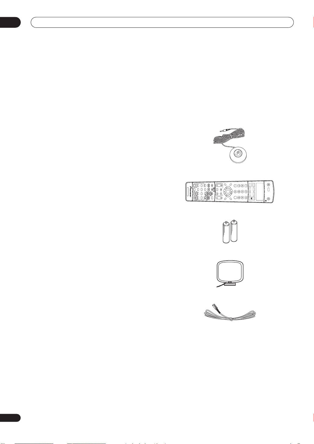
Checking what’s in the box
Please check that you've received the following supplied
accessories:
• Setup microphone
• Remote control unit
GUIDE
TOP MENU
D.ACCESS
RECEIVER
AUTO SURR
AUDIO
SHIFT
MPX
THX
RECEIVER CONTROL
CH RETURN
STANDARD ADV.SURR STEREO
ACOUSTIC
SUBTITLE
/CH SEL
EFFECT
EQ
SIGNAL
SELECT
SLEEP DIALOG E
CH
HDD
MIDNIGHT/
LOUDNESS
CH
DVD
T.EDIT
DISPLAY
TUNER
TV VOL
SYSTEM
SETUP
A
BCDE
REC STOP
ST ST
SELECT
INPUT
TV CONTROL
TUNE
TUNE
REC MUTE
ENTER
TV CH
VOL
RETURN
CLASS
BAND
MENU
• AA/LR6 dry cell batteries x2
• AM loop antenna
• FM wire antenna
• These operating instructions
INPUT ATT FL DIMMER SR
CD
+
CD-R/TAPE
10
MULTI CONTROL
TUNER RECEIVER
ENTER
DISC
RECEIVER
DVD/LD TV/SAT DVR/VCR TV CONT
SELECT
INPUT
SOURCE
6
En
Before you start
01
Installing the
• When installing this unit, make sure to put it on a
level and stable surface.
Don’t install it on the following places:
– on a color TV (the screen may distort)
– near a cassette deck (or close to a device that gives off
a magnetic field). This may interfere with the sound.
– in direct sunlight
– in damp or wet areas
– in extremely hot or cold areas
– in places where there is vibration or other movement
– in places that are very dusty
– in places that have hot fumes or oils (such as a kitchen)
receiver
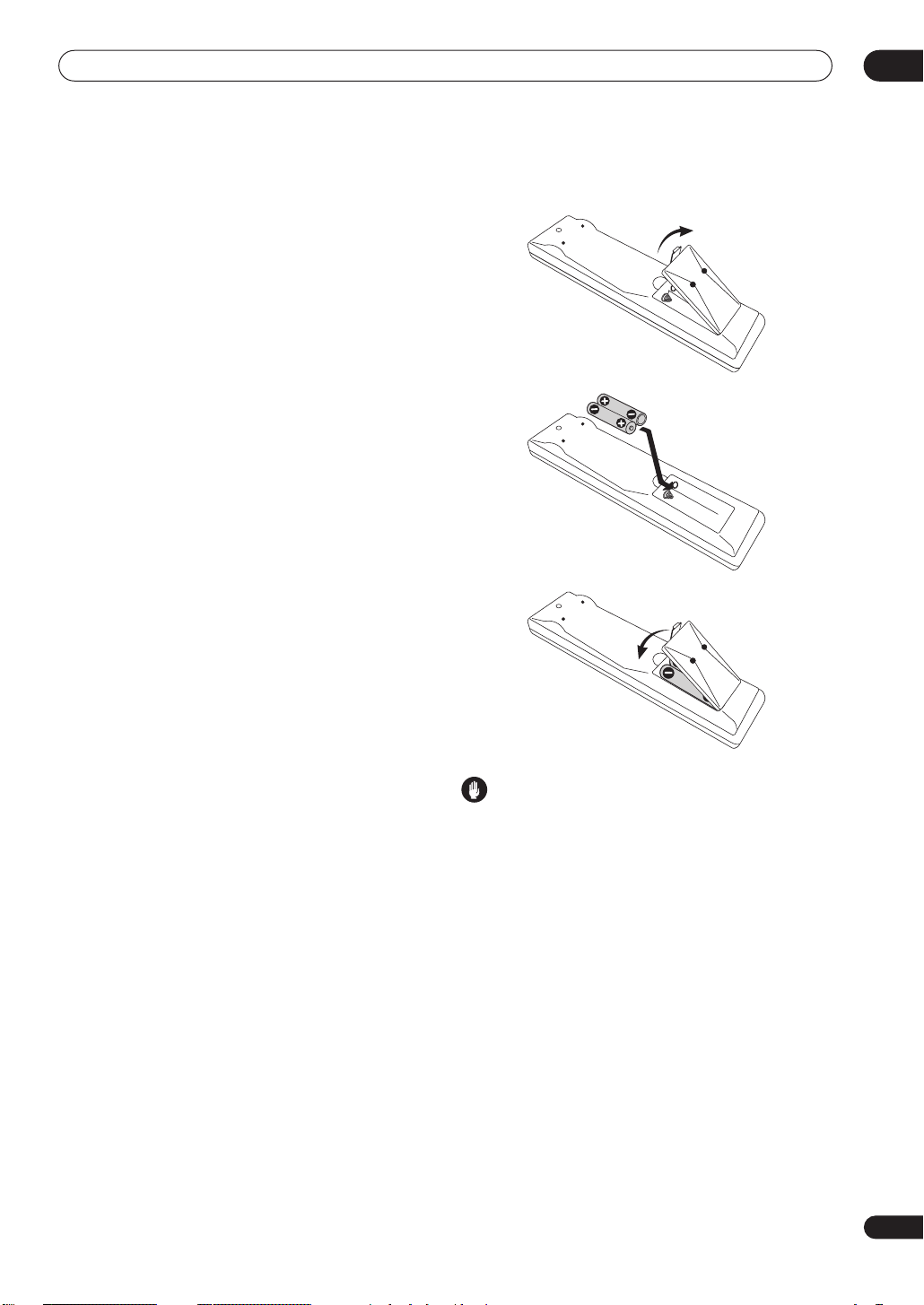
Loading the batteries
Caution
Incorrect use of batteries may result in such hazards as
leakage and bursting. Observe the following precautions:
• Never use new and old batteries together.
• Insert the plus and minus sides of the batteries
properly according to the marks in the battery case.
• Batteries with the same shape may have different
voltages. Do not use different batteries together.
• When disposing of used batteries, please comply
with governmental regulations or environmental
public instruction’s rules that apply in your country or
area.
7
En
02
SURROUND
FRONT
VCR
TV/
SAT
DVD/
LD
IN
VIDEO
VIDEO S-VIDEO
IN
OUT
L
L
CEN-
TER
SUR-
ROUND
FRONT
MONITOR
VIDEO1
IN
OUT
IN
(
DVD/
LD
)
IN
(CD)
IN
OUT
DVD/
LD
TV/
SAT
5
4
REC
(
TV/
SAT
)
IN
2
(DVR/
VCD)
IN
1
(CD-R/
TAPE/
MD)
IN
3
5 minute guide
Chapter 2:
5 minute guide
Introduction to home theater
You are probably used to using stereo equipment to listen to music, but may not be used to home theater systems that
give you many more options (such as surround sound) when listening to soundtracks.
Home theater refers to the use of multiple audio tracks to create a surround sound effect, making you feel like you're
in the middle of the action or concert. The surround sound you get from a home theater system depends not only on
the speakers you have set up in your room, but also on the source and the sound settings of the receiver.
DVD-Video has become the basic source material for home theater due to its size, quality, and ease of use. Depending
on the DVD, you can have up to seven different audio tracks coming from one disc, all of them being sent to different
speakers in your system. This is what creates a surround sound effect and gives you the feeling of ‘being there’.
This receiver will automatically decode Dolby Digital, DTS, or Dolby Surround DVD-Video discs, according to your
speaker setup. In most cases, you won’t have to make changes for realistic surround sound, but other possibilities (like
listening to a CD with multichannel surround sound) are explained in
Listening to Surround Sound
This receiver was designed with the easiest possible setup in mind, so with the following quick setup guide, you should
have your system hooked up for surround sound in no time at all. In most cases, you can simply leave the receiver in
the default settings.
Listening to your system
on page 31.
Important
• Before making or changing any connections, switch off the power and disconnect the power cord from the AC outlet.
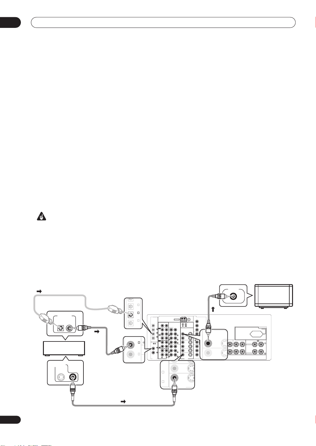
1 Hook up your DVD player.
For surround sound, you’ll want to hook up using a digital connection from the DVD player to the receiver. You can do
this with either a coaxial (recommended), or an optical connection (you don’t need to connect both). If you hook up
using an optical cable, you should refer to
The Input Assign menu
on page 64 to assign the optical input to
DVD
.
Use a video cord to connect the video output on your DVD player to the receiver using the jacks shown below.
2 Hook up your TV.
Use a video cord to connect your receiver to the TV using the jacks as shown below.
Optical cable
DIGITAL OUT
DVD player
VIDEO OUT
S
Coaxial
cable
ASSIGNABLE
Video
cord
AM LOOP
FM UNBAL 75Ω
OUT
(
DVR/
VCR
(
TV/
SAT
(
CD-R/
TAPE/
MD
15
〜
(
DVD/
LD
(CD)
DIGITAL
ANTENNA
CD
PRE OUT
IN
SUBW.
PLAY
1
IN
IN
)
CD-R/
TAPE/MD
2
IN
OUT
)
REC
R L
3
IN
VIDEO1
IN
)
R L
PLAY
IN
DVR /
R
VCR
OUT
REC
4
IN
SUBW.
)
TV/
SAT
IN
RLL
5
IN
DVD/
LD
IN
R L
R L
MULTI CH IN
CEN TER
FRONT
SURROUND
SURROUND
BACK
(
Single
CEN TER
FRONT
SURROUND
)
VIDEO S-VIDEO
Y
CONTROL
P
MONITOR OUT
B
OUT
IN
P
R
MONITOR
OUT
Y
Y
(
(
TV/
DVD
)
)
SAT
/LD
VIDEO1
P
B
P
B
IN
1
IN2IN
P
R
P
R
IN
DVR /
VCR
OUT
Y
TV/
SAT
(
DVR/
P
B
IN
)
VCD
3
IN
DVD/
ASSIGNABLE
P
R
LD
1 3
IN
COMPONENT
VIDEO
VIDEOAUDIO
VIDEO IN
SPEAKERS
FRONT CENTER SURROUND
A B
RL RL
SURROUND BACK /
SELECTABLE
SELECTABLE
AC OUTLET
SWITCHED 100W MAX
(
)
Single
RL
TV
8
En
Video cord
5 minute guide
CD
IN
IN
IN
IN
OUT
CD-R/
TAPE/MD
VIDEO1
DVR /
VCR
PLAY
PLAY
REC
PRE OUT
CEN TER
SUR-
ROUND
SURROUND
BACK
(
Single
)
FRONT
SUBW.
R L
R L
R
L
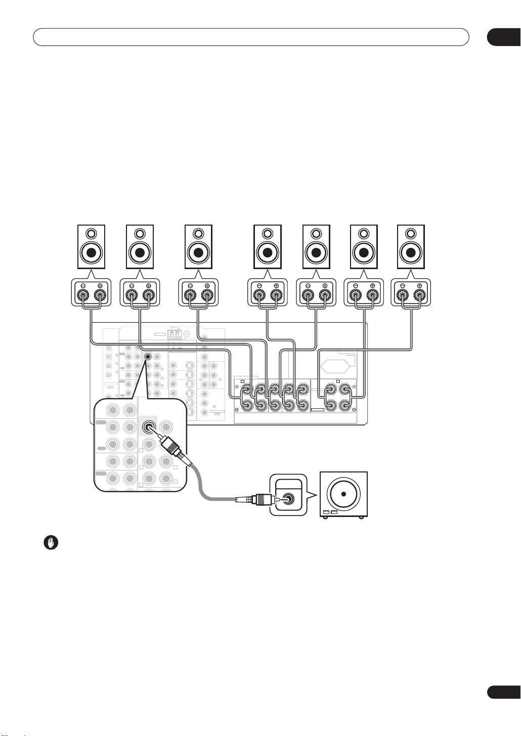
3 Connect your speakers.
A complete setup of eight speakers (including the subwoofer) is shown here but everyone’s home setup will vary.
Simply connect the speakers you have in the manner shown below. The receiver will work with just two stereo speakers
(the front speakers in the diagram) but using at least three speakers is recommended, and a complete setup is best.
Make sure you connect the speaker on the right to the right terminal and the speaker on the left to the left terminal.
Also make sure the positive and negative (
speakers with a nominal impedance between 6–16
plan to use speakers with an impedance of less than 8
• If you only have one surround back speaker, hook it up to the surround back left (
+/–
) terminals on the receiver match those on the speakers. You can use
Ω
(please see
Ω
).
Switching the speaker impedance
Single
) terminal.
on page 73 if you
02
Front speakers
Center speaker
Surround speakers
Surround back speakers
LR C LSRS
AM LOOP
FM UNBAL 75Ω
ASSIGNABLE
15
DIGITAL
ANTENNA
OUT
CD
PRE OUT
IN
SUBW.
PLAY
1
IN
IN
(
DVR/
)
VCR
CD-R/
TAPE/MD
2
IN
(
OUT
TV/
)
SAT
REC
3
IN
VIDEO1
(
CD-R/
IN
TAPE/
)
MD
PLAY
IN
〜
DVR /
VCR
OUT
REC
4
IN
(
DVD/
)
TV/
LD
SAT
IN
5
IN
(CD)
DVD/
LD
IN
R L
R L
R L
R
SUBW.
RRLLL
RR LL
MULTI CH IN
CEN TER
FRONT
SURROUND
SURROUND
BACK
(
)
Single
CEN TER
FRONT
SUR-
ROUND
OUT
IN
MONITOR
OUT
VIDEO1
IN
IN
DVR /
VCR
OUT
TV/
TV/
SAT
SAT
ININ
DVD/LDDVD/
LD
ININ
VIDEOVIDEO S-VIDEOS-VIDEO
VIDEOVIDEOAUDIO
CONTROL
Y
P
MONITOR OUT
B
P
R
YY
YY
(
(
(
(
DVD
DVD
TV/
TV/
)
)
)
)
/LD
/LD
SAT
SAT
PBP
B
PBP
B
11
ININ
PRP
R
Y
P
B
P
R
COMPONENT
VIDEO
(
DVR/
)
VCD
3
IN
ASSIGNABLE
1 3
SPEAKERS
2
ININ
PRP
R
FRONT CENTER SURROUND
A B
RL RL
SWITCHED 100W MAX
SURROUND BACK /
R
SELECTABLE
SELECTABLE
AC OUTLET
L
Powered
subwoofer
SW
INPUT
SBL SBR
(
)
Single
Caution
• These speaker terminals carry
HAZARDOUS LIVE
voltage. To prevent the risk of electric shock when
connecting or disconnecting the speaker cables,
disconnect the power cord before touching any
uninsulated parts.
• Make sure that all the bare speaker wire is twisted
together and inserted fully into the speaker terminal.
Use good quality speaker wire to connect the
speakers to the receiver.
9
En
02
5 minute guide
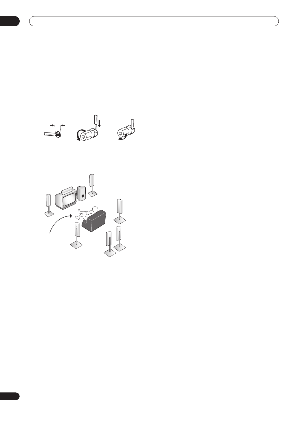
Make sure that the speaker cable you’re going to use is
properly prepared with about 10 mm of insulator stripped
from each wire, and the exposed wire strands twisted
together (
fig. A
).
To connect a terminal, unscrew the terminal a few turns
until there is enough space to insert the exposed wire
(
fig. B
). Once the wire is in position, tighten the terminal
until the wire is firmly clamped (
fig. A fig. B fig. C
10mm
fig. C
).
Where you place the speakers will have a big effect on the
sound. Place your speakers as shown below for the best
surround sound effect. See
Hints on speaker placement
on page 21 for more on this.
Front
speaker
(R)
Surround
speaker (RS)
Front
speaker
(L)
Center
speaker
(C)
Subwoofer (SW)
In addition to the basic playback explained in
source
on page 13, there are several other sound options
you can select. See
for more on this. See also
the System Setup menu
Listening to your system
Making receiver settings from
on page 40 for more setup
options.
• If you’re not familiar with the proper DVD settings,
refer to
Checking the settings on your DVD (or other)
player
on page 13.
Playing a
on page 31
Surround
Listening
position
Surround
speaker (LS)
Surround back
speaker (SBL)
back
speaker (SBR)
4 Plug in the receiver and switch it on, followed by
your DVD player, your subwoofer and the TV.
Make sure you’ve set the video input on your TV to this
receiver. Check the manual that came with the TV if you
don’t know how to do this.
5 Use the on-screen automatic MCACC setup to set
up your system.
See
Automatically setting up for surround sound
(MCACC)
on the next page for more on this.
6 Play a DVD, and adjust the volume to your liking.
Make sure that
DVD/LD
is showing in the receiver’s
display, indicating that the DVD input is selected. If it
isn’t, press
DVD/LD
on the remote control to set the
receiver to the DVD input.
10
En
5 minute guide
02
Automatically setting up for
surround sound (MCACC)
The Auto MCACC Setup measures the acoustic
characteristics of your listening area, taking into account
ambient noise, speaker size and distance, and tests for
both channel delay and channel level. After you have set
up the microphone provided with your system, the
receiver uses the information from a series of test tones
to optimize the speaker settings and equalization for your
particular room.
Make sure you do this before moving on to
source
on page 13.
Important
• Make sure the microphone and speakers are not
moved during the Auto MCACC Setup.
• Using the Auto MCACC Setup will overwrite any
existing speaker settings in the receiver.
• Before using the Auto MCACC Setup the
headphones should be disconnected and
IN
switched off.
• The receiver will automatically exit the current screen
after three minutes of inactivity.
Caution
• The test tones used in the Auto MCACC Setup are
output at high volume.
INPUT
RECEIVER
SELECT
SOURCE
Playing a
MULTI CH
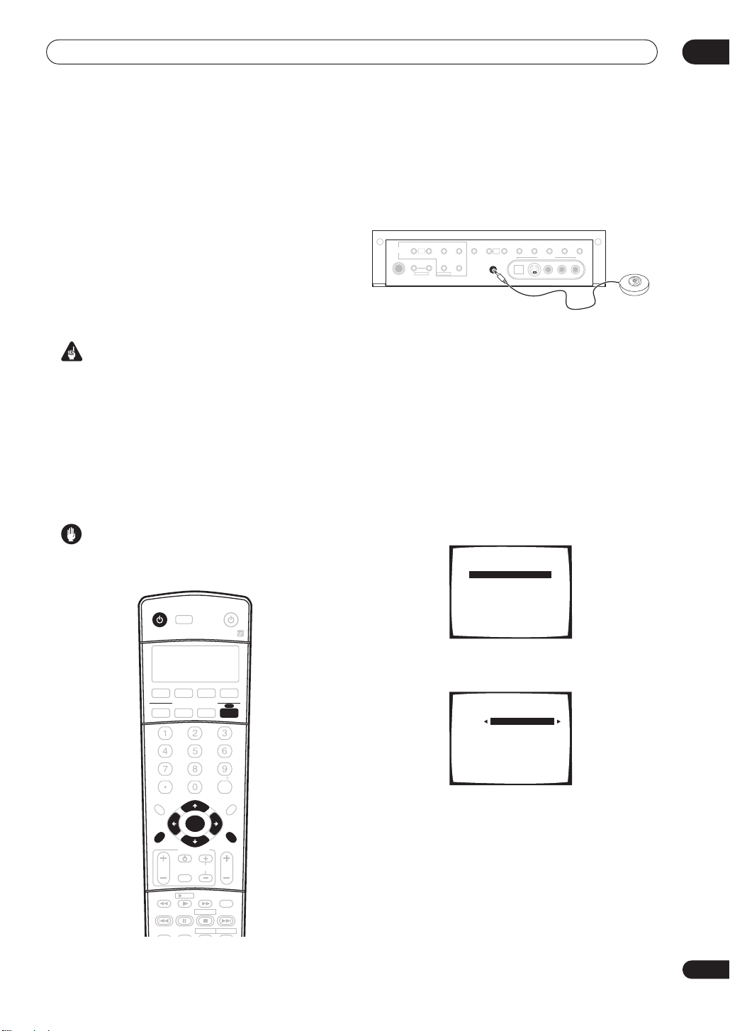
1 Switch on the receiver and your TV.
2 Connect the microphone to the MCACC SETUP
MIC jack on the front panel.
Make sure there are no obstacles between the speakers
and the microphone.
CONTROL
PHONES
TUNER
TUNER
TUNING/
EDIT
STATION
MULTI
JOG
SYSTEM
RETURN
SETUP
MULTI JOG MULTI JOG
MIDNIGHT/
BAND MPX TONE
LOUDNESS
PTY
EON
SEARCH
SETUP MIC
MCACC
ACOUSTIC
EQ
MULTI
JOG
MULTI CHINSIGNAL
DIALOG
ENHANCEMENT
DIGITAL IN S-VIDEO VIDEO
VIDEO2 INPUT
EXTENDED
SPEAKERS
SELECT
MODE
AUDIOLR
If you have a tripod, use it to place the microphone so that
it’s about ear level at your normal listening position.
Otherwise, place the microphone at ear level using a
table or a chair.
3 Press RECEIVER on the remote control, then press
the SYSTEM SETUP button.
An on-screen display (OSD) appears on your TV. Use the
///
buttons and
ENTER
on the remote control to
navigate through the screens and select menu items.
Press
RETURN
• Press
to exit the current menu.
SYSTEM SETUP
at any time to exit the System
Setup menu.
4 Select ‘AUTO MCACC’ from the System Setup
menu then press ENTER.
System Setup
[ 1. Surr Back System ]
[ 2. AUTO MCACC ]
[ 3. MANUAL MCACC ]
[ 4. Manual SP Setup ]
[ 5. Input Assign ]
[ 6. Other Setup ]
Enter : Select
Return : Exit
DVD/LD T V/SAT DVR/VCR TV CONT
MULTI CONTROL
CD-R/TAPE
TUNER RECEIVER
CD
INPUT ATT FL DIMMER SR
+
10
D.ACCESS
TOP MENU
TUNE
ST ST
ENTER
T.EDIT
TUNE
SYSTEM
SETUP
GUIDE
TV CONTROL
INPUT
TV CH
TV VOL
SELECT
REC MUTE
A
TUNER
REC STOP
DISPLAY
BCD E
MPX
CH RETURN
SUBTITLE
HDD
AUDIO
ENTER
CLASS
MENU
BAND
RETURN
VOL
DVD
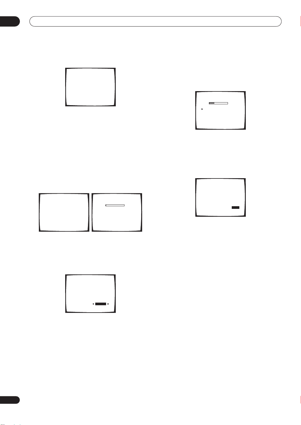
5 Make sure ‘Normal (SB)’ is selected then press
ENTER.
2. AUTO MCACC
Surround Back Output
[ Normal (SB) ]
Enter : Start
DISC
Return : Cancel
• If you are planning on bi-amping your front speakers,
or setting up a separate speaker system in another
room, read through
Surround back speaker setting
on
page 40 and make sure to connect your speakers as
necessary before continuing to step 6.
11
En
02
5 minute guide
6 Follow the instructions on-screen.
2. AUTO MCACC
• Set microphone
• Turn on Sub Woofer
Return : Cancel
• Make sure the microphone is connected.
• If you’re using a subwoofer, it is automatically
detected every time you switch on the system. Make
sure it is on and the volume is turned up.
• See below for notes regarding high background
noise levels and other possible interference.
7 Wait for the Auto MCACC Setup to finish
outputting test tones.
A progress report is displayed on-screen while the
receiver outputs test tones to determine the speakers
present in your setup. Try to be as quiet as possible while
it’s doing this.
2. AUTO MCACC
Please wait
Caution!!
Test tone is
output loudly.
Return:Cancel
2. AUTO MCACC
Now Analyzing
Environment Check
Ambient Noise [ ]
Microphone [ ]
Speaker YES/NO [ ]
•••
Return:Cancel
• Do not adjust the volume during the test tones. This
may result in incorrect speaker settings.
8 Confirm the speaker configuration in the OSD.
The configuration shown on-screen should reflect the
actual speakers you have.
2. AUTO MCACC
Check!!!
Front [ YES ]
Center [ YES ]
Surround [ YES ]
Surr Back [ YES
Sub Woofer [ YES ]
[ OK ]
X
2]
If the speaker configuration displayed isn’t correct, use
the
/
and
(cursor up/down) buttons to select the speaker
/
(cursor left/right) to change the setting (and
number for surround back). When you’re finished, go to
the next step.
If you see an error message (
ERR
) in the right side
column, there may be a problem with the speaker
connection. If selecting
RETRY
doesn’t fix the problem,
turn off the power and check the speaker connections.
9 Make sure ‘OK’ is selected, then press ENTER.
A progress report is displayed on-screen while the
receiver outputs more test tones to determine the
optimum receiver settings for channel level, speaker
distance, and Acoustic Calibration EQ.
2. AUTO MCACC
Now Analyzing
Surround Analyzing
Speaker System [ ]
Speaker Distance [ ]
Channel Level [ ]
Acoustic Cal EQ [ ]
•••
Return:Cancel
Again, try to be as quiet as possible while this is
happening. It may take 3–8 minutes.
10 The Auto MCACC Setup has finished! Select
‘Skip’ to go back to the System Setup menu.
The MCACC indicator on the front panel will light to show
the surround settings are complete.
2. AUTO MCACC
Analyzed Data Check
[a.Speaker Setting ]
[b.Speaker Distance ]
[c.Channel Level ]
[d.Acoustic Cal EQ ]
[ Skip ]
The settings made in the Auto MCACC Setup should give
you excellent surround sound from your system, but it is
also possible to adjust these settings manually using the
System Setup menu (see page 40).
• If you are using THX Certified speakers, confirm that
all speakers are set to
page 46, and that the
is set to
80Hz
.
SMALL
in
Speaker Setting
Crossover Network
on
on page 47
You can also choose to view the settings by selecting
individual parameters from the
Analyzed Data Check
screen:
•
Speaker Setting
– The size and number of speakers
you’ve connected (see page 46 for more on this)
•
Speaker Distance
– The distance of your speakers
from the listening position (see page 48 for more on
this)
•
Channel Level
– The overall balance of your speaker
system (see page 47 for more on this)
•
Acoustic Cal EQ
– Adjustments to the frequency
balance of your speaker system based on the
acoustic characteristics of your room (see page 43
for more on this)
Press
RETURN
screen. When you’re finished, select
after you have finished checking each
Skip
to go back to
the System Setup menu.
12
En

5 minute guide
02
Note
• If you leave an error message on the screen for over
three minutes, or if you cancel the Auto MCACC
Setup at any time, the receiver automatically exits
and no settings will be made.
• Depending on the characteristics of your room,
sometimes identical speakers with cone sizes of
around 12cm will end up with different size settings.
You can correct the setting manually using the
Manual speaker setup
• The subwoofer distance setting may be farther than
the actual distance from the listening position. This
setting should be accurate (taking delay and room
characteristics into account) and generally does not
need to be changed.
• Remember to disconnect the microphone after
you’ve finished the Auto MCACC Setup.
on page 45.
Playing a source
Here are the basic instructions for playing a source (such
as a DVD disc) with your home theater system.
1 Turn on the power of the playback component
(for example a DVD player), your TV and subwoofer
(if you have one).
Other problems when using the Auto MCACC
Setup
If the room environment is not optimal for the Auto
MCACC Setup (too much background noise, echo off the
walls, obstacles blocking the speakers from the
microphone) the final settings may be incorrect. Check
for household appliances (air conditioner, fridge, fan,
etc.), that may be affecting the environment and switch
them off if necessary. If there are any instructions
showing in the front panel display, please follow them.
• Some older TVs may interfere with the operation of
the microphone. If this seems to be happening,
switch off the TV when doing the Auto MCACC Setup.
Checking the settings on your DVD
2 If the receiver isn’t already on, press RECEIVER
to switch it on.
3 Change the receiver input to the source you
want to play.
You can use the front panel input select buttons or the
dedicated
control.
4 Press AUTO SURR (remote control) and start
playback of the DVD (or other component).
If you’re playing a Dolby Digital or DTS surround sound
DVD disc, you should hear surround sound. If you are
playing a stereo source, you will only hear sound from the
front left/right speakers in the default listening mode.
(or other) player
Before continuing, you may want to check the digital
audio output settings on your DVD player and digital
satellite receiver.
• Check that your DVD player/satellite receiver is
set to output Dolby Digital, DTS and 88.2/96kHz PCM
(2 channel) audio.
If there is an option for MPEG audio, set this to convert
the MPEG audio to PCM.
If you connected the multichannel analog outputs of the
player to this receiver, make sure that the player is set to
output multichannel analog audio.
5 Use the volume control (front panel or remote)
to adjust the volume level.
Note
• Depending on your DVD player or source discs, you
may only get digital 2 channel stereo and analog
sound. In this case, the receiver must be set to a
multichannel listening mode (see
surround sound
you want multichannel surround sound.
• If your source is the TV’s built-in tuner, then switch to
the channel you want to watch, otherwise make sure
that the TV’s video input is set to this receiver. (For
example, if you connected this receiver to the
1
jacks on your TV, make sure that the
is now selected.)
MULTI CONTROL
• See also
more information on different ways of listening to
sources.
• Turn down the volume of your TV so that all the sound
is coming from the speakers connected to this
receiver.
• Adjust the volume to your liking between
(min) and
Note
• If you need to manually switch the input signal type
from digital to analog (stereo or multichannel), press
SIGNAL SELECT
• For more detailed surround sound setup, see
System Setup menu
on page 31 if you need to do this) if
buttons on the remote
Listening to your system
+12dB
(max).
(page 35).
on page 40.
Listening in
VIDEO
VIDEO 1
on page 31 for
input
–80dB
The
13
En
03
S
Connecting up
Chapter 3:
Connecting up
Important
• Before making or changing any connections, switch
off the power and disconnect the power cord from the
AC outlet.
About cable types
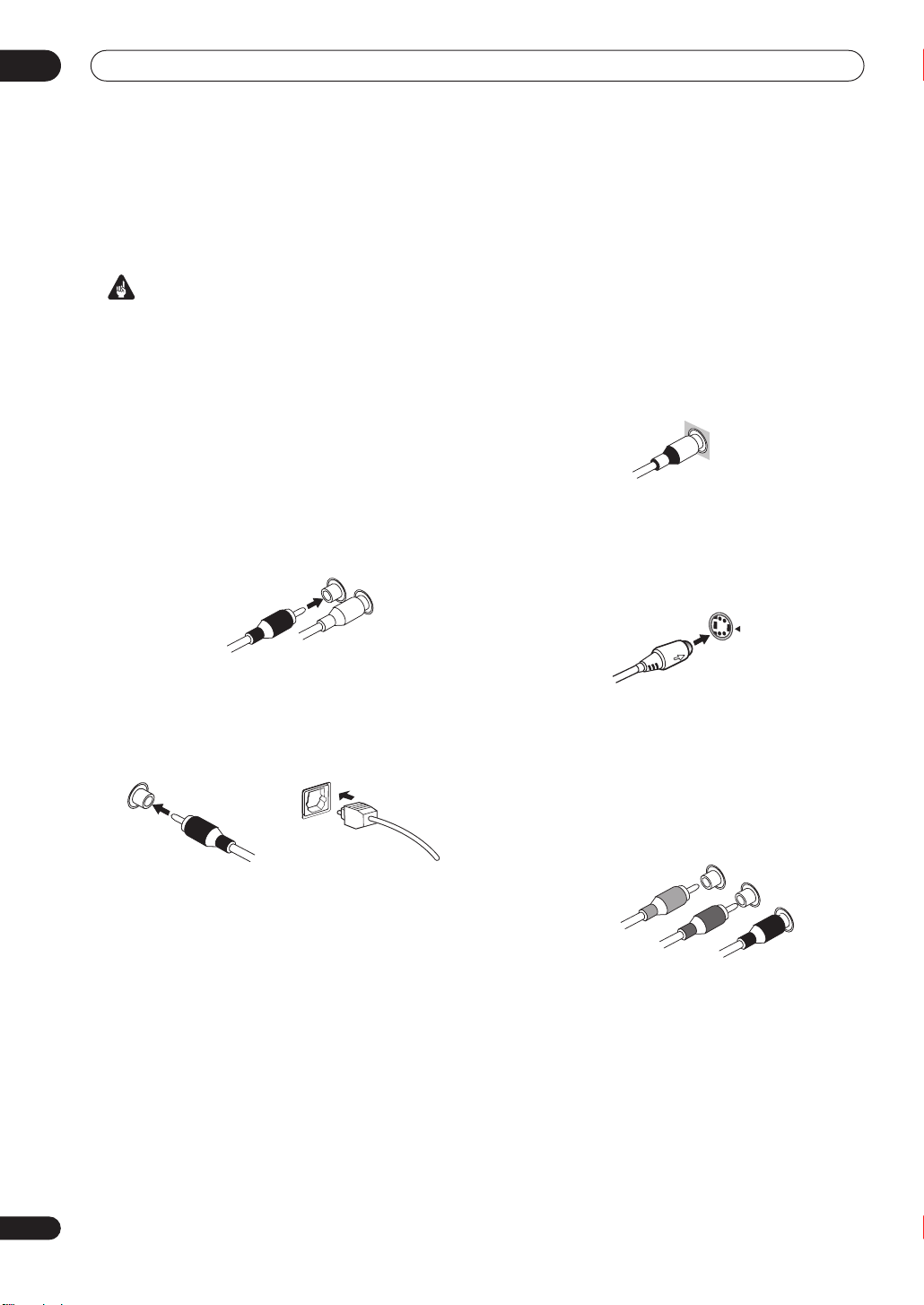
Analog audio cables
Use stereo RCA phono cables to connect analog audio
components. These cables are typically red and white,
and you should connect the red plugs to R (right)
terminals and white plugs to L (left) terminals.
Analog audio cables
Right (red)
Left (white)
Digital audio cables
Commercially available coaxial digital audio cables or
optical cables should be used to connect digital
components to this receiver.
Video cables
Standard RCA video cables
These cables are the most common type of video
connection and should be used to connect to the
composite video terminals. They have yellow plugs to
distinguish them from cables for audio.
tandard RCA video cable
S-video cables
S-video cables give you clearer picture reproduction than
standard RCA video cables by sending separate signals
for the luminance and color.
S Video
Component video cables
Use component video cables to get the best possible
color reproduction of your video source. The color signal
of the TV is divided into the luminance (
color (
PB and
interference between the signals is avoided.
PR) signals and then output. In this way,
Y
) signal and the
Component video cables
Coaxial digital audio cable Optical cable
• When connecting optical cables, be careful when
inserting the plug not to damage the shutter
protecting the optical socket.
• When storing optical cable, coil loosely. The cable
may be damaged if bent around sharp corners.
• You can also use a standard RCA video cable for
coaxial digital connections.
Green (Y)
Blue (P
B)
Red (P
R)
14
En
Connecting up
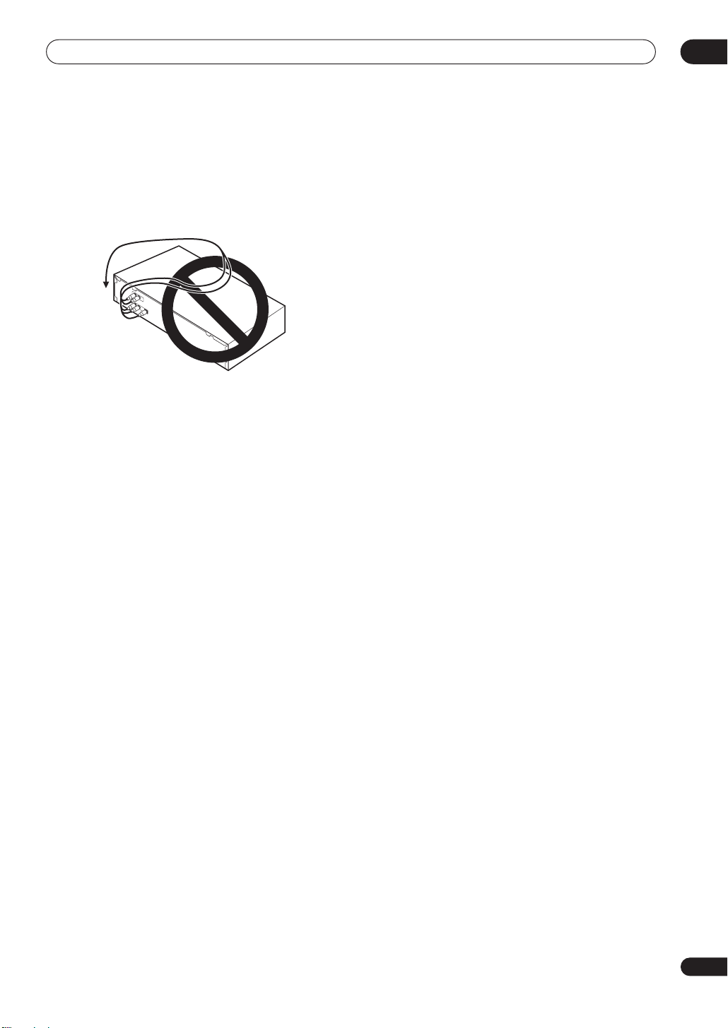
When making cable connections
Be careful not to arrange cables in a manner that bends
the cables over the top or around this unit. If the cables
are laid on top of the unit, the magnetic field produced by
the transformers in this unit may cause a humming noise
to come from the speakers.
03
15
En
03
O
Connecting up
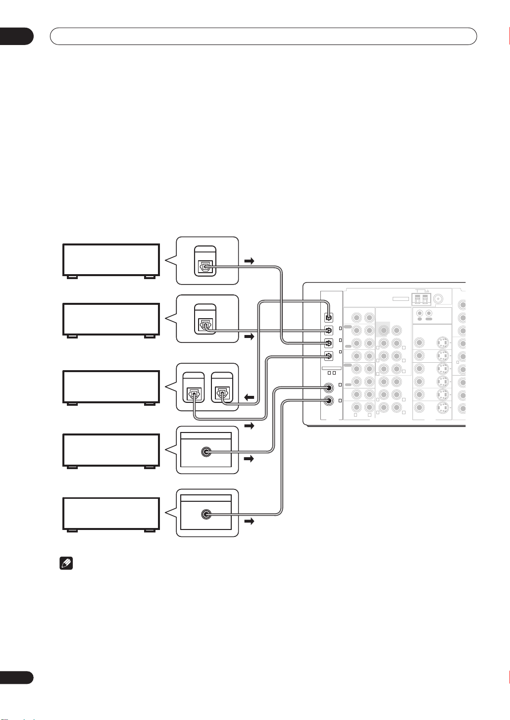
Connecting digital audio components
The easiest way to hook up this receiver for surround sound (Dolby Digital and DTS sources) is to use a digital input.
You can do this by either coaxial or optical connections (you do not need to do both). The quality of these two types of
connections is the same but since some digital components only have one type of digital terminal, it is a matter of
matching like with like (for example, the coaxial output from the component to coaxial input on the receiver). This
receiver has five digital inputs (two coaxial inputs and three optical inputs) on the rear panel. Connect your digital
components as shown below.
There is one digital output jack which is marked
recorder (for example an MD, DAT or CD-R) you can make direct digital recordings with this unit.
When connecting your equipment, always make sure the power is turned off and the power cord is disconnected from
the AC outlet.
• The arrows indicate the direction of the signal.
DIGITAL OUT
. If you connect this to the optical input on a digital
Satellite tuner
DVR or VCR
CD recorder
DVD or LD player
CD player
DIGITAL
OUT
DIGITAL
OUT
DIGITAL
OUT
DIGITAL OUT
COAX
DIGITAL OUT
COAX
DIGITAL
IN
ASSIGNABLE
15
〜
DIGITAL
OUT
(
DVR/
VCR
(
TV/
SAT
(
CD-R/
TAPE/
MD
(DVD/
LD)
(CD)
AM LOOP
L
)
Single
LL
FM UNBAL 75Ω
CONTROL
OUT
IN
MONITOR
OUT
VIDEO1
IN
IN
DVR /
VCR
OUT
TV/
TV/
SAT
SAT
ININ
DVD/LDDVD/
LD
ININ
VIDEOVIDEO S-VIDEOS-VIDEO
VIDEOVIDEOAUDIO
Y
P
B
P
R
YY
(
(
DVD
DVD
)
)
/LD
/LD
PBP
B
11
ININ
PRP
R
Y
P
B
P
R
C
ANTENNA
CD
IN
PLAY
1
IN
IN
)
CD-R/
TAPE/MD
2
IN
OUT
)
REC
3
IN
VIDEO1
IN
)
PLAY
IN
DVR /
VCR
OUT
REC
4
IN
TV/
SAT
IN
5
IN
DVD/
LD
IN
R L
PRE OUT
SUBW.
R L
R L
R
SUBW.
RR
RR LL
MULTI CH IN
CEN TER
FRONT
SURROUND
SURROUND
BACK
(
CEN TER
FRONT
SURROUND
16
En
Note
• If your digital connections are different from the default settings, you should refer to
page 64 to assign the jacks to the proper component(s).
• If you have a have a DVD-Audio or SACD compatible player, see
Connecting multichannel analog components
page 17.
The Input Assign menu
on
on
Connecting up
E
A
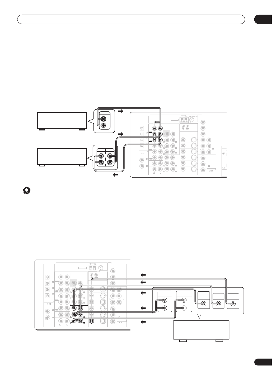
Connecting analog audio components
To begin set up, connect your analog audio components (such as a cassette deck) to the jacks. For components you
want to record with, you need to hook up four plugs to the receiver (a set of stereo inputs and a set of stereo outputs),
but for components that only play, you only need to hook up one set of stereo plugs. You must also hook up your digital
components to analog audio jacks if you want to record to/from digital components (like an MD) to/from analog
components. See page 16 for more on digital connections.
When connecting your equipment, always make sure the power is turned off and the power cord is disconnected from
the AC outlet.
• The arrows indicate the direction of the audio signal.
03
CD player
CD-R/Tape/MD deck
OUTPUT
REC
L
R
L
R
PLAY
ASSIGNABLE
15
DIGITAL
OUT
CD
IN
PLAY
1
IN
IN
(
DVR/
)
VCR
CD-R/
TAPE/MD
2
IN
(
OUT
TV/
)
SAT
REC
3
IN
VIDEO1
(
CD-R/
IN
TAPE/
)
MD
PLAY
IN
DVR /
VCR
OUT
REC
4
IN
(DVD/
TV/
LD)
SAT
IN
5
IN
(CD)
DVD/
LD
IN
RL
ANTENNA
PRE OUT
SUBW.
R L
R L
R
SUBW.
RR
RR LL
MULTI CH IN
AM LOOP
CEN TER
FRONT
SURROUND
SURROUND
BACK
L
(
Single
CEN TER
FRONT
LL
SURROUND
)
CONTROL
OUT
IN
MONITOR
OUT
VIDEO1
IN
IN
DVR /
VCR
OUT
TV/
TV/
SAT
SAT
ININ
DVD/LDDVD/
LD
ININ
VIDEOVIDEO S-VIDEOS-VIDEO
VIDEOVIDEOAUDIO
(
(
/LD
/LD
ININ
Y
P
P
YY
DVD
DVD
PBP
PRP
Y
P
P
B
R
)
)
B
11
R
B
R
MONITOR OUT
COMPONENT
VIDEO
(
(
TV/
TV/
SAT
SAT
ININ
(
DVR/
)
VCD
3
IN
ASSIGNABLE
1 3
YY
)
)
PBP
B
SP
2
PRP
R
Tip
• If you don’t plan on using the spare audio jacks for video components (for example,
VIDEO1
), you can use these
for connecting another audio component, like a line-level turntable.
Connecting multichannel analog components
If you prefer to use a separate component for decoding multichannel formats such as DVD Audio and SACD, you can
connect a decoder or a DVD player with multichannel analog outputs to the multichannel inputs of this receiver. Note
that the multichannel input can only be used when
When connecting your equipment, always make sure the power is turned off and the power cord is disconnected from
the AC outlet.
• The arrows indicate the direction of the signal.
AM LOOP
CEN TER
FRONT
SURROUND
SURROUND
BACK
(
CEN TER
FRONT
L
)
Single
SURROUND
FM UNBAL 75Ω
CONTROL
OUT
IN
MONITOR
OUT
VIDEO1
IN
IN
DVR /
VCR
OUT
TV/
TV/
SAT
SAT
ININ
DVD/LDDVD/
LD
ININ
VIDEOVIDEO S -VIDEOS-VIDEO
VIDEOVIDEO
ASSIGNABLE
15
〜
DIGITAL
OUT
(
VCR
(
TV/
SAT
(
CD-R/
TAPE/
MD
(DVD/
LD)
(CD)
ANTENNA
CD
IN
PLAY
1
IN
IN
DVR/
)
CD-R/
TAPE/MD
2
IN
OUT
)
REC
3
IN
VIDEO1
IN
)
PLAY
IN
DVR /
VCR
OUT
REC
4
IN
TV/
SAT
IN
5
IN
DVD/
LD
IN
R L
PRE OUT
SUBW.
R L
R L
R
SUBW.
R L
R L
MULTI CH IN
AUDIO
MULTI CH IN
Y
P
MONITOR OUT
B
P
R
YY
(
(
DVD
DVD
)
)
/LD
/LD
PBP
B
11
ININ
PRP
R
Y
(
DVR/
P
B
VCD
3
IN
ASSIGNABLE
P
R
COMPONENT
VIDEO
is selected (see page 39).
YY
(
(
TV/
TV/
)
)
SAT
SAT
PBP
B
2
ININ
PRP
R
)
1 3
FRONT
OUTPUT
L
R
SURROUND
OUTPUT
SUB
WOOFER
OUTPUT
L
R
DVD/multi-channel decoder
CENTER
OUTPUT
VIDEO
OUTPUT
with multi-channel analog
output jacks
17
En
03
Connecting up
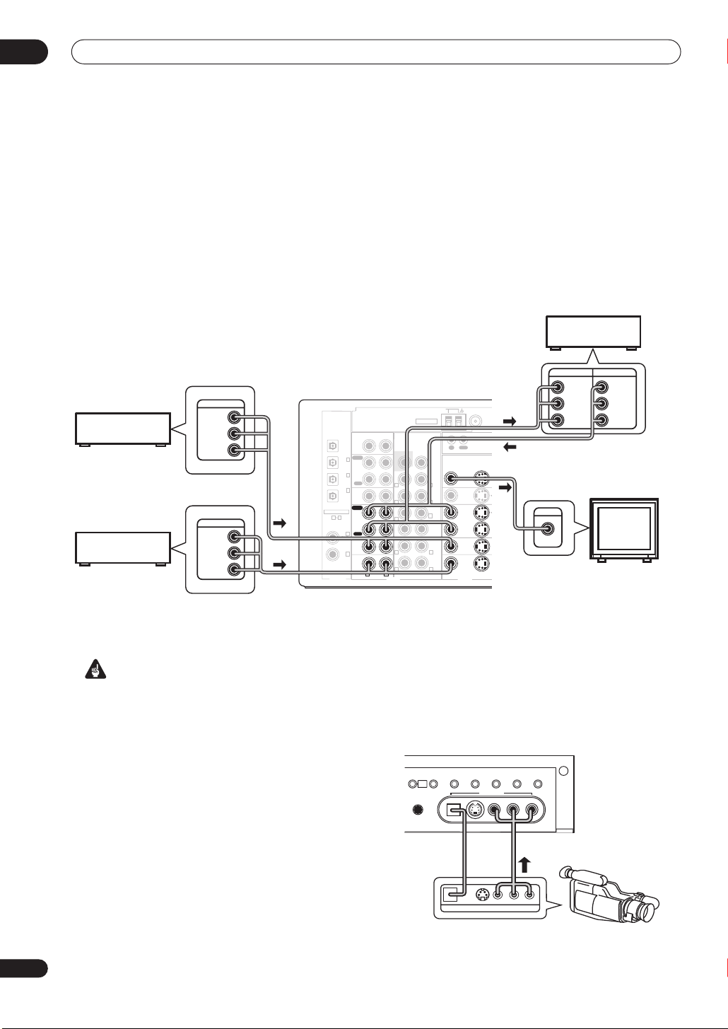
Connecting video components
Connect your video components to the jacks as shown below. With digital video components (like a DVD player), you
must use the connections shown on this page for the video signal, but in order to hear a digital source (like a DVD)
you should hook up the audio to a digital input (see page 16). It is also a good idea to hook up your digital components
with analog audio connections (see page 17).
For better quality video, you can hook up using the component video jacks or the S-video jacks (quality descends in
this order) on the rear of the receiver instead of the regular video jacks.
When connecting your equipment, always make sure the power is turned off and the power cord is disconnected from
the AC outlet.
• The arrows indicate the direction of the signal.
Video deck
INPUT
OUTPUT
TV tuner
(or Satellite tuner)
DVD or LD player
OUTPUT
VIDEO
OUTPUT
VIDEO
VIDEO
AM LOOP
CEN TER
FRONT
SURROUND
SURROUND
BACK
(
CEN TER
FRONT
L
)
Single
SURROUND
FM UNBAL 75Ω
CONTROL
OUT
IN
MONITOR
OUT
VIDEO1
IN
IN
DVR /
VCR
OUT
TV/
TV/
SAT
SAT
ININ
DVD/LDDVD/
LD
ININ
VIDEOVIDEO S -VIDEOS-VIDEO
VIDEOVIDEO
(
(
/LD
/LD
Y
P
B
P
R
YY
DVD
DVD
PBP
B
ININ
PRP
R
Y
P
B
P
R
)
)
11
MONITOR OUT
(
DVR/
VCD
IN
ASSIGNABLE
COMPONENT
VIDEO
ANTENNA
L
R
L
R
ASSIGNABLE
15
DIGITAL
(
VCR
(
SAT
(
CD-R/
TAPE/
MD
OUT
CD
IN
PLAY
1
IN
IN
DVR/
)
CD-R/
TAPE/MD
2
IN
OUT
TV/
)
REC
3
IN
VIDEO1
IN
)
PLAY
IN
DVR /
VCR
OUT
4
REC
IN
(DVD/
TV/
LD)
SAT
IN
5
IN
(CD)
DVD/
LD
IN
R L
PRE OUT
SUBW.
R L
R L
R
SUBW.
R L
R L
MULTI CH IN
AUDIO
L
R
YY
(
(
TV/
TV/
)
)
SAT
SAT
PBP
B
2
ININ
PRP
R
INPUT
VIDEO
)
3
1 3
VIDEO
L
R
TV (monitor)
18
En
Important
• Make sure to use the same type of cable for your
video connections as you used to connect your TV.
Connecting to the front panel video terminal
Front video connections are accessed via the front panel
using the
video jacks as well as an S-video jack and an optical
input. Hook them up the same way you made the rear
panel connections.
VIDEO2
ACOUSTICEQMULTI CHINSIGNAL
DIALOG
TONE
ENHANCEMENT
MULTI
JOG
MCACC
SETUP MIC
DIGITAL IN S-VIDEO VIDEO
DIGITAL OUT
button. There are standard audio/
EXTENDED
SPEAKERS
SELECT
MODE
VIDEO2 INPUT
AUDIOLR
Video
camera
(etc.)
LV
R
VIDEO OUTPUT
Connecting up
LOOP
03
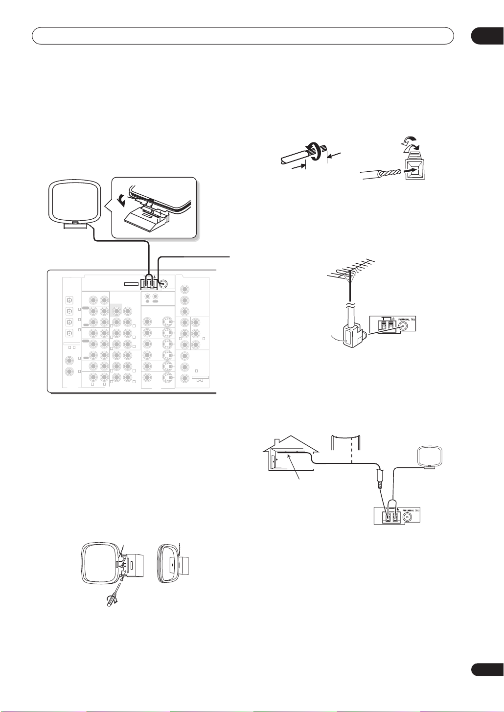
Connecting antennas
Connect the AM loop antenna and the FM wire antenna
as shown below. To improve reception and sound quality,
connect external antennas (see
below). Always make sure that the receiver is switched off
and unplugged from the wall outlet before making or
changing any connections.
AM loop
antenna
OUT
ASSIGNABLE
15
〜
DIGITAL
CD
IN
PLAY
1
IN
IN
(
DVR/
)
VCR
CD-R/
TAPE/MD
2
IN
(
OUT
TV/
)
SAT
REC
3
IN
VIDEO1
(
CD-R/
IN
TAPE/
)
MD
PLAY
IN
DVR /
VCR
OUT
REC
4
IN
(
DVD/
)
TV/
LD
SAT
IN
5
IN
(CD)
DVD/
LD
IN
R L
PRE OUT
SUBW.
R L
R L
R
SUBW.
RR
RR LL
MULTI CH IN
FM wire antenna
Connect the FM wire antenna and fully extend vertically
along a window frame or another suitable place that
gives good reception.
AM loop antenna
Assemble the antenna and connect to the receiver as
shown above. The ground terminal (
radio noise (it is not an earthing plug). Attach (if
necessary) and face in the direction that gives the best
reception.
Using external antennas
FM wire antenna
AM LOOP
CEN TER
FRONT
SURROUND
SURROUND
BACK
L
(
)
Single
CEN TER
FRONT
LL
SURROUND
FM UNBAL 75Ω
CONTROL
OUT
IN
MONITOR
OUT
VIDEO1
IN
IN
DVR /
VCR
OUT
TV/
TV/
SAT
SAT
ININ
DVD/LDDVD/
LD
ININ
VIDEOVIDEO S-VIDEOS-VIDEO
VIDEOVIDEOAUDIO
Y
P
B
P
R
YY
(
(
DVD
DVD
/LD
/LD
PBP
B
11
ININ
PRP
R
Y
P
B
P
R
) helps reduce
ANTENNA
)
)
COMPONENT
MONITOR OUT
(
DVR/
VCD
IN
ASSIGNABLE
VIDEO
YY
(
(
TV/
TV/
)
)
SAT
SAT
PBP
B
2
ININ
PRP
R
)
3
1 3
Antenna snap connectors
Twist the exposed wire strands together and insert into
the hole, then snap the connector shut.
10mm
Using external antennas
To improve FM reception
Use an F connector to connect an external FM antenna
using a coaxial 75
To improve AM reception
Connect a 5–6m length of vinyl-coated wire to the AM
antenna terminal without disconnecting the supplied AM
loop antenna.
For the best possible reception, suspend horizontally
outdoors.
Indoor antenna
(vinyl-coated wire)
Ω
cable.
F connector
LOOP
Outdoor
antenna
5–6m
• Note that either wire can be inserted into the
respective terminals when connecting.
19
En
03
CD
IN
IN
IN
IN
OUT
CD-R/
TAPE/MD
VIDEO1
DVR /
VCR
PLAY
PLAY
REC
PRE OUT
CEN TER
SUR-
ROUND
SURROUND
BACK
(
Single
)
FRONT
SUBW.
R L
R L
R
L
Connecting up
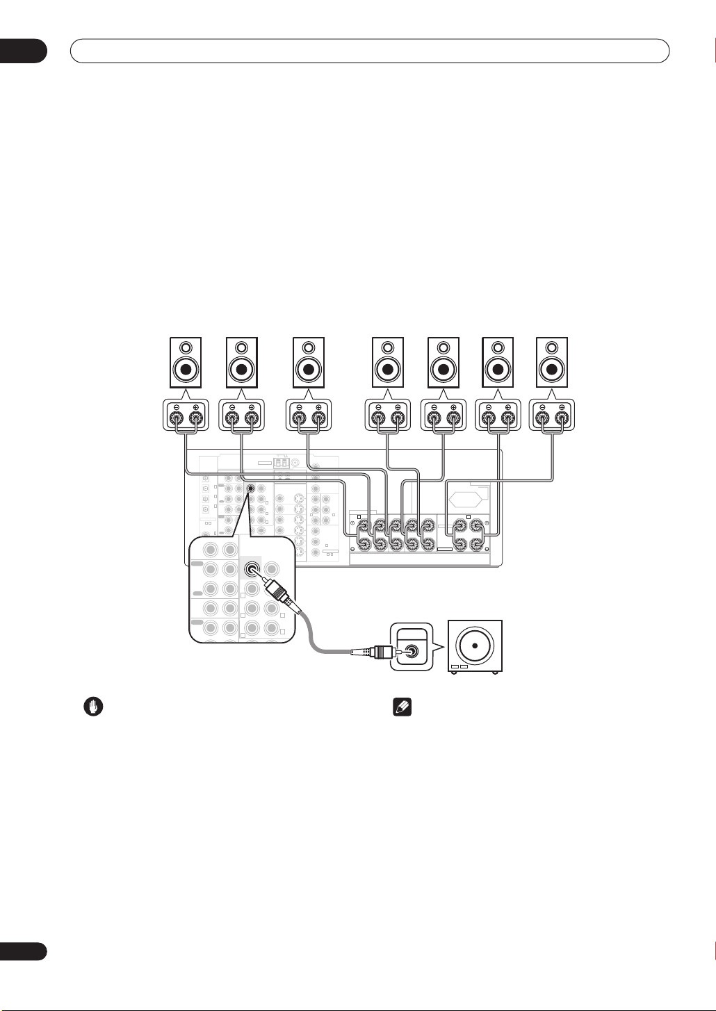
Connecting the speakers
A complete setup of eight speakers (including the subwoofer) is shown below, but everyone’s home setup will vary.
Simply connect the speakers you have in the manner shown below. The receiver will work with just two stereo speakers
(the front speakers in the diagram) but using at least three speakers is recommended, and a complete setup is best
for surround sound. If you’re not using a subwoofer, change the front speaker setting (see
to large.
Make sure you connect the speaker on the right to the right terminal and the speaker on the left to the left terminal.
Also make sure the positive and negative (
• You can use speakers with a nominal impedance between 6–16
page 73 if you plan to use speakers with an impedance of
+/–
) terminals on the receiver match those on the speakers.
Ω
(please see
less than 8Ω
Switching the speaker impedance
).
Be sure to complete all connections before connecting this unit to the AC power source.
Front speakers
Center speaker
LR C LSRS
AM LOOP
FM UNBAL 75Ω
ASSIGNABLE
DIGITAL
OUT
1
IN
(
DVR/
)
VCR
2
IN
(
TV/
)
SAT
3
IN
(
CD-R/
TAPE/
)
MD
15
〜
4
IN
(
DVD/
)
LD
5
IN
(CD)
ANTENNA
CD
PRE OUT
IN
SUBW.
PLAY
IN
CD-R/
TAPE/MD
OUT
REC
VIDEO1
IN
PLAY
IN
DVR /
VCR
OUT
REC
TV/
SAT
IN
DVD/
LD
IN
R L
R L
R L
R
SUBW.
RRLLL
RR LL
MULTI CH IN
CEN TER
FRONT
SURROUND
SURROUND
BACK
(
CEN TER
FRONT
SUR-
ROUND
)
Single
OUT
IN
MONITOR
OUT
VIDEO1
IN
IN
DVR /
VCR
OUT
TV/
TV/
SAT
SAT
ININ
DVD/LDDVD/
LD
ININ
VIDEOVIDEO S-VIDEOS-VIDEO
VIDEOVIDEOAUDIO
CONTROL
Y
P
MONITOR OUT
B
P
R
YY
YY
(
(
(
(
DVD
DVD
TV/
TV/
)
)
/LD
/LD
SAT
SAT
PBP
PBP
B
11
ININ2ININ
PRP
PRP
R
Y
(
DVR/
P
B
)
VCD
3
IN
ASSIGNABLE
P
R
1 3
COMPONENT
VIDEO
Surround speakers
)
)
B
SPEAKERS
FRONT CENTER SURROUND
A B
RL RL
R
Surround back speakers
AC OUTLET
SWITCHED 100W MAX
SURROUND BACK /
SELECTABLE
SELECTABLE
(
Single
L
R
Speaker Setting
SBL SBR
)
on page 46)
on
20
En
Caution
• These speaker terminals carry
HAZARDOUS LIVE
voltage. To prevent the risk of electric shock when
connecting or disconnecting the speaker cables,
disconnect the power cord before touching any
uninsulated parts.
• Make sure no bare speaker wire is touching the back
panel when the unit is switched on. The power may
cut off as a safety measure.
Powered
subwoofer
SW
INPUT
Note
• If you only have one surround back speaker, hook it
up to the surround back left (
Single
) terminal.
• If you are planning on bi-amping your front speakers,
or setting up a separate speaker system in another
room, read through
Surround back speaker setting
on
page 40 and make sure to connect your speakers as
necessary (these connections are explained in
connections
on page 60).
Other
• If you are using a THX certified subwoofer use the
THX INPUT
has one) or switch the filter position to
jack on the subwoofer (if your subwoofer
THX
on your
subwoofer.
Connecting up
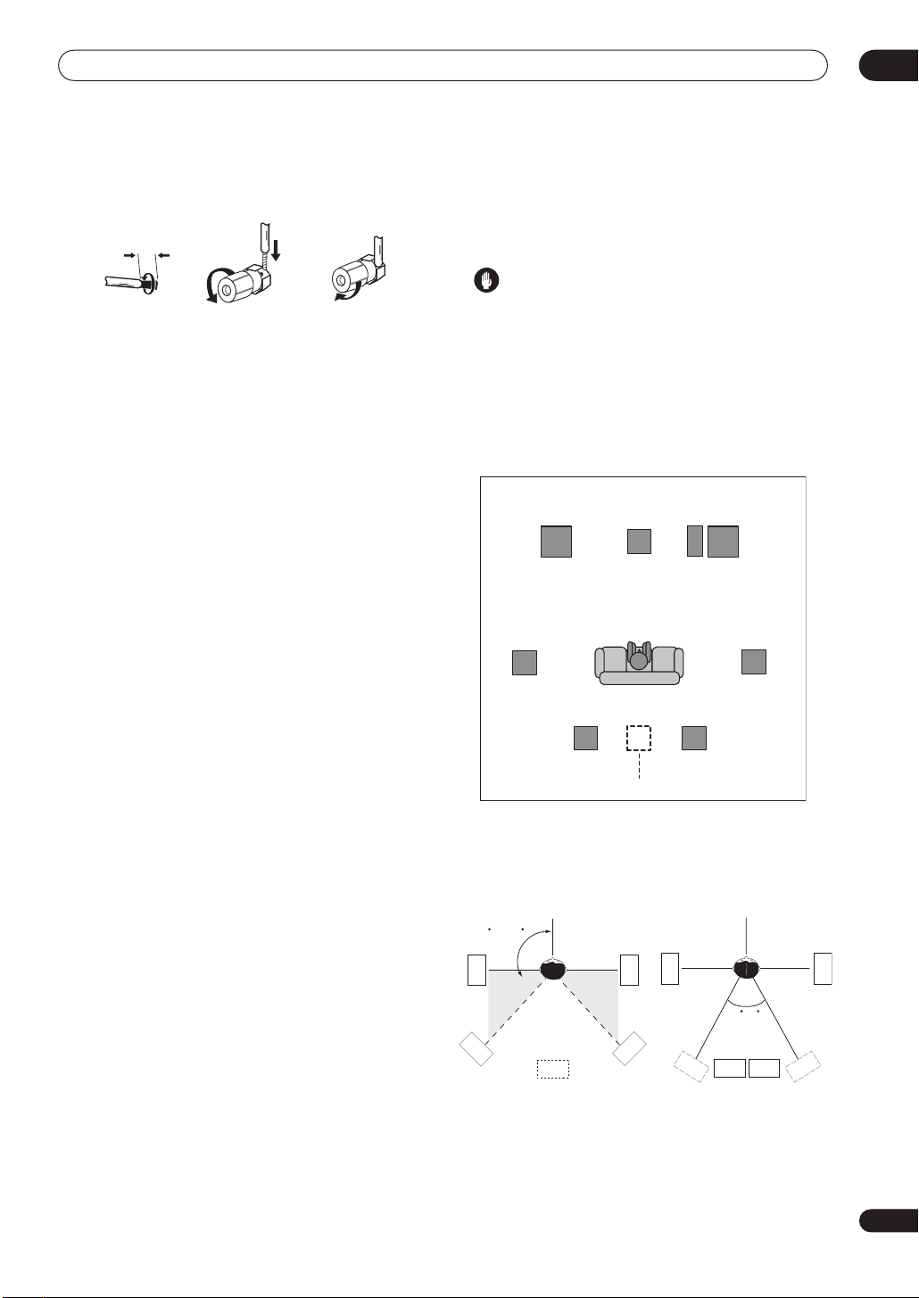
03
Speaker terminals
12 3
10mm
1 Twist exposed wire strands together.
2 Loosen speaker terminal and insert exposed
wire.
Make sure that all the bare speaker wire is twisted
together and inserted fully into the speaker terminal. Use
good quality speaker wire to connect the speakers to the
receiver.
3 Tighten terminal.
Hints on speaker placement
Speakers are usually designed with a particular
placement in mind. Some are designed to be
floorstanding, while others should be placed on stands to
sound their best. Some should be placed near a wall;
others should be placed away from walls. We have
provided a few tips on getting the best sound from your
speakers (following), but you should also follow the
guidelines on placement that the speaker manufacturer
provided with your particular speakers to get the most
out of them.
• Place the front left and right speakers at equal
distances from the TV.
• When placing speakers near the TV, we recommend
using magnetically shielded speakers to prevent
possible interference, such as discoloration of the
picture when the TV is switched on. If you do not have
magnetically shielded speakers and notice
discoloration of the TV picture, move the speakers
farther away from the TV.
• If you're using a center speaker, place the front
speakers at a wider angle. If not, place them at a
narrower angle.
• Place the center speaker above or below the TV so
that the sound of the center channel is localized at
the TV screen. Also, make sure the center speaker
does not cross the line formed by the leading edge of
the front left and right speakers.
• It is best to angle the speakers towards the listening
position. The angle depends on the size of the room.
Use less of an angle for bigger rooms.
• Surround and surround back speakers should be
positioned 60 cm–90 cm higher than your ears and
titled slight downward. Make sure the speakers don't
face each other. For DVD-Audio, the speakers should
be more directly behind the listener than for home
theater playback.
• To achieve the best possible surround sound, install
your speakers as shown below. Be sure all speakers
are installed securely to prevent accidents and
improve sound quality.
Caution
• If you choose to install the center speaker on top of
the TV, be sure to secure it with putty, or by other
suitable means, to reduce the risk of damage or
injury resulting from the speaker falling from the TV
in the event of external shocks such as earthquakes.
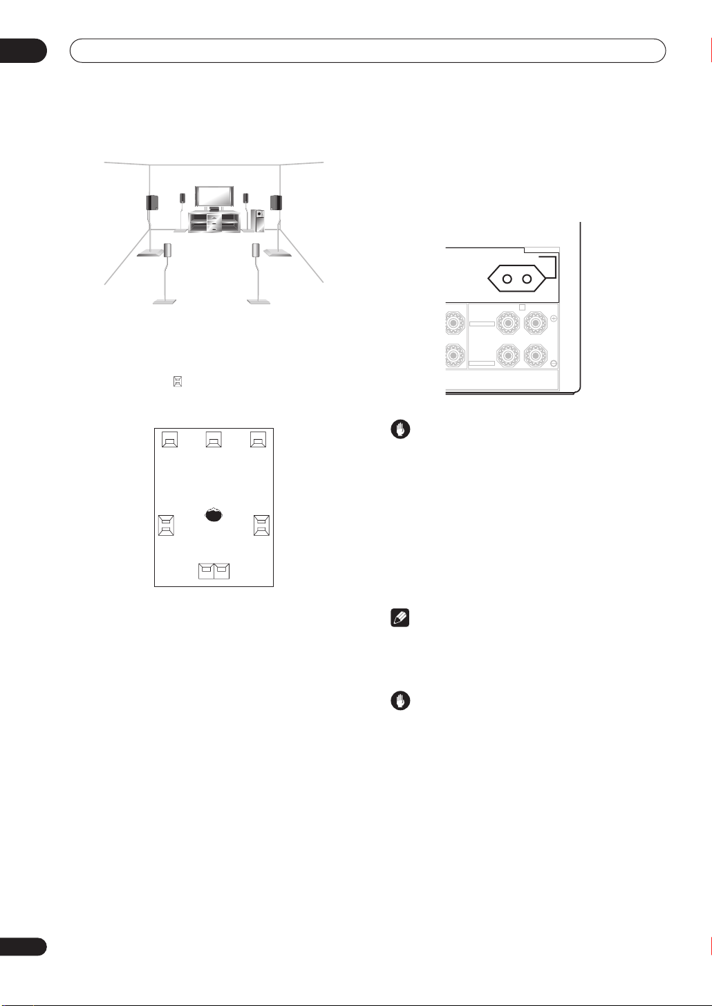
Overhead view of speaker setup
You can also refer to the 3-D speaker setup illustration on
page 10.
Front
Left
Surround
Left
Surround Back Surround Back
Single Surround Back Speaker
Center
Listening Position
Left Right
Front
Right
Subwoofer
Surround
Right
The diagrams below show suggested surround and
surround back speaker orientation. The first diagram (
A
) shows orientation with one surround back speaker (or
none) connected. The second (
fig. B
) shows orientation
fig.
with two surround back speakers connected.
90~120
LS
LS
LS
SB
fig. A
RS
RS
SBL
fig. B
SBL
0~60
SBR
SBR
RS
21
En
03
Connecting up
3-D view of
7.1 channel
speaker setup
THX speaker system setup
If you have a complete THX speaker system, follow the
diagram below to place your speakers. Note that the
surround speakers ( indicates bi-polar radiating
speakers) should output at an angle parallel to the
listener.
FL
LS
Surround
If you have two surround back speakers THX
recommends placing them together and the same
distance from your listening position so you can take
advantage of the ASA feature. For more details see
Advanced Speaker Array (ASA)
See also
Surround Back Speaker Position
make the settings that will give you the best sound
experience when using the Home THX modes (on
page 32).
CFR
RS
Surround
SBL SBR
Surround back
on page 76.
on page 48 to
AC outlet
Power supplied through this outlet is turned on and off by
the receiver's power switch. Total electrical power
consumption of connected equipment should not exceed
100 W.
AC OUTLET
SWITCHED 100W MAX
SURROUND BACK /
L
SELECTABLE
SELECTABLE
Caution
•
Do not connect a TV set
appliance to this unit's AC outlet.
• Do not connect appliances with high power
consumption to the AC outlet in order to avoid
overheating and fire risk. This can also cause the
receiver to malfunction.
• Since a subwoofer or power amplifier can exceed the
100W maximum when playing sources at a high
volume, this type of equipment should not be
connected to the AC outlet.
Note
• This unit should be disconnected by removing the
power plug from the wall socket when not in regular
use (ex. when on vacation).
Power cord caution
• Handle the power cord by the plug. Do not pull out
the plug by tugging the cord and never touch the
power cord when your hands are wet as this could
cause a short circuit or an electric shock. Do not
place the unit, a piece of furniture, etc., on the power
cord, or pinch the cord. Never make a knot in the cord
or tie it with other cords. The power cords should be
routed such that they are not likely to be stepped on.
A damaged power cord can cause a fire or give you
an electrical shock. Check the power cord once in a
while. When you find it damaged, ask your nearest
Pioneer authorized independent service company for
a replacement.
B
(
)
Single
R
L
, monitor, heater, or similar
22
En
Connecting up
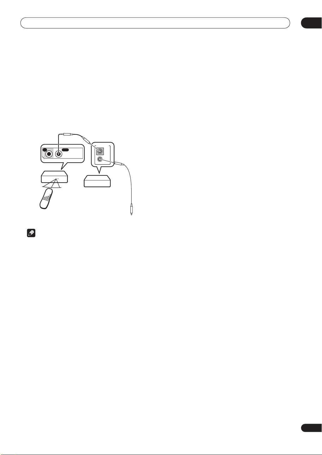
Operating other Pioneer components
Many Pioneer components have SR
which can be used to link components together so that
you can use just the remote sensor of one component.
When you use a remote control, the control signal is
passed along the chain to the appropriate component.
Note that if you use this feature,
have at least one set of analog audio or video jacks
connected
to another component for grounding
purposes.
CONTROL
jacks
make sure that you also
03
IN
Receiver
Remote
control
unit
OUT
CONTROL
Other Pioneer products
with CONTROL terminals
CONTROL
IN
OUT
Connect to CONTROL
terminal of other
Pioneer products
Note
• If you want to control all your components using this
receiver’s remote control, refer to
of your system
on page 54.
Controlling the rest
• If you have connected a remote control to the
CONTROL IN
jack (using a mini-plug cable), you
won't be able to control this unit using the remote
sensor.
23
En
04
Controls and displays
Chapter 4:
Controls and displays
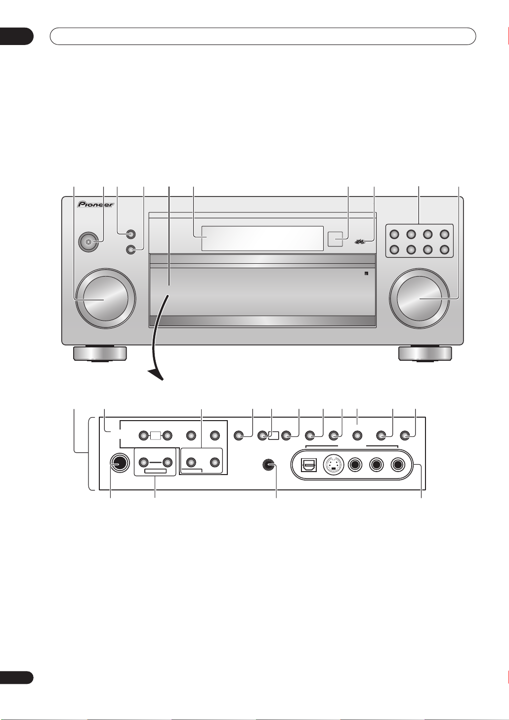
Front panel
1 1023 4 5 6 7 8 9
10
STANDBY/ON
MULTI JOG
11
LISTENING MODE
TUNER
CONTROL
PHONES
SELECT
ENTER
TUNER
EDIT
MULTI
JOG
SYSTEM
SETUP
MULTI JOG MULTI JOG
12 14 15 17 18 20
TUNING/
BAND MPX TONE
STATION
PTY
RETURN
SEARCH
EON
MIDNIGHT/
LOUDNESS
MULTI
JOG
MCACC
SETUP MIC
ACOUSTIC
DIALOG
ENHANCEMENT
EQ
DIGITAL IN S-VIDEO VIDEO
1613
MULTI CHINSIGNAL
VIDEO2 INPUT
AUDIO/VIDEO MULTI-CHANNEL RECEIVER
EXTENDED
SELECT
MODE
DVD/LD TV/SAT DVR/VCRVIDEO1
CD-R/
TAPE/MD
MASTER VOLUME
TUNERVIDEO2
CD
19
SPEAKERS
AUDIOLR
VSX-1015
24
En
24
23
22 21
 Loading...