


SC300
ORDER NO.
CRT2242
Se
r
v
i
c
e
M
a
nu
a
l
PUB. NO. CRT2242
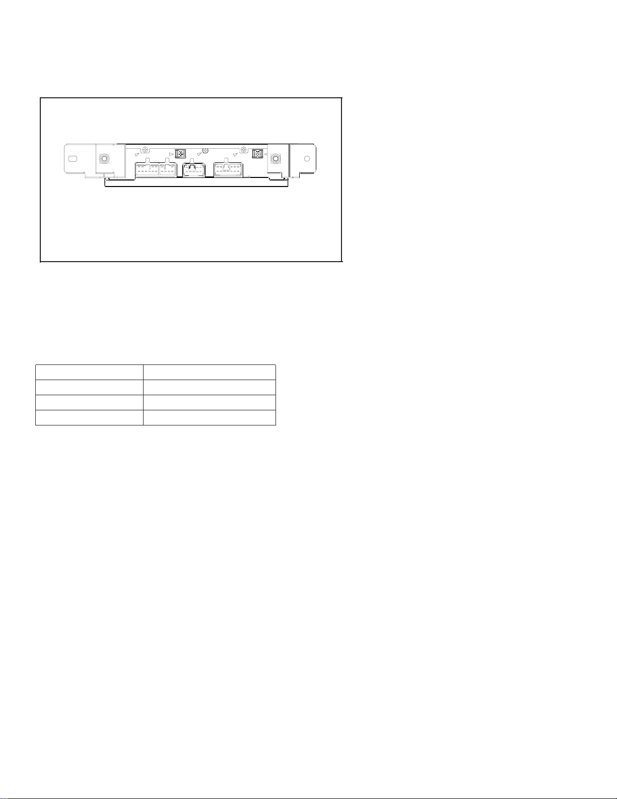
AUDIO SYSTEM
POWER AMPLIFIER
Manufactured for TOYOTA
by PIONEER ELECTRONIC CORPORATION
VEHICLE DESTINATION PRODUCED AFTER TOYOTA PART No. ID No. PIONEER MODEL No.
LEXUS SC300, U.S.A., CANADA August 1998 86280-24210 GM-8886ZT/UC,
LEXUS SC400 GM-8886ZT-91/UC
SC300,400
2
GM-8886ZT,8886ZT-91
1. SAFETY INFORMATION
This service manual is intended for qualified service technicians; it is not meant for the casual do-it-yourselfer.
Qualified technicians have the necessary test equipment and tools, and have been trained to properly and safely repair
complex products such as those covered by this manual.
Improperly performed repairs can adversely affect the safety and reliability of the product and may void the warranty.
If you are not qualified to perform the repair of this product properly and safely, you should not risk trying to do so
and refer the repair to a qualified service technician.
CONTENTS
1. SAFETY INFORMATION ............................................2
2. EXPLODED VIEWS AND PARTS LIST.......................3
3. SCHEMATIC DIAGRAM .............................................4
4. PCB CONNECTION DIAGRAM ................................10
5. ELECTRICAL PARTS LIST ........................................18
6. ADJUSTMENT..........................................................23
7. GENERAL INFORMATION .......................................25
7.1 IC.........................................................................25
7.2 DIAGNOSIS........................................................28
7.2.1 DISASSEMBLY..........................................28
7.2.2 CONNECTOR FUNCTION DESCRIPTION .......29
7.3 EXPLANATION...................................................30
7.3.1 BLOCK DIAGRAM.....................................30
7.3.2 SYSTEM BLOCK DIAGRAM.....................31
7.3.3 SERVICE MODE FOR DSP AMPLIFIER ....32
8. OPERATIONS AND SPECIFICATIONS.....................34
NOTE:
- The GM-8886ZT-91/UC is supplementary genuine part for a TOYOTA vehicle, and a PIONEER product for recycling
stock.
- As for the structure and electrical system, there is no difference between the GM-8886ZT-91/UC and GM-8886ZT/UC.
- The supplementary model is identical with the original ones except for the following items.
R1A
R3T
TLMT
E
R1H
FL+
RDK
RDH
FL-
RDL
RDJ
RDA
WF+
RDQ
WF-
RDM
RL-
RCZ
RR+
RDP
RL+
RCY
RR-
RDN
SGND
R8G
TXM-
ROY
TXM+
L+
R1L
R+
R1J
L-
R-
R1M
R1K
BUS-
BUS+
RDB
ACC
R1B
MUTE
R1D
CDR+
CDR-
UHY
UHZ
MUTE
R2N
SGD4
2CB
CDL+
UHO
CDL-
UH1
FR-
FR+
BU
GM-8886ZT/UC,
GM-8886ZT-91/UC
Description Part No.
Cover CEG1045
Carton CHA2114
Contain Box CHD2114
3
GM-8886ZT,8886ZT-91
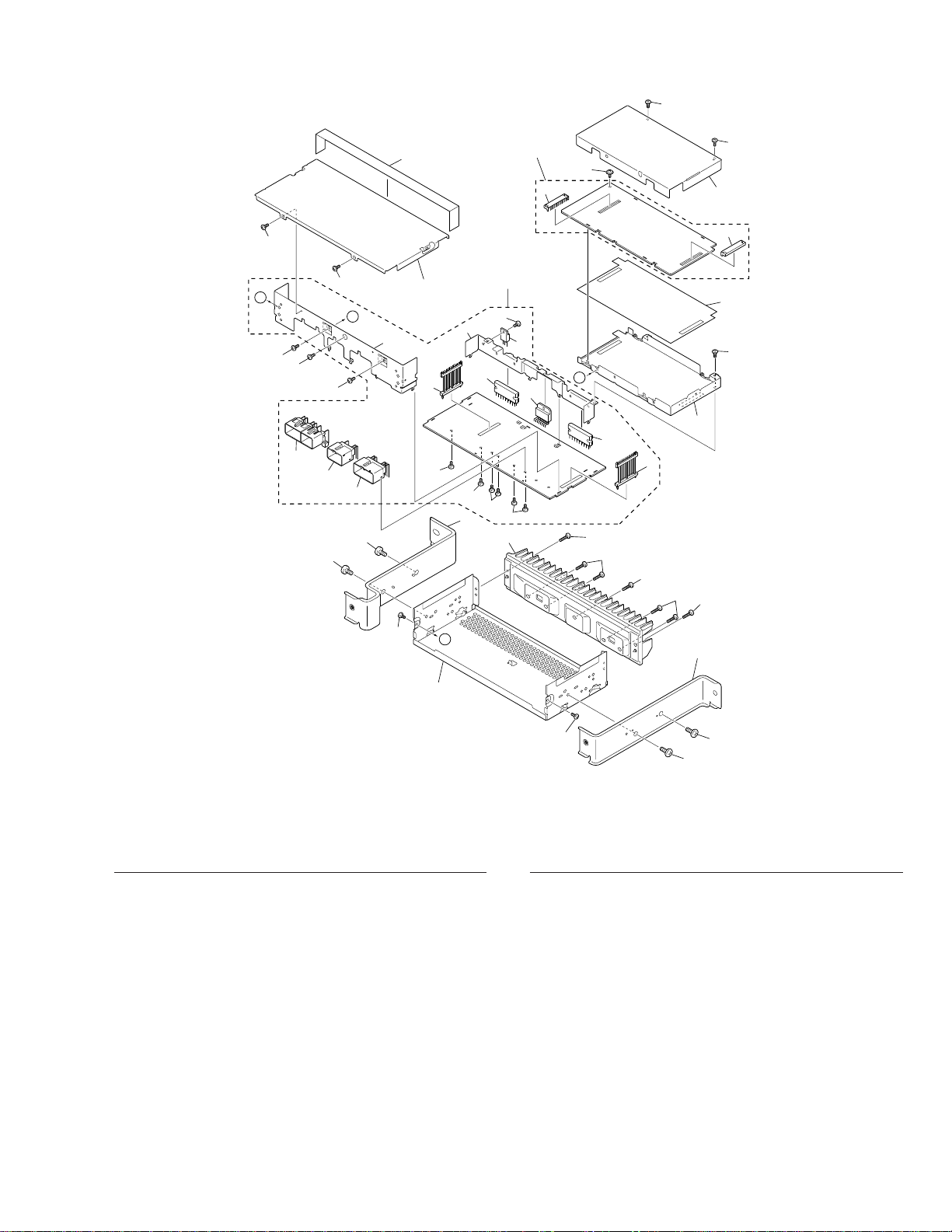
2. EXPLODED VIEWS AND PARTS LIST
2.1 EXTERIOR
A
A
B
B
1
1
1
1
1
15
16
17
2
2
1
4
1
2
2
9
11
3
3
3
3
3
8
14
14
14
14
18
29
28
27
30
6
1
10
24
19
5
26
13
21
20
12
23
22
25
7
1
1
NOTE:
- Parts marked by “*”are generally unavailable because they are not in our Master Spare Parts List.
- Screws adjacent to
∇ mark on the product are used for disassembly.
- EXTERIOR SECTION PARTS LIST
Mark No. Description Part No.
Mark No. Description Part No.
1 Screw BMZ30P060FMC
2 Screw BMZ50P080FMC
3 Screw CBA1327
4 Chassis CNA1852
5 Case CNB2102
6 Shield CNC6809
7 Shield CNC6810
8 Bracket CNC7486
9 Bracket CNC7487
10 Insulator CNM5537
11 Heat Sink CNR1432
12 Amp Unit CWM5682
13 Screw BMZ30P060FMC
14 Screw CBA1393
15 Connector(CN901) CKM1222
16 Connector(CN902) CKM1293
17 Connector(CN903) CKM1245
18 Plug(CN905) CKS3631
19 Plug(CN906) CKS3631
20 Bracket CNC6807
21 Holder CNC6808
22 DSP Unit CWM5683
23 Socket(CN51) CKS3632
24 Socket(CN52) CKS3632
25 Screw IMS30P060FMC
26 Seal CNM5381
27 IC(IC801) TA8221AH1
28 IC(IC821) PAL001A
29 IC(IC851) TA8225H-LF1
30 IC(IC901) NJM7805FA
4
GM-8886ZT,8886ZT-91
1
23
4
1
234
D
C
B
A
A
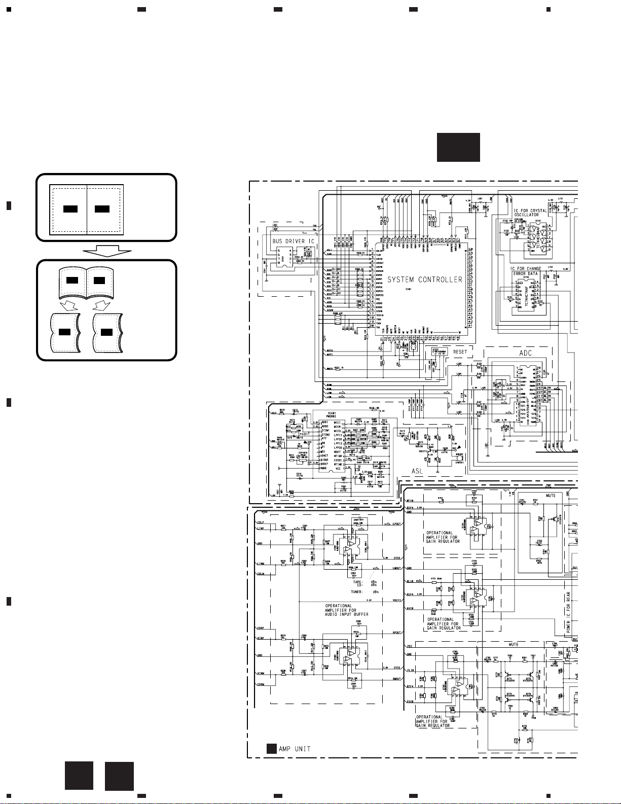
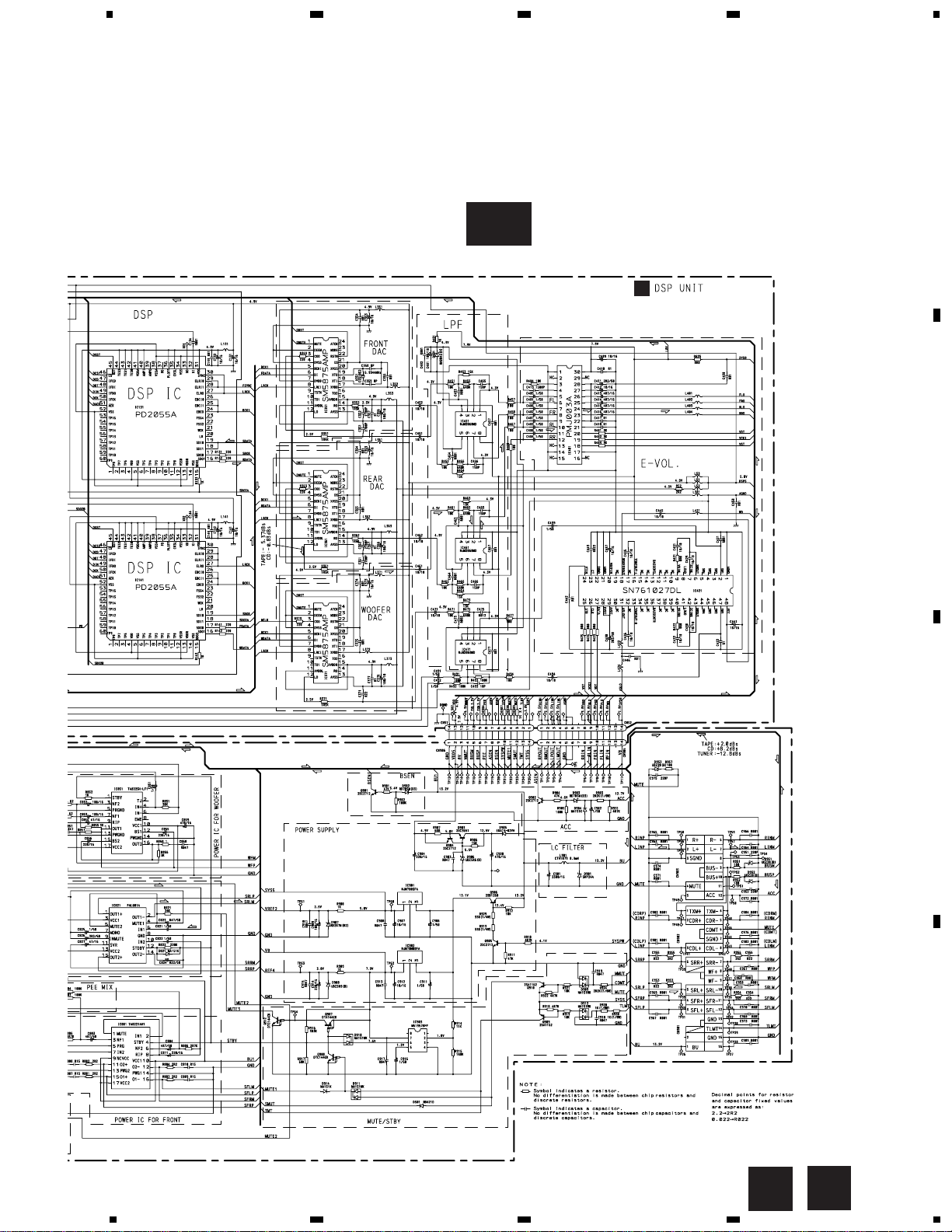
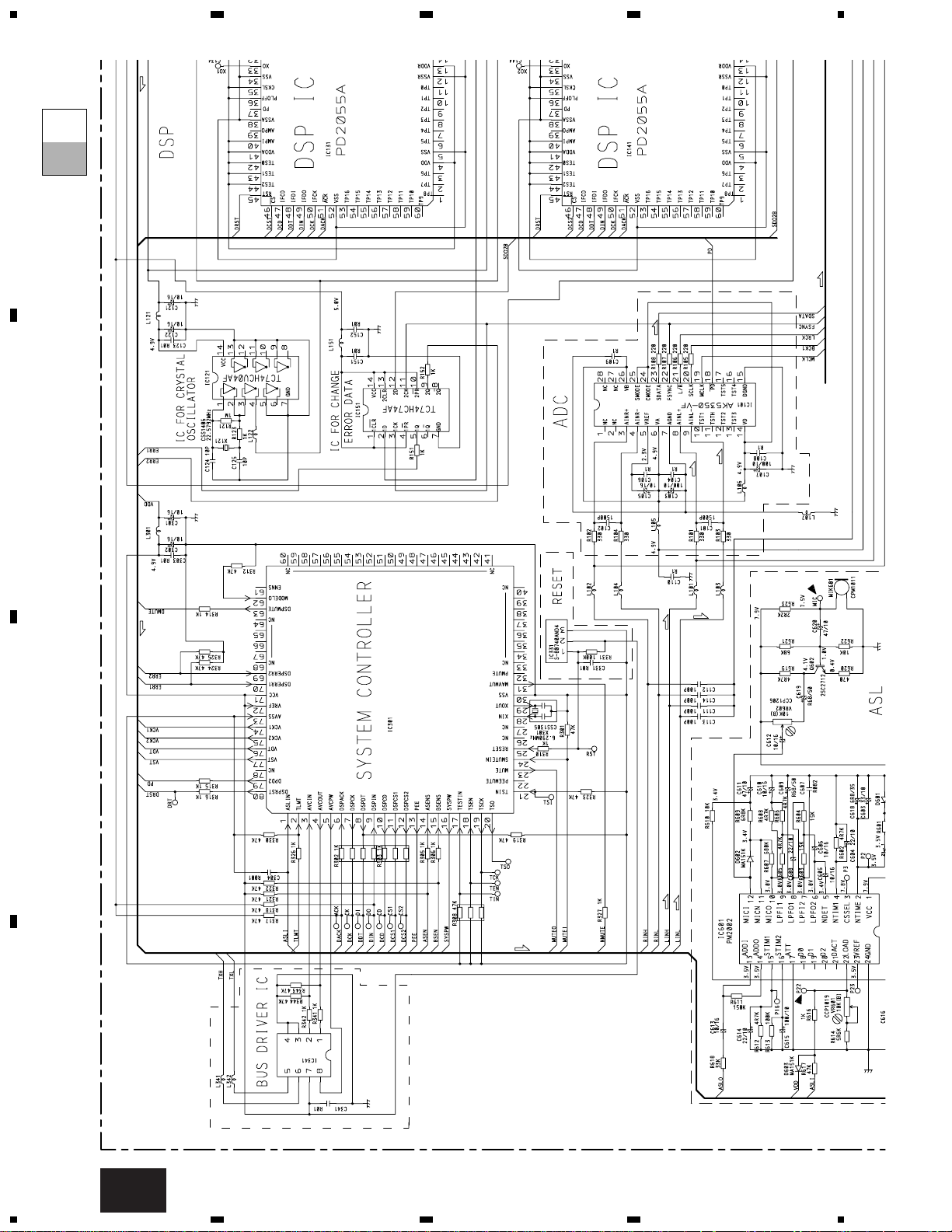
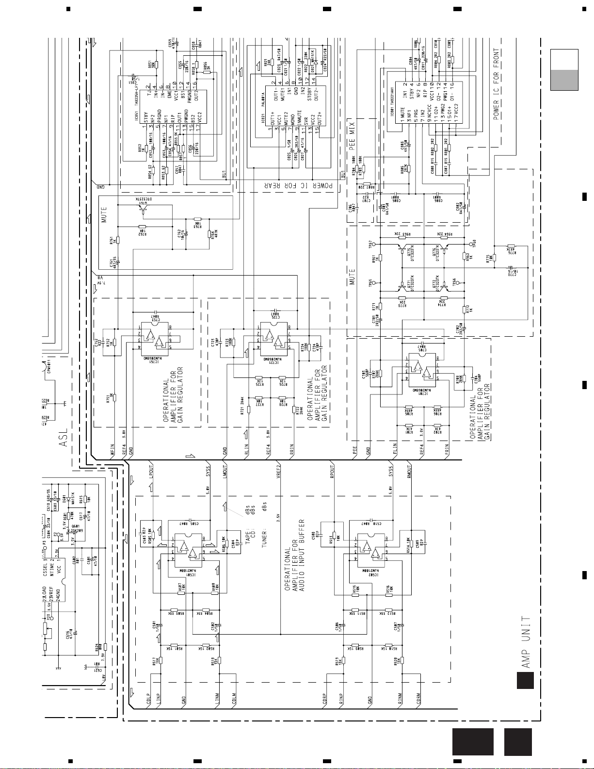
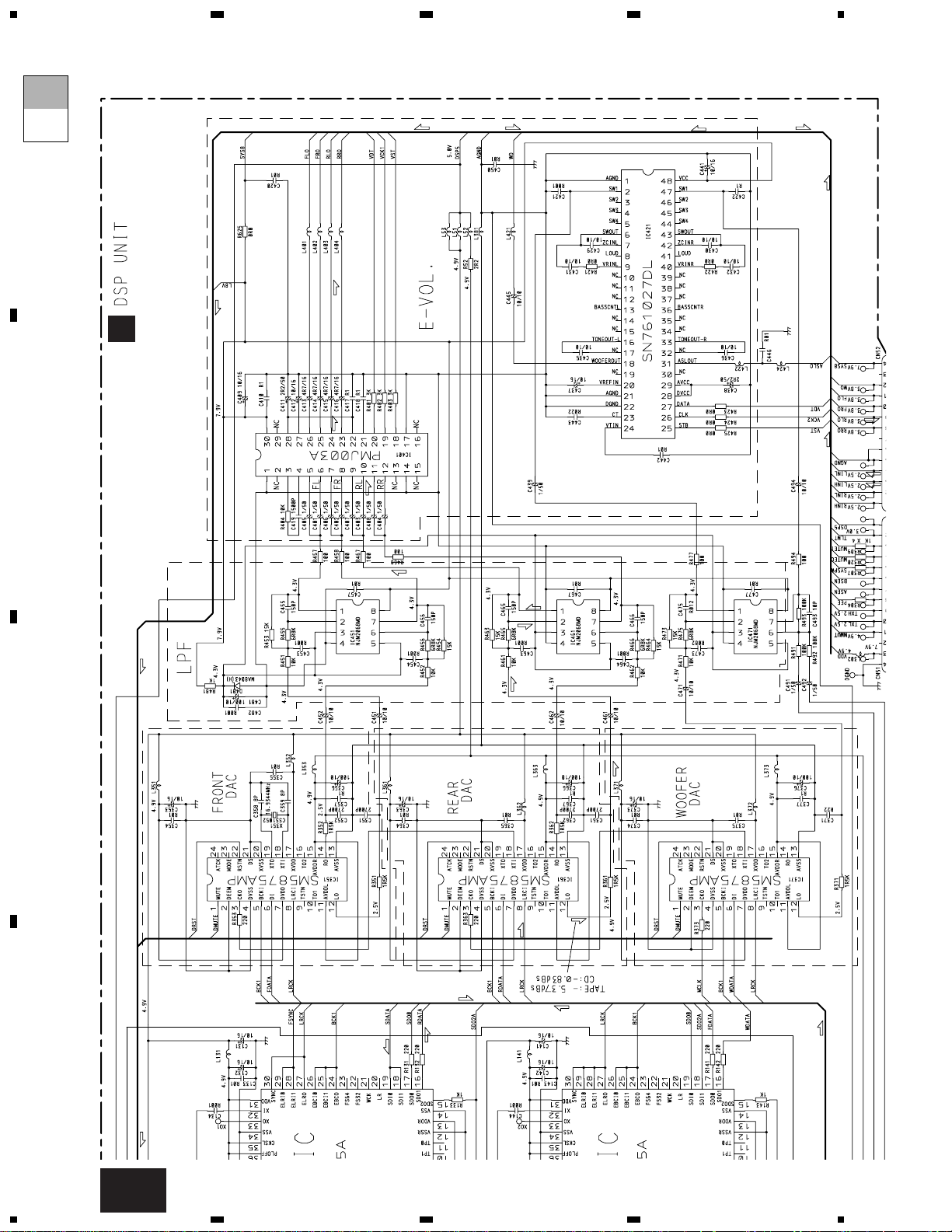
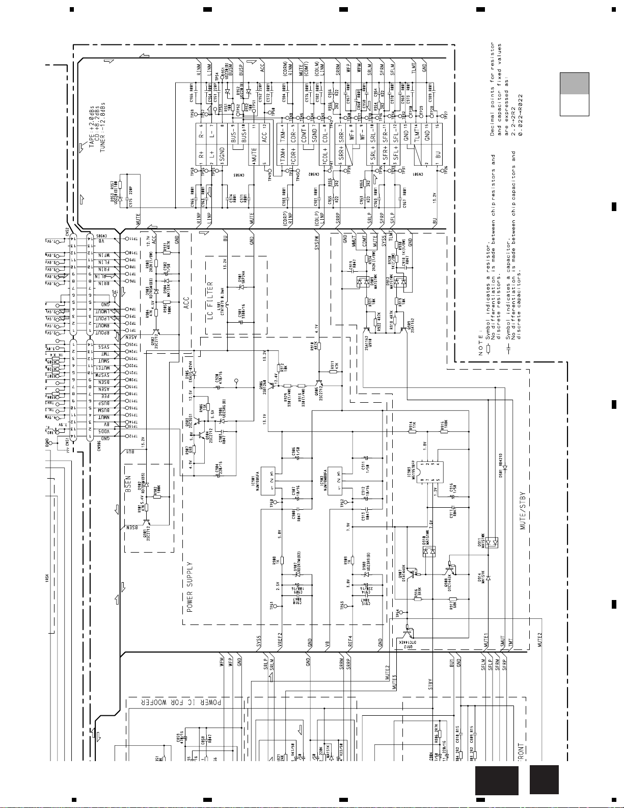
3. SCHEMATIC DIAGRAM
3.1 OVERALL CONNECTION DIAGRAM(GUIDE PAGE)
Note: When ordering service parts, be sure to refer to “EXPLODED VIEWS AND PARTS LIST” or “ELECTRICAL PARTS
LIST”.
B
PD5452A
+7.13
+0.93
-13.87
HA12187FP
A-a
A-a A-b
A-a
A-b
A-b
A-a
Large size
SCH diagram
Guide page
Detailed page
B
5
GM-8886ZT,8886ZT-91
5
6
78
5
6
78
D
C
B
A
A
A-b
A
B
6
GM-8886ZT,8886ZT-91
1
23
4
1
234
D
C
B
A
PD5452A
HA12187FP
A-a
A-a
A-b
7
GM-8886ZT,8886ZT-91
5
6
78
5
6
7
8
D
C
B
A
A-a
A-a
A-b
B
B
+7.13
+0.93
-13.87
8
GM-8886ZT,8886ZT-91
1
23
4
1
234
D
C
B
A
A-a
A-b
A-b
A
9
GM-8886ZT,8886ZT-91
5
6
78
5
6
7
8
D
C
B
A
A-b
A-a
A-b
B
10
GM-8886ZT,8886ZT-91
1
23
4
1
234
D
C
B
A
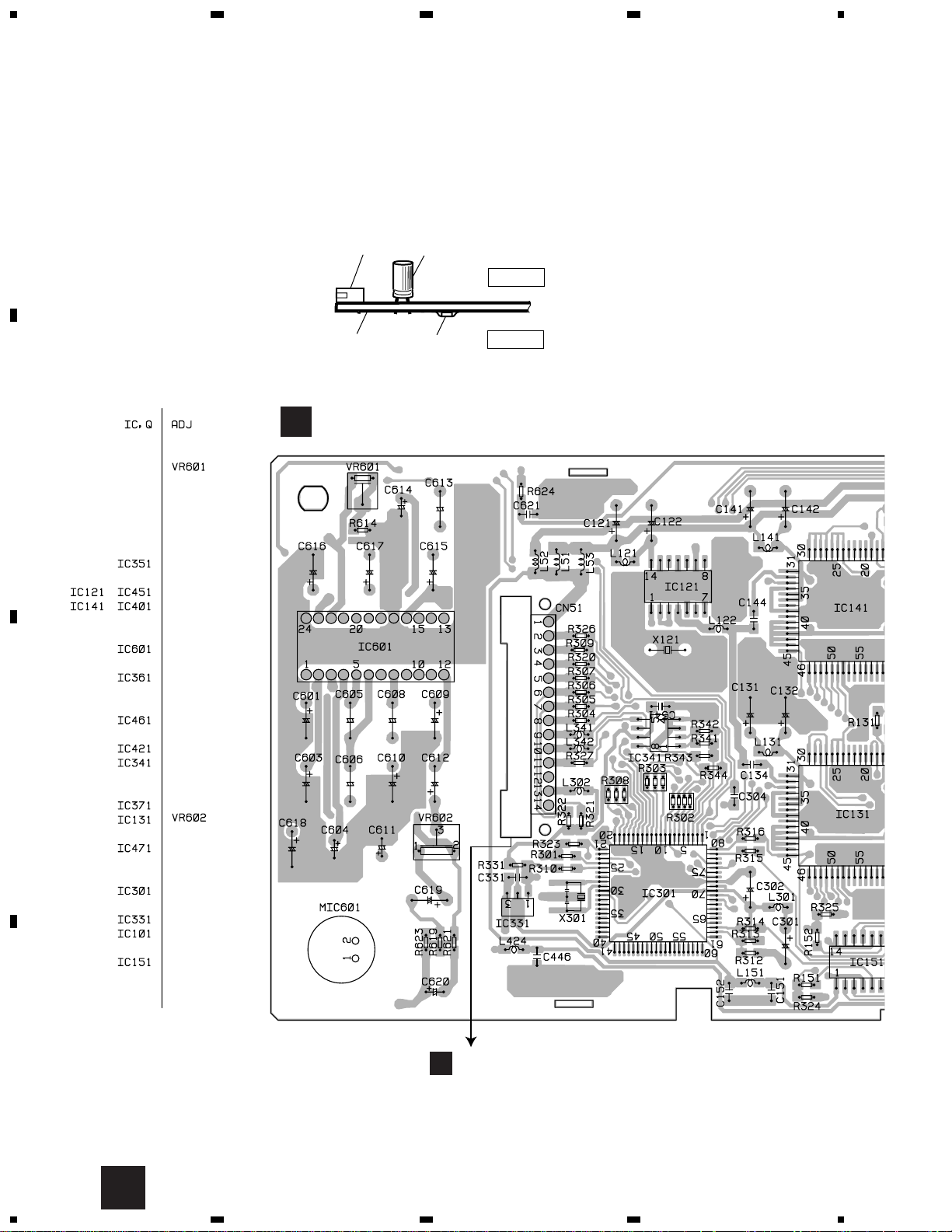
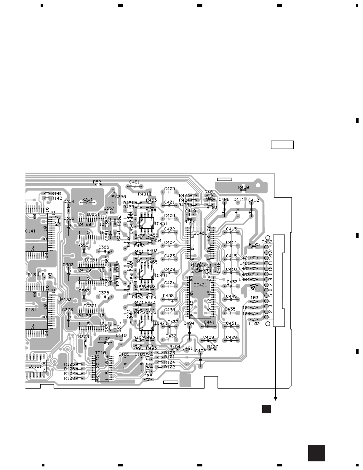
4. PCB CONNECTION DIAGRAM
4.1 DSP UNIT
NOTE FOR PCB DIAGRAMS
1. The parts mounted on this PCB
include all necessary parts for
several destination.
For further information for
respective destinations, be sure
to check with the schematic dia-
gram.
Capacitor
Connector
P.C.Board
Chip Part
SIDE A
SIDE B
A
2. Viewpoint of PCB diagrams
B
CN906
DSP UNIT
A
11
GM-8886ZT,8886ZT-91
5
6
78
5
6
7
8
D
C
B
A
A
SIDE A
B
CN905
 Loading...