

Page 1

PLASMA DISPLAY
ÉCRAN À PLASMA
PLASMA-DISPLAY
PDP-615EX
Operating Instructions
Mode d’emploi
Bedienungsanleitung
Page 2

Operating Instructions
Thank you very much for purchasing this PIONEER product.
Before using your Plasma Display, please carefully read the
“Important Information” and these “Operating Instructions” so
you will know how to operate the Plasma Display properly.
Keep this manual in a safe place. You will find it useful in the
future.
English
Notes on Installation Work:
This product is marketed assuming that it is installed by qualified
personnel with enough skill and competence. Always have an
installation specialist or your dealer install and set up the product.
PIONEER cannot assume liabilities for damage caused by mistake
in installation or mouting, misuse, modification or a natural disaster.
Note for Dealers:
After installation, be sure to deliver this manual to the customer
and explain to the customer how to handle the product.
En
Page 3

Important Information
Precautions
Please read this manual carefully before using your plasma
monitor and keep the manual handy for future reference.
English
CAUTION:
TO PREVENT FIRE OR SHOCK HAZARDS, DO NOT EXPOSE
THIS UNIT TO RAIN OR MOISTURE. ALSO DO NOT USE
THIS UNIT’S POLARIZED PLUG WITH AN EXTENSION CORD
RECEPTACLE OR OTHER OUTLETS, UNLESS THE
PRONGS CAN BE FULLY INSERTED. REFRAIN FROM
OPENING THE CABINET AS THERE ARE HIGH-VOLTAGE
COMPONENTS INSIDE. REFER SERVICING TO QUALIFIED
SERVICE PERSONNEL.
Important Information
CAUTION
RISK OF ELECTRIC SHOCK
DO NOT OPEN
TO REDUCE THE RISK OF ELECTRIC
SHOCK, DO NOT REMOVE COVER. NO
USER-SERVICEABLE PARTS INSIDE.
REFER SERVICING TO QUALIFIED
SERVICE PERSONNEL.
This symbol warns the user that uninsulated
voltage within the unit may have sufficient
magnitude to cause electric shock.
Therefore, it is dangerous to make any kind
of contact with any part inside of this unit.
This symbol alerts the user that important
literature concerning the operation and
maintenance of this unit has been included.
Therefore, it should be read carefully in
order to avoid any problems.
WARNING
Warnings and Safety Precaution
This plasma monitor is designed and
manufactured to provide long, trouble-free service.
No maintenance other than cleaning is required.
Please see the section “Plasma monitor cleaning
procedure” on the next page.
The plasma display panel consists of fine picture
elements (cells) with more than 99.99 percent active
cells. There may be some cells that do not produce
light or remain lit.
For operating safety and to avoid damage to the unit,
read carefully and observe the following instructions.
To avoid shock and fire hazards:
1. Provide adequate space for ventilation to av oid internal
heat build-up. Do not cover rear vents or install the unit
in a closed cabinet or shelves.
If you install the unit in an enclosure, make sure there
is adequate space at the top of the unit to allow hot air
to rise and escape. If the monitor becomes too hot, the
overheat protector will be activ ated and the monitor will
be turned off. If this happens, turn off the power to the
monitor and unplug the power cord. If the room where
the monitor is installed is particularly hot, move the
monitor to a cooler location, and wait for 60 minutes to
cool the monitor. If the problem persists, contact your
dealer for service.
2. Do not use this unit’s polarized plug with extension cords
or outlets unless the prongs can be completely inserted.
3. Do not expose the unit to water or moisture.
4. Avoid damage to the power cord, and do not attempt to
modify the power cord.
5. Unplug the power cord during electrical storms or if
the unit will not be used over a long period.
6. Do not open the cabinet which has potentially dangerous
high voltage components inside. If the unit is damaged in
this way the warranty will be void. Moreover, there is a
serious risk of electric shock.
7. Do not attempt to service or repair the unit. The
manufacturer is not liable for any bodily harm or damage
caused if unqualified persons attempt service or open
the back cover. Refer all service to authorized Service
Centers.
2Eni
En
Page 4

NOTE:
When you connect a computer to this monitor, use an RGB
cable including the ferrite core on both ends of the cable.
If you do not do this, this monitor will not conform to
mandatory CE or C-Tick standards.
Attaching the ferrite cores:
Set the ferrite cores on both ends of the power cable
(supplied).
Close the lid tightly until the clamps click.
Power cable (supplied)
core
core
To avoid damage and prolong operating life:
1. Use only with 220-240 V 50/60Hz AC power supply.
Continued operation at line voltages greater than 220240 Volts AC will shorten the life of the unit, and might
even cause a fire hazard.
2. Handle the unit carefully when installing it and do not
drop.
3. Set the unit away from heat, excessive dust, and direct
sunlight.
4. Protect the inside of the unit from liquids and small
metal objects. In case of accident, unplug the power
cord and have it serviced by an authorized Service
Center.
5. Do not hit or scratch the panel surface as this causes
flaws on the surface of the screen.
6. For correct installation and mounting it is strongly
recommended to use a trained, authorized dealer.
7. As is the case with any phosphor-based display (like a
CRT monitor, for example) light output will gradually
decrease over the life of a Plasma Display Panel.
8. To a void sulfurization it is strongly recommended not to
place the unit in a dressing room in a public bath or hot
spring bath.
9. Do not use in a moving vehicle, as the unit could drop or
topple over and cause injuries.
10. Do not place the unit on its side, upside-down or with the
screen facing up or down, to av oid combustion or electric
shock.
Recommendations to avoid or minimize phosphor burn-in:
Like all phosphor-based display devices and all other gas
plasma displays, plasma monitors can be susceptible to
phosphor burn under certain circumstances. Certain
operating conditions, such as the continuous display of a
static image over a prolonged period of time, can result in
phosphor burn if proper precautions are not taken. T o protect
your investment in this plasma monitor , please adhere to the
following guidelines and recommendations for minimizing
the occurrence of image burn:
* Always enable and use your computer’s screen saver
function during use with a computer input source.
* Display a moving image whenever possible.
* Change the position of the menu display from time to time.
* Always power down the monitor when you are finished
using it.
If the plasma monitor is in long term use or continuous
operation take the following measures to reduce the
likelihood of phosphor burn:
* Lower the Brightness and Contrast levels as much as
possible without impairing image readability .
* Display an image with many colors and color gradations
(i.e. photographic or photo-realistic images).
* Create image content with minimal contrast between light
and dark areas, for example white characters on black
backgrounds. Use complementary or pastel color whenever
possible.
* Avoid displaying images with few colors and distinct,
sharply defined borders between colors.
Note:
*
Burn-in is not covered by the warranty.
Contact your dealer for other recommended procedures that
will best suit your particular application needs.
CAUTION:
WHEN POSITIONING THIS EQUIPMENT ENSURE THAT
THE MAINS PLUG AND SOCKET IS EASILY ACCESSIBLE.
English
Important Information
Plasma monitor cleaning procedure:
1. Use a wiping cloth (attached) or a soft dry cloth to clean
the front panel and bezel area. Never use solvents such as
alcohol or thinner to clean these surfaces.
2. Clean plasma ventilation areas with a vacuum cleaner
with a soft brush nozzle attachment.
3. To ensure proper ventilation, cleaning of the ventilation
areas must be carried out monthly. More frequent cleaning
may be necessary depending on the environment in which
the plasma monitor is installed.
3Enii
En
Page 5

English
This product complies with the Low Voltage Directive
(73/23/EEC, amended by 93/68/EEC), EMC Directives
(89/336/EEC, amended by 92/31/EEC and 93/68/EEC).
Caution
This model is for use with the following optional accessories.
Use with other optional accessories is capable of resulting in
instability causing possible injury.
Table top stand: PDK-1014
Wall mount unit: PDK-WM03
Important Information
4Eniii
En
Page 6

Contents
Installation ...................................................... 2
Ventilation Requirements for enclosure mounting .......... 2
How to use the safety metal fittings and the screws for
safety metal fittings................................................ 2
Cable Management.................................................. 3
How to use the remote control.................................... 3
Battery Installation and Replacement ...........................3
Operating Range .......................................................... 3
Handling the remote control......................................... 3
Part Names and Function .................................. 4
Front View .............................................................. 4
Rear View/ Terminal Board ....................................... 5
Remote Control ........................................................ 6
Basic Operations............................................... 7
POWER .................................................................. 7
T o turn the unit ON and OFF: ...................................... 7
VOLUME ................................................................ 7
T o adjust the sound v olume:.........................................7
MUTING................................................................. 7
T o mute the sound:.......................................................7
DISPLAY .................................................................. 7
T o check the settings:................................................... 7
DIGITAL ZOOM ....................................................... 7
OFF TIMER .............................................................. 7
T o set the off timer: ...................................................... 7
T o check the remaining time: .......................................7
T o cancel the off timer: ................................................7
WIDE Operations............................................... 8
SCREEN SIZE Operation (manual) ............................. 8
When viewing videos or digital video discs .................8
SCREEN SIZE Operation with Computer Signals .......... 9
SPLIT SCREEN Operations ................................. 10
Showing a couple of pictures on the screen at the
same time .......................................................... 10
Operations in the Side-by-side mode.......................... 10
Operations in the Picture-in-picture mode .................. 11
Selecting the input signals to be displayed .................11
Zooming up pictures .................................................. 11
Adjusting the OSD controls ....................................... 11
OSD (On Screen Display) Controls ..................... 12
Menu Operations ................................................... 12
Setting the language for the menus........................... 12
Menu Tree ............................................................. 13
Picture Settings Menu.............................................. 15
Storing picture settings............................................... 15
Adjusting the picture.................................................. 15
Reducing noise in the picture ..................................... 15
Setting the color temperature .....................................16
Adjusting the color to the desired level ......................16
Changing the Gamma Curve ......................................16
Making the Low Tone adjustments............................. 16
Adjusting the pedestal level (black lev el) ................... 17
Adjusting the colors ................................................... 17
Setting the picture to suit the movie ........................... 17
Setting the picture modes according to the brightness of
the room .................................................................. 17
SOUND Settings Menu ........................................... 18
Adjusting the treble, bass and left/right balance and
audio input select..................................................... 18
Setting the allocation of the audio connectors ............18
SCREEN Settings Menu ........................................... 18
Adjusting the Position, Size, PHASE, CLOCK ...............
18
SET UP Settings Menu ............................................. 19
Setting the PC2/COMPONENT2 connectors ............. 19
Setting the PC1 connector ..........................................19
Setting high definition images to the suitable screen size ....
Setting a computer image to the correct RGB select
screen ...................................................................... 19
Setting the black level for HDMI signal ..................... 20
Setting the video signal format................................... 20
Setting the background color when no signal is being
input ........................................................................ 20
Setting the gray level for the SIDE MASK................. 21
Setting the screen size for S1/S2 video input ..............21
Turning on/off the information display....................... 21
Setting the position of the menu ................................. 21
Resetting to the default values.................................... 21
Function Settings Menu ........................................... 22
Setting the power management for computer images .....
STANDBY/ON indicator ........................................... 22
Setting the Input Skip................................................. 22
Erasing the sub screen image when there is no input
signal....................................................................... 22
Displaying the entire image during DIGITAL ZOOM
operations................................................................ 23
Displaying still images in the sub screen .................... 23
Reducing burn-in of the screen ..................................23
Signal Information Menu ......................................... 25
Checking the frequencies, polarities of input signals,
and resolution .......................................................... 25
19
22
Pin Assignments ............................................. 26
mini D-Sub 15-pin connector (Analog) ..................... 26
Table of Signals Supported .............................. 27
Supported resolution .............................................. 27
Troubleshooting.............................................. 29
Specifications ................................................. 30
Contents of the Package
Plasma monitor
Power cord
Remote control with two AAA Batteries
Manual
W arranty
Safety metal fittings (2pcs)*
Ferrite cores (2pcs)
Cable clamps (5pcs)
Wiping cloth
* These are fittings for fastening the unit to a wall to prevent
tipping due to external shock when using the stand
(optional). Fasten the safety fittings to the holes in the
back of the monitor using the safety fitting mount screws
(see page 2).
Options
• Wall mount unit
• Stand
English
Contents
1
En
Page 7
English
Installation
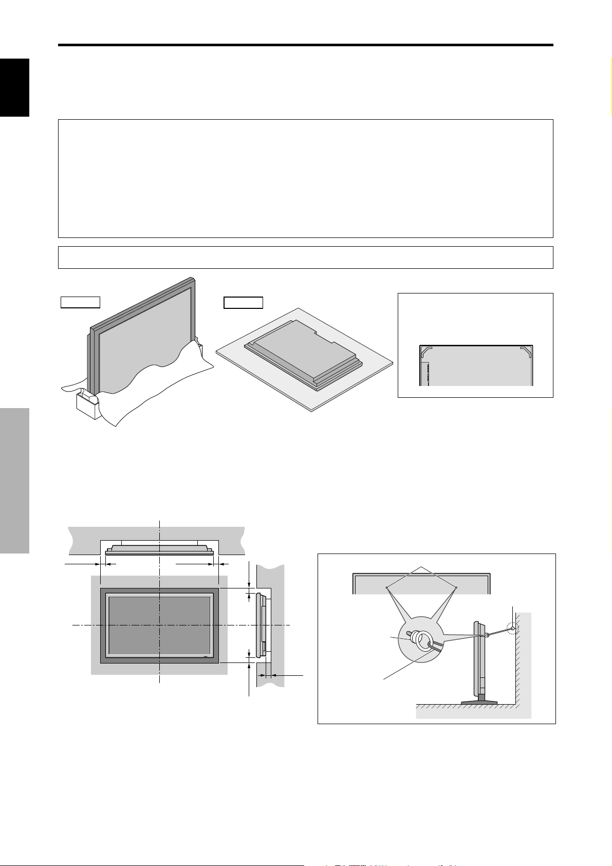
You can attach your optional mounts or stand to the plasma monitor in one of the following two ways:
* While it is upright. (See Drawing A)
* As it is laid down with the screen face down (See Drawing B). Lay the protective sheet, which was wrapped around the
monitor when it was packaged, beneath the screen surface so as not to scratch the screen face.
* Do not touch or hold the screen face when carrying the unit.
• This device cannot be installed on its own. Be sure to use a stand or original mounting unit. (Wall
mount unit, Stand, etc.)
* See page 1.
• For correct installation and mounting it is strongly recommended to use a trained, authorized
dealer.
Failure to follow correct mounting procedures could result in damage to the equipment or injury
to the installer.
Product warranty does not cover damage caused by improper installation.
* Use only the mounting kit or stand provided by manufacturer and listed under Options.
Installation
Drawing A
Drawing B
Ventilation Requirements for
enclosure mounting
T o allow heat to disperse, leav e space between surrounding
objects as shown on the diagram below when installing.
Wall
50mm (2")
50mm (2")
(2")
mm
Wall
When installing or carrying, use the
handles attached to the upper back
of the display.
How to use the safety metal fittings
and the screws for safety metal
fittings
These are fittings for fastening the unit to a wall to pre vent
tipping due to external shock when using the stand
(optional). Fasten the safety fittings to the holes in the
back of the monitor using the safety fitting mount screws.
Screw hole
Screw or Hook etc.
(Not supplied)
2
En
Safty metal fittings
50mm (2")
(2") 50
mm
50
Metal chain
(Not supplied)
Ta bl e To p
Wall
Page 8

Cable Management
Using the cable clamps provided with the plasma display ,
bundle at the back of the unit the signal and audio cables
connected to the display.
Back of the unit
mounting holes
To attach
1. 2.
clamp
cables
mounting hole
To detach
Operating Range
* Use the remote control within a distance of about 7 m/
23ft. from the front of the monitor’s remote control sensor
and at horizontal and vertical angles of up to approximately
30°.
* The remote control operation may not function if the
monitor’s remote control sensor is exposed to direct
sunlight or strong artificial light, or if there is an obstacle
between the sensor and the remote control.
English
How to use the remote control
Battery Installation and Replacement
Insert the 2 “AAA” batteries, making sure to set them in
with the proper polarity.
1.Press and open the cover.
2.Align the batteries according to the (+) and (–) indication
inside the case.
Handling the remote control
• Do not drop or mishandle the remote control.
• Do not get the remote control wet. If the remote control
gets wet, wipe it dry immediately.
• Avoid heat and humidity.
• When not using the remote control for a long period,
remove the batteries.
• Do not use new and old batteries together , or use different
types together.
• Do not take apart the batteries, heat them, or throw them
into a fire.
• When disposing of used batteries, please comply with
governmental regulations or environmental public
instruction’s rules that apply in your country/area.
Installation
3.Replace the cover.
3
En
Page 9

English
Part Names and Function
Front View
q Power ( )
Turns the monitor’s power on and off.
w Remote sensor window
Part Names and Function
Receives the signals from the remote control.
e STANDBY/ON indicator
When the power is on ............................. Lights green.
When the power is in the standby mode ... Lights red.
r INPUT/EXIT
Switches the input.
The available inputs depend on the setting of “BNC
INPUT”, “D-Sub INPUT” and “RGB SELECT”.
Functions as the EXIT buttons in the On-Screen
Display (OSD) mode.
Note:
output signal, which is RGB with composite sync.
Your dealer can supply a special SCART cable, which will enable you to use the RGB with composite sync signal.
To obtain the special cable as well as for further information, please contact your dealer.
Please refer to page 19 for selection of the correct mode in the on-screen display.
This plasma monitor has the capasity to display images when connected to European DVD players with a SCART
t and
Functions as the CURSOR ( / ) buttons in the OnScreen Display (OSD) mode.
y VOLUME
Adjusts the volume. Functions as the CURSOR (▲/
▼) buttons in the On-Screen Display (OSD) mode.
u MENU/SET
Sets the On-Screen Display (OSD) mode and displays
the main menu.
and
WARNING
The Power on/off switch does not disconnect the plasma
display completely from the supply mains.
4
En
Page 10
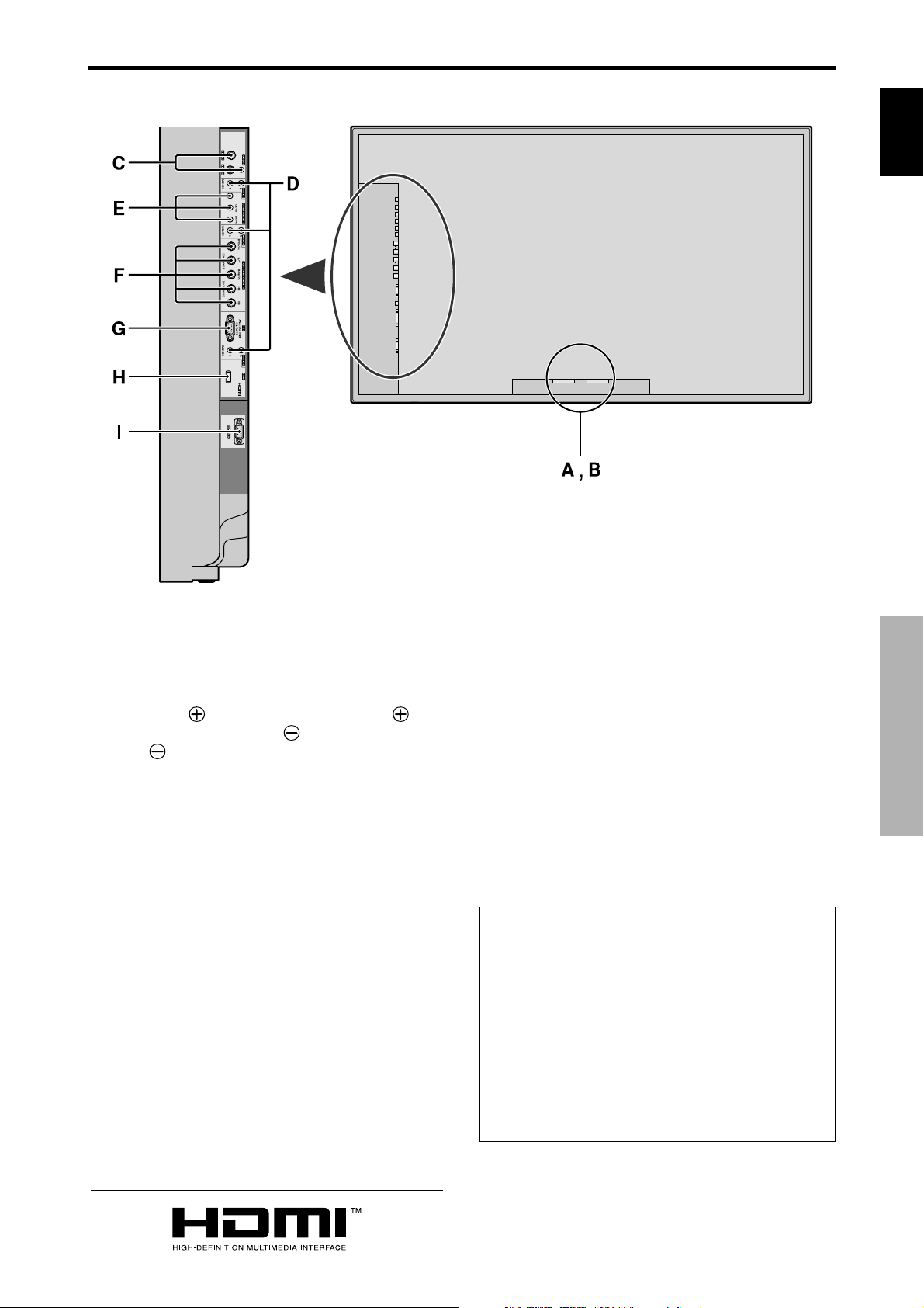
Rear View/ Terminal Board
English
A AC IN
Connect the included power cord here.
B EXT SPEAKER L and R
Connect speakers here. Maintain the correct polarity.
Connect the
SPEAKER terminal and the
to the
(positive) speaker wire to the EXT
(negative) speak er wire
EXT SPEAKER terminal on both LEFT and
RIGHT channels.
Please refer to your speaker’s owner’s manual.
C VIDEO1, 2, 3 (BNC, RCA, S-Video)
Connect VCR’s, DVD’s or Video Cameras, etc. here.
D AUDIO1, AUDIO2, AUDIO3
These are audio input terminals.
The input is selectable. Set which video image to allot
them from the SOUND menu screen.
E COMPONENT 1
Connect DVD’s, High Definition or Laser Discs, etc.
here.
F PC2/ COMPONENT2
PC2: You can connect an analog RGB
signal and the syncronization signal.
COMPONENT2: You can connect DVDs, High
Definition sources, Laser Discs, etc.
here.
This input can be set for use with an
RGB or component source (see page
19).
G PC1 (D-Sub)
Connect an analog RGB signal from a computer, etc.
here.
H HDMI
Connect a digital signal from a source with a HDMI
output.
See page 30 for the details of Supported Signals.
I RS-232C
Never connect any component to this connector
without first consulting your Pioneer installation
technician.
This connector is used for plasma display setup
adjustments.
Information
• For Y/CB/Cr , connect to the COMPONENT1 or PC2/
COMPONENT2 terminals.
• For SCAR T , this unit provides three ways to connect:
· SCART1: Connect R/G/B and composite sync. to
the PC2/COMPONENT2 terminals. (R, G, B and
HD connector)
· SCART2: Connect R/G/B to the COMPONENT2
terminals and composite sync. to the VIDEO1
terminal.
· SCART3: Connect R/G/B and composite sync. to
the PC1 terminal.
Part Names and Function
HDMI, the HDMI logo and High-Definition Multimedia Interface are
trademarks or registered trademarks of HDMI Licensing LLC.
5
En
Page 11
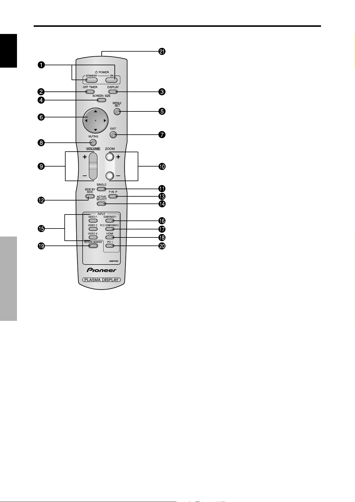
Remote Control
English
Part Names and Function
q POWER ON/STANDBY
Switches the power on/standby.
(This does not operate when ST ANDBY/ON indicator
of the main unit is off.)
w OFF TIMER
Activates the off timer for the unit.
e DISPLAY
Displays the source settings on the screen.
r SCREEN SIZE
Automatically detects the signal and sets the aspect
ratio.
SCREEN SIZE button is not active for all signals.
t MENU/SET
Press this button to access the OSD controls.
Press this button during the display of the main menu
to go to the sub menu.
y CURSOR (▲ / ▼ /
Use these buttons to select items or settings and to
adjust settings or switch the display patterns.
u EXIT
Press this button to exit the OSD controls in the main
menu. Press this button during the display of the sub
6
En
menu to return to the previous menu.
i MUTING
Mutes the sound.
o VOLUME (+ /–)
Adjusts the sound volume.
!0 ZOOM (+ /–)
Enlarges or reduces the image.
!1 SINGLE
Cancels the split screen mode.
!2 SIDE BY SIDE
Press this button to show a couple of pictures in the
side-by-side mode.
!3 P IN P
Press this button to show a couple of pictures in the
picture-in-picture mode.
!4 ACTIVE SELECT
Press this button to make the desired picture activate
during split screen mode.
When the PICTURE FREEZE function is operating,
this button can be used to display still images on the
subscreen.
!5 VIDEO1, 2, 3
Press these buttons to select the input directly.
These inputs can also be selected using the INPUT/
EXIT button on the monitor.
!6 COMPONENT1
Press this button to select the input directly.
This input can also be selected using the INPUT/EXIT
button on the monitor.
!7 PC2/COMPONENT2
Press this button to select the input directly.
This input can also be selected using the INPUT/EXIT
button on the monitor.
!8 HDMI
Press this button to select the input directly.
This input can also be selected using the INPUT/EXIT
button on the monitor.
See page 30 for the details of Supported Signals.
!9 PICTURE MEMORY
Switches sequentially between picture memory settings
1 to 6.
@0 PC1
Press this button to select the input directly.
This input can also be selected using the INPUT/EXIT
button on the monitor.
@1 Remote control signal transmitter
Transmits the remote control signals.
/ )
Page 12
Basic Operations
POWER
To turn the unit ON and OFF:
1. Plug the power cord into an active AC power outlet.
2. Press the Power button (on the unit).
The monitor’s STANDBY/ON indicator turns red and
the standby mode is set.
3. Press the POWER ON button (on the remote control)
to turn on the unit.
The monitor’s STANDBY/ON indicator will light up
(green) when the unit is on.
4. Press the POWER STANDBY button (on the remote
control) or the Power button (on the unit) to turn of f the
unit.
The monitor’s STANDBY/ON indicator turns red and
the standby mode is set (only when turning off the unit
with the remote control).
VOLUME
To adjust the sound volume:
1. Press and hold the VOLUME button (on the remote
control or the unit) to increase to the desired level.
2. Press and hold the VOLUME
control or the unit) to decrease to the desired level.
button (on the remote
MUTING
To mute the sound:
Press the MUTING button on the remote control to mute
the sound press again to restore.
DISPLAY
To check the settings:
1. The screen changes each time the DISPLAY button is
pressed.
2. If the button is not pressed for approximately three
seconds, the menu turns off.
DIGITAL ZOOM
Digital zoom specifies the picture position and enlarges
the picture.
1. (Be sure ZOOM NAV is off)
Press the ZOOM (+ or -) button to display magnifying
glass. (
To change the size of the picture:
Press the ZOOM+ button and enlarge the picture.
A press of the ZOOM- button will reduce the picture
and return it to its original size.
To change the picture position:
Select the position with the ▲▼
2. Press the EXIT button to delete the pointer.
)
buttons.
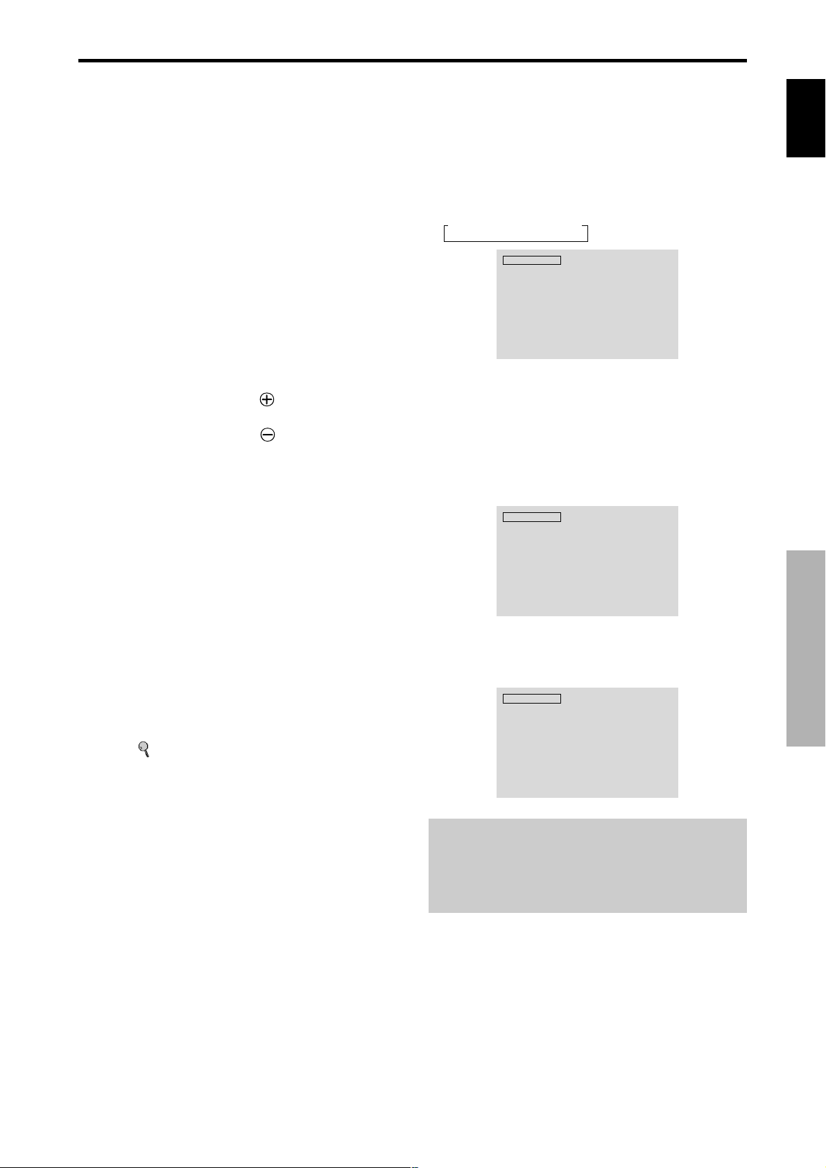
OFF TIMER
To set the off timer:
The off timer can be set to turn the power of f after 30, 60,
90 or 120 minutes.
1. Press the OFF TIMER button to start the timer at 30
minutes.
2. Press the OFF TIMER button to the desired time.
3. The timer starts when the menu turns off.
→ 30 → 60 → 90 → 120 → 0
OFF TIMER 30
To check the remaining time:
1. Once the off timer has been set, press the OFF TIMER
button once.
2. The remaining time is displayed, then turns off after a
few seconds.
3. When five minutes remain the remaining time appears
until it reaches zero.
OFF TIMER 28
To cancel the off timer:
1. Press the OFF TIMER button twice in a row.
2. The off timer is canceled.
OFF TIMER 0
Note:
After the power is turned off with the off timer ...
A slight current is still supplied to the monitor. When you
are leaving the room or do not plan to use the system for a
long period of time, turn off the power of the monitor.
English
Basic Operations
7
En
Page 13
WIDE Operations
English
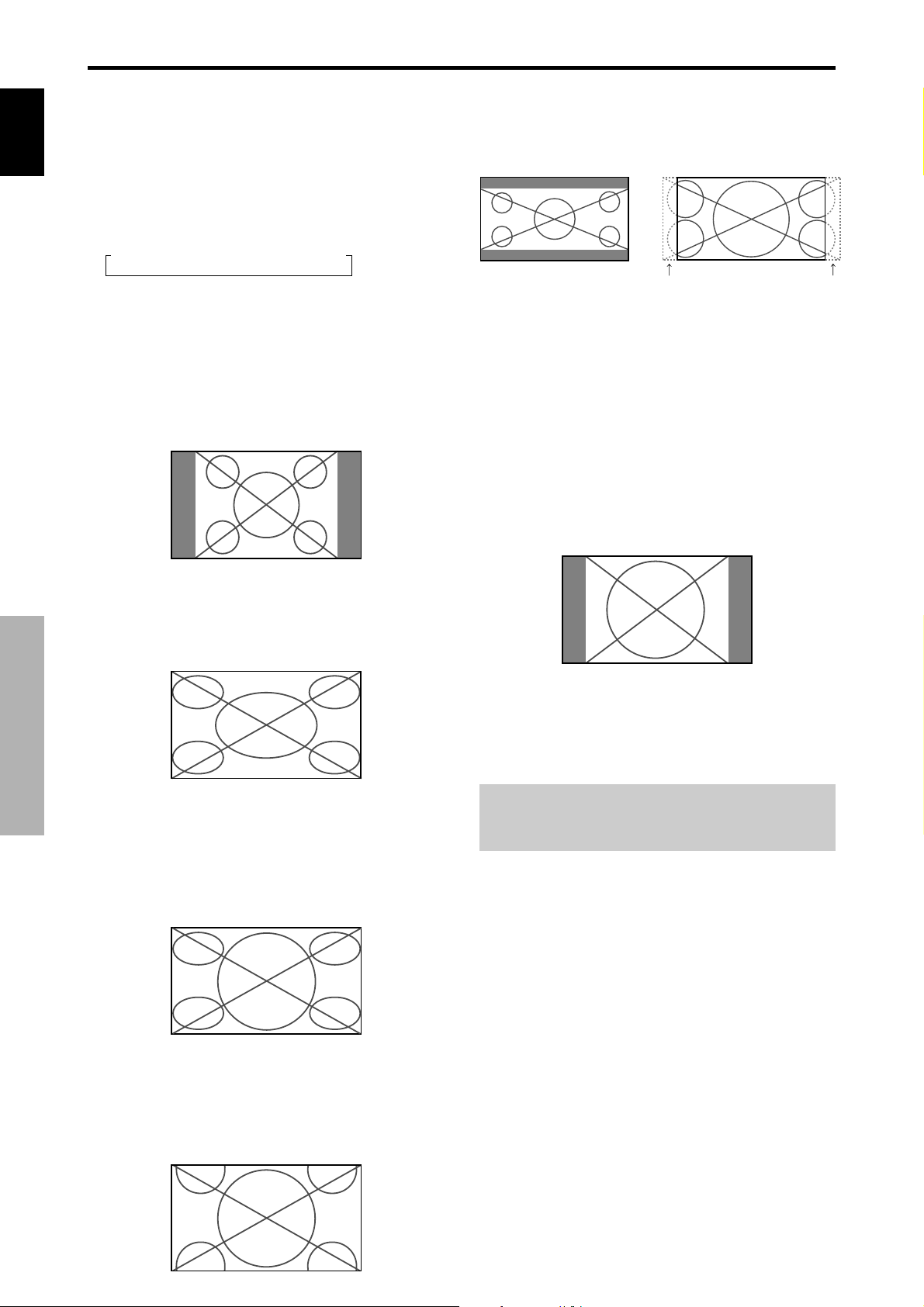
SCREEN SIZE Operation
With this function, you can select one of six screen sizes.
(manual)
When viewing videos or digital video discs
1. Press the SCREEN SIZE button on the remote control.
2. Within 3 seconds ...
Press the SCREEN SIZE button again.
The screen size switches as follows:
→ 4:3 → FULL → WIDE → ZOOM → 2.35:1 → 14:9
When a 720P or 1080I signal is input:
FULL ↔ 2.35:1
When displaying enhanced split screen:
4:3 ↔ FULL
The screen size is fixed to FULL when 720P or 1080I
is input.
4:3 size screen
The picture is expanded in the horizontal and vertical
direction, maintaining the original proportions.
* Use this for theater size (wide) movies, etc.
2.35:1 size screen
Original image
Information is lost on both sides.
The squeezed film image is expanded to fulfill the entire
screen at a ratio of 2.35:1. Black bands do not appear at
the top and bottom but information is lost on the left and
right margins.
• This feature is available when the input signal is video,
component (480I, 480P, 576I, 576P, 720P, 1080I) or
RGB (525P or 625P signal from a scan converter) or
HDMI (480I, 480P, 720P, 1080I, 576P).
* If black bands appear on the top and bottom in the full size
screen, select the 2.35:1 size screen to avoid phosphor burnin.
14:9 size screen
The normal size screen is displayed.
* The picture has the same size as video pictures with a 4 : 3
aspect ratio.
FULL size screen
WIDE Operations
The image is expanded in the horizontal direction.
* Images compressed in the horizontal direction (“squeezed
images”) are expanded in the horizontal direction and
displayed on the entire screen with correct linearity.
(Normal images are expanded in the horizontal direction.)
WIDE size screen
The image is displayed at a 14:9 aspect ratio.
* This feature is available when the input signal is video,
component (480I, 480P, 576I, 576P ) or RGB (525P or
625P signal from a scan converter) or HDMI (480I, 480P,
576P).
Note:
Do not allow the displayed in 4:3 mode for an extended
period. This can cause a phosphor burn-in.
8
En
The picture is expanded in the horizontal and vertical
directions at different ratios.
* Use this for watching normal video programs (4:3) with a
wide screen.
ZOOM size screen
Page 14
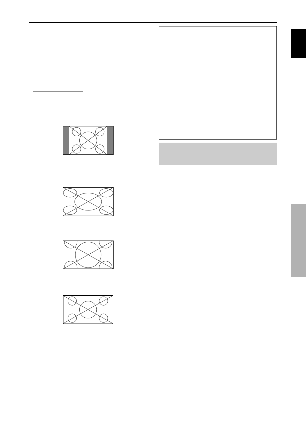
SCREEN SIZE Operation with
Computer Signals
Switch to the wide screen mode to expand the 4 : 3 image
to fill the entire screen.
1.Press the SCREEN SIZE button on the remote control.
2.Within 3 seconds ...
Press the SCREEN SIZE button again.
The screen size switches as follows:
→ 4:3 → FULL → ZOOM
When displaying enhanced split screen:
4:3 ↔ FULL
4:3 size screen (4:3 or SXGA 5:4)
The picture has the same size as the normal computer
image.
Information
Supported resolution
See page 27 for details on the display output of the
various VESA signal standards supported by the
monitor.
“D BY D”, a way of displaying pixels in a one-to-one
correspondence with input signals, can be switched only
when a 1280 dot x 768 line signal is input.
When 852 (848) dot 480 line wide VGA*
signals with a vertical frequency of 60 Hz and
horizontal frequency of 31.7 (31.0) kHz are input
Select an appropriate setting for RGB SELECT mode
referring to the“Table of Signals Supported” on page
27.
* “VGA ”, “SVGA” and “SXGA” are registered
trademarks of IBM, Inc. of the United States.
Note:
Do not allow the displayed in 4:3 mode for an extended
period. This can cause a phosphor burn-in.
English
FULL size screen
The image is expanded in the horizontal direction.
ZOOM size screen
When wide signals are input.
FULL size screen
WIDE Operations
9
En
Page 15
SPLIT SCREEN Operations
VIDEO1 PC1DSUB
AB
VIDEO1
PC1DSUB
BA
VIDEO1 PC1DSUB
AB
VIDEO1 PC1DSUB
AB
English
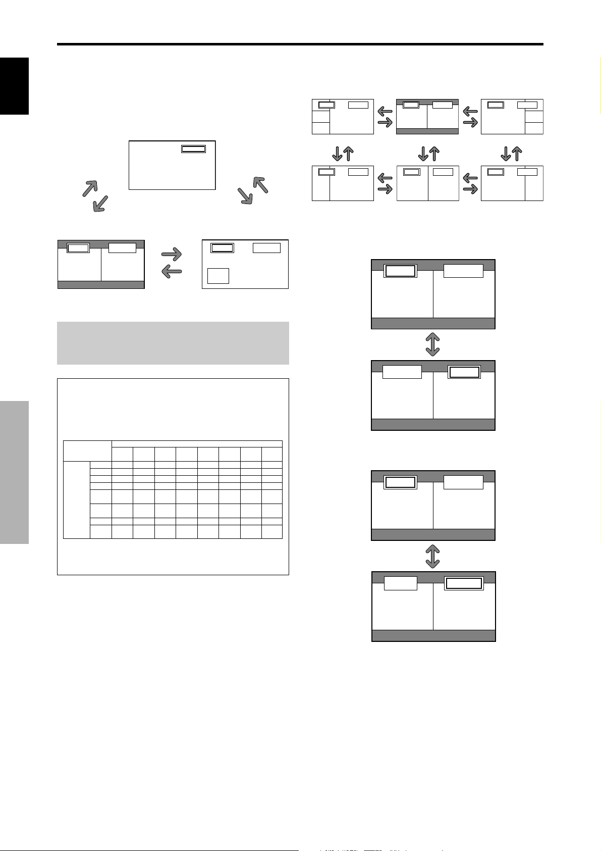
Showing a couple of pictures on the
screen at the same time
* A PC-input picture may not be displayed in these modes,
depending on the input signal specifications.
1. Press the button to select a screen mode from among
single mode, side-by-side, and picture-in-picture.
VIDEO1
SINGLE
button
SIDE BY SIDE
button
VIDEO1 PC1DSUB
AB
A
SIDE BY SIDE
button
P IN P
button
P IN P
button
VIDEO1
Sub
screen
Note:
Picture A and B on the above screen are not always of the
same height.
SINGLE
button
PC1DSUB
Main screen
Operations in the Side-by-side mode
B
button
B
To change the picture size, press the cursor or
button.
VIDEO1 PC2-BNC
A
B
Side-by-Side2-R Side-by-Side1 Side-by-Side2-L
button
VIDEO1 PC2-BNC
A
B
Side-by-Side4-R Side-by-Side3 Side-by-Side4-L
button
button
button
button
button
VIDEO1 PC2-BNC
AB
button
VIDEO1 PC2-BNC
AB
button
button
button
button
button
VIDEO1 PC2-BNC
A
button
VIDEO1 PC2-BNC
A
To swap the picture on the right and the left, press the
cursor
button.
button
Information
Split screen operations may not function depending on
the combination of input signals. In the table below,
“” means Yes, “” means No.
Pictures
VIDEO1
displayed on
VIDEO2
the left/sub
VIDEO3
screen
COMPONENT1
(Select2)
PC2
COMPONENT2
PC1
SPLIT SCREEN Operations
HDMI
SCART1-3
Split screen operations may not function
depending on the type of the PC signals.
VIDEO1
Pictures displayed on the right/main screen (Select1)
VIDEO3
COMPONENT1
VIDEO2
PC2
COMPONENT2
1,2:
3:
PC1
1,2:
3:
HDMI
SCART1-3
1,2:
3:
1,2:
3:
To make the desired picture active, press the ACTIVE
SELECT button.
ACTIVE SELECT
button
10
En
Page 16
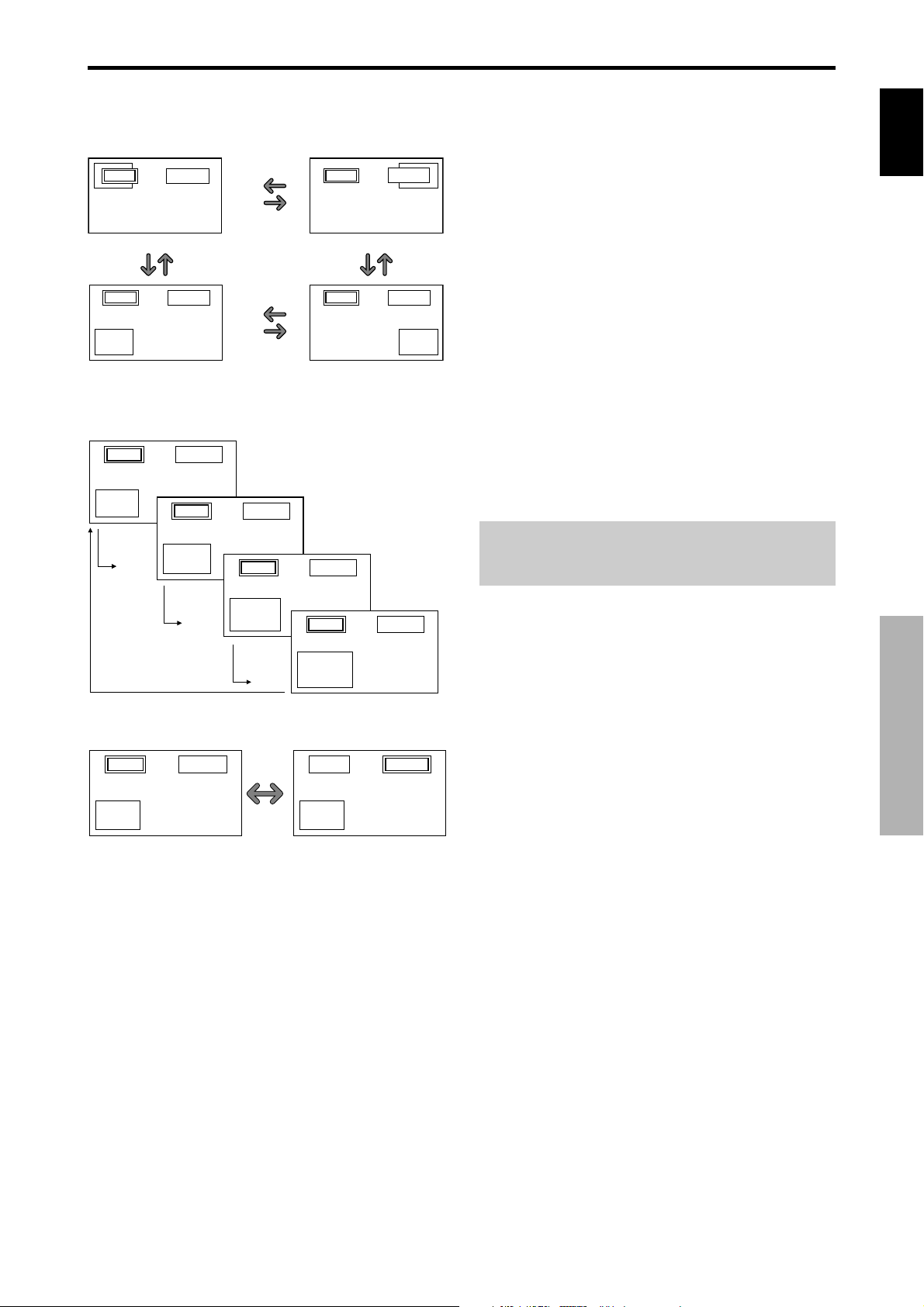
Operations in the Picture-in-picture mode
T o move the position of the sub screen, press the cursor
or button.
VIDEO1 PC2-BNC
A
B
Top Left
button
VIDEO1 PC2-BNC
A
Bottom Left Bottom Right
B
button
button
button
button
button
VIDEO1
button
VIDEO1 PC2-BNC
To change the size of the sub screen, press the
VIDEO1 PC1DSUB
B
Top Right
B
PC2-BNC
A
button
A
button.
B
A
VIDEO1 PC1DSUB
B
button
A
VIDEO1 PC1DSUB
Selecting the input signals to be displayed
1. Press the ACTIVE SELECT b utton to make the desired
picture active.
2. Press the PC1, VIDEO1, 2, 3, COMPONENT1, PC2/
English
COMPONENT2 or HDMI button to change the
selection of the input signal.
The INPUT/EXIT button on the monitor can also be
used to change the selection.
Zooming up pictures
1. Press the ACTIVE SELECT b utton to make the desired
picture active.
2. Use the ZOOM ( or ) button to enlage the picture.
For details, see “DIGITAL ZOOM” on page 7.
Adjusting the OSD controls
1. Press the ACTIVE SELECT b utton to make the desired
picture active.
2. Press the MENU/SET button to display the MAIN MENU.
3. Adjust the setting to your preference.
For details, see “OSD (On Screen Display) Controls”
on page 12.
Note:
During enhanced split screen, some functions of OSD
controls are not available.
B
button
A
VIDEO1 PC1DSUB
B
button
button
To make the desired picture active, press the ACTIVE
SELECT button.
VIDEO1 PC1DSUB
B
A
ACTIVE
SELECT
button
A
VIDEO1 PC1DSUB
B
A
SPLIT SCREEN Operations
11
En
Page 17
OSD (On Screen Display) Controls
English
Menu Operations
The following describes how to use the menus and the
selected items.
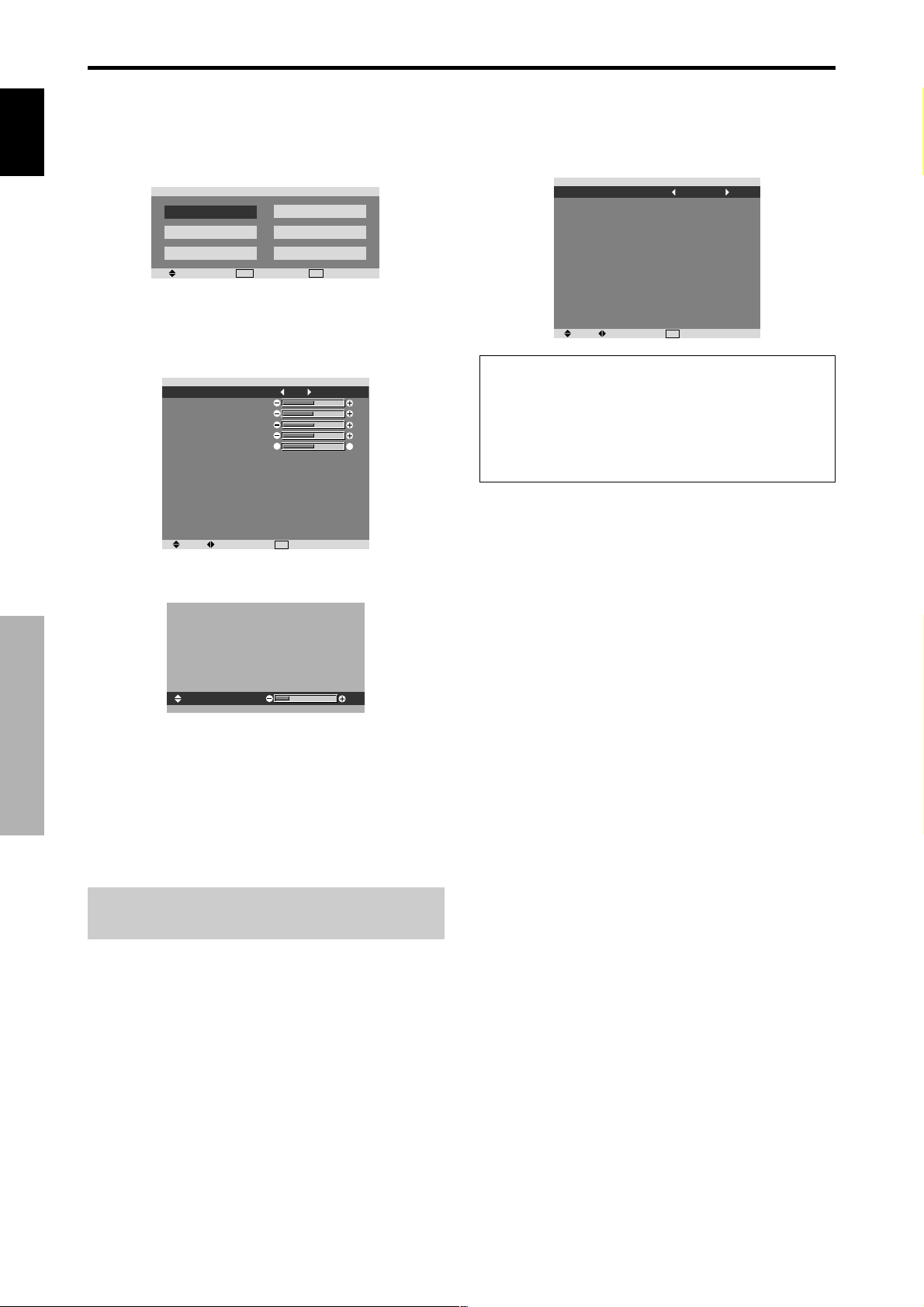
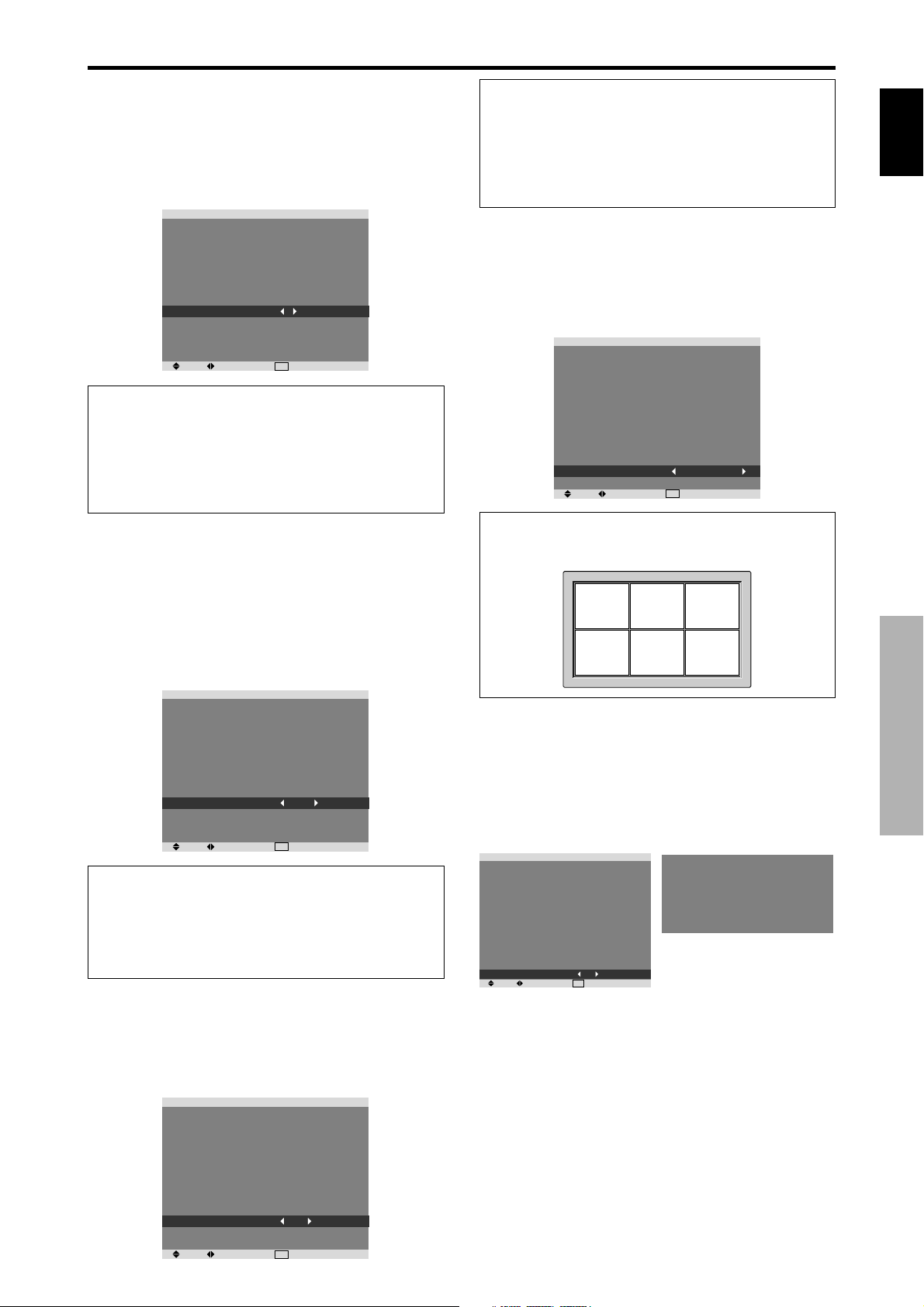
1. Press the MENU/SET button on the remote control to
display the MAIN MENU.
MAIN MENU
PICTURE
SOUND
SCREEN
SEL.
MENU
OK
2. Press the cursor buttons ▲ ▼ on the remote control to
highlight the menu you wish to enter.
3. Press the MENU/SET button on the remote control to
select a sub menu or item.
PICTURE MEMORY
CONTRAST
BRIGHTNESS
SHARPNESS
COLOR
TINT
DNR
COLOR TEMP.
GAMMA
LOW TONE
SET UP LEVEL
COLOR MGT
PURECINEMA
AV SELECTION
SEL. ADJ.
PICTURE
4. Adjust the level or change the setting of the selected item
by using the cursor buttons
SET UP
FUNCTION
SIGNAL INFO.
EXIT
EXIT
: OFF
R
: LOW
: MIDDLE
: 2.1
: AUTO
: 0
: ON
: DYNAMIC
EXIT
RETURN
G
on the remote control.
Setting the language for the menus
The menu display can be set to one of seven languages.
Example: Setting the menu display to “DEUTSCH”
On “LANGUA GE” of “SET UP” menu, select “DEUTSCH”.
LANGUAGE
BNC INPUT
D-SUB INPUT
HD SELECT
RGB SELECT
HDMI SET UP
COLOR SYSTEM
BACK GROUND
SIDE MASK
S1/S2
DISPLAY OSD
OSD ADJUST
ALL RESET
SEL. ADJ.
Information
Language settings
ENGLISH ........ English
DEUTSCH....... German
FRANÇAIS ...... French
ESPAÑOL ....... Spanish
SET UP
: DEUTSCH
: COMPONENT
: RGB
: 1080I
: AUTO
: COLOR1
: AUTO
: GRAY
: 3
: OFF
: ON
: TOP LEFT
: OFF
RETURN
EXIT
ITALIANO ........ Italian
SVENSKA .......Swedish
У ............Russian
CONTRAST
5. The adjustments or the settings that are stored in memory .
The change is stored until you change it again.
6. Repeat steps 2 – 5 to adjust an additional item, or press
the EXIT button on the remote control to return to the
OSD (On Screen Display) Controls
main menu.
* When adjusting using the bar at the bottom of the screen,
press the or button within 5 seconds. If not, the current
setting is set and the previous screen appears.
Note:
The main menu disappears by pressing the EXIT
button.
10
12
En
Page 18

Menu Tree
:Shaded areas indicate the default value.
←→
Main menu Sub menu Sub menu 2 Sub menu 3 RESET
PICTURE PICTURE MEMORY OFF/MEMORY1-6 YES 15
Main menu Sub menu Sub menu 2 Sub menu 3 RESET
SOUND BASS ←→ 0←13→26 YES 18
Main menu Sub menu Sub menu 2 Sub menu 3 RESET
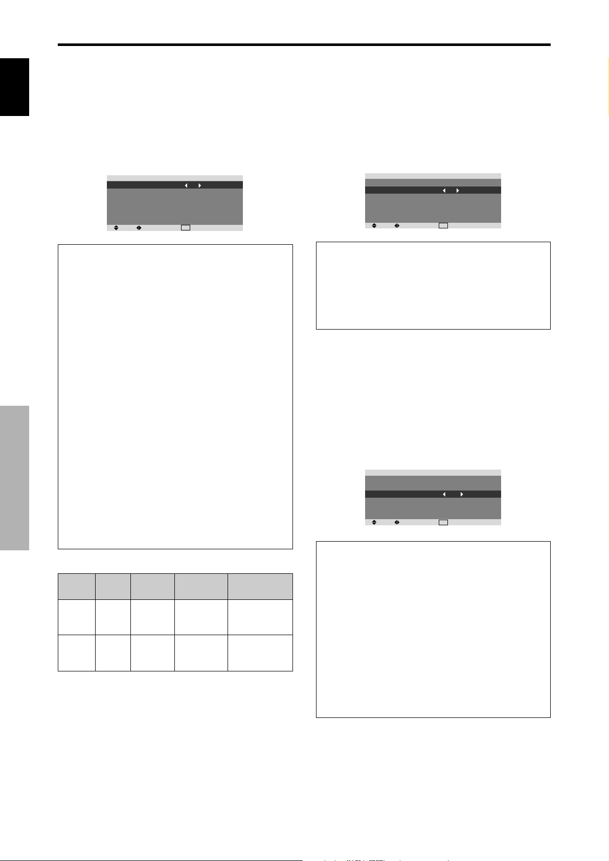
SCREEN SCREEN SIZE ZOOM/4:3/FULL/WIDE/14:9/2.35:1 NO 18
: Press the
or button to adjust.
REFERENCE
CONTRAST ←→ 0←52→72 YES 15
BRIGHTNESS ←→ 0←32→64 YES 15
SHARPNESS ←→ 0←16→32 YES 15
COLOR ←→ 0←32→64 YES 15
TINT R←→G 0←32→64 YES 15
DNR OFF/LOW/MID/HIGH YES 15
COLOR TEMP. LOW/MIDDLE LOW/MIDDLE/HIGH YES 16
WHITE BALANCE R.HIGH ←→ 0←40→70 YES 16
G.HIGH ←→ 0←40→70 YES 16
B.HIGH ←→ 0←40→70 YES 16
R.LOW ←→ 0←40→70 YES 16
G.LOW ←→ 0←40→70 YES 16
B.LOW ←→ 0←40→70 YES 16
GAMMA 2.1←2.2←2.3→2.4 YES 16
LOW TONE AUTO←→1←…→3 YES 16
SET UP LEVEL 0←→3.75←→7.5 YES 17
COLOR MGT RED Y←→M0←32→64 YES 17
PURECINEMA ON←→OFF YES 17
AV SELECTION DEFAULT/MOVIE1/MOVIE2/STANDARD/DYNAMIC YES 17
TREBLE ←→ 0←13→26 YES 18
BALANCE L←→R -22←0→+22 YES 18
AUDIO INPUT1 VIDEO 1-3 / COMPNT 1-2 / PC1DSUB / PC2-BNC YES 18
AUDIO INPUT2 VIDEO 1-3 / COMPNT 1-2 / PC1DSUB / PC2-BNC YES 18
AUDIO INPUT3 VIDEO 1-3 / COMPNT 1-2 / PC1DSUB / PC2-BNC YES 18
HDMI INPUT ON←→OFF YES 18
V.POSITION ←→ -64←0→+64 YES 18
H.POSITION ←→ -128←0→+127 YES 18
V.SIZE ←→ 0←→64 YES 18
H.SIZE ←→ 0←→64 YES 18
AUTO PICTURE ON←→OFF*
1
PHASE*
1
CLOCK*
RESET OFF←→ON YES 16
GREEN C←→Y0←32→64 YES 17
BLUE M←→C0←32→64 YES 17
YELLOW G←→R0←32→64 YES 17
MAGENTA R←→B0←32→64 YES 17
CYAN B←→G0←32→64 YES 17
RESET OFF←→ON YES 17
REFERENCE
REFERENCE
2
←→*20←→64 YES 18
←→*20←64→128 YES 18
NO 18
English
OSD (On Screen Display) Controls
Main menu Sub menu Sub menu 2 Sub menu 3 RESET
SET UP LANGUAGE ENGLISH/DEUTSCH/FRANÇAIS/ESPAÑOL/ITALIANO/SVENSKA/У NO 12
BNC INPUT RGB←→COMPONENT←→SCART1←→SCART2 YES 19
D-SUB INPUT RGB←→SCART3 YES 19
HD SELECT 1080I/1035I/540P NO 19
RGB SELECT AUTO/STILL/MOTION/WIDE1/WIDE2/WIDE3/WIDE4/DTV YES 19
HDMI SET UP COLOR1←→COLOR2 NO 20
COLOR SYSTEM AUTO/PAL/PAL-M/PAL-N/PAL 60/SECAM/4.43 NTSC/3.58NTSC NO 20
BACK GROUND BLACK/GRAY YES 20
SIDE MASK 0←…→3←…→15 YES 21
S1/S2 AUTO←→OFF YES 21
DISPLAY OSD ON←→OFF YES 21
OSD ADJUST TOP LEFT←→TOP CENTER←→TOP RIGHT←→BTM LEFT←→BTM CENTER←→BTM RIGHT YES 21
ALL RESET ON←→OFF —21
REFERENCE
13
En
Page 19

English
Main menu Sub menu Sub menu 2 Sub menu 3 RESET
FUNCTION POWER MGT. ON←→OFF YES 22
INPUT SKIP ON←→OFF YES 22
SUB. P DETECT AUTO←→OFF YES 22
ZOOM NAV OFF←→S BY S←→BTM LFT←→BTM RGT←→TOP RGT←→TOP LFT YES 23
PICTURE FREEZE OFF←→S BY S1←→S BY S2←→BTM LEFT←→BTM RIGHT←→TOP RIGHT←→TOP LEFT YES 23
LONG LIFE MANUAL/AUTO YES 23
ABL 100/75/50/25 YES 24
ORBITER OFF/AUTO1/AUTO2 YES 24
INVERSE/WHITE OFF/INVERSE/WHITE YES 24
SCREEN WIPER ON/OFF YES 24
SOFT FOCUS OFF/LEVEL1-4 YES 24
OSD ORBITER ON/OFF YES 25
OSD CONTRAST LOW/NORMAL YES 25
REFERENCE
Main menu Sub menu Sub menu 2 Sub menu 3 RESET
SIGNAL INFO. — 25
REFERENCE
*1 Only when A UTO PICTURE is OFF .
*2 PC only
Information
Restoring the factory default settings
Select “ALL RESET” under the SET UP menu. Note that this also restores other settings to the factory defaults.
OSD (On Screen Display) Controls
14
En
Page 20
Picture Settings Menu
Storing picture settings
This function allows you to store in memory the current
input signal and PICTURE menu settings and to recall
these settings when necessary.
There are six picture memories, and notes of up to 15
characters can be added to each.
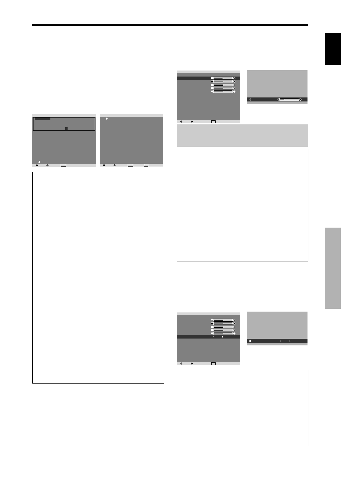
Example: Storing picture settings at MEMORY1
On “PICTURE MEMORY” of “PICTURE” menu, select
“MEMOR Y1”, then press the MENU/SET button.
The “PICTURE MEMOR Y” screen appears.
EXIT
RETURN
2/2
and
PICTURE MEMORY
MEMORY1 SET RESET
INPUT : COMPNT1
SIGNAL : 480P
NOTE : DVD/STAR WARS
MEMORY2
INPUT : —
SIGNAL : —
NOTE : —
MEMORY3
INPUT : —
SIGNAL : —
NOTE : —
NEXT PAGE
SEL. ADJ.
MENU
OK
1/2
PICTURE MEMORY
PREVIOUS PAGE
MEMORY4 SET RESET
INPUT : —
SIGNAL : —
NOTE : —
MEMORY5
INPUT : —
SIGNAL : —
NOTE : —
MEMORY6
INPUT : —
SIGNAL : —
NOTE : —
SEL. ADJ.
MENU
OK
Information
PICTURE MEMORY Settings
OFF: Picture memory not used.
MEMORY1 to 6: Picture memory with the specified
number used. Maximum memories are 6, not depending
on inputs.
Setting the memory
• Use the ▲ and ▼ button to select the desired memory
place, MEMORY1 to MEMORY6.
• Use the
and buttons to select “SET”, then press
the MENU/SET button.
• If necessary, input a note.
Resetting the memory
Use the ▲ and ▼ button to select the desired memory
place, MEMOR Y1 to MEMORY6, then use the
buttons to select “RESET”, and finally press the
MENU/SET button.
The memory is cleared, and “—” is displayed in the
“INPUT”, “SIGNAL” and “NOTE” columns.
Inputting notes
• Use the
and buttons to select “NOTE”, then press
the MENU/SET button.
• Input the note.
Use the ▲ and ▼ button to select the character.
Use the
and buttons to move the cursor.
Use the EXIT button to delete the character at the
cursor position.
• When you have finished inputting the note, press the
MENU/SET button.
Adjusting the picture
The contrast, brightness, sharpness, color and tint can be
adjusted as desired.
Example: Adjusting the contrast
On “CONTRAST” of “PICTURE” menu, adjust the contrast.
PICTURE MEMORY
CONTRAST
BRIGHTNESS
SHARPNESS
COLOR
TINT
DNR
COLOR TEMP.
GAMMA
LOW TONE
SET UP LEVEL
COLOR MGT
PURECINEMA
AV SELECTION
Note:
PICTURE
: OFF
R
: LOW
: MIDDLE
: 2.1
: AUTO
: 0
: ON
: DYNAMIC
EXIT
RETURNSEL. ADJ.
G
CONTRAST
If “CAN NOT ADJUST” appears ...
10
When trying to enter the PICTURE submenu, make sure
AV SELECTION is not set to DEFAULT.
Information
Picture adjustment screen
CONTRAST: Changes the picture’s white level.
BRIGHTNESS: Changes the picture’s black level.
SHARPNESS: Changes the picture’s sharpness.
Adjusts picture detail of VIDEO display.
COLOR: Changes the color density.
TINT: Changes the picture’s tint. Adjust for natural
colored skin, background, etc.
Adjusting the computer image
Only the contrast and brightness can be adjusted when
a computer signal is connected.
Restoring the factory default settings
Select “DEFAULT” under the “AV SELECTION”
settings.
Reducing noise in the picture
Use these settings if the picture has noise due to poor
reception or when playing video tapes on which the picture
quality is poor.
Example: Setting “HIGH”
On “DNR” of “PICTURE” menu, select “HIGH”.
PICTURE MEMORY
CONTRAST
BRIGHTNESS
SHARPNESS
COLOR
TINT
DNR
COLOR TEMP.
GAMMA
LOW TONE
SET UP LEVEL
COLOR MGT
PURECINEMA
AV SELECTION
PICTURE
: OFF
R
: LOW
: MIDDLE
: 2.1
: AUTO
: 0
: ON
: DYNAMIC
EXIT
RETURNSEL. ADJ.
G
DNR
: HIGH
Information
DNR
* “DNR” stands for Digital Noise Reduction.
* This function reduces noise in the picture.
Types of noise reduction
There are three types of noise reduction. Each has a
different level of noise reduction.
The effect increases stronger in the order of LOW, MID
and HIGH.
OFF: Turns the noise reduction function off.
English
OSD (On Screen Display) Controls
15
En
Page 21
English
Setting the color temperature
Use this procedure to set color tone produced by the plasma
display.
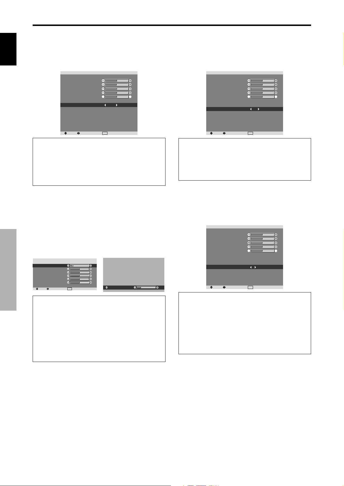
Example: Setting “HIGH”
On “COLOR TEMP . ” of “PICTURE” menu, select “HIGH”.
PICTURE MEMORY
CONTRAST
BRIGHTNESS
SHARPNESS
COLOR
TINT
DNR
COLOR TEMP.
GAMMA
LOW TONE
SET UP LEVEL
COLOR MGT
PURECINEMA
AV SELECTION
PICTURE
: OFF
R
: LOW
: HIGH
: 2.1
: AUTO
: 0
: ON
: DYNAMIC
EXIT
G
RETURNSEL. ADJ.
Changing the Gamma Curve
This feature adjusts the brightness of the midtone areas
while keeping shadows and highlights unchanged.
Example: Setting “2.3”
On “GAMMA” of “PICTURE” menu, select “2.3”.
PICTURE MEMORY
CONTRAST
BRIGHTNESS
SHARPNESS
COLOR
TINT
DNR
COLOR TEMP.
GAMMA
LOW TONE
SET UP LEVEL
COLOR MGT
PURECINEMA
AV SELECTION
PICTURE
: OFF
R
: LOW
: MIDDLE
: 2.3
: AUTO
: 0
: ON
: DYNAMIC
EXIT
G
RETURNSEL. ADJ.
Information
Setting the color temperature
LOW: Redder
MIDDLE LOW: Slightly red
MIDDLE: Standard (slightly bluer)
HIGH: Bluer
Adjusting the color to the desired level
Use this procedure to adjust the white balance for each
color temperature to achieve the desired color quality.
Example: Adjusting the “R.HIGH” of “HIGH” color
temperature
On “COLOR TEMP . ” of “PICTURE” menu, select “HIGH”,
then press the MENU/SET button.
The “WHITE BALANCE” screen appears.
On “R.HIGH”, adjust the white balance.
WHITE BALANCE
COLOR TEMP. HIGH
R.HIGH
G.HIGH
B.HIGH
R.LOW
G.LOW
B.LOW
RESET
SEL. ADJ.
OSD (On Screen Display) Controls
Information
Adjusting the white balance
: OFF
EXIT
RETURN
R/G/B HIGH: White balance adjustment for white lev el
R/G/B LOW: White balance adjustment for black le vel
RESET: Resets settings to the factory default values.
Use
and buttons to select “ON”, then press the
MENU/SET button.
Restoring the factory default settings
Select “RESET” under the WHITE B ALANCE menu.
R.HIGH
Information
GAMMA settings
The picture becomes darker as the number increases
(in the sequence of 2.1, 2.2, 2.3, 2.4).
* These values are approximate.
Making the Low Tone adjustments
This feature allows more detailed tone to be reproduced
especially in the dark area.
Example: Setting “2”
On “LOW TONE” of “PICTURE” menu, select “2”.
PICTURE MEMORY
CONTRAST
BRIGHTNESS
SHARPNESS
COLOR
TINT
DNR
COLOR TEMP.
GAMMA
LOW TONE
SET UP LEVEL
COLOR MGT
PURECINEMA
20
AV SELECTION
PICTURE
: OFF
R
: LOW
: MIDDLE
: 2.1
: 2
: 0
: ON
: DYNAMIC
EXIT
G
RETURNSEL. ADJ.
Information
LOW TONE settings
AUTO: Will automatically appraise the picture and
make adjustments.
1: Will apply the dither method suitable for still pictures.
2: Will apply the dither method suitable for motion
pictures.
3: Will apply the error diffusion method.
16
En
Page 22

Adjusting the pedestal level (black level)
This feature adjusts the video black level in a video image.
Example: Setting “3.75”
On “SET UP LEVEL” of “PICTURE” menu, select “3.75”.
PICTURE MEMORY
CONTRAST
BRIGHTNESS
SHARPNESS
COLOR
TINT
DNR
COLOR TEMP.
GAMMA
LOW TONE
SET UP LEVEL
COLOR MGT
PURECINEMA
AV SELECTION
PICTURE
: OFF
R
: LOW
: MIDDLE
: 2.1
: AUTO
: 3.75
: ON
: DYNAMIC
EXIT
G
RETURNSEL. ADJ.
Information
SET UP LEVEL settings
0: Normal status
3.75: 3.75% lower than normal
7.5: 7.5% lower than normal
Adjusting the colors
Use this procedure to adjust hue and color density for red,
green, blue, yellow, magenta and cyan.
You can accentuate the green color of trees, the blue of
the sky, etc.
Example: Adjusting the color management for blue
On “PICTURE” menu, select “COLOR MGT”, then press
the MENU/SET button.
The “COLOR MGT” screen appears.
On “BLUE” of “COLOR MGT”, adjust the color
management.
RED
GREEN
BLUE
YELLOW
MAGENTA
CYAN
RESET
SEL. ADJ.
COLOR MGT
Y
C
M
G
R
B
: OFF
EXIT
RETURN
M
Y
C
R
B
G
Information
COLOR MGT settings
RED: Makes red’s adjustment
GREEN: Makes green’s adjustment
BLUE: Makes blue’s adjustment
YELLOW: Makes yellow’s adjustment
MAGENTA: Makes magenta’s adjustment
CYAN: Makes cyan’s adjustment
RESET: Resets settings to the factory default value.
and buttons to select “ON”, then press the
Use
MENU/SET button.
Setting the picture to suit the movie
The film image is automatically discriminated and
projected in an image mode suited to the picture.
[NTSC, PAL, PAL60, 480I (60Hz), 525I (60Hz), 576I
(50Hz), 625I (50Hz), 1035I (60Hz), 1080I (60Hz) only]
Example: Setting the “PURECINEMA” to “OFF”
On “PURECINEMA” of “PICTURE” menu, select “OFF”.
PICTURE MEMORY
CONTRAST
BRIGHTNESS
SHARPNESS
COLOR
TINT
DNR
COLOR TEMP.
GAMMA
LOW TONE
SET UP LEVEL
COLOR MGT
PURECINEMA
AV SELECTION
PICTURE
: OFF
R
: LOW
: MIDDLE
: 2.1
: AUTO
: 0
: OFF
: DYNAMIC
EXIT
G
RETURNSEL. ADJ.
Information
PURECINEMA
ON: Automatic discrimination of the image and
projection in PURECINEMA.
OFF: PURECINEMA does not function.
Setting the picture modes according to the
brightness of the room
There are four picture modes that can be used effectively
according to the environment in which you are viewing
the display.
Example: Setting the “MOVIE1” mode
On “AV SELECTION” of “PICTURE” menu, select
“MOVIE1”.
PICTURE MEMORY
CONTRAST
BRIGHTNESS
SHARPNESS
COLOR
TINT
DNR
COLOR TEMP.
GAMMA
LOW TONE
SET UP LEVEL
COLOR MGT
PURECINEMA
AV SELECTION
PICTURE
: OFF
R
: LOW
: MIDDLE
: 2.1
: AUTO
: 0
: ON
: DYNAMIC
EXIT
RETURNSEL. ADJ.
G
AV SELECTION
: MOVIE1
Information
Types of AV SELECTION
MOVIE1, 2: Set this mode when watching video in a dark
room.
This mode provides darker , finer pictures, lik e the screen
in movie theaters.
For a darker image, select MO VIE2.
STANDARD: Set this mode when watching video in a
bright room.
This mode provides pictures with distinct differences
between light and dark sections.
DYNAMIC: This mode provides brighter pictures than
STANDARD.
DEFAULT: Use this to reset the picture to the factory
default settings.
STANDARD is the default setting when PC signal is
input.
English
OSD (On Screen Display) Controls
17
En
Page 23
SOUND Settings Menu
Adjusting the treble, bass and left/right
balance and audio input select
English
OSD (On Screen Display) Controls
The treble, bass and left/right balance can be adjusted to
suit your tastes.
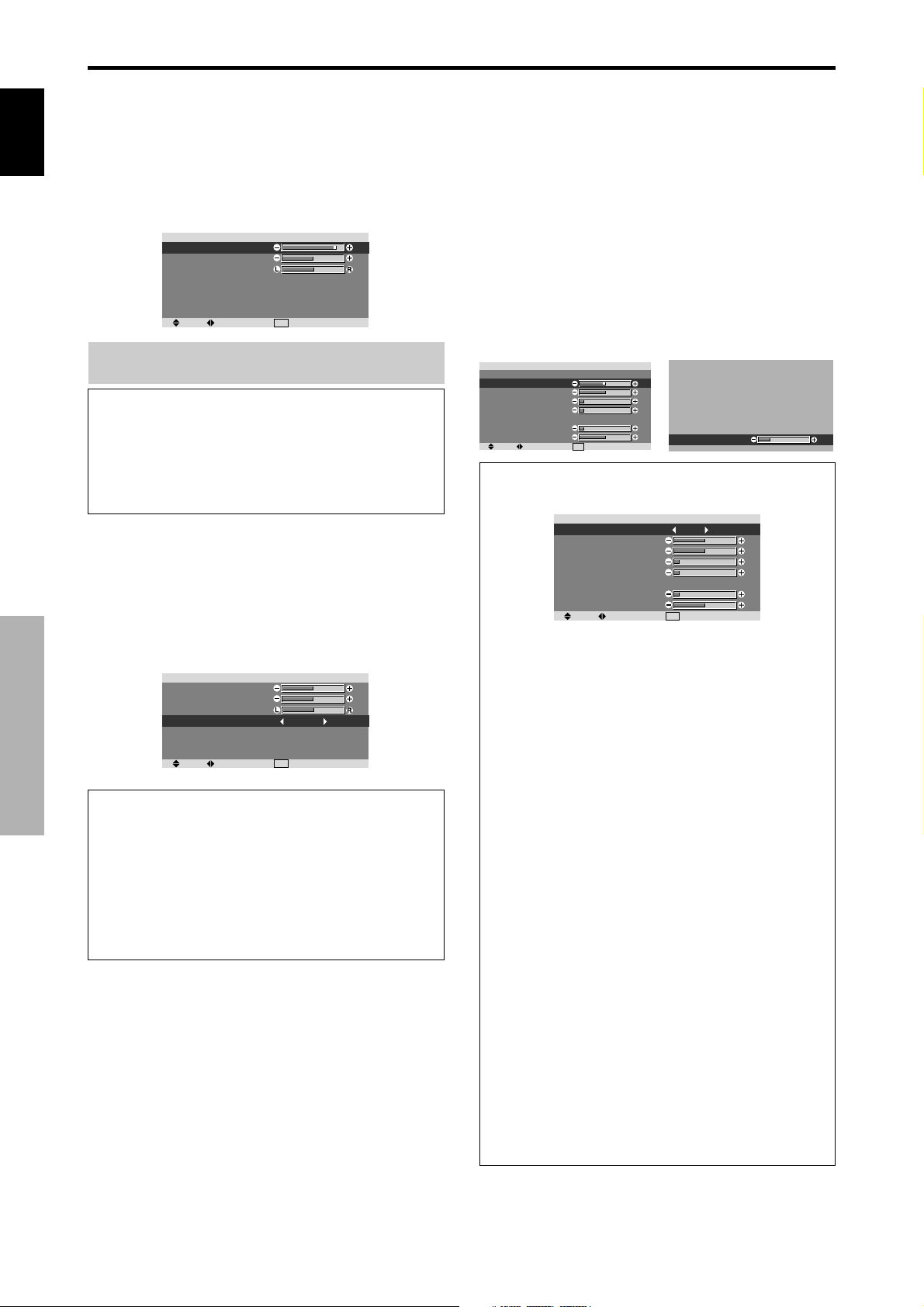
Example: Adjusting the bass
On “BASS” of “SOUND” menu, adjust the bass.
BASS
TREBLE
BALANCE
AUDIO INPUT1
AUDIO INPUT2
AUDIO INPUT3
HDMI INPUT
SEL. ADJ.
Note :
If “CAN NOT ADJUST” appears...
Set “AUDIO INPUT” on the SOUND menu correctly.
Information
SOUND settings menu
BASS: Controls the level of low frequency sound.
TREBLE: Controls the level of high frequency sound.
BALANCE: Controls the balance of the left and right
channels.
Setting the allocation of the audio connectors
Setting the AUDIO 1, 2, and 3 connectors to the desired
input.
Example: Setting “AUDIO INPUT1” to “VIDEO 2”
On “AUDIO INPUT1” of “SOUND” menu, select
“VIDEO2”.
The available sources depend on the settings of input.
BASS
TREBLE
BALANCE
AUDIO INPUT1
AUDIO INPUT2
AUDIO INPUT3
HDMI INPUT
SEL. ADJ.
Information
AUDIO INPUT
A single audio input cannot be selected as the audio
channel for more than one input terminal.
HDMI INPUT
ON: Enables the digital audio input signal transmitted
via the HDMI terminal.
OFF: Disables the digital audio input signal.
SOUND
SOUND
: VIDEO1
: COMPNT1
: PC1DSUB
: ON
RETURN
EXIT
: VIDEO2
: COMPNT1
: PC1DSUB
: ON
RETURN
EXIT
SCREEN Settings Menu
Adjusting the Position, Size, PHASE, CLOCK
The position of the image can be adjusted and flickering
of the image can be corrected.
Example: Adjusting the vertical position in the normal
mode
On “V.POSITION” of “SCREEN” menu, adjust the position.
The mode switches as follows each time the
pressed:
4:3 ↔ FULL
* The mode can also be switched by pressing the SCREEN
SIZE button on the remote control.
* The settings on the SCREEN menu are not preset at the
factory .
SCREEN SIZE
V.POSITION
H.POSITION
V.SIZE
H.SIZE
AUTO PICTURE
PHASE
CLOCK
SEL. ADJ.
SCREEN
: 4:3
: OFF
RETURN
EXIT
V.POSITION
Information
When “AUTO PICTURE” is “OFF”
SCREEN SIZE
V.POSITION
H.POSITION
V.SIZE
H.SIZE
AUTO PICTURE
PHASE
CLOCK
SEL. ADJ.
SCREEN
:
FULL
: OFF
RETURN
EXIT
When Auto Picture is of f, the PHASE and the CLOCK
items are displayed so that you can adjust them.
Adjusting the Auto Picture
ON: The CLOCK, PHASE and Position adjustments
are made automatically.
Not available for digital ZOOM.
OFF: The CLOCK, PHASE and Position adjustments
are made manually.
* If PHASE can’t be adjusted, set Auto Picture to OFF
and adjust manually.
Adjusting the position of the image
V.POSITION: Adjusts the vertical position of the
image.
H.POSITION: Adjusts the horizontal position of the
image.
V.SIZE: Adjusts the v ertical size of the image. (Except
for WIDE mode)
H.SIZE: Adjusts the horizontal size of the image.
(Except for WIDE mode)
PHASE*: Adjusts for flickering.
CLOCK*: Adjusts for striped patterns on the image.
* The CLOCK and PHASE features are available only
when the “Auto Picture” is off.
* The AUTO PICTURE, PHASE and CLOCK are
available only for RGB signals.
But, these features are not available for moving pictures
on RGB, VIDEO or COMPONENT.
or button is
-30
18
En
Page 24

SET UP Settings Menu
Setting the PC2/COMPONENT2 connectors
Select whether to set the PC2/COMPONENT2 input to
RGB and component or SCART1,2.
Example: Set the BNC INPUT mode to “RGB”
On “BNC INPUT” of “SET UP” menu, select “RGB”.
LANGUAGE
BNC INPUT
D-SUB INPUT
HD SELECT
RGB SELECT
HDMI SET UP
COLOR SYSTEM
BACK GROUND
SIDE MASK
S1/S2
DISPLAY OSD
OSD ADJUST
ALL RESET
SEL. ADJ.
Information
BNC INPUT Settings
RGB: Use the 5BNC terminals for HD, VD and RGB
signals.
COMPONENT: Use the 3BNC terminals for
component signals.
SCART1: Use the 4BNC terminals for RGB with
composite sync. See page 5.
SCART2: Use the 3BNC terminals for RGB and the
VIDEO1 terminal for composite sync. See page 5.
Setting the PC1 connector
Select one of the signals being transmitted to the PC1
terminal.
Example: Set the D-SUB INPUT mode to “SCART3”
On “D-SUB INPUT” of “SET UP” menu, select “SCART3”.
LANGUAGE
BNC INPUT
D-SUB INPUT
HD SELECT
RGB SELECT
HDMI SET UP
COLOR SYSTEM
BACK GROUND
SIDE MASK
S1/S2
DISPLAY OSD
OSD ADJUST
ALL RESET
SEL. ADJ.
Information
D-SUB INPUT Settings
RGB: Use the D-SUB terminal for RGB signals.
SCART3: Use the D-SUB terminal for RGB signal fed
from SCART. See page 5.
SET UP
: ENGLISH
: RGB
: RGB
: 1080I
: AUTO
: COLOR1
: AUTO
: GRAY
: 3
: OFF
: ON
: TOP LEFT
: OFF
EXIT
SET UP
: ENGLISH
: COMPONENT
: SCART3
: 1080I
: AUTO
: COLOR1
: AUTO
: GRAY
: 3
: OFF
: ON
: TOP LEFT
: OFF
EXIT
RETURN
RETURN
Setting high definition images to the suitable
screen size
Use this procedure to set whether the number of vertical
lines of the input high definition image is 1080I or 1035I
or 540P.
Example: Setting the “HD SELECT” mode to “1035I”
On “HD SELECT” of “SET UP” menu, select “1035I”.
LANGUAGE
BNC INPUT
D-SUB INPUT
HD SELECT
RGB SELECT
HDMI SET UP
COLOR SYSTEM
BACK GROUND
SIDE MASK
S1/S2
DISPLAY OSD
OSD ADJUST
ALL RESET
SEL. ADJ.
SET UP
: ENGLISH
: COMPONENT
: RGB
: 1035I
: AUTO
: COLOR1
: AUTO
: GRAY
: 3
: OFF
: ON
: TOP LEFT
: OFF
EXIT
RETURN
Information
HD SELECT modes
These 3 modes are not displayed in correct image
automatically.
1080I: Standard digital broadcasts
1035I: Japanese “High Vision” signal format
540P: Special Digital broadcasts (for example :
DTC100)
Setting a computer image to the correct RGB
select screen
With the computer image, select the RGB Select mode
for a moving image such as (video) mode, wide mode or
digital broadcast.
Example: Setting the “RGB SELECT” mode to
“MOTION ”
On “RGB SELECT” of “SET UP” menu, select “MOTION”.
LANGUAGE
BNC INPUT
D-SUB INPUT
HD SELECT
RGB SELECT
HDMI SET UP
COLOR SYSTEM
BACK GROUND
SIDE MASK
S1/S2
DISPLAY OSD
OSD ADJUST
ALL RESET
SEL. ADJ.
SET UP
: ENGLISH
: COMPONENT
: RGB
: 1080I
: MOTION
1024768
: AUTO
: GRAY
: 3
: OFF
: ON
: TOP LEFT
: OFF
EXIT
RETURN
English
OSD (On Screen Display) Controls
19
En
Page 25

Information
RGB SELECT modes
English
One of these 8 modes must be selected in order to
display the following signals correctly.
AUTO: Select the suitable mode for the specifications
of input signals as listed in the table “Computer input
signals supported by this system” on page 27.
STILL: To display VESA standard signals. (Use this
mode for a still image from a computer.)
MOTION: The video signal (from a scan converter)
will be converted to RGB signals to make the picture
more easily viewable. (Use this mode for a motion
image from a computer.)
WIDE1: When an 852 dot 480 line signal with a
horizontal frequency of 31.7kHz is input, the image may
be compressed horizontally. To prevent this, set RGB
SELECT to WIDE1.
WIDE2: When an 848 dot 480 line signal with a
horizontal frequency of 31.0 kHz is input, the image
may be compressed horizontally. To prevent this, set
RGB SELECT to WIDE2.
WIDE3: When an 1920 dot 1200 line signal with a
horizontal frequency of 74.0 kHz is input, the image
may be compressed horizontally. To prevent this, set
RGB SELECT to WIDE3.
WIDE4: When an 1280 dot 768 line signal with a
horizontal frequency of 59.8 kHz or an 1680 dot1050
line signal with a horizontal frequency of 60 kHz is
input, the image may be compressed horizontally. To
prevent this, set RGB SELECT to WIDE4.
DTV: Set this mode when watching digital broadcasting
(480P).
See page 27 for the details of the above settings.
Setting the black level for HDMI signal
Set the black level for the signal transmitted via the HDMI
terminal.
Example: Setting “COLOR2”
OSD (On Screen Display) Controls
On “HDMI SET UP” of “SET UP” menu, select
“COLOR2”.
LANGUAGE
BNC INPUT
D-SUB INPUT
HD SELECT
RGB SELECT
HDMI SET UP
COLOR SYSTEM
BACK GROUND
SIDE MASK
S1/S2
DISPLAY OSD
OSD ADJUST
ALL RESET
SEL. ADJ.
Information
HDMI SET UP settings
COLOR1: When connected to the SET TOP BOX,
DVD etc. Change “COLOR1” into “COLOR2” if the
black level appears gray.
COLOR2: Darker black level (real black).
SET UP
: ENGLISH
: COMPONENT
: RGB
: 1080I
: AUTO
: COLOR2
: AUTO
: GRAY
: 3
: OFF
: ON
: TOP LEFT
: OFF
EXIT
RETURN
Setting the video signal format
Use these operations to set the color systems of composite
video signals or Y/C input signals.
Example: Setting the color system to “3.58 NTSC”
On “COLOR SYSTEM” of “SET UP” menu, select
“3.58NTSC”.
LANGUAGE
BNC INPUT
D-SUB INPUT
HD SELECT
RGB SELECT
HDMI SET UP
COLOR SYSTEM
BACK GROUND
SIDE MASK
S1/S2
DISPLAY OSD
OSD ADJUST
ALL RESET
SEL. ADJ.
SET UP
: ENGLISH
: COMPONENT
: RGB
: 1080I
: AUTO
: COLOR1
: 3.58NTSC
: GRAY
: 3
: OFF
: ON
: TOP LEFT
: OFF
EXIT
RETURN
Information
Video signal formats
Different countries use different formats for video signals.
Set to the color system used in your current country .
AUTO: The color systems are automatically identified
and the format is set accordingly.
PAL: This is the standard format used mainly in the
United Kingdom and Germany.
SECAM: This is the standard format used mainly in
France and Russia.
4.43 NTSC, PAL60: This format is used for videos in
countries using PAL and SECAM video signals.
3.58 NTSC: This is the standard format used mainly
in the United States and Japan.
PAL-M: This is the standard format used mainly in
Brazil.
PAL-N: This is the standard format used mainly in
Argentina.
Setting the background color when no signal
is being input
The color displayed on the background when there is no
signal can be set to gray.
Example: Setting “BACK GROUND” to “BLACK”
On “BACK GROUND” of “SET UP” menu, select
“BLACK”.
LANGUAGE
BNC INPUT
D-SUB INPUT
HD SELECT
RGB SELECT
HDMI SET UP
COLOR SYSTEM
BACK GROUND
SIDE MASK
S1/S2
DISPLAY OSD
OSD ADJUST
ALL RESET
SEL. ADJ.
SET UP
: ENGLISH
: COMPONENT
: RGB
: 1080I
: AUTO
: COLOR1
: AUTO
: BLACK
: 3
: OFF
: ON
: TOP LEFT
: OFF
EXIT
RETURN
Information
BACK GROUND Settings
BLACK: Sets the background color to black.
GRAY: Sets the background color to gray.
Setting this makes it easier to see that there is no signal.
20
En
Page 26
Setting the gray level for the SIDE MASK
Use this procedure to set the gray level for the parts on the
screen on which nothing is displayed when the screen is
set to the 4:3 size and D BY D size.
Example: Setting “SIDE MASK” to “5”
On “SIDE MASK” of “SET UP” menu, select “5”.
LANGUAGE
BNC INPUT
D-SUB INPUT
HD SELECT
RGB SELECT
HDMI SET UP
COLOR SYSTEM
BACK GROUND
SIDE MASK
S1/S2
DISPLAY OSD
OSD ADJUST
ALL RESET
SEL. ADJ.
SET UP
: ENGLISH
: COMPONENT
: RGB
: 1080I
: AUTO
: COLOR1
: AUTO
: GRAY
: 5
: OFF
: ON
: TOP LEFT
: OFF
EXIT
RETURN
Information
SIDE MASK settings
This adjusts the brightness of the black (the gray level)
for the sides of the screen.
The standard is 0 (black). The level can be adjusted
from 0 to 15. The factory setting is 3 (dark gray).
Information
DISPLAY OSD settings
ON: The informations on screen size, volume control,
etc. will be shown.
OFF: The informations on screen size, volume control,
etc. will not be shown.
Setting the position of the menu
Adjusts the position of the menu when it appears on the
screen.
Example: Set the position to “TOP CENTER”
On “OSD ADJ.” of “SET UP” menu, select “TOP CENTER”.
LANGUAGE
BNC INPUT
D-SUB INPUT
HD SELECT
RGB SELECT
HDMI SET UP
COLOR SYSTEM
BACK GROUND
SIDE MASK
S1/S2
DISPLAY OSD
OSD ADJUST
ALL RESET
SEL. ADJ.
SET UP
: ENGLISH
: COMPONENT
: RGB
: 1080I
: AUTO
: COLOR1
: AUTO
: GRAY
: 3
: OFF
: ON
: TOP CENTER
: OFF
EXIT
RETURN
English
Setting the screen size for S1/S2 video input
If the S-video signal contains screen size information, the
image will be automatically adjusted to fit the screen when
this S1/S2 is set to AUTO.
This feature is available only when an S-video signal is
input via the VIDEO3 terminal.
Example: Setting “S1/S2” to “AUTO”
On “S1/S2” of “SET UP” menu, select “AUTO”.
LANGUAGE
BNC INPUT
D-SUB INPUT
HD SELECT
RGB SELECT
HDMI SET UP
COLOR SYSTEM
BACK GROUND
SIDE MASK
S1/S2
DISPLAY OSD
OSD ADJUST
ALL RESET
SEL. ADJ.
SET UP
: ENGLISH
: COMPONENT
: RGB
: 1080I
: AUTO
: COLOR1
: AUTO
: GRAY
: 3
: AUTO
: ON
: TOP LEFT
: OFF
EXIT
RETURN
Information
S1/S2 settings
AUTO: Adjusts the screen size automatically according
to the S1/S2 video signal.
OFF: Turns the S1/S2 function off.
Turning on/off the information display
When this is set to OFF, the information will not be
displayed even if you press the DISPLAY button.
Example: Turning the DISPLAY OSD off
On “DISPLAY OSD” of “SET UP” menu, select “OFF”.
LANGUAGE
BNC INPUT
D-SUB INPUT
HD SELECT
RGB SELECT
HDMI SET UP
COLOR SYSTEM
BACK GROUND
SIDE MASK
S1/S2
DISPLAY OSD
OSD ADJUST
ALL RESET
SEL. ADJ.
SET UP
: ENGLISH
: COMPONENT
: RGB
: 1080I
: AUTO
: COLOR1
: AUTO
: GRAY
: 3
: OFF
: OFF
: TOP LEFT
: OFF
EXIT
RETURN
Information
OSD ADJUST settings
TOP
LEFT
BTM
LEFT
TOP
CENTER
BTM
CENTER
TOP
RIGHT
BTM
RIGHT
Resetting to the default values
Use these operations to restore all the settings (PICTURE,
SOUND, SCREEN, SET UP, etc) to the factory default
values.
Refer to page 13 for items to be reset.
On “ALL RESET” of “SET UP” menu, select “ON”, then
press the MENU/SET button.
LANGUAGE
BNC INPUT
D-SUB INPUT
HD SELECT
RGB SELECT
HDMI SET UP
COLOR SYSTEM
BACK GROUND
SIDE MASK
S1/S2
DISPLAY OSD
OSD ADJUST
ALL RESET
SEL. ADJ.
SET UP
: ENGLISH
: COMPONENT
: RGB
: 1080I
: AUTO
: COLOR1
: AUTO
: GRAY
: 3
: OFF
: ON
: TOP LEFT
: ON
EXIT
RETURN
ALL RESET
SETTING NOW
When the “SETTING NOW” screen disappears, then all the
settings are restored to the default values.
OSD (On Screen Display) Controls
21
En
Page 27
English
Function Settings Menu
Setting the power management for computer
images
This energy-saving (power management) function
automatically reduces the monitor’s power consumption
if no operation is performed for a certain amount of time.
Example:
On “POWER MGT.” of “FUNCTION” menu, select “ON”.
Turning the power management function on
Setting the Input Skip
When this is ON, signals which are not present will be
skipped over and only pictures whose signals are being
transmitted will be displayed.
This setting is valid only for the INPUT/EXIT button on
the unit.
Example: Set to “ON”
On “INPUT SKIP” of “FUNCTION” menu, select “ON”.
POWER MGT.
INPUT SKIP
SUB. P DETECT
ZOOM NAV
PICTURE FREEZE
LONG LIFE
SEL. ADJ.
Information
Power management function
* The power management function automatically reduces
the monitor’s power consumption if the computer’s
keyboard or mouse is not operated for a certain amount
of time. This function can be used when using the
monitor with a computer.
* If the computer’s power is not turned on or if the
computer and selector tuner are not properly connected,
the system is set to the off state.
* For instructions on using the computer’s power
management function, refer to the computer’s operating
instructions.
Power management settings
ON: In this mode the power management function is
turned on.
OFF: In this mode the power management function is
turned off.
Power management function and STANDBY/
ON indicator
The STANDBY/ON indicator indicates the status of
the power management function. See below for
OSD (On Screen Display) Controls
indicator status and description.
STANDBY/ON indicator
Power
management
mode
On
Off
STANDBY/
ON
indicator
Green
Red
Power
management
operating status
Not activated.
Activated.
FUNCTION
: ON
: OFF
: AUTO
: BTM LEFT
: S BY S1
: MANUAL
EXIT
Description
Horizontal and vertical
synchronizing signals
are present from the
computer.
Horizontal and/or
vertical synchronizing
signals are not sent
from the computer.
RETURN
Turning the picture
back on
Picture already on.
Operate the keyboard or
mouse. The picture
reappears.
POWER MGT.
INPUT SKIP
SUB. P DETECT
ZOOM NAV
PICTURE FREEZE
LONG LIFE
SEL. ADJ.
FUNCTION
: OFF
: ON
: AUTO
: BTM LEFT
: S BY S1
: MANUAL
EXIT
RETURN
Information
INPUT SKIP settings
OFF: Regardless of the presence of the signal, scan
and display all signals.
ON: If no input signal is present, skip that signal.
* “SETTING NOW” will appear during the input search.
Erasing the sub screen image when there is
no input signal
This function automatically erases the black frame of the
sub screen when there is no sub screen input signal.
This feature is available only when the picuture-in-picuture
mode is selected.
Example: Set to “OFF”
On “SUB. P DETECT” of “FUNCTION” menu, select
“OFF”.
POWER MGT.
INPUT SKIP
SUB. P DETECT
ZOOM NAV
PICTURE FREEZE
LONG LIFE
SEL. ADJ.
FUNCTION
: OFF
: OFF
: OFF
: BTM LEFT
: S BY S1
: MANUAL
EXIT
RETURN
Information
SUB. P DETECT Function
* The sub screen disappears when the input signal is lost.
* Loss of the input signal means a condition in which the
video signal and the sync signal are not present.
* Under conditions in which the sub screen has
disappeared, the ZOOM NAV and PICTURE FREEZE
functions will not work. The SCREEN SIZE button will
not function either.
SUB. P DETECT settings
AUTO: The black frame disappears 3 seconds after the
input signal is lost.
OFF: Turns off the SUB. P DETECT function.
22
En
Page 28
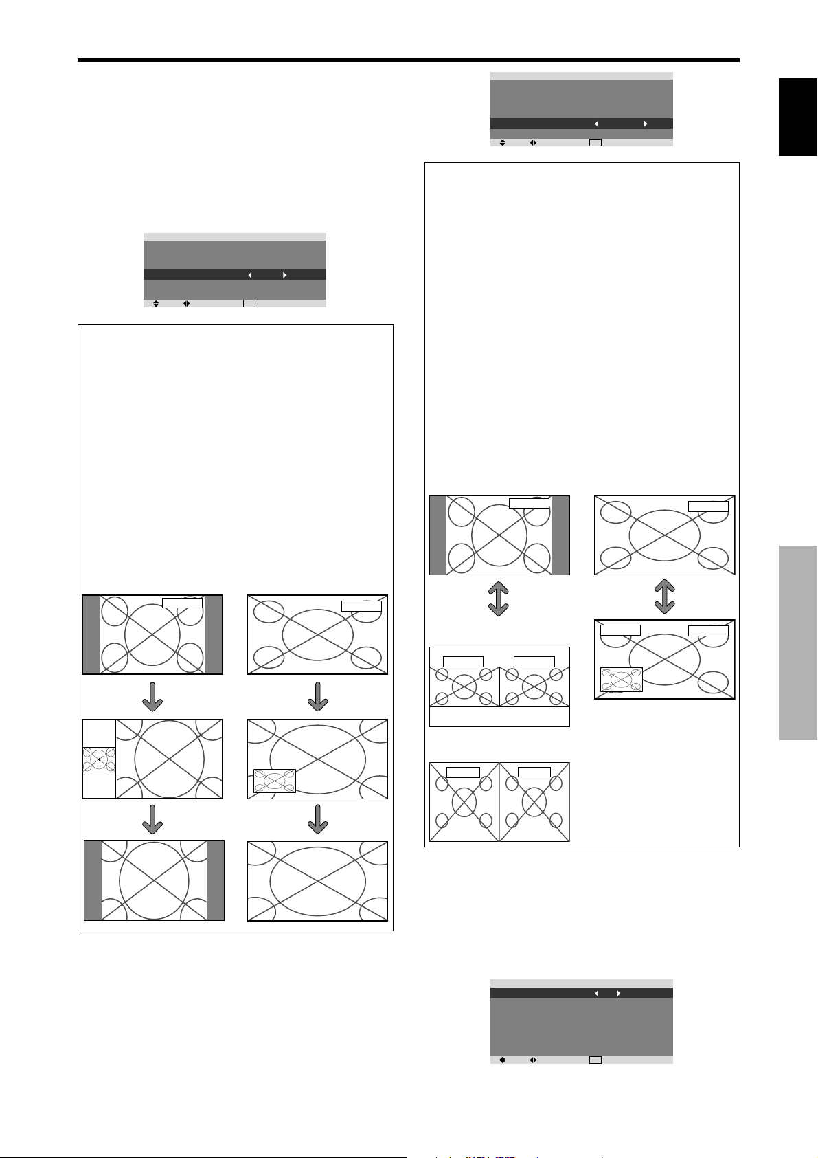
Displaying the entire image during DIGITAL
ZOOM operations
Use this function to display the entire image within the
sub screen together with an enlarged image on the main
screen.
Example: Setting “ZOOM NAV” to “S BY S”
On “ZOOM NAV” of “FUNCTION” menu, select “S BY
S”.
POWER MGT.
INPUT SKIP
SUB. P DETECT
ZOOM NAV
PICTURE FREEZE
LONG LIFE
SEL. ADJ.
FUNCTION
: OFF
: OFF
: AUTO
: S BY S
: S BY S1
: MANUAL
EXIT
RETURN
Information
ZOOM NAV Function
* This feature is available only for PC1 or PC2 input
signals.
* This feature does not function during multi screen mode.
* This feature does not function while PICTURE FREEZE
is operating.
* Providing a 2-screen display will cancel this function.
ZOOM NAV settings
OFF: W ill not show the entire image on the sub screen.
S BY S: Will show the entire image on the sub screen
of side-by-side mode.
BTM LFT~TOP LFT: Will show the entire image on
the sub screen of picture-in-picture mode.
Side-by-Side Picture-in-Picture
PC1DSUB
PC1DSUB
POWER MGT.
INPUT SKIP
SUB. P DETECT
ZOOM NAV
PICTURE FREEZE
LONG LIFE
SEL. ADJ.
FUNCTION
: OFF
: OFF
: AUTO
: BTM LEFT
: BTM LEFT
: MANUAL
EXIT
RETURN
Information
PICTURE FREEZE Function
* This feature is available only for PC1 or PC2 input
signals.
* This feature does not function during multi screen mode.
* Digital zoom is not available while this function is
operating.
* A further press of the ACTIVE SELECT button while
this function is operating will cancel this function.
* Providing a 2-screen display will cancel this function.
PICTURE FREEZE settings
OFF: Will not show the still image.
S BY S1, 2: The still images captured by pressing the
ACTIVE SELECT button will be shown on the sub
screen of side-by-side mode.
BTM LEFT~TOP LEFT: The still images captured by
pressing the ACTIVE SELECT button will be shown
on the sub screen of picture-in-picture mode.
Side-by-Side Picture-in-Picture
S BY S1
PICTURE FREEZE
PC1DSUB
ACTIVE
SELECT
button
PICTURE FREEZE
PC1DSUB
PC1DSUB
ACTIVE
SELECT
button
PC1DSUB
English
Zoom+/- button
SINGLE button
Displaying still images in the sub screen
This feature enables display in the sub screen of still images
captured by pressing the ACTIVE SELECT button.
Example: Setting “PICTURE FREEZE” to “BTM
LEFT”
On “PICTURE FREEZE” of “FUNCTION” menu, select
“BTM LEFT”.
or
S BY S2
PICTURE FREEZE
PC1DSUB
Reducing burn-in of the screen
The brightness of the screen, the position of the picture,
positive/negative mode and screen wiper are adjusted to
reduce burn-in of the screen.
On “LONG LIFE” of “FUNCTION” menu, select
“MANUAL”, then press the MENU/SET button.
The “LONG LIFE” screen appears.
ABL
ORBITER
INVERSE/WHITE
SCREEN WIPER
SOFT FOCUS
OSD ORBITER
OSD CONTRAST
SEL. ADJ.
LONG LIFE
: 100
: OFF
: OFF
: OFF
: OFF
: ON
: LOW
EXIT
RETURN
OSD (On Screen Display) Controls
23
En
Page 29
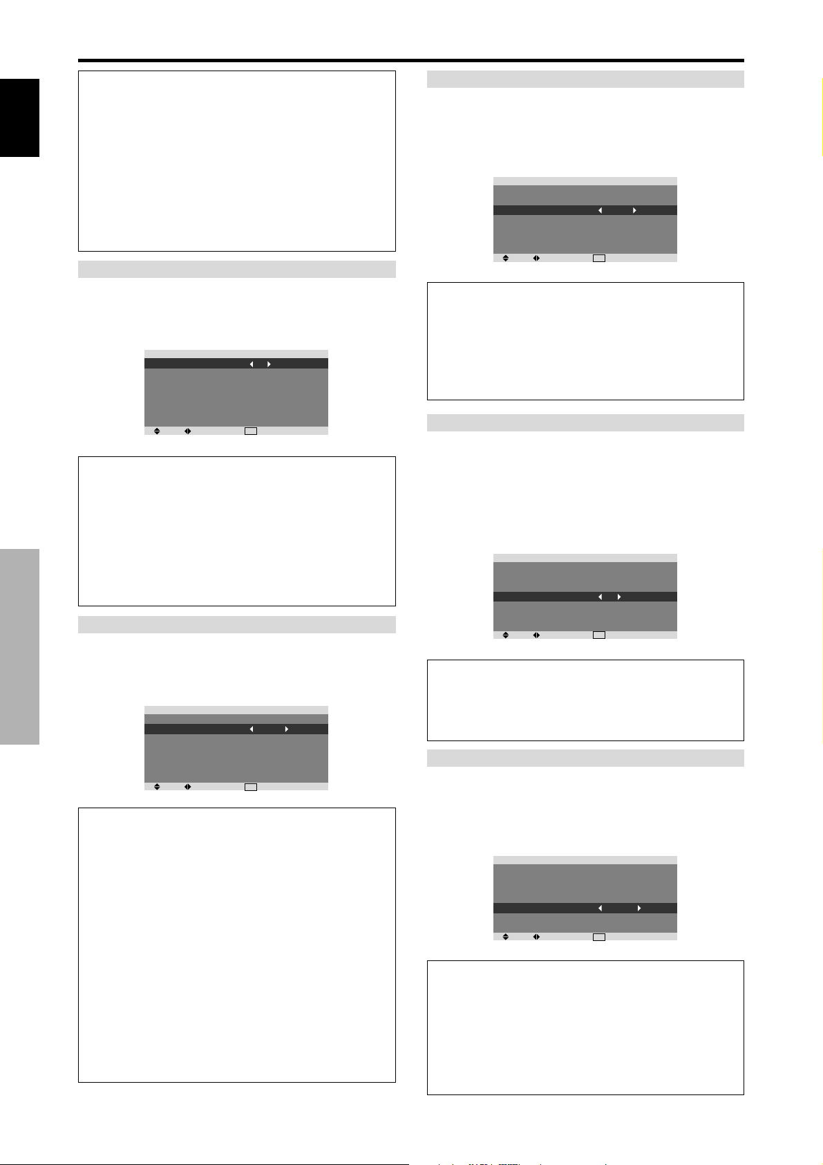
Information
When set to AUTO
English
Set automatically, as described below.
ABL: 100
ORBITER: AUTO1
INVERSE/WHITE: OFF
SCREEN WIPER: OFF
SOFT FOCUS: OFF
OSD ORBITER: ON
OSD CONTRAST: LOW
ABL (Auto Brightness Limiter)
Use this to activate the brightness limiter.
Example: Setting “ABL” to “75”
On “ABL” of “LONG LIFE” menu, select “75”.
ABL
ORBITER
INVERSE/WHITE
SCREEN WIPER
SOFT FOCUS
OSD ORBITER
OSD CONTRAST
SEL. ADJ.
Information
ABL settings
100: The brightness of the screen is adjusted
automatically to suit the picture quality.
75, 50, 25: Sets maximum brightness.
The brightness level decreases in the order of 75, 50,
25. 25 provides minimum brightness.
* These values are approximate.
ORBITER
Use this to set the picture shift.
Example: Setting “ORBITER” to “AUTO1”
On “ORBITER” of “LONG LIFE” menu, select “AUTO1”.
ABL
OSD (On Screen Display) Controls
ORBITER
INVERSE/WHITE
SCREEN WIPER
SOFT FOCUS
OSD ORBITER
OSD CONTRAST
SEL. ADJ.
Information
ORBITER settings
OFF: Orbiter mode does not function.
This is the default setting when PC signal is input.
AUTO1: The picture moves around the screen
intermittently, making the picture smaller. This is the
default setting when a Video, a COMPONENT or an
HDMI signal is input. Set to “OFF” when these signals
are not used.
AUTO2: The picture moves around the screen
intermittently, making the picture bigger.
* When a V ideo, a COMPONENT or an HDMI signal is
input, the AUTO1 and 2 functions will affect only the
moving picture and will not make the screen smaller or
bigger.
LONG LIFE
: 75
: OFF
: OFF
: OFF
: OFF
: ON
: LOW
EXIT
LONG LIFE
: 100
: AUTO1
: OFF
: OFF
: OFF
: ON
: LOW
EXIT
RETURN
RETURN
INVERSE/WHITE
Use this to set the inverse mode or to display a white screen.
Example: Setting “INVERSE/WHITE” to “WHITE”
On “INVERSE/WHITE” of “LONG LIFE” menu, select
“WHITE”.
ABL
ORBITER
INVERSE/WHITE
SCREEN WIPER
SOFT FOCUS
OSD ORBITER
OSD CONTRAST
SEL. ADJ.
LONG LIFE
: 100
: OFF
: WHITE
: OFF
: OFF
: ON
: LOW
EXIT
RETURN
Information
INVERSE/WHITE Settings
OFF: Inverse/white mode does not function.
INVERSE: The picture is displayed alternately between
positive image and negative image.
WHITE: The entire screen turns white.
SCREEN WIPER
When this is set to ON, a white vertical bar moves
repeatedly from the left and of the screen to the right end
at a constant speed.
Example: Setting “SCREEN WIPER” to “ON”
On “SCREEN WIPER” of “LONG LIFE” menu, select
“ON”.
ABL
ORBITER
INVERSE/WHITE
SCREEN WIPER
SOFT FOCUS
OSD ORBITER
OSD CONTRAST
SEL. ADJ.
LONG LIFE
: 100
: OFF
: OFF
: ON
: OFF
: ON
: LOW
EXIT
RETURN
Information
SCREEN WIPER
ON: The white vertical bar appears.
OFF: Screen wiper mode does not function.
SOFT FOCUS
Reduces edges and softens the image.
Example: Setting “SOFT FOCUS” to “LEVEL2”
On “SOFT FOCUS” of “LONG LIFE” menu, select
“LEVEL2”.
ABL
ORBITER
INVERSE/WHITE
SCREEN WIPER
SOFT FOCUS
OSD ORBITER
OSD CONTRAST
SEL. ADJ.
LONG LIFE
: 100
: OFF
: OFF
: OFF
: LEVEL2
: ON
: LOW
EXIT
RETURN
Information
SOFT FOCUS settings
OFF: Turns the SOFT FOCUS function off.
LEVEL1, 2, 3, 4: Acti vates the SOFT FOCUS setting.
The higher numbers create a softer image.
“SHARPNESS” can not be adjusted on the
“PICTURE” menu.
24
En
Page 30

OSD ORBITER
Use this to set OSD menu shift.
Example: Setting “OSD ORBITER” to “OFF”
On “OSD ORBITER” of “LONG LIFE” menu, select “OFF”.
ABL
ORBITER
INVERSE/WHITE
SCREEN WIPER
SOFT FOCUS
OSD ORBITER
OSD CONTRAST
SEL. ADJ.
LONG LIFE
: 100
: OFF
: OFF
: OFF
: OFF
: OFF
: LOW
EXIT
RETURN
Information
OSD ORBITER settings
ON: The position of the menu will be shifted by eight
dots each time OSD is displayed.
OFF: OSD will be displayed at the same position.
OSD CONTRAST
Use this to reduce the brightness of OSD menu.
Example: Setting “OSD CONTRAST” to “NORMAL”
On “OSD CONTRAST” of “LONG LIFE” menu, select
“NORMAL”.
ABL
ORBITER
INVERSE/WHITE
SCREEN WIPER
SOFT FOCUS
OSD ORBITER
OSD CONTRAST
SEL. ADJ.
LONG LIFE
: 100
: OFF
: OFF
: OFF
: OFF
: ON
: NORMAL
EXIT
RETURN
Signal Information Menu
Checking the frequencies, polarities of input
signals, and resolution
Use this function to check the frequencies and polarities
of the signals currently being input from a computer, etc.
On “MAIN MENU”, select “SIGNAL INFO.”, then press
the MENU/SET button.
The “SIGNAL INFORMATION” is displayed.
SIGNAL INFORMATION
H. FREQUENCY
V. FREQUENCY
H. POLARITY
V. POLARITY
MEMORY
RESOLUTION
PC: MEMORY will be displayed.
Others: MODE will be displayed.
: 48.4kHz
: 60.0Hz
: NEGATIVE
: NEGATIVE
: 24
: 1024
768
RETURN
EXIT
English
Information
OSD CONTRAST settings
NORMAL: OSD brightness is set to normal.
LOW: OSD brightness is set to lower.
OSD (On Screen Display) Controls
25
En
Page 31

English
Pin Assignments
mini D-Sub 15-pin connector
(Analog)
PC 1
5 4 3 2 1
10 9 8 7 6
15 14 13 12 11
Pin No.
1
2
3
4
5
6
7
8
9
10
11
12
13
14
15
Signal (Analog)
Red
Green or sync-on-green
Blue
No connection
Ground
Red ground
Green ground
Blue ground
No connection
Sync signal ground
No connection
Bi-directional DATA (SDA)
Horizontal sync or Composite sync
Vertical sync
Data clock
Pin Assignments
26
En
Page 32

Table of Signals Supported
Supported resolution
• When the screen size is 4:3, each signal is converted to a 1024 dots768 lines signal. (Except for *
• When the screen size is D BY D, the picture is displayed in the original resolution.
• When the screen size is FULL, each signal is converted to a 1365 dots768 lines signal. (Except for *
Computer input signals supported by this system
Model
Signal Type
IBM PC/AT*
8
compatible
computers
Apple
Macintosh*
Work Station
(EWS4800)
Work Station(HP)
6 *8
*
8
8
*
Work Station
8
(SUN)
*
Work Station
(SGI)
IDC-3000G
NTSC525P
Dots lines
640400
640480
848480
852480*
800600
1024768
1152864
1280768
1280800*
1280854*
1360765
1360768
1376768
12801024
16801050*
16001200
19201200*
19201200RB
640480
832624
1024768
1152870
1440900*
12801024
12801024
1152900
12801024
1024768
12801024
640480
Vertical
frequency
(Hz)
1
9
9
9
9
9
*
9
70.1
59.9
72.8
75.0
85.0
100.4
120.4
60.0
60.0
56.3
60.3
72.2
75.0
85.1
99.8
120.0
60.0
70.1
75.0
85.0
100.6
75.0
56.2
59.8*
69.8*
60.0
60.0
60.0
60.0
59.9
60.0
75.0
85.0
100.1
60.0
60.0
65.0
70.0
75.0
85.0
60.0
60.0
66.7
74.6
74.9
75.1
60.0
60.0
71.2
72.0
66.0
76.0
76.1
60.0
60.0
59.9
9
9
Horizontal
frequency
(kHz)
31.5
31.5
37.9
37.5
43.3
51.1
61.3
31.0
31.7
35.2
37.9
48.1
46.9
53.7
63.0
75.7
48.4
56.5
60.0
68.7
80.5
67.5
45.1
48.0*
56.0*
49.7
53.1
47.7
47.7
48.3
64.0
80.0
91.1
108.5
65.3
75.0
81.3
87.5
93.8
106.3
74.6
74.0
35.0
49.7
60.2
68.7
56.0
64.6
75.1
78.1
61.8
71.7
81.1
49.7
63.9
31.5
Sync Polarity Presence
9
9
Horizontal
NEG
NEG
NEG
NEG
NEG
NEG
NEG
POS
NEG
POS
POS
POS
POS
POS
POS
POS
NEG
NEG
POS
POS
NEG
POS
NEG
NEG
NEG
NEG
NEG
POS
POS
NEG
POS
POS
POS
POS
NEG
POS
POS
POS
POS
POS
NEG
NEG
Sync on G
Sync on G
Sync on G
Sync on G
NEG
NEG
NEG
– –
C Sync
C Sync
C Sync
– –
– –
NEG
Vertical
NEG
NEG
NEG
NEG
NEG
NEG
NEG
POS
NEG
POS
POS
POS
POS
POS
POS
POS
NEG
NEG
POS
POS
NEG
POS
NEG
POS
POS
NEG
NEG
POS
POS
POS
POS
POS
POS
POS
NEG
POS
POS
POS
POS
POS
NEG
NEG
Sync on G
Sync on G
Sync on G
Sync on G
NEG
NEG
NEG
– –
C Sync
C Sync
C Sync
– –
– –
NEG
Horizontal
YES
YES
YES
YES
YES
YES
YES
YES
YES
YES
YES
YES
YES
YES
YES
YES
YES
YES
YES
YES
YES
YES
YES
YES
YES
YES
YES
YES
YES
YES
YES
YES
YES
YES
YES
YES
YES
YES
YES
YES
YES
YES
– –
– –
– –
– –
YES
YES
YES
– –
– –
– –
– –
– –
– –
YES
Vertical
YES
YES
YES
YES
YES
YES
YES
YES
YES
YES
YES
YES
YES
YES
YES
YES
YES
YES
YES
YES
YES
YES
YES
YES
YES
YES
YES
YES
YES
YES
YES
YES
YES
YES
YES
YES
YES
YES
YES
YES
YES
YES
– –
– –
– –
– –
YES
YES
YES
– –
– –
– –
– –
– –
– –
YES
2, 3, 4
)
3
)
Screen Size
4:3
2
YES*
YES
YES
YES
YES
YES
YES
– –
– –
YES
YES
YES
YES
YES
YES
YES
3
YES*
3
YES*
3
YES*
3
YES*
3
YES*
YES
– –
– –
– –
– –
– –
– –
– –
– –
4
YES*
4
YES*
4
YES*
4
YES*
– –
YES
YES
YES
YES
YES
– –
– –
YES
YES
3
YES*
YES
– –
4
YES*
4
YES*
4
YES*
YES
YES
4
YES*
3
YES*
4
YES*
7
YES*
D BY D
– –
– –
– –
– –
– –
– –
– –
– –
– –
– –
– –
– –
– –
– –
– –
– –
– –
– –
– –
– –
– –
– –
YES
YES
YES
– –
– –
– –
– –
– –
– –
– –
– –
– –
– –
– –
– –
– –
– –
– –
– –
– –
– –
– –
– –
– –
– –
– –
– –
– –
– –
– –
– –
– –
– –
– –
FULL
(16:9)
YES
YES
YES
YES
YES
YES
YES
YES
YES
YES
YES
YES
YES
YES
YES
YES
YES
YES
YES
YES
YES
YES
YES
YES
YES
YES
YES
YES*
YES*
YES
YES
YES
YES
YES
YES
YES
YES
YES
YES
YES
YES
YES
YES
YES
YES
YES
YES
YES
YES
YES
YES
YES
YES
YES
YES
YES*
RGB
select*
– –
STILL
– –
STILL
– –
– –
– –
WIDE2
WIDE1
STILL
STILL
– –
– –
– –
– –
– –
STILL
– –
STILL
– –
– –
STILL
WIDE1
WIDE4
WIDE1
WIDE1
WIDE2
3
WIDE1
3
WIDE1
WIDE2
STILL
– –
– –
– –
WIDE4
– –
– –
– –
– –
– –
WIDE2
WIDE3
– –
– –
WIDE1
WIDE1
– –
– –
– –
– –
– –
– –
– –
– –
– –
7
MOTION
5
Memory
41
42
19
17
11
12
13
14
15
43
44
24
25
26
27
45
51
52
23
66
21
37
22
22
53
29
30
40
47
38
54
55
56
57
58
81
88
16
28
39
89
29
48
59
60
61
30
62
29
32
English
4
5
7
8
9
Table of Signals Supported
Table of Signals Supported
6
27
En
Page 33

English
*1 Only when using a graphic accelerator board that is capable of displaying 852480.
*2 This signal is converted to a 1024 dots 640 lines signal.
*3 The picture is displayed in the original resolution.
*4 The aspect ratio is 5:4. This signal is converted to a 960 dots768 lines signal.
*5 Normally the RGB select mode suite for the input signals is set automatically . If the picture is not displayed properly , set the
RGB mode prepared for the input signals listed in the table above.
*6 To connect the monitor to Macintosh computer , use the monitor adapter (D-Sub 15-pin) to your computer's video port.
*7 Other screen modes (ZOOM and WIDE) are a vailable as well.
*8 When vie wing a moving picture at a vertical frequenc y greater than 65Hz, the picture may sometimes be unstable (jumpy).
If this occurs, please set the refresh rate of the external equipment to 60Hz.
T o view 480I@60Hz (480 interlaced lines, 60Hz refresh rate) or 576I@50Hz (576 interlaced lines, 50Hz refresh rate) when
sync polarity is “Sync on Green”, set “RGB SELECT” to “MOTION”.
*9 CVT standard compliant.
NOTE:
• While the input signals comply with the resolution listed in the table above, you may have to adjust the position and size of the
picture or the fine picture because of errors in synchronization of your computer.
• When a 1280 dots
• This monitor has a resolution of 1365 dots
equivalent.
• With digital input some signals are not accepted.
• The sync may be disturbed when a nonstandard signal other than the aforementioned is input.
• If you are connecting a composite sync signal, use the HD terminal.
1024 lines signal or 1600 dots 1200 lines signal is input to the monitor, the picture will be compressed.
768 lines. It is recommended that the input signal should be XGA, wide XGA, or
•“IBM PC/AT” and “XGA” are re gistered trademarks of International Business Machines, Inc. of the United States.
•“Apple Macintosh” is a registered trademark of Apple Computer, Inc. of the United States.
Table of Signals Supported
28
En
Page 34

Troubleshooting
If the picture quality is poor or there is some other problem, check the adjustments, operations, etc., before requesting service.
Symptom
Mechanical sound is heard.
The unit emits a crackling sound.
Picture is disturbed.
Sound is noisy.
Remote control operates erroneously.
The remote control does not work.
Monitor’s power does not turn on when the
remote control’s power button is pressed.
Monitor does not operate when the remote
control’s buttons are pressed.
No sound or picture is produced.
Picture appears but no sound is produced.
Poor picture with VIDEO signal input.
Poor picture with RGB signal input.
Tint is poor or colors are weak.
Nothing appears on screen.
Part of picture is cut off or picture is not
centered.
Image is too large or too small.
Picture is unstable.
STANDBY/ON indicator is lighted in red.
STANDBY/ON indicator is blinking in red.
STANDBY/ON indicator is blinking in green
and red, or green.
Checks
• Maybe the sound from the cooling fans used to prevent over heating.
• Are the image and sound normal?
• Is a connected component set directly in front or at
the side of the display?
• Are the remote control’s batteries worn out?
• Is the monitor’s power cord plugged into a power
outlet?
• Are all the monitor’s indicators off?
• Are the remote control’s batteries worn out?
• Is the remote control pointed at the monitor, or is
there an obstacle between the remote control and
the monitor?
• Is direct sunlight or strong artificial light shining on
the monitor’s remote control sensor?
•
Are the remote control’s batteries worn out?
• Is the monitor’s power cord plugged into a power
outlet?
• Is the volume set at the minimum?
• Is the muting mode set?
• Are the speakers properly connected?
• Is AUDIO INPUT set correctly?
• Improper control setting.
Local interference.
Cable interconnections.
Input impedance is not correct level.
• Improper control setting.
Incorrect RGB connector pin connections.
• Are the tint and colors properly adjusted?
• Is the computer’s power turned on?
• Is a source connected?
• Is the power management function in the standby
or off mode?
• Is the position adjustment appropriate?
• Is the screen size adjustment appropriate?
• Is the computer’s resolution setting appropriate?
• Horizontal and / or vertical sync signal is not
present when the Intelligent Power Manager
control is on.
• The temperature inside the main unit has become
too high and has activated the protector.
——————
• If there are no abnormalities in the image and sound,
the noise is caused by the cabinet reacting to
changes in temperature. This will not affect
performance.
• Leave some space between the display and the
connected components.
• Replace both batteries with new ones.
• Plug the monitor’s power cord into a power outlet.
• Press the power button on the monitor to turn on the
power.
• Replace both batteries with new ones.
• Point the remote control at the monitor’s remote
control sensor when pressing buttons, or remove the
obstacle.
• Eliminate the light by closing curtains, pointing the
light in a different direction, etc.
• Replace both batteries with new ones.
• Plug the monitor’s power cord into a power outlet.
• Increase the volume.
• Press the remote control’s MUTING button.
• Connect the speakers properly.
• Set AUDIO INPUT on the SOUND menu correctly.
• Adjust picture control as needed.
Try another location for the monitor.
Be sure all connections are secure.
• Adjust picture controls as needed.
Check pin assignments and connections.
• Adjust the tint and color (under PICTURE).
• Turn on the computer’s power.
• Connect source to the monitor.
• Operate the computer (move the mouse, etc.).
• Adjust the SCREEN properly.
• Press the SCREEN SIZE button on the remote
control and adjust properly.
• Set to the proper resolution.
• Check the input signal.
• Promptly switch off the power of the main unit and
wait until the internal temperature drops. See*1.
• Prompty switch off the power of the main unit. See
*2.
Remedy
*1 Overheat protector
If the monitor becomes too hot, the overheat protector will be activ ated and the monitor will be turned off. If this happens, turn off the po wer to the monitor
and unplug the power cord. If the room where the monitor is installed is particularly hot, move the monitor to a cooler location and wait for the monitor
to cool for 60 minutes. If the problem persists, contact your dealer.
*2 In the following case, power off the monitor immediately and contact your dealer or authorized Service Center.
The monitor turns off 5 seconds after powering on and then the STANDBY/ON indicator blinks. It indicates that the power supply circuit, plasma display
panel, temperature sensor, or one or more fans hav e been damaged.
English
Troubleshooting
29
En
Page 35

Specifications
Screen Size 1351(H)760(V) mm
English
Specifications
Aspect Ratio 16 : 9
Resolution 1365(H)768(V) pixels
Signals
Input Terminals
Sound output 9W+9W at 6 ohm
Power Supply AC220-240V 50/60Hz
Current Rating 3.7A (maximum)
Power Consumption 540W (typical) (standby 1.8W)
Dimensions 1502 (W)912 (H)126(D) mm
Weight 68.0 kg / 149.9 lbs (without stand)
Environmental Considerations
Other Features Motion compensated 3D Scan Converter (NTSC,
53.2"(H)29.9"(V) inches
diagonal 61"
Synchronization Range Horizontal : 15.5 to 110 kHz
(automatic : step scan)
Vertical : 50.0 to 120 Hz
(automatic : step scan)
Input Signals RGB, NTSC (3.58/4.43), PAL (B,G,M,N),
P AL60, SECAM, HD*
1
, DVD*1 , DTV*
PC
Visual 1 (Analog) mini D-sub 15-pin1
Visual 2 (Analog) BNC (R, G, B, H/CS, V)1*
2
Video
Visual 1 BNC1
Visual 2 RCA-pin1
Visual 3 S-Video:DIN 4-pin1
COMPONENT
Visual 1 RCA-pin (Y, PB[CB], PR[CR])1*
Visual 2 BNC (Y, PB[CB], PR[CR])1*
HDMI HDMI connector*
3
1, *2
Audio Stereo RCA3 (Selectable)
RS-232C D-sub 9-pin1
59.1 (W)35.9 (H)5.0 (D) inches
Operating Temperature 0°C to 40°C / 32°F to 104°F
PAL, 480I, 576I, 525I, 625I, 1035I, 1080I), 2-3
pull down Conv erter (NTSC, 480I, 525I, 1035I,
1080I (60Hz)), 2-2 pull down Conv erter (PAL,
576I, 625I, NTSC, 480I, 525I), Digital Zoom
Function (100-900% Selectable), Self Diagnosis,
Image Burn reduction tools (ABL, INVERSE,
WHITE, ORBITER, SCREEN WIPER), Color
Temperature select (high/middle/middle low/low,
user has 4 memories), Auto Picture, Input Skip,
Color MGT, Low Tone (3 mode), Gamma
Correction (4 mode), Plug and play (DDC1,
DDC2b, HDMI:E-DDC), Split screen operations
1
The features and specifications may be subject to change without
notice.
1
*1COMPONENT input signals supported on this system
480P (60 Hz) 480I (60 Hz) 525P (60 Hz)
525I (60 Hz) 576P (50Hz) 576I (50Hz)
625P (50Hz) 625I (50Hz) 720P (60 Hz)
1035I (60 Hz) 1080I (50 Hz) 1080I (60 Hz)
2
*
The 5-BNC connectors are used as PC2 and COMPONENT2 input.
Select one of them under “BNC INPUT”.
3
*
HDMI input signals supported on this system.
Supported Signals
• 640480P @ 60Hz • 19201080I @ 50Hz
• 1280720P @ 60Hz • 720576P @ 50Hz
• 19201080I @ 60Hz • 1440 (720)576P @ 50Hz
• 720480P @ 60Hz • 1280720P @ 50Hz
• 1440 (720)480I @ 60Hz
Note: In some cases a signal on the plasma monitor may not be displayed
properly. The problem may be an inconsistency with standards from
the source equipment (DVD, Set-top box, etc...). If you do experience
such a problem please contact your dealer and also the manufacturer of
the source equipment.
30
En
Page 36

Mode d’emploi
Nous vous remercions d’avoir acquis cet appareilPIONEER.
Avant d’utiliser cet écran à plasma, veuillez lire attentivement
les “Recommandations importantes” et les “Mode d’emploi”
de façon à connaître comment employer convenablement
l’écran à plasma.
Conservez le mode d’emploi pour référence. Vous pourriez
en avoir besoin plus tard.
Français
Remarques sur l’installation:
Ce produit est vendu en assumant qu’il sera installé par un
personnel suffisamment expérimenté et qualifié. Faites toujours
réaliser le montage et l’installation par un spécialiste ou par votre
revendeur.
PIONEER ne peut être tenu responsable pour tout dommage
causé par une erreur d’installation ou de montage, une mauvaise
utilisation ou un désastre naturel.
Remarque pour le revendeur:
Après l’installation, assurez-vous de remettre ce mode d’emploi à
l’utilisateur et de lui expliquer comme utiliser ce produit.
Fr
Page 37

Recommandations importantes
Précaution
Veuillez lire avec attention ce manuel avant d’utiliser le moniteur à
plasma et le conserver accessible pour s’y référer ultérieurement.
RISQUE D’ELECTROCUTION
ATTENTION: POUR EVITER TOUT RISQUE
D’ELECTROCUTION, NE PAS OUVRIR LE
Français
AFIN D’EVITER TOUT RISQUE D’INCENDIE OU
D’ELECTROCUTION, NE PAS EXPOSER CET APPAREIL
A LA PLUIE OU A L’HUMIDITE. NE PAS BRANCHER LA
PRISE D’ALIMENTATION POLARISEE DANS UNE PRISE
MURALE AVEC UNE RALLONGE OU UN ADAPTATEUR
MULTIPRISE SI LES FICHES NE PEUVENT ETRE
INSEREES COMPLETEMENT. EVITER D’OUVRIR LE
BOITIER CAR CELUI-CI PROTEGE DES COMPOSANTS
FONCTIONNANT A HAUTE TENSION. EN CAS DE
PROBLEME, S’ADRESSER A UN REPARATEUR
SPECIALISTE.
BOITIER. A L’INTERIEUR, AUCUNE PIECE
NE NECESSITE L’INTER-VENTION DE
L’UTILISATEUR. EN CAS DE PROBLEME,
S’ADRESSER A UN REPARATEUR
SPECIALISTE.
Ce symbole est une mise en garde contre les
risques d’électrocution que présentent certaines
parties dépourvues d’isolation à l’intérieur de
l’appareil. Il est donc dangereux d’établir le
moindre contact avec ces parties.
Ce symbole avertit l’utilisateur que d’importantes
informations sont fournies sur le fonctionnement
ou l’entretien de cet appareil. De ce fait, il faut
lire attentivement ces instruc-tions pour éviter
tout problèm
Avertissements et précautions de
sécurité
Ce moniteur à plasma a été conçu et fabriqu pour une utilisation
fiable et durable. Il ne nécessite aucun entretien en dehors du
nettoyage. Voir la section “Méthode de nettoyage du moniteur à
Recommandations importantes
plasma” plus loin.
Le panneau à affichage plasma est constitué de fines particules
d’images (cellules) dont plus de 99,99%sont actives. Certaines
d’entre elles ne produisent pas de lumière ou restent allumées.
Pour des raisons de sécurité et pour éviter d’endommager
l’appareil, lire attentivement les instructions suivantes.
Pour éviter les risques d’éléctrocution et d’incendie:
1. Laisser suffisamment d’espace autour de l’appareil pour la
ventilation et éviter toute augmentation excessi ve de la température
interne. Ne pas couvrir les fentes d’aération ou installer l’appareil
dans un endroit trop exigu.
Si vous installez l’appareil dans un espace clos, assurezvous qu’il y
ait suffisamment d’espace au dessus pour permettre l’air chaud de
s’élever et de s’é vacuer.
Si la température du moniteur devient excessi ve, la protection contre
les surchauffes entrera en action et coupera l’alimentation. Dans ce
cas, éteindre l’appareil et débrancher le câble d’alimentation. Si la
température de la pièce dans laquelle se trouve le moniteur est
particulièrement élevée, déplacer celui-ci dans un endroit plus frais
et attendre environ 60 minutes qu’il refroidisse. Si le problème
persiste, prendre contact avec votre re v endeur.
2. Ne pas raccorder la prise d’alimentation polarisée de ce périphérique
à une rallonge ou une prise murale si les fiches ne peuvent pas être
complètement insérées.
ATTENTION..
NE PAS OUVRIR
AVERTISSEMENT
3. Ne pas exposer cet appareil à la pluie ou à l’humidité.
4. Eviter d’endommager le câble d’alimentation et ne pas le modifier .
5. Débrancher le câble d’alimentation électrique pendant les orages
ou les longues périodes d’inactivité.
6. Ne pas ouvrir le boîtier protégeant les parties dangereuses
fonctionnant hauts voltages. Si l’appareil est endommagé de cette
manière, la garantie sera annulée. De plus, les risques d’électrocution
grave sont grands.
7. Ne pas essayer d’intervenir ou de réparer l’appareil. Le fabricant
décline toute responsabilité en cas de blessure corporelle ou de dégâts
matériels résultant d’une opération d’entretien quelconque effectuée
par des personnes non qualifiées ou résultant de l’ouverture du
couvercle arrière. S’adresser au service après-vente autorisé.
REMARQUE:
Pour raccorder un ordinateur à ce moniteur, procéder à
l’aide d’un câble RGB à âme de ferrite aux deux extrémités.
Si vous ne faites pas cela, le moniteur ne sera pas
conforme aux normes obligatoires CE et C-Tick.
Fixation des tores en ferrite :
Monter les tores en ferrite aux deux extrêmités du câble
d’alimentation électrique (fourni).
Refermez les agrafes jusqu’ entendre un déclic.
Câble d’alimentation (fourni)
tore
Pour éviter tout dommage et assurer une utilisation durable:
1. Utiliser seulement une alimentation en courant de 220-240 V 50/60
Hz. Toute utilisation prolongée avec un courant supérieur à 220240 V risque de diminuer la durée de vie de l’appareil et même de
provoquer un incendie.
2. Manipuler l’appareil avec précautions lors de son installation, ne
pas le laisser tomber.
3. L ’installer loin de toute source de chaleur ou de poussière. Ne pas
l’exposer au soleil.
4. Eviter la pénétration de liquides ou petits objets métalliques
l’intérieur de l’appareil. En cas d’incident de ce genre, débrancher
le câble d’alimentation électrique et confier le moniteur à un service
après-vente agréé.
5. Ne pas cogner ou rayer la surface de l’écran, des déformations de
l’image en résulteraient.
6. Pour un montage et une installation correcte, il est fortement
recommandé de faire appel à un rev endeur agréé et qualif ié .
7. Comme c’est le cas pour tout affichage à base de phosphore (comme
un moniteur CRT, par exemple), la puissance de lumière baisse
graduellement au cours de la vie du panneau d’affichage à plasma.
8. Pour éviter tout risque de sulfuration, il est fortement conseillé de
ne pas installer l’appareil dans un vestiaire, un bain public ou un
bain de source thermale.
9. Ne pas utiliser dans un véhicule en marche car l’unité pourrait tomber
ou glisser et provoquer des blessures.
10.
Pour éviter l ‘inflammation ou les chocs électriques, ne pas placer l’unité
sur la tranche, à l’envers ou av ec l’écran vers le bas ou vers le haut.
Méthode de nettoyage du moniteur à plasma:
1. Utiliser un chiffon (fourni) ou un chiffon doux et sec pour nettoyer
le panneau avant et le cadre. Ne jamais utiliser de solvants de type
alcool ou diluant pour le nettoyage de ces surfaces.
2. Nettoyer les prises d’aération du plasma en procédant à l’aide d’une
brosse à poils doux fixée à un aspirateur.
3. Pour garantir la bonne ventilation du moniteur, nettoyer les prises
d’air tous les mois. Un nettoyage plus fréquent peut s’avérer
nécessaire selon les conditions environnantes dans lesquelles le
moniteur à plasma est utilisé.
tore
i
Fr
Page 38

Pour éviter les risques de brûlage du luminophore, les mesures
suivantes sont recommandées:
Comme tous les périphériques d’aff ichage à base luminophore et tous les
autres affichages gaz plasma, les moniteurs plasma peuv ent être sujets au
brûlage du luminophore dans certaines circonstances. Certaines conditions
d’utilisation, telles que l’aff ichage continu d’une image statique pour une
durée prolongée, peuvent causer le brûlage du luminophore si aucune
précaution n’est prise. Pour protéger votre investissement dans ce moniteur
à plasma, veuillez suivre les directives et les conseils suivantes pour
minimiser l’occurence le marquage de l’écran
*S’assurer de mettre en marche et d’utiliser l’économiseur d’écran
chaque fois que c’est possible, pendant l’utilisation avec une source
d’entrée venant d’ un ordinateur .
* Afficher une image en mouvement aussi souvent que possible.
* Changer la position de l’affichage de menu de temps à autre.
* Toujours couper l’alimentation après la fin de l’utilisation du
moniteur.
Si le moniteur à plasma est en usage continu ou de longue durée, prendre
les mesures suivantes afin d’éviter l’occurence le brûlage du
luminophore:
* Abaisser le niveau de l’image (contraste, luminance) autant que
possible, sans faire perdre la lisibilit de l’image.
* Afficher une image avec de nombreuses couleurs et graduations de
couleur. (par ex. des images photo-graphiques ou photo-réalistes).
*Créer un contenu d’image avec un contraste minimal entre les zones
sombres et les zones claires, par exemple des caractères blancs sur
un fond noir. Utiliser des couleurs complémentaires ou pastels le
plus souvent possible.
* Eviter d’afficher des images avec peu de couleurs et des limites nettes
et clairement définies entre les couleurs.
* REMARQUE: Le brûlage de l’écran n’est pas couvert par la
garantie.
Contactez un revendeur agréé ou un rev endeur de marque pour d'autres
procédures qui conviendront le mieux à v os besoins particuliers.
Ce produit est conforme à la directive relative aux
appareils basse tension (73/23/CEE), à la directive
CE relative à la compatibilité electromagnétique (89/
336/CEE, amendements 92/31/CEE et 93/68/CEE).
Attention
Cet modèle est fait pour être utilisé avec les accessoires
optionnels suivants. Toute utilisation avec d’autres
accessoires optionnels peut entraîner une instabilité pouvant
causer des blessures.
Support plateau : PDK-1014
Fixation murale : PDK-WM03
Français
AVERTISSEMENT:
EN POSITIONNANT L’EQUIPEMENT, S’ASSURER QUE
LA FICHE ET LA PRISE DE RACCORDEMENT DE
L’ALIMENTATION SONT FACILEMENT ACCESSIBLES.
Recommandations importantes
ii
Fr
Page 39

iii
Fr
Page 40

Table des matière
Installation ...................................................... 2
Ventilation requise pour le montage de l’ensemble ....... 2
Comment fixer les fixations métalliques sécurisées et
les vis fournies ...................................................... 2
Fixation des câbles ................................................... 3
Comment utiliser la télécommande ............................. 3
Mise en place et remplacement des piles ......................3
Distance de fonctionnement .........................................3
Manipulation de la télécommande ...............................3
Noms des composants et leur fonction ............... 4
Vue de face ............................................................. 4
Vue arrière / Raccordements..................................... 5
Télécommande ........................................................ 6
Fonctions de base ............................................. 7
POWER (MARCHE/ARRÊT) ...................................... 7
Pour mettre en marche et arrêter l’appareil :................. 7
VOLUME ................................................................ 7
Pour régler le volume sonore :......................................7
MUTING (SOURDINE) .............................................. 7
Pour mettre le son en sourdine: ................................... 7
DISPLAY (AFFICHAGE) ............................................. 7
Pour vérifier les réglages :............................................ 7
ZOOM NUMERIQUE ............................................... 7
OFF TIMER (ARRÊT TEMPORISÉ) ................................ 7
Réglage de la temporisation de l’alimentation :............ 7
Vérification du temps restant avant l’arrêt automatique: ........
Annulation de la temporisation de l’alimentation: ........ 7
Fonctionnement avec écran large (WIDE) ............ 8
Opération de taílle d’écran (manuel) .......................... 8
Visualisation de vidéos ou de disques laser vidéo......... 8
Opération de taílle décran sur des signaux d’ordínateur ......
Opérations de DECOUPE D’IMAGE ..................... 10
Affichage de deux images en même temps sur l’écran ......
Opérations en mode côte-à-côte................................. 10
Opérations en mode image-dans-image .....................11
Sélection des signaux d’entrée à afficher.................... 11
Zoomer les images ..................................................... 11
Réglage des commandes OSD ................................... 11
10
Commandes OSD (MENUS ÉCRAN)...................... 12
Opérations de menu............................................... 12
Sélection de la langue des menus ............................. 12
Arborescence de menus .......................................... 13
Menu de réglage de l’image ................................... 15
Mise en mémoire des réglages de l’image.................. 15
Réglage de l’image .................................................... 15
Réduction du bruit de l’image (parasites) ................... 15
Réglage de la température de couleur......................... 16
Ajustement des couleurs à la qualité désirée .............. 16
Modification de la courbe gamma ..............................16
Réglages des tons bas................................................. 16
Réglage du niv eau piédestal (niveau des noirs)........... 17
Réglage des couleurs..................................................17
Réglage de l’image pour s’adapter au format cinéma .......
Réglage du SÉLECTION AV en fonction de l’éclairage
ambiant ...................................................................17
Menu des réglage du son........................................ 18
Réglage des aigus des grav es et de la balance
gauche/droit ............................................................... 18
Réglage des emplacements des connecteurs audio .........
Menu des réglage de l’écran ................................... 18
Réglage de la position, de la taille, de la PHASE et de la
HORLOGE ............................................................. 18
17
18
Menu des réglages de SET UP ................................. 19
Réglage des connecteurs PC2/COMPONENT2 .........19
Réglage du connecteur PC1 ....................................... 19
Réglage de l´image haute définition vers une taille
d´ecran qui convient ................................................ 19
Réglage d’une image d’ordinateur v ers l’écran de
sélection de RGB correct......................................... 19
Réglage du niv eau des noirs pour un signal HDMI .... 20
Sélection du format du signal vidéo ........................... 20
Réglage de la couleur de fond affichée en cas d’absence
de signal .................................................................. 20
Réglage du niveau des gris pour les côtés de l’écran.........
Réglage de la taille de l’écran pour une entrée vidéo
S1/S2....................................................................... 21
’
Activation/désactivation de l
Réglage de la position du menu .................................21
Restauration des valeurs par défaut ............................ 22
Menu des réglages de FONCTION .......................... 22
Sélection de l’alimentation pour images d’ordinateur.......
Indicateur STANDBY/ON
Réglage de SELECT SKIP ........................................ 23
Effacement de l’image de l’écran secondaire
lorsqu’il n’y a pas de signal d’entrée ....................... 23
Affichage de l’image en entier lors du fonctionnement
du DIGITAL ZOOM ............................................... 23
Affichage d’images f ix es sur l’écran secondaire......... 24
7
Réduction de la rémanence de l’image sur l’écran..........
Menu des réglages de SIGNAL INFORMATION ....... 26
Vérification des fréquences, polarités des signaux
d’entrée, et de la résolution...................................... 26
écran d’information ......21
..............................................
21
22
22
24
Français
Fonctions des broches ..................................... 27
9
Connecteur mini D-sub à 15 broches (analogique) ..... 28
Tableau des signaux pris en charge par l’appareil....
Résolutions compatible............................................ 28
28
Dépannage..................................................... 30
Caractéristiques ............................................. 31
Contenu du colis
Moniteur à plasma
Cordon d’alimentation
Télécommande avec 2 piles R6 AAA
Manuel
Garantie
Fixations métalliques sécurisées (x2) *
Tores en ferrite (x2)
Collier de câble (x5)
Chiffon
* Celles-ci sont des crochets pour fixer l’unité au mur af in
d’éviter qu’elle se renverse à cause d’un choc extérieur
lorsqu’on utilise le support (option). Fixer les accrochages
métalliques sécurisés dans les trous situés à l’arrière du
moniteur en utilisant les vis pour l’accrochage métallique
sécurisé (voir page 2).
Table des matière
Options
• Unité de montage mural
• Support
1
Fr
Page 41

Français
Installation
Le socle-support optionnel peut être attaché au moniteur à plasma selon l’une des deux méthodes suivantes :
* Position verticale. (Voir la figure A)
* Position horizontale avec l’écran face vers le bas (Voir la figure B). Poser la feuille de protection, enveloppant le moniteur
dans son emballage, sous la surface de l’écran pour la protéger contre les rayures.
* Ne pas toucher ou saisir l’écran pendant le transport de l’appareil.
• Cet appareil ne peut pas être installé indépendamment. S’assurer d’utiliser un support ou une
unité de montage d’origine. (Unité de montage mural, support, etc)
* Voir page 1.
• Pour effectuer une installation et un mon-tage corrects, il est recommandé de faire appel au
concessionnaire spécialisé et agréé.
Si la procédure de montage n’est pas correctement suivie, l’appareil peut être endommagé et
l’installateur s’expose à des risques de blessure.
La garantie de l’appareil ne couvre pas les dégâts occasionnés par une installation
* N’utilisez le que le kit ou support de montage fourni par le fabricant et les options listées ci-après.
Installation
Figure A
Figure B
Ventilation requise pour le montage
de l’ensemble
Afin de dissiper la chaleur, laisser un espace libre entre
les objets environnants comme indiqué sur le schéma cidessous lors de l’installation.
Mur
50mm (2")
50mm (2")
(2")
mm
Mur
Pour l’installation ou le transport,
procéder à l’aide des poignées se
trouvant au dos et en haut de l’écran.
Comment fixer les fixations
métalliques sécurisées et les vis
fournies
Ces fixations permettent de fixer l’unité au mur afin
d’éviter qu’elle se renverse à cause d’un choc extérieur
lorsqu’on utilise le support (option). Fixer les accrochage
métalliques sécurisés dans les trous situés à l’arrière du
moniteur en utilisant les vis pour l’accrochage métallique
sécurisé.
Trou de vis
2
Fr
Vis ou crochet
ou autre
(non fourni)
Fixation métallique
sécurisée
50mm (2")
(2") 50
mm
50
Chaîe métallique
(non fournie)
Ta bl e
Mur
Page 42

Fixation des câbles
Fixer les câbles à signal et les câbles au dos de l’écran
d’affichage auquel ils sont raccordés en procédant à l’aide
des colliers de câble fournis avec l’écran à plasma.
Dos de l’appareil
trous de fixation
Pour fixer
1. 2.
collier
Distance de fonctionnement
* Utiliser la télécommande à une distance d’environ 7m/23
pieds du capteur du signal de télécommande et selon un
angle horizontal et vertical d’en viron 30°.
* La télécommande peut ne pas fonctionner si le capteur sur
le moniteur est exposé directement au soleil ou à une
lumière artificielle de forte intensité ; il en va de même si
un obstacle est interposé entre la télécommande et le capteur
du moniteur.
Français
Approx.
7m/23 pieds
trou de fixation
câbles
Pour libérer
Comment utiliser la télécommande
Mise en place et remplacement des piles
Insérer les 2 piles R6 “AAA” en respectant bien les
polarités.
1.Appuyer et ouvrir le couvercle.
2.Aligner les piles en fonction des marques (+) et (–)
situées dans le boîtier.
Manipulation de la télécommande
• Ne pas faire tomber ou manipuler incorrectement la
télécommande.
• Ne pas mouiller la télécommande. Si la télécommande
est mouillée, l’essuyer immédiatement.
• Eviter de l’exposer à la chaleur et à l’humidité.
• Lorsque la télécommande n’est pas utilisée pendant une
longue période, enlever les piles.
• Ne pas utiliser des piles neuves avec des piles usées en
même temps, et ne pas utiliser des piles de marques
différentes en même temps.
• Ne pas démonter les piles, ne pas les chauffer, et ne pas
les jeter au feu.
• Lorsque vous diposez de piles / batteries usées, veuillez
vous conformer aux normes gouvernementales ou
environnementales en vigueur dans votre pays ou région.
Installation
3.Remettre le couvercle.
3
Fr
Page 43

Français
Noms des composants et leur fonction
Vue de face
q Alimentation électrique ( )
Met en marche ou arrête le moniteur.
w Fenêtre du capteur des signaux de télécommande
Reçoit les signaux de la télécommande.
e Indicateur STANBY/ON (VEILLE/MARCHE)
S’allume en vert ...........quand l’appareil est en marche.
Noms des composants et leur fonction
S’allume en rouge ........ quand l’appareil est en veille.
r INPUT/EXIT (ENTREE / SORTIE)
Commute l’entrée.
Les entrées disponibles dépendent du paramétrage de
“SELECT BNC”, “SELECT D-SUB” et “SÉLECT.
RVB”.
Fonctionne comme les boutons EXIT dans le mode
d’affichage des menus (OSD).
REMARQUE:
Ce moniteur plasma peut recevoir des signaux video RVB + la composite synchro en se connectant sur la sortie pÈritel des
lecteurs DVD.
Pour la réception des signaux RGB avec composite synchro, se procurer un câble SCART spécial chez nos revendeurs.
Les revendeurs vous fourniront également toutes les informations nécessaires.
Veuillez-vous référer à la page 19 pour la sélection du mode de fonctionnement correct du gestionnaire d’écran.
Pour les utilisateurs européens qui désirent connecter un lecteur DVD possédant une prise péritel.
t
et
Fonctionne comme les boutons du CURSEUR ( / )
dans le mode d’affichage des menus (OSD).
y VOLUME
Réglage du volume. Fonctionne comme les boutons
du CURSEUR (▲/▼) dans le mode d’affichage des
menus (OSD).
u MENU/SET (UTILISER L’APPAREIL)
Affiche le mode de menus sur l’écran (OSD) et af fiche
le menu principal.
(plus fort) et (moins fort)
AVERTISSEMENT
Le commutateur de Marche/Arrêt ne déconnecte pas
totalement l’affichage plasma de l’alimentation secteur .
4
Fr
Page 44

Vue arrière / Raccordements
Français
A AC IN (ENTREE DU CORDON
D’ALIMENTATION ELECTRIQUE CA)
Branchement du câble d’alimentation fourni avec l’appareil.
B EXT SPEAKER L et R (HP EXT. G et D)
Connexions des haut-parleurs. Bien respecter la
polarité. Raccorder le câble
(positif) à la borne
EXT SPEAKER et le câble (négatif) à la borne
EXT SPEAKER pour chaque canal GAUCHE et
DROIT.
Voir le mode d’emploi des haut-parleurs.
C VIDEO1, 2, 3 (BNC, RCA, S-Video)
Raccorder ici les magnétoscopes (VCR), les lecteurs
de DVD ou les vidéoscopes.
D AUDIO1, AUDIO2, AUDIO3
Bornes audio.
Cette entrée est sélectionnable. Régler le type d’image
vidéo à afficher sur l’écran de menu.
E COMPONENT1
Connexions pour DVD, lecteur laser vidéo haute
définition, etc.
F PC2/COMPONENT2
PC2: Entrée du signal RGB analogique et
du signal de synchronisation.
COMPONENT2: Vous pouvez connecter ici des DVD,
des sources Haute Définition, des
disques lasers, etc. Cette entrée
peut être réglée pour une utilisation
avec une source RGB ou composant
(voir page 19).
G PC1 (D-Sub)
Raccorder ici les signaux RGB analogiques provenant
d’un ordinateur ou autre.
H HDMI
Entre un signal RGB numérique (HDMI).
Voir page 31 pour de plus amples informations sur les
signaux compatibles.
I RS-232C
Ne branchez jamais un composant sur cette prise
sans consulter au préalable le technicien
d’installation Pioneer.
Cette prise est utilisée pour les réglages de
configuration de l’écran à plasma.
Noms des composants et leur fonction
HDMI, the HDMI logo and High-Definition Multimedia Interface are
trademarks or registered trademarks of HDMI Licensing LLC.
Informations
• Pour Y/CB/Cr, connectez cette sortie aux bornes
COMPONENT1 ou PC2/COMPONENT2.
• Pour SCART procéder de l’une des trois manières
suivantes :
SCART1:Connecter R/G/B et sync. composite aux
bornes de PC2/COMPONENT2. (Connecteur R, G, B
et HD)
SCART2:Raccorder R/G/B aux bornes de
COMPONENT2 et sync. composite à la borne VIDEO1.
SCART3:Raccorder R/G/B et sync. composite à la
borne PC1.
5
Fr
Page 45

Télécommande
Français
q POWER ON/STANDBY (Alimentation électrique)
Allume/met l’appareil en attente.
(Cela ne fonctionne pas quand l’indicateur ST ANDBY/
Noms des composants et leur fonction
ON de l’appareil principal est éteint (off)
w OFF TIMER
Active la temporisation de la coupure de l’alimentation.
e DISPLAY
Affiche la source sélectionnée à l’écran.
r SCREEN SIZE
Détecte automatiquement le signal et détermine le
rapport hauteur/largeur.
La touche SCREEN SIZE ne fonctionne pas pour tous
les signaux.
t MENU/SET
Appuyer sur ce bouton pour accèder aux commandes
OSD.
Appuyer sur ce bouton pendant l’affichage du menu
principal pour aller dans les sous-menus.
y CURSOR (▲ / ▼ /
Utiliser les touches pour sélectionner des articles ou
des réglages ainsi que pour effectuer les réglages ou
commuter l’affichage.
/ )
u EXIT
Appuyer sur ce bouton pour sortir des commandes
OSD dans le menu principal. Appuyer sur ce bouton
pendant l’affichage d’un sous-menu pour retourner au
menu précédent.
i MUTING
Met le son en sourdine.
o VOLUME (+ /–)
Réglage du volume sonore.
!0 ZOOM (+ /–)
Elargit ou réduit la taille de l’image.
!1 SINGLE
Annule le mode de division de l’écran.
!2 SIDE BY SIDE
Appuyez sur cette touche pour afficher des images en
mode côte-à-côte.
!3 P IN P
Appuyez sur cette touche pour afficher des images en
mode image dans l’image.
!4 ACTIVE SELECT
Appuyer sur cette touche pour sélectionner l'image
active en mode d'écran multi.
Lorsque la fonction GEL IMAGE est en
fonctionnement, cette touche peut être utilisée pour
afficher les images fixes sur le sous-écran.
!5 VIDEO1, 2, 3
Appuyer sur ces touches pour sélectionner directement
l’entrée.
Ces entrées peuvent également être sélectionnées à
l’aide de la touche INPUT/EXIT située sur l’écran.
!6 COMPONENT1
Appuyer sur cette touche pour sélectionner directement
l’entrée.
Cette entrée peut également être sélectionnée à l’aide
de la touche INPUT/EXIT située sur l’écran.
!7 PC2/COMPONENT2
Appuyer sur cette touche pour sélectionner directement
l’entrée.
Cette entrée peut également être sélectionnée à l’aide
de la touche INPUT/EXIT située sur l’écran.
!8 HDMI
Appuyer sur cette touche pour sélectionner directement
l’entrée.
Cette entrée peut également être sélectionnée à l’aide
de la touche INPUT/EXIT située sur l’écran.
Voir page 31 pour de plus amples informations sur les
signaux compatibles.
!9 PICTURE MEMORY
Permet de choisir un des modes de mémoire d’image
1 à 6.
@0 PC1
Appuyer sur cette touche pour sélectionner directement
l’entrée.
Cette entrée peut également être sélectionnée à l’aide
de la touche INPUT/EXIT située sur l’écran.
@1 Transmetteur de signaux de la télécommande
Transmet les signaux de commande à distance.
6
Fr
Page 46

Fonctions de base
POWER (MARCHE/ARRÊT)
Pour mettre en marche et arrêter l’appareil :
1.
Relier le câble d’alimentation à une prise acti v e du sec-teur.
2. Appuyer sur la touche d’alimentation électrique (Power)
(de l’appareil).
Le voyant STANDBY/ON sur le moniteur s’allume en
rouge pour indiquer que ce dernier est en veille
3. Appuyer sur la touche PO WER ON (de la télécom-mande)
pour mettre le moniteur en marche.
Le voyant STANDBY/ON sur le moniteur s’allume en
vert pour indiquer que ce dernier est alimenté.
4. Pour mettre l’appareil hors tension, appuyer sur la touche
POWER STANDBY (de la télécommande) ou sur la
touche Power (alimentation électrique) de l’appareil.
Le voyant STANDBY/ON sur le moniteur s’allume en
rouge pour indiquer que ce dernier est en veille
(uniquement lorsqu'on éteint l'appareil avec la
télécommande).
VOLUME
Pour régler le volume sonore :
1. Pour amener le volume sonore au niveau souhaité, appuyer
et laisser le doigt sur la touche VOLUME
de télécommande ou de l’appareil).
2. Appuyer et maintenir le doigt sur la touche V OLUME
(de la télécommande ou du moniteur) pour réduire le
volume jusqu’au niv eau souhaité.
(du boîtier
MUTING (SOURDINE)
Pour mettre le son en sourdine :
Appuyer sur la touche MUTING de la télécommande pour
mettre le son en sourdine ; appuyer de nouveau pour
restituer le son.
DISPLAY (AFFICHAGE)
Pour vérifier les réglages :
1. L’écran change chaque fois que l’on appuie sur la touche
DISPLAY.
2. L’indication disparaît au bout d’environ trois secondes si
la touche n’est pas actionnée.
ZOOM NUMERIQUE
Le zoom numérique définit la position des images et élargit
les images.
1. (S’assurer que ZOOM NAVIG est à l’arrêt)
Appuyer sur la touche ZOOM (+ ou -) pour afficher la
loupe.
( )
Pour modifier la taille de l’image :
Appuyer sur le bouton ZOOM+ et élargir l’image.
Une pression sur le bouton ZOOM- va réduire la taille
de l’image et la remettre à sa taille d’origine.
Pour modifier la position de l’image :
Sélectionner la position avec les boutons ▲▼
2. Appuyer sur la touche EXIT pour effacer le curseur.
.
OFF TIMER (ARRÊT TEMPORISÉ)
Réglage de la temporisation de l’alimentation :
La temporisation d’alimentation peut être réglée pour que
le moniteur s’éteigne seul au bout de 30, 60, 90 ou 120
minutes.
1. Appuyer sur la touche OFF TIMER pour régler la temporisation à 30 minutes.
2. Appuyer sur la touche OFF TIMER jusqu’à l’obtention de
la durée souhaitée.
3. La temporisation commence à partir du moment où le menu
disparaît.
→ 30 → 60 → 90 → 120 → 0
ARRET HORL 30
Vérification du temps restant avant l’arrêt
automatique:
1. Une fois la temporisation réglée, appuyer une nouvelle
fois sur la touche OFF TIMER.
2. Le temps restant avant l’arrêt automatique est affiché puis
disparaît après quelques secondes.
3. Pendant les cinq dernières minutes de temporisation, le
temps restant s’affiche jusqu’à l’arrêt automatique.
ARRET HORL 28
Annulation de la temporisation de
l’alimentation:
1. Appuyer sur la touche OFF TIMER deux fois de suite.
2. La temporisation est annulée.
ARRET HORL 0
Remarque:
Après que l’alimenation est coupée par le mode de temporisation…
Un courant de faible intensité est toujours envoyé au
moniteur. Si l’on doit quitter les lieux ou ne pas utiliser le
système pendant une durée prolongée, il est préférable de
couper complètement l’alimentation du moniteur.
Français
Fonctions de base
7
Fr
Page 47

Fonctionnement avec écran large (WIDE)
Français
Opération de taílle d’écran (manuel)
Cette fonction permet de sélectionner un des six formats
d’écran.
Visualisation de vidéos ou de disques laser
vidéo
1. Appuyer sur la touche SCREEN SIZE de la télécommande.
2. Dans les 3 secondes qui suivent
Appuyer de nouveau sur cette touche SCREEN SIZE.
Les formats d’écran défilent dans la séquence suivante :
→ 4:3→ PLEIN→ LARGE→ ZOOM → 2.35:1 → 14:9
A l’entrée d’un signal 720P ou 1080I:
PLEIN ↔ 2.35:1
Lors de l’affichage d’image Multi Écran:
4.3 ↔ PLEIN
La taille d’écran est fixée sur PLEIN à l’entrée d’un signal
720P ou 1080I.
Format d’écran 4:3
L’image est agrandie sur les axes vertical et horizontal
avec des rapports différents.
* Utiliser ce format d’écran pour regarder les émissions de
vidéo normales (4/3) sur la totalité du grand écran.
Format d’écran ZOOM
L’image est agrandie sur les axes vertical et horizontal
tout en conservant les proportions originales.
*Utiliser ce mode pour les films de format cinéma (large),
etc.
Format d’écran 2,35:1
Image originale
Perte d’informations de
chaque côté
L’écran affiche l’image normale.
*L’image a les mêmes proportions que les images vidéo
avec un rapport 4/3.
Format d’écran PLEIN
écran large (WIDE)
Fonctionnement avec
L’image est étirée sur le plan horizontal
* Les images compressées sur le plan horizontal sont étirées
sur le plan horizontal et affichées sur la largeur totale de
l’écran. (Les images normales sont étirées sur le plan
horizontal.)
Format d’écran LARGE
L’image filmée comprimée est agrandie au format de
l’écran dans un rapport de 2,35:1. Aucune bande noire
n’est visible en haut ou en bas de l’image mais certaines
informations sont perdues dans les marges gauche et droite.
• Cette fonction est active quand le signal d’entrée est de
type vidéo, composante (480I, 480P, 576I, 576P, 720P,
1080I) ou RGB (signal 525P ou 625P fourni par un
changeur de trame) ou HDMI (480I, 480P, 720P, 1080I,
576P).
* Si une bande noire apparaît en haut ou en bas de l’image
en plein page écran, choisir le format d’écran 2,35:1 pour
éviter les marques de phosphore.
Format d’écran 14:9
L’image est affichée avec un rapport 14:9.
* Cette fonction est disponible pour les signaux d’entrée
de type vidéo, composante (480I, 480P, 576I, 576P) ou
RGB (signal 525P ou 625P provenant d’un con vertisseur
de balayage) ou HDMI (480I, 480P, 576P).
8
Fr
Remarque:
pendant une trop longue période de temps. Il y a risque de
vieillissement des luminophores.
ne pas laisser l’affichage en mode 4:3
Page 48

Opération de taílle décran sur des
signaux d’ordínateur
Commuter vers le mode grand écran pour agrandir l’image
4/3 et remplir l’écran en entier.
1.Appuyer sur la touche SCREEN SIZE de la télécommande.
2.Dans les 3 secondes qui suivent …
Appuyer de nouveau sur cette touche SCREEN SIZE.
Les formats d’écran défilent dans la séquence suivante:
→ 4:3 → PLEIN → ZOOM
Lors de l’affichage d’image Multi Écran:
4.3 ↔ PLEIN
Format d’écran 4:3 (4/3 et SXGA 5/4)
Informations
Résolutions disponibles
Voir la page 28 pour plus de détails sur la sortie
d’affichage des dif férents standards VESA pouv ant être
utilisés sur le moniteur.
“D BY D” est une façon d’afficher les pixels en
correspondance une à une avec les signaux d’entrée,
peut être sélectionné uniquement lorsqu’un signal 1280
points x 768 lignes est affiché.
Lors d'une entrée de signaux wide VGA* de
852 (848) points ✕ 480 lignes ayant une
fréquence verticale de 60 Hz et une fréquence
horizontale de 31,7 (31,0) kHz
Sélectionner une option appropriée pour le mode
SÉLECT. RVB en consultant le "Tableau des signaux
pris en charge" à la page 28.
* “VGA”, “SVGA” et “SXGA” sont des marques
déposées de IBM, Inc. - Etats-Unis.
Français
L’image a les mêmes proportions qu’une image
d’ordinateur.
Format d’écran PLEIN
L’image est étirée sur le plan horizontal.
Format d’écran ZOOM
Lors d'une entrée de signaux Large (wide)
Format d’écran PLEIN
Remarque:
ne pas laisser l’affichage en mode 4:3
pendant une trop longue période de temps. Il y a risque de
vieillissement des luminophores.
écran large (WIDE)
Fonctionnement avec
9
Fr
Page 49

VIDEO1 PC1DSUB
AB
VIDEO1PC1DSUB
BA
VIDEO1 PC1DSUB
AB
VIDEO1 PC1DSUB
AB
Opérations de DECOUPE D’IMAGE
Français
Affichage de deux images en même
temps sur l'écran
* Il se peut qu’une image de l’entrée PC ne soit pas affiché
sur ces modes, en fonction des caractéristiques du signal
d’entrée.
1. Appuyer sur la touche pour sélection un mode d’écran
par les modes d’écran simple, côte à côte et image dans
image.
VIDEO1
bouton
SINGLE
bouton
SIDE BY SIDE
VIDEO1 PC1DSUB
AB
A
bouton
SIDE BY SIDE
bouton
P IN P
bouton
P IN P
VIDEO1
Sub
screen
Remarque:
L’image A et l’image B sur l’écran ci-dessous n’ont pas
toujours la même hauteur.
bouton
SINGLE
PC1DSUB
Main screen
Opérations en mode côte-à-côte
Pour changer le format de l’image, appuyer sur le bouton
ou ▼ du curseur.
VIDEO1 PC2-BNC
A
B
Côte-à-Côte2-R
bouton
VIDEO1 PC2-BNC
A
B
Côte-à-Côte4-R
bouton
bouton
VIDEO1 PC2-BNC
AB
bouton
Côte-à-Côte1 Côte-à-Côte2-L
bouton
bouton
VIDEO1 PC2-BNC
AB
bouton
Côte-à-Côte3 Côte-à-Côte4-L
bouton
bouton
bouton
bouton
bouton
VIDEO1 PC2-BNC
A
bouton
VIDEO1 PC2-BNC
A
B
bouton
B
Pour afficher alternativement une image à droite et à
gauche, appuyer sur le bouton
du curseur.
bouton
’IMAGE
Informations
Il se peut que les opérations de découpe d’image ne
fonctionnent pas, selon la combinaison de signaux
d’entrée. Dans le tableau suivant, “” signifie Oui,
“” signifie Non.
Images
VIDEO1
affichées sur
VIDEO2
l’écran
VIDEO3
secondaire/
Opérations de DECOUPE D
gauche
(Sélect2)
COMPONENT1
PC2
COMPONENT2
PC1
HDMI
SCART1-3
Il se peut que les opérations de découpe
d’image ne fonctionnent pas, selon le type des
signaux PC.
VIDEO1
Pictures displayed on the right/main screen (Select1)
VIDEO2
VIDEO3
COMPONENT1
PC2
COMPONENT2
1,2:
3:
PC1
1,2:
3:
Pour activer une image donnée, appuyer sur le bouton
ACTIVE SELECT.
SCART1-3
HDMI
1,2:
3:
1,2:
3:
bouton
ACTIVE SELECT
10
Fr
Page 50

Opérations en mode image-dans-image
Pour changer de position sur l’écran secondaire, appuyer
sur le bouton
VIDEO1 PC2-BNC
A
Haut Gauche
bouton
VIDEO1 PC2-BNC
A
Bas Gauche Bas Droite
ou du curseur.
B
bouton
B
bouton
VIDEO1
PC2-BNC
A
B
bouton
Haut Droite
bouton
bouton
VIDEO1 PC2-BNC
B
bouton
bouton
A
Pour changer le format de l’écran secondaire, appuyer sur
le bouton ▼ du curseur.
VIDEO1 PC1DSUB
B
A
VIDEO1 PC1DSUB
B
button
A
VIDEO1 PC1DSUB
Sélection des signaux d'entrée à afficher
1. Appuyer sur la touche ACTIVE SELECT pour rendre
active l'image désirée.
2. Appuyer sur la touche PC1, VIDEO1, 2, 3,
COMPONENT1, PC2/COMPONENT2 ou HDMI.
À chaque pression sur la touche, le signal d'entrée
sélectionné change.
On peut également utiliser le bouton INPUT/EXIT du
moniteur pour changer la sélection.
Français
Zoomer les images
1. Appuyez sur la touche ACTIVE SELECT pour activer
l’image désirée.
2. Utilisez la touche ZOOM / pour agrandir l’image.
Pour les détails, voir ”ZOOM NUMERIQUE” à la page
7.
Réglage des commandes OSD
1. Appuyer sur la touche ACTIVE SELECT pour rendre
active l'image désirée.
2. Appuyer sur la touche MENU/SET pour afficher le MENU
PRINCIPAL.
3. Régler les paramètres selon ses préférences.
Pour plus d'informations, voir "Commandes OSD
(MENUS ÉCRAN)" à la page 12.
B
button
A
VIDEO1 PC1DSUB
B
button
button
Pour activer une image donnée, appuyer sur le bouton
ACTIVE SELECT.
VIDEO1 PC1DSUB
B
A
bouton
ACTIVE
SELECT
A
VIDEO1 PC1DSUB
B
A
Remarque:
• En mode écran multi, certaines fonctions des commandes
OSD ne sont pas disponibles.
’IMAGE
Opérations de DECOUPE D
11
Fr
Page 51

Commandes OSD
(MENUS ÉCRAN)
Français
Opérations de menu
Ce chapitre décrit l’utilisation des menus et des rubriques
sélectionnées.
1. Appuyer sur la touche MENU/SET de la télécommande
pour accéder au MENU PRINCIPAL.
MENU PRINCIPAL
IMAGE
SON
TRAME
SEL.
MENU
OK
2. Appuyer sur les flèches ▲ ▼ de la télécommande pour
sélectionner le menu souhaité.
3. Appuyer sur la touche MENU/SET de la télécommande
pour activer le sous-menu ou la rubrique souhaitée.
CONFIG. IMAGE
CONTRASTE
LUMINANCE
PIQUÉ
COULEUR
TEINTE
DNR
TEMP. COUL
GAMMA
TON BAS
NIV. CONFIG.
RÉ GL COULEURS
PURECINEMA
SÉ LECTION AV
SEL. ADJ.
IMAGE
4. Régler le niveau ou modifier le réglage de la rubrique
souhaité à l’aide des touches
SET UP
FONCTION
SIGNAL INFO
EXIT
EXIT
: ARRET
R
: BAS
: MEDIUM
: 2.1
: AUTO
: 0
: MARCHE
: DYNAMIQUE
EXIT
RETOUR
la télécommande.
G
Sélection de la langue des menus
Les menus sont disponibles en sept langues différentes.
Exemple: sélection des menus en “DEUTSCH”
Sur “LANGAGE” dans le menu “SET UP”, sélectionnez
“DEUTSCH”.
LANGAGE
SELECT BNC
SELECT D-SUB
HD SELECT
SÉ LECT. RVB
CONFIG. HDMI
TV SYSTÈMES
FOND ECRAN
MASQUE CÔT É
S1/S2
AFFICHAGE OSD
RÉ GLER OSD
ALL RESET
SEL. ADJ.
Informations
Sélection de la langue des menus
ENGLISH....... anglais
DEUTSCH ..... allemand
FRANÇAIS .... français
ESPAÑOL...... espagnol
ITALIANO ...... italien
SVENSKA ..... suédois
У........... russe
SET UP
: DEUTSCH
: COMP.
: RGB
: 1080I
: AUTO
: COULEUR1
: AUTO
: GRIS
: 3
: ARRET
: MARCHE
: HT GCH
: ARRET
EXIT
RETOUR
ÉCRAN)
5. Le réglage ou le paramétrage est mémorisé.
La modification devient la référence jusqu’à nouveau
paramétrage.
6. Répéter les étapes 2 à 5 pour régler un paramètre
supplémentaire ou appuyer sur la touche EXIT (sortie) de
Commandes OSD (MENUS
la télécommande pour retourner au menu principal.
* Lors du réglage à l’aide de la barre au bas de l’écran,
appuyez sur la touche
ne le faites pas, la configuration actuelle est sauve gardée et
l’écran précédent apparaît.
Remarque:
sur le bouton EXIT (sortie).
CONTRASTE
ou dans les 5 secondes. Si vous
10
Le menu principal disparaît en appuyant
12
Fr
Page 52

Arborescence de menus
:La partie hachurée indique la valeur par défaut.
←→
: Appuyer sur le bouton
ou pour régler.
MENU PRINCIPAL SOUS-MENU SOUS-MENU 2 SOUS-MENU 3
IMAGE CONFIG. IMAGE ARRET/MEMOIRE1-6 OUI 15
CONTRASTE ←→ 0←52→72 OUI 15
LUMINANCE ←→ 0←32→64 OUI 15
PIQUÉ ←→ 0←16→32 OUI 15
COULEUR ←→ 0←32→64 OUI 15
TEINTE R←→G 0←32→64 OUI 15
DNR ARRET/BAS/MOYEN/HAUT OUI 15
TEMP. COUL BASSE -/BASSE +/MEDIUM/HAUTE OUI 16
BALANCE DES BLANCS
GAMMA 2.1←2.2←2.3→2.4 OUI 16
TON BAS AUTO←→1←…→3 OUI 16
NIV. CONFIG. 0←→3.75←→7.5 OUI 17
REGL. COULEURS ROUGE J←→M0←32→64 OUI 17
PURECINEMA MARCHE←→ARRET OUI 17
SÉLECTION AV DEFAUT/CINÉMA1/CINÉMA2/STANDARD/DYNAMIQUE OUI 17
R. HAUT ←→ 0←40→70 OUI 16
G. HAUT ←→ 0←40→70 OUI 16
B. HAUT ←→ 0←40→70 OUI 16
R. BAS ←→ 0←40→70 OUI 16
G. BAS ←→ 0←40→70 OUI 16
B. BAS ←→ 0←40→70 OUI 16
RESET ARRET←→MARCHE OUI 16
VERT C←→J0←32→64 OUI 17
BLEU M←→C0←32→64 OUI 17
JAUNE V←→R0←32→64 OUI 17
MAGENTA R←→B0←32→64 OUI 17
CYAN B←→V0←32→64 OUI 17
RESET ARRET←→MARCHE OUI 17
RÉINITIALISATION REFERENCE
Français
MENU PRINCIPAL SOUS-MENU SOUS-MENU 2 SOUS-MENU 3
SON BASSE ←→ 0←13→26 OUI 18
MENU PRINCIPAL SOUS-MENU SOUS-MENU 2 SOUS-MENU 3
TRAME TAILLE ÉCRAN ZOOM/4:3/PLEIN/LARGE/14:9/2.35:1 NON 18
MENU PRINCIPAL SOUS-MENU SOUS-MENU 2 SOUS-MENU 3
SET UP LANGAGE ENGLISH/DEUTSCH/FRANÇAIS/ESPAÑOL/ITALIANO/SVENSKA/У NON 12
AIGUE ←→ 0←13→26 OUI 18
BALANCE L←→R -22←0→+22 OUI 18
AUDIO INPUT1 VIDEO 1-3 / COMPNT 1-2 / PC1DSUB / PC2-BNC OUI 18
AUDIO INPUT2 VIDEO 1-3 / COMPNT 1-2 / PC1DSUB / PC2-BNC OUI 18
AUDIO INPUT3 VIDEO 1-3 / COMPNT 1-2 / PC1DSUB / PC2-BNC OUI 18
ENTRÉE HDMI MARCHE←→ARRET OUI 18
V.POSITION ←→ -64←0→+64 OUI 18
H.POSITION ←→ -128←0→+127 OUI 18
V.HAUTEUR ←→ 0←→64 OUI 18
H.LARGEUR ←→ 0←→64 OUI 18
RÉGLAGE AUTO MARCHE←→ARRET*
1
PHASE*
HORLOGE*
SELECT BNC RGB←→COMP.←→SCART1←→SCART2 OUI 19
SELECT D-SUB RGB←→SCART3 OUI 19
HD SELECT 1080I/1035I/540P NON 19
SÉLECT. RVB AUTO/IMA.FIX/IMA.MOV/LARGE1/LARGE2/LARGE3/LARGE4/DTV OUI 19
CONFIG. HDMI COULEUR1←→COULEUR2 NON 20
TV SYSTÈMES AUTO/3.58NTSC/4.43 NTSC/PAL/PAL 60/PAL-N/PAL-M/SECAM NON 20
FOND ECRAN NOIR/GRIS OUI 20
MASQUE CÔTÉ 0←…→3←…→15 OUI 21
S1/S2 AUTO←→ARRET OUI 21
AFFICHAGE OSD MARCHE←→ARRET OUI 21
RÉGLER OSD HT GCH←→HT CENTRE←→HT DRTE←→BAS GCH←→BAS CENTRE←→BAS DRT OUI 21
ALL RESET MARCHE←→ARRET — 22
1
←→*20←→64 OUI 18
←→*20←64→128 OUI 18
2
RÉINITIALISATION REFERENCE
RÉINITIALISATION REFERENCE
NON 18
RÉINITIALISATION REFERENCE
ÉCRAN)
Commandes OSD (MENUS
13
Fr
Page 53

Français
MENU PRINCIPAL SOUS-MENU SOUS-MENU 2 SOUS-MENU 3
FONCTION ECO ÉNERGIE MARCHE←→ARRET OUI 22
SELECT SKIP MARCHE←→ARRET OUI 23
DETEC. SS IMA AUTO←→ARRET OUI 23
ZOOM NAVIG ARRET←→CT A CT←→BAS GCH←→BAS DRT←→HT DRTE←→HT GCH OUI 23
GEL IMAGE ARRET←→CT A CT1←→CT A CT2←→BAS GCH←→BAS DRT←→HT DRTE←→HT GCH OUI 24
LONGUE DURÉE MANUEL/AUTO OUI 24
ABL 100/75/50/25 OUI 24
ROTATION PIX ARRET/AUTO1/AUTO2 OUI 25
INV./FD BLANC ARRET/INV./BLANC OUI 25
SCREEN WIPER MARCHE←→ARRET OUI 25
FOCUS LEGER ARRET/1/2/3/4 OUI 25
ORBITEUR OSD MARCHE←→ARRET OUI 25
CONTRASTE OSD BASSE-←→NORMAL OUI 26
RÉINITIALISATION REFERENCE
ÉCRAN)
MENU PRINCIPAL SOUS-MENU SOUS-MENU 2 SOUS-MENU 3
SIGNAL INFO — 26
RÉINITIALISATION REFERENCE
*1 Les fonctions ajustement de l’image et image fine ne sont disponibles que lorsque le mode ’Réglage auto’ est désactiv é
(ARRET).
*2 Uniquement PC.
Informations
Restauration des réglages par défaut (réglage d’usine)
Sélectionner “ALL RESET” sous le menu de SET UP. Noter que cette action restaure tous les réglages d’usine par défaut.
Commandes OSD (MENUS
14
Fr
Page 54

Menu de réglage de l’image
Mise en mémoire des réglages de l’image
Cette fonction permet de garder en mémoire tous les
réglages actuels des menus du signal et IMAGE et de les
rappeler si nécessaire.
Il y a six mémoires de réglage d’image en tout, auxquelles
il est possible d’ajouter un commentaire de 15 caractères.
Exemple: Mise en mémoire des réglages de l’image
en MEMOIRE1
Au niveau de l’option “CONFIG. IMAGE” du menu
“IMAGE”, sélectionner “MEMOIRE1”, puis appuyer sur la
touche MENU/SET .
L’écran “CONFIG. IMA GE” s’affiche alors.
EXIT
2/2
RETOUR
MEMOIRE1 SET RESET
MEMOIRE2
MEMOIRE3
CONFIG. IMAGE
INPUT : COMPNT1
SIGNAL : 480P
NOTE : DVD/STAR WARS
INPUT : —
SIGNAL : —
NOTE : —
INPUT : —
SIGNAL : —
NOTE : —
PAGE+
SEL. ADJ.
MENU
OK
1/2
CONFIG. IMAGE
PAGE-
MEMOIRE4 SET RESET
INPUT : —
SIGNAL : —
NOTE : —
MEMOIRE5
INPUT : —
SIGNAL : —
NOTE : —
MEMOIRE6
INPUT : —
SIGNAL : —
NOTE : —
SEL. ADJ.
MENU
OK
Informations
Réglages CONFIG. IMAGE
ARRET: Fonction de mise en mémoire des réglages
d’image non utilisée.
MEMOIRE1 à 6: Mise en mémoire des réglages
d’image dans la mémoire correspondante. Le nombre
maximal de mémoires est de 6, sans tenir compte des
entrées.
Configuration de la mémoire
• Utiliser les touches ▲ et ▼ pour sélectionner
l’emplacement mémoire désiré, MEMOIRE1 à
MEMOIRE6.
• Utiliser les touches
et pour sélectionner “SET”,
puis appuyer sur la touche MENU/SET.
• Saisir un commentaire si nécessaire.
Réinitialisation d’un emplacement mémoire
Utiliser les touches ▲ et ▼ pour sélectionner
l’emplacement mémoire voulu, MEMOIRE1 à
MEMOIRE6, puis utiliser les touches
et pour
sélectionner “RESET”, puis appuyer sur la touche
MENU/SET.
L’emplacement mémoire est alors effacé, et “—”
s’affiche dans les colonnes “INPUT”, “SIGNAL” et
“NOTE”.
Saisie de commentaires
• Utiliser les touches
et pour choisir “NOTE”,
puis appuyer sur la touche MENU/SET.
• Saisir le texte du commentaire.
Utiliser la touche ▲ et ▼ pour sélectionner un
caractère.
Utiliser les touches
et pour déplacer le curseur.
Utiliser la touche EXIT pour effacer le caractère se
trouvant au niveau du curseur
• Appuyer sur la touche MENU/SET après avoir saisi
le commentaire.
Réglage de l’image
Le contraste, la luminance, le piqué, la couleur et la teinte
peuvent être réglés à la demande.
Exemple: Régler le contraste
Sur “CONTRASTE” dans le menu “IMAGE”, réglez le
contraste.
CONFIG. IMAGE
CONTRASTE
LUMINANCE
PIQUÉ
COULEUR
TEINTE
DNR
TEMP. COUL
GAMMA
TON BAS
NIV. CONFIG.
RÉ GL COULEURS
PURECINEMA
SÉ LECTION AV
SEL. ADJ.
Remarque:
IMAGE
: ARRET
R
: BAS
: MEDIUM
: 2.1
: AUTO
: 0
: MARCHE
: DYNAMIQUE
EXIT
RETOUR
G
CONTRASTE
Si le message “PAS DE RÉGLAGE”
apparaît...
Vérifier qu’en entrant dans le sous-menu IMAGE que le
SELECTION AV n’est pas réglé sur DEFAUT.
Informations
Écran de réglage de l’image
CONTRASTE: Règle le contraste de l’image.
LUMINANCE: Règle la LUMIN ANCE de l’image.
PIQUÉ: Règle le piqué de l’image. Règle le détail de
l’image de l’af fichage VIDEO.
COULEUR: Règle la densité de la couleur.
TEINTE: Règle la teinte de l’image.
Réglage pour une couleur de peau naturelle, du fond, etc.
Réglage des images d’ordinateur
Pour les images d’ordinateur, seul le contraste et la LUMINANCE peuvent être réglés.
Restauration des réglages par défaut
(réglage d’usine)
Appuyer sur la touche “DEFAUT” des option de réglage
du “SÉLECTION AV”.
Réduction du bruit de l’image (parasites)
Utiliser ce réglage si le bruit de l’image est du à une mauvaise réception ou à la qualité médiocre de la cassette
vidéo.
Exemple: Réglage de “HAUT”
Sur “DNR” dans le menu “IMAGE”, sélectionnez “HAUT”.
CONFIG. IMAGE
CONTRASTE
LUMINANCE
PIQUÉ
COULEUR
TEINTE
DNR
TEMP. COUL
GAMMA
TON BAS
NIV. CONFIG.
RÉ GL COULEURS
PURECINEMA
SÉ LECTION AV
SEL. ADJ.
IMAGE
: ARRET
R
: BAS
: MEDIUM
: 2.1
: AUTO
: 0
: MARCHE
: DYNAMIQUE
EXIT
RETOUR
G
DNR
: HAUT
Informations
DNR
* “DNR” signifie réduction du bruit numérigue
* Cette fonction réduit le bruit de l’image (parasites).
Niveaux de réduction de bruit
Il existe trois types de réduction du bruit (parasites).
Chacun opère avec une intensité différente pour réduire
les parasites.
L’effet va croissant dans cet ordre BAS, MOYEN et
HAUT.
ARRET: Désactiv e la réduction de bruit.
Français
10
ÉCRAN)
Commandes OSD (MENUS
15
Fr
Page 55

Français
Réglage de la température de couleur
Utiliser cette fonction pour regler le ton de la couleur
produit par l’affichage plasma.
Exemple: Réglage sur “HAUTE”
Sur “TEMP. COUL” dans le menu “IMAGE”, sélectionnez
“HA UTE”.
CONFIG. IMAGE
CONTRASTE
LUMINANCE
PIQUÉ
COULEUR
TEINTE
DNR
TEMP. COUL
GAMMA
TON BAS
NIV. CONFIG.
RÉ GL COULEURS
PURECINEMA
SÉ LECTION AV
SEL. ADJ.
IMAGE
: ARRET
R
: BAS
: HAUTE
: 2.1
: AUTO
: 0
: MARCHE
: DYNAMIQUE
EXIT
G
RETOUR
Modification de la courbe gamma
Cette fonction permet de régler la luminosité dans la zone
des tons moyens sans modifier les ombres et les mises en
lumière.
Exemple : Réglage sur “2.3”.
Sur “GAMMA” dans le menu “IMA GE”, sélectionnez “2.3”.
CONFIG. IMAGE
CONTRASTE
LUMINANCE
PIQUÉ
COULEUR
TEINTE
DNR
TEMP. COUL
GAMMA
TON BAS
NIV. CONFIG.
RÉ GL COULEURS
PURECINEMA
SÉ LECTION AV
SEL. ADJ.
IMAGE
: ARRET
R
: BAS
: MEDIUM
: 2.3
: AUTO
: 0
: MARCHE
: DYNAMIQUE
EXIT
G
RETOUR
Informations
Réglage de la température de la couleur
BASSE -: Plus de rouge
BASSE +: Un peu plus de rouge
MEDIUM: Normal (un peu plus de bleu)
HAUTE: Plus de bleu
Ajustement des couleurs à la qualité désirée
Pour le réglage de la balance du blanc dans chaque
température de couleur pour la qualité de couleur
souhaitée, procéder de la manière suivante.
Exemple : Réglage du “R. HAUT” de la température
de couleur “HAUTE”.
ÉCRAN)
Sur “TEMP. COUL” dans le menu “IMAGE”, sélectionnez
“HA UTE”, puis appuyez sur la touche MENU/SET.
L’écran “
BALANCE DES BLANCS
Sur “R. HA UT”, réglez l’équilibre de blanc.
BALANCE DES BLANCS
TEMP. COUL HAUTE
R.HAUT
G.HAUT
B.HAUT
R.BAS
G.BAS
B.BAS
Commandes OSD (MENUS
RESET
SEL. ADJ.
Informations
Ajustement de la balance des blancs
R/G/B HAUT: Réglage de la balance des blancs pour le
niveau de blanc
R/G/B BAS: Réglage de la balance des blancs pour le
niveau de noir
RESET: Retour aux valeurs usine par défaut. Sélectionner
“MARCHE” à l’aide des touches
la touche MENU/SET .
Restauration des réglages par défaut
(réglage d’usine)
Sélectionner “RESET” sous le menu de
BLANCS
.
: ARRET
RETOUR
EXIT
” apparaît.
R.HAUT
et puis appuyer sur
BALANCE DES
Informations
Réglage de GAMMA
Plus le chiffre sélectionné est grand (dans l’ordre 2.1,
2.2, 2.3, 2.4), plus l’image est sombre.
* Ces valeurs sont approximatives.
Réglages des tons bas
Cette fonction permet une reproduction plus fine des tons
bas en particulier dans les zones sombres.
Exemple: Réglage sur “2”
Sur “TON B AS” dans le menu “IMAGE”, sélectionnez “2”.
CONFIG. IMAGE
CONTRASTE
LUMINANCE
PIQUÉ
COULEUR
TEINTE
DNR
TEMP. COUL
GAMMA
TON BAS
NIV. CONFIG.
RÉ GL COULEURS
PURECINEMA
SÉ LECTION AV
SEL. ADJ.
20
Informations
IMAGE
: ARRET
R
: BAS
: MEDIUM
: 2.1
: 2
: 0
: MARCHE
: DYNAMIQUE
EXIT
G
RETOUR
Réglage de TON BAS
AUTO: L’image est analysée et les réglages sont effectués
automatiquement.
1: La méthode mise en œuvre est celle appropriée aux
images fixes.
2: La méthode mise en œuvre est celle appropriée aux
images animées.
3: La méthode mise en œuvre est celle de diffusion des
erreurs.
16
Fr
Page 56

Réglage du niveau piédestal (niveau des
noirs)
Cette fonction permet d’ajuster le niveau de noirs dans
l’image.
Exemple: Réglage sur “3.75”
Au niveau de l’option “NIV. CONFIG.” du menu “IMAGE”,
sélectionner “3.75”.
CONFIG. IMAGE
CONTRASTE
LUMINANCE
PIQUÉ
COULEUR
TEINTE
DNR
TEMP. COUL
GAMMA
TON BAS
NIV. CONFIG.
RÉ GL COULEURS
PURECINEMA
SÉ LECTION AV
SEL. ADJ.
IMAGE
: ARRET
R
: BAS
: MEDIUM
: 2.1
: AUTO
: 3.75
: MARCHE
: DYNAMIQUE
EXIT
G
RETOUR
Informations
Réglages NIV. CONFIG.
0: Etat normal
3.75: 3,75% inférieur à la normale
7.5: 7,5% inférieur à la normale
Réglage des couleurs
Pour régler la luminance et la densité de couleur du rouge,
du vert, du bleu, du jaune, du magenta et du cyan, procéder
de la manière suivante.
Cette méthode permet d’accentuer le vert des arbres, le
bleu du ciel etc...
Exemple : Réglage du ton de couleur du bleu
Sur le menu “IMAGE”, sélectionnez “REGL. COULEURS”,
puis appuyez sur la touche MENU/SET .
L’écran “REGL. COULEURS” apparaît.
Sur “BLEU” dans “REGL.COULEURS”, réglez l’ajustement
de couleur.
ROUGE
VERT
BLEU
JAUNE
MAGENTA
CYAN
RESET
SEL. ADJ.
RÉ GL COULEURS
JM
CJ
MC
VR
RB
BV
: ARRET
RETOUR
EXIT
Réglage de l’image pour s’adapter au format
cinéma
L’image au format film est détectée et projetée dans un
mode d’image adapté.
[Uniquement NTSC, PAL, PAL60, 480I (60Hz), 525I
(60Hz), 576I (50Hz), 625I (50Hz), 1035I (60Hz) et 1080I
(60 Hz)]
Exemple: Activation du “PURECINEMA” (ARRET)
Sur “PURECINEMA” dans le menu “IMA GE”, sélectionnez
“ARRET”.
CONFIG. IMAGE
CONTRASTE
LUMINANCE
PIQUÉ
COULEUR
TEINTE
DNR
TEMP. COUL
GAMMA
TON BAS
NIV. CONFIG.
RÉ GL COULEURS
PURECINEMA
SÉ LECTION AV
SEL. ADJ.
IMAGE
: ARRET
R
: BAS
: MEDIUM
: 2.1
: AUTO
: 0
: ARRET
: DYNAMIQUE
EXIT
G
RETOUR
Informations
PURECINEMA
MARCHE: Détection automatique du format de l’image
et projection dans le PURECINEMA.
ARRET: Le PURECINEMA ne fonctionne pas.
Réglage du SÉLECTION AV en fonction de
l’éclairage ambiant
Quatre modes d’affichage sont disponibles pour obtenir
la meilleure image selon l’éclairage ambiant.
Exemple: Sélection du mode “CINÉMA1”
Sur “SÉLECTION A V” dans le menu “IMAGE”, sélectionnez
“CINÉMA1”.
CONFIG. IMAGE
CONTRASTE
LUMINANCE
PIQUÉ
COULEUR
TEINTE
DNR
TEMP. COUL
GAMMA
TON BAS
NIV. CONFIG.
RÉ GL COULEURS
PURECINEMA
SÉ LECTION AV
SEL. ADJ.
IMAGE
: ARRET
R
: BAS
: MEDIUM
: 2.1
: AUTO
: 0
: MARCHE
: DYNAMIQUE
EXIT
RETOUR
G
SÉ LECTION AV
: CINÉMA1
Français
ÉCRAN)
Commandes OSD (MENUS
Informations
Réglage de REGL COULEUR
ROUGE: Pour procéder au réglage du rouge.
VERT: Pour procéder au réglage du vert.
BLEU: Pour procéder au réglage du bleu.
JAUNE: Pour procéder au réglage du jaune.
MAGENTA: Pour procéder au réglage du magenta.
CYAN: Pour procéder au réglage du cyan.
RESET: Retour aux valeurs usine par défaut. Sélectionner
“MARCHE” à l’aide des touches
et puis appuyer sur
la touche MENU/SET .
Informations
SÉLECTION AV
CINÉMA1, 2: Choisir ce mode pour visionner une cassette vidéo dans une pièce sombre.
Les images sont plus foncées et plus fines, comme sur un
écran de cinéma.Pour une image plus sombre,
sélectionner CINÉMA2.
STANDARD:
Cemodes’utilise pourregarderlaVIDEO dans
une pièce éclairée.
Ce mode fournit des images avec une nette différence entre
les zones claires et les zones sombres.
DYNAMIQUE: Ce mode fournit des images plus claires
que le mode STANDARD.
DEFAUT: S’utilise pour restaurer les réglages d’usine par
défaut.
A l’entrée du signal PC, STANDARD est le réglage
par défaut.
17
Fr
Page 57

Menu des réglage du son
Réglage des aigus des graves et de la
balance gauche/droit
L’équilibre droite/gauche, les graves et les aigus peurent
être réglés selon vos choix.
Exemple: Réglage des graves
Sur “BASSE” dans le menu “SON”, régler les grav es.
BASSE
Français
Remarque:
apparaît…
Régler correctement “AUDIO INPUT (ENTREE
AUDIO)” dans le menu AUDIO.
Informations
Menu des réglages son
BASSE: commande du niveau des basse-fréquences.
AIGUE: commande du niveau des sons hautes-fréquences.
BALANCE: Règle l’équilibre des canaux gauche et droit.
Réglage des emplacements des connecteurs
audio
Réglage des connecteurs AUDIO 1, 2, et 3 sur l’entrée
désirée.
Exemple: Régler “AUDIO INPUT1” sur “VIDEO2”.
ÉCRAN)
Sur “AUDIO INPUT1” dans le menu “SON”, sélectionnez
“VIDEO2”.
Les sources disponibles dépendent des réglages de l’entrée.
Commandes OSD (MENUS
Informations
AUDIO INPUT (ENTREE AUDIO)
Un signal audio simple ne peut pas être choisi comme
canal sonore pour plus d’une borne d’entrée.
ENTREE HDMI
MARCHE: Active le signal d’entrée audio numérique
transmis par l’intermédiaire de la borne HDMI.
ARRET: Désactive le signal d’entrée audio numérique.
AIGUE
BALANCE
AUDIO INPUT1
AUDIO INPUT2
AUDIO INPUT3
ENTREE HDMI
BASSE
AIGUE
BALANCE
AUDIO INPUT1
AUDIO INPUT2
AUDIO INPUT3
ENTREE HDMI
SON
: VIDEO1
: COMPNT1
: PC1DSUB
SEL. ADJ.
: MARCHE
RETOUR
EXIT
Si le message “PAS D E RÉGLAGE”
SON
: VIDEO2
: COMPNT1
: PC1DSUB
SEL. ADJ.
: MARCHE
RETOUR
EXIT
Menu des réglage de l’écran
Réglage de la position, de la taille, de la
PHASE et de la HORLOGE
La position et le scintillement de l’image peuvent être corrigés.
Exemple:
Sur “V.POSITION” dans le menu “TRAME”, réglez la
position.
En appuyant sur les touches
la séquence suiv ante :
4:3 ↔ PLEIN
* Ce mode peut aussi être activé en appuyant sur la touche
SCREEN SIZE de la télécommande.
* Les réglages sur le menu TRAME ne sont pas fixés en
usine.
TAILLE ÉCRAN
V.POSITION
H.POSITION
V.HAUTEUR
H.LARGEUR
RÉ GLAGE AUTO
PHASE
HORLOGE
SEL. ADJ.
Informations
Lorsque “RÉGLAGE AUTO” est
désactivée (“ARRET”)
Lorsque Image auto est désactivé, les articles PHASE
et HORLOGE sont affichés afin que vous puissiez les
régler.
Réglage de l’image automatique
MARCHE: Les réglages de la PHASE, de la HORLOGE
et la position sont réalisés automatiquement.
Non disponible pour ZOOM numérique.
ARRET: Les réglages de la PHASE, de la HORLOGE et
la position sont réalisés manuellement.
* Si PHASE n’est pas possible, mettre RÉGLAGE A UTO
sur ARRET (OFF) et procéder manuellement.
Réglage de la position de l’image
V.POSITION: Réglage de la position verticale de l’image.
H.POSITION: Réglage de la position horizontale de
l’image.
V.HAUTEUR: Ajuste la taille v erticale de l ’image.
(Sauf pour LARGE)
H.LARGEUR: Réglage de la taille horizontale de
l’image.(Sauf pour LARGE)
PHASE*: Règle le scintillement.
HORLOGE*: Elimine les bandes horizontales de l’image.
* Les fonctions ajustement de l’image et image fine ne
sont disponibles que lorsque le mode ’Réglage auto’
est désactivé (ARRET).
*RÉGLAGE AUTO, PHASE et HORLOGE ne sont
possibles que pour les signaux RGB.
Mais ces options n’existent pas pour les films animés
en RGB, VIDEO ou COMPONENT.
Réglage de la position verticale en mode normal.
et , les modes défilent dans
TRAME
: 4:3
: ARRET
RETOUR
EXIT
TAILLE ÉCRAN
V.POSITION
H.POSITION
V.HAUTEUR
H.LARGEUR
RÉ GLAGE AUTO
PHASE
HORLOGE
SEL. ADJ.
TRAME
V.POSITION
: PLEIN
: ARRET
RETOUR
EXIT
-30
18
Fr
Page 58

Menu des réglages de SET UP
SEL. ADJ.
EXIT
RETOUR
SET UP
LANGAGE
SELECT BNC
SELECT D-SUB
HD SELECT
SÉ LECT. RVB
CONFIG. HDMI
TV SYSTÈMES
FOND ECRAN
MASQUE CÔT É
S1/S2
AFFICHAGE OSD
RÉ GLER OSD
ALL RESET
: FRANÇAIS
: COMP.
: RGB
: 1035I
: AUTO
: COULEUR1
: AUTO
: GRIS
: 3
: ARRET
: MARCHE
: HT GCH
: ARRET
Réglage des connecteurs PC2/COMPONENT2
Sélectionner l’entrée PC2/COMPONENT2 sur RGB,
systèmes de composant, ou SCART1, 2.
Exemple: Régler le mode de “SELECT BNC” sur
“RGB”
Sur “SELECT BNC” dans le menu “SET UP”, sélectionnez
“RGB”.
LANGAGE
SELECT BNC
SELECT D-SUB
HD SELECT
SÉ LECT. RVB
CONFIG. HDMI
TV SYSTÈMES
FOND ECRAN
MASQUE CÔT É
S1/S2
AFFICHAGE OSD
RÉ GLER OSD
ALL RESET
SEL. ADJ.
SET UP
: FRANÇAIS
: RGB
: RGB
: 1080I
: AUTO
: COULEUR1
: AUTO
: GRIS
: 3
: ARRET
: MARCHE
: HT GCH
: ARRET
RETOUR
EXIT
Réglage de l´image haute définition vers une
taille d´ecran qui convient
Utiliser cette fonction pour définir si le nombre de lignes
verticales de l’image haute définition d’entrée est 1080I,
1035I ou 540P.
Exemple: Réglage du mode “HD SELECT” sur
“1035I”
Sur “HD SELECT” dans le menu “SET UP”, sélectionnez
“1035I”.
Français
Informations
Réglages de SELECT BNC
RGB: Utilise la borne 5BNC pour une entrée HD, VD et
RGB.
COMP.: Utilise la borne 3BNC pour une entrée systèmes
de composant.
SCART1: Raccorder R/G/B aux bornes de PC2/
COMPONENT2 et sync. composite à la borne HD. Voir
page 5.
SCART2: Raccorder R/G/B aux bornes de PC2/
COMPONENT2 et sync. composite à la borne VIDEO1.
Voir page 5.
Réglage du connecteur PC1
Sélectionner l’un de signaux transmis à la borne PC1.
Exemple: Régler le mode de “SELECT D-SUB” sur
“SCART3”
Sur “SELECT D-SUB” dans le menu “SET UP”, sélectionnez
“SCAR T3.”.
LANGAGE
SELECT BNC
SELECT D-SUB
HD SELECT
SÉ LECT. RVB
CONFIG. HDMI
TV SYSTÈMES
FOND ECRAN
MASQUE CÔT É
S1/S2
AFFICHAGE OSD
RÉ GLER OSD
ALL RESET
SEL. ADJ.
SET UP
: FRANÇAIS
: COMP.
: SCART3
: 1080I
: AUTO
: COULEUR1
: AUTO
: GRIS
: 3
: ARRET
: MARCHE
: HT GCH
: ARRET
RETOUR
EXIT
Informations
HD SELECT modes
Ces 3 modes ne sont pas affichés automatiquement dans
l’image correcte.
1080I: Emissions diffusées au standard numérique
1035I: Format de signal japonais “Haute V ision”
540P: Emissions en numériques spéciales
(par exemple : DTC100)
Réglage d’une image d’ordinateur vers
l’écran de sélection de RGB correct
Sur l’image ordinateur, sélectionner le mode Sélect RGB
pour une image animée tel que mode (vidéo), mode large
ou émission numérique.
Exemple: Réglage du mode “SÉLECT. RVB” sur
“IMA.MOV”.
Sur “SÉLECT. RVB” dans le menu “SET UP”, sélectionnez
“IMA.MOV”.
LANGAGE
SELECT BNC
SELECT D-SUB
HD SELECT
SÉ LECT. RVB
CONFIG. HDMI
TV SYSTÈMES
FOND ECRAN
MASQUE CÔT É
S1/S2
AFFICHAGE OSD
RÉ GLER OSD
ALL RESET
SEL. ADJ.
SET UP
: FRANÇAIS
: COMP.
: RGB
: 1080I
: IMA.MOV
768
1024
: AUTO
: GRIS
: 3
: ARRET
: MARCHE
: HT GCH
: ARRET
RETOUR
EXIT
ÉCRAN)
Commandes OSD (MENUS
Informations
Réglages de SELECT D-SUB
RGB: Utiliser la borne D-SUB pour les signaux RGB.
SCART3: Utiliser la borne D-SUB pour le signal RGB
venant de SCAR T. Voir page 5.
19
Fr
Page 59

Informations
Modes de SÉLECT. RVB
Un seul de ces 8 modes doit être sélectionné pour
afficher les signaux suivants de façon correcte.
AUTO: Sélectionner le mode appropriée aux
caractéristiques des signaux d’entrée indiqués dans le
“Tableau des signaux pris en charge par l’appareil” à la
page 28.
Français
IMA.FIX: Pour afficher des signaux de la norme VESA.
(Utiliser ce mode pour une image fixe depuis un
ordinateur)
IMA.MOV: Le signal vidéo (depuis un changeur de trame)
sera converti en signaux RGB pour une meilleure
visualisation de l’image. (Utiliser ce mode pour une image
animée depuis un ordinateur .)
LARGE1: Lorsqu’un signal 852 points × 480 lignes avec
une fréquence horizontale de 31,7 kHz est entrée, l’image
peut être compressée horizontalement. Pour éviter cela,
régler SÉLECT. RVB sur LARGE1.
LARGE2: Lorsqu’un signal 848 points × 480 lignes avec
une fréquence horizontale de 31,0 kHz est entré, l’image
peut être compressée horizontalement. Pour éviter cela,
régler SÉLECT. RVB sur LARGE2.
LARGE3: Lorsqu’un signal 1920 points × 1200 lignes
avec une fréquence horizontale de 74,0 kHz est entré,
l’image peut être compressée horizontalement. Pour éviter
cela, régler SÉLECT. RVB sur LARGE3.
LARGE4: Lorsqu’un signal 1280 points × 768 lignes av ec
une fréquence horizontale de 59,8 kHz ou un signal 1680
points × 1050 lignes avec une fréquence horizontale de
ÉCRAN)
60 kHz est entré, l’image peut être compressée
horizontalement. Pour éviter cela, régler SÉLECT. RVB
sur LARGE4.
DTV: Régler sur ce modèle lors de la vision d’une émission
digitale (480P).
Voir page 28 pour les détails des réglages ci-dessus.
Réglage du niveau des noirs pour un signal
Commandes OSD (MENUS
HDMI
Régler le niveau des noirs pour le signal transmis par
l’intermédiaire de la borne HDMI.
Exemple: Réglage du mode “COULEUR2” sur “STB/
DVD”
Sur “CONFIG. HDMI” dans le menu “SET UP”, sélectionnez
“COULEUR2”.
LANGAGE
SELECT BNC
SELECT D-SUB
HD SELECT
SÉ LECT. RVB
CONFIG. HDMI
TV SYSTÈMES
FOND ECRAN
MASQUE CÔT É
S1/S2
AFFICHAGE OSD
RÉ GLER OSD
ALL RESET
SEL. ADJ.
SET UP
: FRANÇAIS
: COMP.
: RGB
: 1080I
: AUTO
: COULEUR2
: AUTO
: GRIS
: 3
: ARRET
: MARCHE
: HT GCH
: ARRET
RETOUR
EXIT
Sélection du format du signal vidéo
Pour paramétrer le code chromatique des signaux vidéo
composites ou des signaux d’entrée Y/C.
Exemple : paramétrage du code chromatique sur
“3.58 NTSC”
Sur “TV SYSTÈMES” dans le menu “SET UP”, sélectionnez
“3.58NTSC”.
LANGAGE
SELECT BNC
SELECT D-SUB
HD SELECT
SÉ LECT. RVB
CONFIG. HDMI
TV SYSTÈMES
FOND ECRAN
MASQUE CÔT É
S1/S2
AFFICHAGE OSD
RÉ GLER OSD
ALL RESET
SEL. ADJ.
SET UP
: FRANÇAIS
: COMP.
: RGB
: 1080I
: AUTO
: COULEUR1
: 3.58NTSC
: GRIS
: 3
: ARRET
: MARCHE
: HT GCH
: ARRET
EXIT
RETOUR
Informations
Format de signaux de télévision couleur
Les signaux vidéo ont un format différent suivant les
pays. Paramétrez sur le code chromatique en usage dans
votre pays.
AUTO: Les codes chomatiques sont identifiés
automatiquement et le format est paramétré en
conséquence.
PAL: Ce standard est principalement utilisé au Royaume
Uni et en Allemagne.
SECAM: Ce standard est principalement utilisé en France
et en Russie.
4.43 NTSC, PAL60: Ce format est utilisé pour la vidéo
dans les pays utilisant les signaux vidéo PAL
3.58 NTSC: C’est le format standard principalement
utilisé aux Etats-Unis et au Japon.
PAL-M: C’est le format standard utilisé principalement
au Brésil.
PAL-N: C’est le format standard utilisé principalement
en Argentine.
Réglage de la couleur de fond affichée en cas
d’absence de signal
Il est possible de choisir une couleur grise pour le fond
d’écran lorsqu’aucune image n’est affichée.
Exemple: Réglage de “FOND ECRAN” sur “NOIR”
Sélectionner “NOIR” au niveau de l’option “FOND ECRAN”
du menu “SET UP”.
LANGAGE
SELECT BNC
SELECT D-SUB
HD SELECT
SÉ LECT. RVB
CONFIG. HDMI
TV SYSTÈMES
FOND ECRAN
MASQUE CÔT É
S1/S2
AFFICHAGE OSD
RÉ GLER OSD
ALL RESET
SEL. ADJ.
SET UP
: FRANÇAIS
: COMP.
: RGB
: 1080I
: AUTO
: COULEUR1
: AUTO
: NOIR
: 3
: ARRET
: MARCHE
: HT GCH
: ARRET
EXIT
RETOUR
20
Fr
Informations
Réglages CONFIG. HDMI
COULEUR1: Si un SET TOP BOX, DVD etc. est
utilisé. Passer de “COULEUR1” vers “COULEURI2”
si le niveau des noirs semble plutôt gris.
COULEUR2: Si un signal PC est utilisé.
Informations
Réglages FOND ECRAN
NOIR: Le fond d’écran passe au noir.
GRIS: Le fond d’écran passe au gris.
Ce réglage vous permet de détecter plus rapidement
une absence de signal.
Page 60

Réglage du niveau des gris pour les côtés
de l’écran
Utiliser cette fonction pour régler le niveau de gris des
par-ties latérales de l’écran sur lesquelles rien n’est affiché
lorsque l’écran est réglé au format 4/3 et D BY D.
Exemple: Réglage de “MASQUE CÔTÉ” sur “5”
Sur “MASQUE CÔTÉ” dans le menu “SET UP”,
sélectionnez “5”.
LANGAGE
SELECT BNC
SELECT D-SUB
HD SELECT
SÉ LECT. RVB
CONFIG. HDMI
TV SYSTÈMES
FOND ECRAN
MASQUE CÔT É
S1/S2
AFFICHAGE OSD
RÉ GLER OSD
ALL RESET
SEL. ADJ.
SET UP
: FRANÇAIS
: COMP.
: RGB
: 1080I
: AUTO
: COULEUR1
: AUTO
: GRIS
: 5
: ARRET
: MARCHE
: HT GCH
: ARRET
RETOUR
EXIT
Informations
MASQUE CÔTÉ
Ajuste la luminance des noirs (niveau de gris) sur les
côtés de l’écran.
Le réglage standard est 0 (noir). Le niveau peut être
ajusté de 0 à 15. Le réglage d’usine est 3 (gris foncé).
Réglage de la taille de l’écran pour une entrée
vidéo S1/S2
Si le signal S-Vidéo contient des informations de taille de
l’écran et si la fonction S1/S2 est réglée sur A UTO, l’image
est automatiquement ajustée à la taille de l’écran.
Cette fonction n’est possible que lorsque le signal S-vidéo
est entré via la borne VIDEO3.
Exemple :Réglage de “S1/S2” sur “AUTO”.
Sur “S1/S2” dans le menu “SET UP”, sélectionnez “AUTO”.
LANGAGE
SELECT BNC
SELECT D-SUB
HD SELECT
SÉ LECT. RVB
CONFIG. HDMI
TV SYSTÈMES
FOND ECRAN
MASQUE CÔT É
S1/S2
AFFICHAGE OSD
RÉ GLER OSD
ALL RESET
SEL. ADJ.
SET UP
: FRANÇAIS
: COMP.
: RGB
: 1080I
: AUTO
: COULEUR1
: AUTO
: GRIS
: 3
: AUTO
: MARCHE
: HT GCH
: ARRET
RETOUR
EXIT
Informations
Réglages de S1/S2
ARRET: La fonction S1/S2 est désacti v ée.
AUTO: La taille de l’écran est automatiquement ajustée
en fonction du signal vidéo S1/S2.
Activation/désactivation de l’écran d’information
Lorsque ce réglage est sur ARRET, cette information ne
sera pas affichée même si vous appuyez sur la touche
DISPLAY.
Exemple: Désactivation de AFFICHAGE OSD
Sur “AFFICHAGE OSD” dans le menu “SET UP”,
sélectionnez “ARRET”.
LANGAGE
SELECT BNC
SELECT D-SUB
HD SELECT
SÉ LECT. RVB
CONFIG. HDMI
TV SYSTÈMES
FOND ECRAN
MASQUE CÔT É
S1/S2
AFFICHAGE OSD
RÉ GLER OSD
ALL RESET
SEL. ADJ.
SET UP
: FRANÇAIS
: COMP.
: RGB
: 1080I
: AUTO
: COULEUR1
: AUTO
: GRIS
: 3
: ARRET
: ARRET
: HT GCH
: ARRET
EXIT
RETOUR
Informations
Réglages de AFFICHAGE OSD
MARCHE: Les informations sur la taille d’écran, le
volume sonore, etc. apparaît.
ARRET: Les informations sur la taille d’écran, le volume
sonore, etc. n’apparaît pas.
Réglage de la position du menu
Permet de régler la position du menu lors de son affichage
à l’écran.
Exemple: Réglage de la position sur “HT CENTRE”
Sur “RÉGLER OSD” dans le menu “SET UP”, sélectionnez
“HT CENTRE”.
LANGAGE
SELECT BNC
SELECT D-SUB
HD SELECT
SÉ LECT. RVB
CONFIG. HDMI
TV SYSTÈMES
FOND ECRAN
MASQUE CÔT É
S1/S2
AFFICHAGE OSD
RÉ GLER OSD
ALL RESET
SEL. ADJ.
SET UP
: FRANÇAIS
: COMP.
: RGB
: 1080I
: AUTO
: COULEUR1
: AUTO
: GRIS
: 3
: ARRET
: MARCHE
: HT CENTRE
: ARRET
EXIT
RETOUR
Informations
Réglages de RÉGLER OSD
Permet de choisir la position du menu quand celui-ci
apparaît sur l’écran.
Le menu peut prendre l’une des positions 1 à 6
suivantes.
HT GCH HT CENTRE HT DRTE
Français
ÉCRAN)
Commandes OSD (MENUS
BAS GCH BAS CENTRE BAS DRT
21
Fr
Page 61

Restauration des valeurs par défaut
Pour ramener tous les réglages (IMAGE, AUDIO,
REGLAGE IMAGE, SET UP etc…) aux valeurs usine
par défaut, procéder de la manière suivante.
Veuillez consulter la page 13 pour les éléments à
réinitialiser.
Sur “ALL RESET” dans le menu “SET UP”, sélectionnez
“MARCHE”, puis appuyez sur la touche MENU/SET.
SET UP
Français
LANGAGE
SELECT BNC
SELECT D-SUB
HD SELECT
SÉ LECT. RVB
CONFIG. HDMI
TV SYSTÈMES
FOND ECRAN
MASQUE CÔT É
S1/S2
AFFICHAGE OSD
RÉ GLER OSD
ALL RESET
SEL. ADJ.
Lorsque l’écran “RÉGLAGES EN COURS” disparaît, puis
toutes les valeurs des réglages sont rétablies par défaut.
ÉCRAN)
Commandes OSD (MENUS
: FRANÇAIS
: COMP.
: RGB
: 1080I
: AUTO
: COULEUR1
: AUTO
: GRIS
: 3
: ARRET
: MARCHE
: HT GCH
: MARCHE
RETOUR
EXIT
ALL RESET
RÉ GLAGES EN COURS
Menu des réglages de FONCTION
Sélection de l’alimentation pour images
d’ordinateur
Cette fonction d’économie d’énergie (alimentation) réduit
automatiquement la consommation du moniteur dès que
ce dernier reste inactif pendant un certain temps.
Exemple: Activation de la fonction d’économie
d’énergie
Sur “ECO ÉNERGIE” dans le menu “FONCTION”,
sélectionnez “MARCHE”.
ECO ÉNERGIE
SELECT SKIP
DETEC. SS IMA
ZOOM NAVIG
GEL IMAGE
LONGUE DURÉE
SEL. ADJ.
Informations
Fonction d’économie d’énergie
* La fonction d’économie d’énergie réduit automa-
tiquement la consommation électrique du moniteur
si le clavier et la souris restent inactifs pendant un
certain temps. Cette fonction est disponible si
l’affichage de l’ordinateur.
* Si l’alimentation de l’ordinateur n’est pas fournie ou
si l’ordinateur et le moniteur ne sont pas branchés
correctement, le système se désactive.
* Pour tout détail supplémentaire sur la fonction
d’alimentation propre à l’ordinateur, se référer au
manuel d’utilisation de l’ordinateur.
Option de la fonction d’alimentation
MARCHE: La fonction d’économie d’énergie est activée.
ARRET: La fonction d’économie d’énergie est déacti v ée.
Indicateur de la fonction d’économie d’énergie
STANDBY/ON
L’indicateur ST ANDBY/ON sur la f ace avant du moniteur
indique l’état de la fonction d’économie d’énergie. Voir
ci-dessous pour plus de détails sur le témoin d’état.
FONCTION
: MARCHE
: ARRET
: AUTO
: BAS GCH
: CT A CT1
: MANUEL
EXIT
RETOUR
22
Fr
Indicateur STANDBY/ON
Mode de
gestion de
l’alimentation
électrique
On (Marche)
Off (Arrêt)
Indicateur
STANDBY/
ON
Vert
Rouge
Etat de
fonctionnement de
la gestion
d’alimentation
Inactivé
Activé
Description
Les signaux de
synchronisation horizontaux
et verticaux de l’ordinateur
sont présents.
Les signaux de
synchronisation horizontale
et/ou verticale ne sont pas
envoyés par l’ordinateur.
Restauration de l’image
L’image est déjà présente.
Actionner une touche du
clavier ou déplacer la souris.
L’image réapparaît.
Page 62

Réglage de SELECT SKIP
Quand cette rubrique est réglée sur MARCHE, les signaux
non présents sont ignorés et seules les images dont les
signaux sont transmis seront affichées.
Ce réglage n’est possible que pour la touche INPUT/EXIT
de l’appareil.
Exemple : réglage sur “MARCHE”.
Sur “SELECT SKIP” dans le menu “FONCTION”,
sélectionnez “MARCHE”.
ECO ÉNERGIE
SELECT SKIP
DETEC. SS IMA
ZOOM NAVIG
GEL IMAGE
LONGUE DURÉE
SEL. ADJ.
FONCTION
: ARRET
: MARCHE
: AUTO
: BAS GCH
: CT A CT1
: MANUEL
EXIT
RETOUR
Affichage de l’image en entier lors du
fonctionnement du DIGITAL ZOOM
Utilisez cette fonction pour afficher l’image en entier sur
l’écran secondaire avec une image agrandie sur l’écran
principal.
Exemple : Réglage “ZOOM NAVIG” à “CT A CT”
Sur “ZOOM NAVIG” dans le menu “FONCTION”,
sélectionnez “CT A CT”.
ECO ÉNERGIE
SELECT SKIP
DETEC. SS IMA
ZOOM NAVIG
GEL IMAGE
LONGUE DURÉE
SEL. ADJ.
FONCTION
: ARRET
: ARRET
: AUTO
: CT A CT
: CT A CT1
: MANUEL
EXIT
RETOUR
Français
Informations
Reglages de SELEG SKIP
ARRET: Tous les signaux sont balayés et affichés, que
ceux-ci soient présents ou non.
MARCHE: Si le signal d’entré n’est pas présent, il est
ignoré.
* Le message “RÉGLAGES EN COURS” s’affiche
pendant la recherche d’entrée.
Effacement de l’image de l’écran secondaire
lorsqu’il n’y a pas de signal d’entrée
Cette fonction efface automatiquement la cadre noir de
l’écran secondaire lorsqu’il n’y a pas de signal d’entrée
sur l’écran secondaire.
Cette fonction est disponible seulement lorsque le mode
image dans l’image est sélectionné.
Exemple : Réglez sur “ARRET”
Sur “DETEC. SS IMA” dans le menu “FONCTION”,
sélectionnez “ARRET”.
ECO ÉNERGIE
SELECT SKIP
DETEC. SS IMA
ZOOM NAVIG
GEL IMAGE
LONGUE DURÉE
SEL. ADJ.
FONCTION
: ARRET
: ARRET
: ARRET
: BAS GCH
: CT A CT1
: MANUEL
EXIT
RETOUR
Informations
Fonction ZOOM NAVIG
* Cette fonction est disponible seulement pour les signaux
d’entrée PC1 ou PC2.
* Cette fonction ne marche pas en mode d’écran multi.
* Cette fonction ne marche pas lorsque la fonction GEL
IMAGE est activ e.
* Le fait d’avoir un af fichage à double écran annulera cette
fonction.
Réglages ZOOM NAVIG
ARRET: Ne montre pas l’image en entier sur l’écran
secondaire.
CT A CT: Montre l’image en entier sur l’écran secondaire
en mode côte à côte.
BAS GCH~HT GCH: Montre l’image en entier sur
l’écran secondaire en mode image dans l’image.
Côte-a-Côte Image-dans-Image
PC1DSUB
bouton Zoom+/-
PC1DSUB
ÉCRAN)
Commandes OSD (MENUS
Informations
Fonction DETEC. SS IMA
*L’écran secondaire disparaît lorsque le signal d’entrée
est perdu.
* La perte du signal d’entrée signifie une condition dans
laquelle le signal vidéo et le signal synchro ne sont pas
présents.
* Dans des conditions dans lesquelles l’écran secondaire
a disparu, les fonctions ZOOM NAVIG et GEL IMAGE
ne fonctionneront pas. La touche SCREEN SIZE ne
marchera pas non plus.
Réglages DETEC. SS IMA
AUTO: Le cadre noir disparaît 3 secondes après que le
signal d’entrée est perdu.
ARRET: Désactiv e la fonction DETEC. SS IMA.
bouton SINGLE
23
Fr
Page 63

Français
Affichage d’images fixes sur l’écran
secondaire
Cette fonction permet d’afficher sur l’écran secondaire des
images fixes capturées en appuyant sur la touche A CTIVE
SELECT.
Exemple : Réglage “GEL IMAGE” sur “BAS GCH”
Sur “GEL IMAGE” dans le menu “FONCTION”,
sélectionnez “B AS GCH”.
ECO ÉNERGIE
SELECT SKIP
DETEC. SS IMA
ZOOM NAVIG
GEL IMAGE
LONGUE DURÉE
SEL. ADJ.
FONCTION
: ARRET
: ARRET
: AUTO
: BAS GCH
: BAS GCH
: MANUEL
EXIT
RETOUR
Réduction de la rémanence de l’image sur
l’écran
La luminosité de l’écran, la position de l’image, le mode
positif/négatif et le screen wiper (volets) sont réglés pour
réduire la production d’images rémanentes.
Sur “LONGUE DURÉE” dans le menu “FONCTION”,
sélectionnez “MANUEL”, puis appuyez sur la touche
MENU/SET .
L’écran “LONGUE DURÉE” apparaît.
SEL. ADJ.
LONGUE DURÉE
: 100
: ARRET
: ARRET
: ARRET
: ARRET
: MARCHE
: BASSE-
RETOUR
EXIT
ABL
ROTATION PIX
INV. /FD BLANC
SCREEN WIPER
FOCUS LEGER
ORBITEUR OSD
CONTRASTE OSD
Informations
Fonction GEL IMAGE
* Cette fonction est disponible seulement pour les signaux
d’entrée PC1 ou PC2.
* Cette fonction ne marche pas en mode d’écran multi.
* Le zoom numérique n’est pas disponible lorsque cette
fonction est active.
* Si l’on appuie de nouveau sur la touche ACTIVE
SELECT alors que cette fonction est active, cette
fonction sera annulée.
* Le fait d’avoir un af fichage à double écran annulera cette
fonction.
Réglages GEL IMAGE
ARRET: Ne montre pas l’image fix e.
ÉCRAN)
CT A CT1,2: En appuyant sur la touche ACTIVE
SELECT , les images en pause capturées apparaissent sur
l’écran secondaire du mode côte à côte.
BAS GCH~HT GCH: Les images fixes capturées en
appuyant sur la touche ACTIVE SELECT apparaît sur
l’écran secondaire du mode image dans l’image.
Côte-a-Côte
Commandes OSD (MENUS
CT A CT1
GEL IMAGE
PC1DSUB
bouton
ACTIVE
SELECT
PC1DSUB
Image-dans-Image
PC1DSUB
bouton
ACTIVE
SELECT
GEL IMAGE
PC1DSUB
Informations
Lorsque AUTO a été configurée
Réglage automatique, comme décrit ci-dessous.
ABL: 100
ROTATION PIX: AUTO1
INV./FD BLANC: ARRET
SCREEN WIPER: ARRET
SOFT FOCUS: ARRET
POSITION OSM: MARCHE
CONTRASTE OSM: BASSE-
ABL (Limiteur de luminosite automatique)
Cette fonction permet d’activer le limiteur de luminosité.
Exemple: Réglage de “ABL” sur “75”
Sur “ABL” dans le menu “LONGUE DURÉE”, sélectionnez
“75”.
SEL. ADJ.
LONGUE DURÉE
: 75
: ARRET
: ARRET
: ARRET
: ARRET
: MARCHE
: BASSE-
RETOUR
EXIT
ABL
ROTATION PIX
INV. /FD BLANC
SCREEN WIPER
FOCUS LEGER
ORBITEUR OSD
CONTRASTE OSD
Informations
Réglage de ABL
100: Le réglage de la luminosité de l’écran est effectué
automatiquement en fonction de la qualité de l’image.
75, 50, 25: Réglage sur la luminosité maximum.
Le niveau de la luminosité diminue dans l’ordre 75, 50,
25. 25 garantit la luminosité maximale.
* Ces valeurs sont approximatives.
24
Fr
CT A CT2
GEL IMAGE
ou
PC1DSUB
Page 64

ROTATION PIX
Cette fonction permet permet de régler le décalage de
l’image.
Exemple: Réglage de “ROTATION PIX” sur “AUTO1”
Sur “R O TATION PIX” dans le menu “LONGUE DURÉE”,
sélectionnez “AUTO1”.
SEL. ADJ.
LONGUE DURÉE
: 100
: AUTO1
: ARRET
: ARRET
: ARRET
: MARCHE
: BASSE-
RETOUR
EXIT
ABL
ROTATION PIX
INV. /FD BLANC
SCREEN WIPER
FOCUS LEGER
ORBITEUR OSD
CONTRASTE OSD
Informations
Réglages de ROTATION PIX
ARRET: Le mode Rotation PIX n’est pas en fonction.
Ceci est le réglage par défaut lorsque PC est entré.
AUTO1: L’image se déplace de manière intermittente
autour de l’écran en réduisant de taille.
Ceci est le réglage par défaut lorsqu’un signal Vidéo,
COMPONENT ou HDMI est entrée. Réglez sur “ARRET”
lorsque ces signaux ne sont pas utilisés.
AUTO2: L’image se déplace de manière intermittente
autour de l’écran en augmentant de taille.
* Lorsqu’un signal Vidéo, COMPONENT ou HDMI est
entré, les fonctions AUTO1 et 2 n’affecteront que les
images en mouvement et ne rendront l’écran ni plus
petit ni plus grand.
INV./FD BLANC
Cette fonction permet de régler sur le mode inversion ou
d’afficher un écran blanc.
Exemple: Réglage de “INV./FD BLANC” sur “BLANC”
Sur “INV ./FD BLANC” dans le menu “LONGUE DURÉE”,
sélectionnez “BLANC”.
SEL. ADJ.
LONGUE DURÉE
: 100
: ARRET
: BLANC
: ARRET
: ARRET
: MARCHE
: BASSE-
RETOUR
EXIT
ABL
ROTATION PIX
INV. /FD BLANC
SCREEN WIPER
FOCUS LEGER
ORBITEUR OSD
CONTRASTE OSD
Informations
Réglages de la fonction INV./FD BLANC
INV.: L’image s’affiche alternativement en positif et
négatif.
ARRET: La fonction inv erse est inop érante.
BLANC: L’écran devient entièrement blanc.
SCREEN WIPER
Si cette fonction est réglée sur MARCHE, une barre
verticale blanche se déplace de manière répétitive et à
vitesse constante de gauche à droite de l’écran.
Exemple: Réglage de “SCREEN WIPER” sur
“MARCHE”
Sur “SCREEN WIPER” dans le menu “LONGUE DURÉE”,
sélectionnez “MARCHE”.
SEL. ADJ.
LONGUE DURÉE
: 100
: ARRET
: ARRET
: MARCHE
: ARRET
: MARCHE
: BASSE-
RETOUR
EXIT
ABL
ROTATION PIX
INV. /FD BLANC
SCREEN WIPER
FOCUS LEGER
ORBITEUR OSD
CONTRASTE OSD
Informations
SCREEN WIPER
MARCHE: Une barre verticale blanche apparaît.
ARRET: Le mode commutation par volet de l’écran est
hors fonction.
FOCUS LEGER
Réduit les bords et adoucit l’image.
Exemple: Réglage de “FOCUS LEGER” sur “2”
Sur “FOCUS LEGER” dans le menu “LONGUE DURÉE”,
sélectionnez “2”.
SEL. ADJ.
LONGUE DURÉE
: 100
: ARRET
: ARRET
: ARRET
: 2
: MARCHE
: BASSE-
RETOUR
EXIT
ABL
ROTATION PIX
INV. /FD BLANC
SCREEN WIPER
FOCUS LEGER
ORBITEUR OSD
CONTRASTE OSD
Informations
Réglages du FOCUS LEGER
ARRRET: La fonction FOCUS LEGER est désacti v ée.
1, 2, 3, 4: Active la fonction FOCUS LEGER. Plus le
nombre est grand plus l’image est adoucit.
“PIQUÉ” ne peut pas être réglé dans le menu “IMAGE”.
ORBITEUR OSD
S’utilise pour configurer le déplacement du menu OSD.
Exemple: Réglage de “ORBITEUR OSD” sur
“ARRET”
Sur “ORBITEUR OSD” dans le menu “LONGUE DURÉE”,
sélectionnez “ARRET”.
SEL. ADJ.
LONGUE DURÉE
: 100
: ARRET
: ARRET
: ARRET
: ARRET
: ARRET
: BASSE-
RETOUR
EXIT
ABL
ROTATION PIX
INV. /FD BLANC
SCREEN WIPER
FOCUS LEGER
ORBITEUR OSD
CONTRASTE OSD
Français
ÉCRAN)
Commandes OSD (MENUS
Informations
Réglages de ORBITEUR OSD
MARCHE: La position du menu est décalée de huit points
chaque fois que OSD est affiché.
ARRET: L’OSD s’affiche toujours à la même position.
25
Fr
Page 65

Français
ÉCRAN)
CONTRASTE OSD
S’utilise pour réduire la luminosité du menu OSD.
Exemple: Réglage de “CONTRASTE OSD” sur
“NORMAL”
Sur “CONTRASTE OSD” dans le menu “LONGUE
DURÉE”, sélectionnez “NORMAL”.
SEL. ADJ.
LONGUE DURÉE
: 100
: ARRET
: ARRET
: ARRET
: ARRET
: MARCHE
: NORMAL
RETOUR
EXIT
ABL
ROTATION PIX
INV. /FD BLANC
SCREEN WIPER
FOCUS LEGER
ORBITEUR OSD
CONTRASTE OSD
Informations
Réglages de CONTRASTE OSD
NORMAL: La luminosité de OSD est réglée sur normale.
BASSE-: La luminosité de OSD est réglée sur faible.
Menu des réglages de SIGNAL
INFORMATION
Vérification des fréquences, polarités des
signaux d’entrée, et de la résolution
Utiliser cette fonction pour vérifier les fréquences et les
polarités des signaux envoyés par l’ordinateur, etc.
Sur le MENU PRINCIP AL, sélectionner “SIGNAL INFO”,
puis appuyer sur la touche MENU/SET .
Le SIGNAL INFORMATION est affichée.
SIGNAL INFORMATION
FRÉQ. H
FRÉQ. V
POL. H
POL. V
MEMOIRE
RÉ SOLUTION
PC: affichage de la MÉMOIRE
Autres: affichage du MODE
: 48.4kHz
: 60.0Hz
: NÉG.
: NÉG.
: 24
: 1024768
EXIT
RETOUR
Commandes OSD (MENUS
26
Fr
Page 66

Fonctions des broches
Connecteur mini D-sub à 15 broches
(analogique)
PC 1
5 4 3 2 1
10 9 8 7 6
15 14 13 12 11
Broche n°
1
2
3
4
5
6
7
8
9
10
11
12
13
14
15
Signal (Numérique)
Rouge
VERT ou Sync. sur Vert
BLEU
Libre
Mise à la terre
Rouge mis à la terre
Vert mis à la terre
Bleu mis à la terre
Libre
Mise à la terre du signal Sync
Libre
Données DATA b-directionnel (SDA)
Synchro horizontale ou synchro composite
Sync verticale
Horloge de données
Français
Fonctions des broches
27
Fr
Page 67

Tableau des signaux pris en charge par l’appareil
Résolutions compatible
• Quand le taille d’écran est 4:3, tous les signaux sont convertis en signaux 1 024 points × 768 lignes. (Sauf pour *
• Quand le taille d’écran est D BY D, l’image est affichée avec la résolution originale.
• Quand le taille d’écran est PLEIN, tous les signaux sont convertis en signaux 1 365 points × 768 lignes. (Sauf pour *
Signaux d’entrée ordinateur pris en charge par ce système
Modèle
Type de signal
Français
Ordinateurs
compatibles
IBM PC/AT*
’appareil
Tableau des signaux pris en charge par l
Apple
Macintosh*
Work Station
(EWS4800)
Work Station (HP)
Work Station
8
(SUN)
*
Work Station
(SGI)
IDC-3000G
NTSC525P
Points lignes
640400
640480
848480
852480*
800600
1024768
8
1152864
1280768
1280800*
1280854*
1360765
1360768
1376768
12801024
16801050*
16001200
19201200*
19201200RB
640480
6 *8
832624
1024768
1152870
1440900*
12801024
8
*
8
*
12801024
1152900
12801024
1024768
12801024
640480
1
9
9
9
9
9
*
9
Fréquence
verticale
(Hz)
70,1
59,9
72,8
75,0
85,0
100,4
120,4
60,0
60,0
56,3
60,3
72,2
75,0
85,1
99,8
120,0
60,0
70,1
75,0
85,0
100,6
75,0
56,2
9
59,8*
9
69,8*
60,0
60,0
60,0
60,0
59,9
60,0
75,0
85,0
100,1
60,0
60,0
65,0
70,0
75,0
85,0
60,0
60,0
66,7
74,6
74,9
75,1
60,0
60,0
71,2
72,0
66,0
76,0
76,1
60,0
60,0
59,9
Fréquence
horizontale
(kHz)
31,5
31,5
37,9
37,5
43,3
51,1
61,3
31,0
31,7
35,2
37,9
48,1
46,9
53,7
63,0
75,7
48,4
56,5
60,0
68,7
80,5
67,5
45,1
9
48,0*
9
56,0*
49,7
53,1
47,7
47,7
48,3
64,0
80,0
91,1
108,5
65,3
75,0
81,3
87,5
93,8
106,3
74,6
74,0
35,0
49,7
60,2
68,7
56,0
64,6
75,1
78,1
61,8
71,7
81,1
49,7
63,9
31,5
Polarité synchro Présence
Horizontale
NEG
NEG
NEG
NEG
NEG
NEG
NEG
POS
NEG
POS
POS
POS
POS
POS
POS
POS
NEG
NEG
POS
POS
NEG
POS
NEG
NEG
NEG
NEG
NEG
POS
POS
NEG
POS
POS
POS
POS
NEG
POS
POS
POS
POS
POS
NEG
NEG
Synchro sur V
Synchro sur V
Synchro sur V
Synchro sur V
NEG
NEG
NEG
– –
Synchro C
Synchro C
Synchro C
– –
– –
NEG
Verticale
Horizontale
NEG
NEG
NEG
NEG
NEG
NEG
NEG
POS
NEG
POS
POS
POS
POS
POS
POS
POS
NEG
NEG
POS
POS
NEG
POS
NEG
POS
POS
NEG
NEG
POS
POS
POS
POS
POS
POS
POS
NEG
POS
POS
POS
POS
POS
NEG
NEG
Synchro sur V
Synchro sur V
Synchro sur V
Synchro sur V
NEG
NEG
NEG
– –
Synchro C
Synchro C
Synchro C
– –
– –
NEG
OUI
OUI
OUI
OUI
OUI
OUI
OUI
OUI
OUI
OUI
OUI
OUI
OUI
OUI
OUI
OUI
OUI
OUI
OUI
OUI
OUI
OUI
OUI
OUI
OUI
OUI
OUI
OUI
OUI
OUI
OUI
OUI
OUI
OUI
OUI
OUI
OUI
OUI
OUI
OUI
OUI
OUI
– –
– –
– –
– –
OUI
OUI
OUI
– –
– –
– –
– –
– –
– –
OUI
Verticale
OUI
OUI
OUI
OUI
OUI
OUI
OUI
OUI
OUI
OUI
OUI
OUI
OUI
OUI
OUI
OUI
OUI
OUI
OUI
OUI
OUI
OUI
OUI
OUI
OUI
OUI
OUI
OUI
OUI
OUI
OUI
OUI
OUI
OUI
OUI
OUI
OUI
OUI
OUI
OUI
OUI
OUI
– –
– –
– –
– –
OUI
OUI
OUI
– –
– –
– –
– –
– –
– –
OUI
Taille d’écran
4:3
2
OUI*
OUI
OUI
OUI
OUI
OUI
OUI
– –
– –
OUI
OUI
OUI
OUI
OUI
OUI
OUI
3
OUI*
3
OUI*
3
OUI*
3
OUI*
3
OUI*
OUI
– –
– –
– –
– –
– –
– –
– –
– –
4
OUI*
4
OUI*
4
OUI*
4
OUI*
– –
OUI
OUI
OUI
OUI
OUI
– –
– –
OUI
OUI
3
OUI*
OUI
– –
4
OUI*
4
OUI*
4
OUI*
OUI
OUI
4
OUI*
3
OUI*
4
OUI*
7
OUI*
2, 3,4
D BY D
– –
– –
– –
– –
– –
– –
– –
– –
– –
– –
– –
– –
– –
– –
– –
– –
– –
– –
– –
– –
– –
– –
OUI
OUI
OUI
– –
– –
– –
– –
– –
– –
– –
– –
– –
– –
– –
– –
– –
– –
– –
– –
– –
– –
– –
– –
– –
– –
– –
– –
– –
– –
– –
– –
– –
– –
)
3
)
PLEIN
(16:9)
OUI
OUI
OUI
OUI
OUI
OUI
OUI
OUI
OUI
OUI
OUI
OUI
OUI
OUI
OUI
OUI
OUI
OUI
OUI
OUI
OUI
OUI
OUI
OUI
OUI
OUI
OUI
OUI*
OUI*
OUI
OUI
OUI
OUI
OUI
OUI
OUI
OUI
OUI
OUI
OUI
OUI
OUI
OUI
OUI
OUI
OUI
OUI
OUI
OUI
OUI
OUI
OUI
OUI
OUI
OUI
OUI*
SÉLECT
RGB *
IMA.FIX
IMA.FIX
LARGE2
LARGE1
IMA.FIX
IMA.FIX
IMA.FIX
IMA.FIX
IMA.FIX
LARGE1
LARGE4
LARGE1
LARGE1
LARGE2
3
LARGE1
3
LARGE1
LARGE2
IMA.FIX
LARGE4
LARGE2
LARGE3
LARGE1
LARGE1
7
IMA.MOV
– –
– –
– –
– –
– –
– –
– –
– –
– –
– –
– –
– –
– –
– –
– –
– –
– –
– –
– –
– –
– –
– –
– –
– –
– –
– –
– –
– –
– –
– –
– –
– –
5
Memoire
4
5
7
8
9
41
42
19
17
11
12
13
14
15
43
44
24
25
26
27
45
51
52
23
66
21
37
22
22
53
29
30
40
47
38
54
55
56
57
58
81
88
6
16
28
39
89
29
48
59
60
61
30
62
29
32
28
Fr
Page 68

*1 Uniquement en utilisant une carte graphique accélératrice capable d’afficher 852 × 480.
*2 Ce signal est converti en un signal 1024 points × 640 lignes.
*3 L’image est affichée dans la résolution originale.
*4 Le ratio d’aspect est 5/4. Ce signal est conv erti en signal de 960 points × 768 lignes.
*5Normalement, le mode de sélection RGB pour les signaux d’entrée est automatiquement sélectionné. Si l’image n’est pas
correctement affichée, activer le mode RGB préparé pour les signaux d’entrée indiqués dans le tableau ci-dessus.
*6 Pour raccorder le moniteur à un ordinateur Macintosh, utiliser l’adaptateur de moniteur (D-Sub 15 broches) sur le port vidéo
de l’ordinateur .
*7D’autres tailles d’écran (ZOOM et LARGE) sont également disponibles.
*8Quand un film cinéma est projeté à une fréquence verticale supérieure à 65 Hz, l’image risque d’être parfois instable (saute).
Le cas échéant, réinitialiser la fréquence de rafraîchissement de l’appareil externe à 60 Hz.
Pour voir en 480I@60Hz (480 lignes entrelacées, fréquence de rafraîchissement 60Hz) ou en 576I@50Hz (576 lignes
entrelacées, fréquence de rafraîchissement 50Hz) lorsque la polarité sync est “Sync on Green”, réglez “SÉLECT . RVB” sur
“IMA. MOV”.
*9 Conforme à la norme CVT.
REMARQUE :
• Même si les signaux d’entrée sont conformes à la résolution indiquée dans le tableau ci-dessus, il pourra être nécessaire
de régler la position et le format de l’image ou le piqué en raison d’erreurs de synchronisation de l’ordinateur.
• Lorsqu’un signal de 1 280 points × 1 024 lignes ou de 1 600 points × 1 200 lignes est reçu par le moniteur, l’image est
compressée.
• Ce moniteur a une résolution de 1 365 points × 768 lignes. Il est recommandé d’utiliser un signal d’entrée XGA, wide-
XGA ou équivalent.
• Avec des entrées numériques certains signaux ne sont pas acceptés.
• La synchronisation peut être perturbée quand des signaux non standard autres que ceux mentionnés ci-dessus sont
entrés.
• Pour connecter un signal à composantes, utilisez la borne HD.
Français
•“IBM PC/AT” et “VGA” sont des marques déposées de International Business Machines, Inc., U.S.A.
•“Apple Macintosh” est une marque déposée par Apple Computer, Inc. U.S.A.
’appareil
Tableau des signaux pris en charge par l
29
Fr
Page 69

Dépannage
Si l’image est de qualité médiocre ou s’il existe un autre problème, vérifier les réglages, le fonctionnement, etc., avant
d’appeler le service après-vente.
Français
Dépannage
Symptôme
Bruit mécanique
L’appareil émet un bruit de
craquement.
L’image est déformée.
Le son est bruyant.
La télécommande fonctionne de
façon erronée.
La télécommande ne fonctionne
pas.
Le moniteur ne s’allume pas
lorsque l’on appuie sur la touche
marche de la télé-commande.
Le moniteur ne fonctionne pas
lorsque l’on appuie sur les touches
de la télécommand
Le moniteur ne produit aucun son
ou image.
L’image est présente mais il n’y a
pas de son.
Image de qualité médiocre avec
une entrée de signal VIDEO.
Image de qualité médiocre avec
une entrée de signal RGB.
La teinte n’est pas correcte et les
couleurs sont faibles.
Rien n’apparaît à l’écran
Une partie de l’image n’est pas visible ou
l’image n’est pas centrée.
L’image est trop large ou trop petite.
L’image est instable.
L’indicateur STANDBY/ON est
s’allume en rouge.
L’indicateur STANDBY/ON clignote
en et rouge.
L’indicateur STANDBY/ON clignote
en vert et en rouge, ou vert.
Vérification
• Le bruit peut provenir des ventilateurs de refroidissement utilisés pour éviter toute surchauffe.
• L’image et le son sont-ils normaux ?
• Le composant connecté est-il placé directement devant
ou à côté de l’affichage?
• Est-ce que les piles de la télécommande sont usagées ?
•
Est-ce que le moniteur est raccordé au secteur ?
• Est-ce que les lampes témoins sont éteintes ?
• Est-ce que les piles de la télécommande sont usagées ?
• Est-ce que la télécommande est dirigée vers le moniteur
ou y a-t-il un obstacle entre la télécommande et le
moniteur ?
• Est-ce que le soleil ou une forte lumière éclaire le
capteur de la télécommande du moniteur ?
• Est-ce que les piles de la télécommande sont usagées ?
• Est-ce que le moniteur est raccordé au secteur ?
• Est-ce que le volume est réglé sur le minimum ?
• Est-ce que le volume est en sourdine ?
• Est-ce que les haut-parleurs sont raccordés
correctement ?
• L’entrée AUDIO INPUT est-elle effectuée correcte-ment
?
• Réglage des commandes inadapté.
Interférence localisée.
Interconnexions des câbbles.
L’impédance en entrée n’est pas à un niveau correct.
• Réglage des commandes inadapté.
Connexion incorrete sur connecteur à RGB.
• Est-ce que la teinte et la couleur sont rég-lées
correctement ?
• Est-ce que l’ordinateur est en marche ?
• Est-ce qu’une source est connectée ?
• Est-ce que la gestion d’énergie est en veile ou sur arrêt ?
• Est-ce que le réglage de l’emplacement de l’image a été
effectué ?
• Est-ce que les réglages de dimension d’écrans ont été
effectués ?
• Est-ce que la résolution d’affichage est correcte ?
• Les signaux de synchronisation horizontale et/ou
verticale ne sont pas présents lorsque le mode de
gestion de l’énergie est activé.
• La température à l’intérieur de l’appareil principal est
devenue trop élevée et cela a enclenché la sécurité de
protection.
———
• S’il n’y a pas d’anomalie dans l’image et le son ; le bruit
est causé par le boîtier réagissant à des changements
de température. Ceci n’affectera pas le bon
fonctionnement de l’appareil.
• Laisser un certain espace entre l’affichage et les
composants connectés.
• Remplacer les deux piles par des neuves.
• Brancher le câble d’alimentation au secteur.
• Appuyer sur la touche d’alimentation du moniteur pour
l’allumer.
• Remplacer les deux piles par des neuves.
• Diriger la télécommande vers le capteur du moniteur en
appuyant sur la touche ou retirer l’obstacle.
• Éliminer la source de lumière en tirant les rideaux ou en
dirigeant la lumière dans une direction différente.
• Brancher le câble d’alimentation au secteur.
• Remplacer les deux piles par des neuves.
• Augmenter le volume.
• Appuyer sur la touche sourdine de la télécommande.
• Raccorder les haut-parleurs correctement.
• Régler correctement AUDIO INPUT dans le menu
AUDIO.
• Ajuster les commandes de l’image est nécessaire.
Essayer un autre emplacement pour le moniteur.
S’assurer que tous les raccordements sont sûrs.
• Ajuster les commandes de l’image comme nécessaire.
Vérifier l’assignement des broches et les connexions.
• Régler la teinte et la couleur (Menu “IMAGE”).
• Mettre l’ordinateur en marche .
• Connecter une source au moniteur.
• Activer l’ordinateur (déplacer la souris, etc.).
• Ajuster “REGLAGE IMAGE” correctement.
• Appuyer sur la touche “WIDE” (écran large) de la
télécommande et régler cor-rectement les dimensions.
• Sélectionner la résolution d’affichage correcte.
• Vérifier le signal en entrée.
• Eteindre rapidement l’appareil principal et attendre que
la température interne se soit abaissée. Voir*1.
• Eteindre rapidement l’appareil principal. Voir *2.
Solution
30
Fr
*1 Protection anti-surchauffe
Si la température du moniteur devient excessi ve, la protection contre les surchauffes entrera en action et coupera l’alimentation.
Dans ce cas, éteindre l’appareil et débrancher le câble d’alimentation. Si la température de la pièce dans laquelle le moniteur
est installé est particulièrement excessi ve, déplacer l’appareil dans un endroit plus frais et le laisser refroidir 60 minutes. Si le
problème persiste, prendre contact avec v otre revendeur .
*2 Dans le cas suivant, éteindre immédiatement le moniteur et contacter un revendeur ou un centre agréé.
Le moniteur s’éteint 5 secondes après avoir été allumé et ensuite l’indicateur STANDBY/ON clignote. Cela signifie que le
circuit d’alimentation électrique, la dalle d’affichage à plasma, le capteur de température ou un ventilateur au moins sont
défectueux.
Page 70

Caractéristiques
Dimensions de l’écran 1351(H)760(l) mm
53,2"(H)29,9"(l) pouces
61" de diagonale
Rapport largeur/hauteur 16 / 9
Résolution 1365(H)768(l) pixels
Signaux
Gamme de Horizontal : de 15,5 à 110 kHz
synchronisation (Automatique : scanner par incréments)
Vertical : de 50,0 à 120 Hz
(Automatique : scanner par incréments)
Signaux d’entrée RGB, NTSC (3,58/4,43), PAL (B,G,M,N),
P AL60, SECAM, HD*
1
, DVD*1, DTV*
Bornes d’entrées
PC
Visuelle1 (Analog)
Visuelle2 (Analog)
Connecteur Mini sub D à 15 broches 1
Connecteur BNC (R, G, B, ,H/CS, V)1*
Vidéo
Visuelle 1 Connecteur BNC
Visuelle 2 Connecteur RCA
Visuelle 3
S-Vidéo : Connecteur DIN à 4 broches 1
1
1
COMPONENT
Visuelle 1
Visuelle 2
HDMI
Audio
RS-232C
Connecteur RCA (Y, PB[CB], PR[CR])1*
Connecteur BNC (Y, PB[CB], PR[CR])1*1,*
Connecteur HDMI1
3
*
Connecteur RCA Stéréo 3 (sélectable)
Connecteur D-sub à 9 broches
Sortie son 9W+9W à 6 Ohm
Alimentation CA 220-240V 50/60Hz
Ampérage nominal 3,7 A (maximum)
Consommation de 540W (habituel) (veille 1,8 W)
l’alimentation
Dimensions 1502 (L) 912 (l)126 (P) mm
59,1 (L)35,9 (l)5,0 (P) pouces
Poids 68,0 kg / 145,9 lbs (sans support)
Contexte d’utilisation
à
Température d’utilisation 0°C
Autres caractéristiques
Convertisseur de lecture 3D à compensation de
40°C / 32°F à 104°F
mouvement (NTSC, PAL, 480I, 576I, 525I,
625I, 1035I, 1080I), Convertisseur d’appel 2-3
(NTSC, 480I, 525I, 1035I, 1080I (60Hz)),
Convertisseur d’appel 2-2 (PAL, 576I, 625I,
NTSC, 480I, 525I), Fonction zoom numérique
(réglable 100-900%), Auto-diagnostic, Anti
image rémanente (PLE , ROT ATION PIX,
INV./FD BLANC, SCREEN WIPER),
Sélection de la température des couleurs (haut/
medium/bass+/bass-, 4 réglages utilisateur
mémorisables), Auto-image, Saut d’entrée, Ton
couleurs, Ton bas (3 modes), Correction de
gamma (4 modes), Plug and Play (DDC1,
DDC2b, HDMI : E-DDC), Opérations de
DECOUPE D’IMAGE
54,5
71,5
1502 (59,1")
1
2
Les unité sont indiqués en mm
(2,1")
912 (35,9")
(2,8")
Français
126
(5,0")
(pouces)
Les caractéristiques techniques et spécifications peuvent
faire l’objet de modifications sans préavis.
1
2
*1Entrée de signaux COMPONENT compatibles sur ce système
480P (60 Hz) 480I (60 Hz)
525P (60 Hz) 525I (60 Hz)
576P (50 Hz) 576I (50 Hz)
625P (50 Hz) 625I (50 Hz)
720P (60 Hz) 1035I (60 Hz)
1080I(50 Hz) 1080I (60 Hz)
2
*
Les connecteurs 5-BNC servent pour les entrées PC2 et
COMPONENT2. Choisir une entrée sous “SELECT BNC”.
3
*
Les signaux d’entrée HDMI sont compatibles avec ce système.
Signaux supportés
• 640480P @ 60Hz • 19201080I @ 50Hz
• 1280720P @ 60Hz • 720576P @ 50Hz
• 19201080I @ 60Hz • 1440 (720)576P @ 50Hz
• 720480P @ 60Hz • 1280720P @ 50Hz
• 1440 (720)480I @ 60Hz
Remarque : Dans certains cas, un signal sur le moniteur plasma
peut ne pas être affiché correctement. Le problème peut être un
manque de cohérence avec la norme de l’équipement source (DVD,
Boîtier décodeur, etc…). Si vous rencontrez un tel problème, veuillez
contacter votre revendeur ainsi que le fabricant de l’équipement
source.
Caractéristiques
31
Fr
Page 71

32
Fr
Page 72

Bedienungsanleitung
Herzlichen Dank, dass Sie sich für den Kauf dieses
PIONEER-Produktes entschieden haben.
Bevor Sie Ihr Plasma-Display benutzen, lesen Sie bitte
sorgfältig die „Wichtige Informationen“ und diese
„Bedienungsanleitung“, um sich über den
ordnungsgemäßen Umgang mit Ihrem Plasma-Display zu
informieren.
Bewahren Sie diese Anleitung an einem sicheren Ort auf.
Sie wird Ihnen in Zukunft nützliche Dienste leisten.
Deutsch
Hinweis zur Installation:
Dieses Produkt ist für die Installation durch einen Fachmann
bestimmt. Der Käufer muss dieses Produkt entweder von einem
qualizifierten Techniker oder vom Fachhändler installieren und
einrichten lassen. PIONEER übernimmt keinerlei Haftung für
Schäden, die auf unsachgemäße Installation oder Befestigung,
zweckentfremdeten Gebrauch, Nachgestaltung oder
Naturkatastrophen zurückzuführen sind.
Hinweis für den Fachhändler:
Achten Sie nach der Installation darauf, dem Kunden diese
Anleitung auszuhändigen und ihm die Handhabung des Produkts
zu erklären.
Ge
Page 73

Wichtige Informationen
Deutsch
Zur Beachtung
Lesen Sie dieses Handbuch bitte sorgfältig durch, bevor Sie Ihren
Plasma-Monitor in Betrieb setzen und bewahren Sie dieses Handbuch
leicht zugänglich auf.
ACHTUNG
GEFAHR DURCH ELEKTRISCHEN SCHLAG
NICHT ÖFFNEN
ACHTUNG:
ZUR VERMEIDUNG EINES ELEKTRISCHEN
SCHLAGS ÖFFNEN SIE NICHT DAS GEHÄUSE. INNERHALB DES GEHÄUSES
BEFINDEN SICH KEINE FÜR DIE BEDIENUNG
DES GERÄTES ERFORDERLICHEN TEILE.
LASSEN SIE DEN KUNDENDIENST NUR VON
HIERFÜR QUALIFIZIERTEN PERSONEN
DURCHFÜHREN.
Dieses Symbol warnt den Bediener, daß innerhalb des
Gerätes unisolierte Bauteile vorhanden sind, die
Hochspannung führen und deren Berührung einen
elektrischen Schlag verursachen kann. Jeder Kontakt mit
innenliegenden T eilen dieses Gerätes ist daher gefährlich.
Dieses Symbol macht den Bediener darauf aufmerksam,
daß wichtige, den Betrieb und Wartung des Gerätes
betreffende Schriften beigefügt sind. Umirgendwelche
Probleme zu vermeiden, sollten deshalb diese
Beschreibungen sorgfältig gelesen werden.
WARNUNG
ZUR VERMEIDUNG VON FEUER UND ELEKTRISCHEN
SCHLÄGEN DARF DAS GERÄT WEDER REGEN NOCH
FEUCHTIGKEIT AUSGESETZT WERDEN. DER POLARISIERTE
STECKER DIESES GERÄTES DARF NUR DANN IN EIN
VERLÄNGERUNGSKABEL ODER STECKDOSE EINGESTECKT
WERDEN, WENN DIE STECKKONTAKTE VOLLSTÄNDIG
EINGESTECKT WERDEN KÖNNEN. UNTERLASSEN SIE, DAS
GERÄT ZU ÖFFNEN, DA DADURCH IM GERÄT FREILIEGENDE
HOCHSPANNUNGSFÜHRENDE TEILE BERÜHRT WERDEN
KÖNNEN. LASSEN SIE DEN KUNDENDIENST NUR VON
HIERFÜR QUALIFIZIERTEN PERSONEN DURCHFÜHREN.
.
Warnungen und Sicherheitshinweise
Dieser Plasma-Monitor wurde konzipiert und hergestellt, um
einen langen und problemfreien Betrieb sicherzustellen.
Ausgenommen von der Reinigung, ist keine Wartung des
Gerätes erforderlich. Bitte lesen Sie den Abschnitt “Reinigen des
Monitors” weiter unten.
Das Plasma-Display besteht aus Bildelementen (Zellen) mit über
99,99 Prozent aktiven Zellen. U. U. produzieren einige Zellen
kein Licht bzw. leuchten ständig.
Für die Betriebssicherheit und zur Vermeidung von
Beschädigungen des Gerätes lesen Sie folgende Hinweise bitte
sorgfältig durch und befolgen Sie sie.
Um Schock- und Feuerrisiken zu vermeiden:
1. Stellen Sie zur Vermeidung von inneren Hitzestaus ausreichenden
Raum für die Belüftung sicher. Decken Sie die rückwärtigen
Belüftungsöffnungen nicht ab und installieren Sie das Gerät nicht
in einem geschlossenen Schrank oder Regal.
Wenn Sie den Monitor in einem umschlossen Raum betreiben
wollen, stellen Sie sicher, daß über dem Gerät ausreichend Raum
frei ist, damit die heiße Luft aufsteigen und entweichen kann.
Wenn der Monitor zu heiß wird, schaltet der Temperaturwächter
den Monitor ab. W enn das eintritt, schalten Sie die Stromv ersorgung
des Monitors ab und ziehen Sie den Netzstecker. Falls die
Temperatur im Raum sehr hoch ist, bringen Sie den Monitor an
einen kühlen Ort und lassen Sie ihn etwa 60 Minuten lang abkühlen.
Wenn das Problem verbleibt, wenden Sie sich wegen des
erforderlichen Kundendienstes an Ihren Händler .
2. Verwenden Sie das Netzkabel nur, wenn sich die Steckkontakte
des polarisierten Steckers vollkommen in ein verlängerungskabel
oder in die Netzsteckdose einstecken lassen.
3. Setzen Sie das Gerät weder Wasser noch Feuchtigkeit aus.
4. Vermeiden Sie Beschädigungen des Netzkabels und modifizieren
Sie es nicht.
5. Ziehen Sie den Netzstecker während eines Gewitters oder wenn
Sie das Gerät über einen längeren Zeitraum nicht betreiben wollen.
6. Beim Öffnen des Gerätes setzen Sie sich potentieller Gefahr aus,
da es hochspannungsführende Bauteile enthält. Wenn dadurch das
Gerät beschädigt wird, erlischt der Garantieanspruch. Zudem besteht
ein ernsthaftes Risiko, dabei einen elektrischen Schlag zu erhalten.
7. Versuchen Sie nicht das Gerät zu warten oder zu reparieren. Der
Hersteller übernimmt keine Verantwortung für Schäden oder
V erletzungen, die durch Reparaturversuche durch nichtqualifiziertes
Personal oder das Öffnen der Rückwand entstehen. Übertragen Sie
Servicearbeiten einem autorisierten Service-Center.
Wichtige Informationen
2
i
Ge
Ge
Page 74

HINWEIS:
Bei Anschluß eines Computers an den Monitor verwenden
Sie ein RGB-Kabel mit Ferritkernen an beiden Enden. Da
ansonsten der Monitor nicht den verbindlichen CE- bzw.
C-Tick-Standards entspricht.
Anschließen der Ferritkerne:
Ferritkerne an beiden Enden des Netzkabels (mitgelieferte)
einsetzen.
Die Kappe fest schließen, bis die Klammern einrasten.
Netzkabel (mitgeliefert)
Kern
Zur Vermeidung von Schäden und zur Verlängerung der
Lebensdauer.
1.
Verwenden Sie nur eine Stromversorgung von 220–240 V 50/60 Hz.
Ständiger Betrieb mit höheren Spannungen als 220–240 V vermindert
die Lebensdauer des Gerätes und kann sogar Feuer verursachen.
2. Handhaben Sie das Gerät vorsichtig bei der Installation und lassen
Sie es nicht fallen.
3. Stellen Sie den Monitor entfernt von Hitze, übermäßiger
Staubentwicklung und direkter Sonnenbestrahlung auf.
4. Schützen Sie das Innere des Gerätes vor Flüssigkeiten und kleinen
metallenen Objekten. Im Falle eines Problems trennen Sie das
Netzkabel und benachrichtigen Sie ein autorisiertes Service-Center.
5. Klopfen und kratzen Sie nicht auf die bzw. der Bildschirmoberfläche,
da diese dadurch beschädigt werden kann.
6. Für eine korrekte Installation und Montage wird empfohlen, sich
an einen qualifizierten, autorisierten Händler zu wenden.
7. Wie bei jedem Display, das auf Phosphor-Basis arbeitet (wie z.B.
bei einem CRT-Monitor), verringert sich die Lichtabgabe w ährend
der Lebensdauer des Plasma-Display-Panels nach und nach.
8. Den Monitor nicht in Umkleideräumen von Schwimmbädern oder
Saunas betreiben. Andernfalls besteht Schwefelungsgef ahr.
9. Verwenden Sie das Gerät nicht in einem sich bewegenden Fahrzeug,
da das Gerät herunterfallen oder umkippen und dadurch
Verletzungen verursachen könnte.
10.Legen Sie das Gerät nicht auf seiner Seite, auf dem Kopf oder mit
dem Bildschirm nach oben oder unten ab, um eine Selbstentzündung
oder einen elektrischen Schlag zu vermeiden.
Renigen des Monitors:
1. Wischen Sie die Frontplatte und den Bildschirmrahmen mit dem
Wischtuch (beiliegend) oder einem weichen, trockenen Tuch sauber .
Niemals Lösungsmittel wie Alkohol oder Verdünner zum Reinigen
dieser Oberflächen verwenden.
2. Reinigen Sie die Lüftungsbereiche mit einem Staubsauger mit
weichem Bürstenaufsatz.
3. Für einwandfreie Belüftung sind die Lüftungsbereiche mindestens
einmal monatlich zu reinigen, je nach Umgebungsbedingungen
sogar öfter.
Kern
Empfehlungen zur Vermeidung einer Phosphor-Einbrennung:
Plasma-Monitore können, wie jedes Display auf Phosphor-Basis und
alle übrigen Gas-Plasma-Displays, unter bestimmten Umständen
anfällig sein für Phosphor-Einbrennung. Bestimmte
Betriebsbedingungen, wie z.B. die langandauernde Anzeige eines
Standbilds, können, wenn nicht die geeigneten Vorsichtsmaßnahmen
ergriffen werden, zu Phosphor-Einbrennung führen. Um Ihren Plasma-
Monitor gegen eine solche Entwertung zu schützen, beachten Sie bitte
die nachstehenden Hinweise und Empfehlungen, um das Risiko einer
Phosphor-Einbrennung zu reduzieren:
*
Bei der Benutzung als Computerbildschirm stets die Bild-
schirmschonerfunktion aktivieren und den Bildschirmschoner verwenden.
* Soweit wie möglich keine Standbilder anzeigen.
* Ändern Sie die Position der Menüanzeige von Zeit zu Zeit.
* Den Bildschirm immer ausschalten, wenn er nicht benutzt wird.
Wenn der Plasma-Monitor über einen langen Zeitraum hinweg oder
ständig benutzt wird, befolgen Sie die folgenden Sicherheitshinweise,
um die W ahrscheinlichkeit einer Phosphor-Einbrennung zu reduzieren:
* V erringern Sie soweit wie möglich Kontrast und Helligkeit.
*Möglichst Bilder mit vielen Farben und Farbabstufungen anzeigen
(z.B. Fotos oder fotorealistische Bilder).
* Bilder mit minimalem Kontrast zwischen hellen und dunklen
Bereichen erstellen, z.B. weiße Zeichen auf schwarzem Hintergrund.
Möglichst Komplementärf arben oder P astellf arben benutzen.
*Möglichst keine Bilder mit wenigen Farben und scharfen
Farbabgrenzungen anzeigen.
* HINWEIS: Bildeinbrennungen werden nicht von der Garantie
abgedeckt.
Für weitere Empfehlungen bezüglich des von Ihnen gewünschten
V erwendungszwecks wenden Sie sich bitte an einen Markenlieferanten
oder V ertragshändler.
ACHTUNG:
WENN DIESES GERÄT AUFGESTELLT WIRD,
SICHERSTELLEN, DASS DER NETZSTECKER UND
DIE BUCHSE LEICHT ZUGÄNGLICH SIND.
Dieses Produkt entspricht den
Niederspannungsrichtlinien (73/23/EEC, geändert
durch 93/68/EEC), den EMV-Richtlinien (89/336/EEC,
geändert durch 92/31/EEC und 93/68/EEC).
ACHTUNG
Dieses Modell kann mit den folgenden optionalen
Zubehörteilen verwendet werden.
Wenn andere optionale Zubehörteile verwendet werden,
kann es zu einer Instabilität kommen, die Verletzungen
verursachen könnte.
Tischständer: PDK-1014
Wandhalterung: PDK-WM03
Deutsch
Wichtige Informationen
3
ii
Ge
Ge
Page 75

iii
Ge
Page 76

Inhaltsverzeichnis
Installation ...................................................... 2
Ventilationsanforderungen für Gehäusebefestigung ...... 2
Verwendung der Metall-Befestigungswinkel und der
zugehörigen Schrauben ........................................ 2
Sichern von Kabeln .................................................. 3
Handhabung der Fernbedienung ............................... 3
Installation oder Austausch der Batterien ..................... 3
Betriebsbereich ............................................................ 3
Handhabung der Fernbedienung ..................................3
Bezeichnung und Funktion der Komponenten ..... 4
Vorderansicht .......................................................... 4
Rückansicht / Anschlußfeld ....................................... 5
Fernbedienung ........................................................ 6
Allgemeine Bedienung ...................................... 7
STROMVERSORGUNG (POWER) .............................. 7
Ein- und Ausschalten des Gerätes: ............................... 7
LAUTSTÄRKE (VOLUME)........................................... 7
Zum Einstellen der Lautstärke: .................................... 7
STUMMSCHALTUNG (MUTING) ............................... 7
Zur Stummschaltung von Audio: ................................. 7
BILDSCHIRMANZEIGEN (DISPLAY) ............................ 7
Prüfung der Einstellungen:........................................... 7
DIGITAL-ZOOM ....................................................... 7
ABSCHALT-TIMER (OFF TIMER) .................................. 7
Einstellung der Abschaltzeitdauer: ...............................7
Prüfung der verbleibenden Zeit: ...................................7
Löschen des Abschalt-Timers: .....................................7
BREIT-Bildbetrieb.............................................. 8
Betrachtung mit einem Breitbildschirm (manuell)........... 8
W enn Sie V ideos oder Digital-Video-Discs ansehen ....8
Ansehen von Computerbildern im Breitbildformat ........ 9
SPLIT SCREEN-Betriebe ..................................... 10
Gleichzeitige Anzeige mehrerer Bilder ...................... 10
Bedienungsverfahren im Seite-an-Seite-Modus .........10
Bedienungsverfahren im Bild-im-Bild-Modus ........... 11
W ahl der anzuzeigenden Eingangssignale.................. 11
Zoomen der Bilder ..................................................... 11
Einstellen der OSD-Regler......................................... 11
OSD-Bedienung (Bildschirm-Menu).................... 12
Bedienung der Menüs ............................................. 12
Einstellung der Sprache fur die Menüs ...................... 12
Menü-Baum .......................................................... 13
Bild-Einstellungsmenü ............................................. 15
Bildeinstellungen speichern .......................................15
Einstellung des Bildes ................................................15
Reduzierung von Bildstörungen .................................15
Einstellung der Farbtemperatur .................................. 16
Einstellung der Farbe auf die gewünschte Qualität..... 16
Ändern der Gammakurve........................................... 16
Einstellen der niedrigen Farbtöne............................... 16
Einstellung des Grundpegels (Schwarzpegels) ........... 17
Farbeinstellungen....................................................... 17
Einstellung des Bildes entsprechend des Filmformats 17
Einstellung der Bildbetriebsart entsprechend der
Raumhelligkeit ........................................................ 17
Menü für Audioeinstellungen ................................... 18
Einstellung von Höhen, T iefen und link er/rechter
Balance ...................................................................18
Einstellung für die Anordnung der
Audio-Steckverbinder............................................. 18
Menü für Bildeinstellung .......................................... 18
Einstellung der Position, Gröse, Bildqualität, Bild-
einstellung ............................................................... 18
SET UP Einstellungsmenü ......................................... 19
Einstellung der PC2/COMPONENT2-Steckverbinder 19
Einstellung des PC1-Anschlusses .............................. 19
Einstellung eines High-Definition-Bildes auf das
passende Bildschirmformat .....................................19
Einstellung eines Computerbildes auf den korrekten
RGB-Auswahlbildschirm ........................................ 19
Einstellung des Schwarzpegels für das
HDMI-Signal .........................................................20
Einstellung des Videosignalformats............................ 20
Einstellung der Hintergrundfarbe, wenn kein Signal
eingegeben wird. ..................................................... 20
Einstellung des Grauwertes für die Bildschirmseiten ... 21
Einstellen des Bildschirmformats auf S1/S2-
Videoeingangssignale.............................................. 21
Ein- und Ausschalten der Informationsanzeige ..........21
Einstellung der Menüposition ....................................21
Rückstellung auf die Vorgabeeinstellungen des
Herstellers ............................................................... 22
Funktion Einstellungsmenü ....................................... 22
Einstellung des Power-Management für
Computerbildschirme .............................................. 22
STANDBY/ON-Anzeige ...........................................22
Einstellen des Inputwechsels...................................... 23
Löschen des Unterbildschirm-Bildes, wenn kein
Eingangssignal anliegt............................................. 23
Anzeige des gesamten Bildes während der DIGITAL
ZOOM-Betriebe ...................................................... 23
Anzeige von Standbildern auf dem Unterbildschirm .. 24
Reduzieren von Einbrenneffekten .............................. 24
Informationsmenü .................................................. 26
Überprüfen der Frequenzen, Polaritäten der
Eingangssignale und Auflösung............................... 26
Anschluss-Belegung ........................................ 26
mini D-Sub 15-Pin-Stecker (Analog) ......................... 26
Tabelle für unterstützte Signale ...................... 27
Unterstützte Auflösung ............................................ 27
Störungsbeseitigung ....................................... 29
Technische Daten ............................................ 30
Inhalt der Verpackung
Plasma-Monitor
Netzkabel
Fernbedienung mit zwei AAA-Batterien
Handbücher
Garantie
Sicherheitsmetallbeschläge (2pcs)*
Ferritkerne (2pcs)
Kabelklemme (5pcs)
Wischtuch
* Dies sind Montageteile, mit denen das Gerät an die W and
befestigt wird, damit es nicht aufgrund von äußeren
Erschütterungen umkippt, wenn der Ständer benutzt wird
(Sonderzubehör). Die Sicherungshalterungen an den
Löchern auf der Rückseite des Monitors mit den
Schrauben für die Sicherungshalterungen befestigen
(siehe Seite 2).
Sonderzubehör
• Wandbefestigungseinheit
• Stand
Deutsch
Wichtige Informationen
1
Ge
Page 77

Deutsch
Installation
Sie können auf eine der beiden folgenden Arten optionale Halterungen oder Ständer an den Plasma-Monitor befestigen:
* Aufrecht. (Siehe Zeichnung A)
* Aufstellen mit der Bildschirmvorderseite nach unten gerichtet (Siehe Zeichnung B). Legen Sie das Schutzblatt, das bei der
V erpackung um den Monitor gewickelt wurde, unter die Bildschirmoberfl äche, damit die Bildschirmvorderseite nicht zerkratzt
wird.
* Beim Transport nicht die Bildschirmoberfläche fassen oder berühren.
• Dieses Gerät kann nicht ohne Hilfe installiert werden. Vergewissern Sie sich, daß ein Ständer oder
eine originale Befestigungseinheit benutzt wird. (Wandbefestigungseinheit, Ständer, usw.)
* Siehe Seite 1.
• Für eine korrekte Installation und Befestigung wird nachdrücklich empfohlen, sich an einen
qualifizierten, autorisierten Händler zu wenden.
Werden bei dem Befestigungsverfahren Fehler gemacht, könnte das Gerät beschädigt oder der
Installateur verletzt werden.
Die Produktgarantie deckt keine Schäden ab, die von einer unsachgemäßen Installation herrühren.
* Nur den Montage-Satz oder den Ständer verwenden, der vom Hersteller gestellt und unter Optionen
aufgelistet ist.
Installation
Zeichnung A
Zeichnung B
Ventilationsanforderungen
für Gehäusebefestigung
Lassen Sie bei der Instalation Platz swischen umgebenen
Gegenständen, wie im DIagram beschrieben, damit Hitze
sich verteilen kann.
Wand
50mm (2")
50mm (2")
(2")
mm
Wand
Während der Installation und
während des Tragens die
Handgriffe oben an der Rückwand
des Monitors nutzen.
Verwendung der MetallBefestigungswinkel und der
zugehörigen Schrauben
Diese Beschläge zur Befestigung des Monitors an der
Wand bestimmt, um bei Verwendung eines Ständers
(Sonderzubehör) ein Umkippen durch Stöße von außen
zu vermeiden. Befestigen Sie die Beschläge mit den
mitgelieferten Schrauben an den Öffnungen an der
Monitorrückseite.
Befestigungsöffnung für Schraube
2
Ge
Schraube oder
Haken usw.
(nicht mitgeliefert)
Befestigungswinkel
50mm (2")
(2") 50
mm
50
Metallkette
(nicht mitgeliefert)
Tischplatte
Wand
Page 78

Sichern von Kabeln
Mit den mitgelieferten Kabelschellen die Signal- und
Audiokabel an der Geräterückwand sichern.
Geräterückwand
Sicherungsbohrung
Zum Sichern
1. 2.
Schelle
Kabel
Sicherungsbohrung
Zum Entfernen
Betriebsbereich
* Verwenden Sie die Fermbedienung innerhalb einer Distanz
von etwa 7 m/23 Fuß zum Fernbedienungssensor auf der
V orderseite des Monitors und innerhalb eines horizontalen
und vertikalen Winkels von 30°.
* Die Fernbedienung könnte nicht funktionieren, wenn der
Fernbedienungssensor des Monitors direkter
Sonnenbestrahlung oder starkem Kunstlicht ausgesetzt ist
oder wenn sich ein Hindernis zwischen dem Sensor und
der Fernbedienung befindet.
Etwa
7m/ 23 Fuß
Deutsch
Handhabung der Fernbedienung
Installation oder Austausch der Batterien
Legen Sie die 2 “AAA”-Batterien ein und stellen Sie die
korrekte Polarität sicher.
1. Drücken und Abdeckung öffnen.
2. Legen Sie die Batterien entsprechend der im Fach
markierten Polaritäten “+” und “–” ein.
Handhabung der Fernbedienung
• Lassen Sie die Fernbedienung nicht fallen und hand-haben
Sie sie nicht falsch.
• Die Fernbedienung nicht naß werden lassen. Wenn die
Fernbedienung naß geworden ist, wischen Sie sie sofort
trocken.
• Vermeiden Sie Hitze und Feuchtigkeit.
• Wenn die Fernbedienung über einen langen Zeitraum
hinweg nicht benutzt wird, entnehmen Sie die Batterien.
• Verwenden Sie keine neuen und alten Batterien und
Batterien anderen Typs zusammen.
• Nehmen Sie die Batterien nicht auseinander, erhitzen Sie
sie nicht und werfen Sie sie nicht ins Feuer.
• Bei der Entsorgung von verbrauchten Batterien sind die
einschlägigen gesetzlichen Vorschriften und
Umweltschutzbestimmungen strikt einzuhalten.
Installation
3. Schließen Sie das Fach wieder mit dem Deckel.
3
Ge
Page 79

Deutsch
Bezeichnung und Funktion der Komponenten
Vorderansicht
q Netztaste (
Schaltet die Stromversorgung des Monitors ein oder
aus.
w Fenster für den Fernbedienungssensor
Empfängt das Signal von der Fernbedienung.
e STANDBY/ON-Anzeige
Bezeichnung und Funktion der Komponenten
W enn der Monitor eingeschaltet ist ........ Leuchtet grün.
W enn der Monitor im Standby-Betrieb ist
r INPUT/EXIT
Mit dieser Funktion können Inputwechsel
vorgenommen werden.
Die verfügbaren Eingänge sind abhängig von der
Einstellung von “BNC SIGNAL”, “D-SUB SIGNAL”
und “RGB WÄHLEN”.
Funktioniert wie die EXIT -T asten im AnzeigebildschirmModus (OSD).
Hinweis:
diesem Plasmabildschirm ist es möglich ein RGB-Ausgangssignal eines DVD spielers über den SCART Ausgang des DVDSpieler anzuschließen. Wenden Sie sich an Ihren Fachhändler für ein optionales SCART-Kabel zur Nutzung von RGB-
Signalen mit FBAS-Synchronsignal.
Zum Kauf dieses Kabels und für weitere Informationen, wenden Sie sich bitte an Ihren Fachhändler.
Zur Auswahl des korrekten Modus für den On-Screen-Display siehe Seite 19.
)
Für kunden in Europa, welche einen DVD Spieler mit einem SCART Ausgang anschließen möchten. Mit
..... Leuchtet rot.
t und
Funktioniert wie die CURSOR ( / )-Tasten im
Anzeigebildschirm-Modus (OSD).
y VOLUME (Lautstärke )
Einstellung der Lautstärke. Funktioniert wie die
CURSOR (▲/▼)-Tasten im AnzeigebildschirmModus (OSD).
u MENU/SET (Ausführen)
Stellt den Anzeigebildschirm-Modus (OSD) ein und
zeigt das Hauptmenü an.
und
WARNUNG
Der Schalter zur Ein-/Ausschaltung der Stromversorgung
führt zu keiner vollständigen Abtrennung des PlasmaDisplays von der Haupt-Stromversorgung.
4
Ge
Page 80

Rückansicht / Anschlußfeld
Deutsch
A AC IN (Netzeingang)
Schließen Sie hier das mitgelieferte Netzkabel an.
B Externe Lautsprecher L und R (EXT SPEAKER)
Schließen Sie hier Lautsprecher an. Auf korrekte
Polarität achten. Verbinden Sie das positive
Lautsprecherkabel
SPEAKER und das negative Lautsprecherkabel
der Klemme
mit der Klemme EXT
mit
EXT SPEAKER auf dem linken
(LEFT) und rechten (RIGHT) Kanal.
Machen Sie sich bitte mit der Gebrauchsanleitung der
Lautsprecher vertraut.
C VIDEO1, 2, 3 (BNC, RCA, S-Video)
Für den Anschluß v on V ideorecordern, D VD-Spielern,
Camcordern usw.
D AUDIO1, AUDIO2, AUDIO3
Dies sind Audio-Eingangsanschlüsse.
Wahlweiser Eingang. Einstellen, welches Videobild
diese auf dem Anzeigebildschirm aufruft.
E COMPONENT1
Schließen Sie hier DVD’s, HD Laser Discs, etc. an.
F PC2/COMPONENT2
PC2: Eingabe eines analogen RGB-
Signals mit Synchronsignal.
COMPONENT2: Hier können Sie DVDs, High
Definition-Quellen, Laserdiscs usw .
anschließen. Dieser Eingang kann
für die Verwendung mit einer RGBoder Komponentenquelle (siehe
Seite 19) eingestellt werden.
G PC1 (D-Sub)
Für den Eingang eines analogen RGB-Signals von
einem Computer usw.
H H HDMI
Schließen Sie ein digitales Signal von einer Quelle mit
HDMI-Ausgang an.
Einzelheiten zu den unterstützten Signalen finden Sie
auf Seite 30.
I RS-232C
Stellen Sie AUF KEINEN FALL ohne vorherige
Konsultation des technischen Personals von Pioneer
einen Anschluss an dieser Buchse her!
Diese Buchse wird für Setup-Justierungen des PlasmaDisplays verwendet.
Information
• Für Y/CB/CR, an die Anschlußklemmen
COMPONENT1 oder PC2/COMPONENT2
anschließen.
• Für SCART stehen drei Anschlußmöglichkeiten zur
Verfügung:
· SCART1:R/G/B und Composite Sync. für die PC2/
COMPONENT2-Eingänge (R, G, B- und HDAnschluss)
· SCART2:R/G/B für die COMPONENT2-
Eingänge und das FBAS-Synchronsignal für den
VIDEO1-Eingang.
· SCART3:R/G/B und FBAS-Synchronsignal für
den PC1-Eingang.
Bezeichnung und Funktion der Komponenten
HDMI, the HDMI logo and High-Definition Multimedia Interface are
trademarks or registered trademarks of HDMI Licensing LLC.
5
Ge
Page 81

Fernbedienung
Deutsch
q POWER ON/STANDBY
Zum Einschalten der Stromversorgung/
Betriebsbereitschaft.
(Ist nicht betriebsbereit, wenn die POWER/
Bezeichnung und Funktion der Komponenten
6
Ge
ST ANDBY-Anzeige des Hauptgerätes nicht leuchtet.)
w OFF TIMER
Aktiviert den Abschalt-Timer des Gerätes.
e DISPLAY
Zeigt die Einstellung der Signalquellen an.
r SCREEN SIZE
Das Eingangssignal wird automatisch erkannt und das
entsprechende Bildseitenverhältnis eingestellt.
Diese Taste ist nicht für alle Signalarten verfügbar.
t MENU/SET
Drücken Sie diese Taste, um Zugriff auf die OSDSteuerungen zu erlangen.
Drücken Sie dieseTaste während derAnzeige des
Hauptmenüs, um in das Untermenü zu gelangen.
y CURSOR (▲ / ▼ /
Diese Tasten dienen zur Wahl von Punkten oder
Einstellungen und zur Bestimmung von Einstellwerten
bzw. zum Umschalten von Anzeigemustern.
u EXIT
Drücken Sie diese T aste, um die OSD-Steuerungen im
Hauptmenü zu verlassen. Drücken Sie diese Taste
während der Anzeige des Untermenüs, um zum
vorherigen Menü zurückzukehren.
/ )
i MUTING
Schaltet Audio stumm.
o VOLUME (+ /–)
Einstellung der Lautsträrke.
!0 ZOOM (+ /–)
Vergrößert oder verkleinert das Bild.
!1 SINGLE
Beendet den Split-Screen-Betrieb.
!2 SIDE BY SIDE
Drücken Sie diese T aste, um ein Bildpaar im Seite-anSeite-Modus anzuzeigen.
!3 P IN P
Drücken Sie diese Taste, um ein Bildpaar im Bild-inBild-Modus anzuzeigen.
!4 ACTIVE SELECT
Durch Drücken dieser Taste wird das aktive Bild im
Multi-Screen-Modus gewählt.
Bei Betrieb der ST ANDBILD-Funktion kann diese Taste dazu
verwendet werden, Standbilder auf dem Unterbildschirm
anzeigen zu lassen.
!5 VIDEO1, 2, 3
Drücken Sie diese Tasten, um den Eingang direkt
auszuwählen.
Diese Eingänge können auch mithilfe der INPUT/
EXIT-Taste am Monitor ausgewählt werden.
!6 COMPONENT1
Drücken Sie diese Taste, um den Eingang direkt
auszuwählen.
Dieser Eingang kann auch mithilfe der INPUT/EXITTaste am Monitor ausgewählt werden.
!7 PC2/COMPONENT2
Drücken Sie diese Taste, um den Eingang direkt
auszuwählen.
Dieser Eingang kann auch mithilfe der INPUT/EXITTaste am Monitor ausgewählt werden.
!8 HDMI
Drücken Sie diese Taste, um den Eingang direkt
auszuwählen.
Dieser Eingang kann auch mithilfe der INPUT/EXITTaste am Monitor ausgewählt werden.
Einzelheiten zu den unterstützten Signalen finden Sie
auf Seite 30.
!9 PICTURE MEMORY
Schaltet sequenziell zwischen den
Bildspeichereinstellungen 1 bis 6 um.
PC1
@0
Drücken Sie diese Taste, um den Eingang direkt
auszuwählen.
Dieser Eingang kann auch mithilfe der INPUT/EXITTaste am Monitor ausgewählt werden.
@1 Sender für das Fernbedienungssignal
Überträgt die Fernbedienungssignale.
Page 82

Allgemeine Bedienung
STROMVERSORGUNG (POWER)
Ein- und Ausschalten des Gerätes:
1. Stecken Sie das Netzkabel in eine aktive WSNetzsteckdose.
2. Drücken Sie den Hauptschalter (am Hauptgerät).
Die STANDBY/ON-Anzeige des Monitors leuchtet rot
und der Bereitschaftsbetrieb ist eingestellt.
3. Drücken Sie zum Einschalten des Gerätes die POWER
ON-Taste auf der Fernbedienung.
Die ST ANDBY/ON-Anzeige des Monitors leuchtet grün,
wenn das Gerät eingeschaltet ist.
4. Drücken Sie PO WER ST ANDBY (an der Fernbedienung)
oder den Hauptschalter (am Hauptgerät), um das Gerät
auszuschalten.
Die STANDBY/ON-Anzeige des Monitors leuchtet rot
und der Bereitschaftsbetrieb ist eingestellt (nur beim
Ausschalten des Geräts mit der Fernbedienung).
LAUTSTÄRKE (VOLUME)
Zum Einstellen der Lautstärke:
1. Zum Erhöhen der gewünschten Lautstärke drücken und
halten Sie auf der Fernbedienung die T aste V OLUME
gedrükt.
2. Zum Senken der gewünschten Lautstärke drücken und
halten Sie auf der Fernbedienung die Taste VOLUME
gedrückt.
STUMMSCHALTUNG (MUTING)
Zur Stummschaltung von Audio:
Drücken Sie die MUTE-T aste auf der Fernbedienung, um
Audio stummzuschalten; drücken Sie die T aste erneut, um
den Ton wiederherzustellen.
BILDSCHIRMANZEIGEN (DISPLAY)
Prüfung der Einstellungen:
1. Die Anzeige wechselt bei jedem Drücken der DISPLAY-
T aste.
2. Die Anzeige erlischt, wenn die Taste ca. drei Sekunden
lang nicht gedrückt wird.
DIGITAL-ZOOM
Digital-Zoom spezifiziert die Bildposition und vergrößert
das Bild.
1. (Stellen Sie sicher, dass ZOOM NAVIG. ausgeschaltet ist.)
Drücken Sie die Taste ZOOM (+ oder -), um sich das
Vergrößerungsglas anzeigen zu lassen. (
Zum Ändern des Bildformats:
Drücken Sie die ZOOM+-Taste, um das Bild zu
vergrößern.
W enn die ZOOM--T aste einmal bet ätigt wird, wird das
Bild verkleinert und dann auf sein Originalformat
wiederhergestellt.
Zum Ändern der Bildposition:
Wählen Sie die Position mit Hilfe der Tasten ▲▼
aus.
2. Drücken Sie die EXIT-Taste, um den Zeiger zu löschen.
)
ABSCHALT-TIMER (OFF TIMER)
Einstellung der Abschaltzeitdauer:
Der Abschalt-Timer kann zum Abschalten des Gerätes
nach 30,60, 90 oder 120 Minuten eingestellt werden.
1. Drücken Sie die OFF TIMER-T aste zum Start des Timers
bei 30 Minuten.
2. Drücken Sie mehrmals die OFF TIMER-Taste bis zur
gewünschten Zeit.
3. Der Timer startet, sobald das Menü abschaltet.
→ 30 → 60 → 90 → 120 → 0
OFF TIMER 30
Prüfung der verbleibenden Zeit:
1. W enn der Abschalt-T imer einmal gesetzt wurde, drücken
Sie einmal die OFF TIMER-Taste.
2. Die verbleibende Zeit wird angezeigt und die Anzeige
schaltet nach einigen Sekunden ab.
W enn nur noch 5 Minuten Zeit verbleibt, wird die Anzeige der
3.
verbleibenden Zeit so lange angezeigt, bis diese Null erreicht.
OFF TIMER 28
Löschen des Abschalt-Timers:
1. Drücken Sie die OFF TIMER-Taste zweimal
hintereinander.
2. Der Abschalt-Timer wird gelöscht.
OFF TIMER 0
Hinweis:
Nachdem die Stromversorgung mit dem Abschalt-Timer
abgeschaltet wurde ...
Verbleibt immer noch ein geringer Stromverbrauch am
Monitor. Wenn Sie das Haus verlassen oder den Monitor
über einen längeren Zeitraum nicht betreiben wollen,
schalten Sie die Netzspannung am Monitor ab.
Deutsch
Allgemeine Bedienung
7
Ge
Page 83

BREIT-Bildbetrieb
Deutsch
Betrachtung mit einem Breitbildschirm
(manuell)
Mit dieser Funktion können Sie eine aus sechs
Bildformaten selektieren.
Wenn Sie Videos oder Digital-Video-Discs ansehen
1. Drücken Sie die SCREEN SIZE-Taste auf der
Fernbedienung.
2. Innerhalb 3 Sekunden ...
Drücken Sie nochmals die SCREEN SIZE-Taste.
Das Bildformat schaltet wie folgt um:
→ 4.3→ VOLL → BREITBILD → ZOOM → 2.35:1 → 14:9
Bei einem 720P- oder 1080I-Eingangssignal:
VOLL ↔ 2.35:1
Bei der Anzeiger v on Mehrf ach-Bildschirmbildern:
4:3 ↔ VOLL
Das Bildschirmformat ist fest auf VOLL eingestellt,
wenn der Eingang 720P oder 1080I ist.
“4.3”-Bildformat
Das Bild wird in horizontaler und vertikaler Richtung mit
unterschiedlichem Vergrößerungsfaktoren dargestellt.
* Verwendung für die Darstellung von normalen Video-
Programmen (4:3) als Breitbild über den gesamten
Bildschirm.
“ZOOM”-Bilddarstellung
Das Bild wird in horizontaler und vertikaler Richtung in
den originalen Proportionen vergrößert.
* V erwenden Sie dieses Format für Cinema, Filme (Breitbild)
etc.
2.35:1-“Bildschirmformat”
Originalbild
Auf beiden Seiten gehen
Informationen verloren.
Das Bild wird in der normalen Größe angezeigt.
* Das Bild hat dieselbe Größe wie Video-Bilder mit einem
“VOLL”-Bildschirmformat
BREIT-Bildbetrieb
Das Bild wird in horizontaler Richtung vergrößert.
* Bilder, die in horizontaler Richtung komprimiert wurden
“BREITBILD”-Bildschirmformat
Längenverhältnis von 4:3.
(“gedrückte Formate”), werden in der Horizontale
vergrößert und auf dem gesamten Bildschirm dargestellt.
(Normale Bildgrößen werden in der Horizontale
vergrößert.)
Das zusammengedrückte Filmbild wird so weit gedehnt,
dass es die gesamte Bildschirmfläche in einem Verhältnis
von 2.35:1 ausfüllt. Dabei erscheinen zwar keine
schwarzen Streifen am oberen und unteren Rand, aber am
linken und rechten Rand gehen Bildinformationen
verloren.
• Diese Funktion ist nur verfügbar, wenn es sich beim
Eingangssignal um Video-, Komponentensignale (480I,
480P, 576I, 576P, 720P, 1080I) oder RGB-Signale (mit
525P oder 625P von einem Scan-Konverter) handelt oder
HDMI (480I, 480P, 720P, 1080I, 576P).
* Falls bei Vollbildschirm am oberen und unteren Rand
schwarze Streifen erscheinen, wählen Sie Format 2.35:1,
um ein Einbrennen der Phosphorschicht zu vermeiden.
“14:9”-Bildschirmformat
Das Bildseitenverhältnis beträgt 14:9.
*Wählen Sie diese Betrachtungsart, wenn das
Eingangssignal ein Video-, Komponentensignale (480I,
480P, 576I, 576P) oder RGB-Signal (525P- oder 625PSignal von einem Scan-Konverter) ist oder HDMI (480I,
480P, 576P).
8
Ge
Hinweis:
Betrieb geschaltet lassen. Andernfalls besteht
Bildeinbrenngefahr.
Das Gerät nicht über lange Zeit im 4:3-
Page 84

Ansehen von Computerbildern im
Breitbildformat
Für die Vergrößerung des 4:3-Bildes auf die gesamte
Bildschirmgröße, auf den Breitbildformat-Modus umschalten.
1. Drücken Sie die SCREEN SIZE-Taste auf der
Fernbedienung.
2. Innerhalb 3 Sekunden ...
Drücken Sie nochmals die SCEREEN SIZE-Taste.
Das Bildformat schaltet wie folgt um:
→ 4.3 → VOLL → ZOOM
Bei der Anzeiger v on Mehrf ach-Bildschirmbildern:
4:3 ↔ VOLL
“4.3”-Bildformat (4:3 oder SXGA 5:4)
Information
Unterstützte Bildauflösung
Für Einzelheiten über die Displayausgabe der
verschiedenen VESA-Signalstandards, die vom
Monitor unterstützt werden, siehe Seite 27.
„D BY D“ ist ein Anzeigemodus, mit dem die Pixel
eins-zu-eins entsprechend der Eingangssignale
angezeigt werden, und kann nur umgeschaltet werden,
wenn ein 1280 Punkte x 768 Zeilen-Signal eingeht.
Wenn 852 (848) Punkte 480 Zeilen-BreitVGA*-Signale mit einer Vertikalfrequenz von 60
Hz und einer Horizontalfrequenz von 31,7 (31,0)
kHz eingegeben werden
Wählen Sie eine geeignete Einstellung für den Modus
RGB WÄHLEN unter Bezugnahme auf “Tabelle für
unterstützte Signale” auf Seite 27.
* “VGA”, “SVGA” und “SXGA” sind eingetragene
W arenzeichen von International Business Machines Inc.
in den USA.
Deutsch
Das Bild besitzt dieselbe Größe wie ein normales
Computerbild.
“VOLL”-Bildschirmformat
Das Bild wird in horizontaler Richtung vergrößert.
“ZOOM”-Bildschirmformat
Bei Eingabe von Breitsignalen.
“VOLL”-Bildschirmformat
Hinweis:
Das Gerät nicht über lange Zeit im 4:3Betrieb geschaltet lassen. Andernfalls besteht
Bildeinbrenngefahr.
BREIT-Bildbetrieb
9
Ge
Page 85

SPLIT SCREEN-Betriebe
VIDEO1 PC1DSUB
AB
VIDEO1
PC1DSUB
BA
VIDEO1 PC1DSUB
AB
VIDEO1 PC1DSUB
AB
Deutsch
Gleichzeitige Anzeige mehrerer
Bilder
* Ein PC-Eingangsbild kann unter Umständen in diesen Modi
je nach Eingangssignal-Spezifikationen nicht angezeigt
werden.
1. Zur Wahl eines Schirmmodus unter Einzelbild, “Seite an
Seite” und “Bild in Bild” drück en Sie die Taste.
VIDEO1
taste
SINGLE
taste
SIDE BY SIDE
VIDEO1 PC1DSUB
AB
A
taste
SIDE BY SIDE
taste
P IN P
taste
P IN P
VIDEO1
Sub
screen
Hinweis:
Bild A und B auf dem obigen Schirm sind nicht immer
gleich hoch.
taste
SINGLE
PC1DSUB
Main screen
Bedienungsverfahren im Seite-an-SeiteModus
B
taste
B
Die Bildgröße lässt sich mit den Cursortasten und
ändern.
VIDEO1 PC2-BNC
A
B
Seite-an-Seite2-R
taste
VIDEO1 PC2-BNC
A
B
Seite-an-Seite4-R
taste
taste
taste
taste
taste
VIDEO1 PC2-BNC
AB
Seite-an-Seite1
taste
VIDEO1 PC2-BNC
AB
taste
Seite-an-Seite3
taste
VIDEO1 PC2-BNC
A
taste
Seite-an-Seite2-L
taste
taste
VIDEO1 PC2-BNC
A
taste
Seite-an-Seite4-L
Das Umstellen der linken und rechten Bilder erfolgt mit
der Cursortaste
.
taste
Information
Split Screen-Betriebe funktionieren je nach
Kombination der Eingangssignale unter Umständen
nicht. In der folgenden Tabelle bedeutet “” Ja, “”
Nein.
Bilder in der
VIDEO1
linken
VIDEO2
Bildschirmhälfte
VIDEO3
(Wählen2)
COMPONENT1
PC2
COMPONENT1
PC1
SPLIT SCREEN-Betriebe
HDMI
SCART1~3
Split Screen-Betriebe funktionieren je nach
Art der PC-Signale unter Umständen nicht.
VIDEO1
Bilder in der rechten Bildschirmhälfte (Wählen1)
VIDEO2
VIDEO3
COMPONENT1
PC2
PC1
COMPONENT2
1,2:
3:
1,2:
3:
HDMI
SCART1~3
1,2:
3:
1,2:
3:
Zum Akti vieren des gewünschten Bilds die Taste A CTIVE
SELECT drücken.
taste
ACTIVE SELECT
10
Ge
Page 86

Bedienungsverfahren im Bild-im-Bild-Modus
Die Position des Unterbildschirms lässt sich mit den
Cursortasten
VIDEO1 PC2-BNC
A
taste
VIDEO1 PC2-BNC
A
und ändern.
taste
VIDEO1
B
taste
Oben Links
taste
taste
Oben Rechts
taste
VIDEO1 PC2-BNC
B
taste
Unten Links Unten Rechts
PC2-BNC
B
B
taste
A
A
Die Größe des Unterbildschirms lässt sich mit der
Cursortaste .
VIDEO1 PC1DSUB
B
A
VIDEO1 PC1DSUB
B
button
A
VIDEO1 PC1DSUB
B
button
A
VIDEO1 PC1DSUB
B
button
button
A
Wahl der anzuzeigenden Eingangssignale
1. Drücken Sie die Taste ACTIVE SELECT, um das
gewünschte Bild zu akti vieren.
2. Drücken Sie die Taste PC1, VIDEO1, 2, 3,
COMPONENT1, PC2/COMPONENT2 oder HDMI.
Mit jedem Druck auf die Taste ändert sich die Wahl des
Eingangssignals.
Mit der Taste INPUT/EXIT am Monitor kann die Wahl
ebenfalls geändert werden.
Zoomen der Bilder
1. Drücken Sie die ACTIVE SELECT-Taste, um das
gewünschte Bild zu akti vieren.
2. Verwenden Sie die ZOOM / Taste, um das Bild zu
vergrößern.
Lesen Sie hinsichtlich der Einzelheiten den Abschnitt
“DIGITAL-ZOOM” auf Seite 7.
Einstellen der OSD-Regler
1. Drücken Sie die Taste ACTIVE SELECT, um das
gewünschte Bild zu akti vieren.
2. Drücken Sie die Taste MENU/SET, um das HAUPT
MENUE zur Anzeige zu bringen.
3. Nehmen Sie die Einstellung wunschgemäß vor.
Einzelheiten hierzu finden Sie unter “OSD-Bedienung
(Bildschirm-Menu” auf Seite 12.
Hinweis:
• Während des Multimodus-Betriebs sind nicht alle OSDEinstellungen funktionsfähig.
Deutsch
Zum Akti vieren des gewünschten Bilds die Taste A CTIVE
SELECT drücken.
VIDEO1 PC1DSUB
B
A
taste
ACTIVE
SELECT
VIDEO1 PC1DSUB
B
A
SPLIT SCREEN-Betriebe
11
Ge
Page 87

OSD-Bedienung (Bildschirm-Menu)
Deutsch
Bedienung der Menüs
Nachfolgend wird beschrieben, wie die Menüs und die
selektiertenb Funktionen bedient werden.
1. Drücken Sie die MENU/SET -T aste auf der Fernbedienung
zur Anzeige des “HAUPT MENUE”.
HAUPT MENUE
BILD
TON
BILDSCHIRM
SEL.
MENU
OK
2. Drücken Sie die Cursortasten ▲▼ auf der Fernbedienung
zur Markierung des Menüs, das Sie auswählen wollen.
3. Drücken Sie die MENU/SET -T aste auf der Fernbedienung
zur Auswahl eines Untermenüs oder einer Funktion.
BILD-EINSTLG.
KONTRAST
HELLIGKEIT
SCHÄRFE
FARBE
FARBTON
DNR
FARBTEMP.
GAMMA
LOW TONE
EINST.-NIVEAU
FARB-MGT.
PURECINEMA
AV-WAHL
SEL. ADJ.
BILD
4. Stellen Sie den Pegel ein oder ändern Sie die Einstellung
der selektierten Funktion unter Verwendung der
Cursortasten
der Fernbedienung.
SET UP
FUNKTION
SIGNAL INFO
EXIT
EXIT
: AUS
R
: NIEDRIG
: MITTEL
: 2.1
: AUTO
: 0
: EIN
: DYNAMISCH
EXIT
ZURÜCK
G
Einstellung der Sprache fur die
Menüs
Die Anzeige der Menüs kann auf eine v on sieben Sprachen
eingestellt werden.
Beispiel: Einstellung der Menüanzeigen auf
“FRANÇAIS”
Wählen Sie unter “FRANÇAIS” im “SET UP”-Menü “”.
SPRACHE
BNC SIGNAL
D-SUB SIGNAL
HD SEL.
RGB WÄHLEN
HDMI-EINSTLG.
FARB SYSTEM
HINTERGRUND
SEITENMASKE
S1/S2
OSD ANZEIGEN
OSD-EINSTELL.
ALL RESET
SEL. ADJ.
Information
Spracheinstellungen
ENGLISH........ Englisch
DEUTSCH ......Deutsch
FRANÇAIS .....Französisch
ESPAÑOL....... Spanisch
ITALIANO ....... Italienisch
SVENSKA ...... Schwedisch
У........... Russisch
SET UP
: FRANÇAIS
: KOMP.
: RGB
: 1080I
: AUTO
: FARBE1
: AUTO
: GRAU
: 3
: AUS
: EIN
: OBEN L
: AUS
ZURÜCK
EXIT
KONTRAST
5. Die Änderungen werden gespeichert, bis sie erneut
eingestellt werden.
6. Wiederholen Sie die Schritte 2 bis 5 zur Einstellung einer
weiteren Funktion oder drücken Sie die EXIT-Taste der
OSD-Bedienung (Bildschirm-Menu)
Fernbedienung, um zum Hauptmenü zurückzukehren.
* Wenn Sie die Einstellung mit Hilfe der sich unten auf dem
Bildschirm befindlichen Leiste ausführen, drücken Sie
innerhalb von 5 Sekunden die
ist die aktuelle Einstellung aktiviert und der vorherige
Bildschirm erscheint.
Hinweis:
Wenn die EXIT-Taste gedrückt wird,
verschwindet das Hauptmenü.
10
oder T aste. Falls nicht,
12
Ge
Page 88

Menü-Baum
:Die schraffierten Bereiche bezeichnen die Vorgabeeinstellung des Herstellers.
←→
: Drücken Sie zum Einstellen die Tasten
und entsprechend.
Hauptmenü Untermenü Untermenü 2 Untermenü 3
BILD BILD-EINSTLG. AUS/SPEICHER1-6 JA 15
KONTRAST ←→ 0←52→72 JA 15
HELLIGKEIT ←→ 0←32→64 JA 15
SCHÄRFE ←→ 0←16→32 JA 15
FARBE ←→ 0←32→64 JA 15
FARBTON R←→G 0←32→64 JA 15
DNR AUS/NIEDRIG/MITTEL/HOCH JA 15
FARBTEMP. NIEDRIG/GERING/MITTEL/HOCH JA 16
WEISS ABGLEICH R.HOCH ←→ 0←40→70 JA 16
G.HOCH ←→ 0←40→70 JA 16
B.HOCH ←→ 0←40→70 JA 16
R.NIEDRIG ←→ 0←40→70 JA 16
G.NIEDRIG ←→ 0←40→70 JA 16
B.NIEDRIG ←→ 0←40→70 JA 16
RESET AUS←→EIN JA 16
GAMMA 2.1←→2.2←→2.3←→2.4 JA 16
LOW TONE AUTO←→1←…→3JA16
EINST.-NIVEAU 0←→3.75←→7.5 JA 17
FARB-MGT. ROTTON G←→F0←32→64 JA 17
GRÜNTON C←→G0←32→64 JA 17
BLAUTON F←→C0←32→64 JA 17
GELB G←→R0←32→64 JA 17
FUCHSINROT R←→B0←32→64 JA 17
CYAN B←→G0←32→64 JA 17
RESET AUS←→EIN JA 17
PURECINAME EIN←→AUS JA 17
AV-WAHL DYNAMISCH/FILM1/FILM2/STANDARD/DEFAULT JA 17
Zurückstellen
Bezugswert
Deutsch
Hauptmenü Untermenü Untermenü 2 Untermenü 3
TON TIEFEN ←→ 0←13→26 JA 18
Hauptmenü Untermenü Untermenü 2 Untermenü 3
BILDSCHIRM BILDGRÖSSE ZOOM/4.3/VOLL/BREITBILD/14:9/2.35:1 NEIN 18
Hauptmenü Untermenü Untermenü 2 Untermenü 3
SET UP SPRACHE ENGLISH/DEUTSCH/FRANÇAIS/ESPAÑOL/ITALIANO/SVENSKA/У NEIN 12
HÖHEN ←→ 0←13→26 JA 18
BALANCE L←→R -22←0→+22 JA 18
AUDIO1 VIDEO 1-3 / COMPNT 1-2 / PC1DSUB / PC2-BNC JA 18
AUDIO2 VIDEO 1-3 / COMPNT 1-2 / PC1DSUB / PC2-BNC JA 18
AUDIO3 VIDEO 1-3 / COMPNT 1-2 / PC1DSUB / PC2-BNC JA 18
HDMI EINGANG EIN←→AUS JA 18
V.POSITION ←→ -64←0→+64 JA 18
H.POSITION ←→ -128←0→+127 JA 18
V.BILDHOEHE ←→ 0←→64 JA 18
H.BILDBREITE ←→ 0←→64 JA 18
AUTO PICTURE EIN←→AUS*
1
PHASE*
1
CLOCK*
BNC SIGNAL RGB←→KOMP.←→SCART1←→SCART2 JA 19
D-SUB SIGNAL RGB←→SCART3 JA 19
HD SEL. 1080I/1035I/540P NEIN 19
RGB WÄHLEN AUTO/STANDB./BEWEGT/WIDE1/WIDE2/WIDE3/WIDE4/DTV JA 19
HDMI-EINSTLG. FARBE1←→FARBE2 NEIN 20
FARB SYSTEM AUTO/3.58NTSC/4.43 NTSC/PAL/PAL 60/PAL-N/PAL-M/SECAM NEIN 20
HINTERGRUND SCHWARZ/GRAU JA 20
SEITENMASKE 0←…→3←…→15 JA 21
S1/S2 AUTO←→AUS JA 21
OSD ANZEIGEN EIN←→AUS JA 21
OSD-EINSTELL. OBEN L←→OBEN M←→OBEN R←→UNTEN L←→UNTEN M←→UNTEN R JA 21
ALL RESET EIN←→AUS — 22
←→*2 0←→64 JA 18
←→*2 0←64→128 JA 18
2
Zurückstellen
Zurückstellen
NEIN 18
Zurückstellen
Bezugswert
Bezugswert
Bezugswert
OSD-Bedienung (Bildschirm-Menu)
13
Ge
Page 89

Hauptmenü Untermenü Untermenü 2 Untermenü 3
FUNKTION POWER MGT. EIN←→AUS JA 22
INPUTWECHSEL EIN←→AUS JA 23
SUB. P DETECT AUTO←→AUS JA 23
ZOOM NAVIG. AUS←→S. BY S.←→UNTEN L←→UNTEN R←→OBEN R←→OBEN L JA 23
STANDBILD AUS←→S. BY S.1←→S. BY S.2←→UNTEN L←→UNTEN R←→OBEN R←→OBEN L JA 24
LANGZEIT MANUELL/AUTO JA 24
ABL 100/75/50/25 JA 24
ORBITER AUS/AUTO1/AUTO2 JA 25
INVERS/WEISS AUS/INVERS/WEISS JA 25
SCREEN WIPER EIN←→AUS JA 25
SOFT FOCUS AUS/1/2/3/4 JA 25
OSD-ORBITER EIN←→AUS JA 25
OSD-KONTR. NIEDRIG←→NORMAL JA 26
Zurückstellen
Bezugswert
Deutsch
Hauptmenü Untermenü Untermenü 2 Untermenü 3
SIGNAL INFO — 26
Zurückstellen
Bezugswert
*1 nur verfügbar wenn “AUTO PICTURE” ausgeschaltet ist
*2 nur PC
Information
Rückstellung auf Vorgabeeinstellungen des Herstellers
Selektieren Sie "ALL RESET" unter dem SET UP-menü. Beachten Sie, daß dies auch die anderen Einstellungen auf
Vorgabeeinstellungen des Herstellers rücksetzt.
OSD-Bedienung (Bildschirm-Menu)
14
Ge
Page 90

Bild-Einstellungsmenü
Bildeinstellungen speichern
Diese Funktion ermöglicht die aktuellen Eingangssignalund BILD-Menü-Einstellungen zu speichern und diese
Einstellungen falls erforderlich abzurufen.
Es stehen sechs Bildspeicher zur Verfügung, zu denen
jeweils eine Notiz mit bis zu 15 Zeichen hinzugefügt
werden kann.
Beispiel: Bildeinstellungen in SPEICHER1 speichern
Wählen Sie in “BILD-EINSTLG.” des “BILD”-Menüs
“SPEICHER1” aus und drücken Sie dann die MENU/SET-
T aste.
Der Bildschirm “BILD-EINSTLG.” erscheint.
SPEICHER 1 SET RESET
SPEICHER 2
SPEICHER 3
BILD-EINSTLG.
INPUT : COMPNT1
SIGNAL : 480P
NOTE : DVD/STAR WARS
INPUT : —
SIGNAL : —
NOTE : —
INPUT : —
SIGNAL : —
NOTE : —
NÄ CHSTE
SEL. ADJ.
MENU
OK
1/2
SPEICHER 4 SET RESET
SPEICHER 5
SPEICHER 6
VORHERIGE
INPUT : —
SIGNAL : —
NOTE : —
INPUT : —
SIGNAL : —
NOTE : —
INPUT : —
SIGNAL : —
NOTE : —
SEL. ADJ.
BILD-EINSTLG.
MENU
OK
Information
BILD-EINSTLG.-Einstellungen
AUS: Bildspeicher wird nicht verwendet.
SPEICHER1 bis 6: Verwendeter Bildspeicher mit der
angegebenen Nummer. Der maximale Speicher liegt
unabhängig von den Eingängen bei 6.
Einstellung des Speichers
• V erwenden Sie die Tasten ▲ und ▼ zur Auswahl des
gewünschten Speicherplatzes: SPEICHER1 bis
SPEICHER6.
• Verwenden Sie die Tasten
und zur Auswahl v on
“SET” und drücken Sie dann die MENU/SET-T aste.
• Geben Sie ggf. eine Notiz ein.
Rückstellung des Speichers
Verwenden Sie die Tasten ▲ und ▼ zur Auswahl des
gewünschten Speicherplatzes: SPEICHER1 bis
SPEICHER6, drücken Sie dann die T asten
und zur
Auswahl von “RESET” und abschließend die MENU/
SET-Taste.
Der Speicher wird gelöscht und in den Spalten
“INPUT”, “SIGNAL” und “NOTE” wird “—”
angezeigt.
Notiz eingeben
• Verwenden Sie die Tasten
und zur Auswahl v on
“NOTE” und drücken Sie dann die MENU/SETTaste.
• Eingabe einer Notiz.
V erwenden Sie die Tasten ▲ und ▼ zur Auswahl des
Zeichens.
Mit den Tasten und bewegen Sie den Cursor.
Mit der EXIT-Taste löschen Sie das Zeichen an der
Cursor-Position.
• Wenn Sie die Eingabe der Notiz beendet haben,
drücken Sie die MENU/SET-Taste.
EXIT
2/2
ZURÜCK
Einstellung des Bildes
Kontrast, Helligkeit, Bildschärfe, Farbe und Farbtönung
können wie gewünscht eingestellt werden.
Beispiel: Einstellung des Kontrasts
Stellen Sie den Kontrast unter “KONTRAST” im “BILD”-
Menü ein.
BILD-EINSTLG.
KONTRAST
HELLIGKEIT
SCHÄRFE
FARBE
FARBTON
DNR
FARBTEMP.
GAMMA
LOW TONE
EINST.-NIVEAU
FARB-MGT.
PURECINEMA
AV-WAHL
SEL. ADJ.
Hinweis:
BILD
: AUS
R
: NIEDRIG
: MITTEL
: 2.1
: AUTO
: 0
: EIN
: DYNAMISCH
EXIT
ZURÜCK
G
KONTRAST
Wenn die Meldung “NICHT EINSTELLBAR”
10
erscheint...
Wenn Sie versuchen, das Untermenü “BILD” aufzurufen,
sicherstellen, daß “BILD MODUS” nicht auf
“DEFAULT” eingestellt ist.
Information
Bildeinstellungs-Bildschirm
KONTRAST: Ändert den Kontrast des Bildes.
HELLIGKEIT: Ändert die Bildhelligkeit.
SCHÄRFE: Ändert die Bildschärfe. Stellt das Bilddetail
des VIDEO-Displays ein.
FARBE: Ändert die F arbstärke.
FARBTON: Ändert den Farbton. Einstellung auf
natürliche Gesichtsfarben, Hintergrund etc.
Einstellung des Computerbildes
Beim Anschluß eines Computerbildsignales kann nur
der Kontrast und die Helligkeit eingestellt werden.
Rückstellung auf Vorgabeeinstellungen des
Herstellers
Selektieren Sie “DEFAULT” unter der Einstellung “AV-
WAHL”.
Reduzierung von Bildstörungen
Verwenden Sie diese Einstellungen, wenn Bildstörungen
durch schlechten Empfang oder beim Abspielen von
Videobändern we gen der schlechten Bildqualität auftreten.
Beispiel: Einstellung “HOCH
Wählen Sie unter “DNR” im “BILD”-Menü “HOCH”.
BILD-EINSTLG.
KONTRAST
HELLIGKEIT
SCHÄRFE
FARBE
FARBTON
DNR
FARBTEMP.
GAMMA
LOW TONE
EINST.-NIVEAU
FARB-MGT.
PURECINEMA
AV-WAHL
SEL. ADJ.
BILD
: AUS
R
: NIEDRIG
: MITTEL
: 2.1
: AUTO
: 0
: EIN
: DYNAMISCH
EXIT
ZURÜCK
G
DNR : HOCH
Information
DNR
* “DNR” steht für Störungsreduktion (Noise Reduction).
* Diese Funktion reduziert Störungen im Bild.
Störungsreduktionstypen
Es stehen drei Typen zur Verfügung. Jede hat einen
unterschiedlichen Pegel für die Störungsreduktion.
Der Effekt wird gröser, wenn die Nummer erhöht wird
(in der Reihenfolge NIEDRIG →MITTEL →HOCH).
AUS: Schaltet die Störungsreduktion ab.
Deutsch
OSD-Bedienung (Bildschirm-Menu)
15
Ge
Page 91

Deutsch
Einstellung der Farbtemperatur
Mit diesem Verfahren den Farbton einstellen, der vom
Plasma-Display produziert wird.
Beispiel: Einstellung von “HOCH”
Wählen Sie unter “FARBTEMP.” im “BILD”-Menü
“HOCH”.
BILD-EINSTLG.
KONTRAST
HELLIGKEIT
SCHÄRFE
FARBE
FARBTON
DNR
FARBTEMP.
GAMMA
LOW TONE
EINST.-NIVEAU
FARB-MGT.
PURECINEMA
AV-WAHL
SEL. ADJ.
BILD
: AUS
R
: NIEDRIG
: HOCH
: 2.1
: AUTO
: 0
: EIN
: DYNAMISCH
EXIT
G
ZURÜCK
Ändern der Gammakurve
Diese Funktion dient zur Einstellung der mittleren
Farbtonbereiche ohne Änderung der hellen und dunklen
Bereiche.
Beispiel: Einstellung “2.3”
Wählen Sie unter “GAMMA” im “BILD”-Menü “2.3”.
BILD-EINSTLG.
KONTRAST
HELLIGKEIT
SCHÄRFE
FARBE
FARBTON
DNR
FARBTEMP.
GAMMA
LOW TONE
EINST.-NIVEAU
FARB-MGT.
PURECINEMA
AV-WAHL
SEL. ADJ.
BILD
: AUS
R
: NIEDRIG
: MITTEL
: 2.3
: AUTO
: 0
: EIN
: DYNAMISCH
EXIT
ZURÜCK
G
Information
Einstellung der Farbtemperatur
NIEDRIG: Röter
GERING: Leicht röter
MITTEL: Standard (leicht blauer)
HOCH: Blauer
Einstellung der Farbe auf die gewünschte
Qualität
Mit dieser Funktion den Weißabgleich für die
entsprechenden Farbtemperaturen einstellen, um eine gute
Farbqualität zu erzielen.
Beispiel: Einstellung von “ROT” unter “WEISS
ABGLEICH”.
Wählen Sie unter “FARBTEMP.” im “BILD”-Menü zunächst
“HOCH” und drücken Sie dann die MENU/SET-Taste.
Der “WEISS ABGLEICH”-Bildschirm erscheint.
Stellen Sie unter “R.HOCH” die Weißbalance ein.
WEISS ABGLEICH
FARBTEMP. HOCH
R.HOCH
G.HOCH
B.HOCH
R.NIEDRIG
G.NIEDRIG
OSD-Bedienung (Bildschirm-Menu)
B.NIEDRIG
RESET
SEL. ADJ.
: AUS
ZURÜCK
EXIT
Information
Einstellung des Weißabgleichs
R/G/B HOCH: We ißabgleich-Einstellung für den
Weißpegel
R/G/B NIEDRIG: We ißabgleich-Einstellung für den
Schwarzpegel
RESET: Rücksetzen auf die werkseitigen W erte. Mit den
Tasten
und “EIN” wählen, dann die MENU/SET-
T aste drücken.
Rückstellung auf Vorgabeeinstellungen des
Herstellers
Selektieren Sie "RESET" unter dem WEISS
ABGLEICH-menü.
R.HOCH
Information
GAMMA-Einstellungen
Das Bild wird mit aufsteigender Zahl (2.1, 2.2, 2.3, 2.4)
dunkler.
* Diese Werte sind annähernd.
Einstellen der niedrigen Farbtöne
Diese Funktion erlaubt eine detaillierte Wiedergabe der
niedrigen Farbtöne insbesondere in dunklen Bildbereichen.
Beispiel: Einstellung “2”
Wählen Sie unter “LO W TONE” im “BILD”-Menü “2”.
BILD-EINSTLG.
KONTRAST
HELLIGKEIT
SCHÄRFE
FARBE
FARBTON
DNR
FARBTEMP.
GAMMA
LOW TONE
EINST.-NIVEAU
FARB-MGT.
PURECINEMA
AV-WAHL
SEL. ADJ.
20
Information
BILD
: AUS
R
: NIEDRIG
: MITTEL
: 2.1
: 2
: 0
: EIN
: DYNAMISCH
EXIT
ZURÜCK
G
LOW TONE-Einstellungen
AUTO: Automatische Einstellung
1: Dither-Verfahren für stand-Bild
2: Dither-Verfahren für bewegtes-Bild
3: Fehlerdiffusionsverfahren
16
Ge
Page 92

Einstellung des Grundpegels
(Schwarzpegels)
Diese Funktion stellt den Video-Schwarzpegel eines
Videobildes ein.
Beispiel: Einstellung “3.75”
In “EINST.-NIVEAU” des “BILD”-Menüs “3.75”
auswählen.
BILD-EINSTLG.
KONTRAST
HELLIGKEIT
SCHÄRFE
FARBE
FARBTON
DNR
FARBTEMP.
GAMMA
LOW TONE
EINST.-NIVEAU
FARB-MGT.
PURECINEMA
AV-WAHL
SEL. ADJ.
BILD
: AUS
R
: NIEDRIG
: MITTEL
: 2.1
: AUTO
: 3.75
: EIN
: DYNAMISCH
EXIT
G
ZURÜCK
Information
EINST.-NIVEAU-Einstellungen
0: Normaler Zustand
3.75: 3,75% niedriger als normal
7.5: 7,5% niedriger als normal
Farbeinstellungen
Diese Funktion erlaubt die individuelle Einstellung von Farbton
und Farbdichte für Rot, Grün, Blau, Gelb, Magenta und Cyan.
Sie können z.B. das Grün von Bäumen verstärken, das
Blau des Himmels usw.
Beispiel: Einstellen des Blautons
Wählen Sie im “BILD”-Menü zunächst “FARB-MGT.”
und drücken Sie dann die MENU/SET-Taste.
Der “FARB-MGT.”-Bildschirm erscheint.
Wählen Sie unter “BLAUTON” von “FARB-MGT.” den
Farbton aus.
ROTTON
GRÜNTON
BLAUTON
GELB
FUCHSINROT
CYAN
RESET
SEL. ADJ.
G
C
F
G
R
B
: AUS
ZURÜCK
EXIT
F
G
C
R
B
G
FARB-MGT.
Information
FARB-MGT.-Einstellungen
ROTTON: Einstellung von Rot
GRÜNTON: Einstellung von Grün
BLAUTON: Einstellung von Blau
GELB: Einstellung von Gelb
FUCHSINROT: Einstellung von Magenta
CYAN: Einstellung von Cyan
RESET: Rücksetzen auf die werkseitigen Werte. Mit den
Tasten
und “EIN” wählen, dann die MENU/SET-
T aste drücken.
Einstellung des Bildes entsprechend des
Filmformats
Das Filmbild wird automatisch unterschieden in einem
Bildmodus angezeigt, der für das BIld geeingnet ist.
[nur NTSC, P AL, PAL60, 480I (60Hz), 525I (60Hz), 576I
(50Hz), 625I (50Hz), 1035I (60Hz), 1080I (60Hz)]
Beispiel: Einstellung von der "PURECINEMA" auf
"AUS"
Wählen Sie unter “PURECINEMA” im “BILD”-Menü
“AUS”.
BILD-EINSTLG.
KONTRAST
HELLIGKEIT
SCHÄRFE
FARBE
FARBTON
DNR
FARBTEMP.
GAMMA
LOW TONE
EINST.-NIVEAU
FARB-MGT.
PURECINEMA
AV-WAHL
SEL. ADJ.
BILD
: AUS
R
: NIEDRIG
: MITTEL
: 2.1
: AUTO
: 0
: AUS
: DYNAMISCH
EXIT
ZURÜCK
G
Information
PURECINEMA
EIN: Automatische Unterscheidung des Bildes und der
Projektion im PURECINEMA.
AUS: Der PURECINEMA funktioniert nicht.
Einstellung der Bildbetriebsart entsprechend
der Raumhelligkeit
Es stehen vier Bildbetriebsarten zurAuswahl, mit denen
der Monitor entsprechend der Umgebungsbedingungen
effektiv betrieben werden kann.
Beispiel: Einstellung der "FILM1"-Betriebsart
Wählen Sie unter “AV-WAHL” im “BILD”-Menü “FILM1”.
BILD-EINSTLG.
KONTRAST
HELLIGKEIT
SCHÄRFE
FARBE
FARBTON
DNR
FARBTEMP.
GAMMA
LOW TONE
EINST.-NIVEAU
FARB-MGT.
PURECINEMA
AV-WAHL
SEL. ADJ.
BILD
: AUS
R
: NIEDRIG
: MITTEL
: 2.1
: AUTO
: 0
: EIN
: DYNAMISCH
EXIT
ZURÜCK
G
AV-WA HL
: FILM1
Information
Bildbetriebsarten:
FILM1, 2: Stellen Sie diesen Betrieb ein, wenn Sie V ideo
in einem dunklen Raum ansehen wollen. Dieser Betrieb
erzeugt dunklere und hochwertigere Bilder wie auf der
Leinwand eines Filmtheaters.
Für ein dunkleres Bild FILM2 wählen.
STANDARD: Stellen Sie diesen Betrieb ein, wenn Sie
VIDEO-Bilder in einem hellen Raum betrachten wollen.
Diese Betriebsart erzeugt dynamische Bilder mit klaren
Unterschieden zwischen hellen und dunklen Abschnitten.
DYNAMISCH: Dieser Betrieb liefert hellere Bilder als
der Betrieb STANDARD.
DEFAULT:
Verwenden Sie die Rückstellungsfunktion,
um
den Monitor auf die Voreinstellung des Herstellers
zurückzusetzen.
STANDARD ist die Grundeinstellung, wenn ein PCSignal eingeht.
Deutsch
OSD-Bedienung (Bildschirm-Menu)
17
Ge
Page 93

Menü für Audioeinstellungen
Einstellung von Höhen, Tiefen und linker/
rechter Balance
Höhen, Tiefen und die linke/rechte Balance kann
entsprechend Ihrer Wünsche eingestellt werden.
Beispiel: Einstellung der Tiefenwiedergabe
Stellen Sie den Tiefen unter “TIEFEN” im “TON”-Menü
ein.
TIEFEN
HÖ HEN
BALANCE
AUDIO1
AUDIO2
AUDIO3
HDMI EINGANG
SEL. ADJ.
Deutsch
OSD-Bedienung (Bildschirm-Menu)
Hinweis:
Wenn die Meldung "NICHT EINSTELLBAR"
erscheint...
Stellen Sie “AUDIO1~3” im AUDIO-Menü korrekt ein.
Information
Audio-Einstellungsmenü
TIEFEN: Ändert den Wiedergabepegel der niedrigen
Tonfrequenzen.
HÖHEN: Ändert den Wiedergabepegel der hohen
Tonfrequenzen.
BALANCE: Ändert die Balance zwischen rechtem und
linkem Kanal.
Einstellung für die Anordnung der AudioSteckverbinder
Einstellung der A UDIO1, 2, und 3 Steckv erbinder auf den
gewünschten Eingang.
Beispiel: AUDIO1 auf VIDEO2 einstellen.
Wählen Sie unter “AUDIO1” im “TON”-Menü “VIDEO2”.
Die verfügbaren Quellen sind abhängig von den InputEinstellungen.
TIEFEN
HÖ HEN
BALANCE
AUDIO1
AUDIO2
AUDIO3
HDMI EINGANG
SEL. ADJ.
Information
AUDIO1~3
Ein einzelner Audio-Eingang kann nicht als Audiokanal
für mehr als ein Eingangsanschluß ausgewählt werden.
HDMI EINGANG
EIN: Aktiviert das digitale Audioeingangssignal, das
über den HDMI-Anschluss übertragen wird.
AUS: Deaktiviert das digitale Audioeingangssignal.
TON
: VIDEO1
: COMPNT1
: PC1DSUB
: EIN
EXIT
TON
: VIDEO2
: COMPNT1
: PC1DSUB
: EIN
EXIT
ZURÜCK
ZURÜCK
Menü für Bildeinstellung
Einstellung der Position, Gröse, Bildqualität,
Bild-einstellung
Die Position des Bildes kann eingestellt und das Flackern
des Bildes korrigiert werden.
Beispiel: Einstellung der vertikalen Position im normalen Betrieb
Stellen Sie unter “V. POSITION” im “BILDSCHIRM”-Menü
die Position ein.
Die Betriebsart schaltet beim Drücken einer der Tasten
oder wie folgt um:
4.3 ↔ VOLL
* Die Betriebsart kann auch durch Drücken der SCREEN
SIZE-T aste auf der Fernbedienung direkt gewählt werden.
* Die Einstellungen des Bildinstellungmenüs sind vom W erk
nicht voreingestellt.
SEL. ADJ.
BILDSCHIRM
: 4:3
: AUS
EXIT
ZURÜCK
V.POSITION
BILDGRÖSSE
V.POSITION
H.POSITION
V.BILDHOEHE
H.BILDBREITE
AUTO PICTURE
PHASE
CLOCK
Information
Wenn "AUTO PICTURE" auf "AUS" gestellt ist
BILDSCHIRM
BILDGRÖSSE
V.POSITION
H.POSITION
V.BILDHOEHE
H.BILDBREITE
AUTO PICTURE
PHASE
CLOCK
SEL. ADJ.
:
VOLL
: AUS
ZURÜCK
EXIT
Wenn Auto Picture ausgeschaltet ist, werden PHASE
(Bildqualität) und CLOCK (Bildeinstellung) angezeigt,
damit sie eingestellt werden können.
Einstellung von Auto Picture
EIN: Die Einstellungen von Bildeinstellung, Bildqualität
und Position werden automatisch ausgeführt.
Nicht für Digital-Zoom verfügbar.
AUS: Die Einstellungen von Bildeinstellung, Bildqualität
und Position werden manuell aus-gefuhrt.
* Position OFF wählen, wenn eine automatische
Einstellung der Bildqualität nicht möglich ist. Manuell
einstellen.
Einstellung der Bildposition
V.POSITION: Einstellung der vertikalen Position des
Bildes.
H.POSITION: Einstellung der horizontalen Position des
Bildes.
V.BILDHOEHE: Einstellung der vertikalen Größe des
Bildes. (Außer für BREITBILD)
H.BILDBREITE: Einstellung der horizontalen Größe des
Bildes. (Außer für BREITBILD)
PHASE*: Einstellungen gegen das Flackern.
CLOCK*: Einstellungen gegen Streifenmuster auf dem
Bild.
* Die Funktionen Bildeinstellung und Bildqualität sind
nur verfügbar , wenn "Auto Bild" ausgeschaltet ist.
* Auto Bild, Bildqualität und Bildeinstellung stehen nur
für RGB-Signale zur Verfügung.
Diese Funktionen stehen jedoch nicht für Bewegtbild
von RGB, VIDEO oder COMPONENT zur Verfügung.
-30
18
Ge
Page 94

SET UP Einstellungsmenü
Einstellung der PC2/COMPONENT2Steckverbinder
Den Eingang der PC2/COMPONENT2 auf RGB,
Komponent oder SCART1, 2 stellen.
Beispiel: Stellen Sie den BNC SIGNAL-Modus auf
"RGB"
Wählen Sie unter “BNC SIGNAL” im “SET UP”-Menü
“RGB”.
SPRACHE
BNC SIGNAL
D-SUB SIGNAL
HD SEL.
RGB WÄHLEN
HDMI-EINSTLG.
FARB SYSTEM
HINTERGRUND
SEITENMASKE
S1/S2
OSD ANZEIGEN
OSD-EINSTELL.
ALL RESET
SEL. ADJ.
Information
BNC SIGNAL
RGB: V erwendet für den HD, VD und RGB-Signals die
5BNC-Anschlussklemme.
KOMP.: Verwendet für den Video-Signal die 3BNC-
Anschlussklemme.
SCART1: R/G/B für die PC2/COMPONENT2 Eingänge
und das FBAS-Synchronsignal für den HD-Eingang. Siehe
Seite 5.
SCART2: R/G/B für die PC2/COMPONENT2-Eingänge
und das FBAS-Synchronsignal für den VIDEO1-Eingang.
Siehe Seite 5.
Einstellung des PC1-Anschlusses
Zur Wahl des Signals am PC1-Anschluß.
Beispiel: Stellen Sie den D-SUB SIGNAL-Modus auf
"SCART3"
Wählen Sie unter “D-SUB SIGNAL” im “SET UP”-Menü
“SCAR T3”.
SPRACHE
BNC SIGNAL
D-SUB SIGNAL
HD SEL.
RGB WÄHLEN
HDMI-EINSTLG.
FARB SYSTEM
HINTERGRUND
SEITENMASKE
S1/S2
OSD ANZEIGEN
OSD-EINSTELL.
ALL RESET
SEL. ADJ.
SET UP
SET UP
: DEUTSCH
: RGB
: RGB
: 1080I
: AUTO
: FARBE1
: AUTO
: GRAU
: 3
: AUS
: EIN
: OBEN L
: AUS
ZURÜCK
EXIT
: DEUTSCH
: KOMP.
: SCART3
: 1080I
: AUTO
: FARBE1
: AUTO
: GRAU
: 3
: AUS
: EIN
: OBEN L
: AUS
ZURÜCK
EXIT
Einstellung eines High-Definition-Bildes auf
das passende Bildschirmformat
Mit diesem Verfahren die Anzahl der vertikalen Zeilen des
High-Definition-Bildes entweder auf 1080I, 1035I oder
540P einstellen.
Beispiel: Einstellung des "HD SEL."-Modus auf
"1035I"
Wählen Sie unter “HD SEL.” im “SET UP”-Menü “1035I”.
SPRACHE
BNC SIGNAL
D-SUB SIGNAL
HD SEL.
RGB WÄHLEN
HDMI-EINSTLG.
FARB SYSTEM
HINTERGRUND
SEITENMASKE
S1/S2
OSD ANZEIGEN
OSD-EINSTELL.
ALL RESET
SEL. ADJ.
SET UP
: DEUTSCH
: KOMP.
: RGB
: 1035I
: AUTO
: FARBE1
: AUTO
: GRAU
: 3
: AUS
: EIN
: OBEN L
: AUS
ZURÜCK
EXIT
Information
HD SEL.-Modi
Diese 3 Modi werden nicht automatisch im korrekten
Bild angezeigt.
1080I: Standard-Digitalübertragungen
1035I: Japanisches "High Vision"-Signalformat
540P : Spezial-Digitalübertragungen
(Beispiel : DTC100)
Einstellung eines Computerbildes auf den
korrekten RGB-Auswahlbildschirm
Im Falle eines Computer-Bilds wählen Sie den W ahlmodus
für ein bewegtes Bild, wie z.B. (Video-) Modus,
Breitmodus oder Digital-Broadcast.
Beispiel: Stellen Sie den "RGB WÄHLEN"-Modus
auf "BEWEGT"
Wählen Sie unter “RGB WÄHLEN” im “SET UP”-Menü
“BEWEGT”.
SPRACHE
BNC SIGNAL
D-SUB SIGNAL
HD SEL.
RGB WÄHLEN
HDMI-EINSTLG.
FARB SYSTEM
HINTERGRUND
SEITENMASKE
S1/S2
OSD ANZEIGEN
OSD-EINSTELL.
ALL RESET
SEL. ADJ.
SET UP
: DEUTSCH
: KOMP.
: RGB
: 1080I
: BEWEGT
1024768
: AUTO
: GRAU
: 3
: AUS
: EIN
: OBEN L
: AUS
ZURÜCK
EXIT
Deutsch
OSD-Bedienung (Bildschirm-Menu)
Information
D-SUB SIGNAL-Einstellungen
RGB: Der D-SUB-Anschluß wird als RGB-Signal
genutzt.
SCART3: Der D-SUB-Anschluß wird als RGB-Eingang
von SCART genutzt. Siehe Seite 5.
19
Ge
Page 95

Information
RGB WÄHLEN-Modi
Einer dieser 8 Modi muß ausgewählt werden, um die
folgenden SIgnale korrekt anzuzeigen.
AUTO: Wählen Sie den geeigneten Modus für die
Spezifikationen der Eingangssignale gemäß Aufführung
in der “Tabelle für unterstützte Signale” auf Seite 27.
STANDB.: Zur Anzeige von VESA-Standard-Signalen.
(V erwenden Sie diesen Modus für ein Standbild v on einem
Computer.)
BEWEGT: Das Video-Signal (v on einem Scan-Konv erter)
wird in RGB-Signale umgewandelt, um das Bild deutlicher
zu machen. (V erwenden Sie diesen Modus für ein be wegtes
Bild von einem Computer .)
Deutsch
WIDE1: Wenn ein Signal von 852 Punkten × 480 Zeilen
und einer horizontalen Frequenz von 31,7 kHz eingegeben
wird, wird das Bild horizontal verdichtet. Um dies zu
vermeiden, RGB WÄHLEN auf WIDE1 einstellen.
WIDE2: Bei Eingabe eines 848 Punkte × 480 Zeilen-
Signals mit einer Horizontalfrequenz von 31,0 kHz kann
das Bild in der Waagerechten komprimiert werden. Um
dies zu verhindern, stellen Sie RGB WÄHLEN auf
WIDE2.
WIDE3: Bei Eingabe eines 1920 Punkte × 1200 Zeilen-
Signals mit einer Horizontalfrequenz von 74,0 kHz kann
das Bild in der Waagerechten komprimiert werden. Um
dies zu verhindern, stellen Sie RGB WÄHLEN auf
WIDE3.
WIDE4: Bei Eingabe eines 1280 Punkte x 768 ZeilenSignals mit einer Horizontalfrequenz von 59,8 kHz oder
einem 1680 Punkte x 1050 Zeilen-Signal mit einer
Horizontalfrequenz von 60 kHz, kann das Bild in der
Waagerechten komprimiert werden. Um dies zu
verhindern, stellen Sie RGB WÄHLEN auf WIDE4.
DTV: Dieses Modell einstellen, wenn digitale
Übertragungen (480P) angesehen werden.
Bezüglich Einzelheiten zu den obigen Einstellungen
siehe Seite 27.
OSD-Bedienung (Bildschirm-Menu)
Einstellung des Schwarzpegels für das HDMISignal
Stellen Sie den Schwarzpegel für das über den HDMIAnschluss übertragene Signal ein.
Beispiel: Einstellung des “HDMI-EINSTLG.”-Modus
auf “FARBE2”
In “HDMI-EINSTLG.” des “SET UP”-Menüs “FARBE2”
auswählen.
SPRACHE
BNC SIGNAL
D-SUB SIGNAL
HD SEL.
RGB WÄHLEN
HDMI-EINSTLG.
FARB SYSTEM
HINTERGRUND
SEITENMASKE
S1/S2
OSD ANZEIGEN
OSD-EINSTELL.
ALL RESET
SEL. ADJ.
Information
HDMI-EINSTLG.-Einstellungen
FARBE1: Beim Anschluss an eine SET TOP BOX,
DVD etc. “FARBE1” auf “FARBE2” ändern, wenn der
Schwarzpegel grau erscheint.
20
Ge
FARBE2: Dunklerer Schwarzpegel (tatsächliches
schwarz)
SET UP
: DEUTSCH
: KOMP.
: RGB
: 1080I
: AUTO
: FARBE2
: AUTO
: GRAU
: 3
: AUS
: EIN
: OBEN L
: AUS
ZURÜCK
EXIT
Einstellung des Videosignalformats
Verwenden Sie dieses Verfahren zur Einstellung des
Farbsystems der FBAS- oder Y/C-Eingangssignale.
Beispiel: Einstellung des Farbsystems auf “3.58
NTSC”.
Wählen Sie unter “FARB SYSTEM” im “SET UP”-Menü
“3.58 NTSC”.
SPRACHE
BNC SIGNAL
D-SUB SIGNAL
HD SEL.
RGB WÄHLEN
HDMI-EINSTLG.
FARB SYSTEM
HINTERGRUND
SEITENMASKE
S1/S2
OSD ANZEIGEN
OSD-EINSTELL.
ALL RESET
SEL. ADJ.
SET UP
: DEUTSCH
: KOMP.
: RGB
: 1080I
: AUTO
: FARBE1
: 3.58NTSC
: GRAU
: 3
: AUS
: EIN
: OBEN L
: AUS
ZURÜCK
EXIT
Information
Videosignalformate
Unterschiedliche Länder verwenden unterschiedliche
Videosignale. Stellen Sie das F ormat entsprechend des
in Ihrem Land verwendeten Farbsystems ein.
AUTO: Das Farbsystem wird automatisch erkannt und
das Format entsprechend eingestellt.
PAL: Dies ist das hauptsächlich in Großbritannien und
Deutschland verwendete Standardformat.
SECAM: Dies ist das hauptsächlich in Frankreich und
Rußland verwendete Standardformat.
4.43 NTSC, PAL60: Dieses Format wird für Videos in
Ländern verwendet, die PAL- und SECAM-VIDEOFormate verwenden.
3.58 NTSC: Dies ist das hauptsächlich in den USA und
in Japan verwendete Standardformat.
PAL-M: Dies ist das hauptsächlich in Brasilien verwendete
Standardformat.
PAL-N: Dies ist das hauptsächlich in Argentinien
verwendete Standardformat.
Einstellung der Hintergrundfarbe, wenn kein
Signal eingegeben wird.
Die auf dem Hintergrund angezeigte Farbe, wenn kein
Signal empfangen wird, kann auf Grau eingestellt werden.
Beispiel: Einstellung von “HINTERGRUND” auf
“SCHWARZ”
In “HINTERGRUND” des “SET UP”-Menüs “SCHWARZ”
auswählen.
SPRACHE
BNC SIGNAL
D-SUB SIGNAL
HD SEL.
RGB WÄHLEN
HDMI-EINSTLG.
FARB SYSTEM
HINTERGRUND
SEITENMASKE
S1/S2
OSD ANZEIGEN
OSD-EINSTELL.
ALL RESET
SEL. ADJ.
SET UP
: DEUTSCH
: KOMP.
: RGB
: 1080I
: AUTO
: FARBE1
: AUTO
: SCHWARZ
: 3
: AUS
: EIN
: OBEN L
: AUS
ZURÜCK
EXIT
Information
HINTERGRUND-Einstellungen
SCHWARZ: Stellt die Hintergrundfarbe auf Schwarz
ein.
GRAU: Stellt die Hintergrundfarbe auf Grau ein.
Diese Einstellung macht die Erkennung einfacher, wenn
kein Signal vorhanden ist.
Page 96

Einstellung des Grauwertes für die
Bildschirmseiten
Mit diesem Verfahren den Grauwert für die
Bildschirmseiten, auf denen nichts angezeigt wird,
einstellen, wenn der Bildschirm sich im 4:3-und D BY DFormat befindet.
Beispiel: Einstellung “SEITENMASKE” auf “5”
Wählen Sie unter “SEITENMASKE” im “SET UP”-Menü
“5”.
SPRACHE
BNC SIGNAL
D-SUB SIGNAL
HD SEL.
RGB WÄHLEN
HDMI-EINSTLG.
FARB SYSTEM
HINTERGRUND
SEITENMASKE
S1/S2
OSD ANZEIGEN
OSD-EINSTELL.
ALL RESET
SEL. ADJ.
SET UP
: DEUTSCH
: KOMP.
: RGB
: 1080I
: AUTO
: FARBE1
: AUTO
: GRAU
: 5
: AUS
: EIN
: OBEN L
: AUS
ZURÜCK
EXIT
Information
SEITENMASKE
Dies stellt die Helligkeit der Farbe Schwarz (Grauwert)
für die Bildschirmseiten ein.
Die Standardeinstellung ist 0 (schwarz). Der Pegel kann
von 0 bis 15 eingestellt werden. Die werkseitige
Einstellung ist 3 (Dunkelgrau).
Einstellen des Bildschirmformats auf S1/S2Videoeingangssignale
Enthält das S-Videosignal BildschirmformatInformationen, so wird das Bild bei S1/S2-Position A UT O
automatisch so eingestellt, dass es auf den Schirm passt.
Diese Funktion ist nur dann verfügbar, wenn über Eingang
VIDEO3 ein S-Videosignal zugeführt wird.
Beispiel: Einstellung von “S1/S2” auf “AUTO”
Wählen Sie unter “S1/S2” im “SET UP”-Menü “AUTO”.
SPRACHE
BNC SIGNAL
D-SUB SIGNAL
HD SEL.
RGB WÄHLEN
HDMI-EINSTLG.
FARB SYSTEM
HINTERGRUND
SEITENMASKE
S1/S2
OSD ANZEIGEN
OSD-EINSTELL.
ALL RESET
SEL. ADJ.
SET UP
: DEUTSCH
: KOMP.
: RGB
: 1080I
: AUTO
: FARBE1
: AUTO
: GRAU
: 3
: AUTO
: EIN
: OBEN L
: AUS
ZURÜCK
EXIT
Ein- und Ausschalten der Informationsanzeige
Wenn diese Einstellung auf AUS gesetzt ist, wird die
Information selbst dann nicht angezeigt, wenn die
DISPLAY-Taste gedrückt wird.
Beispiel: Abschalten von OSD ANZEIGEN
Wählen Sie unter “OSD ANZEIGEN” im “SET UP”-Menü
“AUS”.
SPRACHE
BNC SIGNAL
D-SUB SIGNAL
HD SEL.
RGB WÄHLEN
HDMI-EINSTLG.
FARB SYSTEM
HINTERGRUND
SEITENMASKE
S1/S2
OSD ANZEIGEN
OSD-EINSTELL.
ALL RESET
SEL. ADJ.
SET UP
: DEUTSCH
: KOMP.
: RGB
: 1080I
: AUTO
: FARBE1
: AUTO
: GRAU
: 3
: AUS
: AUS
: OBEN L
: AUS
ZURÜCK
EXIT
Information
OSD ANZEIGEN-Einstellungen
EIN: Informationen hinsichtlich Bildschirmformat,
Lautstärkeregelung, usw. werden angezeigt.
AUS: Informationen hinsichtlich Bildschirmformat,
Lautstärkeregelung, usw. werden nicht angezeigt.
Einstellung der Menüposition
Damit wird die Position des Menüs, wenn es auf dem
Bildschirm erscheint, eingestellt.
Beispiel: Stellen Sie die Position auf “OBEN M” ein.
Wählen Sie unter “OSD-EINSTELL.” im “SET UP”-Menü
“OBEN M”.
SPRACHE
BNC SIGNAL
D-SUB SIGNAL
HD SEL.
RGB WÄHLEN
HDMI-EINSTLG.
FARB SYSTEM
HINTERGRUND
SEITENMASKE
S1/S2
OSD ANZEIGEN
OSD-EINSTELL.
ALL RESET
SEL. ADJ.
SET UP
: DEUTSCH
: KOMP.
: RGB
: 1080I
: AUTO
: FARBE1
: AUTO
: GRAU
: 3
: AUS
: EIN
: OBEN M
: AUS
ZURÜCK
EXIT
Information
OSD-EINSTELL.-Einstellungen
Zur Einstellung der Menüposition im Bildschirm.
Es stehen 6 Positionen zur Auswahl.
Deutsch
OSD-Bedienung (Bildschirm-Menu)
Information
S1/S2-Einstellpositionen
AUS: Ausschalten der S1/S2-Funktion.
AUTO: Automatische Einstellung des Bildformats
entsprechend dem S1/S2-Videosignal.
OBEN L OBEN M OBEN R
UNTEN L UNTEN M UNTEN R
21
Ge
Page 97

Rückstellung auf die Vorgabeeinstellungen
des Herstellers
Nutzen Sie diese Funktion, um alle Einstellungen (BILD,
AUDIO, BILDEINSTELLUNG, SET UP bis 3 usw.) auf
ihre werkseitigen Grundeinstellungen zurückzusetzen.
Zurückstellbare Funktionen siehe Seite 13.
Wählen Sie unter “ALL RESET” im “SET UP”-Menü
zunächst “EIN” und drücken Sie dann die MENU/SET -T aste.
SET UP
: DEUTSCH
: KOMP.
: RGB
: 1080I
: AUTO
: FARBE1
: AUTO
: GRAU
: 3
: AUS
: EIN
: OBEN L
: EIN
ZURÜCK
EXIT
Deutsch
SPRACHE
BNC SIGNAL
D-SUB SIGNAL
HD SEL.
RGB WÄHLEN
HDMI-EINSTLG.
FARB SYSTEM
HINTERGRUND
SEITENMASKE
S1/S2
OSD ANZEIGEN
OSD-EINSTELL.
ALL RESET
SEL. ADJ.
W enn der Bildschirm “SETTING NOW” erlischt, und dann
alle Einstellungen auf die Vorgabeeinstellungen
zurückgesetzt.
OSD-Bedienung (Bildschirm-Menu)
ALL RESET
SETTING NOW
Funktion Einstellungsmenü
Einstellung des Power-Management für
Computerbildschirme
Diese Energiespar-Funktion (Power-Management)
reduziert automatisch die Leistungsaufnahme des
Monitors, wenn innerhalb eines bestimmten Zeitraums
keine Aktivität stattfand.
Beispiel: Einschalten der Power-ManagementFunktion.
Wählen Sie unter “PO WER MGT . ” im “FUNKTION”-Menü
“EIN”.
POWER MGT.
INPUTWECHSEL
SUB. P DETECT
ZOOM NAVIG.
STANDBILD
LANGZEIT
SEL. ADJ.
Information
Funktion des Power-Managements
* Das Power-Management reduziert automatisch die
Leistungsaufnahme des Monitors, wenn die Tastatur
oder die Maus des Computers über einen bestimmten
Zeitraum nicht bedient wurden. Diese Funktion kann
verwendet werden, wenn der Monitor mit einem
Computer betrieben wird.
* Wenn der Computer nicht eingeschaltet ist oder wenn
der Computer und Wahl-Tuner nicht richtig
angeschlossen sind, schaltet das System in den AusStatus.
*Für Anweisungen, wie das Power-Management des
Computers zu bedienen ist, sehen Sie das
Bedienungshandbuch des Computers.
Einstellungen des Power-Managements
EIN: Die Power-Management-Funktion ist eingeschaltet.
AUS: Die Power-Management-Funktion ist ausgeschaltet.
Power-Management und STANDBY/ONAnzeige
Die STANDBY/ON-Anzeige zeigt den Status des
Power-Management-Funktion an. Siehe unten den
Anzeigestatus und die Beschreibung.
FUNKTION
: EIN
: AUS
: AUTO
: UNTEN L
: S. BY S.1
: MANUELL
ZURÜCK
EXIT
22
Ge
STANDBY/ON-Anzeige
PowerManagementBetriebsart
Ein
Aus
Standby/
ONAnzeige
Grün
Rot
PowerManagementBetriebsstatus
Nicht aktiviert.
Aktiviert.
Beschreibung
Horizontale und vertikale
Synch.- Signale des
Computers liegen an.
Weder horizontale noch
vertikale Synchronsignale
werden vom Computer
übertragen.
Wiedereinschalten des
Bildes
Bild bereits eingeschaltet.
Die Tastatur oder Maus
betätigen. Das Bild wird
wieder angezeigt.
Page 98

Einstellen des Inputwechsels
In Stellung EIN werden nicht vorhandene Signale
übersprungen und nur solche Bilder angezeigt, dessen
Signale anstehen.
Diese Einstellung steht ausschließlich für die INPUT/
EXIT-Taste am Gerät zur Verfügung.
Beispiel: Einstellung auf “EIN”.
Wählen Sie unter “INPUTWECHSEL” im “FUNKTION”-
Menü “EIN”.
POWER MGT.
INPUTWECHSEL
SUB. P DETECT
ZOOM NAVIG.
STANDBILD
LANGZEIT
SEL. ADJ.
FUNKTION
: AUS
: EIN
: AUTO
: UNTEN L
: S. BY S.1
: MANUELL
EXIT
ZURÜCK
Information
INPUTWECHSEL-Einstellungen
AUS: Egal ob Signale vorliegen, wird stets nach Signalen
abgetastet und es erfolgt Anzeige.
EIN: Wenn kein Signal vorliegt, wird auf den nächsten
Eingang weitergesprungen.
*Während der Suche nach dem EIngangssignal erscheint
die Meldung “SETTING NOW”.
Löschen des Unterbildschirm-Bildes, wenn
kein Eingangssignal anliegt
Diese Funktion löscht den schwarzen Rahmen des
Unterbildschirms automatisch, wenn kein
Unterbildschirm-Eingangssignal anliegt.
Diese Funktion ist nur verfügbar, wenn der Bild-in-BildModus ausgewählt wurde.
Beispiel: Stellen Sie “AUS” ein.
Wählen Sie unter “SUB. P DETECT” im “FUNKTION”-
Menü “AUS”.
POWER MGT.
INPUTWECHSEL
SUB. P DETECT
ZOOM NAVIG.
STANDBILD
LANGZEIT
SEL. ADJ.
FUNKTION
: AUS
: AUS
: AUS
: UNTEN L
: S. BY S.1
: MANUELL
EXIT
ZURÜCK
Anzeige des gesamten Bildes während der
DIGITAL ZOOM-Betriebe
Verwenden Sie diese Funktion, um auf dem
Unterbildschirm das gesamte Bild und zugleich das
vergrößerte Bild auf dem Hauptbildschirm anzeigen zu
lassen.
Beispiel: Einstellung von “ZOOM NAVIG.” auf “S. BY
S.”
Wählen Sie unter “ZOOM NA VIG. ” im “FUNKTION”-Menü
“S. BY S.”.
POWER MGT.
INPUTWECHSEL
SUB. P DETECT
ZOOM NAVIG.
STANDBILD
LANGZEIT
SEL. ADJ.
FUNKTION
: AUS
: AUS
: AUTO
: S. BY S.
: S. BY S.1
: MANUELL
EXIT
ZURÜCK
Information
ZOOM NAVIG.-Funktion
* Diese Funktion ist nur für PC1- oder PC2-
Eingangssignale verfügbar.
*Während des Mehrfachbildschirm-Modus arbeitet diese
Funktion nicht.
*Während des Betriebs von STANDBILD arbeitet diese
Funktion nicht.
* Die Anzeige eines 2-Bildschirm-Displays führt zum
Abbruch dieser Funktion.
ZOOM NAVIG.-Einstellungen
AUS: Das gesamte Bild wird auf dem Unterbildschirm
nicht angezeigt.
S. BY S.: Das gesamte Bild wird auf dem Unterbildschirm
des Seite-an-Seite-Modus angezeigt.
UNTEN L~OBEN L: Das gesamte Bild wird auf dem
Unterbildschirm des Bild-in-Bild-Modus angezeigt.
Seite-an-Seite Bild-in-Bild
PC1DSUB
PC1DSUB
Deutsch
OSD-Bedienung (Bildschirm-Menu)
Information
SUB. P DETECT-Funktion
* Bei Verlust des Eingangssignals verschwindet der
Unterbildschirm.
* Der V erlust des Eingangssignals bedeutet ist ein Zustand,
in dem das Videosignal und das Synch.-Signal nicht
anliegen.
* Wenn der Unterbildschirm verschwunden ist, arbeiten
die ZOOM NAVIG.- und die STANDBILD-Funktionen
nicht. Die SCREEN SIZE-T aste funktioniert auch nicht.
SUB. P DETECT-Einstellungen
AUTO: Der schwarze Rahmen verschwindet 3 Sekunden
nach dem Verlust des Eingangssignals.
AUS: Schaltet die SUB. P DETECT-Funktion aus.
taste Zoom+/-
taste SINGLE
23
Ge
Page 99

Anzeige von Standbildern auf dem
Unterbildschirm
Diese Funktion ermöglicht die Anzeige auf dem
Unterbildschirm der Standbilder, die durch Drücken der
ACTIVE SELECT-Taste eingefangen wurden.
Beispiel:
Einstellung von “STANDBILD” auf “UNTEN L”
Wählen Sie unter “STANDBILD” im “FUNKTION”-Menü
“UNTEN L”.
POWER MGT.
INPUTWECHSEL
SUB. P DETECT
ZOOM NAVIG.
STANDBILD
LANGZEIT
SEL. ADJ.
Deutsch
Information
STANDBILD-Funktion
* Diese Funktion ist nur für PC1- oder PC2-
Eingangssignale verfügbar.
*Während des Mehrfachbildschirm-Modus arbeitet diese
Funktion nicht.
*Während des Betriebs dieser Funktion ist der digitale
Zoom nicht verfügbar.
* Ein weiteres Drücken der ACTIVE SELECT-Taste
während des Betriebs dieser Funktion führt zum
Abbrechen dieser Funktion.
* Die Anzeige eines 2-Bildschirm-Displays führt zum
Abbruch dieser Funktion.
STANDBILD-Einstellungen
AUS: Das Standbild wird nicht angezeigt.
S. BY S.1, 2: Das durch Drücken der ACTIVE SELECT-
Taste eingefangene Standbild wird auf dem
Unterbildschirm des Seite-an-Seite-Modus angezeigt.
UNTEN L~OBEN L: Das durch Drücken der ACTIVE
SELECT-Taste eingefangene Standbild wird auf dem
Unterbildschirm des Bild-in-Bild-Modus angezeigt.
OSD-Bedienung (Bildschirm-Menu)
Seite-an-Seite Bild-in-Bild
PC1DSUB
taste
ACTIVE
SELECT
S. BY S.1
STANDBILD
PC1DSUB
FUNKTION
: AUS
: AUS
: AUTO
: UNTEN L
: UNTEN L
: MANUELL
EXIT
ZURÜCK
STANDBILD
PC1DSUB
taste
ACTIVE
SELECT
PC1DSUB
Reduzieren von Einbrenneffekten
Zur Reduzierung von Einbrenngefahr lassen sich
Bildschirmhelligkeit, Bildposition, Positiv/Negati v-Modus
sowie Bildschirm-Wischer einstellen.
Wählen Sie im “FUNKTION”-Menü zunächst “PDP
SCHUTZ” und drücken Sie dann die MENU/SET-Taste.
Der “LANGZEIT”-Bildschirm erscheint.
ABL
ORBITER
INVERS/WEISS
SCREEN WIPER
SOFT FOCUS
OSD-ORBITER
OSD-KONTR.
SEL. ADJ.
LANGZEIT
: 100
: AUS
: AUS
: AUS
: AUS
: EIN
: NIEDRIG
EXIT
ZURÜCK
Information
Wenn auf AUTO eingestellt ist
Stellt wie unten beschrieben automatisch ein.
ABL AUTO: 100
ORBITER: AUTO1
INVERS/WEISS: AUS
SCREEN WIPER: AUS
SOFT FOCUS: AUS
OSD ORBITER: EIN
OSD KONTRAST: NIEDRIG
ABL (Automatische Helligkeitsbegrenzung)
Zur Aktivierung der Helligkeitsbegrenzung.
Beispiel: Einstellung “ABL” auf “75”
Wählen Sie unter “ABL” im “LANGZEIT”-Menü “75”.
ABL
ORBITER
INVERS/WEISS
SCREEN WIPER
SOFT FOCUS
OSD-ORBITER
OSD-KONTR.
SEL. ADJ.
LANGZEIT
: 75
: AUS
: AUS
: AUS
: AUS
: EIN
: NIEDRIG
EXIT
ZURÜCK
Information
ABL-Einstellungen
100: Die Bildschirmhelligkeit wird automatisch dem Bild
angepaßt.
75, 50, 25: Einstellung maximaler Helligkeit. Der
Helligkeitspegel nimmt mit größerer 75, 50, 25 ab. 25
liefert die geringste Helligkeit.
* Diese Werte sind annähernd.
24
Ge
S. BY S.2
STANDBILD
order
PC1DSUB
Page 100

ORBITER
Zur Einstellung des Bildversatzes.
Beispiel: Einstellung “ORBITER” auf “AUTO1”
Wählen Sie unter “ORBITER” im “LANGZEIT”-Menü
“AUTO1”.
ABL
ORBITER
INVERS/WEISS
SCREEN WIPER
SOFT FOCUS
OSD-ORBITER
OSD-KONTR.
SEL. ADJ.
LANGZEIT
: 100
: AUTO1
: AUS
: AUS
: AUS
: EIN
: NIEDRIG
EXIT
ZURÜCK
Information
ORBITER-Einstellungen
AUS: Funktion ausgeschaltet.
Dies ist die Standardeinstellung bei der Eingabe von PC.
AUTO1: Das Bild wird intermittierend innerhalb des
Bildschirms bewegt, wobei das Bild kleiner wird. Dies ist
die Standardeinstellung bei der Eingabe eines V ideo-, eines
COMPONENT- oder HDMI-Signals. Stellen Sie auf
“AUS”, wenn diese Signale nicht verwendet werden.
AUTO2: Das Bild wird intermittierend innerhalb des
Bildschirms bewegt, wobei das Bild größer wird.
* Wenn eines V ideo-, eines COMPONENT - oder HDMI-
Signal eingegeben wird, haben die AUTO1- und 2Funktionen nur eine Auswirkung auf das be we gte Bild
und machen den Bildschirm weder kleiner noch größer.
INVERS/WEISS
Zur Einstellung des Inversions-Modus oder Anzeige eines
weißen Bildschirms.
Beispiel: Einstellung “INVERS/WEISS” auf “WEISS”
Wählen Sie unter “INVERS/WEISS” im “LANGZEIT”-
Menü “WEISS”.
ABL
ORBITER
INVERS/WEISS
SCREEN WIPER
SOFT FOCUS
OSD-ORBITER
OSD-KONTR.
SEL. ADJ.
LANGZEIT
: 100
: AUS
: WEISS
: AUS
: AUS
: EIN
: NIEDRIG
EXIT
ZURÜCK
SCREEN WIPER
In Stellung “EIN” wischt ein weißer vertikaler Balken mit
konstanter Geschwindigkeit von links nach rechts über den
Bildschirm.
Beispiel: Einstellung “SCREEN WIPER” auf “EIN”
Wählen Sie unter “SCREEN WIPER” im “LANGZEIT”-
Menü “EIN”.
ABL
ORBITER
INVERS/WEISS
SCREEN WIPER
SOFT FOCUS
OSD-ORBITER
OSD-KONTR.
SEL. ADJ.
LANGZEIT
: 100
: AUS
: AUS
: EIN
: AUS
: EIN
: NIEDRIG
EXIT
ZURÜCK
Information
SCREEN WIPER
EIN: Der weiße vertikale Balken erscheint.
AUS: Die W ischfuktion ist ausgeschaltet.
SOFT FOCUS
Reduziert Kanten und erhöht die Weichzeichnung des
Bildes.
Beispiel: Einstellung “SOFT FOCUS” auf “2”
Wählen Sie unter “SOFT FOCUS” im “LANGZEIT”-Menü
“2”.
ABL
ORBITER
INVERS/WEISS
SCREEN WIPER
SOFT FOCUS
OSD-ORBITER
OSD-KONTR.
SEL. ADJ.
LANGZEIT
: 100
: AUS
: AUS
: AUS
: 2
: EIN
: NIEDRIG
EXIT
ZURÜCK
Information
SOFT FOCUS-Einstellungen
AUS: Ausschalten der SOFT FOCUS-Funktion
1, 2, 3, 4: Aktivieren der SOFT FOCUS-Einstellungen.
Je höher der Wert, desto weicher erscheinen die
Bildkonturen.
Die “SCHÄRFE” kann im “BILD”-Menü nicht eingestellt
werden.
Deutsch
OSD-Bedienung (Bildschirm-Menu)
Information
INVERS/WEISS-Einstellungen
AUS: Inversion-Modus funktioniert nicht.
INVERS: Das Bild wird abwechselnd zwischen “Positiv”
und “Negativ” angezeigt.
WEISS: Der ganze Schirm wird weiß.
OSD ORBITER
Damit wird das Bildschirmmenü verschoben.
Beispiel: Einstellung des “OSD-ORBITER” auf “AUS”
Wählen Sie unter “OSD-ORBITER” im “LANGZEIT”-
Menü “AUS”.
ABL
ORBITER
INVERS/WEISS
SCREEN WIPER
SOFT FOCUS
OSD-ORBITER
OSD-KONTR.
SEL. ADJ.
LANGZEIT
: 100
: AUS
: AUS
: AUS
: AUS
: AUS
: NIEDRIG
EXIT
ZURÜCK
Information
OSD-ORBITER-Einstellungen
EIN: Die Position des Menüs wird jedesmal neu um 8
Punkte verschoben.
AUS: Die Position des Menüs im Bildschirm bleibt
unverändert.
25
Ge
 Loading...