

Page 1

Plasma Display
Écran à plasma
プラズマディスプレイ
PDP-607CMX
PDP-507CMX
PDP-427CMX
Contents related to system specifications, power requirements,
accessories, and other information differ with respect to the
country where this unit is purchased. For customers living in the
U.S.A. or Canada, please use and refer to the instructions written
in either English or French. For customers in Japan, please use
and refer to the instructions written in Japanese.
Les caractéristiques, les spécifications d'alimentation, les
accessoires et d'autres informations diffèrent d'un pays à
l'autre. Si vous vivez au Canada ou aux États-Unis, reportezvous aux instructions en français ou en anglais. Si vous vivez
au Japon, reportez-vous aux instructions en japonais.
電源、付属品などの差異がありますので、日本国内でご購入・ご
使用の際は、本書の日本語ページをご覧ください。その他の
国、地域でご購入・ご使用の際は、英語またはフランス語ページ
をご覧ください。
Operating Instructions
Mode d’emploi
「据付工事」について
●●本機は十分な技術・技能を有する専門業
者が据付けを行うことを前提に販売され
ているものです。据付け・取付けは必ず
工事専門業者または販売店にご依頼くだ
さい。
なお、据付け・取付けの不備、誤使用、改造、
天災などによる事故損傷については、弊
社は一切責任を負いません。
販売店様へ
この取扱説明書は据え付け終了後お客様に必ずお渡し
して、取り扱い方法の説明を行ってください。
Page 2

English
This unit has been designed for use as a computer display monitor.
The optional video card is required if you wish to view other video
signals on the monitor. For details consult your local retail dealer.
Français
Cet appareil est conçu pour une utilisation comme moniteur d’affichage
d’ordinateur.
La carte vidéo optionnelle est nécessaire si vous souhaitez regarder
d’autres signaux sur ce moniteur. Pour plus de renseignements,
consultez votre revendeur.
日本語
本機はパソコン用モニターとして設計されています。
本機でビデオ信号を見るときは、別売りのビデオカードが必要です。詳しくは
お買い求めの取り扱い店にお問い合わせください。
Page 3

English
Operating Instructions
Thank you very much for purchasing this PIONEER product.
Before using your Plasma Display, please read the “Safety
Precautions” and these “Operating Instructions” carefully
so you will know how to operate the Plasma Display properly.
Keep this manual in a safe place. You will find it useful in
the future.
Notes on Installation Work:
This product is marketed assuming that it is installed by qualified
personnel with enough skill and competence. Always have an
installation specialist or your dealer install and set up the product.
PIONEER cannot assume liabilities for damage caused by
mistake in installation or mounting, misuse, modification or a
natural disaster.
Français
Note for Dealers:
After installation, be sure to deliver this manual to the customer
and explain to the customer how to handle the product.
Safety Precautions
i
En
Page 4
Safety Precautions
IMPORTANT
English
CAUTION
RISK OF ELECTRIC SHOCK
DO NOT OPEN
The lightning flash with arrowhead symbol,
within an equilateral triangle, is intended to
alert the user to the presence of uninsulated
"dangerous voltage" within the product's
enclosure that may be of sufficient
magnitude to constitute a risk of electric
shock to persons.
CAUTION:
TO PREVENT THE RISK OF ELECTRIC
SHOCK, DO NOT REMOVE COVER (OR
BACK). NO USER-SERVICEABLE PARTS
INSIDE. REFER SERVICING TO QUALIFIED
SERVICE PERSONNEL.
WARNING
This equipment is not waterproof. To prevent a fire
or shock hazard, do not place any container filed
with liquid near this equipment (such as a vase or
flower pot) or expose it to dripping, splashing, rain
or moisture.
D3-4-2-1-3_A_En
IMPORTANT NOTICE
The serial number for this equipment is located on the rear
panel. Please write this serial number on your enclosed
warranty card and keep it in a secure area. This is for your
security.
WARNING:
cords associated with accessories sold with the
product will expose you to chemicals listed on
proposition 65 known to the State of California and
other governmental entities to cause cancer and
birth defect or other reproductive harm.
Wash hands after handling
Handling the cord on this product or
D36-P4_A_En
The exclamation point within an equilateral
triangle is intended to alert the user to the
presence of important operating and
maintenance (servicing) instructions in the
literature accompanying the appliance.
D3-4-2-1-1_En-A
The following symbols are found on labels
attached to the product. They alert the operators
and service personnel of this equipment to any
potentially dangerous conditions.
WARNING
This symbol refers to a hazard or unsafe
practice which can result in personal injury
or property damage.
CAUTION
This symbol refers to a hazard or unsafe
practice which can result in severe personal
injury or death.
CAUTION: WHEN POSITIONING THIS EQUIPMENT
ENSURE THAT THE MAINS PLUG AND SOCKET IS EASILY
ACCESSIBLE.
WARNING
Perchlorate Material - special handling may apply.
Safety Precautions
See www.dtsc.ca.gov/hazardouswaste/perchlorate.
(Applicable to California, U.S.A.)
ii
i
En
Page 5
Safety Precautions
NOTE: This equipment has been tested and found to comply with the limits for a Class B digital device, pursuant to
Part 15 of the FCC Rules. These limits are designed to provide reasonable protection against harmful interference in
a residential installation. This equipment generates, uses, and can radiate radio frequency energy and, if not
installed and used in accordance with the instructions, may cause harmful interference to radio communications.
However, there is no guarantee that interference will not occur in a particular installation. If this equipment does
cause harmful interference to radio or television reception, which can be determined by turning the equipment off
and on, the user is encouraged to try to correct the interference by one or more of the following measures:
English
– Reorient or relocate the receiving antenna.
– Increase the separation between the equipment and receiver.
– Connect the equipment into an outlet on a circuit different from that to which the receiver is connected.
– Consult the dealer or an experienced radio/TV technician for help.
D8-10-1-2_En
Information to User
Alteration or modifications carried out without appropriate authorization may invalidate the user’s right to operate
the equipment.
D8-10-2_En
CAUTION: This product satisfies FCC regulations when shielded cables and connectors are used to connect the
unit to other equipment. To prevent electromagnetic interference with electric appliances such as radios and
televisions, use shielded cables and connectors for connections.
D8-10-3a_En
CAUTION: When changing batteries, use only conventional non-rechargeable alkaline or manganese batteries (2).
Risk of explosion if battery is replaced by an incorrect type. Dispose of used batteries according to the institutions.
Français
iii
Safety Precautions
ii
En
Page 6

Safety Precautions
English
FEDERAL COMMUNICATIONS COMMISSION
DECLARATION OF CONFORMITY
This device complies with part 15 of the FCC Rules. Operation is subject to the following
two conditions: (1) This device may not cause harmful interference, and (2) this device
must accept any interference received, including interference that may cause undesired
operation.
Product Name: Plasma Display with Video Card
Safety Precautions
Model Number: PDP-607CMX/PDP-507CMX/PDP-427CMX (Plasma Display)
PDA-5003/PDA-5004 (Video Card)
Product Category: Class B Personal Computers & Peripherals
Responsible Party Name: PIONEER ELECTRONICS SERVICE, INC.
Address: 1925E. Dominguez st., Logn Beach, CA. 90801-1760, U.S.A.
Phone Number: 800-421-1625
For Business Customer URL: http://www.pioneerelectronics.com
Should this product require service in the U.S.A. and you wish to locate the nearest Pioneer
Authorized Independent Service Company, or if you wish to purchase replacement parts,
operating instructions, service manuals, or accessories, please call the number shown
below.
8 0 0 – 4 2 1 – 1 6 2 5
Please do not ship your product to Pioneer without first calling the Customer Support
Division at the above listed number for assistance.
Pioneer Electronics (USA) Inc.
Customer Support Division
P. O. BOX 1760, Long Beach,
CA 90801-1760, U.S.A.
For warranty information please see the Limited Warranty sheet included with your product.
Should this product require service in Canada, please contact a Pioneer Canadian
Authorized Dealer to locate the nearest Pioneer Authorized Service Company in Canada.
Alternatively, please contact the Customer Satisfaction Department at the following address:
iv
iii
En
Pioneer Electronics of Canada, Inc.
Customer Satisfaction Department
300 Allstate Parkway, Markham, Ontario L3R OP2
(905)479-4411
1(877)283-5901
For warranty information please see the Limited Warranty sheet included with your product.
Page 7

Contents
Safety Precautions ................................... i
Features ................................................... 2
Before Proceeding ................................... 3
How to use this manual ...................................... 3
Checking supplied accessories .......................... 5
Part Names and Functions ..................... 6
Main unit .............................................................. 6
Remote control unit ............................................ 7
Connection panel (PDP-607CMX) ...................... 9
Connection panel (PDP-507CMX) .................... 10
Connection panel (PDP-427CMX) .................... 11
Installation and Connections ............... 12
Installation of the unit ....................................... 12
Connection to a personal computer ................ 14
Audio connections ............................................ 15
Power cord connection ..................................... 16
Attaching the ferrite cores ................................ 16
How to route cables .......................................... 17
System Settings .................................... 18
Setting the onscreen display language ........... 18
Settings after connections ............................... 19
Operation ............................................... 20
Selecting input source ...................................... 20
Adjusting sound volume .................................. 21
Muting the sound .............................................. 21
Confirming current status ................................ 21
Changing screen size ........................................ 22
Enlarging one part of the screen
(POINT ZOOM) .................................................. 23
Multiscreen display ........................................... 24
Automatic power-off
(POWER MANAGEMENT) ................................ 25
PICTURE/SCREEN Adjustment ............ 26
PICTURE adjustment ........................................ 26
Adjusting screen POSITION, CLOCK,
and PHASE
Adjusting screen POSITION, CLOCK,
and PHASE
<automatic adjust> ....................... 27
<manual adjust> ........................... 28
Other Operations .................................. 30
Setting the ORBITER ......................................... 30
Setting the SOFT FOCUS ................................. 31
Energy saving settings (ENERGY SAVE)......... 32
Automatic input switching
(AUTO FUNCTION) ........................................... 33
Setting the PRESENT TIME .............................. 34
Activating the timer .......................................... 35
Setting the subscreen mode (PIP DETECT) .... 36
Setting the memo screen (SPLIT FREEZE) ...... 37
Additional Information ......................... 38
Cleaning ............................................................. 38
Troubleshooting ................................................ 39
Precautions regarding use ............................... 41
STANDBY/ON indicator .................................... 41
Specifications .................................................... 42
Appendix 1: Computer signal
compatibility table ............................................ 43
Appendix 2: INPUT1/2 pin assignments ......... 49
Explanation of terms ........................................ 50
English
Contents
1
En
Page 8

Features
¶ Introduces newly developed Wide Plasma Panel
PDP-607CMX/PDP-507CMX:
The new wide high-precision plasma panel (1365x768 / 16:9)
English
pushes the envelope of previous high-luminance panels,
producing brighter, clearer images with higher contrast.
PDP-427CMX:
The new wide high-precision plasma panel (1024x768 / 16:9)
pushes the envelope of previous high-luminance panels,
producing brighter, clearer images with higher contrast.
¶ ES Slot interface for enhanced potential
The display is provided with a built-in ES Slot Interface to allow
the installation of cards for the connection of external devices,
thus enhancing its expansion potential.
¶ Supports wide range of computer signals (analog/
digital)
Supports non-compressed display of signals ranging from
640x400 and 640x480 (VGA) to 1024x768 (XGA), and
compressed display of 1280x1024 (SXGA), 1400x1050 (SXGA+)
and 1600x1200 (UXGA) signals. Further, aspect ratio and screen
size settings supported include [DOT BY DOT], [4:3] and [FULL]
(*1).
* Supported signals are different on INPUT1 and INPUT2.
*1 Aspect ratio and screen size appearance will differ depending
on input signal.
¶ Free Installation Configuration
– Broader installation possibilities with thinner,
lighter, high-endurance design –
PDP-607CMX:
While producing a large 60" screen image, the display is only 122
mm thick, and weighs in at only 62.0 kg.
PDP-507CMX:
While producing a large 50" screen image, the display is only
99 mm thick, and weighs in at only 35.5 kg.
PDP-427CMX:
While producing a large 42" screen image, the display is only 98
mm thick, and weighs in at only 30.5 kg.
On the other hand, the efficient heat-radiating design greatly
improves environmental operating conditions. The thinner, lighter
design, coupled to high-endurance construction greatly broadens
the range of possible installation locations and styles.
Features
¶ High reliability for commercial applications
This display is provided with features giving it high dependability
in commercial applications, including the ability to suppress peak
luminance in accordance with the viewing program, and to
change the cooling fan’s speed in accordance with changes in
operating environment. Such features provide safety and highendurance under conditions of commercial use.
¶ Improved usability
User convenience has been improved by the inclusion of
features making the display even more compatible with your
computer. Some of these include the one-touch screen
adjustment, [AUTO SET UP] function for computer connections,
and the POINT ZOOM function to enlarge local portions of the
screen image to display important detailed program data.
¶ Power-Saving Design
The display is provided with a variety of power-saving functions,
including an automatic brightness function with ambient light
sensor.
¶ Optional line (sold separately)
(For details, please consult the dealer where this unit was
purchased.)
1Table top stand: Display stand.
2Wall installation unit:
Speaker system designed specifically for Plasma Displays
3
(width: 9 cm (3-9/16 in.)): 2-way speaker units featuring 5 cm
4 Video card: Expansion card allows viewing of video signals
Wall installation bracket designed as a wall
interface for securing the unit.
(2 in.) tweeter and 8 cm (3-3/16 in.) woofer in
vertical arrangement.
and computer analog RGB signals.
Cards used in the expansion slots should be
manufactured or recommended by Pioneer.
Using other expansion cards may result in
malfunction.
2
En
Page 9

Before Proceeding
How to use this manual
This manual is set up to follow the course of actions and
operations in the order that would seem most logical for
someone setting up this unit.
Once the unit has been taken out of the box and it has
been confirmed that all the parts have been received
(page 5), it may be beneficial to look over the section
“Part Names and Functions” starting on page 6 to
become acquainted with the plasma monitor and remote
control unit, as their respective buttons and controls will
be referred to throughout this manual.
The section “Installation and Connections” starting on
page 12 covers all the necessary points regarding
installation of the Plasma Display and connections to a
wide variety of components.
The section “System Settings” starting on page 18
covers the on-screen settings necessary for correct
operation of the Plasma Display with its connected
components. Depending on the connections made, this
section may or may not be necessary.
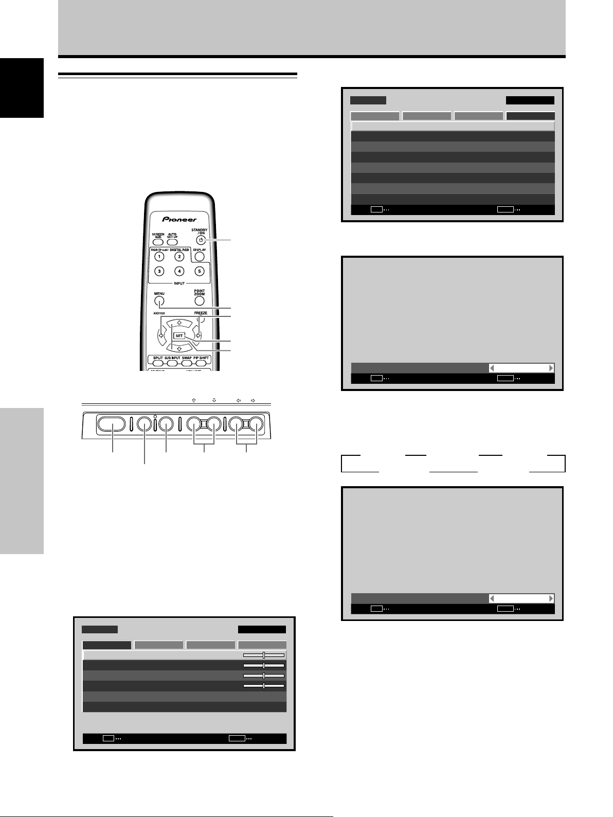
Menu display examples
MENU INPUT1
PICTURE
CONTRAST
BRIGHTNESS
H.ENHANCE
V.ENHANCE
PICTURE RESET
SET
Images shown here may differ from the actual display
image.
SCREEN SETUP OPTION
ENTER
:
:
:
:
MENU
0
0
0
0
EXIT
English
The remainder of the sections in this manual is dedicated
to the basic operations associated with selecting a source
component up to the more complex operations
associated with adjusting the Plasma Display picture to
match the requirements of specific components and
personal preferences.
Before Proceeding
3
En
Page 10
Before Proceeding
About operations in this manual
Each operation is described in its proper operating order.
English
These Operating Instructions will refer to the operating
controls found on the remote control unit, with the
exception of those buttons found only on the main
Plasma Display itself. When the Plasma Display controls
include equivalent buttons to those found on the remote
control unit, the commands can be performed on the
main unit as well.
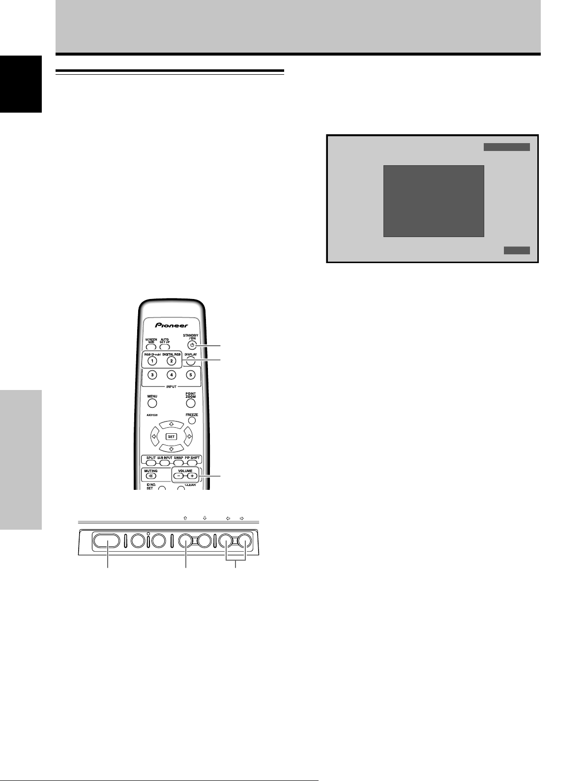
The following illustrations are an example of the actual
operations used for the section “PICTURE adjustment”.
The examples are provided to allow you to confirm
whether the operation is performed correctly or not.
Note
The screen images depicted in these Operating Instructions
should be considered typical images; some difference will be
seen in practice, depending on the screen item displayed and its
contents, the input source and various other control settings.
Before Proceeding
4
En
Page 11
Checking supplied accessories
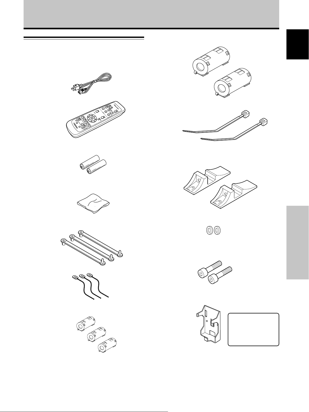
Check that the following accessories were supplied.
1 Power cord (2 m/6.6 feet)
Before Proceeding
8 Ferrite cores (x 2) (PDP-427CMX: for power cord)
English
2 Remote control unit
3 AA (R6) batteries (x 2)
4 Cleaning cloth (for screen)
5 Speed clamps (x 3)
9 Cable ties (x 2) (PDP-427CMX)
0 Display stands (x 2) (PDP-427CMX)
- Washers (x 2) (PDP-427CMX)
= Hex hole bolts (M8 x 40 mm) (x 2) (PDP-427CMX)
Before Proceeding
6 Bead bands (x 3)
7 Ferrite cores (x 3) (for audio cables)
~ Remote control unit holder (PDP-427CMX)
Use as a holder for the
remote control unit.
When attaching to the
rear of the main unit,
be careful not to cover
the vents.
÷ These Operating Instructions
÷ Warranty
5
En
Page 12
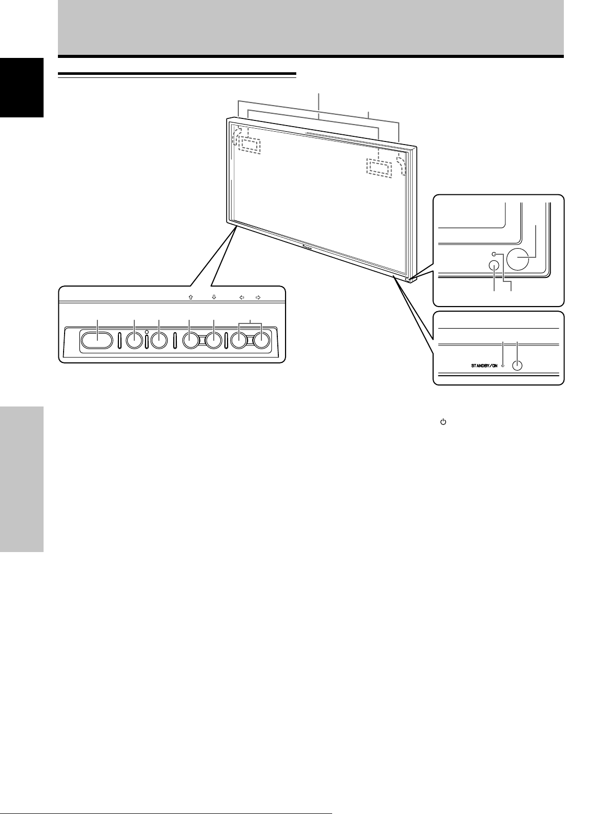
Part Names and Functions
Main unit
English
Main unit
Operation panel on the
main unit
(PDP-507CMX/PDP-427CMX)
4
(PDP-607CMX)
4
PDP-507CMX
PDP-427CMX
STANDBY
ON
1
STANDBY/ON MENU
DISPLAY
/ SET
6 7 8 95
Main unit
1 Remote control sensor
Point the remote control toward the remote sensor to
operate the unit (page 8).
2 Ambient light sensor (PDP-507CMX/PDP-427CMX)
This sensor measures the level of light inside the
viewing room; it is enabled when the [ENERGY
SAVE] option is set to [AUTO] (page 32).
3 STANDBY/ON indicator
Part Names and Functions
When the unit is operating:
The indicator lights green (page 20).
When flashing, the indicator is used to indicate error
messages (page 41).
The indicator flashes green once every one second
when the [POWER MGT.] function is operating (page
25).
When the unit is in standby mode:
The indicator lights red (page 20).
When flashing, the indicator is used to indicate error
messages (page 41).
4 Handles
– VOL +INPUT SCREEN SIZE
0
2
3
PDP-607CMX
13
Operation panel on the main unit
5 STANDBY/ON button ( )
Press to put the display in operation or standby mode
(page 20).
6 MENU button
Press to open and close the on-screen menu (pages
18 to 37).
7 DISPLAY/SET button
Use to confirm onscreen menu selections, and to
change settings (pages 18 to 37).
When not indicated by onscreen menus, used to
display the current set status (page 21).
8 INPUT (’) button
Except when menu screen is displayed, this button
operates to change the input.
9 SCREEN SIZE (‘) button
Except when menu screen is displayed, this button
operates to change the screen size.
0 VOL +/– (}/]) buttons
When not indicated for use in onscreen menu items,
these buttons are used for adjusting the sound
volume (pages 20 and 21).
6
En
Page 13
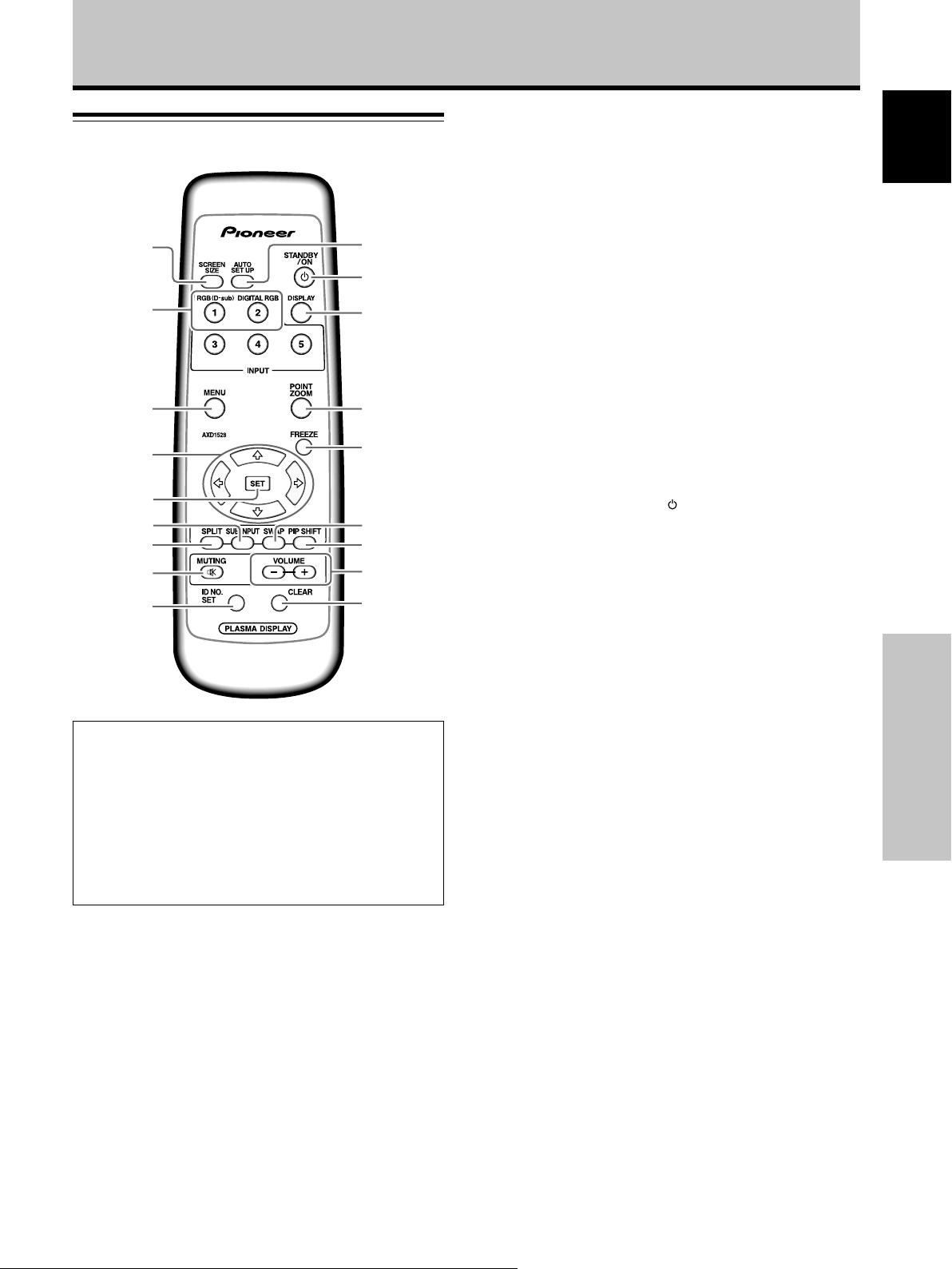
Remote control unit
1
0
-
Part Names and Functions
5 SET button
Press to adjust or enter various settings on the unit
(pages 18 to 37).
6 SUB INPUT button
During multi-screen display, use this button to change
inputs to subscreens (page 24).
7 SPLIT button
Press to switch to multi-screen display (page 24).
English
2
3
4
=
~
!
5
@6
7
8
9
When handling the remote control unit
¶ Do not drop the remote control unit or expose it to
moisture.
¶ Do not use the remote control unit in a location subject to
direct sunlight, heat radiation from a heater, or in a place
subject to excessive humidity.
¶ When the remote control unit’s batteries begin to wear out,
the operable distance will gradually become shorter. When
this occurs, replace all batteries with new ones as soon as
possible.
#
$
%
8 MUTING button
Press to mute the volume (page 21).
9 ID NO. SET button
Button used by professional installers.
0 AUTO SET UP button
When using computer signal input, automatically sets
the [POSITION], [CLOCK] and [PHASE] to optimum
values (page 27).
- STANDBY/ON button ( )
Press to put the unit in operation or standby mode
(page 20).
= DISPLAY button
Press to view the unit’s current input and setup mode
(page 21).
~ POINT ZOOM button
Use to select and enlarge one part of the screen (page
23).
! FREEZE button
When memo screen function is enabled, a still image
is displayed in the subscreen (page 37).
@ SWAP button
During multi-screen display, use this button to switch
between main screen and subscreen (page 24).
# PIP SHIFT button
When using the picture-in-picture mode with multiscreen display, use this button to move the position of
subscreen (page 24).
Part Names and Functions
1 SCREEN SIZE button
Press to select the screen size (page 22).
2 INPUT buttons
Press to select the input (page 20).
3 MENU button
Press to open and close the on-screen menu
(pages 18 to 37).
4 ADJUST (5/∞/3/2) buttons
Use to navigate menu screens and to adjust various
settings on the unit (pages 18 to 37).
$ VOLUME (+/–) buttons
Use to adjust the volume (pages 20 and 21).
% CLEAR button
Button used by professional installers.
7
En
Page 14
Part Names and Functions
English
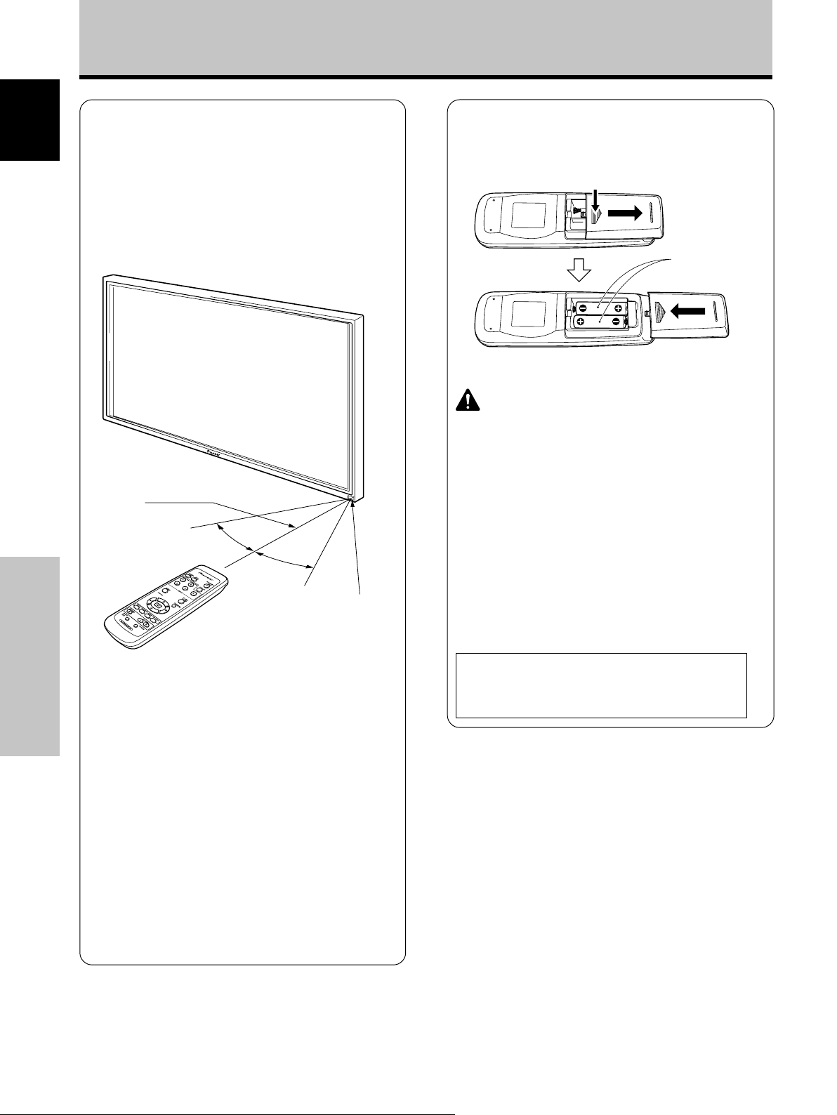
Operating range of the remote
control unit
When operating the remote control unit, point it at the
remote sensor located on the front panel of the main
unit. The remote control unit is operable up to 7 m from
the unit and within a 30 angle on each side of the
sensor.
7 m
(23 feet)
30°
30°
Remote Sensor
Inserting the batteries in the
remote control unit
While pressing down lightly, slide
in the direction of the arrow.
Two AA (R6)
batteries
Designated batteries
Please use size AA (R6) or AA (LR6).
CAUTION
¶ Do not use batteries other than those designated, and do
not mix old and new batteries together, since rupture or
leakage may result, leading to danger of fire, personal
injury, or contamination.
¶ When loading batteries into the remote control unit, insert
the batteries with (+) and (–) polarities matching those
indicated in the diagram. Inserting batteries incorrectly
may result in battery rupture or leakage, leading to danger
of fire, personal injury, or contamination.
¶ Do not heat or disassemble batteries, and do not dispose
of batteries in fire or water, since battery rupture or leakage
may result, leading to danger of fire or personal injury.
¶ When not using the remote control unit for extended
periods of time, remove the batteries and store them
separately. Leaving batteries unused in the unit may
result in battery leakage, leading to danger of fire,
personal injury, or contamination.
If you are having difficulty with operation of
the remote control unit
Part Names and Functions
¶ The remote control unit may not operate if there are
objects placed between it and the display.
¶ Operational distance will gradually become shorter as the
batteries begin to wear out, replace weak batteries with
new ones as soon as possible.
¶ This unit discharges infrared rays from the screen. Placing a
video deck or other component that is operated by an
infrared remote control unit near this unit may hamper that
component’s reception of the remote control’s signal, or
prevent it from receiving the signal entirely. Should this
occur, move the component to a position further away from
this unit.
¶ Depending on the installation surroundings, this unit’s
remote control unit may be influenced by the infrared rays
discharged from the Plasma Display, hampering reception
of its rays or limiting its operational distance. The strength
of infrared rays discharged from the screen will differ
according to the picture displayed.
When disposing of used batteries, please comply
with governmental regulations or
environmental public institution’s rules that
apply in your country/area.
D3-4-2-3-1_En
8
En
Page 15
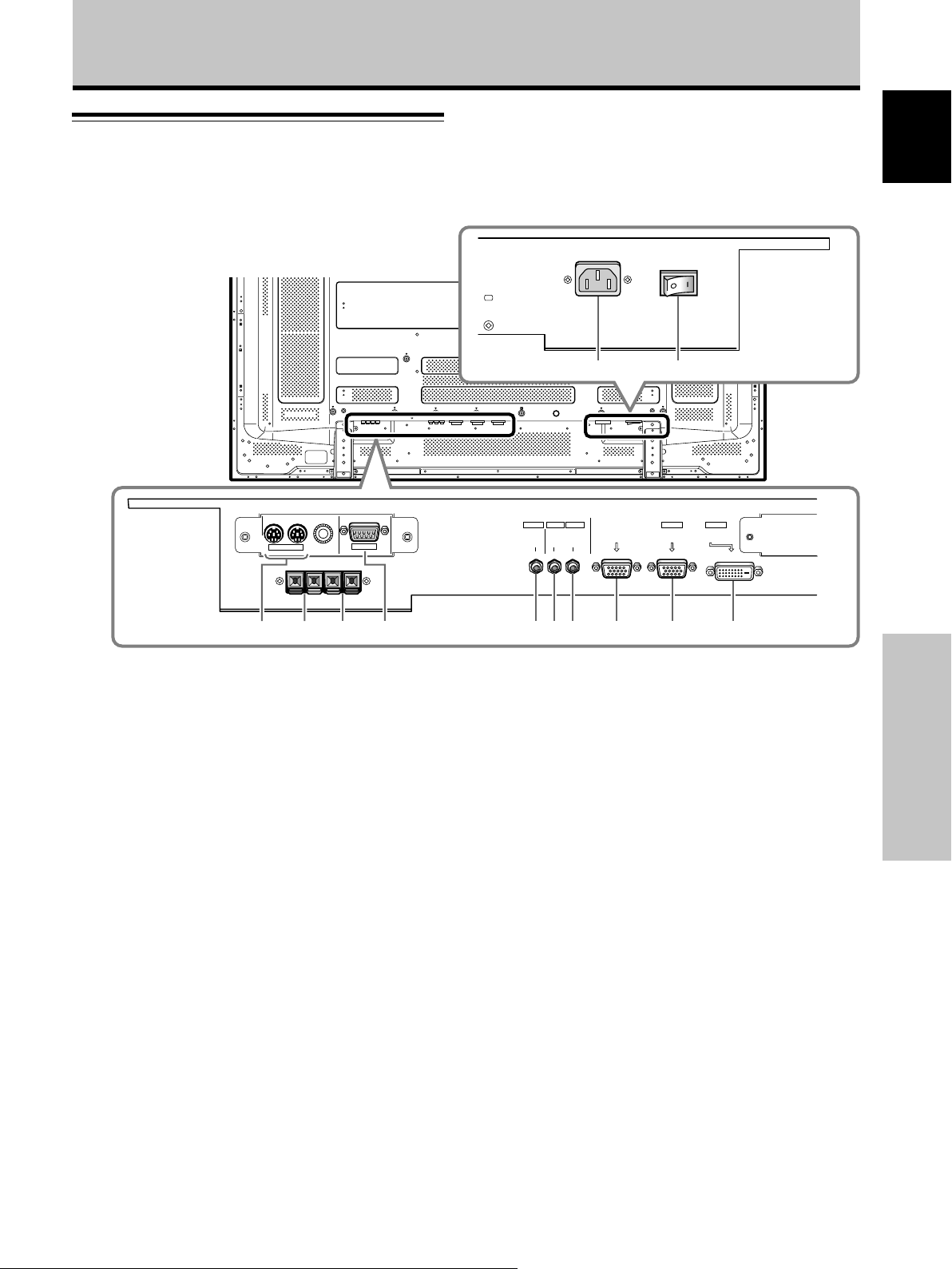
Part Names and Functions
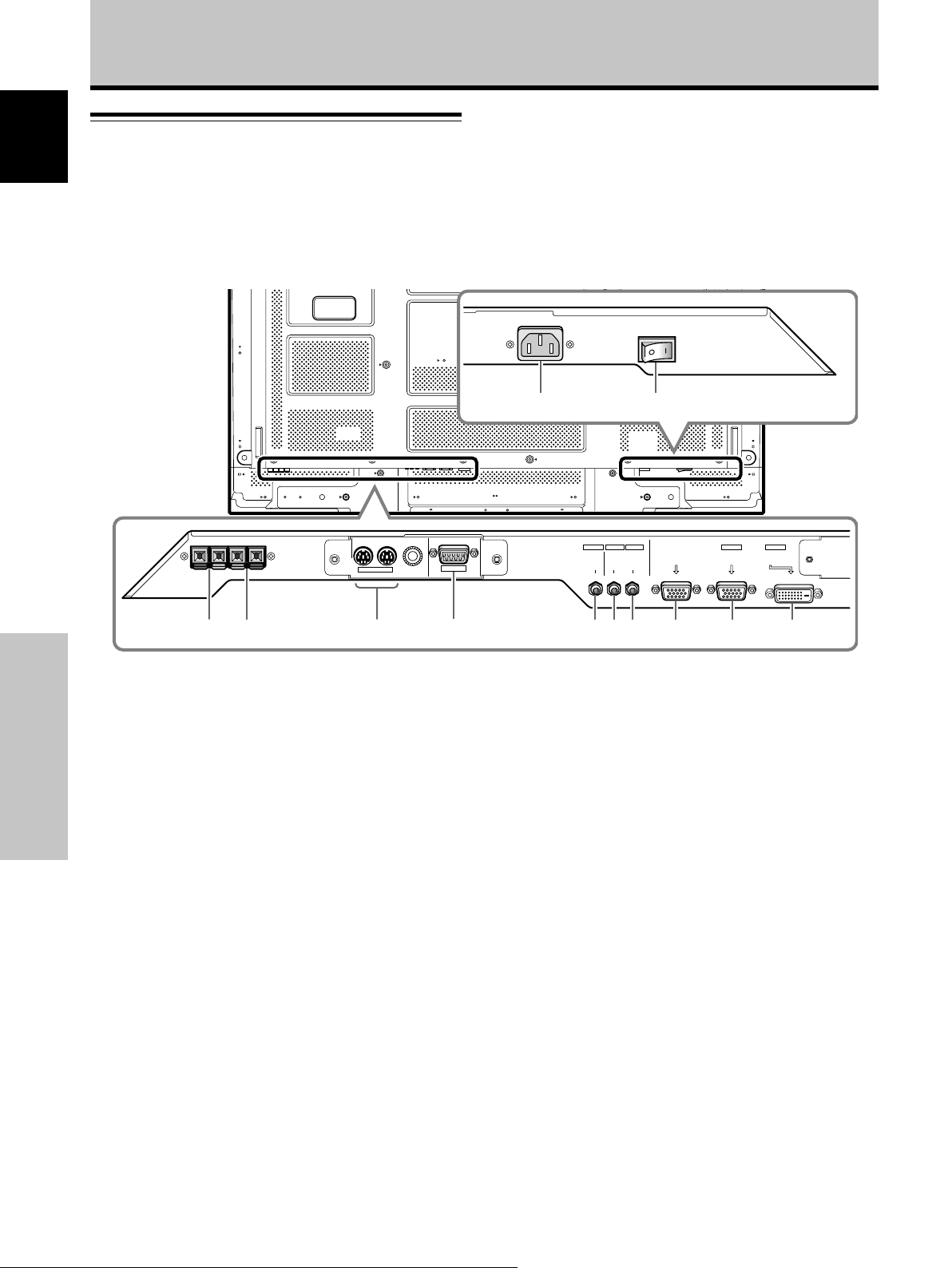
Connection panel (PDP-607CMX)
The connection panel is provided with two video input
terminals and one video output terminal. Audio input/
output and speaker output terminals are also provided.
For instructions regarding connections, consult the pages
noted in parentheses by each item.
IN OUT
COMBINATION
RS-232C
INPUT1
OUTPUT INPUT2
AUDIO
AUDIO AUDIO
ANALOG RGB OUT
(D-Sub)
=-
INPUT1
ANALOG RGB IN
(D-Sub)
INPUT2
DIGITAL RGB
(DVI-D)
English
1 COMBINATION IN/OUT
Never connect any component to these
connectors without first consulting your Pioneer
installation technician.
These connectors are used for Plasma Display setup
adjustments.
2 SPEAKER (R) terminal
For connection of an external right speaker.
Connect a speaker that has an impedance of 6 Ω to
16 Ω (page 15).
3 SPEAKER (L) terminal
For connection of an external left speaker. Connect a
speaker that has an impedance of 6 Ω to 16 Ω (page
15).
4 RS-232C
Never connect any component to this connector
without first consulting your Pioneer installation
technician.
This connector is used for Plasma Display setup
adjustments.
5 AUDIO (OUTPUT) (Stereo mini jack)
Use to output the audio of the selected source
component connected to this unit to an AV amplifier
or similar component.
Note: No sound is produced from the AUDIO (OUTPUT) jack
when the MAIN POWER switch is set to OFF or ON (standby)
(page 15).
0432158967
6 AUDIO (INPUT1) (Stereo mini jack)
Use to obtain sound when INPUT1 is selected.
Connect the audio output jack of components
connected to INPUT1 to this unit (page 15).
7 AUDIO (INPUT2) (Stereo mini jack)
Use to obtain sound when INPUT2 is selected.
Connect the audio output jack of components
connected to INPUT2 to this unit (page 15).
8 ANALOG RGB OUT (INPUT1) (mini D-sub 15 pin)
Use the ANALOG RGB OUT (INPUT1) terminal to
output the video signal to an external monitor or other
component.
Note: The video signal will not be output from the ANALOG
RGB OUT (INPUT1) terminal when the main power of this
unit is off or in standby mode (page 14).
9 ANALOG RGB IN (INPUT1) (mini D-sub 15 pin)
For connection of a personal computer (PC) or similar
component. Make sure that the connection made
corresponds to the format of the signal output from
the connected component (page 14).
0 DIGITAL RGB (INPUT2) (DVI-D jack)
Use to connect a computer.
Note: This unit does not support the display of
copyguard-protected video signals (page 14).
- AC IN
Use to connect the supplied power cord to an AC
outlet (page 16).
= MAIN POWER switch
Use to switch the main power of the unit on and off.
Part Names and Functions
9
En
Page 16
Part Names and Functions
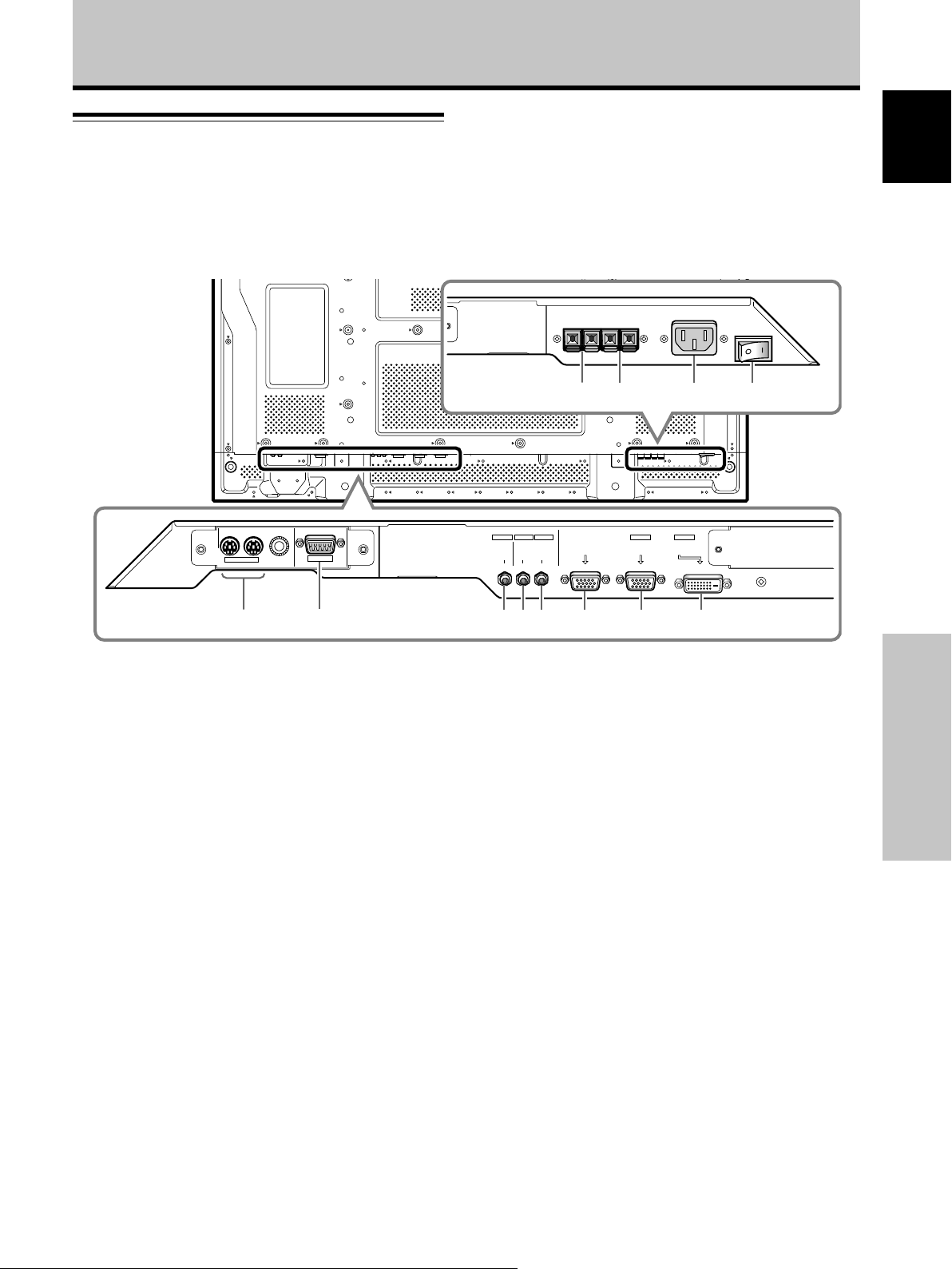
Connection panel (PDP-507CMX)
English
The connection panel is provided with two video input
terminals and one video output terminal. Audio input/
output and speaker output terminals are also provided.
For instructions regarding connections, consult the pages
noted in parentheses by each item.
=-
21 8 9 03567
1 SPEAKER (R) terminal
For connection of an external right speaker.
Connect a speaker that has an impedance of 6 Ω to
16 Ω (page 15).
2 SPEAKER (L) terminal
For connection of an external left speaker. Connect a
speaker that has an impedance of 6 Ω to 16 Ω (page
Part Names and Functions
15).
3 COMBINATION IN/OUT
Never connect any component to these
connectors without first consulting your Pioneer
installation technician.
These connectors are used for Plasma Display setup
adjustments.
4 RS-232C
Never connect any component to this connector
without first consulting your Pioneer installation
technician.
This connector is used for Plasma Display setup
adjustments.
5 AUDIO (OUTPUT) (Stereo mini jack)
Use to output the audio of the selected source
component connected to this unit to an AV amplifier
or similar component.
Note: No sound is produced from the AUDIO (OUTPUT) jack
when the MAIN POWER switch is set to OFF or ON (standby)
(page 15).
10
En
IN OUT
COMBINATION
RS-232C
4
INPUT1
OUTPUT INPUT2
AUDIO
AUDIO AUDIO
ANALOG RGB OUT
(D-Sub)
INPUT1
ANALOG RGB IN
(D-Sub)
INPUT2
DIGITAL RGB
(DVI-D)
6 AUDIO (INPUT1) (Stereo mini jack)
Use to obtain sound when INPUT1 is selected.
Connect the audio output jack of components
connected to INPUT1 to this unit (page 15).
7 AUDIO (INPUT2) (Stereo mini jack)
Use to obtain sound when INPUT2 is selected.
Connect the audio output jack of components
connected to INPUT2 to this unit (page 15).
8 ANALOG RGB OUT (INPUT1) (mini D-sub 15 pin)
Use the ANALOG RGB OUT (INPUT1) terminal to
output the video signal to an external monitor or other
component.
Note: The video signal will not be output from the ANALOG
RGB OUT (INPUT1) terminal when the main power of this
unit is off or in standby mode (page 14).
9 ANALOG RGB IN (INPUT1) (mini D-sub 15 pin)
For connection of a personal computer (PC) or similar
component. Make sure that the connection made
corresponds to the format of the signal output from
the connected component (page 14).
0 DIGITAL RGB (INPUT2) (DVI-D jack)
Use to connect a computer.
Note: This unit does not support the display of
copyguard-protected video signals (page 14).
- AC IN
Use to connect the supplied power cord to an AC
outlet (page 16).
= MAIN POWER switch
Use to switch the main power of the unit on and off.
Page 17
Part Names and Functions
Connection panel (PDP-427CMX)
The connection panel is provided with two video input
terminals and one video output terminal. Audio input/
output and speaker output terminals are also provided.
For instructions regarding connections, consult the pages
noted in parentheses by each item.
IN OUT
COMBINATION
RS-232C
INPUT1
OUTPUT INPUT2
AUDIO
AUDIO AUDIO
ANALOG RGB OUT
(D-Sub)
INPUT1
ANALOG RGB IN
(D-Sub)
INPUT2
DIGITAL RGB
(DVI-D)
English
=-09
13
2
1 COMBINATION IN/OUT
Never connect any component to these
connectors without first consulting your Pioneer
installation technician.
These connectors are used for Plasma Display setup
adjustments.
2 RS-232C
Never connect any component to this connector
without first consulting your Pioneer installation
technician.
This connector is used for Plasma Display setup
adjustments.
3 AUDIO (OUTPUT) (Stereo mini jack)
Use to output the audio of the selected source
component connected to this unit to an AV amplifier
or similar component.
Note: No sound is produced from the AUDIO (OUTPUT) jack
when the MAIN POWER switch is set to OFF or ON (standby)
(page 15).
4 AUDIO (INPUT1) (Stereo mini jack)
Use to obtain sound when INPUT1 is selected.
Connect the audio output jack of components
connected to INPUT1 to this unit (page 15).
5 AUDIO (INPUT2) (Stereo mini jack)
Use to obtain sound when INPUT2 is selected.
Connect the audio output jack of components
connected to INPUT2 to this unit (page 15).
6 7 845
6 ANALOG RGB OUT (INPUT1) (mini D-sub 15 pin)
Use the ANALOG RGB OUT (INPUT1) terminal to
output the video signal to an external monitor or other
component.
Note: The video signal will not be output from the ANALOG
RGB OUT (INPUT1) terminal when the main power of this
unit is off or in standby mode (page 14).
7 ANALOG RGB IN (INPUT1) (mini D-sub 15 pin)
For connection of a personal computer (PC) or similar
component. Make sure that the connection made
corresponds to the format of the signal output from
the connected component (page 14).
8 DIGITAL RGB (INPUT2) (DVI-D jack)
Use to connect a computer.
Note: This unit does not support the display of
copyguard-protected video signals (page 14).
9 SPEAKER (R) terminal
For connection of an external right speaker.
Connect a speaker that has an impedance of 6 Ω to
16 Ω (page 15).
0 SPEAKER (L) terminal
For connection of an external left speaker. Connect a
speaker that has an impedance of 6 Ω to 16 Ω (page 15).
- AC IN
Use to connect the supplied power cord to an AC
outlet (page 16).
= MAIN POWER switch
Use to switch the main power of the unit on and off.
Part Names and Functions
11
En
Page 18
Installation and Connections
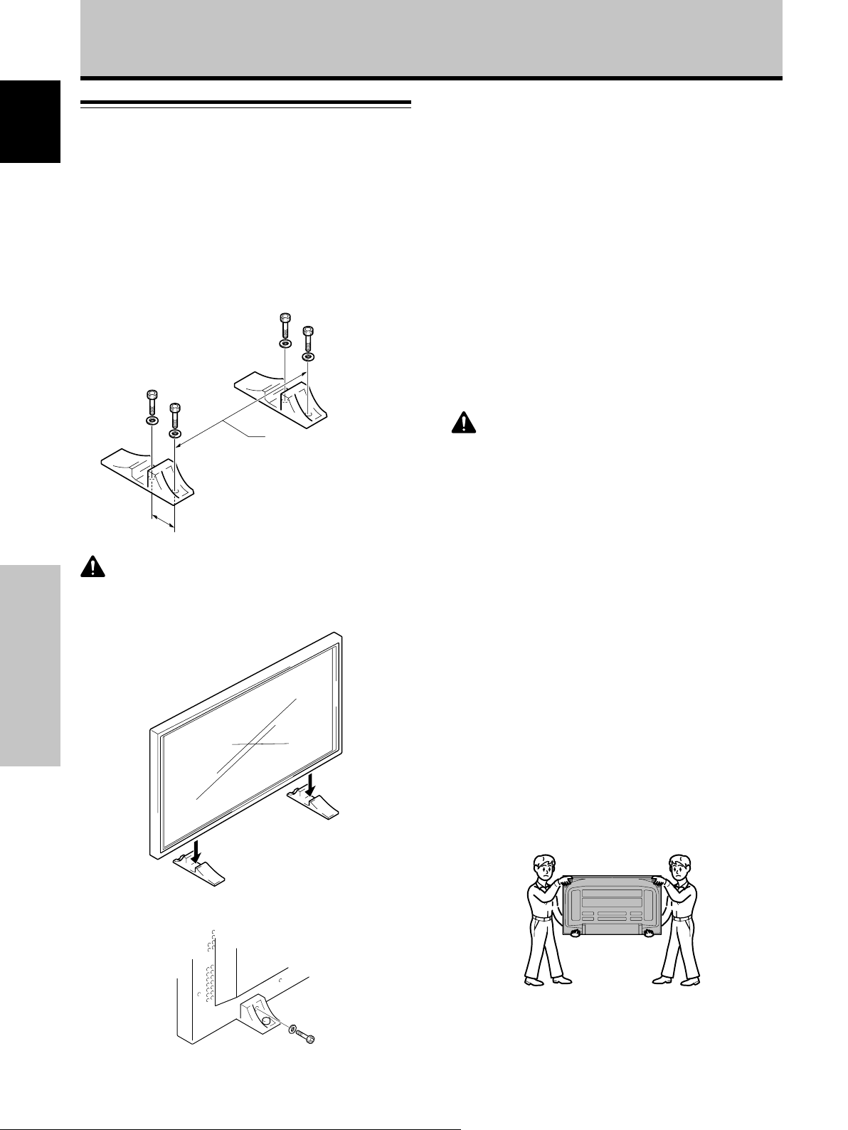
Installation of the unit
English
Installation using the supplied display stands
(PDP-427CMX)
Be sure to fix the supplied stands to the installation surface.
Use commercially available M8 bolts that are 25 mm
(1 in.) longer than the thickness of the installation surface.
Installation using the optional PIONEER stand or
other mounting brackets
÷ Please be sure to request installation or mounting of this unit
by an installation specialist or the dealer where purchased.
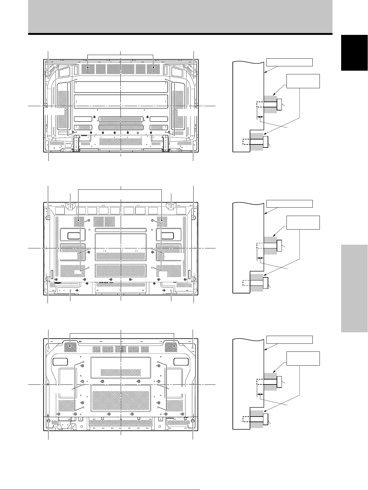
Wall-mount installation of the unit
This unit has been designed with bolt holes for
wall-mount installation, etc. The installation holes
provided are shown in the accompanying illustration.
1 Fix the supplied stands to the installation surface
at each of the 4 prepared holes using
commercially available M8 bolts.
Front
517 mm (20-3/8 in.)
(Bolt hole thread pitch)
Rear
Always install the supplied display
stands according to the dimensions
shown in the accompanying
illustration.
110 mm (4-5/16 in.)
CAUTION
Please be sure to use an M8 (Pitch = 1.25 mm) bolt. (Only this
size bolt can be used.)
2 Set this unit in the stands.
Installation and Connections
÷ Be sure to attach in 4 or more locations above and
below, left and right of the center line.
÷ Use bolts that are long enough to be inserted 12 mm
1
(
/2 in.) to 18 mm (11/16 in.) into the main unit from the
attaching surface for a holes. Refer to the side view
diagram in the accompanying illustration.
÷ As this unit is constructed with glass, be sure to install
it on a flat, unwarped surface.
CAUTION
÷ Use only those stands or mounting brackets designated by
Pioneer. If other non-recommended products are used, the
unit may fall and be damaged or otherwise malfunction.
÷ Assemble stands or mounting brackets correctly in accordance
with the instructions provided or other applicable installation
instructions.
÷ Two or more people should always work together when
installing or removing this unit.
÷ The installation location selected should be fully capable of
supporting the weight of this unit, and be a stable, flat, and
even surface. If installed in other locations, the unit may fall or
be damage.
÷ After installation, take appropriate measures to prevent the
installation from falling. The failure to take such measures
could allow the unit to fall, causing injuries or damage.
÷ When this unit is installed on a wall, the work should be done
by a professional technician possessing the requisite technical
knowledge and abilities; consult your dealer for more
information. Improper or insufficient installation may result in
accidents, damage or personal injury.
÷ Handles should not be removed or reattached by anyone other
than the professional installation technician or service
personnel.
÷ When moving the display, it should always be carried by two
persons holding the rear handles in the manner shown.
Never attempt to move the Plasma Display by holding only
one of the handles.
3 Fix this unit using the supplied washers and hex
hole bolts.
Use a 6 mm (1/4 in.) hex
wrench to bolt them.
12
En
Page 19
Installation and Connections
b hole*
a hole
b hole*
b hole*
Air vents (fan)
Center line
Rear view diagram (PDP-607CMX)
Air vents (fan)
a hole
a hole
a hole
a hole
b hole*
a hole
b hole*
b hole*
Center line
Center line
Attaching surface
Main unit
b hole
a hole
Bolt
12 mm to 18 mm
(1/2 in. to 11/16 in.)
Screw provided with
speaker unit (sold
separately)
Side view diagram
Attaching surface
Main unit
a hole
Bolt
English
Installation
bracket, etc.
Français
Installation
bracket, etc.
a hole
Rear view diagram (PDP-507CMX)
b hole*
a hole
Rear view diagram (PDP-427CMX)
* Only for speaker unit
Center line
Air vents (fan)
Center line
a hole
a hole
b hole*b hole*
b hole*
b hole*b hole*
Center line
12 mm to 18 mm
(1/2 in. to 11/16 in.)
b hole
Screw provided with
speaker unit (sold
separately)
Side view diagram
Attaching surface
Main unit
b hole
a hole
Bolt
12 mm to 18 mm
(1/2 in. to 11/16 in.)
Screw provided with
speaker unit (sold
separately)
Side view diagram
Installation and Connections
Installation
bracket, etc.
13
En
Page 20
Installation and Connections
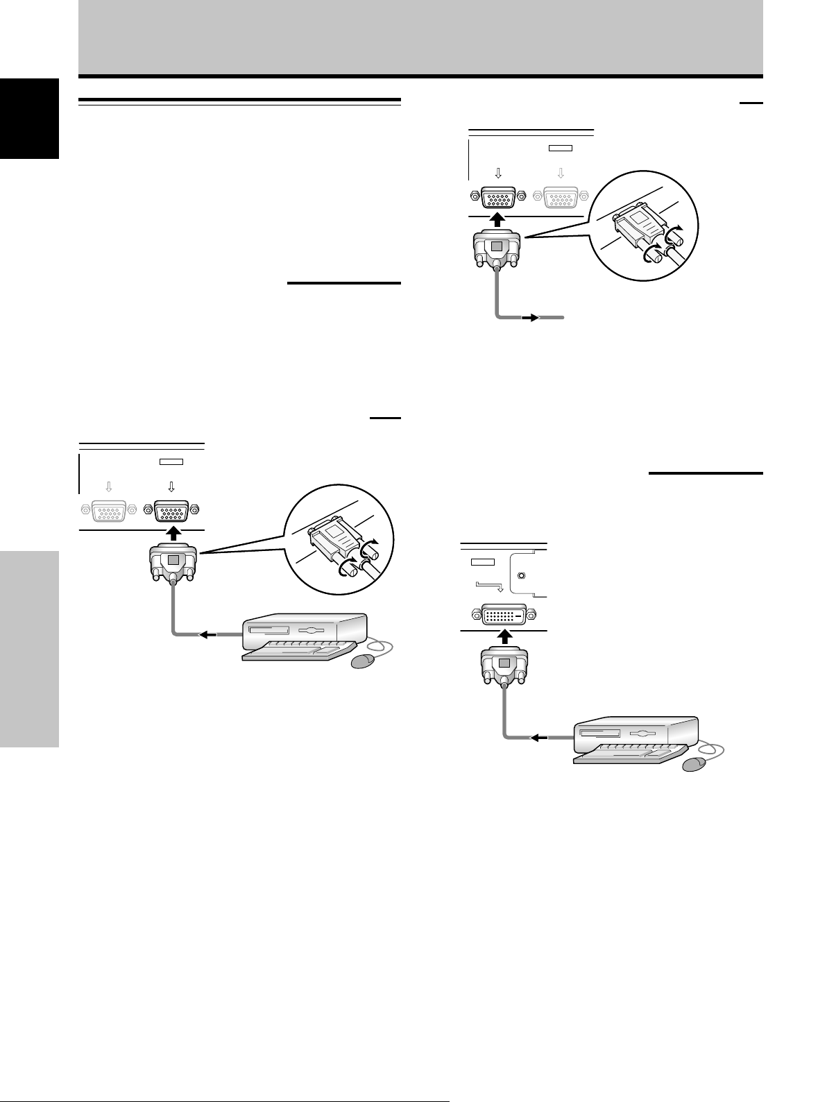
Connection to a personal computer
English
Connection method differs depending on the computer
type. When connecting, please thoroughly read the
computer’s instruction manual.
Before making connections, be sure to make sure that
the personal computer’s power and this unit’s main
power is off.
Connection to INPUT1
When connecting to ANALOG RGB OUT (INPUT1)
ANALOG RGB OUT
(D-Sub)
INPUT1
ANALOG RGB IN
(D-Sub)
Connect the display’s D-sub input connector to the D-sub
output (analog RGB) from the computer.
This connector also supports G ON SYNC (output with
green signal combined with sync signal), and composite
SYNC (output with combined horizontal and vertical sync
signals).
When connecting to ANALOG RGB IN (INPUT1)
ANALOG RGB OUT
(D-Sub)
INPUT1
ANALOG RGB IN
(D-Sub)
Connect the cable corresponding to the shape of the
input terminal on this unit and the personal computer’s
Installation and Connections
output terminal.
Secure by tightening the terminal screws on both units.
To an external monitor
With this unit, it is possible to output the video signal to
an external monitor or other component from the
ANALOG RGB OUT (INPUT1) terminal.
Note
A video signal will not be output from the ANALOG RGB OUT
(INPUT1) terminal when the main power of this unit is off or in
standby.
Connection to INPUT2
A computer equipped with DVI output (digital RGB signal)
can be connected to the Plasma Display’s DVI connector.
INPUT2
DIGITAL RGB
(DVI-D)
Following completing connections, on-screen setup is
necessary. See pages 18 to 19 for details.
Note
Depending on the type of computer model being connected, a
conversion connector or adapter etc. provided with the computer
or sold separately may be necessary.
For details, please read your PC’s instruction manual or consult
the maker or nearest dealer of your computer.
NOTICE
¶ INPUT1 supports Microsoft “Plug & Play” (VESA DDC 1/2B)
components. See Appendix 2-1/2 (page 49) when making
connections to INPUT1.
¶ See Appendix 1-1/4, -3/4 (pages 43 and 46) for information
regarding signals and display formats supported by INPUT1.
14
En
Following completing connections, on-screen setup is
necessary. See pages 18 to 19 for details.
Notes
¶ Use a DVI-D 24-pin (digital only) cable for the connection.
¶ This unit does not support the display of copyguard-protected
video signals.
NOTICE
¶ INPUT2 supports Microsoft “Plug & Play” (VESA DDC 2B)
components. See Appendix 2-2/2 (page 49) when making
connections to INPUT2.
¶ See Appendix 1-2/4, -4/4 (pages 44 and 47) for information
regarding signals and display formats supported by INPUT2.
Page 21
Installation and Connections
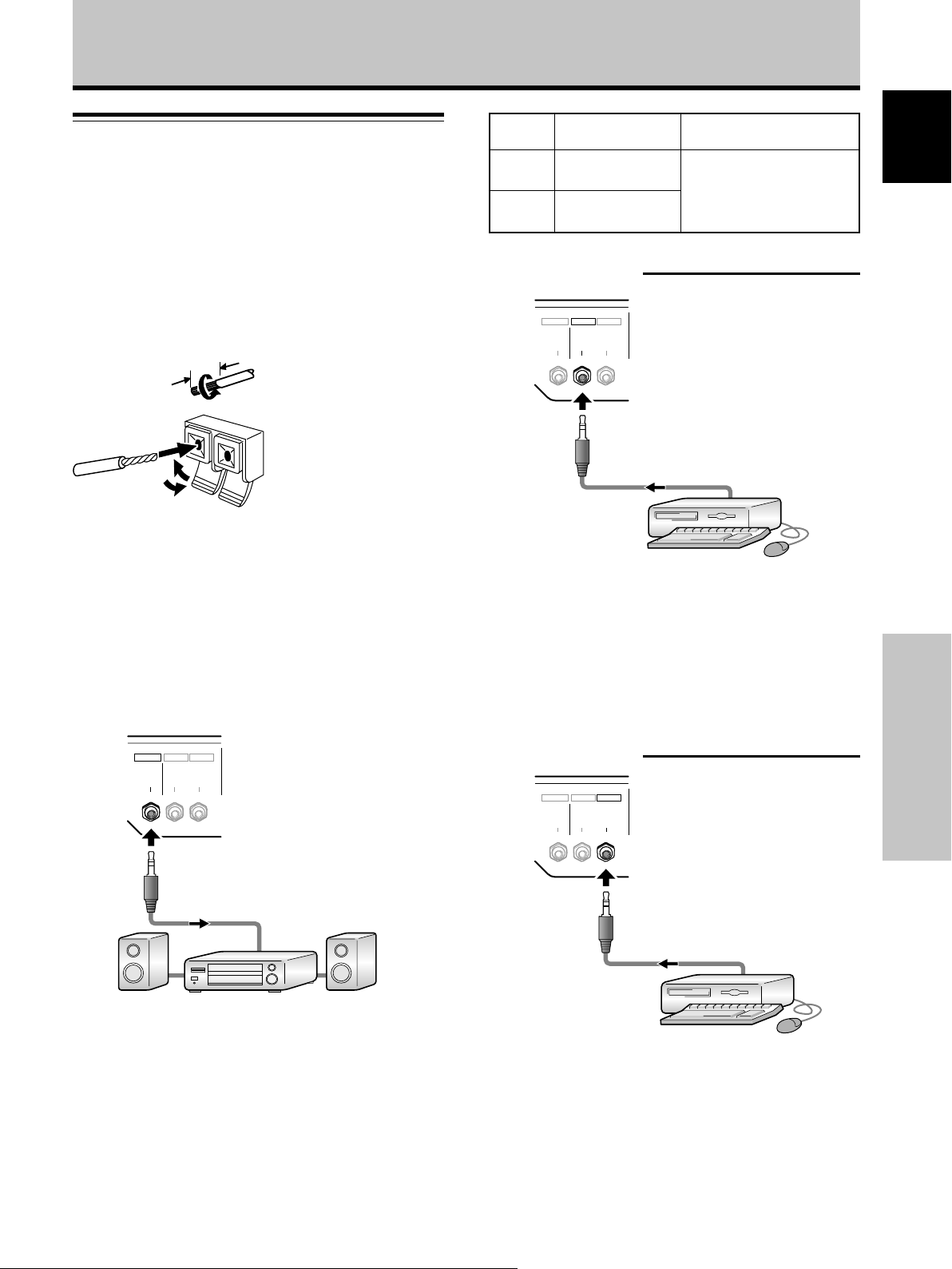
Audio connections
Before making connections, be sure to check that the
audio component’s power and the unit’s main power is
off.
Connecting the speakers
This unit is equipped with speaker output terminals for
connection to the speaker system (not supplied) specially
designed for use with this unit. Refer to the illustrations
below when making connections to the speaker terminals
on this unit.
Notes
÷ After connecting the wires, pull gently on the cords to confirm
that the wire cores are fastened securely in their terminals.
Insecure connections will result in noise or interrupted sound.
÷ Do not allow the wire cores of the ª and · speaker cords to
protrude excessively, since they may touch each other,
causing a short circuit. This will produce excessive load on the
Plasma Display, causing operation to malfunction or stop.
Connection to audio output connector
Use a stereo miniplug to connect the Plasma Display’s
AUDIO (OUTPUT) stereo mini jack (L/R) to an AV amplifier
or other component.
OUTPUT INPUT2
AUDIO
12 mm
INPUT1
AUDIO AUDIO
Twist exposed
wire strands
together.
Push tab to the open
position, and insert the
wire. Then, close tab
firmly to secure the wire
in place.
Video
input
INPUT1
INPUT2
Audio input jacks Sound output
Stereo mini jack
(L/R)
Stereo mini jack
(L/R)
Sound of the selected video
input is output from the
• SPEAKER (L/R) terminals
• Stereo mini jack (L/R)
Audio connections for component (computer)
connected to INPUT1
INPUT1
OUTPUT INPUT2
AUDIO
AUDIO AUDIO
A stereo miniplug cable can be used to connect the audio
output from the component connected to INPUT1, to the
Plasma Display’s AUDIO (INPUT1) stereo mini jack (L/R).
Sound is output from both the AUDIO (OUTPUT) stereo
mini jack (L/R) and the SPEAKER (L/R) terminals according
to the video input selection.
Audio connections for component (computer)
connected to INPUT2
INPUT1
OUTPUT INPUT2
AUDIO
AUDIO AUDIO
English
Français
Installation and Connections
Making connections to the audio inputs on this
unit
This unit features two audio inputs and one audio output.
The following chart shows the video inputs and the
corresponding audio input terminals.
A stereo miniplug cable can be used to connect the audio
output from the component connected to INPUT2, to the
Plasma Display’s AUDIO (INPUT2) stereo mini jack (L/R).
Sound is output from both the AUDIO (OUTPUT) stereo
mini jack (L/R) and the SPEAKER (L/R) terminals according
to the video input selection.
15
En
Page 22
Installation and Connections
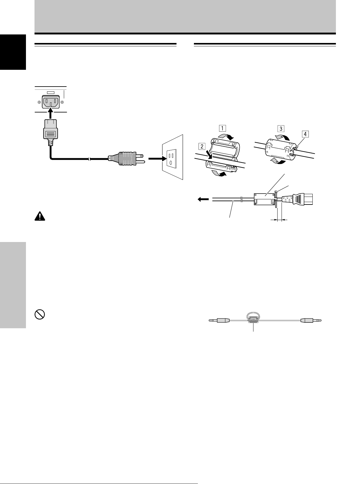
Power cord connection
English
Connect the power cord after all component connections
have been completed.
AC IN
1
2
1 Connect the power cord to this unit.
2 Plug the power cord into a power outlet.
CAUTION
÷ Use only the power cord provided.
÷ The wall outlet used to provide electricity to this unit should be
as close as possible to the unit and within easy reach of the
user.
In the event that it is necessary to disconnect power to the
unit, first turn off the main unit’s power switch, and then
disconnect the power cord from its wall outlet.
÷ For the Plasma Display, use a three-core power cord with a
ground terminal.
Always be sure to connect the power cord to a three-pronged
grounded outlet and make sure that the cord is properly
grounded. If you use a power source converter plug, use an
outlet with a ground terminal and screw down the ground line.
Attaching the ferrite cores
Power cord (PDP-427CMX)
Attach the accessory ferrite cores to the both connector
ends of the power cord as shown in the accompanying
illustration. Use the provided cable tie to prevent the
ferrite core from slipping on the cable.
If you do not do this, this monitor will not conform to
mandatory FCC standards.
Ferrite core
Cable tie
To power
outlet
AC power cord
As close as possible
Audio cable
Regarding the audio cable, attach the supplied ferrite
core.
Wind the audio cable (not supplied) around the ferrite
core once, and then fasten the catch.
If you do not do this, this monitor will not conform to
mandatory FCC standards.
Audio cable (not supplied)
To AC IN
Installation and Connections
NO!
Do not use a power supply voltage other than that indicated (AC
100 V to 120 V, 50 Hz/60 Hz) as this may cause fire or electric
shock.
16
En
Ferrite core
Page 23
Installation and Connections
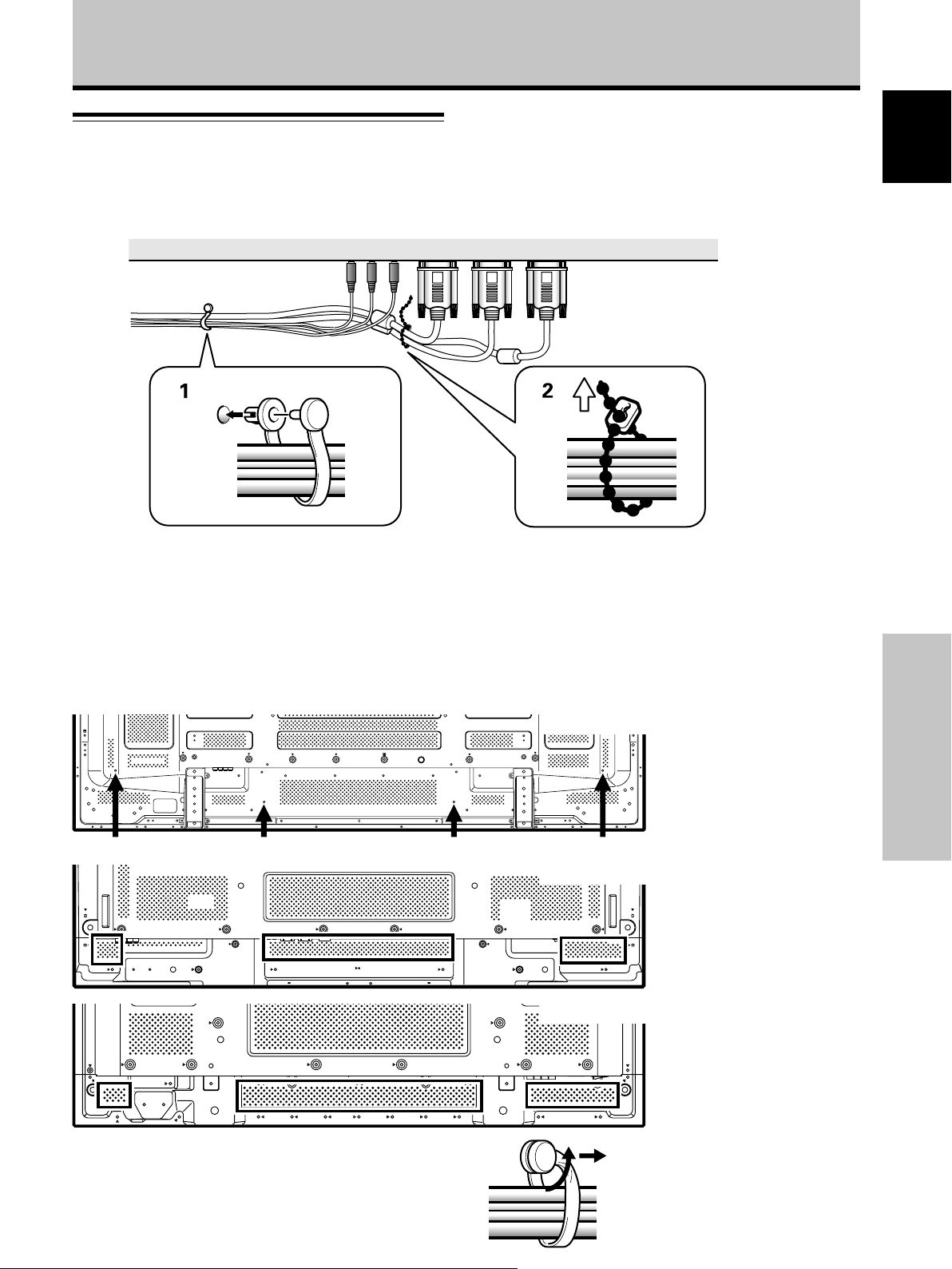
How to route cables
Speed clamps are included with this unit for bunching
cables together. Once components are connected, follow
the following steps to route cables.
2
1
1 Organize cables together using the provided
speed clamps.
Insert 1 into an appropriate hole on the rear of the
unit, then snap 2 into the back of 1 to fix the clamp.
Speed clamps are designed to be difficult to undo
once in place. Please attach carefully.
To attach the speed clamps to the main unit
Connect the speed clamps using the 4 holes marked with “‡” below, depending on the situation.
* As viewed from the rear of the display.
2 Bunch separated cables together and secure them
with the provided bead bands.
Do not allow excessive stress to be placed on the
ends of cables.
Note
Cables can be routed to the right or left.
PDP-607CMX
English
Français
Use the holes marked with the & sign as needed.
To remove speed clamps
Using pliers, twist the clamp 90° and pull it outward.
In some cases the clamp may have deteriorated over
time and may get damaged when removed.
Installation and Connections
PDP-507CMX
PDP-427CMX
* As viewed from the rear of the
display.
17
En
Page 24
System Settings
Setting the onscreen display
English
language
The onscreen display language has been set to English as
the factory default. To change to another language, the
screen setting must be changed. Follow the procedures
below to change the setting.
4 Use the 2/3 buttons to select [OPTION].
MENU INPUT1
PICTURE
LANGUAGE
ENERGY SAVE
TIMER SETTING
SCREEN MGT.
AUTO SETUP MODE
AUTO FUNCTION
PIP DETECT
SPLIT FREEZE
SET
SCREEN SETUP OPTION
ENTER
:ENGLISH
:STANDARD
:INACTIVE
:OFF
:ACTIVE
:OFF
MENU
EXIT
Remote control unit
STANDBY/ON MENU
DISPLAY
/ SET
SET 5/∞
MENU
Main unit operating panel
System Settings
1 Set the rear panel MAIN POWER switch to ON.
The STANDBY/ON indicator on the front panel will
light red.
2 Press the STANDBY/ON button to turn the power
ON.
The STANDBY/ON indicator on the front panel will
light green.
3 Press the MENU button to display the menu
screen.
STANDBY/
ON
MENU
2/3
SET
5/∞
– VOL +INPUT SCREEN SIZE
2/3STANDBY/ON
5 Use the 5/∞ buttons to select [LANGUAGE], then
press the SET button.
LANGUAGE ENGLISH
SET
SET
6
Use the 2/3 buttons to select the desired language.
Each time the 2/3 buttons are pressed, the language
alternates between those available, in the following
order:
3
ENGLISH
LANGUAGE ENGLISH
2
3 ITALIANO 2
SET
SET
3
FRANÇAIS
:
MENU
2 3
ESPAÑOL
3 DEUTSCH 2
:
MENU
EXIT
2
EXIT
MENU INPUT1
PICTURE
CONTRAST
BRIGHTNESS
H.ENHANCE
V.ENHANCE
PICTURE RESET
SET
SCREEN SETUP OPTION
ENTER
18
En
7 With the desired language displayed, press the
:
0
:
0
:
0
:
0
SET button.
The selected language will be set in memory, and the
screen will return to that shown in step 4.
8 When settings are completed, press the MENU
button to return to the normal screen image.
Note
MENU
EXIT
When the onscreen display language is set for either INPUT1 or
INPUT2, the display language for the other input will be set to
the same language.
Page 25

Settings after connections
After components have been connected to INPUT1 or
INPUT2, on-screen setup is necessary.
Follow the procedure described below and make settings
as they apply to the type of components connected.
[SIGNAL FORMAT] setup
System Settings
3 Use the 5/∞ buttons to select [SIGNAL FORMAT],
then press the SET button.
MENU INPUT1
PICTURE
POWER MGT. :OFF
SIGNAL FORMAT
SCREEN SETUP OPTION
English
MENU
2/3
SET
5/∞
Remote control unit
STANDBY/ON MENU
DISPLAY
/ SET
– VOL +INPUT SCREEN SIZE
2/3MENU SET 5/∞
Main unit operating panel
1 Press the MENU button to display the menu
screen.
SET
CHANGE
MENU
EXIT
4 Use the 2/3 buttons to select the input signal.
SIGNAL FORMAT
SET
Each time the 2/3 buttons are pressed, the selection
alternates as follows:
÷ AUTO .... Signals are detected automatically in
÷ Others ... Selectable resolutions are displayed.
AUTO
:
SET
MENU
3 AUTO
Others 2
accordance with the Computer signal
compatibility table (pages 43 to 48)
EXIT
System Settings
MENU INPUT1
PICTURE
CONTRAST
BRIGHTNESS
H.ENHANCE
V.ENHANCE
PICTURE RESET
SET
SCREEN SETUP OPTION
ENTER
:
:
:
:
MENU
0
0
0
0
2 Use the 2/3 buttons to select [SETUP].
MENU INPUT1
PICTURE
POWER MGT. :OFF
SIGNAL FORMAT
SCREEN SETUP OPTION
5 Press the SET button.
The setting is stored in memory and the screen
returns to that shown in step 3.
6 When the setup is completed, press the MENU
button to exit the menu screen.
Note
Make [SIGNAL FORMAT] setting for each input (INPUT1 and
INPUT2).
EXIT
19
En
Page 26
Operation
Selecting input source
English
This section explains the basic operation of this unit.
Outlined on the following pages is how to turn the main
power on and off, put this unit in the operation or standby
mode and how to select connected components.
3 Press the INPUT button to select the input.
÷ When the menu screen is displayed, changing the
signal input will cause the menu screen to turn off.
÷ If the input computer signal is not supported by the
display, the following message will be displayed:
INPUT1
Before you begin, make sure you have:
÷ Made connections between this unit and personal
computer as described in the section “Installation and
Connections” starting on page 12.
÷ Set up the on-screen menu to input signals from
components connected to INPUT1 and INPUT2 as
described in the section “System Settings” starting on
page 18.
If no connections are made to these terminals,
on-screen setup is not necessary.
Operation
STANDBY/
ON
INPUT
VOLUME
[+/–]
CAUTION
UNSUPPORTED SIGNAL
FH: 86.7kHz
FV: 88.5Hz
–
POL.H: –
POL.V: –
FULL
4 Use VOLUME (+/–) buttons to adjust the sound
volume.
If no audio connections are made to this unit, this step
is not necessary.
5 When viewing is finished, press the STANDBY/ON
button to put the unit in standby mode.
6 Set the rear panel MAIN POWER switch to OFF.
The STANDBY/ON indicator may continue to light for a
short while even after the main power is turned off.
This is a result of residual electric load impressed on
the circuitry, and the light will turn off presently.
Note
Please do not leave the same picture displayed on the screen for
a long time. Doing so may cause a phenomenon known as
“screen burn” which leaves a ghost, or residual, image of the
picture on the screen.
Remote control unit
STANDBY/ON MENU
Main unit operating panel
DISPLAY
/ SET
– VOL +INPUT SCREEN SIZE
VOL +/–INPUTSTANDBY/ON
1 Set the rear panel MAIN POWER switch to ON.
The STANDBY/ON indicator on the front panel will
light red.
2 Press the STANDBY/ON button to turn the power
ON.
The STANDBY/ON indicator on the front panel will
light green.
20
En
Page 27

Operation
Adjusting sound volume
Main unit operating panel
STANDBY/ON MENU
Press the VOLUME buttons.
Press the [–] or [+] button to respectively decrease and
increase the volume of sound from the speakers.
DISPLAY
/ SET
VOLUME
[+/–]
Remote control unit
– VOL +INPUT SCREEN SIZE
VOL +/–
Confirming current status
Main unit operating panel
STANDBY/ON MENU
DISPLAY
/ SET
DISPLAY/SET
DISPLAY
Remote control unit
– VOL +INPUT SCREEN SIZE
English
VOLUME
:
10
Muting the sound
MUTING
Press the MUTING button on the remote control
unit.
Press the MUTING button again to restore the sound.
Press VOLUME + or VOLUME – to adjust the volume at
a desired level.
Press the DISPLAY button.
The currently selected input, screen size and refresh rates
will be displayed for about 3 seconds.
INPUT1
FH : 31.5kHz
FV : 60.0Hz
640X480
POL.H : NEGA
POL.V : POSI
DOT BY DOT
Note
The displayed refresh rates may be slightly different from actual
values.
Operation
21
En
Page 28
Operation
Changing screen size
English
This unit incorporates screen modes of various height and
width ratios. For optimal viewing, we recommend that
you select the screen mode that best matches the video
source that you are viewing. Although these modes are
designed for full display of a picture on a wide screen, it is
our hope that you make use of them with a full
understanding of the manufacturer’s intentions.
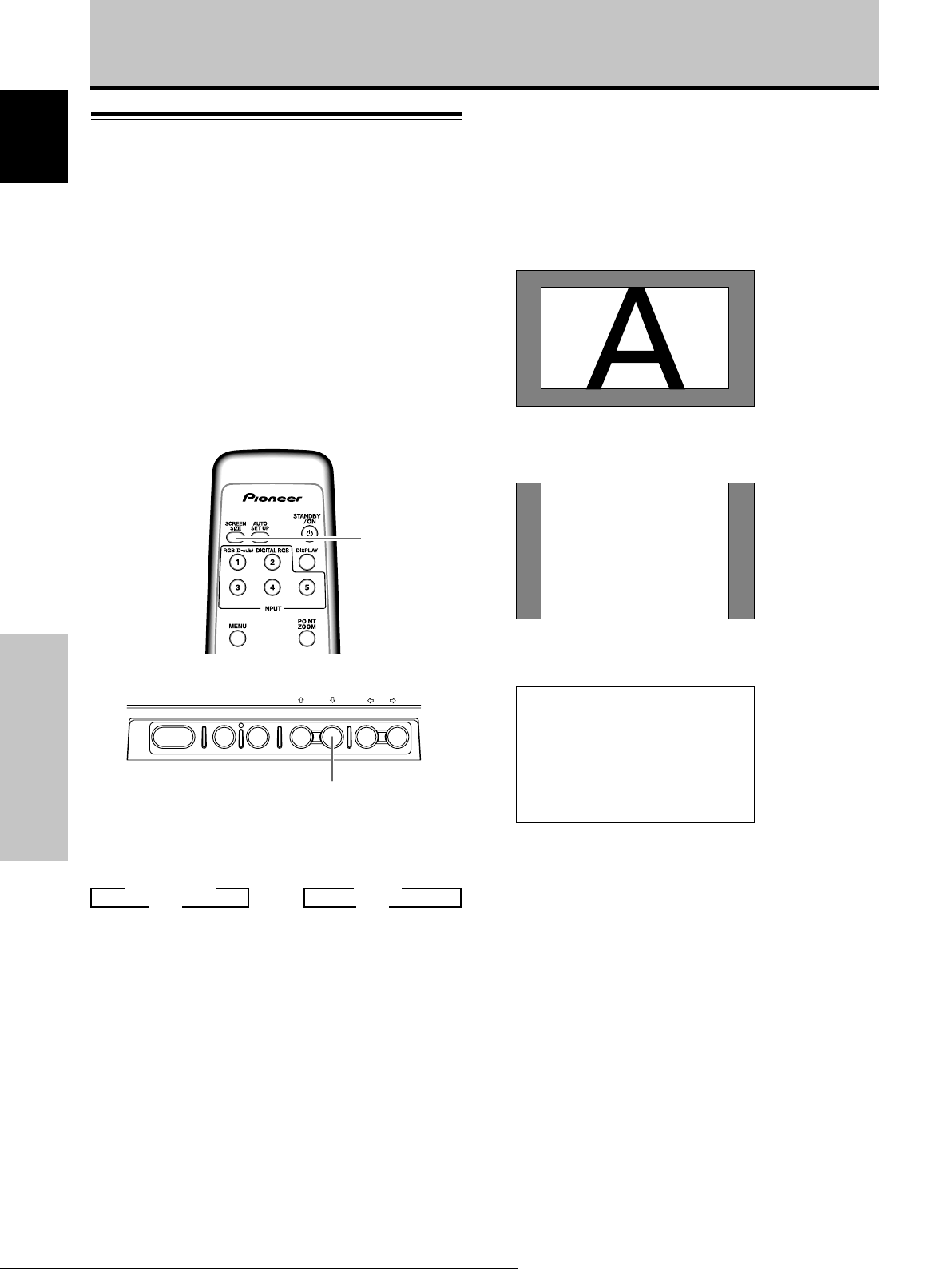
Screen size selection
The size of the image displayed on the screen, and the
range of the image shown can be set in one of four modes.
During personal computer signal input
1 DOT BY DOT
The input signal and the screen maintain a dot to line ratio
of 1:1 and is thus highly faithful to the source.
PDP-427CMX: This unit is designed with horizontally
oblong elements, with the result that the image
displayed will appear more oblong than the original
input signal.
Press the SCREEN SIZE button to select the size.
SCREEN
SIZE
Remote control unit
STANDBY/ON MENU
Operation
The screen size changes each time the SCREEN SIZE
button is pressed as follows.
DISPLAY
/ SET
SCREEN SIZE
Main unit operating panel
– VOL +INPUT SCREEN SIZE
2 4:3
The display fills the screen as much as possible without
altering the aspect ratio of the input signal.
A
3 FULL
The display is presented with a widescreen aspect ratio
of 16:9 and fills the entire screen.
A
3 DOT BY DOT
4:3 2
Consult the Computer signal compatibility table (pages 43
to 48) for information regarding screen sizes supported by
each signal format.
Notes
÷ When the [FULL] setting is used to display a non-wide screen
4:3 picture fully on a wide screen, a portion of the picture may
be cut off or appear deformed.
÷ Be aware that when the display is used for commercial or
public viewing purposes, selecting the [FULL] mode setting
may violate the rights of authors protected under copyright
law.
÷ When [DOT BY DOT] or [4:3] screen size is selected, the
display position is moved slightly each time the power is
turned on, in order to prevent image burning.
or
3 FULL
4:3 2
22
En
Page 29

Enlarging one part of the screen
50
(POINT ZOOM)
This Plasma Display allows enlarging of the screen image.
When enlarging the screen, the 5/∞/2/3 buttons can be
used to move the enlarged viewing area around the
screen.
÷ The range of zoom possible can be confirmed by viewing
the Zoom-Area subscreen at the upper right of the main
screen (A “+” mark will be displayed in the center). The
Zoom-Area subscreen is displayed for about three
seconds whenever the POINT ZOOM button, one of the
5/∞/2/3 buttons, or DISPLAY button is pressed.
Operation
Each time the POINT ZOOM button is pressed, the
zoom ratio alternates in the following order:
3 LEVEL1 3 LEVEL2
LEVEL4 2 LEVEL3 2
÷ LEVEL1 .......... x1
÷ LEVEL2 .......... x1.5
÷ LEVEL3 .......... x2
÷ LEVEL4 .......... x3
2 Using the 5/∞/2/3 buttons, move the screen to
the desired part of the image.
English
DISPLAY
MENU
POINT
ZOOM
5/∞/2/3
SET
1 Press the remote control unit’s POINT ZOOM
button.
66.0
24
R12
24
10
84.3
R12
22.1
Notes
¶ During use of the POINT ZOOM function, the screen size
cannot be changed.
¶ When using the Plasma Display in a profit-making activity, or
when exhibiting images publicly, using the screen size function
to compress or stretch the image may result in infringement of
the copyrights of the image owners.
¶ Pressing the POINT ZOOM and 5/∞/2/3 buttons again will
change the zoom ratio and the position of screen enlarged.
¶ If the input signal changes, or if the menu screen is displayed
and the input is changed, or if the multiscreen mode is
selected, the POINT ZOOM function will be canceled.
10
Operation
10
22.1
Zoom-Area subscreen
23
En
Page 30
Operation
Multiscreen display
English
The Plasma Display’s multiscreen function allows the
simultaneous display of two inputs. The multiscreen
display include two modes, side-by-side and picture-inpicture.
SPLIT
SUB INPUT
1 Press the remote control unit’s SPLIT button.
Each time the button is pressed the multiscreen
display changes in the following order:
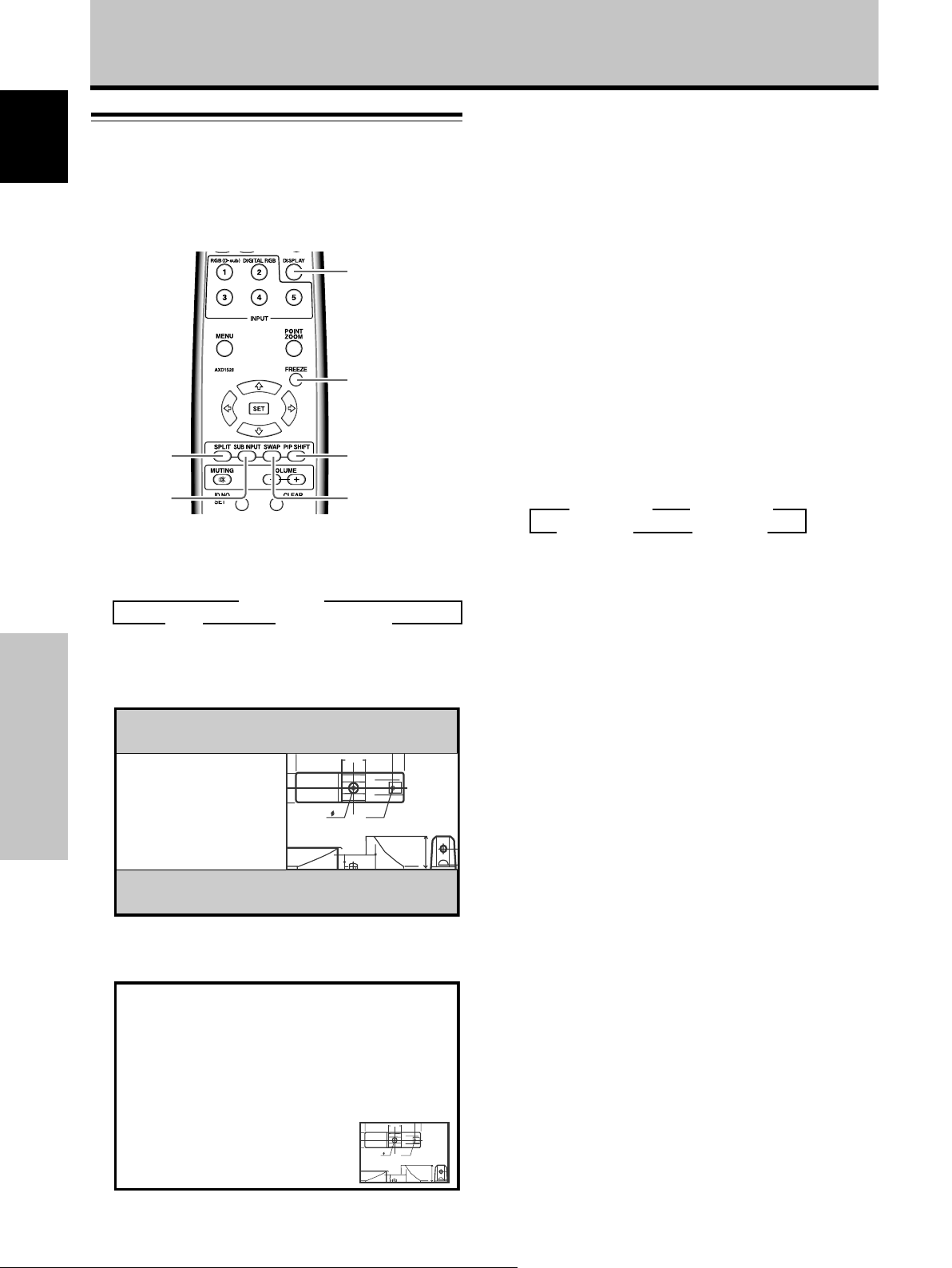
3 Side-by-side
Picture-in-picture 2OFF 2
1 Side-by-side
The main screen is displayed on the left and the
subscreen on the right.
Operation
66.0
24
10
DISPLAY
FREEZE
PIP SHIFT
SWAP
R12
22.1
2 Press the remote control unit’s SUB INPUT button
to select the subscreen input source.
To exchange the main screen and subscreen
inputs:
Press the remote control unit’s SWAP button.
÷ When the side-by-side mode has been selected:
The right and left sides of the display will switch; what
was previously the main screen will now show the
subscreen, and vice versa.
÷ When the picture-in-picture mode has been selected:
What was previously the main screen image will now
appear in reduced size as the subscreen image, and
vice versa.
To change the position of the subscreen in
picture-in-picture mode:
Press the remote control unit’s PIP SHIFT button.
Each time the button is pressed, the position of the
subscreen moves in the following order:
3 Lower right 3 Upper right
Lower left 2 Upper left 2
To display the currently selected input:
Press the DISPLAY button.
If the DISPLAY button is pressed while in multiscreen
mode, the main screen and sub-screen will each be
displayed with its currently selected input.
Notes
¶ When using the Plasma Display in a profit-making activity, or
when exhibiting images publicly, using the screen size function
to compress or stretch the image may result in infringement of
the copyrights of the image owners.
¶ If the multiscreen display is left on for an extended period of
time, or if the same multiscreen display is repeatedly shown
for short periods on an everyday basis, a residual image
pattern may be burned onto the screen.
¶ When selecting the side-by-side mode, the screen image may
appear somewhat rougher, depending on the source used.
¶ The multiscreen mode will be canceled if a menu is opened, or
if POINT ZOOM is performed.
¶ The screen size cannot be changed during multiscreen display.
¶ The sound of the input selected in the main screen is
outputted when using the multiscreen function.
2 Picture-in-picture
The subscreen is displayed in one of the four corners
of the main screen.
66.0
24
10
24
En
R12
22.1
Page 31

Automatic power-off
(POWER MANAGEMENT)
This display is equipped with [POWER MGT.] function,
which allows the unit to automatically switch to standby
mode when no sync signal is detected.
(A warning message is displayed before this function
operates.)
Note
Always turn off the Plasma Display’s main power switch when
not using the display for extended periods of time.
INPUT
MENU
2/3
SET
Remote control unit
STANDBY/ON MENU
DISPLAY
/ SET
Main unit operating panel
1 Press the MENU button to display the menu
screen.
MENU INPUT1
PICTURE
CONTRAST
BRIGHTNESS
H.ENHANCE
V.ENHANCE
SCREEN SETUP OPTION
– VOL +INPUT SCREEN SIZE
2/3INPUTMENU SET
:
0
:
0
:
0
:
0
Operation
2 Use the 2/3 buttons to select [SETUP].
MENU INPUT1
PICTURE
POWER MGT. :OFF
SIGNAL FORMAT
SET
SCREEN SETUP OPTION
CHANGE
MENU
EXIT
3 Press the SET button to confirm selection of
[POWER MGT.].
The factory default setting is [OFF].
Each time the button is pressed, the setting alternates
as follows:
3 OFF
ON 2
÷ OFF ..... The display will continue in operating mode,
regardless of the presence/absence of an
input sync signal.
÷ ON ....... If a sync signal is not detected, a warning
message is first displayed for 8 seconds,
after which the display automatically enters
the standby mode, and the STANDBY/ON
indicator flashes green. If a sync signal is
input again later, the Plasma Display
automatically returns to normal operating
mode (*1).
*1. Except when input signal is G ON SYNC or
composite SYNC
4 When the setup is finished, press the MENU
button to exit the menu screen.
Note
The [POWER MGT.] function must be set individually for each
input (INPUT1 or INPUT2).
To return to operating mode:
To return to normal operation from the [POWER MGT.]
function’s standby mode, either operate your computer,
or press the INPUT button.
English
Operation
PICTURE RESET
SET
ENTER
MENU
EXIT
25
En
Page 32

PICTURE/SCREEN Adjustment
PICTURE adjustment
English
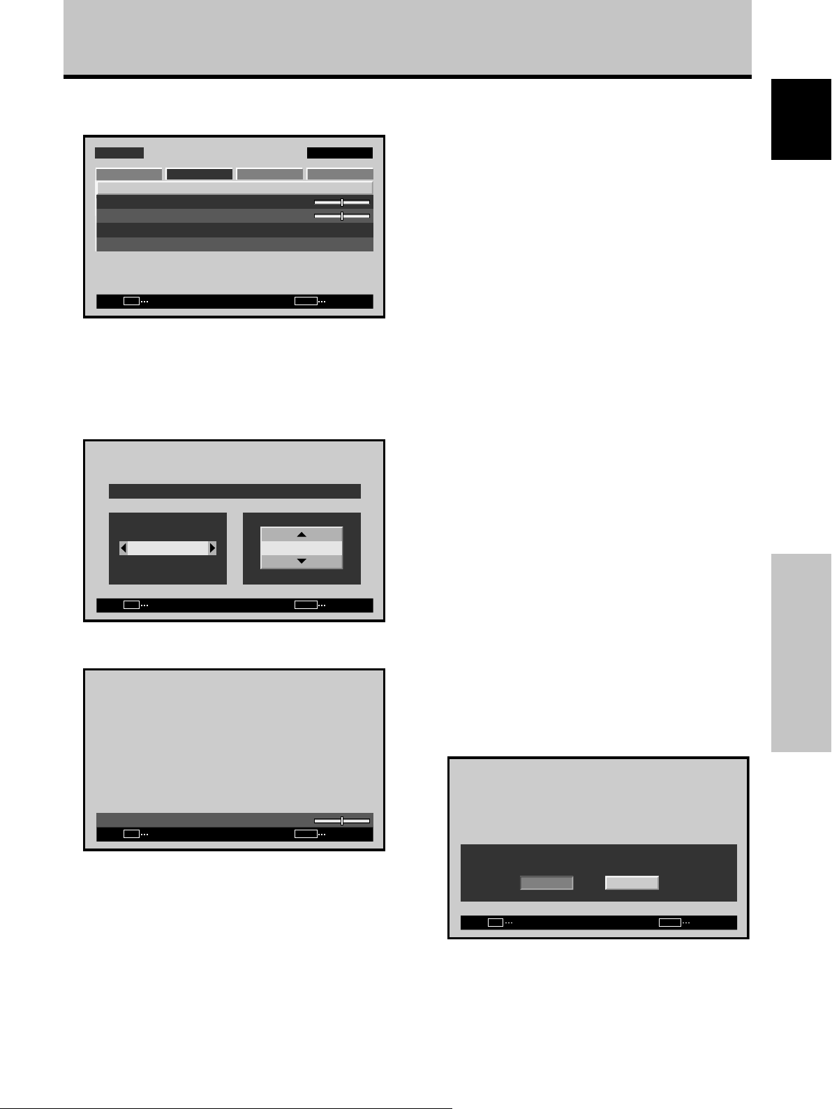
3 Use the 2/3 buttons to adjust the picture quality
as desired.
Remote control unit
STANDBY/ON MENU
DISPLAY
/ SET
Main unit operating panel
1 Press the MENU button to display the menu
screen.
MENU INPUT1
PICTURE
CONTRAST
BRIGHTNESS
H.ENHANCE
V.ENHANCE
PICTURE/SCREEN Adjustment
PICTURE RESET
SET
SCREEN SETUP OPTION
:
:
:
:
ENTER
2 Use the 5/∞ buttons to select the adjustment
item, then press the SET button.
MENU
2/3
SET
5/∞
– VOL +INPUT SCREEN SIZE
2/3MENU SET 5/∞
0
0
0
0
MENU
EXIT
BRIGHTNESS
SET
SET
:
0
MENU
EXIT
4 Press the SET button.
Pressing the SET button writes the value into the
memory and returns the display to the step 2 screen.
5 When the setup is finished, press the MENU
button to exit the menu screen.
Note
Make these adjustments for each input (INPUT1 or INPUT2) and
signals.
[PICTURE] mode adjustment items
Below are brief descriptions of the options that can be set
in the [PICTURE] mode.
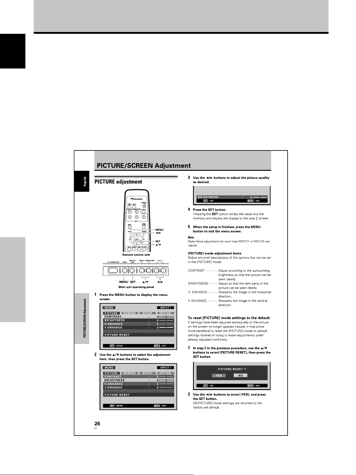
CONTRAST ············· Adjust according to the surrounding
brightness so that the picture can be
seen clearly.
BRIGHTNESS ·········· Adjust so that the dark parts of the
picture can be seen clearly.
H. ENHANCE··········· Sharpens the image in the horizontal
direction.
V. ENHANCE ··········· Sharpens the image in the vertical
direction.
To reset [PICTURE] mode settings to the default
If settings have been adjusted excessively or the picture
on the screen no longer appears natural, it may prove
more beneficial to reset the [PICTURE] mode to default
settings instead of trying to make adjustments under
already adjusted conditions.
1 In step 2 in the previous procedure, use the 5/∞
buttons to select [PICTURE RESET], then press the
SET button.
MENU INPUT1
PICTURE
CONTRAST
BRIGHTNESS
H.ENHANCE
V.ENHANCE
PICTURE RESET
SET
SCREEN SETUP OPTION
ENTER
26
En
PICTURE RESET ?
:
0
:
0
:
0
:
0
SET
YES NO
SET
MENU
EXIT
2 Use the 2/3 buttons to select [YES], and press
the SET button.
MENU
EXIT
All [PICTURE] mode settings are returned to the
factory set default.
Page 33

Adjusting screen POSITION, CLOCK,
and PHASE
By pressing the remote control unit’s AUTO SET UP
button or by selecting [AUTO SETUP MODE] from the
menu, the unit will automatically set the screen position
and clock to best match the current image input.
Note
This setting is supported only when INPUT1 is selected. The
function is disabled when INPUT2 is selected.
When the button is pressed, the optimum
settings are automatically selected for the
current input source.
<automatic adjust>
AUTO
SET UP
PICTURE/SCREEN Adjustment
When the automatic setup mode is
selected, the unit will automatically be
adjusted to the optimum image settings
whenever the power is turned on, the input
source is changed, or the type of input
signal is changed.
MENU
2/3
SET
5/∞
Remote control unit
STANDBY/ON MENU
DISPLAY
/ SET
– VOL +INPUT SCREEN SIZE
English
Press the remote control unit’s AUTO SET UP button.
AUTO SET UP
Note
Optimum settings may not be possible for low-luminance and
certain other signals. In such cases, set the [AUTO SETUP
MODE] to [INACTIVE], and use the manual adjustment methods
explained in the following section, “Adjusting screen
POSITION, CLOCK, and PHASE <manual adjust>“.
2/3MENU SET 5/∞
Main unit operating panel
1 Press the MENU button to display the menu
screen.
MENU INPUT1
PICTURE
CONTRAST
BRIGHTNESS
H.ENHANCE
V.ENHANCE
PICTURE RESET
SET
SCREEN SETUP OPTION
ENTER
:
:
:
:
MENU
0
0
0
0
EXIT
2 Use the 2/3 buttons to select [OPTION].
MENU INPUT1
PICTURE
LANGUAGE
ENERGY SAVE
TIMER SETTING
SCREEN MGT.
AUTO SETUP MODE
AUTO FUNCTION
PIP DETECT
SPLIT FREEZE
SET
SCREEN SETUP OPTION
ENTER
:ENGLISH
:STANDARD
:INACTIVE
:OFF
:ACTIVE
:OFF
MENU
EXIT
PICTURE/SCREEN Adjustment
27
En
Page 34

PICTURE/SCREEN Adjustment
3 Use the 5/∞ buttons to select [AUTO SETUP
English
MODE].
MENU INPUT1
PICTURE
LANGUAGE
ENERGY SAVE
TIMER SETTING
SCREEN MGT.
AUTO SETUP MODE
AUTO FUNCTION
PIP DETECT
SPLIT FREEZE
SET
SCREEN SETUP OPTION
:ENGLISH
:STANDARD
:INACTIVE
:OFF
:ACTIVE
:OFF
CHANGE
MENU
EXIT
Adjusting screen POSITION, CLOCK,
and PHASE
<manual adjust>
4 Press the SET button to activate the setting.
The factory default setting is [INACTIVE].
Each time the button is pressed, the setting alternates
as follows:
3 INACTIVE
ACTIVE 2
5 When finished with the setting, press the MENU
button to return to the normal screen image.
Note
Optimum settings may not be possible for low-luminance and
certain other signals. In such cases, set the [AUTO SETUP
MODE] to [INACTIVE], and use the manual adjustment methods
explained in the following section, “Adjusting screen
POSITION, CLOCK, and PHASE <manual adjust>“.
PICTURE/SCREEN Adjustment
MENU
2/3
SET
5/∞
Remote control unit
STANDBY/ON MENU
DISPLAY
/ SET
– VOL +INPUT SCREEN SIZE
2/3MENU SET 5/∞
Main unit operating panel
1 Press the MENU button to display the menu
screen.
MENU INPUT1
PICTURE
CONTRAST
BRIGHTNESS
H.ENHANCE
V.ENHANCE
PICTURE RESET
SCREEN SETUP OPTION
:
0
:
0
:
0
:
0
28
En
SET
ENTER
MENU
2 Use the 2/3 buttons to select [SCREEN].
MENU INPUT1
PICTURE
POSITION
CLOCK
PHASE
SCREEN RESET
SET
SCREEN SETUP OPTION
ENTER
:
0/ 0
:
:
MENU
0
0
EXIT
EXIT
Page 35
PICTURE/SCREEN Adjustment
3 Use the 5/∞ buttons to select the adjustment
item, then press the SET button.
MENU INPUT1
PICTURE
POSITION
CLOCK
PHASE
SCREEN RESET
SET
SCREEN SETUP OPTION
ENTER
:
0/ 0
:
:
MENU
0
0
EXIT
4 Use the 2/3 and 5/∞ buttons to select the
desired value.
÷ When the [POSITION] item is selected, the 2/3
buttons control movement in the Horizontal
direction (H), and the 5/∞ buttons control
movement in the Vertical direction (V).
POSITION
HV
+88+88
SET
SET
÷ Use the 2/3 buttons for the adjustments of
[CLOCK] and [PHASE].
MENU
EXIT
[SCREEN] mode adjustment items
Below are brief descriptions of the options that can be set
in the [SCREEN] mode.
POSITION
H ················ Adjust the picture’s position to the left or
right.
V ················· Adjust the picture’s position upward or
downward.
CLOCK ········· Adjust letter breakup or noise on the
screen. This setting adjusts the unit’s
internal clock signal frequency that
corresponds to the input video signal.
PHASE·········· Adjust so that there is minimum flicker of
screen letters or color misalignment. This
setting adjusts the phase of the internal
clock signal adjusted by the [CLOCK]
setting.
Notes
÷ The [CLOCK] and [PHASE] adjustment items are supported
only for INPUT1.
÷ When the [CLOCK] frequency is changed, the [POSITION]
command’s horizontal [H] option may require readjustment.
÷ If the adjustment items in the [SCREEN] mode are adjusted
excessively, the picture may not be displayed properly.
÷ When the [AUTO SETUP MODE] set to [ACTIVE], selecting the
[POSITION] and [CLOCK] adjust modes will cause a message
to be displayed on the screen, but adjustment is possible.
However, if the input source is changed, the adjustment value
stored in memory will be the one automatically set with the
auto setup mode. If you wish to record a manually set
adjustment value, set the [AUTO SETUP MODE] to [INACTIVE]
(pages 27 to 28) before beginning your adjustments.
To reset [SCREEN] mode settings to the default
If settings have been adjusted excessively or the picture
on the screen no longer appears natural, it may prove
more beneficial to reset the [SCREEN] mode to default
settings instead of trying to make adjustments under
already adjusted conditions.
1 In step 3 in the previous procedure, use the 5/∞
buttons to select [SCREEN RESET], then press the
SET button.
English
PICTURE/SCREEN Adjustment
CLOCK
SET
SET
:
0
MENU
EXIT
Note
If INPUT2 is selected, only the [POSITION] can be adjusted.
5 Press the SET button.
Pressing the SET button writes the value into the
memory and returns the display to the step 3 screen.
6 When adjustment is finished, press the MENU
button to exit the menu screen.
SCREEN RESET ?
YES NO
SET
SET
MENU
EXIT
2 Use the 2/3 buttons to select [YES], and press
the SET button.
All [SCREEN] mode settings are returned to the
factory set default.
29
En
Page 36

Other Operations
Setting the ORBITER
English
This function gradually shifts the screen position at time
intervals.
÷ This function is not supported when using the POINT
ZOOM function.
Remote control unit
STANDBY/ON MENU
DISPLAY
/ SET
SCREEN SIZE
MENU
2/3
5/∞
– VOL +INPUT
2 Use the 2/3 buttons to select [OPTION].
MENU INPUT1
PICTURE
LANGUAGE
ENERGY SAVE
TIMER SETTING
SCREEN MGT.
AUTO SETUP MODE
AUTO FUNCTION
PIP DETECT
SPLIT FREEZE
SET
SCREEN SETUP OPTION
ENTER
:ENGLISH
:STANDARD
:INACTIVE
:OFF
:ACTIVE
:OFF
MENU
EXIT
3 Use the 5/∞ buttons to select [SCREEN MGT.],
then press the SET button.
MENU INPUT1
PICTURE
LANGUAGE
ENERGY SAVE
TIMER SETTING
SCREEN MGT.
AUTO SETUP MODE
AUTO FUNCTION
PIP DETECT
SPLIT FREEZE
SET
SCREEN SETUP OPTION
ENTER
:ENGLISH
:STANDARD
:INACTIVE
:OFF
:ACTIVE
:OFF
MENU
EXIT
Main unit operating panel
1 Press the MENU button to display the menu
screen.
Other Operations
MENU INPUT1
PICTURE
CONTRAST
BRIGHTNESS
H.ENHANCE
V.ENHANCE
PICTURE RESET
SET
SCREEN SETUP OPTION
ENTER
4 Use the 5/∞ buttons to select [ORBITER].
2/3MENU 5/∞
ORBITER
SOFT FOCUS
SCREEN MANAGEMENT
SET
CHANGE
:OFF
:OFF
MENU
EXIT
5 Press the 2/3 buttons to activate the setting.
:
0
:
0
:
0
:
0
MENU
EXIT
The factory default setting is [OFF].
Each time the button is pressed, the setting alternates
as follows:
3 OFF
MODE3 2 MODE2 2
3 MODE1
÷ OFF ............... The [ORBITER] is not being used.
÷ MODE1 ......... The image size is reduced, and the
screen display position is changed.
÷ MODE2 ......... The image size is enhanced, and the
screen display position is changed.
÷ MODE3 ......... Screen position is shifted in
accordance with dot-by-dot
orientation.
30
En
6 When finished with the setting, press the MENU
button to return to the normal screen image.
Note
The [ORBITER] setting affects all input sources.
Page 37

Setting the SOFT FOCUS
Images are softened by suppressing the edge contrast.
MENU
2/3
5/∞
Other Operations
3 Use the 5/∞ buttons to select [SCREEN MGT.],
then press the SET button.
MENU INPUT1
PICTURE
LANGUAGE
ENERGY SAVE
TIMER SETTING
SCREEN MGT.
AUTO SETUP MODE
AUTO FUNCTION
PIP DETECT
SPLIT FREEZE
SET
SCREEN SETUP OPTION
ENTER
:ENGLISH
:STANDARD
:INACTIVE
:OFF
:ACTIVE
:OFF
MENU
EXIT
4 Use the 5/∞ buttons to select [SOFT FOCUS].
English
Remote control unit
STANDBY/ON MENU
DISPLAY
/ SET
SCREEN SIZE
– VOL +INPUT
2/3MENU 5/∞
Main unit operating panel
1 Press the MENU button to display the menu
screen.
MENU INPUT1
PICTURE
CONTRAST
BRIGHTNESS
H.ENHANCE
V.ENHANCE
PICTURE RESET
SET
SCREEN SETUP OPTION
ENTER
:
:
:
:
MENU
0
0
0
0
EXIT
2 Use the 2/3 buttons to select [OPTION].
SCREEN MANAGEMENT
ORBITER
SOFT FOCUS
SET
CHANGE
:OFF
:OFF
MENU
EXIT
5 Press the 2/3 buttons to activate the setting.
The factory default setting is [OFF].
Each time the button is pressed, the setting alternates
as follows:
3 OFF
4 2
3 1
3 2 2 2
÷ OFF ............... The [SOFT FOCUS] setting is
canceled.
÷ 1 to 4 ............. Settings for [SOFT FOCUS].
Softened increases in the order 1, 2,
3, 4.
6 When finished with the setting, press the MENU
button to return to the normal screen image.
Note
The [SOFT FOCUS] setting affects all input sources.
Other Operations
MENU INPUT1
PICTURE
LANGUAGE
ENERGY SAVE
TIMER SETTING
SCREEN MGT.
AUTO SETUP MODE
AUTO FUNCTION
PIP DETECT
SPLIT FREEZE
SET
SCREEN SETUP OPTION
ENTER
:ENGLISH
:STANDARD
:INACTIVE
:OFF
:ACTIVE
:OFF
MENU
EXIT
31
En
Page 38

Other Operations
Energy saving settings
English
(ENERGY SAVE)
The power control function allows screen brightness to
be suppressed as a means of lowering power
consumption and reducing display deterioration.
Remote control unit
STANDBY/ON MENU
1 Press the MENU button to display the menu
screen.
Other Operations
MENU INPUT1
PICTURE
CONTRAST
BRIGHTNESS
H.ENHANCE
V.ENHANCE
PICTURE RESET
SET
ENTER
2 Use the 2/3 buttons to select [OPTION].
MENU INPUT1
PICTURE
LANGUAGE
ENERGY SAVE
TIMER SETTING
SCREEN MGT.
AUTO SETUP MODE
AUTO FUNCTION
PIP DETECT
DISPLAY
/ SET
Main unit operating panel
SCREEN SETUP OPTION
SCREEN SETUP OPTION
:
:
:
:
:ENGLISH
:STANDARD
:INACTIVE
:OFF
:ACTIVE
MENU
2/3
SET
5/∞
– VOL +INPUT SCREEN SIZE
2/3MENU SET 5/∞
0
0
0
0
MENU
EXIT
3 Use the 5/∞ buttons to select [ENERGY SAVE].
MENU INPUT1
PICTURE
LANGUAGE
ENERGY SAVE
TIMER SETTING
SCREEN MGT.
AUTO SETUP MODE
AUTO FUNCTION
PIP DETECT
SPLIT FREEZE
SET
SCREEN SETUP OPTION
CHANGE
:ENGLISH
:STANDARD
:INACTIVE
:OFF
:ACTIVE
:OFF
MENU
EXIT
4 Press the SET button to select [ENERGY SAVE]
setting.
The factory default setting is [STANDARD] (PDP607CMX/PDP-427CMX)/[STANDARD1] (PDP-507CMX).
Each time the SET button is pressed, the setting
changes as follows:
3
3
STANDARD (STANDARD1
MUTE 2
MODE3 2 MODE2 2
STANDARD2)
3 AUTO
MODE1 2
÷ STANDARD ...... Normal image brightness (PDP-
607CMX/PDP-427CMX)
÷ STANDARD1, STANDARD2 .............
Normal image brightness.
The appearance may be different
depending on the type of image.
(PDP-507CMX)
÷ AUTO ............... Brightness is set automatically in
response to ambient lighting
conditions so as to produce
optimum image appearance. (PDP507CMX/PDP-427CMX)
÷ MODE1 ............ Brightness is controlled in
accordance with input signal, but
power consumption is less than that
used in [STANDARD] (STANDARD1,
STANDARD2) mode.
÷ MODE2 ............ Brightness is controlled in
accordance with input signal, but
power consumption is less than that
used in [MODE1].
÷ MODE3 ............ Brightness is set at fixed level,
regardless of input signal level.
Effective at reducing screen aging
due to burned lag images, etc.
÷ MUTE* ............. Use to temporarily turn off the
displayed image.
*To restore the image
÷ Press either of the MENU, DISPLAY, SUB INPUT, SPLIT,
SWAP, or PIP SHIFT buttons.
÷ Switches the input signal.
÷ Sets unit to standby mode.
5 When finished with the setting, press the MENU
button to return to the normal screen image.
Note
The [ENERGY SAVE] setting affects all input sources.
32
En
Page 39

Automatic input switching
(AUTO FUNCTION)
This display is equipped with an optional [AUTO
FUNCTION] selector. When enabled, the selector
automatically switches the display’s input source to INPUT1
when an image signal is detected at the INPUT1 terminal.
Other Operations
2 Use the 2/3 buttons to select [OPTION].
MENU INPUT1
PICTURE
LANGUAGE
ENERGY SAVE
TIMER SETTING
SCREEN MGT.
AUTO SETUP MODE
AUTO FUNCTION
PIP DETECT
SPLIT FREEZE
SET
SCREEN SETUP OPTION
ENTER
:ENGLISH
:STANDARD
:INACTIVE
:OFF
:ACTIVE
:OFF
MENU
English
EXIT
MENU
2/3
SET
5/∞
Remote control unit
STANDBY/ON MENU
DISPLAY
/ SET
– VOL +INPUT SCREEN SIZE
2/3MENU SET 5/∞
Main unit operating panel
1 Press the MENU button to display the menu
screen.
MENU INPUT1
PICTURE
CONTRAST
BRIGHTNESS
H.ENHANCE
V.ENHANCE
PICTURE RESET
SET
SCREEN SETUP OPTION
ENTER
:
:
:
:
MENU
0
0
0
0
EXIT
3 Use
the 5/∞ buttons to select [AUTO FUNCTION].
MENU INPUT1
PICTURE
LANGUAGE
ENERGY SAVE
TIMER SETTING
SCREEN MGT.
AUTO SETUP MODE
AUTO FUNCTION
PIP DETECT
SPLIT FREEZE
SET
SCREEN SETUP OPTION
CHANGE
:ENGLISH
:STANDARD
:INACTIVE
:OFF
:ACTIVE
:OFF
MENU
EXIT
4 Press the SET button to select [INPUT1].
The factory default setting is [OFF]. Each time the
SET button is pressed, the selector function switches
alternately as shown:
3 OFF
INPUT1 2
÷ OFF .......... [AUTO FUNCTION] is disabled.
÷ INPUT1 ..... ÷ When a signal is detected at INPUT1,
the input source automatically
switches to [INPUT1].
÷ After the [AUTO FUNCTION] mode
has caused the input to switch, if the
input signal is no longer detected, the
input source reverts to the one
selected before operation of the
[AUTO FUNCTION] mode.
÷ If the input changes when the unit is
in [AUTO FUNCTION] mode, pressing
the INPUT button to select a different
input will cause the [AUTO
FUNCTION] mode to be temporarily
disabled, but it can be enabled again
by turning the power ON/OFF.
5 When finished with the setting, press the MENU
button to return to the normal screen image.
Notes
÷ The [AUTO FUNCTION] for [INPUT1] is supported only when a
separate SYNC or composite SYNC analog RGB signal is input.
(When a G ON SYNC or component video signal is input,
[AUTO FUNCTION] is disabled.)
÷ The [AUTO FUNCTION] setting affects all input sources.
33
Other Operations
En
Page 40
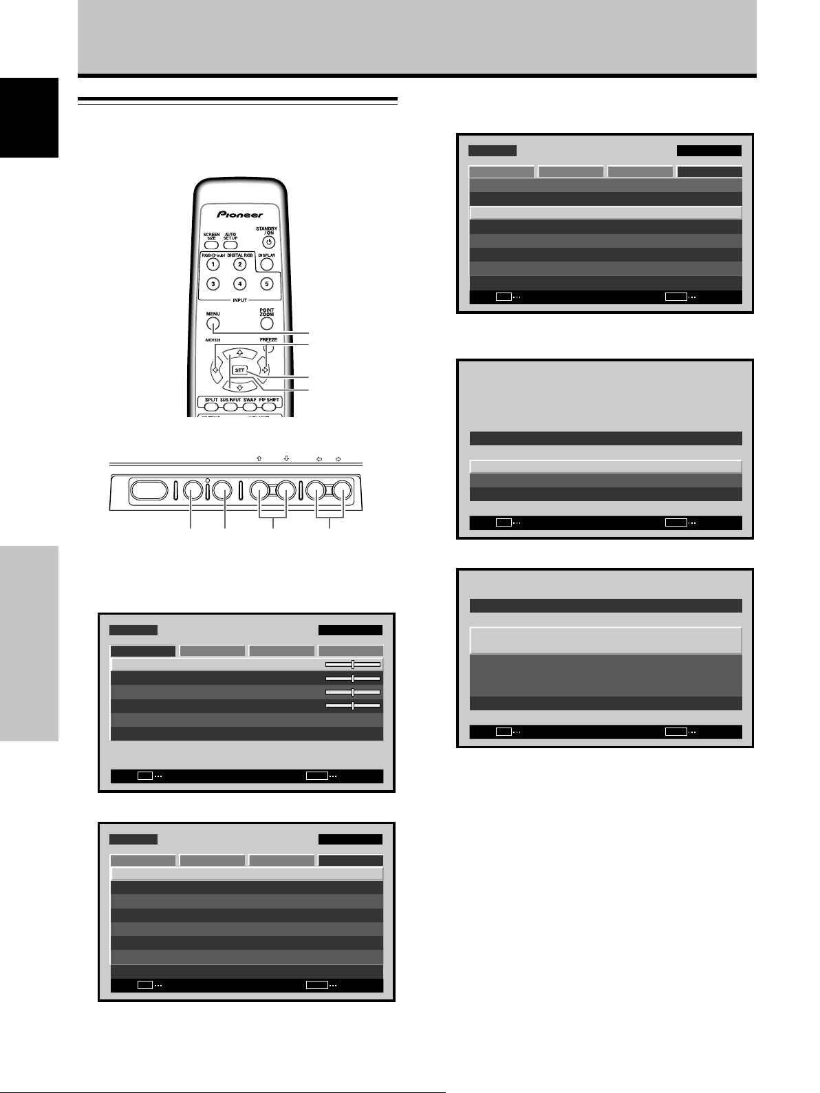
Other Operations
Setting the PRESENT TIME
English
Sets the current time, day of the week and daylight
savings time.
3 Use the 5/∞ buttons to select [TIMER SETTING],
then press the SET button.
MENU INPUT1
PICTURE
LANGUAGE
ENERGY SAVE
TIMER SETTING
SCREEN MGT.
AUTO SETUP MODE
AUTO FUNCTION
PIP DETECT
SPLIT FREEZE
SET
SCREEN SETUP OPTION
ENTER
:ENGLISH
:STANDARD
:INACTIVE
:OFF
:ACTIVE
:OFF
MENU
EXIT
Remote control unit
STANDBY/ON MENU
DISPLAY
/ SET
Main unit operating panel
1 Press the MENU button to display the menu
screen.
MENU INPUT1
PICTURE
CONTRAST
Other Operations
BRIGHTNESS
H.ENHANCE
V.ENHANCE
SCREEN SETUP OPTION
MENU
2/3
SET
5/∞
– VOL +INPUT SCREEN SIZE
4 Use the 5/∞ buttons to select [PRESENT TIME],
then press the SET button.
TIMER SETTING
PRESENT TIME
PROGRAM/REPEAT
RETURN
SET
ENTER
:OFF
MENU
EXIT
2/3MENU SET 5/∞
5 Use the 2/3/5/∞ buttons to set each menu item.
PRESENT TIME
DAYLIGHT
SAVING TIME
:
0
:
0
:
0
:
0
SET
RETURN
MONDAY
12:00:00
:OFF
PICTURE RESET
SET
ENTER
MENU
2 Use the 2/3 buttons to select [OPTION].
MENU INPUT1
PICTURE
LANGUAGE
ENERGY SAVE
TIMER SETTING
SCREEN MGT.
AUTO SETUP MODE
AUTO FUNCTION
PIP DETECT
SPLIT FREEZE
SET
SCREEN SETUP OPTION
ENTER
:ENGLISH
:STANDARD
:INACTIVE
:OFF
:ACTIVE
:OFF
MENU
34
En
EXIT
EXIT
SET
CHANGE
MENU
EXIT
÷ DAYLIGHT SAVING TIME
.................................. Use to set to daylight savings
time.
ON: Displays time as present time + 1 hour.
OFF: Disables [DAYLIGHT SAVING TIME] mode.
÷ Week ......................... Set current day of the week.
÷ Hour, Minute ............. Sets to current time.
6 When finished with the setting, use the 5/∞
buttons to select [RETURN], then press the SET
button to return to the [TIMER SETTING] menu.
Note
The [TIMER SETTING] setting affects all input sources.
Page 41

Activating the timer
The timer can be used to operate a preset program.
Other Operations
3 Use the 5/∞ buttons to select [TIMER SETTING],
then press the SET button.
MENU INPUT1
PICTURE
LANGUAGE
ENERGY SAVE
TIMER SETTING
SCREEN MGT.
AUTO SETUP MODE
AUTO FUNCTION
PIP DETECT
SPLIT FREEZE
SET
SCREEN SETUP OPTION
ENTER
:ENGLISH
:STANDARD
:INACTIVE
:OFF
:ACTIVE
:OFF
MENU
EXIT
English
MENU
2/3
SET
5/∞
Remote control unit
STANDBY/ON MENU
DISPLAY
/ SET
– VOL +INPUT SCREEN SIZE
2/3MENU SET 5/∞
Main unit operating panel
1 Press the MENU button to display the menu
screen.
MENU INPUT1
PICTURE
CONTRAST
BRIGHTNESS
H.ENHANCE
V.ENHANCE
PICTURE RESET
SET
SCREEN SETUP OPTION
ENTER
:
:
:
:
MENU
0
0
0
0
EXIT
2 Use the 2/3 buttons to select [OPTION].
MENU INPUT1
PICTURE
LANGUAGE
ENERGY SAVE
TIMER SETTING
SCREEN MGT.
AUTO SETUP MODE
AUTO FUNCTION
PIP DETECT
SPLIT FREEZE
SET
SCREEN SETUP OPTION
ENTER
:ENGLISH
:STANDARD
:INACTIVE
:OFF
:ACTIVE
:OFF
MENU
EXIT
4 Use the 5/∞ buttons to select [PROGRAM/
REPEAT].
TIMER SETTING
PRESENT TIME
PROGRAM/REPEAT
RETURN
SET
CHANGE
:OFF
MENU
EXIT
5 Press the 2/3 buttons to activate the setting.
The factory default setting is [OFF].
Each time the button is pressed, the setting alternates
as follows:
3 OFF
REPEAT 2 PROGRAM 2
6 When finished with the setting, use the 5/∞
buttons to select [RETURN], then press the SET
button to return to the normal screen image.
[PROGRAM] setting
÷ Every day, power turns on at 10:00.
Input and function settings are the same as those set
the last time the unit was turned OFF.
÷ At 20:00 (8 o'clock PM), the screen turns white.
At 21:00 (9 o'clock PM), power turns OFF.
[REPEAT] setting
÷ Screens for INPUT1 and INPUT2 are displayed
alternately for ten minutes duration each.
Other Operations
35
En
Page 42

Other Operations
Setting the subscreen mode
English
(PIP DETECT)
During picture-in-picture display, if no subscreen input
signal is detected, the black borders of the subscreen are
automatically turned off.
The subscreen mode function is disabled during side-byside display.
÷ The lack of a subscreen input signal means there is no
video signal or sync signal.
MENU
2/3
SET
5/∞
Remote control unit
STANDBY/ON MENU
DISPLAY
/ SET
2 Use the 2/3 buttons to select [OPTION].
MENU INPUT1
PICTURE
LANGUAGE
ENERGY SAVE
TIMER SETTING
SCREEN MGT.
AUTO SETUP MODE
AUTO FUNCTION
PIP DETECT
SPLIT FREEZE
SET
SCREEN SETUP OPTION
ENTER
:ENGLISH
:STANDARD
:INACTIVE
:OFF
:ACTIVE
:OFF
MENU
EXIT
3 Use the 5/∞ buttons to select [PIP DETECT].
MENU INPUT1
PICTURE
LANGUAGE
ENERGY SAVE
TIMER SETTING
SCREEN MGT.
AUTO SETUP MODE
AUTO FUNCTION
PIP DETECT
SPLIT FREEZE
SET
SCREEN SETUP OPTION
CHANGE
:ENGLISH
:STANDARD
:INACTIVE
:OFF
:ACTIVE
:OFF
MENU
EXIT
4 Press the SET button to activate the setting.
The factory default setting is [ACTIVE].
Each time the button is pressed, the setting alternates
– VOL +INPUT SCREEN SIZE
as follows:
3 ACTIVE
Other Operations
Main unit operating panel
1 Press the MENU button to display the menu
screen.
MENU INPUT1
PICTURE
CONTRAST
BRIGHTNESS
H.ENHANCE
V.ENHANCE
PICTURE RESET
SET
SCREEN SETUP OPTION
ENTER
INACTIVE 2
÷ ACTIVE ........... When no subscreen input signal is
2/3MENU SET 5/∞
detected during multiscreen display,
the black border of the subscreen
will disappear after 3 seconds.
÷ INACTIVE ....... Subscreens with no input will be left
with the black border visible.
5 When finished with the setting, press the MENU
button to return to the normal screen image.
:
0
:
0
:
0
:
0
MENU
EXIT
Note
The [PIP DETECT] setting affects all input sources.
36
En
Page 43

Setting the memo screen
(SPLIT FREEZE)
When set to any setting other than [OFF], the image
displayed when the FREEZE button is pressed will be
displayed in a subscreen as a freeze-frame image.
MENU
2/3
FREEZE
SET
5/∞
Remote control unit
STANDBY/ON MENU
DISPLAY
/ SET
Main unit operating panel
1 Press the MENU button to display the menu
screen.
MENU INPUT1
PICTURE
CONTRAST
BRIGHTNESS
H.ENHANCE
V.ENHANCE
PICTURE RESET
SET
SCREEN SETUP OPTION
ENTER
– VOL +INPUT SCREEN SIZE
2/3MENU SET 5/∞
:
0
:
0
:
0
:
0
MENU
EXIT
Other Operations
2 Use the 2/3 buttons to select [OPTION].
MENU INPUT1
PICTURE
LANGUAGE
ENERGY SAVE
TIMER SETTING
SCREEN MGT.
AUTO SETUP MODE
AUTO FUNCTION
PIP DETECT
SPLIT FREEZE
SET
SCREEN SETUP OPTION
ENTER
:ENGLISH
:STANDARD
:INACTIVE
:OFF
:ACTIVE
:OFF
MENU
EXIT
3 Use the 5/∞ buttons to select [SPLIT FREEZE].
MENU INPUT1
PICTURE
LANGUAGE
ENERGY SAVE
TIMER SETTING
SCREEN MGT.
AUTO SETUP MODE
AUTO FUNCTION
PIP DETECT
SPLIT FREEZE
SET
SCREEN SETUP OPTION
CHANGE
:ENGLISH
:STANDARD
:INACTIVE
:OFF
:ACTIVE
:OFF
MENU
EXIT
4 Press the SET button to activate the setting.
The factory default setting is [OFF].
Each time the button is pressed, the setting alternates
as follows:
3 OFF 3 S BY S 3 PIP
÷ OFF ................ The still picture displayed at the time
the FREEZE button was pressed is
displayed as a single fullscreen
image.
÷ S BY S ............ When the FREEZE button is
pressed, the freeze-frame image will
be displayed in the side-by-side
subscreen.
÷ PIP .................. When the FREEZE button is
pressed, the freeze-frame image will
be displayed in the picture-in-picture
(left-bottom to left-top) subscreen.
5 When finished with the setting, press the MENU
button to return to the normal screen image.
English
Other Operations
Notes
This function is subject to the following conditions:
÷ It does not function during multi-screen display.
÷ It will be disabled if the FREEZE button is pressed again while
the function is operating.
÷ It will be disabled if set to multi-screen display while the
function is operating.
÷ The [SPLIT FREEZE] seting afects all input sources.
37
En
Page 44

Additional Information
Cleaning
English
Regular cleaning will extend the life and performance of
this unit. The recommended way to clean the display and
related parts is described below.
Before cleaning, be sure to unplug the power cord from
the power outlet.
Cleaning the display panel body and remote
control
Do not under any circumstances use solvents such as
benzine or thinner for cleaner. Use of such liquids may
cause deterioration or peeling of paint from the display or
remote control unit.
Wipe the display and remote control gently with a soft
cloth. In the case of excessive dirt buildup, dampen a soft
cloth with a diluted neutral cleaning detergent and after
wringing the cloth thoroughly, wipe the component and
then dry it with a dry soft cloth.
Cleaning the vents
As a general rule, use a vacuum cleaner about once a
month to clean the vents on the rear panel of the display
of dust buildup (set the vacuum cleaner to its weakest
setting when doing this).
Using the unit without cleaning it of dust will cause the
internal temperature to increase, resulting in possible
breakdown or fire.
PDP-607CMX
Vents
Vents
Cleaning the screen
After dusting, wipe the screen gently using the supplied
cleaning cloth or another soft cloth (cotton, flannel, etc.).
Do not use tissue or a rough cloth. As the surface of the
screen is easily scratched, do not rub it or hit it with a
hard object.
If you clean the surface of the screen with a wet cloth,
water droplets on the surface may enter into the product,
resulting in malfunction.
Additional Information
PDP-507CMX
Vents
PDP-427CMX
Vents
Vents Vents
Vents
Vents Vents
Vents
38
En
Vents Vents
Page 45

Additional Information
Troubleshooting
What may at first seem to be an malfunction, may be
remedied with a quick check.
Please check to see if a warning is displayed on the
screen. If displayed, refer to the table below and check
the mode. If there is no display check to see if the
problem is listed on page 40. The problem may also be
caused by something other than this unit so please also
check the other components being used such as a video
deck. If the problem can still not be solved please consult
the dealer where this unit was purchased.
About the self diagnosis mode
Messages appear on the bottom of this unit’s screen to
indicate operation or connection faults. After message
confirmation, check the condition of the unit.
ERROR MESSAGE
CAUTION
OUT OF RANGE
or
CAUTION
UNSUPPORTED SIGNAL
or
SIGNAL NG
WARNING
THERMAL ALERT
SHUT DOWN
WARNING
FAN FAILURE
SHUT DOWN
¶ The current input signal is
¶ Tu rn off main power (pages
¶ Is ambient temperature
¶ Remove any objects
¶ Cooling fan has
REMEDY
not supported by the unit.
Check the Computer signal
compatibility table on
pages 43 to 48, and change
the computer’s output
signal setting appropriately.
9 to 11).
above 40 °C?
blocking the cooling vents
on the Plasma Display.
malfunctioned.
Immediately turn off
power, remove power plug
from its outlet, and consult
a Pioneer service center or
your dealer.
English
ERROR
INVALID KEY ENTRY
SHUT DOWN
¶ An invalid operation has
been attempted. Check
input signals, connections
and other settings.
¶ Tu rn off main power, wait
for 1 to 2 minutes, then try
turning power on again. If
problem persists, remove
power plug from its outlet
and consult a Pioneer
service center or your
dealer.
Additional Information
39
En
Page 46
Additional Information
General problems
English
• No power.
• Unit cannot be operated.
• Remote control does not
operate.
• Picture is cut off.
• Strange color, light color, or
dark, or color misalignment.
• Power is suddenly turned
off.
• No picture.
Problem Possible Solution
• Is the power cord disconnected? (page 16)
• Has the MAIN POWER switch been switched on? (pages 9 to 11)
• External influences such as lightning, static electricity, etc., may cause improper operation. In this
case, operate the unit after first turning the MAIN POWER off/on, or unplugging the power cord
and re-plugging it in after 1 to 2 minutes.
• Are batteries inserted with polarity (+, –) correctly aligned? (page 8)
• Are batteries worn out? (Replace with new batteries.)
• Is any object occluding the remote signal receiver? (page 8)
• Point the remote control unit toward the remote signal receiver when operating (page 8).
• Is the selected screen size correct?
Switch to another screen size (page 22).
• Are [SCREEN] mode adjustments such as picture size made correctly? (pages 22 to 23 and 28 to 29)
• Is the POINT ZOOM function being used? (page 23)
• Adjust the picture tone (page 26).
• Is the room too bright?
The picture may look dark in a room that is too bright.
• The unit’s internal temperature has increased. (Air vents are blocked.)
Remove any objects blocking vent or clean (page 38).
• Is the [POWER MGT.] function set to [ON]? (page 25)
• Is connection to other components correct? (pages 14 to 15)
• Has setup been done correctly after connection? (pages 18 to 19)
• Is the correct input selected? (page 20)
• Is a non-compatible signal being input? (pages 43 to 48)
• Is the [PICTURE] setting correct? (page 26)
Problems commonly mistaken as breakdown
Problem Possible Solution
• The screen is displayed in a
small size.
• Letter breakup on screen.
Additional Information
•A sharp sound is sometimes
heard from the cabinet.
• Bright portions of image
appear to be losing intensity.
• Speckles or noise appears on
screen.
• Stripes appear on the screen.
• Sound is heard from inside
the unit.
• Fan speed changes.
• ON (green) indicator doesn’t
light.
• Is the correct screen size selected? (pages 22 to 23 and 28 to 29)
• Adjust using [SCREEN] mode on the menu screen (pages 28 to 29).
If there is still no improvement, this unit may be limiting the displayable range. Check the
Computer signal compatibility table (pages 43 to 48).
• Expansion/contraction caused by surrounding temperature change may result in sound being
heard from the cabinet. This is not a malfunction.
• When the video input signal’s level is too high, the bright portions may appear to be losing their
intensity.
Increase the adjustment level of the contrast and check the picture (page 26).
• May be caused by radio wave interference from appliances with motors such as hair dryers,
electric vacuum cleaners, electric power drills, ignition systems of cars, motorcycles etc., switch
devises such as thermostats etc., neon signs or electrical discharge from power lines etc.
• May be caused by radio wave mingling from TV station, FM station, amateur radios, public radios
(simplified radios) etc., or a nearby personal computer, TV, or video/audio component.
•A strong electromagnetic field may cause picture distortion and similar problems.
• Normal sound of the cooling fan and internal sliding parts of the Plasma Display panel. Not a
malfunction.
• Fan speed changes automatically in accordance with ambient conditions. Not a malfunction.
• The ON indicator may not light in some cases, depending on the settings performed by the
installer. Consult with your installation technician.
40
En
Page 47

Precautions regarding use
Panel sticking and after-image lag
• Displaying the same images such as still images for a long
time may cause after-image lagging.
This may occur in the following two cases.
1. After-image lagging due to remaining electrical load
When image patterns with very high peak luminance are
displayed for more than 1 minute, after-image lagging may
occur due to the remaining electric load. The after-images
remaining on the screen will disappear when moving images
are displayed. The time for the after-images to disappear
depends on the luminance of the still images and the time
they had been displayed.
2. After-image (lag image) due to burning
Avoid displaying the same image on the Plasma Display
continuously over a long period of time. If the same image is
displayed continuously for several hours, or for shorter periods
of time over several days, a permanent after-image may
remain on the screen due to burning of the fluorescent
materials. Such images may become less noticeable if moving
images are later displayed, but they will not disappear
completely.
The same kind of burning of a lag image may also be produced
after extended multi-hour use, or recurrent daily use for shorter
periods of a single [4:3] screen size, or [DOT BY DOT] image.
Except in cases where violation of intellectual property rights
may be involved (pages 22 and 23), it is recommended that lagimage burning be avoided by selecting a screen size that
displays images over the entire screen (page 22).
• In addition, the [ORBITER] function (page 30) and [ENERGY
SAVE] function (page 32) can also be used to reduce the
chance of lag image formation.
Note
Special precautions must be employed when using the
Plasma Display as a surveillance monitor or in other
applications where a fixed image will be displayed for
extended periods of time. Before using the monitor in such
applications, consult your dealer for advice.
When using this unit as a monitor for a surveillance
camera, it is recommended to set the [ENERGY SAVE]
function to [MODE3] or [MODE2].
About the Plasma Display’s protection function
The brightness of this display will deteriorate slightly when an
image with little movement such as a photograph or computer
image is continuously displayed. This is caused by the Plasma
Display’s protection function which detects images with slight
movement and automatically adjusts brightness to protect the
display, and is not a malfunction.
The screen-saver function begins operating when the display
detects no or little screen movement for a period of about three
minutes; the function is an automatic feature and cannot be
turned OFF.
Pixel failure
The Plasma Display screen is composed of a high numbers of
tiny pixel elements constructed in a high-precision array, but on
occasion one or more of the pixels may fail to light, or may light
erratically. This is an inevitable by-product of the manufacturing
process and not a malfunction.
Additional Information
Concerning infrared light
In principle, the Plasma Display radiates infrared light. Depending
on the environment in which the monitor is installed and used,
infrared remote control units for other nearby appliances may fail
to operate properly, or noise may be heard in wireless
headphones. In such cases, move the affected appliance to a
location where its infrared sensor is not affected.
Electromagnetic interferrence
This unit is built in compliance with official standards for
eletromagnetic interference, but it nonetheless may produce a
low level of radio noise. This noise may be noticeable if AM
radios, computers, or video appliances are installed too close to
the display. In such cases, remove the affected appliance to a
location where it is not affected.
Drive Noise
When power is turned on, some degree of drive noise may be
heard; this is normal and not a malfunction.
Plasma Display Temperature
When the display is used for long periods of time, some parts of
the display may retain heat and the display may become hot to
the touch; this is normal and not a malfunction.
Additional cautions
• If the power is automatically turned off during operation of this
unit, the following reasons may be the cause.
1 Is the [POWER MGT.] function set to [ON]? (page 25).
2 The surrounding temperature has risen above 40 °C.
The display should be used within ambient temperature
conditions below 40 °C.
3 The internal temperature has risen abnormally due to
blocked cooling vents, overheating of internal electronic
parts, or other factors.
If the power is automatically turned off for a reason other than
the above reasons, there could be a malfunction. In this case,
unplug the power cord from the power outlet and request
repair from your nearest sales outlet.
• The Plasma Display panel of this unit is very bright and viewing
it a close distance will cause eye strain.
We recommend that you view the screen from a suitable
distance (3 m to 6 m).
• In order to protect the panel and internal circuitry, this display
is provided with a cooling fan designed to turn on/off and
change speed automatically in accordance with ambient
temperature conditions (the fan sound will change in
accordance with its speed). The display should be used within
ambient temperature conditions below 40 °C.
STANDBY/ON indicator
During operation of the [POWER MGT.] function, this indicator
will flash green at intervals of about 1 second (page 25).
This indicator lights steadily (green) under nomal operating
conditions. However, depending on the settings performed by
the installation technician, the green indicator may not light even
when power is turned on (page 40).
If the green light displays a flashing pattern other than the above,
an error message is indicated. Consult any onscreen messages
(page 39) and check ambient conditions (temperature, etc.) and
respond accordingly (page 40).
If the problem persists, disconnect the power plug and consult
your dealer or a service center.
Other than this, if the power turns off by itself, or refuses to turn
on, or if this indicator conditions flashing red, a malfunction may
be indicated. Immediately disconnect the power plug and consult
your dealer or a service center.
41
English
Additional Information
En
Page 48

Additional Information
Specifications
English
General (PDP-607CMX)
Light emission panel ................ 60V type AC Plasma Panel
131.86 cm (W) x 74.19 cm (H) x 151.3 cm (diagonal)
Number of pixels .............................................. 1365 x 768
Power supply ................... AC 100 V to 120 V, 50 Hz/60 Hz
Rated current ............................................... 5.8 A to 4.8 A
Standby power consumption ................................... 0.8 W
External dimensions
.................... 1470 mm (W) x 880 mm (H) x 122 mm (D)
57-7/8 in. (W) x 34-21/32 in. (H) x 4-26/32 in. (D)
Weight.................................................. 62.0 kg (136.7 lbs.)
Operating temperature range........................ 0 °C to 40 °C
General (PDP-507CMX)
Light emission panel ................ 50V type AC Plasma Panel
110.36 cm (W) x 62.09 cm (H) x 126.63 cm (diagonal)
Number of pixels .............................................. 1365 x 768
Power supply ........................................... AC 120 V, 60 Hz
Rated current ............................................................. 3.1 A
Standby power consumption ................................... 0.6 W
External dimensions
............................ 1222 mm (W) x 736 mm (H) x 99 mm
(D: Not including handles)
48-1/8 in. (W) x 28-31/32 in. (H) x 3-29/32 in.
(D: Not including handles)
Weight.................................................... 35.5 kg (78.3 lbs.)
Operating temperature range........................ 0 °C to 40 °C
General (PDP-427CMX)
Light emission panel ................ 42V type AC Plasma Panel
92.16 cm (W) x 51.53 cm (H) x 105.59 cm (diagonal)
Number of pixels .............................................. 1024 x 768
Additional Information
Power supply ................... AC 100 V to 120 V, 50 Hz/60 Hz
Rated current ............................................... 3.0 A to 2.5 A
Standby power consumption ................................... 1.2 W
External dimensions
............................ 1022 mm (W) x 610 mm (H) x 98 mm
(D: Not including handles)
40-1/4 in. (W) x 24 in. (H) x 3-7/8 in.
(D: Not including handles)
(including display stand)
.................... 1218 mm (W) x 737 mm (H) x 300 mm (D)
47-31/32 in. (W) x 29-1/32 in. (H) x 11-13/16 in. (D)
Weight....................................................... 30.5 kg (67 lbs.)
(including display stand) ......................... 31.1 kg (69 lbs.)
Operating temperature range........................ 0 °C to 40 °C
Input/output
Video
INPUT1
Input Mini D-sub 15 pin (socket connector)
RGB signal (G ON SYNC compatible)
RGB ... 0.7 Vp-p/75 Ω/no sync.
HD/VS, VD ... TTL level/
positive and negative polarity/
2.2 kΩ
G ON SYNC
... 1 Vp-p/75 Ω/negative sync.
*Compatible with Microsoft “Plug & Play”
(VESA DDC 1/2B)
Output Mini D-sub 15 pin (socket connector)
75 Ω/with buffer
INPUT2
Input DVI-D 24-pin connector
Digital RGB signal (DVI compliant TMDS
signal)
*Compatible with Microsoft “Plug & Play”
(VESA DDC 2B)
Audio
Input AUDIO INPUT (for INPUT1)
Stereo mini jack
L/R ... 500 mVrms/more than 10 kΩ
AUDIO INPUT (for INPUT2)
Stereo mini jack
L/R ... 500 mVrms/more than 10 kΩ
Output AUDIO OUTPUT
Stereo mini jack
L/R ... 500 mVrms (max)/less than 5 kΩ
SPEAKER
PDP-607CMX/PDP-507CMX
L/R ... 6 Ω to 16 Ω/9 W +9 W (at 6 Ω)
PDP-427CMX
L/R ... 6 Ω to 16 Ω/8 W +8 W (at 6 Ω)
Control
RS-232C ... D-sub 9 pin (pin connector)
COMBINATION IN/OUT
... Mini DIN 6 pin (x2)
Accessories
Power cord (2 m/6.6 feat) ................................................ 1
Remote control unit ......................................................... 1
AA (R6) batteries .............................................................. 2
Cleaning cloth (for screen) ............................................... 1
Speed clamps................................................................... 3
Bead bands ...................................................................... 3
Ferrite cores (for audio cables) ......................................... 3
Ferrite cores (PDP-427CMX: for power cord) .................. 2
Cable ties (PDP-427CMX) ................................................ 2
Display stands (PDP-427CMX) ......................................... 2
Washers (PDP-427CMX) .................................................. 2
Hex hole bolts (M8 x 40 mm) (PDP-427CMX).................. 2
Remote control unit holder (PDP-427CMX) ..................... 1
Operating Instructions...................................................... 1
Warranty ........................................................................... 1
42
En
÷ Due to improvements, specifications and design are subject to
change without notice.
Page 49

Additional Information
Appendix 1: Computer signal compatibility table
Appendix 1
Resolution
(Dot x Line)
640x400
720x400
640x480
848x480
852x480
800x600
832x624
1024x768
-1/4: PDP-607CMX/PDP-507CMX (INPUT1)
Refresh rate
Ver tical DOT BY DOT
70.1 Hz
70.1 Hz
85.1 Hz
59.9 Hz
66.7 Hz
72.8 Hz
75 Hz
85 Hz
100.4 Hz
120.4 Hz
60 Hz
60 Hz
56.3 Hz
60.3 Hz
72.2 Hz
75 Hz
85.1 Hz
99.8 Hz
120 Hz
74.6 Hz
60 Hz
60 Hz
70.1 Hz
Horizontal 4:3
31.5 kHz
31.5 kHz
37.9 kHz
31.5 kHz
35.0 kHz
37.9 kHz
37.5 kHz
43.3 kHz
51.1 kHz
61.3 kHz
31.0 kHz
31.7 kHz
35.2 kHz
37.9 kHz
48.1 kHz
46.9 kHz
53.7 kHz
63.0 kHz
75.7 kHz
49.7 kHz
48.4 kHz
1024x768
49.7 kHz
56.5 kHz
Screen size (Dot x line)
640x480
720x400
±
640x480
±
±
±
±
±
±
848x480
852x480
800x600
±
±
±
±
±
±
832x624
±
±
1024x768
1024x768
1024x768
FULL
1365x768
1365x768
1365x768
±
±
±
±
±
±
1365x768
1365x768
1365x768
±
±
±
±
±
±
1365x768
1365x768
English
: Not available.
Remarks
NEC PC-9800
NEC PC-9800
±
±
±
±
±
±
±
±
±
±
±
±
±
±
±
Apple Macintosh 13”
I/O DATA
I/O DATA
I/O DATA
I/O DATA
I/O DATA
Apple Macintosh 16”
Work station (SGI)
1280x768
1360x768
1376x768
1280x800
1280x854
1152x864
1152x870
1152x900
75 Hz
(74.9 Hz)
85 Hz
100.6 Hz
119.4 Hz
56.2 Hz
59.8 Hz
69.8 Hz
60 Hz
59.9 Hz
59.8 Hz
60 Hz
60 Hz
72 Hz
75 Hz
75.1 Hz
66 Hz
76 Hz
60.0 kHz
(60.2 kHz)
68.7 kHz
80.5 kHz
95.5 kHz
45.1 kHz
48 kHz
56 kHz
47.7 kHz
48.3 kHz
49.7 kHz
53.1 kHz
53.7 kHz
64.9 kHz
67.5 kHz
68.7 kHz
61.8 kHz
71.7 kHz
±
±
±
±
1280x768
±
±
1360x768
1024x768
±
±
1024x768
1024x768
±
±
±
±
±
1365x768
±
±
1365x768
1365x768
1365x768
1365x768
1365x768
±
±
1365x768
1365x768
±
( ) indicates Apple Macintosh 19”
I/O DATA
I/O DATA
I/O DATA
CVT
PC
Apple Macintosh 21”
Sun Microsystems LO
Sun Microsystems HI
Additional Information
43
En
Page 50

Additional Information
English
Resolution
(Dot x Line)
1440x900
1280x960
1280x1024
1400x1050
1680x1050
1600x1200
1920x1200
1920x1200RB
Refresh rate
Vertical DOT BY DOT FULL
59.9 Hz
60 Hz
85 Hz
60 Hz
60 Hz
71.2 Hz
72 Hz
75 Hz
76.1 Hz
85 Hz
100.1 Hz
60 Hz
75 Hz
85 Hz
60 Hz
60 Hz
65 Hz
70 Hz
75 Hz
85 Hz
59.9 Hz
60 Hz
Horizontal 4:3
55.9 kHz
60.0 kHz
85.9 kHz
64.0 kHz
64.6 kHz
75.1 kHz
78.1 kHz
80.0 kHz
81.1 kHz
91.1 kHz
108.5 kHz
65.3 kHz
82.3 kHz
93.9 kHz
65.3 kHz
75.0 kHz
81.3 kHz
87.5 kHz
93.8 kHz
106.3 kHz
74.6 kHz
74.0 kHz
: Optimal picture. Adjustment of picture position, refresh rate, phase etc., may be necessary.
: Picture will be enlarged but some fine detail will be hard to see.
: Simple reproduction. Fine detail will not be reproduced.
Screen size (Dot x line)
1024x768
±
960x768
±
±
±
±
±
±
±
1024x768
±
±
1024x768
±
±
±
±
1365x768
1365x768
±
1365x768
±
±
±
±
±
±
±
1365x768
±
±
1365x768
1365x768
±
±
±
±
1365x768
1365x768
Remarks
Apple Macintosh 17”
Work station (SGI)
Work station (EWS4800)
Work station (EWS4800)
Work station (HP)
Work station (SUN)
I/O DATA
CVT
CVT
Appendix 1
Resolution
Additional Information
(Dot x Line)
640x480
720x400
848x480
852x480
800x600
-2/4: PDP-607CMX/PDP-507CMX (INPUT2)
Refresh rate
Vertical DOT BY DOT
59.9 Hz
72.8 Hz
75 Hz
85 Hz
100.4 Hz
120.4 Hz
70.1 Hz
85.1 Hz
60 Hz
60 Hz
56.3 Hz
60.3 Hz
72.2 Hz
75 Hz
85.1 Hz
99.8 Hz
120 Hz
Horizontal 4:3
31.5 kHz
37.9 kHz
37.5 kHz
43.3 kHz
51.1 kHz
61.3 kHz
31.5 kHz
37.9 kHz
31.0 kHz
31.7 kHz
35.2 kHz
37.9 kHz
48.1 kHz
46.9 kHz
53.7 kHz
63.0 kHz
75.7 kHz
Screen size (Dot x line)
640x480
±
±
±
±
±
720x400
±
848x480
852x480
800x600
±
±
±
±
±
±
1024x768
1024x768
: Not available.
FULL
±
±
±
±
±
±
±
±
±
±
±
1365x768
±
±
±
±
±
1365x768
±
1365x768
1365x768
1365x768
±
±
±
±
±
±
Remarks
NEC PC-9800
44
En
Page 51

Additional Information
: Not available.
Resolution
(Dot x Line)
1024x768
1280x768
1280x800
1280x854
1360x768
1376x768
1152x864
1152x900
1440x900
1280x960
1280x1024
1400x1050
1680x1050
1920x1080
1600x1200
1920x1200RB
Refresh rate
Ver tical
60 Hz
60 Hz
70.1 Hz
75 Hz
85 Hz
100.6 Hz
56.2 Hz
59.8 Hz
69.8 Hz
59.8 Hz
60 Hz
60 Hz
59.9 Hz
60 Hz
72 Hz
75 Hz
66 Hz
76 Hz
59.9 Hz
60 Hz
85 Hz
60 Hz
60 Hz
71.2 Hz
72 Hz
76.1 Hz
75 Hz
85 Hz
60 Hz
60 Hz
50 Hz
60 Hz
60 Hz
60 Hz
Horizontal
48.4 kHz
49.7 kHz
56.5 kHz
60.0 kHz
68.7 kHz
80.5 kHz
45.1 kHz
48 kHz
56 kHz
49.7 kHz
53.1 kHz
47.7 kHz
48.3 kHz
53.7 kHz
64.9 kHz
67.5 kHz
61.8 kHz
71.7 kHz
55.9 kHz
60.0 kHz
85.9 kHz
64.0 kHz
64.6 kHz
75.1 kHz
78.1 kHz
81.1 kHz
80.0 kHz
91.1 kHz
65.3 kHz
65.3 kHz
56.2 kHz
67.5 kHz
75.0 kHz
74.0 kHz
DOT BY DOT FULL
1024x768
1280x768
1360x768
Screen size (Dot x line)
±
±
±
±
±
±
±
Note
In rare cases, a normal picture may not be obtained when
switching between compatible signal formats on the output
device (PC, etc.).
Should this happen, turn off the power and then turn it back on
again.
4:3
1024x768
±
±
1024x768
±
1024x768
±
960x768
±
±
±
±
±
±
1024x768
1024x768
Remarks
1365x768
±
±
±
±
±
1365x768
±
±
1365x768
1365x768
1365x768
1365x768
1365x768
±
±
1365x768
±
1365x768
1365x768
±
1365x768
±
±
±
±
±
±
1365x768
1365x768
1365x768
±
1365x768
1365x768
: Optimal picture. Adjustment of picture position, refresh
rate, phase etc., may be necessary.
: Picture will be enlarged but some fine detail will be hard
to see.
: Simple reproduction. Fine detail will not be reproduced.
Work station (SGI)
I/O DATA
I/O DATA
Work station (SUN)
Work station (SUN)
Apple Macintosh17”
Work station (SGI)
Work station (EWS4800)
Work station (EWS4800)
Work station (HP)
Work station (SUN)
CVT
English
Additional Information
45
En
Page 52

Additional Information
Appendix 1
English
Resolution
(Dot x Line)
640x400
720x400
640x480
848x480
852x480
800x600
832x624
1024x768
-3/4: PDP-427CMX (INPUT1)
Refresh rate
Vertical
70.1 Hz
70.1 Hz
85.1 Hz
59.9 Hz
66.7 Hz
72.8 Hz
75 Hz
85 Hz
100.4 Hz
120.4 Hz
60 Hz
60 Hz
56.3 Hz
60.3 Hz
72.2 Hz
75 Hz
85.1 Hz
99.8 Hz
120 Hz
74.6 Hz
60 Hz
60 Hz
70.1 Hz
Horizontal
31.5 kHz
31.5 kHz
37.9 kHz
31.5 kHz
35.0 kHz
37.9 kHz
37.5 kHz
43.3 kHz
51.1 kHz
61.3 kHz
31.0 kHz
31.7 kHz
35.2 kHz
37.9 kHz
48.1 kHz
46.9 kHz
53.7 kHz
63.0 kHz
75.7 kHz
49.7 kHz
48.4 kHz
49.7 kHz
56.5 kHz
DOT BY DOT FULL
1024x768
Screen size (Dot x line)
4:3
768x768
±
±
±
±
±
±
768x768
±
±
±
±
±
±
768x768
768x768
±
±
±
±
1024x768
1024x768
±
1024x768
±
±
±
±
±
±
1024x768
1024x768
1024x768
±
±
±
±
±
±
1024x768
: Not available.
Remarks
NEC PC-9800
NEC PC-9800
Apple Macintosh 13”
I/O DATA
I/O DATA
I/O DATA
I/O DATA
I/O DATA
Apple Macintosh 16”
Work station (SGI)
Additional Information
1280x768
1360x768
1376x768
1280x800
1280x854
1152x864
1152x870
1152x900
75 Hz
(74.9 Hz)
85 Hz
100.6 Hz
119.4 Hz
56.2 Hz
59.8 Hz
69.8 Hz
60 Hz
59.9 Hz
59.8 Hz
60 Hz
60 Hz
72 Hz
75 Hz
75.1 Hz
66 Hz
76 Hz
60.0 kHz
(60.2 kHz)
68.7 kHz
80.5 kHz
95.5 kHz
45.1 kHz
48 kHz
56 kHz
47.7 kHz
48.3 kHz
49.7 kHz
53.1 kHz
53.7 kHz
64.9 kHz
67.5 kHz
68.7 kHz
61.8 kHz
71.7 kHz
±
±
±
±
±
±
±
±
768x768
±
±
768x768
768x768
±
1024x768
±
±
1024x768
1024x768
1024x768
1024x768
1024x768
±
±
1024x768
1024x768
±
( ) indicates Apple Macintosh 19”
I/O DATA
I/O DATA
I/O DATA
CVT
PC
Apple Macintosh 21”
Sun Microsystems LO
Sun Microsystems HI
46
En
Page 53

Additional Information
Resolution
(Dot x Line)
1440x900
1280x960
1280x1024
1400x1050
1680x1050
1600x1200
1920x1200
1920x1200RB
Refresh rate
Vertical DOT BY DOT FULL
59.9 Hz
60 Hz
85 Hz
60 Hz
60 Hz
71.2 Hz
72 Hz
75 Hz
76.1 Hz
85 Hz
100.1 Hz
60 Hz
75 Hz
85 Hz
60 Hz
60 Hz
65 Hz
70 Hz
75 Hz
85 Hz
59.9 Hz
60 Hz
Horizontal 4:3
55.9 kHz
60.0 kHz
85.9 kHz
64.0 kHz
64.6 kHz
75.1 kHz
78.1 kHz
80.0 kHz
81.1 kHz
91.1 kHz
108.5 kHz
65.3 kHz
82.3 kHz
93.9 kHz
65.3 kHz
75.0 kHz
81.3 kHz
87.5 kHz
93.8 kHz
106.3 kHz
74.6 kHz
74.0 kHz
: Optimal picture. Adjustment of picture position, refresh rate, phase etc., may be necessary.
: Picture will be enlarged but some fine detail will be hard to see.
: Simple reproduction. Fine detail will not be reproduced.
Screen size (Dot x line)
768x768
±
720x768
±
±
±
±
±
±
±
768x768
±
±
768x768
±
±
±
±
1024x768
1024x768
±
1024x768
±
±
±
±
±
±
±
1024x768
±
±
1024x768
1024x768
±
±
±
±
1024x768
1024x768
Remarks
Apple Macintosh 17”
Work station (SGI)
Work station (EWS4800)
Work station (EWS4800)
Work station (HP)
Work station (SUN)
I/O DATA
CVT
CVT
English
Appendix 1
Resolution
(Dot x Line)
640x480
720x400
848x480
852x480
800x600
-4/4: PDP-427CMX (INPUT2)
Refresh rate
Vertical
59.9 Hz
72.8 Hz
75 Hz
85 Hz
100.4 Hz
120.4 Hz
70.1 Hz
85.1 Hz
60 Hz
60 Hz
56.3 Hz
60.3 Hz
72.2 Hz
75 Hz
85.1 Hz
99.8 Hz
120 Hz
Horizontal
31.5 kHz
37.9 kHz
37.5 kHz
43.3 kHz
51.1 kHz
61.3 kHz
31.5 kHz
37.9 kHz
31.0 kHz
31.7 kHz
35.2 kHz
37.9 kHz
48.1 kHz
46.9 kHz
53.7 kHz
63.0 kHz
75.7 kHz
DOT BY DOT FULL
Screen size (Dot x line)
4:3
768x768
±
±
±
±
±
768x768
±
±
±
±
±
±
: Not available.
Remarks
Additional Information
1024x768
±
±
±
±
±
NEC PC-9800
1024x768
±
1024x768
1024x768
1024x768
±
±
±
±
±
±
47
En
Page 54

Additional Information
: Not available.
English
Additional Information
Resolution
(Dot x Line)
1024x768
1280x768
1280x800
1280x854
1360x768
1376x768
1152x864
1152x900
1440x900
1280x960
1280x1024
1400x1050
1680x1050
1920x1080
1600x1200
1920x1200RB
Refresh rate
Ver tical
60 Hz
60 Hz
70.1 Hz
75 Hz
85 Hz
100.6 Hz
56.2 Hz
59.8 Hz
69.8 Hz
59.8 Hz
60 Hz
60 Hz
59.9 Hz
60 Hz
72 Hz
75 Hz
66 Hz
76 Hz
59.9 Hz
60 Hz
85 Hz
60 Hz
60 Hz
71.2 Hz
72 Hz
76.1 Hz
75 Hz
85 Hz
60 Hz
60 Hz
50 Hz
60 Hz
60 Hz
60 Hz
Horizontal
48.4 kHz
49.7 kHz
56.5 kHz
60.0 kHz
68.7 kHz
80.5 kHz
45.1 kHz
48 kHz
56 kHz
49.7 kHz
53.1 kHz
47.7 kHz
48.3 kHz
53.7 kHz
64.9 kHz
67.5 kHz
61.8 kHz
71.7 kHz
55.9 kHz
60.0 kHz
85.9 kHz
64.0 kHz
64.6 kHz
75.1 kHz
78.1 kHz
81.1 kHz
80.0 kHz
91.1 kHz
65.3 kHz
65.3 kHz
56.2 kHz
67.5 kHz
75.0 kHz
74.0 kHz
DOT BY DOT FULL
1024x768
Note
In rare cases, a normal picture may not be obtained when switching
between compatible signal formats on the output device (PC, etc.).
Should this happen, turn off the power and then turn it back on again.
Screen size (Dot x line)
4:3
±
±
±
±
±
768x768
±
±
±
±
±
768x768
±
±
768x768
±
768x768
±
720x768
±
±
±
±
±
±
768x768
768x768
Remarks
Work station (SGI)
1024x768
±
±
1024x768
1024x768
1024x768
1024x768
1024x768
±
±
1024x768
±
1024x768
1024x768
±
1024x768
±
±
±
±
±
±
1024x768
1024x768
1024x768
±
1024x768
1024x768
: Optimal picture. Adjustment of picture position, refresh
rate, phase etc., may be necessary.
: Picture will be enlarged but some fine detail will be hard
to see.
: Simple reproduction. Fine detail will not be reproduced.
I/O DATA
I/O DATA
Work station (SUN)
Work station (SUN)
Apple Macintosh17”
Work station (SGI)
Work station (EWS4800)
Work station (EWS4800)
Work station (HP)
Work station (SUN)
CVT
48
En
Page 55

Additional Information
Appendix 2: INPUT1/2 pin assignments
Appendix 2-1/2:
INPUT1 (Mini D-sub 15 pin female connector) pin
allocation.
Pin No.
1
R
2
G
3
B
4
NC (No connection)
5
GND
6
GND
7
GND
8
GND
9
DDC + 5V
10
GND
11
NC (No connection)
12
DDC SDA
13
HD or H/V SYNC
14
VD
15
DDC SCL
51
10
6
15 11
Input Output
+
+
+
+
+
+
+
+
NC (No connection)
+
+
NC (No connection)
+
+
NC (No connection)
Appendix 2-2/2:
INPUT2 (DVI female connector) pin allocation.
18
Pin No.
1
2
3
4
5
6
7
8
9
10
11
12
13
14
15
16
17
18
19
20
21
22
23
24
9
Signal Assignment
T.M.D.S. Data2–
T.M.D.S. Data2+
T.M.D.S. Data2/4 Shield
NC (No connection)
NC (No connection)
DDC Clock
DDC Data
NC (No connection)
T.M.D.S. Data1–
T.M.D.S. Data1+
T.M.D.S. Data1/3 Shield
NC (No connection)
NC (No connection)
+5V Power
GND
Hot Plug Detect
T.M.D.S. Data0 –
T.M.D.S. Data0+
T.M.D.S. Data0/5 Shield
NC (No connection)
NC (No connection)
T.M.D.S. Clock Shield
T.M.D.S. Clock+
T.M.D.S. Clock–
16
2417
English
Additional Information
49
En
Page 56

Additional Information
Explanation of terms
English
Aspect ratio
The TV screen’s width to height ratio is referred to as its aspect
ratio. The aspect ratio on standard TVs is 4:3 and on wide TVs or
High Definition TVs it is 16:9.
G ON SYNC
This indicates a video signal in the form of a synchronization
signal added to the G (GREEN) signal of the R.G.B signal.
VGA
General term for “Video Graphics Array”.
Generally this indicates a 640 dot x 480 line resolution.
WVGA
General term for “Wide Video Graphics Array”.
Generally this indicates a 848 dot x 480 line resolution.
XGA
General term for “eXtended Graphics Array”.
Generally this indicates a 1024 dot x 768 line resolution.
WXGA
General term for “Wide eXtended Graphics Array”.
Generally this indicates a 1280 dot x 768 line resolution.
SXGA
General term for “Super eXtended Graphics Array”.
Generally this indicates a 1280 dot x 1024 line resolution.
SXGA+
General term for “Super eXtended Graphics Array plus”.
Generally this indicates a 1400 dot x 1050 line resolution.
DVI
General term for “Digital Visual Interface”. An interface standard
proposed by the Digital Display Working Group (DDWG) for
digital displays.
Additional Information
50
En
Apple and Macintosh are registered trademarks of Apple
Computer, Inc.
Microsoft is a registered trademark of Microsoft Corporation.
NEC and PC-9800 are trademarks of NEC Corporation.
VESA and DDC are registered trademarks of Video Electronics
Standards Association.
Power Management and Sun Microsystems are registered
trademarks of Sun Microsystems, Inc.
VGA and XGA are registered trademarks of International
Business Machines Co., Inc.
Published by Pioneer Corporation.
Copyright © 2006 Pioneer Corporation.
All rights reserved.
Page 57

Mode d’emploi
Nous vous remercions vivement d’avoir fait l’acquisition de
ce produit PIONEER.
Avant d’utiliser votre écran à plasma, veuillez lire
attentivement les “Précautions de Sécurité” ainsi que la
présente “Mode d’emploi” de manière à utiliser l’écran à
plasma correctement.
Conservez ce manuel dans un endroit sûr. Il vous sera
sûrement utile dans les mois ou les années qui suivent.
Français
Remarques sur l’installation:
Ce produit est vendu en assumant qu’il sera installé par un
personnel suffisamment expérimenté et qualifié. Faites toujours
réaliser le montage et l’installation par un spécialiste ou par votre
revendeur.
PIONEER ne peut être tenu responsable pour tout dommage
causé par une erreur d’installation ou de montage, une mauvaise
utilisation ou un désastre naturel.
Remarque pour le revendeur:
Après l’installation, assurez-vous de remettre ce mode d’emploi
à l’utilisateur et de lui expliquer comme utiliser ce produit.
Précautions de Sécurité
i
Fr
Page 58

Précautions de Sécurité
IMPORTANT
DANGER D´ELECTROCUTION
ATTENTION
NE PAS OUVRIR
Français
Ce symbole de l’éclair, placé dans un
triangle équilatéral, a pour but d’attirer
l’attention de l’utilisateur sur la présence, à
l’intérieur du coffret de l’appareil, de
“tensions dangereuses” non isolées d’une
grandeur suffisante pour représenter un
risque d’électrocution pour les êtres
humains.
ATTENTION:
POUR ÉVITER TOUT RISQUE
D’ÉLECTROCUTION, NE PAS ENLEVER LE
COUVERCLE (NI LE PANNEAU ARRIÈRE).
AUCUNE PIÈCE RÉPARABLE PAR
L’UTILISATEUR NE SE TROUVE À
L’INTÉRIEUR. CONFIER TOUT ENTRETIEN À
UN PERSONNEL QUALIFIÉ UNIQUEMENT.
AVERTISSEMENT
Cet appareil n’est pas étanche. Pour éviter les risques d’incendie et
de décharge électrique, ne placez près de lui un récipient rempli
d’eau, tel qu’un vase ou un pot de fleurs, et ne l’exposez pas à des
gouttes d’eau, des éclaboussures, de la pluie ou de l’humidité.
D3-4-2-1-3_A_Fr
REMARQUE IMPORTANTE
Le numéro de modèle et le numéro de série de ce Téléviseur de
projection figurent sur le panneau arrière.
Veuillez noter le numéro de série sur la carte de garantie ci-jointe et
gardez-la dans un lieu sûr pour la consulter ultérieurement.
AVERTISSEMENT: EN POSITIONNANT L’EQUIPE-
MENT, S’ASSURER QUE LA FICHE ET LA PRISE DE
RACCORDEMENT DE L’ALIMENTATION SONT FACILEMENT
ACCESSIBLES.
Ce point d’exclamation, placé dans un
triangle équilatéral, a pour but d’attirer
l’attention de l’utilisateur sur la présence,
dans les documents qui accompagnent
l’appareil, d’explications importantes du
point de vue de l’exploitation ou de
l’entretien.
D3-4-2-1-1_Fr
Les symboles suivants figurent dans ce manuel
et sur les étiquettes collées sur le produit. Ils
avertissent les utilisateurs et les techniciens qui
travaillent sur cet appareil des conditions
potentiellement dangereuses.
AVERTISSEMENT
Ce symbole fait référence à un risque ou à
une pratique dangereuse qui peut provoquer
une blessure grave ou la mort.
ATTENTION
Ce symbole fait référence à un risque ou à
une pratique dangereuse qui peut provoquer
une blessure ou des dégâts matériels.
AVER TISSEMENT
Matériau à perchlorate — Un maniement spécial peut
s’appliquer.
Consultez le site: www.dtsc.ca.gov/hazardouswaste/
perchlorate.
(Applicable en Californie, Etats-Unis)
Précautions de Sécurité
ii
i
Fr
Page 59

Précautions de Sécurité
Cet appareil a été testé est trouvé conforme avec les limites des appareils numériques de classe B, conformément à l’article 15 du
règlement FCC. Ces limites sont conçues pour offrir une protection raisonnable contre les interférences nuisibles dans une
installation résidentielle. Cet appareil génère, utilise et peut émettre de l’énergie radiofréquence et, s’il n’est pas installé et utilisé
selon les instructions, peut causer des interférences nuisibles aux communications radio. Cependant, il n’y a aucune garantie que
de telles interférences ne se produisent pas pour une installation particulière. Si cet appareil causait des interférences nuisibles à
la réception radio ou télévisée, ce qui peut être déterminé en mettant l’appareil hors et sous tension, vous être encouragé à
essayer de corriger ces interférences à l’aide de l’une ou plusieurs mesures suivantes:
– Réorientez ou déplacez l’antenne réceptrice.
– Augmentez l’espace entre l’appareil est le récepteur.
– Connectez l’appareil sur une prise secteur appartenant à un circuit différent de celui sur lequel le récepteur est connecté.
– Consultez votre revendeur ou un technicien radio/télévision expérimenté.
Avis à l’Utilisateur
Les altérations ou les modifications effectués sans autorisation appropriée peuvent invalider les droits de l’utilisateur à faire
fonctionner l’appareil.
ATTENTION: Ce produit satisfait aux règlements FCC quand des câbles et des connecteurs blindés sont utilisés pour connecter
cet appareil avec les autres appareils. Pour éviter les interférences électromagnétiques avec les appareils électriques tels que des
radios ou des téléviseurs, utilisez des câbles et des connecteurs blindés pour la connexion.
Cet appareil numérique de la classe B est conforme à la norme NMB-003 du Canada.
ATTENTION: Il y a danger d’explosion s’il y a remplacement incorrect de la batterie.
Remplacer uniquement avec une batterie du même type ou d’un type équivalent recommandé par le constructeur.
Mettre au rebut les batteries usagées conformément aux instructions du fabricant.
Français
iii
Précautions de Sécurité
ii
Fr
Page 60

Français
Précautions de Sécurité
Si ce produit doit être réparé au Canada, veuillez vous adresser à un distributeur autorisé
Pioneer du Canada pour obtenir le nom du Centre de Service Autorisé Pioneer le plus près
de chez-vous. Vous pouvez aussi contacter le Service à la clientèle de Pioneer:
Pioneer Électroniques du Canada, Inc.
Service à la clientèle
300, Allstate Parkway, Markham, Ontario L3R OP2
(905)479-4411
1(877)283-5901
Pour obtenir des renseignements sur la garantie, veuillez vous reporter au feuillet sur la
garantie restreinte qui accompagne le produit.
S021_EF
Précautions de Sécurité
iv
iii
Fr
Page 61

Table des matières
Précautions de Sécurité........................... i
Particularités............................................ 2
Avant de commencer.............................. 3
Comment utiliser ce mode d’emploi ................. 3
Vérification des accessoires fournis .................. 5
Les différents organes et leurs rôles ........
Appareil ............................................................... 6
Télécommande ................................................... 7
Panneau de raccordement (PDP-607CMX) ....... 9
Panneau de raccordement (PDP-507CMX) ..... 10
Panneau de raccordement (PDP-427CMX) ..... 11
Installation et raccordements .............. 12
Installation de l’écran à plasma ....................... 12
Raccordement à un ordinateur personnel ...... 14
Raccordements audio ....................................... 15
Raccordement du cordon d’alimentation ....... 16
Fixation des noyaux en ferrite ......................... 16
Comment faire cheminer les câbles ................ 17
Paramétrages du système.................... 18
Réglage de la langue d’affichage sur écran.... 18
Paramétrages après raccordement ................. 19
Fonctionnement .................................... 20
Choix de la source d’entrée ............................. 20
Réglage du volume sonore .............................. 21
Coupure des sons ............................................. 21
Vérification de l’état actuel............................... 21
Changement de la taille de l’écran .................. 22
Agrandissement partiel de l’image
(POINT ZOOM) .................................................. 23
Affichage multi-écran ....................................... 24
Mise hors tension automatique
(GESTION D’ALIM.)........................................... 25
Réglages de l’IMAGE et de l’ÉCRAN ... 26
Réglage de l’IMAGE .......................................... 26
Réglage de la POSITION de l’écran, de
l’HORLOGE et de la PHASE
<Réglage automatique> ................................... 27
Réglage de la POSITION de l’écran, de
l’HORLOGE et de la PHASE
<Réglage manuel> ............................................ 28
Autres démarches ................................. 30
Réglage de l’orbiteur (ORBITER) ..................... 30
Réglage du FOCUS LEGER............................... 31
Réglages d’économie d’énergie
(ÉCON.ÉNERGIE)............................................... 32
Commutation d’entrée automatique
6
(MODE AUTO) ................................................... 33
Réglage de l’heure actuelle (HORLOGE) ......... 34
Activation de la mimuterie ............................... 35
Réglage du mode de sous-écran
(DÉTECTION PIP)............................................... 36
Réglage de l’écran de mémo
(GEL MULTI IMAGE) ......................................... 37
Français
Informations complémentaires ........... 38
Nettoyage .......................................................... 38
Guide de dépannage ........................................ 39
Précautions relatives à l’utilisation.................. 41
Témoin STANDBY/ON (veille/marche) ............ 41
Caractéristiques techniques ............................. 42
Supplément 1 : Tableau des compatibilités
de signal d’ordinateur ...................................... 43
Supplément 2 : Agencement des broches
d’entrée 1/2 (INPUT1/2) .................................... 49
Glossaire ............................................................ 50
Table des matières
1
Fr
Page 62

Particularités
¶ Découvrez le large panneau à plasma de conception
nouvelle
PDP-607CMX/PDP-507CMX:
Produisant des images plus claires et nettes dont le contraste est
élevé, le nouvel écran à plasma large et de haute précision
(1365x768 / 16:9) surpasse les écrans antérieurs à haute
luminance.
PDP-427CMX:
Produisant des images plus claires et nettes dont le contraste est
élevé, le nouvel écran à plasma large et de haute précision
Français
(1024x768 / 16:9) surpasse les écrans antérieurs à haute
luminance.
¶
Interface à connecteur d’extension ES, rehaussant le
potentiel
L’écran est muni d’une interface à connecteur d’extension ES
incorporé, permettant l’insertion de cartes pour le branchement
de périphériques externes, ce qui accroît son potentiel
d’extension.
¶ Prise en compte d’une large gamme de signaux
d’ordinateur (analogique/numérique)
L’écran supporte l’affichage non compressé de signaux allant de
640x400 et 640x480 (VGA) à 1024x768 (XGA), ainsi que
l’affichage compressé de signaux de 1280x1024 (SXGA),
1400x1050 (SXGA+), et 1600x1200 (UXGA). De plus, les
réglages de rapport largeur / hauteur et de taille d’écran
supportés comprennent [POINT PAR POINT], [4:3] et [PLEIN
ÉCRAN] (*1).
* Les signaux pris en compte sont différents à INPUT1 et à
INPUT2.
*1 L’aspect du rapport largeur / hauteur et de la taille d’écran
varie selon le signal d’entrée.
¶ Configuration d’installation plus libre
– Possibilités élargies d’installation par un solide
design plus mince et plus léger –
PDP-607CMX:
Bien qu’il fournisse une image de 60 pouces, cet écran n’a que
122 mm d’épaisseur et il pèse seulement 62,0 kg.
PDP-507CMX:
Bien qu’il fournisse une image de 50 pouces, cet écran n’a que
99 mm d’épaisseur et il pèse seulement 35,5 kg.
PDP-427CMX:
Bien qu’il fournisse une image de 42 pouces, cet écran n’a que
Particularités
98 mm d’épaisseur et il pèse seulement 30,5 kg.
Et sa conception dissipant efficacement la chaleur améliore les
conditions de fonctionnement. Associé à une construction solide,
le design mince et léger élargit considérablement l’éventail des
emplacements et des modes d’installation.
¶ Haute fiabilité pour des applications commerciales
Cet écran est très fiable et particulièrement approprié pour des
applications commerciales. Il permet notamment de supprimer la
luminance de crête en fonction du programme transmis et il
change la vitesse de son ventilateur en accord avec les
fluctuations de l’environnement de travail. Ces fonctions
assurent une sécurité et une endurance élevées lors
d’utilisations commerciales.
¶ Commodité accrue
La commodité est renforcée par l’inclusion de fonctions qui
rendent l’écran encore plus compatible avec votre ordinateur.
Citons la fonction AUTO SET UP [PARAMÉTRAGE AUTO.] de
réglage simplifié pour les branchements sur l’ordinateur et la
fonction POINT ZOOM (agrandissement partiel de l’image),
permettant d’afficher les détails précis d’une image sur l’écran.
¶ Design économe en énergie
L’écran dispose de diverses fonctions destinées à économiser
l’énergie, notamment une fonction de réglage automatique de la
luminosité par capteur de la lumière ambiante.
¶ Options disponibles (vendues séparément)
(Pour de plus amples détails concernant ces options,
consultez le revendeur.)
1 Pied de table : Support pour écran.
2 Suspension murale :
3 Système à haut-parleurs, conçu spécialement pour les écrans à
plasma (largeur : 9 cm) :
4 Carte vidéo :
Applique d’installation murale, conçue
comme support de fixation de l’appareil.
Haut-parleurs 2 voies à disposition
verticale d’un tweeter de 5 cm et d’un
woofer de 8 cm.
Cette carte d’extension permet de
regarder les signaux vidéo et les signaux
RVB analogiques d’ordinateur. Les cartes
utilisées dans les connecteurs
d’extension doivent être fabriquées ou
recommandées par Pioneer. L’emploi
d’autres cartes d’extension peut
provoquer des dysfonctionnements.
2
Fr
Page 63

Avant de commencer
Comment utiliser ce mode d’emploi
Ce mode d’emploi s’organise autour d’explications
classées dans l’ordre qui nous a paru le plus logique à
quelqu’un qui prendrait possession de l’écran à plasma
pour la première fois.
Après avoir retiré l’écran à plasma de son emballage et
vous être assuré que toutes les accessoires sont présents
(page 5), nous vous suggérons de lire la section “Les
différents organes et leurs rôles” qui débute à la page 6 de
manière à vous familiariser avec les organes et les
commandes de l’écran à plasma et de sa télécommande.
La section “Installation et raccordements” qui débute à la
page 12, couvre tous les aspects de l’installation de
l’écran à plasma et des raccordements à effectuer avec
les autres appareils de l’installation.
La section “Paramétrages du système” qui débute à la
page 18 traite des réglages sur écran, nécessaires pour
que l’écran à plasma fonctionne correctement avec les
autres composants raccordés. En fonction des
raccordements réalisés, il peut être utile de lire cette
section.
Exemples d’affichage de menu
MENU ENTRÉE1
IMAGE
CONTRASTE
LUMINOSITÉ
AGRAND.HOR
AGRAND.VER
RÉINIT.IMAGE
SET
Les images présentées ici peuvent différer des images
affichées en réalité.
ÉCRAN SETUP OPTION
:
:
:
:
ENTRÉE
0
0
0
0
MENU
SORTIE
Français
Les autres sections de ce mode d’emploi abordent des
opérations de base telle le choix d’une source et des
opérations plus détaillées telles que l’affichage d’image
correspondant aux appareils utilisés et aux goûts
personnels.
Avant de commencer
3
Fr
Page 64
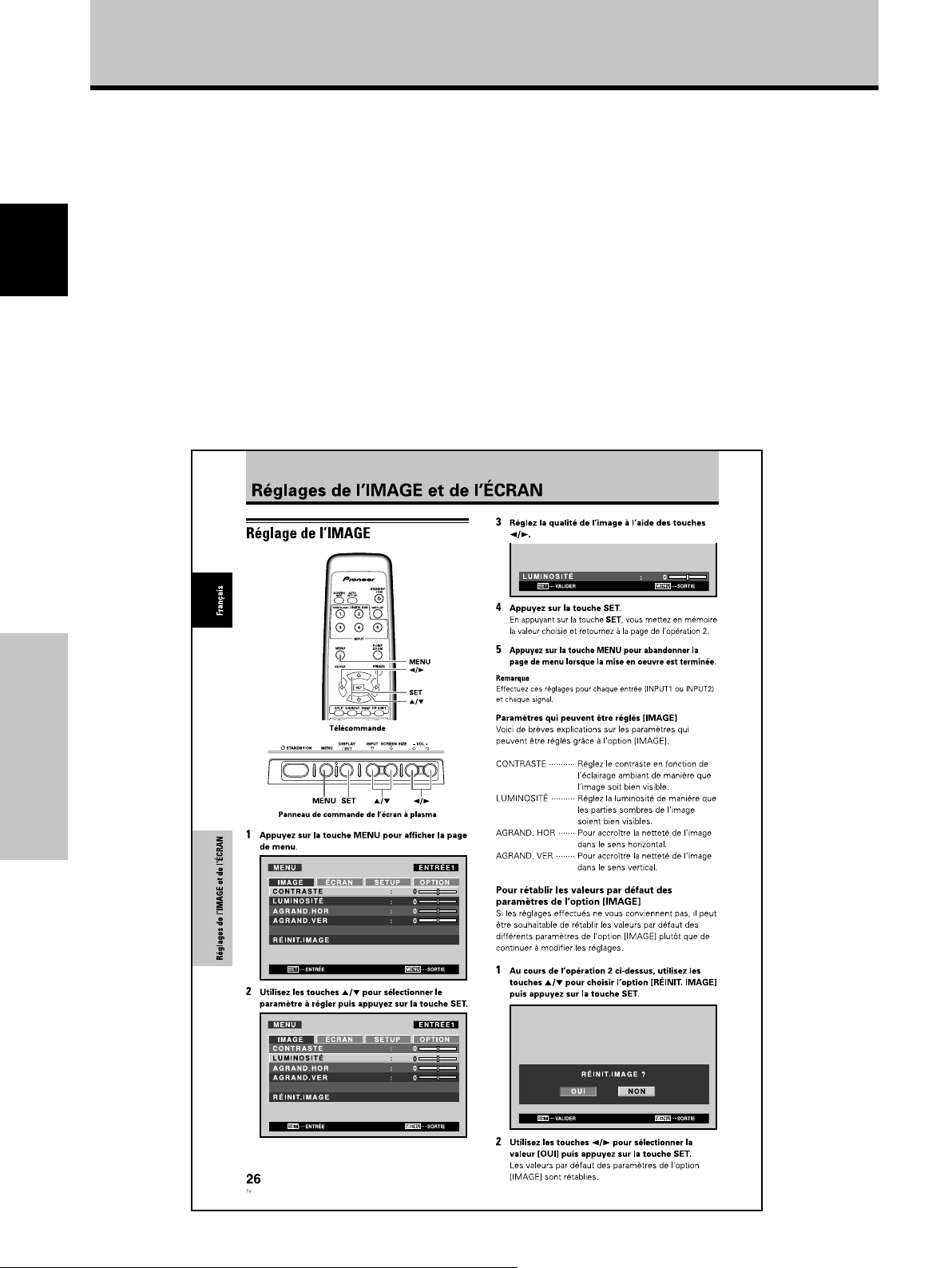
Avant de commencer
Description des modes
opératoires
Chaque opération est décrite en suivant son ordre
particulier. Les instructions de fonctionnement font
référence aux commandes, présentes sur la
télécommande, à l’exception des touches qui ne se
trouvent que sur l’écran à plasma proprement dit.
Lorsque des commandes équivalentes se trouvent à la
Français
fois sur l’écran à plasma et sur la télécommande, celles
de l’appareil principal peuvent être utilisées également.
Les illustrations suivantes sont un exemple des
démarches réelles utilisées pour la section “Réglage de
l’IMAGE”. Les exemples sont fournis pour vous
permettre de vérifier si les démarches se déroulent
correctement ou non.
Remarque
Les images d’écran illustrées dans ce manuel ne sont
présentées qu’à titre d’exemple. En pratique, certaines
différences apparaîtront en fonction de la rubrique affichée et de
son contenu, selon la source d’entrée et d’autres paramétrages
particuliers.
Avant de commencer
4
Fr
Page 65

Vérification des accessoires
fournis
Assurez-vous que les accessoires suivants font partie de
la fourniture.
Avant de commencer
8 2 noyaux en ferrite (PDP-427CMX : pour cordon
d’alimentation)
1 Cordon d’alimentation (2 m)
2 Télécommande
3 2 piles AA (R6)
4 Chiffon de nettoyage (pour l’écran)
Français
9 2 attaches de câble (PDP-427CMX)
0 2 supports pour l’écran (PDP-427CMX)
- 2 rondelles (petite) (PDP-427CMX)
5 3 colliers rapides
6 3 serre-câble
7 3 noyaux en ferrite (pour câbles audio)
= 2 boulons hexagonaux (M8 x 40 mm )
(PDP-427CMX)
~ Support pour télécommande (PDP-427CMX)
Utilisez ce support
pour y ranger la
télécommande. Si
vous fixez ce support à
l’arrière de l’écran,
veiller à ne pas
obstruer les ouïes
d’aération.
÷ Le présent mode d’emploi
÷ Carte de garantie
Avant de commencer
5
Fr
Page 66

Les différents organes et leurs rôles
Appareil
Français
Panneau de commande de
l’écran à plasma
STANDBY/ON MENU
DISPLAY
/ SET
Appareil
(PDP-507CMX/PDP-427CMX)
4
(PDP-607CMX)
4
PDP-507CMX
PDP-427CMX
STANDBY
ON
– VOL +INPUT SCREEN SIZE
2
1
3
6 7 8 95
Appareil
1 Capteur de télécommande
Dirigez le faisceau de télécommande vers ce capteur
(page 8).
2 Capteur de lumière ambiante
(PDP-507CMX/PDP-427CMX)
Il mesure le niveau de lumière à l’intérieur du local. Il
est activé lorsque l’option [ÉCON.ÉNERGIE] est
réglée sur [AUTO] (page 32).
3 Témoin STANDBY/ON (veille/marche)
Quand l’appareil fonctionne :
Les différents organes et leurs rôles
Le témoin s’allume en vert (page 20).
Le clignotement de ce témoin indique la présence de
messages d’erreur (page 41).
Ce témoin clignote en vert toutes les secondes
lorsque la fonction [GESTION D’ALIM.] est activée
(page 25).
Quand l’appareil est en mode de veille :
Le témoin s’allume en rouge (page 20).
Le clignotement de ce témoin indique la présence de
messages d’erreur (page 41).
4 Poignées
0
PDP-607CMX
13
Panneau de commande de l’écran à plasma
5 Touche STANDBY/ON (veille/marche)
Appuyez sur cette touche pour mettre l’écran en
service ou en veille (page 20).
6 Touche MENU
Appuyez sur cette touche pour ouvrir ou fermer les
menus s’affichant sur l’écran (pages 18 à 37).
7 Touche DISPLAY/SET (écran/validation)
Elle sert à valider les sélections sur les menus de
l’écran et à modifier les paramètres (pages 18 à 37).
Lorsqu’elle n’est pas indiquée par les menus sur
écran, cette touche permet d’afficher l’état de réglage
actuel (page 21).
8 Touche INPUT (’)
Sauf quand l’écran de menu est affiché, cette touche
agit pour changer l’entrée.
9 Touche SCREEN SIZE (‘)
Sauf quand l’écran de menu est affiché, cette touche
agit pour changer la taille de l’écran.
0 Touches VOL +/– (}/])
Lorsqu’elles ne servent pour à la sélection des
rubriques de menu sur l’écran, ces touches permettent
d’ajuster le volume sonore (pages 20 et 21).
6
Fr
Page 67

Télécommande
1
2
3
4
5
7
8
9
Manipulation du Télécommande
¶ Ne laissez pas tomber la télécommande et ne l’exposez
pas à de l’humidité.
¶ N’utilisez pas la télécommande en plein soleil, près d’un
appareil de chauffage, dans une atmosphère très humide.
¶ Si la portée de la télécommande a sensiblement diminué,
cela veut dire que les piles sont usagées. Remplacez alors
les piles dès que possible.
0
-
=
~
!
@6
#
$
%
Les différents organes et leurs rôles
1 Touche SCREEN SIZE
Appuyez sur cette touche pour choisir le format de
l’image (page 22).
2 Touches INPUT
Appuyez ces touches pour choisir le signal d’entrée
(page 20).
3 Touche MENU
Appuyez sur cette touche pour ouvrir ou fermer les
menus s’affichant sur l’écran (pages 18 à 37).
4 Touches ADJUST (5/∞/3/2)
Utilisez ces touches pour naviguer dans les menus et
choisir des valeurs de réglage (pages 18 à 37).
5 Touche SET
Appuyez sur cette touche pour définir une valeur ou
valider un choix (pages 18 à 37).
6 Touche SUB INPUT
Pendant l’affichage multi-écran, utilisez cette touche
pour changer les entrées au sous-écran (page 24).
7 Touche SPLIT
Appuyez sur cette touche pour passer à l’affichage
multi-écran (page 24).
8 Touche MUTING
Appuyez sur cette touche pour couper les sons (page
21).
9 Touche ID NO. SET
Elle est utilisée par les installateurs professionnels.
0 Touche AUTO SET UP
Si vous utilisez l’entrée d’un signal d’ordinateur, cette
touche ajuste automatiquement les paramètres
[POSITION], [HORLOGE] et [PHASE] (horloge/phase)
aux valeurs optimales (page 27).
- Touche STANDBY/ON ( )
Appuyez sur cette touche pour mettre l’écran en
service ou en veille (page 20).
= Touche DISPLAY
Appuyez sur cette touche pour afficher le nom de
l’entrée et de mode de fonctionnement actuels (page
21).
~ Touche POINT ZOOM
Utilisez cette touche pour choisir et agrandir une
partie de l’écran (page 23).
! Touche FREEZE
Quand la fonction d’écran de mémo est validée, une
image fixe est affichée sur le sous-écran (page 37).
@ Touche SWAP
Lors d’un affichage multi-écran, utilisez cette touche
pour permuter entre l’écran principal et le sous-écran
(page 24).
# Touche PIP SHIFT
A l’emploi du mode Image dans l’image avec un
affichage multi-écran, utilisez cette touche pour
déplacer la position du sous-écran (page 24).
$ Touches VOLUME (+/–)
Utilisez ces touches pour régler le niveau d’écoute
(pages 20 et 21).
% Touche CLEAR
Elle est utilisée par les installateurs professionnels.
Français
Les différents organes et leurs rôles
7
Fr
Page 68

Les différents organes et leurs rôles
Portée de fonctionnement de la
télécommande
Pour utiliser la télécommande, dirigez-la vers le capteur
situé sur la face avant de l’écran. La portée de la
télécommande va jusqu’à 7 mètres à un angle de 30˚
maximum de part et d’autre de l’axe du capteur.
Français
7 m
En cas de difficulté à l’emploi de la
télécommande
¶ La télécommande risque de ne pas fonctionner si son
Les différents organes et leurs rôles
faisceau est interrompu par un objet placé devant l’écran.
¶ La portée de la télécommande diminue à mesure que les
piles se déchargent. Remplacez le plus tôt possible les
piles dès qu’elles sont usées.
¶ L’écran à plasma émet des rayons infrarouges. Si une
platine vidéo ou un autre composant, contrôlé par une
télécommande à infrarouge, est placé près de cet appareil,
la réception des signaux de la télécommande peut en être
perturbée ou rendue impossible. Dans ce cas, éloignez le
composant par rapport à l’écran à plasma.
¶ Selon les conditions d’installation, les rayons infrarouges,
émis par l’écran à plasma, peuvent perturber le
fonctionnement ou réduire la portée de la télécommande.
La puissance des rayons infrarouges, émis par l’écran, varie
selon l’image affichée.
30˚
30˚
Capteur
Mise en place des piles de la
télécommande
Tout en appuyant sur le couvercle, faitesle glisser dans le sens de la flèche.
2 piles AA (R6)
Piles designées
Utilisez des piles de format AA (R6) ou AA (LR6).
ATTENTION
¶ N’utilisez pas de piles autres que celles qui sont
désignées et ne mélangez pas des piles usées et des
neuves, car une rupture ou une fuite d’électrolyte pourrait
en résulter, ce qui présenterait un risque d’incendie, de
blessure ou de contamination.
¶ Lors de la mise en place des piles dans la télécommande,
insérez-les en faisant correspondre leurs polarités (+) et
(–) avec celles indiquées sur le schéma. Une mise en
place incorrecte des piles peut entraîner leur rupture ou
une fuite d’électrolyte, ce qui présenterait un risque
d’incendie, de blessure ou de contamination.
¶ Ne chauffez pas et ne démontez pas les piles, ne les jetez
pas dans un feu ou dans l’eau, car une rupture ou une fuite
d’électrolyte pourrait en résulter, ce qui présenterait un
risque d’incendie, de blessure ou de contamination.
¶ Si vous prévoyez de ne pas utiliser la télécommande
pendant une longue durée, retirez-en les piles et rangezles séparément. Si des piles sont laissées à l’intérieur de
la télécommande, leur électrolyte pourrait suinter, ce qui
présenterait un risque d’incendie, de blessure ou de
contamination.
Lorsque vous diposez de piles / batteries usées,
veuillez vous conformer aux normes
gouvernementales ou environnementales en
vigueur dans votre pays ou région.
D3-4-2-3-1_Fr
8
Fr
Page 69

Les différents organes et leurs rôles
Panneau de raccordement (PDP-607CMX)
Le panneau de raccordement comporte deux prises d’entrée vidéo et une prise de sortie vidéo. Des prises d’entrée/sortie
audio et de sortie de haut-parleurs sont également prévues. Pour des explications sur les branchements, consultez les
pages indiquées entre parenthèses.
=-
Français
IN OUT
COMBINATION
RS-232C
1 COMBINATION IN/OUT
Ne branchez jamais un composant sur ces prises
sans consulter au préalable le technicien
d’installation Pioneer.
Ces prises sont utilisées pour les réglages de
configuration de l’écran à plasma.
2 Borne SPEAKER (R)
Pour le raccordement à l’enceinte droite.
Cette enceinte doit présenter une impédance
comprise entre
6 Ω
et 1
6 Ω (page 15).
3 Borne SPEAKER (L)
Pour le raccordement à l’enceinte gauche. Cette enceinte
doit présenter une impédance comprise entre
1
6 Ω
(page 15).
6 Ω
4 RS-232C
Ne branchez jamais un composant sur cette prise
sans consulter au préalable le technicien
d’installation Pioneer.
Cette prise est utilisée pour les réglages de
configuration de l’écran à plasma.
5 AUDIO (OUTPUT) (Mini-prise stéréo)
Utilisez cette sortie pour appliquer à un amplificateur
audiovisuel ou un appareil similaire, les sons provenant
de l’appareil source qui est relié à cet écran à plasma.
Remarque : Aucun son n’est produit au niveau de la prise
AUDIO (OUTPUT) lorsque l’interrupteur MAIN POWER est
réglé sur OFF (hors tension) ou ON (veille) (page 15).
6 AUDIO (INPUT1) (Mini-prise stéréo)
Utilisez cette prise pour disposer des sons appliqués
sur INPUT1.
INPUT1
OUTPUT INPUT2
AUDIO
AUDIO AUDIO
ANALOG RGB OUT
(D-Sub)
INPUT1
ANALOG RGB IN
(D-Sub)
INPUT2
DIGITAL RGB
(DVI-D)
0432158967
Branchez sur cette prise la sortie son de l’appareil relié
à INPUT1 (page 15).
7 AUDIO (INPUT2) (Mini-prise stéréo)
Utilisez cette prise pour disposer des sons appliqués
sur INPUT2.
Branchez sur cette prise la sortie son de l’appareil relié
à INPUT2 (page 15).
8 ANALOG RGB OUT (INPUT1)
(mini-prise D-sub à 15 broches)
Utilisez la prise ANALOG RGB OUT (INPUT1) pour
appliquer le signal vidéo sur un monite ur extérieur ou
Les différents organes et leurs rôles
un autre appareil.
et
Remarque : Le signal vidéo n’est pas présent sur la prise
ANALOG RGB OUT (INPUT1) lorsque l’écran à plasma est
hors tension ou en veille (page 14).
9 ANALOG RGB IN (INPUT1)
(mini-prise D-sub à 15 broches)
Utilisez ces prises pour le branchement d’un
ordinateur personnel (PC) ou d’un appareil similaire.
Choisissez la prise en fonction de la nature du signal
fourni par l’appareil connecté (page 14).
0 DIGITAL RGB (INPUT2) (prise DVI-D)
A utiliser pour raccorder un ordinateur.
Remarque : Cet appareil ne prend pas en compte l’affichage
de signaux vidéo protégés contre la copie (page 14).
- AC IN
Utilisez cette prise pour le branchement de la fiche du
cordon d’alimentation fourni (page 16).
= Interrupteur MAIN POWER
Utilisez cet interrupteur pour mettre l’écran à plasma
sous tension ou hors tension.
9
Fr
Page 70

Les différents organes et leurs rôles
Panneau de raccordement (PDP-507CMX)
Le panneau de raccordement comporte deux prises d’entrée vidéo et une prise de sortie vidéo. Des prises d’entrée/sortie
audio et de sortie de haut-parleurs sont également prévues.
Pour des explications sur les branchements, consultez les pages indiquées entre parenthèses.
Français
=-
21 8 9 03567
1 Borne SPEAKER (R)
Pour le raccordement à l’enceinte droite.
Cette enceinte doit présenter une impédance
comprise entre
6 Ω
et 1
6 Ω (page 15).
2 Borne SPEAKER (L)
Pour le raccordement à l’enceinte gauche. Cette enceinte
doit présenter une impédance comprise entre
1
6 Ω
(page 15).
3 COMBINATION IN/OUT
Ne branchez jamais un composant sur ces prises
sans consulter au préalable le technicien
Les différents organes et leurs rôles
d’installation Pioneer.
Ces prises sont utilisées pour les réglages de
configuration de l’écran à plasma.
4 RS-232C
Ne branchez jamais un composant sur cette prise
sans consulter au préalable le technicien
d’installation Pioneer.
Cette prise est utilisée pour les réglages de
configuration de l’écran à plasma.
5 AUDIO (OUTPUT) (Mini-prise stéréo)
Utilisez cette sortie pour appliquer à un amplificateur
audiovisuel ou un appareil similaire, les sons provenant
de l’appareil source qui est relié à cet écran à plasma.
Remarque : Aucun son n’est produit au niveau de la prise
AUDIO (OUTPUT) lorsque l’interrupteur MAIN POWER est
réglé sur OFF (hors tension) ou ON (veille) (page 15).
6 AUDIO (INPUT1) (Mini-prise stéréo)
Utilisez cette prise pour disposer des sons appliqués
sur INPUT1.
10
Fr
IN OUT
COMBINATION
6 Ω
INPUT1
RS-232C
OUTPUT INPUT2
AUDIO
AUDIO AUDIO
ANALOG RGB OUT
(D-Sub)
INPUT1
ANALOG RGB IN
(D-Sub)
INPUT2
DIGITAL RGB
(DVI-D)
4
Branchez sur cette prise la sortie son de l’appareil relié
à INPUT1 (page 15).
7 AUDIO (INPUT2) (Mini-prise stéréo)
Utilisez cette prise pour disposer des sons appliqués
sur INPUT2.
Branchez sur cette prise la sortie son de l’appareil relié
et
à INPUT2 (page 15).
8 ANALOG RGB OUT (INPUT1)
(mini-prise D-sub à 15 broches)
Utilisez la prise ANALOG RGB OUT (INPUT1) pour
appliquer le signal vidéo sur un monite ur extérieur ou
un autre appareil.
Remarque : Le signal vidéo n’est pas présent sur la prise
ANALOG RGB OUT (INPUT1) lorsque l’écran à plasma est
hors tension ou en veille (page 14).
9 ANALOG RGB IN (INPUT1)
(mini-prise D-sub à 15 broches)
Utilisez ces prises pour le branchement d’un
ordinateur personnel (PC) ou d’un appareil similaire.
Choisissez la prise en fonction de la nature du signal
fourni par l’appareil connecté (page 14).
0 DIGITAL RGB (INPUT2) (prise DVI-D)
A utiliser pour raccorder un ordinateur.
Remarque : Cet appareil ne prend pas en compte l’affichage
de signaux vidéo protégés contre la copie (page 14).
- AC IN
Utilisez cette prise pour le branchement de la fiche du
cordon d’alimentation fourni (page 16).
= Interrupteur MAIN POWER
Utilisez cet interrupteur pour mettre l’écran à plasma
sous tension ou hors tension.
Page 71

Les différents organes et leurs rôles
Panneau de raccordement (PDP-427CMX)
Le panneau de raccordement comporte deux prises d’entrée vidéo et une prise de sortie vidéo. Des prises d’entrée/sortie
audio et de sortie de haut-parleurs sont également prévues. Pour des explications sur les branchements, consultez les
pages indiquées entre parenthèses.
=-09
Français
IN OUT
COMBINATION
13
RS-232C
2
1 COMBINATION IN/OUT
Ne branchez jamais un composant sur ces prises
sans consulter au préalable le technicien
d’installation Pioneer.
Ces prises sont utilisées pour les réglages de
configuration de l’écran à plasma.
2 RS-232C
Ne branchez jamais un composant sur cette prise
sans consulter au préalable le technicien
d’installation Pioneer.
Cette prise est utilisée pour les réglages de
configuration de l’écran à plasma.
3 AUDIO (OUTPUT) (Mini-prise stéréo)
Utilisez cette sortie pour appliquer à un amplificateur
audiovisuel ou un appareil similaire, les sons provenant
de l’appareil source qui est relié à cet écran à plasma.
Remarque : Aucun son n’est produit au niveau de la prise
AUDIO (OUTPUT) lorsque l’interrupteur MAIN POWER est
réglé sur OFF (hors tension) ou ON (veille) (page 15).
4 AUDIO (INPUT1) (Mini-prise stéréo)
Utilisez cette prise pour disposer des sons appliqués
sur INPUT1.
Branchez sur cette prise la sortie son de l’appareil relié
à INPUT1 (page 15).
5 AUDIO (INPUT2) (Mini-prise stéréo)
Utilisez cette prise pour disposer des sons appliqués
sur INPUT2.
Branchez sur cette prise la sortie son de l’appareil relié
à INPUT2 (page 15).
INPUT1
OUTPUT INPUT2
AUDIO
AUDIO AUDIO
ANALOG RGB OUT
(D-Sub)
INPUT1
ANALOG RGB IN
(D-Sub)
INPUT2
DIGITAL RGB
(DVI-D)
6 7 845
6 ANALOG RGB OUT (INPUT1)
(mini-prise D-sub à 15 broches)
Utilisez la prise ANALOG RGB OUT (INPUT1) pour
appliquer le signal vidéo sur un monite ur extérieur ou
un autre appareil.
Remarque : Le signal vidéo n’est pas présent sur la prise
ANALOG RGB OUT (INPUT1) lorsque l’écran à plasma est
hors tension ou en veille (page 14).
7 ANALOG RGB IN (INPUT1)
(mini-prise D-sub à 15 broches)
Utilisez ces prises pour le branchement d’un
ordinateur personnel (PC) ou d’un appareil similaire.
Choisissez la prise en fonction de la nature du signal
fourni par l’appareil connecté (page 14).
8 DIGITAL RGB (INPUT2) (prise DVI-D)
A utiliser pour raccorder un ordinateur.
Remarque : Cet appareil ne prend pas en compte l’affichage
de signaux vidéo protégés contre la copie (page 14).
9 Borne SPEAKER (R)
Pour le raccordement à l’enceinte droite.
Cette enceinte doit présenter une impédance
comprise entre
6 Ω
et 1
6 Ω (page 15).
0 Borne SPEAKER (L)
Pour le raccordement à l’enceinte gauche. Cette enceinte
doit présenter une impédance comprise entre
1
6 Ω
(page 15).
6 Ω
- AC IN
Utilisez cette prise pour le branchement de la fiche du
cordon d’alimentation fourni (page 16).
= Interrupteur MAIN POWER
Utilisez cet interrupteur pour mettre l’écran à plasma
sous tension ou hors tension.
Les différents organes et leurs rôles
et
11
Fr
Page 72
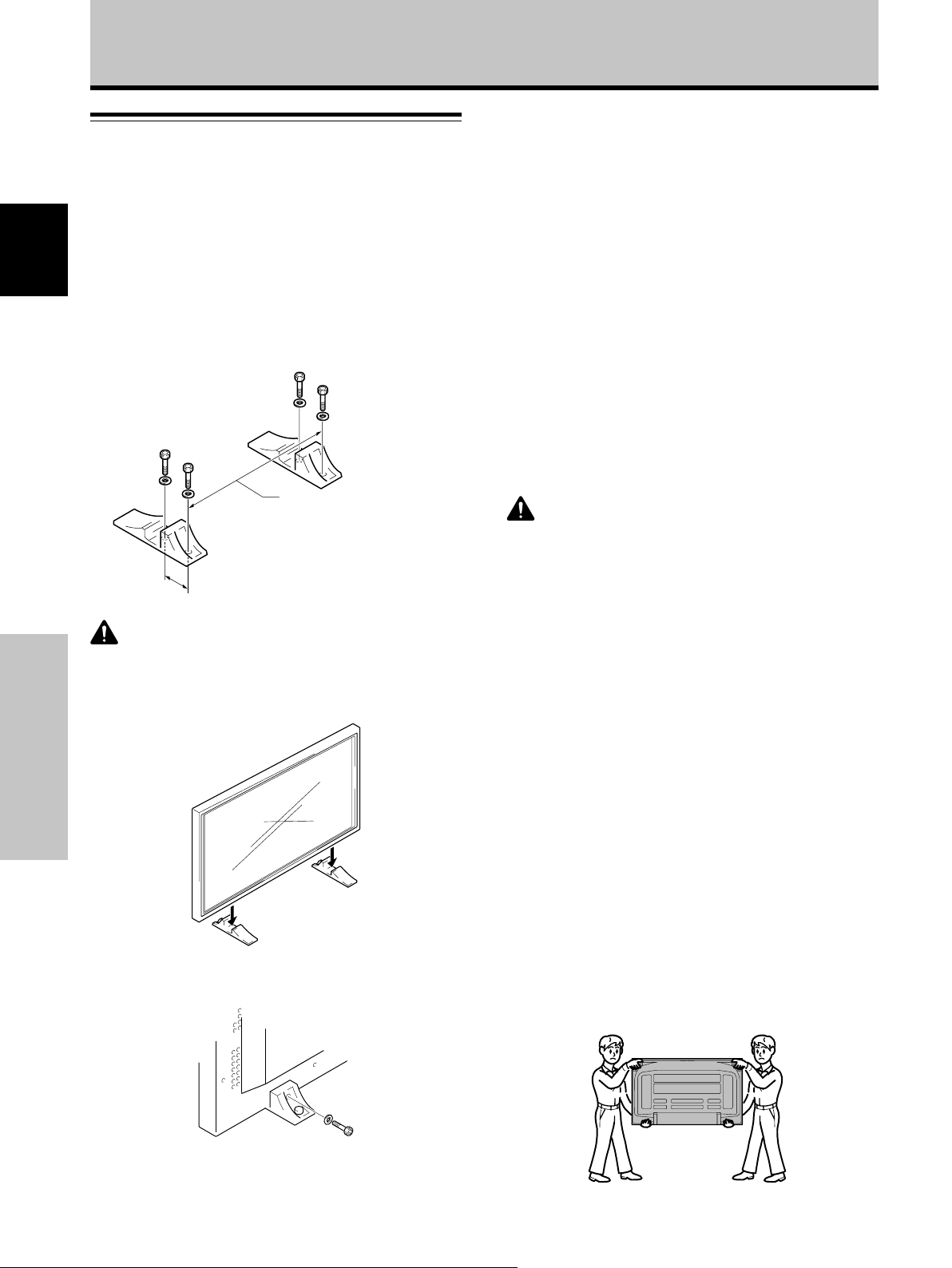
Installation et raccordements
Installation de l’écran à plasma
Installation de l’écran à plasma sur les supports
fournis (PDP-427CMX)
Fixez les supports sur la surface d’installation.
Utilisez des boulons M8 disponibles dans le commerce,
dont la longueur est supérieure de 25 mm à l’épaisseur
Français
de la surface d’installation.
1 Au moyen de boulons M8 disponibles dans le
commerce, assurez la fixation des supports fournis
à la surface d’installation préalablement percées
de 4 trous convenables.
Avant
517
mm
(Pas de vis d’orifice du
Arrière
Installez toujours les supports d’écran
fournis en tenant compte des dimensions
110 mm
indiquées sur l’illustration qui
accompagne l’appareil.
ATTENTION
Assurez-vous d’utiliser un boulon M8 (pas = 1,25 mm). (Seule
cette taille de boulon peut être utilisée.)
2 Posez l’écran à plasma dans les supports.
Installation et raccordements
3 Assurez la fixation de l’écran à plasma au moyen
des rondelles et des boulons hexagonaux fournis.
boulon)
Installation à l’aide du support PIONEER et
d’autres appliques de montage en option
÷ Veuillez demander l’installation ou le montage de cet appareil
par un spécialiste compétent ou le revendeur chez qui vous
l’avez acheté.
Accrochage de l’écran à plasma à un mur
L’écran à plasma possède des perçages destinés à
permettre sa fixation sur un mur, etc. Les perçages
prévus sont indiqués sur l’illustration fournie.
÷ L’écran à plasma doit être maintenu en 4 points
(minimum) placés au-dessus et au-dessous de l’axe
horizontal, et à droite et à gauche de l’axe vertical.
÷ Pour les perçages “a”, utilisez des boulons assez longs
pour être insérés entre 12 mm et 18 mm dans l’unité
principale à partir de la surface de fixation.
Reportez-vous à la vue de côté sur l’illustration fournie.
÷ L’écran à plasma est muni d’une vitre qui interdit sa
pose sur une surface qui n’est pas plane.
ATTENTION
÷ Utilisez uniquement les supports et appliques de montage
désignés par Pioneer. L’appareil risque de tomber, d’être
endommagé et de subir des défaillances si des articles non
recommandés sont utilisés.
÷ Assemblez correctement les supports et appliques de
montage conformément aux explications fournies ou autres
instructions d’installation applicables.
÷ Au moins deux personnes doivent travailler ensemble lors de
l’installation ou du déplacement de cet appareil.
÷ L’endroit d’installation choisi doit être suffisamment solide
pour soutenir le poids de cet appareil. Il doit être stable, plat et
horizontal. Installé dans un autre endroit, l’appareil pourrait
tomber et être endommagé.
÷ Après l’installation de l’appareil, prenez les dispositions
nécessaires pour éviter sa chute. Une négligence sur ce point
pourrait entraîner la chute de l’appareil, des blessures et des
dégâts.
÷ En cas d’installation sur une paroi, le travail doit être confié à
un technicien professionnel, disposant des connaissances et
compétences techniques requises. Consultez votre revendeur
pour obtenir davantage d’informations. Une installation
inadéquate ou insuffisante peut entraîner des accidents, des
dégâts, voire des blessures.
÷ Seul un technicien spécialisé en installation ou un personnel
de service sera habilité à détacher ou à rattacher les poignées.
÷ Lors du déplacement de l’écran, il doit toujours être transporté
par deux personnes, saisissant les poignées arrière comme
illustré ici.
N’essayez jamais de déplacer l’écran à plasma en ne le tenant
que par une de ses poignées.
12
Fr
Pour serrer, utilisez
une clé hexagonale
de 6 mm.
Page 73

Installation et raccordements
Perçage b*
Perçage a
Perçage b*
Perçage a
Ouïes d’aération (ventilateur)
Axe
Vue arrière (PDP-607CMX)
Ouïes d’aération (ventilateur)
Perçage b*
Perçage a
Perçage b*Perçage b*
Perçage b*
Perçage a
Axe
Appareil
Perçage b
Vue de côté
Surface de pose
Fixation, etc.
Perçage a
Boulon
12 mm à 18 mm
Vis fournie avec le
haut-parleur (vendu
séparément)
Surface de pose
Fixation, etc.
Français
Perçage a
Perçage b*
Perçage a
Perçage a
Perçage a Perçage a
Axe
Vue arrière (PDP-507CMX)
Ouïes d’aération (ventilateur)
Perçage b*
Perçage a
Axe
Perçage b*Perçage b*
Appareil
Perçage b
Vue de côté
Perçage a
Boulon
12 mm à 18 mm
Vis fournie avec le
haut-parleur (vendu
séparément)
Installation et raccordements
Surface de pose
Fixation, etc.
Perçage a
Boulon
12 mm à 18 mm
Axe
Appareil
* Uniquement pour haut-parleur
Axe
Vue arrière (PDP-427CMX)
Vis fournie avec le
Perçage b
Perçage b*Perçage b*
Vue de côté
haut-parleur (vendu
séparément)
13
Fr
Page 74

Installation et raccordements
Raccordement à un ordinateur
personnel
La méthode de raccordement dépend du type de
l’ordinateur. Avant d’effectuer les raccordements, veuillez
lire attentivement le mode d’emploi de l’ordinateur.
Français
Avant tout raccordement veillez à ce que l’écran à plasma
et l’ordinateur soient tous deux hors tension.
Pour le raccordement à ANALOG RGB OUT (INPUT1)
ANALOG RGB OUT
(D-Sub)
INPUT1
ANALOG RGB IN
(D-Sub)
Raccordement de INPUT1
Raccordez le connecteur d’entrée D-sub de l’écran au
connecteur de sortie D-sub (RVB analogique) de
l’ordinateur.
Ce connecteur prend en compte également les signaux G
ON SYNC (sortie à signal vert combiné au signal de
synchronisation) et SYNC composites (sortie à signaux
combinés de synchronisation horizontale et verticale).
Pour le raccordement à ANALOG RGB IN (INPUT1)
ANALOG RGB OUT
(D-Sub)
INPUT1
ANALOG RGB IN
(D-Sub)
Vers un moniteur extérieur.
Cet écran à plasma est prévu pour que le signal vidéo
puisse être appliqu à un moniteur ou un autre appareil à
partir de la prise ANALOG RGB OUT (INPUT1).
Remarque
Le signal vidéo n’est pas présent sur la prise ANALOG RGB OUT
(INPUT1) lorsque l’écran à plasma est hors tension ou en veille.
Raccordement de INPUT2
Un ordinateur, muni d’une sortie DVI (signal RVB
numérique) peut être raccordé au connecteur DVI de
l’écran à plasma.
INPUT2
DIGITAL RGB
(DVI-D)
Installation et raccordements
Branchez le câble entre la prise d’entrée de l’écran à
plasma et la prise de sortie de l’ordinateur personnel.
Serrez soigneusement les vis des connecteurs à chaque
extrémité du câble.
Lorsque que les raccordements sont terminés, un réglage
général à l’aide des menus sur écran est nécessaire.
Reportez-vous aux pages 18 à 19 pour les détails.
Remarque
Selon le type de l’ordinateur, un adaptateur (fourni avec
l’ordinateur ou vendu séparément) peut être nécessaire pour
effectuer le raccordement ci-dessus.
Veuillez consulter le mode d’emploi de l’ordinateur ou le revendeur.
NOTICE
¶ La prise INPUT1 prend en compte les composants à approche
“Plug & Play” (VESA DDC 1/2B) de Microsoft. Consultez le
Supplément 2-1/2 (page 49) lors de connexions sur INPUT1.
¶ Consultez le Supplément 1-1/4, -3/4 (pages 43 et 46) pour des
informations sur les signaux et les formats d’affichage pris en
compte par INPUT1.
14
Fr
Lorsque que les raccordements sont terminés, un réglage
général à l’aide des menus sur écran est nécessaire.
Reportez-vous aux pages 18 à 19 pour les détails.
Remarques
¶ Utilisez un câble DVI-D à 24 broches (numérique seulement)
pour le raccordement.
¶ Cet appareil n’autorise pas l’affichage de signaux vidéo
protégés contre la copie.
NOTICE
¶ La prise INPUT2 prend en compte les composants à approche
“Plug & Play” (VESA DDC 2B) de Microsoft. Consultez le
Supplément 2-2/2 (page 49) lors de connexions sur INPUT2.
¶ Consultez le Supplément 1-2/4, -4/4 (pages 44 et 47) pour des
informations sur les signaux et les formats d’affichage pris en
compte par INPUT2.
Page 75
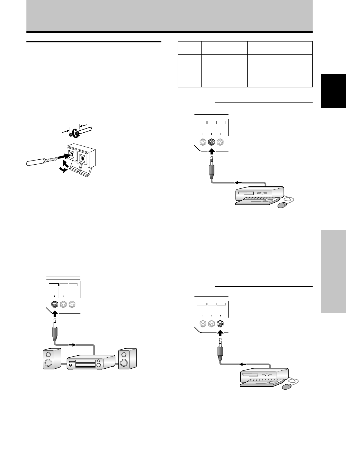
Installation et raccordements
Raccordements audio
Avant tout raccordement veillez à ce que les appareils
soient tous deux hors tension.
Raccordement des enceintes
Cet écran à plasma est doté de prises de sortie pour
enceintes acoustiques (non fournies) qui ont été
spécialement conçues pour fonctionner avec l’écran.
Avant d’effectuer un raccordement, reportez-vous aux
illustrations.
Remarques
÷ Après avoir branché un conducteur, tirez doucement sur le câble
pour vous assurer que son âme est fermement immobilisée par
la prise. Des branchements relâchés peuvent entraîner des
parasites ou une interruption des sons.
÷ Veillez à ce que les brins des câbles ª et · des enceintes ne
ressortent pas des prises au point de se toucher et de
provoquer un court-circuit. Ceci produirait une charge
excessive sur l’écran plasma qui subirait un
dysfonctionnement ou s’arrêterait.
12 mm
Torsadez les
brins mis à nu.
Soulevez la languette
puis introduisez le
conducteur. Abaissez la
languette pour
maintenir le conducteur
en place.
Entrée
vidéo
INPUT1
INPUT2
Entrée audio Sortie son
Prise stéréo (G/D)
miniformat
Prise stéréo (G/D)
miniformat
Les sons provenant de l’entrée
vidéo choisie sont présents sur
• les bornes SPEAKER (G/D)
• la prise stéréo (G/D)
miniformat.
Raccordement audio pour un appareil (ordinateur)
relié à INPUT1
INPUT1
OUTPUT INPUT2
AUDIO
AUDIO AUDIO
Un câble stéréo à minifiche peut servir pour raccorder la
sortie audio du composant, raccordé sur INPUT1, à la
prise d’entrée stéréo (G/D) miniformat AUDIO (INPUT1)
de l’écran à plasma.
Français
Raccordement au connecteur de sortie audio
Utilisez une minifiche stéréo pour raccorder la prise de
sortie stéréo (G/D) miniformat AUDIO (OUTPUT) à un
amplificateur audiovisuel ou un autre composant.
INPUT1
OUTPUT INPUT2
AUDIO
AUDIO AUDIO
Raccordements aux entrées audio de cet écran à
plasma
Cet écran à plasma est doté de deux entrées audio et
d’une sortie audio. Le tableau qui suit donne pour chaque
entrée vidéo les entrées audio correspondantes.
Le son est fourni au niveau de la prise stéréo (G/D)
miniformat AUDIO (OUTPUT) et des bornes SPEAKER (G/
D) selon la sélection de l’entrée vidéo.
Raccordement audio pour un appareil (ordinateur)
relié à INPUT2
INPUT1
OUTPUT INPUT2
AUDIO
AUDIO AUDIO
Un câble stéréo à minifiche peut servir pour raccorder la
sortie audio du composant, raccordé sur INPUT2, à la
prise d’entrée stéréo (G/D) miniformat AUDIO (INPUT2)
de l’écran à plasma.
Installation et raccordements
Le son est fourni au niveau de la prise stéréo (G/D)
miniformat AUDIO (OUTPUT) et des bornes SPEAKER (G/
D) selon la sélection de l’entrée vidéo.
15
Fr
Page 76
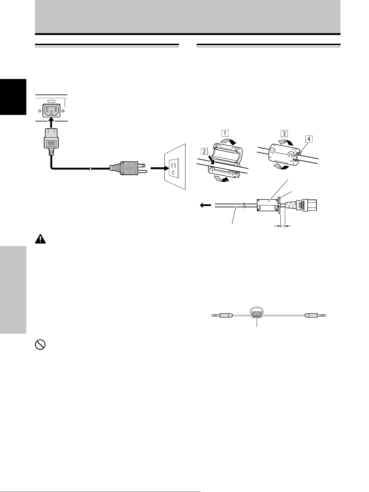
Installation et raccordements
Raccordement du cordon
d’alimentation
Branchez le cordon d’alimentation après que tous les
raccordements ont été réalisés.
Français
Installation et raccordements
AC IN
1
2
1 Branchez une extrémité du cordon d’alimentation
sur cet écran à plasma.
2 Branchez l’autre extrémité du cordon sur une prise
secteur.
ATTENTION
÷ Utilisez uniquement le cordon d’alimentation fourni.
÷ La prise de sortie secteur murale utilisée pour alimenter
l’appareil en électricité doit être placé le plus près possible de
l’appareil et facilement à la portée de l’utilisateur.
Si toutefois il est nécessaire de couper l’alimentation de
l’appareil, commutez d’abord l’interrupteur d’alimentation
général de l’appareil sur arrêt et débranchez le cordon
d’alimentation de sa prise de sortie secteur murale.
÷ Pour l’écran plasma, utilisez un cordon d’alimentation à trois
broches, muni d’une borne de terre.
Veillez à ce que la prise possède une broche de mise à la terre
et qu’elle soit convenablement câblée. En cas d’utilisation d’un
adaptateur, le conducteur de masse doit tout de même être
relié à la terre.
Fixation des noyaux en ferrite
Cordon d’alimentation (PDP-427CMX)
Fixez les noyaux en ferrite fournis comme accessoires sur
les deux bouts de connexion du cordon d’alimentation
comme indiqué sur l’illustration. Utilisez l’attache de câble
fournie pour éviter un glissement du noyau en ferrite sur
le câble.
Si vous ne faites pas cela, le moniteur ne sera pas
conforme aux normes obligatoires FCC.
Noyau en ferrite
Attache de câble
À la prise
secteur
Cordon d’alimentation
Le plus près possible
Câble audio
Concernant le câble audio, fixer le noyau en ferrite fourni.
Enrouler le câble audio (non fourni) autour du noyau en
ferrite une fois, puis fixer le loquet.
Si vous ne faites pas cela, le moniteur ne sera pas
conforme aux normes obligatoires FCC.
Câble audio (non fourni)
Noyau en ferrite
À la prise AC IN
NON!
Alimentez l’écran à plasma à partir de la tension prescrite
(100 V à 120 V CA, 50 Hz/60 Hz); tout autre tension peut
provoquer un incendie ou une secousse électrique.
16
Fr
Page 77

Comment faire cheminer les câbles
Des colliers rapides sont fournis avec cet écran à plasma
pour grouper les câbles ensemble. Après raccordements
des appareils, procédez aux opérations qui suivent.
2
1
Installation et raccordements
* Vue de l’arrière de l’écran.
Français
1 Groupez les câbles en utilisant les colliers rapides
fournis.
Introduisez la partie 1 dans un des perçages à
l’arrière de l’écran à plas ma puis insérez 2 à l’arrière
de 1 pour assurer la fixation.
Les colliers rapides sont conçus pour que l’ouverture
soit difficile. Fermez-les soigneusement.
2 Liez les câbles et assurez leur maintien au moyen
des serre-câble fournis.
Veillez à ce que les bouts des câbles ne subissent pas
une tension excessive.
Remarque
Les câbles peuvent cheminer d’un côté ou de l’autre.
Fixation des colliers rapides à l’écran à plasma
Engagez les colliers rapides dans les trous 4 repérés par “‡” sur l’illustration ci-dessous.
PDP-607CMX
Utilisez les trous indiqués par le signe & selon les besoins.
PDP-507CMX
PDP-427CMX
Installation et raccordements
Pour retirer les colliers rapides
A l’aide d’une pince, tordez le collier de 90° puis tirez-le
vers vous. Avec le temps, le collier peut se détériorer et il
peut être nécessaire de la remplacer après que vous
l’avez retiré.
* Vue de l’arrière de l’écran.
17
Fr
Page 78

Paramétrages du système
Réglage de la langue d’affichage
4 Utilisez les touches 2/3 pour sélectionner
[OPTION].
sur écran
L’anglais a été défini par défaut comme langue des
affichages sur écran. Pour passer à une autre langue, le
réglage doit être modifié. Procédez comme suit pour
effectuer ce changement.
Français
STANDBY/
ON
MENU
2/3
SET
5/∞
Télécommande
STANDBY/ON MENU
Panneau de commande de l’écran à plasma
1 Réglez l’interrupteur MAIN POWER du panneau
arrière sur ON (marche).
Paramétrages du système
Le témoin STANDBY/ON du panneau avant s’allume
en rouge.
2 Appuyez sur la touche STANDBY/ON pour mettre
l’écran sous tension.
Le témoin STANDBY/ON du panneau avant s’allume
en vert.
3 Appuyez sur la touche MENU pour obtenir la page
de menu.
MENU INPUT1
PICTURE
CONTRAST
BRIGHTNESS
H.ENHANCE
V.ENHANCE
PICTURE RESET
DISPLAY
/ SET
SET 5/∞
MENU
SCREEN SETUP OPTION
:
:
:
:
MENU INPUT1
PICTURE
LANGUAGE
ENERGY SAVE
TIMER SETTING
SCREEN MGT.
AUTO SETUP MODE
AUTO FUNCTION
PIP DETECT
SPLIT FREEZE
SET
SCREEN SETUP OPTION
ENTER
:ENGLISH
:STANDARD
:INACTIVE
:OFF
:ACTIVE
:OFF
MENU
EXIT
5 Utilisez les touches 5/∞ pour sélectionner
[LANGUAGE], puis appuyez sur la touche SET.
LANGUAGE ENGLISH
SET
– VOL +INPUT SCREEN SIZE
6
Utilisez les touches 2/3 pour sélectionner la langue
SET
:
MENU
EXIT
souhaitée.
A chaque pression sur les touches 2/3, les langues
2/3STANDBY/ON
disponibles changent dans l’ordre suivant :
3
ENGLISH
LANGUAGE FRANÇAIS
2
3 ITALIANO 2
SET
SET
3
FRANÇAIS
2 3
ESPAÑOL
3 DEUTSCH 2
:
MENU
2
EXIT
7 Lorsque la langue souhaitée est affichée, appuyez
0
0
0
0
sur la touche SET.
La langue sélectionnée sera mémorisée et l’écran
repassera à celui de l’étape 4.
8 Lorsque les réglages sont terminés, appuyez sur la
touche MENU pour revenir à la page d’écran
normale.
18
Fr
SET
ENTER
MENU
EXIT
Remarque
Lorsque la langue d’affichage sur écran a été réglée soit pour
INPUT1, soit pour INPUT2, elle sera la même pour l’autre entrée.
Page 79

Paramétrages après raccordement
Paramétrages du système
2 Utilisez les touches 2/3 pour sélectionner l’option
[SETUP].
Après le raccordement des appareils aux prises INPUT1
ou INPUT2, des réglages à l’aide des menus affichés sur
l’écran sont nécessaires.
Procédez aux opérations décrites ci-dessous et effectuez
les réglages en fonction des appareils connectés.
Mise en œuvre pour
[TYPE DE SIGNAL]
MENU
2/3
SET
5/∞
MENU ENTRÉE1
GESTION D'ALIM. :ARRÊT
TYPE DE SIGNAL
ÉCRAN SETUP OPTIONIMAGE
3 Utilisez les touches 5/∞ pour sélectionner l’option
[TYPE DE SIGNAL], puis appuyez sur la touche
SET.
MENU ENTRÉE1
AUTO
VALIDER
ÉCRAN SETUP OPTIONIMAGE
MENU
SORTIE
GESTION D'ALIM. :ARRÊT
TYPE DE SIGNAL
4
Utilisez les touches 2/3 pour sélectionner le signal
d’entrée.
TYPE DE SIGNAL
:
SET
Français
Télécommande
STANDBY/ON MENU
Panneau de commande de l’écran à plasma
DISPLAY
/ SET
– VOL +INPUT SCREEN SIZE
2/3MENU SET 5/∞
1 Appuyez sur la touche MENU pour afficher la page
de menu.
MENU ENTRÉE1
IMAGE
CONTRASTE
LUMINOSITÉ
AGRAND.HOR
AGRAND.VER
RÉINIT.IMAGE
SET
ÉCRAN SETUP OPTION
:
:
:
:
ENTRÉE
0
0
0
0
MENU
SORTIE
A chaque pression sur les boutons 2/3, la sélection
alterne comme suit :
3 AUTO
Autres 2
÷ AUTO .... Les signaux sont automatiquement
détectés en accord avec le tableau des
comptabilités de signal d’ordinateur
(pages 43 à 48).
÷ Autres ... Les résolutions utilisables sont affichées.
5 Appuyez sur la touche SET.
Le réglage est mémorisé et l’écran repasse à celui
illustré à l’étape 3.
6
Appuyez sur la touche MENU pour abandonner la
page de menu lorsque la mise en œuvre est terminée.
Remarque
Effectuez la mise en œuvre [TYPE DE SIGNAL] pour chaque
entrée (INPUT1 et INPUT2).
Paramétrages du système
19
Fr
Page 80

Fonctionnement
Choix de la source d’entrée
Cette section explique le fonctionnement de base. Nous
abordons, dans les pages qui suivent, la manière de
mettre sous tension, ou hors tension, l’écran à plasma, de
le mettre en service ou en veille, et de choisir un appareil
parmi ceux qui sont connectés.
Français
Avant tout, assurez-vous que:
÷ Vous avez effectué les raccordements entre l’écran à
plasma et l’ordinateur personnel, comme expliqué à la
section “Installation et raccordements” qui débute à la
page 12.
÷ Les réglages de mise en oeuvre ont été réalisés, pour
les appareils connectés à INPUT1 et INPUT2,
conformément à la section “Paramétrages du
système”, page 18.
Si aucun appareil n’est relié à ces prises, aucune mise
en oeuvre n’est requise.
STANDBY/
ON
INPUT
3 Appuyez sur la touche INPUT pour sélectionner
l’entrée.
÷ Si la page de menu est affichée, elle disparaît
lorsque le signal d’entrée est modifié.
÷ Si le signal fourni par l’ordinateur n’est pas accepté
par cet écran, le message suivant est affiché :
ENTRÉE1
ATTENTION
SIGNAL NON RECONNU
FH: 86.7kHz
FV: 88.5Hz
–
POL.H: –
POL.V: –
PLEIN ÉCRAN
4 Utilisez les touches VOLUME (+/–) pour ajuster le
volume sonore.
Si aucune signal sonore n’est appliqué à l’écran à
plasma, cette opération est inutile.
5 Lorsque vous avez fini de regarder les images,
appuyez sur la touche STANDBY/ON pour placer
l’écran à plasma en veille.
6 Réglez l’interrupteur MAIN POWER du panneau
arrière sur OFF.
Le témoin STANDBY/ON peut rester allumé pendant
quelques instants après la mise hors tension. Ceci
provient du courant électrique restant dans les circuits.
Fonctionnement
Télécommande
STANDBY/ON MENU
Panneau de commande de l’écran à plasma
DISPLAY
/ SET
VOLUME
[+/–]
VOL +/–INPUTSTANDBY/ON
1 Réglez l’interrupteur MAIN POWER du panneau
arrière sur ON (marche).
Le témoin STANDBY/ON du panneau avant s’allume
en rouge.
2 Appuyez sur la touche STANDBY/ON pour mettre
l’écran sous tension.
Le témoin STANDBY/ON du panneau avant s’allume
en vert.
Remarque
Ne laissez pas la même image affichée sur l’écran pendant une
longue période. Cela peut causer une détérioration de l’écran (on
parle de “brûlage” de l’écran) qui se traduit par la persistence de
cette image atténuée.
– VOL +INPUT SCREEN SIZE
20
Fr
Page 81
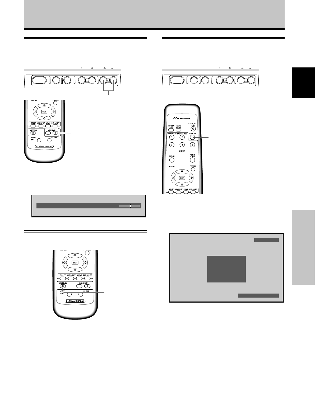
Fonctionnement
Réglage du volume sonore
Panneau de commande de l’écran à plasma
STANDBY/ON MENU
DISPLAY
/ SET
VOLUME
[+/–]
Télécommande
Appuyez sur les touches VOLUME.
Appuyez sur la touche [–] ou [+] pour réduire ou
augmenter le volume du son provenant des enceintes.
– VOL +INPUT SCREEN SIZE
VOL +/–
Vérification de l’état actuel
Panneau de commande de l’écran à plasma
STANDBY/ON MENU
DISPLAY
/ SET
DISPLAY/SET
DISPLAY
Télécommande
– VOL +INPUT SCREEN SIZE
Français
VOLUME
:
10
Coupure des sons
MUTING
Appuyez sur la touche MUTING de la
télécommande.
Appuyez une nouvelle fois sur la touche MUTING pour
rétablir les sons.
Utilisez les touches VOLUME + ou VOLUME – pour
régler le niveau d’écoute.
Appuyez sur la touche DISPLAY.
Le nom de l’entrée choisie, le format de l’image et les
fréquences de rafraîchissement seront affichés pendant 3
secondes environ.
ENTRÉE1
FH : 31.5kHz
FV : 60.0Hz
640X480
POL.H : NEGA
POL.V : POSI
POINT PAR POINT
Remarque
Il se peut que les fréquences de rafraîchissement affichées
soient légèrement différentes des valeurs réelles.
Fonctionnement
21
Fr
Page 82

Fonctionnement
Changement de la taille de l’écran
Cet écran à plasma est en mesure d’afficher des images
ayant des hauteurs et des largeurs différentes. Nous vous
conseillons de choisir le format correspondant le mieux à
la source vidéo. Bien que ces modes aient été imaginés
pour l’affichage d’une image sur grand écran, nous
Français
espérons que vous les emploierez en tenant compte des
intentions qui ont prévalu à leur choix.
Choix d’un format d’image
La taille de l’image affichée sur l’écran et le format d’écran
indiqué peuvent être réglés à un des quatre modes.
Appuyez sur la touche SCREEN SIZE pour
choisir le format.
Avec un signal d’entrée provenant d’un ordinateur
personnel
1 POINT PAR POINT
Le signal d’entrée et l’image sont dans un rapport point à
ligne de 1/1 et sont donc tout à fait fidèles à la source.
PDP-427CMX : Cet appareil est conçu avec des
éléments horizontement allongés. En conséquence,
l’image affichée apparaît plus allongée que celle du
signal d’entrée original.
2 4:3
L’image remplit l’écran autant que possible mais le format
n’est pas modifi.
Télécommande
STANDBY/ON MENU
Fonctionnement
Panneau de commande de l’écran à plasma
Le format d’image change comme suit chaque fois que la
touche SCREEN SIZE est actionnée.
3 POINT PAR POINT
4:3 2
Consultez le Tableau des compatibilités de signal
d’ordinateur (pages 43 à 48) pour des renseignements sur
les tailles d’écran, supportées par chaque format de signal.
Remarques
÷
Si vous utilisez un format grand écran tel que [PLEIN ÉCRAN]
pour afficher une image au format standard de 4/3, une portion
de l’image peut être coupée ou déformée.
÷ Sachez que si l’écran sert à des applications commerciales ou
des projections publiques, la sélection du format [PLEIN
ÉCRAN] peut entraîner une infraction aux droits d’auteur,
protégés par la législation.
÷ Lorsque le mode d’écran [POINT PAR POINT] ou [4:3] est
sélectionné, la position d’affichage est légèrement décalée à
chaque mise sous tension afin d’éviter une rémanence de
l’image sur l’écran.
DISPLAY
/ SET
SCREEN SIZE
ou
– VOL +INPUT SCREEN SIZE
3 PLEIN ÉCRAN
4:3 2
SCREEN
SIZE
A
3 PLEIN ÉCRAN
L’image a le format 16/9 et remplit l’écran.
A
22
Fr
Page 83

50
Agrandissement partiel de l’image
(POINT ZOOM)
Cet écran à plasma autorise un agrandissement de l’image
affichée. Lorsque l’image est agrandie, la zone de sa vision
peut être déplacée sur l’écran au moyen des touches 5/∞/
2/3.
¶ Il est possible de vérifier la plage de zoom disponible en
observant le sous-écran Plage de Zoom dans le coin
supérieur droit de l’écran principal (un signe “+” sera
affiché au centre). Le sous-écran Plage de Zoom est
affiché pendant 3 secondes environ chaque fois que la
touche POINT ZOOM, une des touches 5/∞/2/3 ou la
touche DISPLAY est actionnée.
Fonctionnement
À chaque pression sur la touche POINT ZOOM, le
rapport de zoom change dans l’ordre suivant :
3 LEVEL1 3 LEVEL2
LEVEL4 2 LEVEL3 2
÷ LEVEL1 .......... x1
÷ LEVEL2 .......... x1,5
÷ LEVEL3 .......... x2
÷ LEVEL4 .......... x3
2 Utilisez les touches 5/∞/2/3 pour déplacer
l’écran à la partie souhaitée de l’image.
Français
DISPLAY
MENU
POINT
ZOOM
5/∞/2/3
SET
1 Appuyez sur la touche POINT ZOOM de la
télécommande.
66.0
24
R12
24
10
84.3
R12
22.1
10
Remarques
¶ À l’emploi de la fonction POINT ZOOM, le format d’écran ne
peut pas être modifié.
¶ Lorsque l’écran à plasma est utilisé pour une activité à but
lucratif ou pour la présentation d’images en public, l’emploi de
la fonction Format d’écran pour comprimer ou élargir une
image peut entraîner une violation des copyrights des
détenteurs des images.
¶ Une nouvelle pression sur les touches POINT ZOOM et 5/∞/
2/3 changera le rapport de zoom et la position agrandie de
l’écran.
¶ Si le signal d’entrée change, si la page de menu est affichée et
que l’entrée est changée, ou si le mode multi-écran est
sélectionné, la fonction Agrandissement partiel de l’image
(POINT ZOOM) sera annulée.
Fonctionnement
10
22.1
Sous-écran Plage de Zoom
23
Fr
Page 84

Fonctionnement
Affichage multi-écran
La fonction Multi-écran de cet écran à plasma autorise
l’affichage simultané de deux entrées. L’affichage multiécran comprend deux modes : Côte à côte et Image dans
image.
Français
SPLIT
SUB INPUT
1 Appuyez sur la touche SPLIT de la télécommande.
À chaque pression sur la touche, l’affichage multiécran change dans l’ordre suivant :
3 Côte à côte
Image dans image 2ARRÊT 2
1 Côte à côte
L’écran principal apparaît sur la gauche et le sousécran sur la droite.
Fonctionnement
2 Image dans image
Le sous-écran est affiché dans un des quatre coins de
l’écran principal.
DISPLAY
FREEZE
PIP SHIFT
SWAP
66.0
24
10
2 Appuyez sur la touche SUB INPUT de la
télécommande pour sélectionner la source
d’entrée du sous-écran.
Pour permuter les entrées à l’écran principal et
au sous-écran :
Appuyez sur la touche SWAP de la télécommande.
¶ Lorsque le mode côte à côte est sélectionné :
Les côtés droit et gauche de l’affichage permutent. Ce
qui était affiché sur l’écran principal apparaît sur le sousécran et vice versa.
¶ Lorsque le mode Image dans image est sélectionné :
Ce qui était affiché sur l’écran principal apparaît en
format réduit sur le sous-écran et vice versa.
Pour changer la position du sous-écran en mode
Image dans image :
Appuyez sur la touche PIP SHIFT de la télécommande.
À chaque pression sur cette touche, la position du sousécran change dans l’ordre suivant :
3 Coin inférieur droit 3 Coin supérieur droit
Coin inférieur gauche 2 Coin supérieur gauche 2
Pour afficher l’entrée actuellement sélectionnée :
Appuyez sur la touche DISPLAY.
Si la touche DISPLAY est actionnée en mode Multi-écran,
l’écran principal et le sous-écran afficheront
respectivement leur entrée actuellement sélectionnée.
Remarques
¶ Lorsque l’écran à plasma est utilisé pour une activité à but lucratif
ou pour la présentation d’images en public, l’emploi de la fonction
Format d’écran pour comprimer ou élargir une image peut
entraîner une violation des copyrights des détenteurs des images.
¶ Si l’affichage multi-écran est laissé en service pendant
longtemps ou si le même affichage multi-écran est utilisé
quotidiennement de façon répétée et pendant de brèves
périodes, une image rémanente risque de se former sur l’écran.
¶ En fonction de la source utilisée, l’image peut sembler un peu
R12
22.1
sommaire lorsque vous utilisez le mode Côte à côte.
¶ Le mode multi-écran sera annulé si un menu est ouvert ou si la
fonction Agrandissement partiel de l’image (POINT ZOOM) est
utilisée.
¶ Le format d’écran ne peut pas être modifié pendant l’affichage
Multi-écran.
¶ Le son de l’entrée sélectionnée sur l’écran principalest fourni
lorsque vous utilisez la fonction Multi-écran.
24
Fr
66.0
R12
24
22.1
10
Page 85

Mise hors tension automatique
Fonctionnement
2 Utilisez les touches 2/3 pour sélectionner l’option
[SETUP].
(GESTION D’ALIM.)
Cet écran est doté d’une fonction de gestion de son
alimentation [GESTION D’ALIM.] qui lui permet de passer
automatiquement en mode Veille quand aucun signal de
synchronisation n’est détecté. (Un message
d’avertissement apparaît avant l’action de cette fonction.)
Remarque
Coupez toujours d’interrupteur principal de l’écran à plasma lorsque
vous prévoyez de ne pas l’utiliser pendant une longue période.
INPUT
MENU
2/3
SET
Télécommande
STANDBY/ON MENU
Panneau de commande de l’écran à plasma
DISPLAY
/ SET
1 Appuyez sur la touche MENU pour afficher la page
de menu.
MENU ENTRÉE1
IMAGE
CONTRASTE
LUMINOSITÉ
AGRAND.HOR
AGRAND.VER
RÉINIT.IMAGE
ÉCRAN SETUP OPTION
– VOL +INPUT SCREEN SIZE
2/3INPUTMENU SET
:
0
:
0
:
0
:
0
MENU ENTRÉE1
CHANGER
ÉCRAN SETUP OPTIONIMAGE
SORTIE
GESTION D'ALIM. :ARRÊT
TYPE DE SIGNAL
SET MENU
3 Appuyez sur SET pour valider la sélection
[GESTION D'ALIM.].
Le réglage par défaut effectué en usine est [ARRÊT].
À chaque pression sur la touche, le réglage change
comme suit :
3 ARRÊT
MARCHE 2
÷ ARRÊT ...... L’écran reste en mode de
fonctionnement, qu’un signal de
synchronisation soit présent ou non à
l’entrée.
÷
MARCHE ...
Si un signal de synchronisation n’est pas
détecté, un message d’avertissement
est affiché pendant 8 secondes; ensuite,
l’écran passe automatiquement au mode
Veille et le voyant STANDBY/ON clignote
en vert. Si un signal de synchronisation
est à nouveau fourni ensuite, l’écran à
plasma repasse automatiquement au
mode de fonctionnement normal (*1).
*1. Sauf quand le signal d’entrée est G ON
SYNC ou SYNC composite.
4 Lorsque ces réglages sont terminés, appuyez sur
MENU pour quitter la page de menu.
Remarque
La fonction [GESTION D’ALIM.] doit être réglée individuellement
pour chaque entrée (INPUT1 et INPUT2).
Pour revenir au mode de fonctionnement :
Pour repasser au mode de fonctionnement normal depuis
le mode Veille de la fonction [GESTION D’ALIM.], faites
fonctionner votre ordinateur ou appuyez sur la touche
INPUT.
Français
Fonctionnement
SET
ENTRÉE
MENU
SORTIE
25
Fr
Page 86

Réglages de l’IMAGE et de l’ÉCRAN
3 Réglez la qualité de l’image à l’aide des touches
Réglage de l’IMAGE
2/3.
Français
MENU
2/3
SET
5/∞
Télécommande
STANDBY/ON MENU
DISPLAY
/ SET
Panneau de commande de l’écran à plasma
1 Appuyez sur la touche MENU pour afficher la page
de menu.
MENU ENTRÉE1
IMAGE
CONTRASTE
LUMINOSITÉ
AGRAND.HOR
AGRAND.VER
RÉINIT.IMAGE
ÉCRAN SETUP OPTION
:
:
:
:
Réglages de l’IMAGE et de l’ÉCRAN
SET
ENTRÉE
MENU
2 Utilisez les touches 5/∞ pour sélectionner le
paramètre à régler puis appuyez sur la touche SET.
LUMINOSITÉ
SET
VALIDER
:
0
MENU
SORTIE
4 Appuyez sur la touche SET.
En appuyant sur la touche SET, vous mettez en mémoire
la valeur choisie et retournez à la page de l’opération 2.
5
Appuyez sur la touche MENU pour abandonner la
page de menu lorsque la mise en oeuvre est terminée.
Remarque
Effectuez ces réglages pour chaque entrée (INPUT1 ou INPUT2)
et chaque signal.
Paramètres qui peuvent être réglés [IMAGE]
Voici de brèves explications sur les paramètres qui
– VOL +INPUT SCREEN SIZE
2/3MENU SET 5/∞
0
0
0
0
SORTIE
peuvent être réglés grâce à l’option [IMAGE].
CONTRASTE ··········· Réglez le contraste en fonction de
l’éclairage ambiant de manière que
l’image soit bien visible.
LUMINOSITÉ ·········· Réglez la luminosité de manière que
les parties sombres de l’image
soient bien visibles.
AGRAND. HOR ······· Pour accroître la netteté de l’image
dans le sens horizontal.
AGRAND. VER ········ Pour accroître la netteté de l’image
dans le sens vertical.
Pour rétablir les valeurs par défaut des
paramètres de l’option [IMAGE]
Si les réglages effectués ne vous conviennent pas, il peut
être souhaitable de rétablir les valeurs par défaut des
différents paramètres de l’option [IMAGE] plutôt que de
continuer à modifier les réglages.
1 Au cours de l’opération 2 ci-dessus, utilisez les
touches 5/∞ pour choisir l’option [RÉINIT. IMAGE]
puis appuyez sur la touche SET.
MENU ENTRÉE1
IMAGE
CONTRASTE
LUMINOSITÉ
AGRAND.HOR
AGRAND.VER
RÉINIT.IMAGE
SET MENU
ÉCRAN SETUP OPTION
:
:
:
:
ENTRÉE SORTIE
26
Fr
0
0
0
0
SET
RÉINIT.IMAGE ?
OUI NON
VALIDER
MENU
SORTIE
2 Utilisez les touches 2/3 pour sélectionner la
valeur [OUI] puis appuyez sur la touche SET.
Les valeurs par défaut des paramètres de l’option
[IMAGE] sont rétablies.
Page 87

Réglage de la POSITION de l’écran,
de l’HORLOGE et de la PHASE
<Réglage automatique>
En appuyant sur la touche AUTO SET UP de la
télécomande ou en sélectionnant [RÉGLAGE AUTO.] sur
le menu, l’appareil ajuste automatiquement la position de
l’écran et de l’horloge pour convenir au mieux à l’entrée
d’image actuelle.
Remarque
Cette fonction de réglage est prise en compte uniquement
lorsque INPUT1 est sélectionnée. Elle est désactivée lorsque
INPUT2 est sélectionnée.
Lorsque cette touche est actionnée, les
paramètres idéaux sont automatiquement
sélectionnés pour la source d’entrée actuelle.
Réglages de l’IMAGE et de l’ÉCRAN
Lorsque le mode de paramétrage
automatique est sélectionné, l’appareil sera
automatiquement ajusté aux paramètres
idéaux lors de sa mise sous tension, lorsque
la source d’entrée est changée ou que le
type de signal d’entrée est modifié.
MENU
2/3
SET
5/∞
Télécommande
STANDBY/ON MENU
DISPLAY
/ SET
– VOL +INPUT SCREEN SIZE
Français
AUTO
SET UP
Appuyez sur la touche AUTO SET UP de la
télécomande.
PARAMÉTRAGE AUTO.
Remarque
Il se peut que les réglages optimaux ne soient pas obtenus avec
des signaux à faible luminance ou certains autres types. Dans
ces cas, réglez le mode [RÉGLAGE AUTO.] sur [INACTIF] et
utilisez les méthodes de réglage manuel expliquées dans la
section suivante : “Réglage de la POSITION de l’écran, de
l’HORLOGE et de la PHASE <Réglage manuel>”.
2/3MENU SET 5/∞
Panneau de commande de l’écran à plasma
1 Appuyez sur la touche MENU pour afficher la page
de menu.
MENU ENTRÉE1
IMAGE
CONTRASTE
LUMINOSITÉ
AGRAND.HOR
AGRAND.VER
RÉINIT.IMAGE
SET
ÉCRAN SETUP OPTION
:
:
:
:
ENTRÉE
0
0
0
0
MENU
SORTIE
2 Utilisez les touches 2/3 pour sélectionner
[OPTION].
MENU ENTRÉE1
LANGUAGE
ÉCON.ÉNERGIE
TIMER
PROTECT.ÉCRAN
RÉGLAGE AUTO.
MODE AUTO
DÉTECTION PIP
GEL MULTI IMAGE
SET MENU
ÉCRAN SETUP OPTIONIMAGE
:FRANÇAIS
:STANDARD
:INACTIF
:ARRÊT
:ACTIF
:ARRÊT
ENTRÉE SORTIE
Réglages de l’IMAGE et de l’ÉCRAN
27
Fr
Page 88

Réglages de l’IMAGE et de l’ÉCRAN
3 Utilisez les touches 5/∞ pour sélectionner
[RÉGLAGE AUTO.].
Réglage de la POSITION de l’écran,
MENU ENTRÉE1
Français
LANGUAGE
ÉCON.ÉNERGIE
TIMER
PROTECT.ÉCRAN
RÉGLAGE AUTO.
MODE AUTO
DÉTECTION PIP
GEL MULTI IMAGE
SET MENU
ÉCRAN SETUP OPTIONIMAGE
CHANGER SORTIE
:FRANÇAIS
:STANDARD
:INACTIF
:ARRÊT
:ACTIF
:ARRÊT
4 Appuyez sur la touche SET pour valider le réglage.
Le réglage par défaut effectué en usine est [INACTIF].
À chaque pression sur la touche, le réglage change
comme suit :
3 INACTIF
ACTIF 2
5 Lorsque que vous avez terminé les réglages,
appuyez sur la touche MENU pour repasser à
l’image de l’écran normal.
Remarque
Il se peut que les réglages optimaux ne soient pas obtenus avec
des signaux à faible luminance ou certains autres types. Dans
ces cas, réglez le mode [RÉGLAGE AUTO.] sur [INACTIF] et
utilisez les méthodes de réglage manuel expliquées dans la
section suivante : “Réglage de la POSITION de l’écran, de
l’HORLOGE et de la PHASE <Réglage manuel>”.
de l’HORLOGE et de la PHASE
<Réglage manuel>
MENU
2/3
SET
5/∞
Télécommande
STANDBY/ON MENU
DISPLAY
/ SET
Panneau de commande de l’écran à plasma
1 Appuyez sur la touche MENU pour afficher la page
de menu.
– VOL +INPUT SCREEN SIZE
2/3MENU SET 5/∞
Réglages de l’IMAGE et de l’ÉCRAN
MENU ENTRÉE1
IMAGE
CONTRASTE
LUMINOSITÉ
AGRAND.HOR
AGRAND.VER
RÉINIT.IMAGE
SET
ÉCRAN SETUP OPTION
:
:
:
:
ENTRÉE
0
0
0
0
MENU
SORTIE
2 Utilisez les touches 2/3 pour sélectionner l’option
[ÉCRAN].
MENU ENTRÉE1
POSITION
HORLOGE
PHASE
RÉINIT.ÉCRAN
SET MENU
ÉCRAN SETUP OPTIONIMAGE
ENTRÉE SORTIE
:
0/ 0
:
0
:
0
28
Fr
Page 89
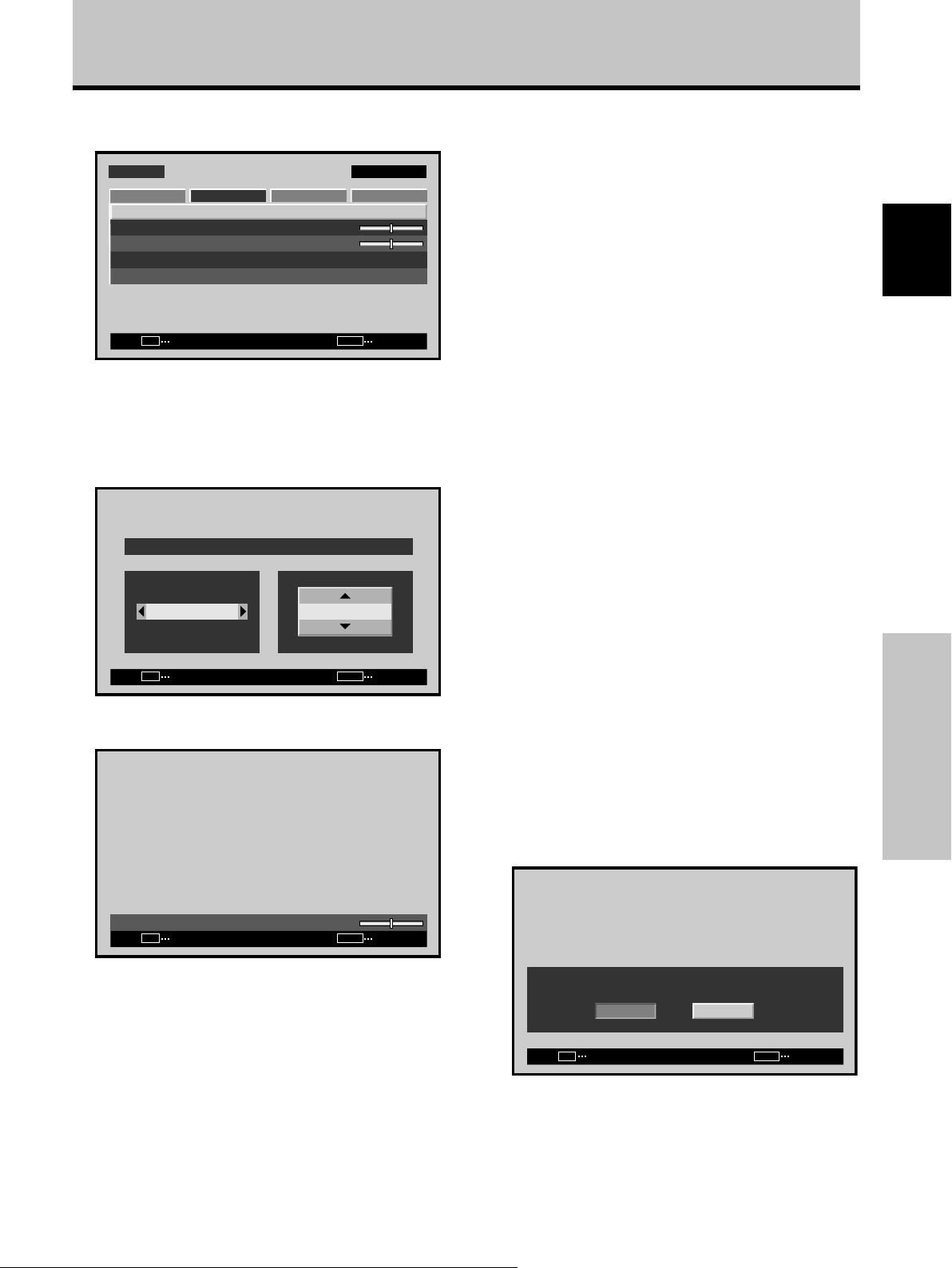
Réglages de l’IMAGE et de l’ÉCRAN
3 Utilisez les touches 5/∞ pour sélectionner le
paramètre à régler puis appuyez sur la touche SET.
MENU ENTRÉE1
POSITION
HORLOGE
PHASE
RÉINIT.ÉCRAN
SET MENU
ÉCRAN SETUP OPTIONIMAGE
ENTRÉE SORTIE
:
0/ 0
:
0
:
0
4 Utilisez les touches 2/3 et 5/∞ pour sélectionner
la valeur souhaitée.
÷ Lorsque la rubrique [POSITION] est sélectionnée,
les touches 2/3 contrôlent le mouvement dans le
sens horizontal (H) et les touches 5/∞ dans le sens
vertical (V).
POSITION
HV
+88+88
SET
VALIDER
÷ Utilisez les touches 2/3 pour le réglage des
paramètres [HORLOGE] et [PHASE].
MENU
SORTIE
Paramètres qui peuvent être réglés [ÉCRAN]
Voici de brèves explications sur les paramètres qui
peuvent être réglés grâce à l’option [ÉCRAN].
POSITION
H ······················· Réglage de la position latérale de
l’image.
V ························ Réglage de la position verticale de
l’image.
HORLOGE ········Réglage des signaux et du bruit. Ce
réglage agit sur la fréquence du signal
de l’horloge interne en fonction du
signal d’entrée vidéo.
PHASE ··············
Réglage du scintillement et des erreurs
de couleur. Ce réglage agit sur la phase
du signal de l’horloge interne dont la
fréquence a été réglée au moyen du
paramètre [HORLOGE].
Remarques
÷ Les paramètres de réglage [HORLOGE] et [PHASE] sont pris
en compte uniquement pour ENTRÉE1.
÷ Si la fréquence [HORLOGE] est changée, il se peut que
l’option [H] de la commande [POSITION] doive être retouchée.
÷ Si les paramètres de l’option [ÉCRAN] ont des valeurs
excessives, l’image peut être déformée.
÷ Lorsque [RÉGLAGE AUTO.] est réglé sur [ACTIF], la sélection
du mode de réglage [POSITION] ou [HORLOGE] fera s’afficher
un message sur l’écran, mais le réglage est possible.
Cependant, si la source est changée, la valeur mémorisée sera
celle qui a été définie automatiquement par le mode de
paramétrage automatique. Si vous désirez mémoriser une
valeur manuellement définie, réglez le mode [RÉGLAGE
AUTO.] sur [INACTIF] (pages 27 à 28) avant d’effectuer les
réglages.
Pour rétablir les valeurs par défaut des
paramètres de l’option [ÉCRAN]
Si les réglages effectués ne vous conviennent pas, il peut
être souhaitable de rétablir les valeurs par défaut des
différents paramètres de l’option [ÉCRAN] plutôt que de
continuer à modifier les réglages.
1 Au cours de l’opération 3 ci-dessus, utilisez les
touches 5/∞ pour sélectionner l’option [RÉINIT.
ÉCRAN] puis appuyez sur la touche SET.
Français
Réglages de l’IMAGE et de l’ÉCRAN
HORLOGE
SET
VALIDER
:
0
MENU
SORTIE
Remarque
Si ENTRÉE2 est sélectionné, seul le paramètre [POSITION] peut
être ajusté.
5 Appuyez sur la touche SET.
En appuyant sur la touche SET, vous mettez en
mémoire la valeur choisie et retournez à la page de
l’opération 3.
6
Appuyez sur la touche MENU pour abandonner la
page de menu lorsque la mise en oeuvre est terminée.
RÉINIT.ÉCRAN ?
OUI NON
SET MENU
VALIDER SORTIE
2 Utilisez les touches 2/3 pour choisir la valeur
[OUI] puis appuyez sur la touche SET.
Les valeurs par défaut des paramètres de l’option
[ÉCRAN] sont rétablies.
29
Fr
Page 90

Autres démarches
Réglage de l’orbiteur (ORBITER)
3
Utilisez les touches 5/∞ pour sélectionner
[PROTECT.ÉCRAN], puis appuyez sur la touche SET.
Cette fonction décale progressivement la position de
l’écran à intervalles réguliers.
÷ Cette fonction n’est pas prise en compte à l’emploi de
la fonction POINT ZOOM.
Français
Télécommande
STANDBY/ON MENU
DISPLAY
/ SET
SCREEN SIZE
MENU
2/3
5/∞
– VOL +INPUT
MENU ENTRÉE1
LANGUAGE
ÉCON.ÉNERGIE
TIMER
PROTECT.ÉCRAN
RÉGLAGE AUTO.
MODE AUTO
DÉTECTION PIP
GEL MULTI IMAGE
SET MENU
4
Utilisez les touches 5/∞ pour sélectionner [ORBITER].
ORBITER
FOCUS LEGER
SET
5 Appuyez sur
ÉCRAN SETUP OPTIONIMAGE
ENTRÉE SORTIE
ANTI MARQUAGE ÉCRAN
CHANGER
les touches 2/3
:FRANÇAIS
:STANDARD
:INACTIF
:ARRÊT
:ACTIF
:ARRÊT
:ARRÊT
:ARRÊT
MENU
SORTIE
pour valider le réglage.
Le réglage par défaut effectué en usine est [ARRÊT].
À chaque pression sur la touche, le réglage change
comme suit :
3 ARRÊT
3 MODE1
2/3MENU 5/∞
Panneau de commande de l’écran à plasma
1 Appuyez sur la touche MENU pour afficher la page
de menu.
Autres démarches
MENU ENTRÉE1
IMAGE
CONTRASTE
LUMINOSITÉ
AGRAND.HOR
AGRAND.VER
RÉINIT.IMAGE
SET
2
Utilisez les touches 2/3 pour sélectionner
ÉCRAN SETUP OPTION
:
:
:
:
ENTRÉE
[OPTION].
MENU ENTRÉE1
LANGUAGE
ÉCON.ÉNERGIE
TIMER
PROTECT.ÉCRAN
RÉGLAGE AUTO.
MODE AUTO
DÉTECTION PIP
ÉCRAN SETUP OPTIONIMAGE
:FRANÇAIS
:STANDARD
:INACTIF
:ARRÊT
:ACTIF
0
0
0
0
MENU
SORTIE
MODE3 2 MODE2 2
÷ ARRÊT ........... L’[ORBITER] n’est pas utilisé.
÷ MODE1 ......... La taille de l’image est réduite et la
position d’affichage sur l’écran est
changée.
÷ MODE2 ......... La taille de l’image est agrandie et la
position d’affichage sur l’écran est
changée.
÷ MODE3 ......... La position de l’écran est décalée en
fonction de l’orientation point-parpoint.
6
Lorsque les réglages sont terminés, appuyez sur la
touche MENU pour repasser à l’image d’écran normal.
Remarque
Le paramètre [ORBITER] affecte toutes les sources d’entrée.
30
Fr
Page 91

Réglage du FOCUS LEGER
Autres démarches
3
Utilisez les touches 5/∞ pour sélectionner
[PROTECT.ÉCRAN], puis appuyez sur la touche SET.
Les images sont adoucies par suppression du contraste
du bord.
MENU
2/3
5/∞
Télécommande
STANDBY/ON MENU
DISPLAY
/ SET
SCREEN SIZE
– VOL +INPUT
2/3MENU 5/∞
Panneau de commande de l’écran à plasma
1 Appuyez sur la touche MENU pour afficher la page
de menu.
MENU ENTRÉE1
IMAGE
CONTRASTE
LUMINOSITÉ
AGRAND.HOR
AGRAND.VER
RÉINIT.IMAGE
ÉCRAN SETUP OPTION
:
0
:
0
:
0
:
0
MENU ENTRÉE1
LANGUAGE
ÉCON.ÉNERGIE
TIMER
PROTECT.ÉCRAN
RÉGLAGE AUTO.
MODE AUTO
DÉTECTION PIP
GEL MULTI IMAGE
SET MENU
4
Utilisez les touches 5/∞ pour sélectionner [FOCUS
ÉCRAN SETUP OPTIONIMAGE
ENTRÉE SORTIE
:FRANÇAIS
:STANDARD
:INACTIF
:ARRÊT
:ACTIF
:ARRÊT
LEGER].
ANTI MARQUAGE ÉCRAN
ORBITER
FOCUS LEGER
SET MENU
5 Appuyez sur
CHANGER SORTIE
les touches 2/3
:ARRÊT
:ARRÊT
pour valider le réglage.
Le réglage par défaut effectué en usine est [ARRÊT].
À chaque pression sur la touche, le réglage change
comme suit :
3 ARRÊT
4 2
3 1
3 2 2 2
÷ ARRÊT ........... Le paramètre [FOCUS LEGER] est
annulé.
÷ 1 à 4 .............. Réglages pour [FOCUS LEGER].
L’adoucissement augmente dans
l’ordre croissant 1, 2, 3, 4.
Français
Autres démarches
SET
ENTRÉE
2
Utilisez les touches 2/3 pour sélectionner
[OPTION].
MENU ENTRÉE1
LANGUAGE
ÉCON.ÉNERGIE
TIMER
PROTECT.ÉCRAN
RÉGLAGE AUTO.
MODE AUTO
DÉTECTION PIP
GEL MULTI IMAGE
SET MENU
ÉCRAN SETUP OPTIONIMAGE
:FRANÇAIS
:STANDARD
:INACTIF
:ARRÊT
:ACTIF
:ARRÊT
ENTRÉE SORTIE
MENU
SORTIE
6
Lorsque les réglages sont terminés, appuyez sur la
touche MENU pour repasser à l’image d’écran normal.
Remarque
Le paramètre [FOCUS LEGER] affecte toutes les sources
d’entrée.
31
Fr
Page 92
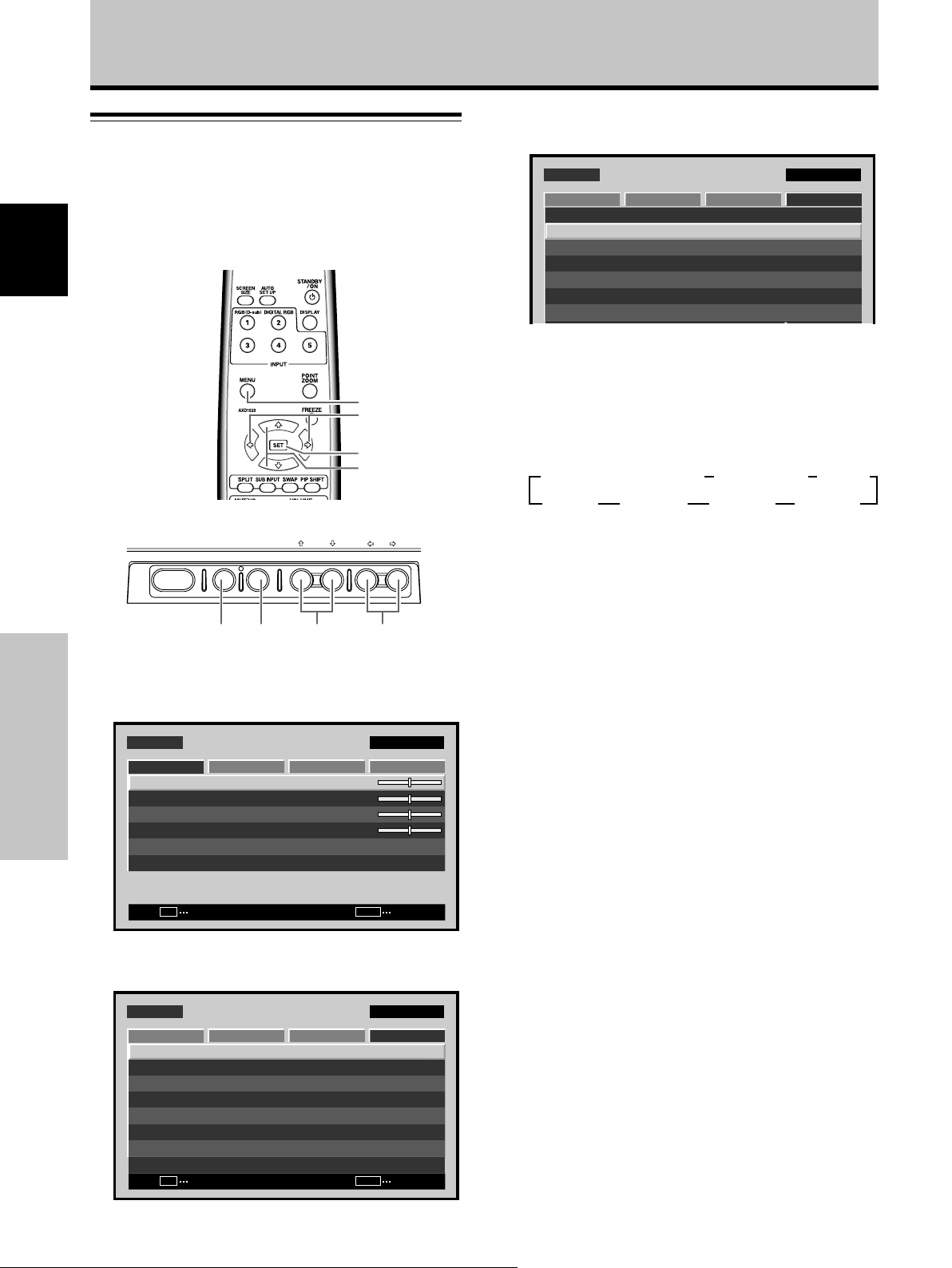
Autres démarches
Réglages d’économie d’énergie
3 Utilisez les touches 5/∞ pour sélectionner
[ÉCON.ÉNERGIE].
(ÉCON.ÉNERGIE)
Cette fonction permet une atténuation de la luminosité de
l’écran, un moyen de réduire la consommation de courant
et d’éviter la détérioration de l’écran.
Français
MENU
2/3
SET
5/∞
Télécommande
STANDBY/ON MENU
Panneau de commande de l’écran à plasma
1 Appuyez sur la touche MENU pour afficher la page
de menu.
MENU ENTRÉE1
IMAGE
Autres démarches
CONTRASTE
LUMINOSITÉ
AGRAND.HOR
AGRAND.VER
RÉINIT.IMAGE
SET
ENTRÉE
2 Utilisez les touches 2/3 pour sélectionner
[OPTION].
MENU ENTRÉE1
LANGUAGE
ÉCON.ÉNERGIE
TIMER
PROTECT.ÉCRAN
RÉGLAGE AUTO.
MODE AUTO
DÉTECTION PIP
GEL MULTI IMAGE
SET MENU
ENTRÉE SORTIE
DISPLAY
/ SET
ÉCRAN SETUP OPTION
ÉCRAN SETUP OPTIONIMAGE
:
:
:
:
MENU
:FRANÇAIS
:STANDARD
:INACTIF
:ARRÊT
:ACTIF
:ARRÊT
MENU ENTRÉE1
LANGUAGE
ÉCON.ÉNERGIE
TIMER
PROTECT.ÉCRAN
RÉGLAGE AUTO.
MODE AUTO
DÉTECTION PIP
ÉCRAN SETUP OPTIONIMAGE
:FRANÇAIS
:STANDARD
:INACTIF
:ARRÊT
:ACTIF
4 Appuyez sur la touche SET pour sélectionner
l’option [ÉCON.ÉNERGIE].
Le réglage par défaut effectué en usine est [STANDARD]
(PDP-607CMX/PDP-427CMX)/[STANDARD1] (PDP507CMX)
.
Le réglage change comme suit chaque fois que la
touche SET est actionnée:
3
3
STANDARD (STANDARD1
MUTE 2
– VOL +INPUT SCREEN SIZE
÷ STANDARD ...... Luminosité d’image normale (PDP-
MODE3 2 MODE2 2
607CMX/PDP-427CMX)
STANDARD2)
3 AUTO
MODE1 2
÷ STANDARD1, STANDARD2 .............
Luminosité d’image normale.
L’aspect peut être différent selon le type
d’image. (PDP-507CMX)
2/3MENU SET 5/∞
÷ AUTO ............... La luminosité se règle
automatiquement en fonction des
conditions de l’éclairage ambiant, de
manière à produire des images optimales.
(PDP-507CMX/PDP-427CMX)
÷ MODE1 ............ La luminosité est ajustée en
fonction du signal d’entrée, mais la
consommation de courant est inférieure à
0
0
0
0
÷ MODE2 ............ La luminosité est ajustée en
celle du mode [STANDARD] (STANDARD1,
STANDARD2).
fonction du signal d’entrée, mais la
consommation de courant est inférieure à
celle du mode [MODE1].
÷ MODE3 ............ La luminosité reste à un niveau
fixe, quel que soit le signal d’entrée, ce qui
SORTIE
contribue à réduire la détérioration de
l’écran par rémanence d’images virtuelles,
etc.
÷ MUTE* ............. A utiliser pour éteindre
temporairement l’image affichée.
* Pour rétablir l’image
÷ Appuyez sur une des touches MENU, DISPLAY, SUB INPUT,
SPLIT, SWAP ou PIP SHIFT.
÷ Commute le signal d’entrée.
÷ Place l’appareil en mode Attente.
5 Une fois terminés ces réglages, appuyez sur la
touche MENU pour repasser à l’écran normal.
Remarque
Le paramètre [ÉCON.ÉNERGIE] affecte toutes les sources
d’entrée.
32
Fr
Page 93

Commutation d’entrée automatique
Autres démarches
3 Utilisez les touches 5/∞ pour sélectionner [MODE
AUTO].
(MODE AUTO)
Cet écran possède un sélecteur [MODE AUTO] en option.
Lorsqu’il est validé, la source d’entrée de l’écran passe
automatiquement à INPUT1 lorsqu’un signal d’image est
détecté à la prise INPUT1.
MENU
2/3
SET
5/∞
Télécommande
STANDBY/ON MENU
Panneau de commande de l’écran à plasma
DISPLAY
/ SET
1 Appuyez sur la touche MENU pour afficher la page
de menu.
MENU ENTRÉE1
IMAGE
CONTRASTE
LUMINOSITÉ
AGRAND.HOR
AGRAND.VER
RÉINIT.IMAGE
SET
2
Utilisez les touches 2/3 pour sélectionner [OPTION].
MENU ENTRÉE1
LANGUAGE
ÉCON.ÉNERGIE
TIMER
PROTECT.ÉCRAN
RÉGLAGE AUTO.
MODE AUTO
DÉTECTION PIP
ÉCRAN SETUP OPTION
ENTRÉE
ÉCRAN SETUP OPTIONIMAGE
– VOL +INPUT SCREEN SIZE
2/3MENU SET 5/∞
:
0
:
0
:
0
:
0
MENU
SORTIE
:FRANÇAIS
:STANDARD
:INACTIF
:ARRÊT
:ACTIF
MENU ENTRÉE1
LANGUAGE
ÉCON.ÉNERGIE
TIMER
PROTECT.ÉCRAN
RÉGLAGE AUTO.
MODE AUTO
DÉTECTION PIP
GEL MULTI IMAGE
SET MENU
ÉCRAN SETUP OPTIONIMAGE
CHANGER SORTIE
:FRANÇAIS
:STANDARD
:INACTIF
:ARRÊT
:ACTIF
:ARRÊT
4 Appuyez sur la touche SET pour sélectionner
[ENTRÉE1].
Le réglage par défaut effectué en usine est [ARRÊT]
(hors service). A chaque pression sur la touche SET, la
fonction du sélecteur permute comme suit:
3 ARRÊT
ENTRÉE1 2
÷ ARRÊT ...... Le paramètre [MODE AUTO] est
désactivé.
÷
ENTRÉE1 ....
÷ Lorsqu’un signal est détecté à INPUT1,
la source d’entrée passe
automatiquement à [ENTRÉE1].
÷ Après que la fonction [MODE AUTO] a
provoqué le changement de l’entrée, la
source d’entrée repassera à celle qui
était sélectionnée avant l’action de la
fonction [MODE AUTO] si le signal
d’entrée n’est plus détecté.
÷ Si l’entrée change lorsque l’appareil est
en mode [MODE AUTO], une pression
sur la touche INPUT pour sélectionner
une entrée différente fera que le mode
[MODE AUTO] sera temporairement
désactivé, mais il pourra à nouveau
être activé en mettant l’appareil sous/
hors tension.
5 Une fois terminés ces réglages, appuyez sur la
touche MENU pour repasser à l’écran normal.
Remarques
÷ Le paramètre [MODE AUTO] pour [ENTRÉE1] est supporté
uniquement lorsqu’un signal RVB analogique SYNC séparé ou
SYNC composite est fourni. (Lorsqu’un signal G ON SYNC ou
un signal vidéo à composants est entré, la fonction [MODE
AUTO] est désactivée.)
÷ Le paramètre [MODE AUTO] affecte toutes les sources d’entrée.
Français
Autres démarches
33
Fr
Page 94

Autres démarches
Réglage de l’heure actuelle
3
Utilisez les touches 5/∞ pour sélectionner [TIMER],
puis appuyez sur la touche SET.
(HORLOGE)
Pour le réglage de l’heure actuelle, du jour de la semaine
et de l’heure d’été.
Français
Télécommande
STANDBY/ON MENU
DISPLAY
/ SET
MENU
2/3
SET
5/∞
– VOL +INPUT SCREEN SIZE
MENU ENTRÉE1
LANGUAGE
ÉCON.ÉNERGIE
TIMER
PROTECT.ÉCRAN
RÉGLAGE AUTO.
MODE AUTO
DÉTECTION PIP
GEL MULTI IMAGE
SET MENU
4
Utilisez les touches 5/∞ pour sélectionner
ÉCRAN SETUP OPTIONIMAGE
:FRANÇAIS
:STANDARD
:INACTIF
:ARRÊT
:ACTIF
:ARRÊT
ENTRÉE SORTIE
[HORLOGE], puis appuyez sur la touche SET.
TIMER
HORLOGE
PROG/REPETITION
RETOUR
SET
ENTRÉE
:ARRÊT
MENU
SORTIE
2/3MENU SET 5/∞
Panneau de commande de l’écran à plasma
1 Appuyez sur la touche MENU pour afficher la page
de menu.
MENU ENTRÉE1
IMAGE
Autres démarches
CONTRASTE
LUMINOSITÉ
AGRAND.HOR
AGRAND.VER
RÉINIT.IMAGE
2
Utilisez les touches 2/3 pour sélectionner
[OPTION].
MENU ENTRÉE1
LANGUAGE
ÉCON.ÉNERGIE
TIMER
PROTECT.ÉCRAN
RÉGLAGE AUTO.
MODE AUTO
DÉTECTION PIP
GEL MULTI IMAGE
SET
SET MENU
ÉCRAN SETUP OPTION
ENTRÉE
ÉCRAN SETUP OPTIONIMAGE
ENTRÉE SORTIE
:
0
:
0
:
0
:
0
MENU
:FRANÇAIS
:STANDARD
:INACTIF
:ARRÊT
:ACTIF
:ARRÊT
SORTIE
5 Utilisez les touches 2/3/5/∞ pour ajuster chaque
rubrique du menu.
HORLOGE
:ARRÊTHEURE D’ÉTÉ
LUNDI
REGLAGE
RETOUR
SET
CHANGER
12:00:00
MENU
SORTIE
÷ HEURE D’ÉTÉ ........... A utiliser pour ajuster l’heure
d’été.
MARCHE : L’heure actuelle plus 1 heure est affichée.
ARRÊT : Pour désactiver le mode [HEURE D’ÉTÉ].
÷ Semaine .................... Pour régler au jour actuel de
la semaine.
÷ Heure, Minute ........... Pour régler à l’heure et la
minute actuelles.
6 Quand les réglages sont terminés, utilisez les
touches 5/∞ pour sélectionner [RETOUR], puis
appuyez sur la touche SET pour revenir au menu
[TIMER].
Remarque
Le paramètre [TIMER] affecte toutes les sources d’entrée.
34
Fr
Page 95

Activation de la minuterie
Autres démarches
3
Utilisez les touches 5/∞ pour sélectionner [TIMER],
puis appuyez sur la touche SET.
L’horloge peut servir pour effectuer une programmation
préréglée.
MENU
2/3
SET
5/∞
Télécommande
STANDBY/ON MENU
DISPLAY
/ SET
– VOL +INPUT SCREEN SIZE
2/3MENU SET 5/∞
Panneau de commande de l’écran à plasma
1 Appuyez sur la touche MENU pour afficher la page
de menu.
MENU ENTRÉE1
IMAGE
CONTRASTE
LUMINOSITÉ
AGRAND.HOR
AGRAND.VER
RÉINIT.IMAGE
SET
2
Utilisez les touches 2/3 pour sélectionner
[OPTION].
MENU ENTRÉE1
LANGUAGE
ÉCON.ÉNERGIE
TIMER
PROTECT.ÉCRAN
RÉGLAGE AUTO.
MODE AUTO
DÉTECTION PIP
GEL MULTI IMAGE
SET MENU
ÉCRAN SETUP OPTION
ENTRÉE
ÉCRAN SETUP OPTIONIMAGE
ENTRÉE SORTIE
:
0
:
0
:
0
:
0
MENU
SORTIE
:FRANÇAIS
:STANDARD
:INACTIF
:ARRÊT
:ACTIF
:ARRÊT
MENU ENTRÉE1
LANGUAGE
ÉCON.ÉNERGIE
TIMER
PROTECT.ÉCRAN
RÉGLAGE AUTO.
MODE AUTO
DÉTECTION PIP
GEL MULTI IMAGE
SET MENU
4
Utilisez les touches 5/∞ pour sélectionner [PROG/
ÉCRAN SETUP OPTIONIMAGE
ENTRÉE SORTIE
:FRANÇAIS
:STANDARD
:INACTIF
:ARRÊT
:ACTIF
:ARRÊT
REPETITION].
TIMER
HORLOGE
/
REPETITION
PROG
RETOUR
SET MENU
5 Appuyez sur
CHANGER SORTIE
les touches 2/3
:ARRÊT
pour valider le réglage.
Le réglage par défaut effectué en usine est [ARRÊT].
À chaque pression sur la touche, le réglage change
comme suit :
3 ARRÊT
REPET. 2 PROG. 2
6
Quand les réglages sont terminés, utilisez les
touches 5/∞ pour sélectionner [RETOUR], puis
appuyez sur la touche SET pour revenir à l’image
de l’écran normal.
Réglage [PROG.]
÷ Chaque jour, l’alimentation est fournie à 10h00.
Les réglages d’entrée et de fonction sont les mêmes
que ceux définis la dernière fois que l’appareil a été mis
hors tension (OFF).
÷ A 20h00 (8 heures du soir), l’écran devient blanc.
A 21h00 (9 heures du soir), l’alimentation est coupée
(OFF).
Réglage [REPET.]
÷ Les écrans pour les entrées INPUT1 et INPUT2 sont
affichés alternativement chacun pendant 10 minutes.
Français
Autres démarches
35
Fr
Page 96
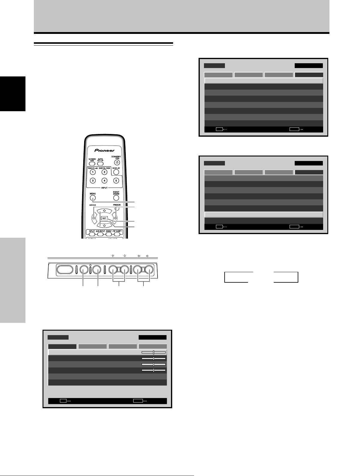
Autres démarches
Réglage du mode de sous-écran
2
Utilisez les touches 2/3 pour sélectionner
[OPTION].
(DÉTECTION PIP)
Pendant l’affichage Image dans image (PIP), si aucun signal
d’entrée de sous-écran n’est détecté, les bords noirs du
sous-écran sont automatiquement éliminés.
Français
La fonction du mode sous-écran est désactivée pendant
l’affichage Côte à côte.
÷ L’absence de signal d’entrée de sous-écran signifie qu’il
n’y a pas de signal vidéo ou de signal de
synchronisation.
MENU
2/3
SET
5/∞
MENU ENTRÉE1
LANGUAGE
ÉCON.ÉNERGIE
TIMER
PROTECT.ÉCRAN
RÉGLAGE AUTO.
MODE AUTO
DÉTECTION PIP
GEL MULTI IMAGE
SET MENU
3
Utilisez les touches 5/∞ pour sélectionner
ÉCRAN SETUP OPTIONIMAGE
:FRANÇAIS
:STANDARD
:INACTIF
:ARRÊT
:ACTIF
:ARRÊT
ENTRÉE SORTIE
[DÉTECTION PIP].
MENU ENTRÉE1
LANGUAGE
ÉCON.ÉNERGIE
TIMER
PROTECT.ÉCRAN
RÉGLAGE AUTO.
MODE AUTO
DÉTECTION PIP
GEL MULTI IMAGE
SET MENU
ÉCRAN SETUP OPTIONIMAGE
:FRANÇAIS
:STANDARD
:INACTIF
:ARRÊT
:ACTIF
:ARRÊT
CHANGER SORTIE
Télécommande
STANDBY/ON MENU
DISPLAY
/ SET
– VOL +INPUT SCREEN SIZE
2/3MENU SET 5/∞
Autres démarches
Panneau de commande de l’écran à plasma
1 Appuyez sur la touche MENU pour afficher la page
de menu.
MENU ENTRÉE1
IMAGE
CONTRASTE
LUMINOSITÉ
AGRAND.HOR
AGRAND.VER
RÉINIT.IMAGE
SET
ÉCRAN SETUP OPTION
:
:
:
:
ENTRÉE
0
0
0
0
MENU
SORTIE
4 Appuyez sur la touche SET pour valider le réglage.
Le réglage par défaut effectué en usine est [ACTIF].
À chaque pression sur la touche, le réglage change
comme suit :
3 ACTIF
INACTIF 2
÷ ACTIF ............. Si aucun signal d’entrée de sous-
écran n’est détecté pendant
l’affichage de sous-écran, le bord
noir du sous-écran disparaîtra après
3 secondes.
÷ INACTIF .......... Les sous-écrans sans entrée
resteront et leur bord noir sera
visible.
5
Lorsque les réglages sont terminés, appuyez sur la
touche MENU pour repasser à l’image d’écran normal.
Remarque
Le paramètre [DÉTECTION PIP] affecte toutes les sources
d’entrée.
36
Fr
Page 97

Réglage de l’écran de mémo
Autres démarches
3
Utilisez les touches 5/∞ pour sélectionner [GEL
MULTI IMAGE].
(GEL MULTI IMAGE)
Lors d’un réglage à une position autre que [ARRÊT], l’image
affichée lorsque la touche FREEZE est actionnée sera
affichée dans un sous-écran comme une image « gelée ».
MENU
2/3
FREEZE
SET
5/∞
Télécommande
STANDBY/ON MENU
DISPLAY
/ SET
Panneau de commande de l’écran à plasma
1 Appuyez sur la touche MENU pour afficher la page
de menu.
MENU ENTRÉE1
IMAGE
CONTRASTE
LUMINOSITÉ
AGRAND.HOR
AGRAND.VER
RÉINIT.IMAGE
SET
2
Utilisez les touches 2/3 pour sélectionner
[OPTION].
ÉCRAN SETUP OPTION
ENTRÉE
– VOL +INPUT SCREEN SIZE
2/3MENU SET 5/∞
:
0
:
0
:
0
:
0
MENU
SORTIE
MENU ENTRÉE1
LANGUAGE
ÉCON.ÉNERGIE
TIMER
PROTECT.ÉCRAN
RÉGLAGE AUTO.
MODE AUTO
DÉTECTION PIP
GEL MULTI IMAGE
SET MENU
ÉCRAN SETUP OPTIONIMAGE
:FRANÇAIS
:STANDARD
:INACTIF
:ARRÊT
:ACTIF
:ARRÊT
CHANGER SORTIE
4 Appuyez sur la touche SET pour valider le réglage.
Le réglage par défaut effectué en usine est [ARRÊT].
À chaque pression sur la touche, le réglage change
comme suit :
3 ARRÊT 3 S BY S 3 PIP
÷ ARRÊT ............ L’image fixe affichée au moment où
la touche FREEZE a été actionné est
affichée comme image simple sur la
totalité de l’écran.
÷ S BY S ............ Quand la touche FREEZE est
actionnée, une image gelée est
affichée sur le sous-écran Côte à
côte.
÷ PIP .................. Quand la touche FREEZE est
actionnée, une image gelée est
affichée sur le sous-écran Image
dans image (du bas à gauche au
haut à gauche).
5
Lorsque les réglages sont terminés, appuyez sur la
touche MENU pour repasser à l’image d’écran normal.
Remarques
Cette fonction est tributaire des conditions suivantes :
÷ Elle n’agit pas sur un affichage multi-écran.
÷ Elle est désactivée si la touche FREEZE est appuyée à
nouveau alors que la fonction est en service.
÷ Elle sera désactivée en cas de réglage à l’affichage multi-écran
pendant que la fonction est en service.
÷ Le paramètre [GEL MULTI IMAGE] affecte toutes les sources
d’entrée.
Français
Autres démarches
MENU ENTRÉE1
LANGUAGE
ÉCON.ÉNERGIE
TIMER
PROTECT.ÉCRAN
RÉGLAGE AUTO.
MODE AUTO
DÉTECTION PIP
GEL MULTI IMAGE
SET MENU
ÉCRAN SETUP OPTIONIMAGE
:FRANÇAIS
:STANDARD
:INACTIF
:ARRÊT
:ACTIF
:ARRÊT
ENTRÉE SORTIE
37
Fr
Page 98

Informations complémentaires
Nettoyage
Le nettoyage régulier de l’écran à plasma prolonge sa
durée de vie et permet de maintenir ses performances.
La manière de nettoyer l’écran est indiquée ci-après.
Avant tout nettoyage, débranchez la fiche du cordon
Français
d’alimentation.
Nettoyage du panneau de l’écran et du boîtier
de télécommande
N’utilisez aucun produit volatil tel que les essences ou les
diluants pour peinture, qui peuvent endommager la
finition de l’écran ou du boîtier de télécommande.
Nettoyez l’écran à plasma au moyen d’un chiffon sec et
doux. Dans le cas des taches tenaces, vous pouvez
utilisez un chiffon humecté d’une solution étendue de
détergent. Essorez soigneusement le chiffon avant de
frotter les taches. Essuyez ensuite la surface avec un
chiffon sec.
Nettoyage des ouïes d’aération
En règle générale, utilisez un aspirateur une fois par mois
pour nettoyer les ouïes, à l’arrière de l’écran à plasma (si
cela est possible, réglez au minimum la puissance de
l’aspirateur).
Pour éviter toute anomalie de fonctionnement, une
surchauffe de l’écran à plasma et un incendie, veillez à ce
que les ouïes d’aération ne soient pas obstruées.
PDP-607CMX
Ouïes
Ouïes
Nettoyage de la surface de l’écran
Après avoir épousseté l’écran, frottez-le délicatement avec
le chiffon de nettoyage fourni ou un autre linge doux (coton,
flanelle, etc.). N’utilisez pas de mouchoir en papier ni de
chiffon rugueux. La surface de l’écran peut facilement être
rayée; ne frottez aucun objet dur sur cette surface.
Si vous nettoyez la surface de l’écran avec un linge
humide, des goutelettes d’eau de la surface risquent
d’entrer à l’intérieur et de provoquer une défaillance.
Informations complémentaires
PDP-507CMX
Ouïes
PDP-427CMX
Ouïes
Ouïes Ouïes
Ouïes
Ouïes Ouïes
Ouïes
38
Fr
Ouïes Ouïes
Page 99

Informations complémentaires
Guide de dépannage
Une erreur de commande peut parfois être interprétée
comme une anomalie de fonctionnement.
Si une indication est affichée sur l’écran, consultez le
tableau ci-dessous. Dans le cas contraire, et si vous
pensez que cet appareil est défectueux, procédez aux
vérifications de la page 40. Il peut arriver aussi que le
défaut provienne d’un autre élément de l’installation;
assurez-vous que ce n’est pas le cas. Si, en dépit de ces
contrôles, vous n’êtes pas en mesure d’obtenir un
fonctionnement satisfaisant, consultez le revendeur.
Mode d’autodiagnostic
Des messages peuvent apparaître à la partie inférieure de
l’écran pour signaler les conditions de fonctionnement ou
une anomalie dans les raccordements. Après vérification
du message, examinez les conditions de l’écran.
MESSAGE D’ERREUR
ATTENTION
FREQ. HORS STANDARD
ou
ATTENTION
SIGNAL NON RECONNU
ou
SIGNAL INCORRECT
DANGER
ALERTE TEMPÉRATURE
COUPURE ALIM.
DANGER
DÉFAUT VENTILATION
COUPURE ALIM.
ERREUR
OPÉRATION INVALIDE
COUPURE ALIM.
CORRECTION
¶ Le signal d’entrée actuel
n’est pas accepté par
l’appareil. Vérifiez le
Tableau des compatibilités
de signal d’ordinateur aux
pages 43 à 48 et réglez en
conséquence le signal de
sortie de l’ordinateur.
¶ Mettez l’écran hors tension
(pages 9 à 11).
¶ La température ambiante
dépasse-t-elle 40 °C ?
¶
Enlevez tout objet obstruant
les ouïes d’aération sur
l’écran à plasma.
¶ Le ventilateur de
refroidissement fonctionne
mal. Mettez
immédiatement l’écran
hors tension, retirez la fiche
d’alimentation hors de la
prise secteur et consultez
un centre de service ou un
concessionnaire Pioneer.
¶ Une opération invalide a
été tentée. Vérifiez les
signaux d’entrée, les
raccordements et les
autres réglages.
¶ Coupez l’alimentation
principale, attendez 1 à 2
minutes et remettez
l’appareil sous tension. Si la
difficulté subsiste, retirez la
fiche d’alimentation hors
de la prise secteur et
consultez un centre de
service ou un
concessionnaire Pioneer.
Français
Informations complémentaires
39
Fr
Page 100

Informations complémentaires
Anomalies générales
Anomalies Remèdes possibles
• Absence d’alimentation.
•L’écran à plasma ne
fonctionne pas.
Français
• La télécommande ne
fonctionne pas.
•L’image est tronquée.
• Les couleurs sont
anormales, délavées, trop
sombres, mal repérées.
•L’alimentation se coupe
soudainement.
• Absence d’image.
• La fiche du cordon d’alimentation est-elle branchée sur une prise secteur? (page 16)
•L’écran à plasma est-il sous tension grâce à l’interrupteur MAIN POWER? (pages 9 à 11)
• Des sources d’influence extérieures telles que l’éclairage, l’électricité statique, etc. peuvent
provoquer une anomalie de fonctionnement. Si toutefois c’est le cas, mettez l’appareil en marche
en commutant d’abord l’interrupteur d’alimentation général MAIN POWER sur arrêt ou marche
puis débranchez le cordon d’alimentation et rebranchez-le 1 à 2 minutes plus tard.
• Les piles sont-elles correctement placées (polarités +, –)? (page 8)
• Les piles sont-elles usagées? (Remplacez les piles.)
• Un objet fait-il obstacle au capteur du signal de télécommande? (page 8)
• Dirigez la télécommande vers le capteur du signal de télécommande lors de son utilisation (page 8).
• Le format d’image choisi est-il convenable?
Choisissez une autre format d’image (page 22).
• Les valeurs choisies pour [ÉCRAN], par exemple le format de l’image, sont-elles correctes?
(pages 22 à 23 et 28 à 29)
• La fonction POINT ZOOM est-elle en service? (page 23)
• Réglez la tonalité des couleurs (page 26).
• La pièce est-elle trop éclairée?
L’image peut paraître sombre si la pièce est trop éclairée.
• La température intérieure de l’écran à plasma a augmenté. (Les ouïes d’aération sont obstruées.)
Dégagez les ouïes d’aération et nettoyez-les (page 38).
• La fonction [GESTION D'ALIM.] est-elle en service (réglée sur [MARCHE])? (page 25)
• Les raccordements aux autres appareils sont-ils corrects? (pages 14 à 15)
• La mise en oeuvre a-t-elle été réalisée correctement après les raccordements? (pages 18 à 19)
•L’entrée choisie est-elle correcte? (page 20)
• Le signal d’entrée est-il compatible? (pages 43 à 48)
• Les réglages [IMAGE] sont-ils corrects? (page 26)
Anomalies qui n’en sont pas
Anomalies Remèdes possibles
•L’image a un format réduit.
• Les caractères affichés sont
déformés.
• Un son aigu est parfois émis
par l’écran à plasma.
• Les portions lumineuses de
l’image semblent manquer
d’intensité.
Informations complémentaires
• Les taches ou du bruit se
forment sur l’écran.
• Des rayures se forment sur
l’écran.
•L’écran à plasma émet des
bruits.
• Changement de vitesse du
ventilateur.
• Le témoin ON (vert) ne
s’allume pas.
• Le format d’image choisi est-il correct? (pages 22 à 23 et 28 à 29)
• Utilisez l’option [ÉCRAN] pour effectuer le réglage (pages 28 à 29).
Si vous ne constatez aucune amélioration, l’écran à plasma peut limiter la zone d’affichage.
Vérifiez le compatibilités de signal d’ordinateur (pages 43 à 48).
•L’expansion et la contraction causés par la température ambiante peuvent provoquer l’émission
de bruits. Cela ne traduit pas une anomalie.
• Si le niveau du signal d’entrée vidéo est trop élevé, les zones brillantes semblent perdre de leur
intensité.
Augmentez le niveau du contraste et vérifiez les réglages de l’image (page 26).
• Cela peut provenir des brouillages dus à un moteur d’appareil domestique tel qu’un sèchecheveux, un aspirateur, une perceuse, ou encore du démarreur d’une voiture ou d’une moto, etc.,
ou d’un thermostat, etc. ou d’une enseigne lumineuse, ou d’une ligne électrique, etc.
• Cela peut provenir des ondes radio émises par une station de télévision, une station FM, un radioamateur, une radio publique (radio simple), etc., ou encore d’un ordinateur, d’un téléviseur, d’un
appareil audio, d’un appareil vidéo.
• Un fort champ électromagnétique peut provoquer une déformation de l’image ou une anomalie
similaire.
• Bruit normal du ventilateur et des composants coulissants internes de l’écran à plasma. Il ne
s’agit pas d’une anomalie.
• La vitesse du ventilateur change automatiquement en fonction des conditions ambiantes. Il ne
s’agit pas d’une anomalie.
• Il se peut qu’en fonction des réglages effectués par l’installateur, le témoin ON ne s’allume pas
dans certains cas. Consultez le technicien chargé de l’installation.
40
Fr
 Loading...