


GM-7100ES
Pioneer GM-7100ES, GM-7100XU, GM-7100CN, GM-7150M, GM-7150XU Service Manual
...
PIONEER CORPORATION 4-1, Meguro 1-Chome, Meguro-ku, Tokyo 153-8654, Japan
PIONEER ELECTRONICS (USA) INC. P.O.Box 1760, Long Beach, CA 90801-1760 U.S.A.
PIONEER EUROPE NV Haven 1087 Keetberglaan 1, 9120 Melsele, Belgium
PIONEER ELECTRONICS ASIACENTRE PTE.LTD. 253 Alexandra Road, #04-01, Singapore 159936
C PIONEER CORPORATION 2004
K-ZZB. DEC. 2004 Printed in Japan
ORDER NO.
CRT3371
MONO POWER AMPLIFIER
GM-7100M/XU/EW
GM-7100M/XU/EW
For details, refer to "Important check points for good servicing".
GM-7100M
/XU/UC
GM-7100M/XU/ES
GM-7100M/XU/CN
GM-7150M
/XU/UC
7
Q
Q
TEL 13942296513 QQ 376315150 892498299
3
6
3
1
5
1
5
0
8
9
2
4
9
2
8
9
9
TEL 13942296513 QQ 376315150 892498299
TEL
13942296513
Q
Q
3
7
6
3
1
5
1
5
0
8
9
2
4
9
8
2
9
9
w
w
w
.
xia
o
y
u
1
6
3
.
c
o
m
2
1
234
12
34
F
E
D
C
B
A
GM-7100M/XU/EW
SAFETY INFORMATION
CAUTION
This service manual is intended for qualified service technicians; it is not meant for the casual do-it-yourselfer.
Qualified technicians have the necessary test equipment and tools, and have been trained to properly and safely repair
complex products such as those covered by this manual.
Improperly performed repairs can adversely affect the safety and reliability of the product and may void the warranty.
If you are not qualified to perform the repair of this product properly and safely, you should not risk trying to do so
and refer the repair to a qualified service technician.
W
ARNING
This product contains lead in solder and certain electrical parts contain chemicals which are known to the state of
California to cause cancer, birth defects or other reproductive harm.
Health & Safety Code Section 25249.6 - Proposition 65
- Service Precaution
You should conform to the regulations governing the product (safety, radio and noise, and other regulations),
and should keep the safety during servicing by following the safety instructions described in this manual.
Q
Q
TEL 13942296513 QQ 376315150 892498299
3
7
6
3
1
5
1
5
0
8
9
2
4
9
8
2
9
9
TEL 13942296513 QQ 376315150 892498299
TEL
13942296513
Q
Q
3
7
6
3
1
5
1
5
0
8
9
2
4
9
8
2
9
9
w
w
w
.
xia
o
y
u
1
6
3
.
c
o
m
3
5
6
7
8
F
E
D
C
B
A
5
6
7
8
GM-7100M/XU/EW
[Important Check Points for Good Servicing]
In this manual, procedures that must be performed during repairs are marked with the below symbol.
Please be sure to confirm and follow these procedures.
1. Product safety
Please conform to product regulations (such as safety and radiation regulations), and maintain a safe servicing environment by
following the safety instructions described in this manual.
1 Use specified parts for repair.
Use genuine parts. Be sure to use important parts for safety.
2 Do not perform modifications without proper instructions.
Please follow the specified safety methods when modification(addition/change of parts) is required due to interferences such as
radio/TV interference and foreign noise.
3 Make sure the soldering of repaired locations is properly performed.
When you solder while repairing, please be sure that there are no cold solder and other debris.
Soldering should be finished with the proper quantity. (Refer to the example)
4 Make sure the screws are tightly fastened.
Please be sure that all screws are fastened, and that there are no loose screws.
5 Make sure each connectors are correctly inserted.
Please be sure that all connectors are inserted, and that there are no imperfect insertion.
6 Make sure the wiring cables are set to their original state.
Please replace the wiring and cables to the original state after repairs.
In addition, be sure that there are no pinched wires, etc.
7 Make sure screws and soldering scraps do not remain inside the product.
Please check that neither solder debris nor screws remain inside the product.
8 There should be no semi-broken wires, scratches, melting, etc. on the coating of the power cord.
Damaged power cords may lead to fire accidents, so please be sure that there are no damages.
If you find a damaged power cord, please exchange it with a suitable one.
9 There should be no spark traces or similar marks on the power plug.
When spark traces or similar marks are found on the power supply plug, please check the connection and advise on secure
connections and suitable usage. Please exchange the power cord if necessary.
0 Safe environment should be secured during servicing.
When you perform repairs, please pay attention to static electricity, furniture, household articles, etc. in order to prevent injuries.
Please pay attention to your surroundings and repair safely.
2. Adjustments
To keep the original performance of the products, optimum adjustments and confirmation of characteristics within specification.
Adjustments should be performed in accordance with the procedures/instructions described in this manual.
4. Cleaning
For parts that require cleaning, such as optical pickups, tape deck heads, lenses and mirrors used in projection monitors, proper
cleaning should be performed to restore their performances.
3. Lubricants, Glues, and Replacement parts
Use grease and adhesives that are equal to the specified substance.
Make sure the proper amount is applied.
5. Shipping mode and Shipping screws
To protect products from damages or failures during transit, the shipping mode should be set or the shipping screws should be
installed before shipment. Please be sure to follow this method especially if it is specified in this manual.
7
Q
Q
TEL 13942296513 QQ 376315150 892498299
TEL
3
13942296513
6
3
1
5
1
5
0
Q
Q
3
7
6
8
3
9
1
5
1
2
5
4
0
9
8
9
8
2
4
2
9
8
9
2
9
9
9
TEL 13942296513 QQ 376315150 892498299
w
w
w
.
xia
o
y
u
1
6
3
.
c
o
m

4
1
234
12
34
F
E
D
C
B
A
GM-7100M/XU/EW
CONTENTS
SAFETY INFORMATION............................................2
1. SPECIFICATIONS .......................................................5
2. EXPLODED VIEWS AND PARTS LIST ......................6
2.1 PACKING..............................................................6
2.2 EXTERIOR............................................................8
3. SCHEMATIC DIAGRAM...........................................12
3.1 OVERALL CONNECTION DIAGRAM(GUIDE PAGE)
....12
3.2 REMOTE CONTROL UNIT ................................18
4. PCB CONNECTION DIAGRAM................................20
4.1 AMP UNIT..........................................................20
4.2 REMOTE CONTROL UNIT ................................24
5. ELECTRICAL PARTS LIST........................................25
6. ADJUSTMENT.........................................................28
7. GENERAL INFORMATION.......................................29
7.1 DIAGNOSIS .......................................................29
7.1.1 DISASSEMBLY.........................................29
7.1.2
CONNECTOR FUNCTION DESCRIPTION
......31
8. OPERATIONS ...........................................................32
Q
Q
TEL 13942296513 QQ 376315150 892498299
3
7
6
3
1
5
1
5
0
4
2
9
8
9
8
2
9
9
TEL 13942296513 QQ 376315150 892498299
TEL
13942296513
Q
Q
3
7
6
3
1
5
1
5
0
8
9
2
4
9
8
2
9
9
w
w
w
.
xia
o
y
u
1
6
3
.
c
o
m

5
5
6
7
8
F
E
D
C
B
A
5
6
7
8
GM-7100M/XU/EW
1. SPECIFICATIONS
Power source .......................................................................................................... 14.4 V DC (10.8 — 15.1 V allowable)
Grounding system .......................................................................................................................................... Negative type
Current consumption .................................................................................................... 33.0 A (at continuous power, 4 Ω)
Backup current.................................................................................................................................................. 3 mA or less
Average current drawn* .......................................................................................................... 9.0 A (4 Ωfor one channel)
16.0 A (2 Ω for one channel)
Fuse ........................................................................................................................................................................ 30 A ×2
Dimensions ...................................................................................................................... 300 (W) × 60 (H) × 327 (D) mm
Weight .................................................................................................................... 4.7 kg (Leads for wiring not included)
Maximum power output .............................................................................................. 500 W × 1 (4 Ω) / 800 W × 1 (2 Ω)
Continuous power output .............................................................. 250 W × 1 (at 14.4 V, 4 Ω, 20 — 240 Hz 0.5% THD)
360 W × 1 (at 14.4 V, 2 Ω, 20 — 240 Hz 0.8% THD)
Continuous power output (DIN power) .......................................................... 380 W × 1 (4 Ω) (DIN45324, +B=14.4 V)
Load impedance .......................................................................................................................... 4 Ω (2 — 8 Ω allowable)
Frequency response .............................................................................................................. 10 — 240 Hz (+0 dB, –3 dB)
Signal-to-noise ratio .................................................................................................................... 100 dB (IEC-A network)
Distortion ........................................................................................................................................ 0.03 % (10 W, 120 Hz)
Low pass filter .................................................................................................................. Cut off frequency: 40 — 240 Hz
Cut off slope: –12 dB/oct
Bass Boost .............................................................................................................................................. Frequency: 50 Hz
Level: 0/6/9/12 dB
Gain control .................................................................................................................................. RCA: 200 mV — 6.5 V
Speaker: 0.8 — 26 V
Maximum input level / impedance ...................................................................................................... RCA: 6.5 V / 22 kΩ
Speaker: 26 V / 40 kΩ
Note:
• Specifications and the design are subject to possible modification without notice due to improvements.
*Average current drawn
• The average current drawn is nearly the maximum current drawn by this unit when an audio signal is input. Use this value when
working out total current drawn by multiple power amplifiers.
Q
TEL 13942296513 QQ 376315150 892498299
Q
TEL
7
3
13942296513
6
3
1
5
1
5
0
7
3
Q
Q
2
9
8
5
1
5
1
3
6
4
0
9
8
9
8
2
4
2
9
8
9
2
9
9
9
TEL 13942296513 QQ 376315150 892498299
w
w
w
.
xia
o
y
u
1
6
3
.
c
o
m
6
1
234
12
34
F
E
D
C
B
A
GM-7100M/XU/EW
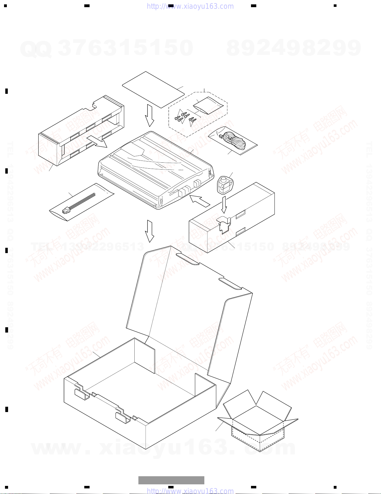
2. EXPLODED VIEWS AND PARTS LIST
2.1 PACKING
7
5
6
3
11
12
8
8
9
10
1
5
4
2
Q
Q
3
7
6
3
1
5
1
5
0
8
9
2
4
9
8
2
9
9
TEL 13942296513 QQ 376315150 892498299
TEL
13942296513
3
Q
Q
7
6
3
1
5
1
5
0
8
9
2
4
9
8
2
9
TEL 13942296513 QQ 376315150 892498299
9
w
w
w
.
xia
o
y
u
1
6
3
.
c
o
m
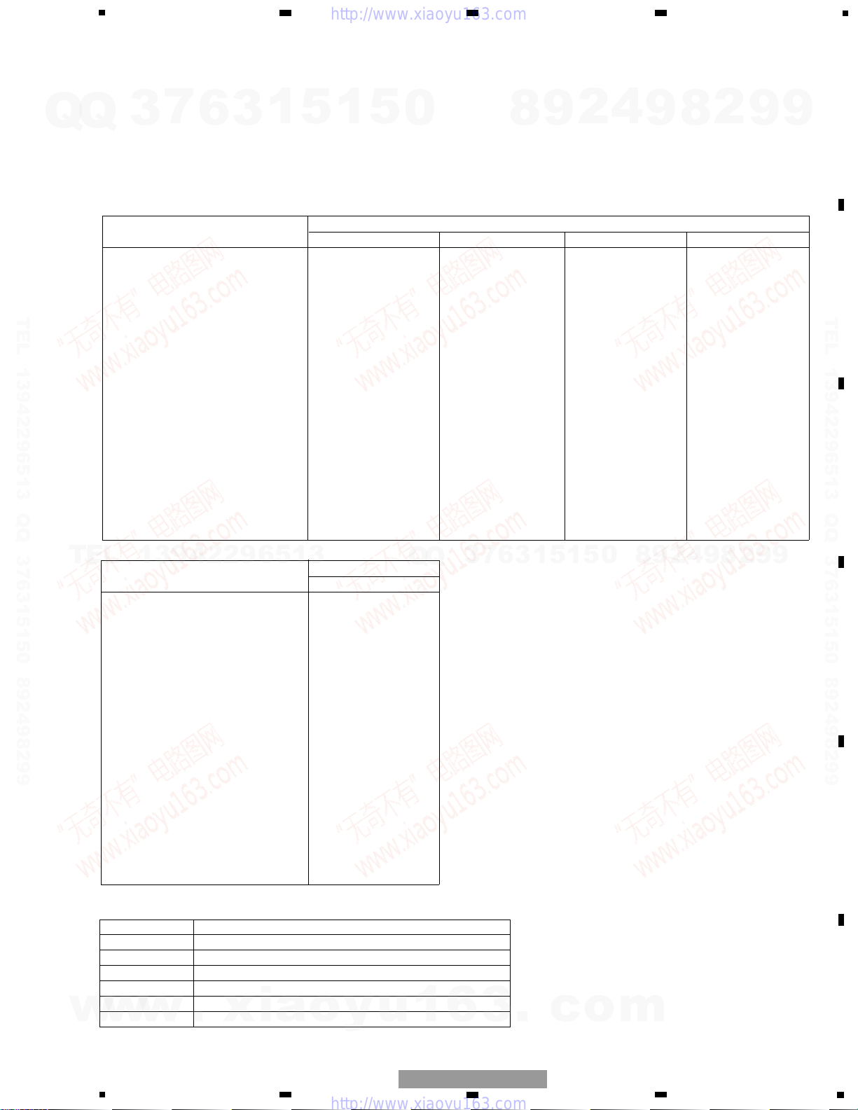
Part No.
Mark No. Description GM-7150M/XU/UC
1 Cord Assy CDE7736
2 Cord Assy CDE7804
3 Screw Assy CEA4836
4 Screw BYC30P100FZK
5 Screw BYC40P180FZK
* 6 Polyethylene Sheet CNM4338
7 Polyethylene Bag CEG1351
8 Protector CHP2911
9 Carton CHG5367
10 Contain Box CHL5367
11-1 Polyethylene Bag CEG1116
11-2 Owner’s Manual CRD3921
* 11-3 Warranty Card CRY1070
* 11-4 Card Not used
11-5 Owner’s Manual Not used
12 Remote Control Assy CXC4064
Part No.
Mark No. Description GM-7100M/XU/EW GM-7100M/XU/UC GM-7100M/XU/ES GM-7100M/XU/CN
1 Cord Assy CDE7736 CDE7736 CDE7736 CDE7736
2 Cord Assy CDE7804 Not used Not used Not used
3 Screw Assy CEA4836 CEA4835 CEA4835 CEA4835
4 Screw BYC30P100FZK Not used Not used Not used
5 Screw BYC40P180FZK BYC40P180FZK BYC40P180FZK BYC40P180FZK
* 6 Polyethylene Sheet CNM4338 CNM4338 CNM4338 CNM4338
7 Polyethylene Bag CEG1317 CEG1351 CEG1317 CEG1317
8 Protector CHP2911 CHP2911 CHP2911 CHP2911
9 Carton CHG5364 CHG5366 CHG5365 CHG5466
10 Contain Box CHL5364 CHL5366 CHL5365 CHL5466
11-1 Polyethylene Bag CEG1116 CEG1116 CEG1116 CEG1116
11-2 Owner’s Manual CRD3920 CRD3922 CRD3923 CRB2042
* 11-3 Warranty Card CRY1157 Not used Not used ARY7046
* 11-4 Card Not used ARY1048 Not used Not used
11-5 Owner’s Manual Not used Not used CRD3924 Not used
12 Remote Control Assy CXC4064 Not used Not used Not used
7
5
6
7
8
F
E
D
C
B
A
5
6
7
8
GM-7100M/XU/EW
- PACKING SECTION PARTS LIST
NOTE:
- Parts marked by “*” are generally unavailable because they are not in our Master Spare Parts List.
- The > mark found on some component parts indicates the importance of the safety factor of the part.
Therefore, when replacing, be sure to use parts of identical designation.
- Screws adjacent to ∇ mark on the product are used for disassembly.
- For the applying amount of lubricants or glue, follow the instructions in this manual.
( In the case of no amount instructions, apply as you think it appropriate.)
- Owner's Manual
Part No. Language
CRD3920 English, Spanish, German, French, Italian, Dutch
CRD3921 English, French, Spanish
CRD3922 English, French, Spanish
CRD3923 English, Spanish
CRD3924 Arabic, Portuguese(B)
CRB2042 Traditional Chinese
1
5
0
Q
Q
TEL 13942296513 QQ 376315150 892498299
7
3
6
3
1
5
8
9
2
4
9
8
2
9
9
TEL 13942296513 QQ 376315150 892498299
TEL
13942296513
Q
Q
3
7
6
3
1
5
1
5
0
8
9
2
4
9
8
2
9
9
w
w
w
.
xia
o
y
u
1
6
3
.
c
o
m

7
7
2
2
2
2
3
3
3
3
3
33
15
15
15
22
22
40
29
36
34
34
33
33
17
18
15
15
15
15
15
33
32
20
23
34
31
30
33
19
16
21
35
34
14
28
26
25
24
33
14
27
2
2
2
5
2
2
3
48
41
42
43
45
46
44
47
4
4
4
1
1
1
5
5
5
5
1
1
1
8
9
39
39
12
10
12
12
13
4
4
38
38
6
11
37
A
49
B
8
1
234
12
34
F
E
D
C
B
A
GM-7100M/XU/EW
2.2 EXTERIOR
Q
Q
7
3
6
3
1
5
1
5
0
8
9
2
4
9
8
2
9
9
TEL 13942296513 QQ 376315150 892498299
TEL
13942296513
Q
Q
3
7
6
3
1
5
TEL 13942296513 QQ 376315150 892498299
9
9
2
8
9
4
2
9
8
0
5
1
c
o
m
w
w
w
.
xia
o
y
u
1
6
3
.
9
5
6
7
8
F
E
D
C
B
A
5
6
7
8
GM-7100M/XU/EW
1 Screw BBZ30P060FTC
2 Screw BBZ30P080FZK
3 Screw BBZ30P100FZK
4 Screw BBZ30P120FTC
5 Screw BSZ30P050FZK
* 6 Badge See Contrast table(2)
7 Screw CBA1810
8 Case CNB3072
9 Panel See Contrast table(2)
10 Panel See Contrast table(2)
11 Heat Sink See Contrast table(2)
12 Spacer CNV8256
13 Amp Unit See Contrast table(2)
14 Screw BBZ30P060FZK
15 Screw BBZ30P080FZK
16 Pin Jack(CN111) See Contrast table(2)
17 Terminal(CN853) See Contrast table(2)
18 Terminal(CN855) See Contrast table(2)
19 Socket(CN801) CKM1463
20 Connector(CN701) See Contrast table(2)
21 Holder CND2456
22 Terminal CND2458
23 Holder CND2466
24 Buss Bar CND2467
25 Buss Bar CND2468
26 Buss Bar CND2469
27 Buss Bar CND2471
28 Buss Bar CND2472
29 Buss Bar CND2729
30 Spacer CNM9570
31 Sub Heat Sink CNR1778
32 Sub Heat Sink CNR1779
33 Screw IMS30P050FZK
34 Screw PPZ30P100FSN
35 Screw PPZ30P100FZK
36 Terminal(CN850) VNF1084
37 Lighting Conductor Unit CXC4334
38 Screw IBZ30P060FTC
39 Screw PPZ30P100FZK
> 40 Fuse(FU100,101)(30A) CEK1330
41 Remote Control Unit See Contrast table(2)
42 Connector(CN1351) See Contrast table(2)
43 Screw See Contrast table(2)
44 Grille See Contrast table(2)
45 Cover See Contrast table(2)
46 Knob Unit See Contrast table(2)
47 Spring See Contrast table(2)
48 Remote Control Assy See Contrast table(2)
49 Sheet CNM9571
Mark No. Description Part No. Mark No. Description Part No.
- EXTERIOR SECTION PARTS LIST
Q
TEL 13942296513 QQ 376315150 892498299
Q
7
3
6
3
1
5
1
5
0
4
2
9
8
9
8
2
9
9
TEL 13942296513 QQ 376315150 892498299
TEL
13942296513
Q
Q
3
5
1
3
6
7
1
5
0
8
9
2
4
9
8
2
9
9
w
w
w
.
xia
o
y
u
1
6
3
.
c
o
m
10
1
234
12
34
F
E
D
C
B
A
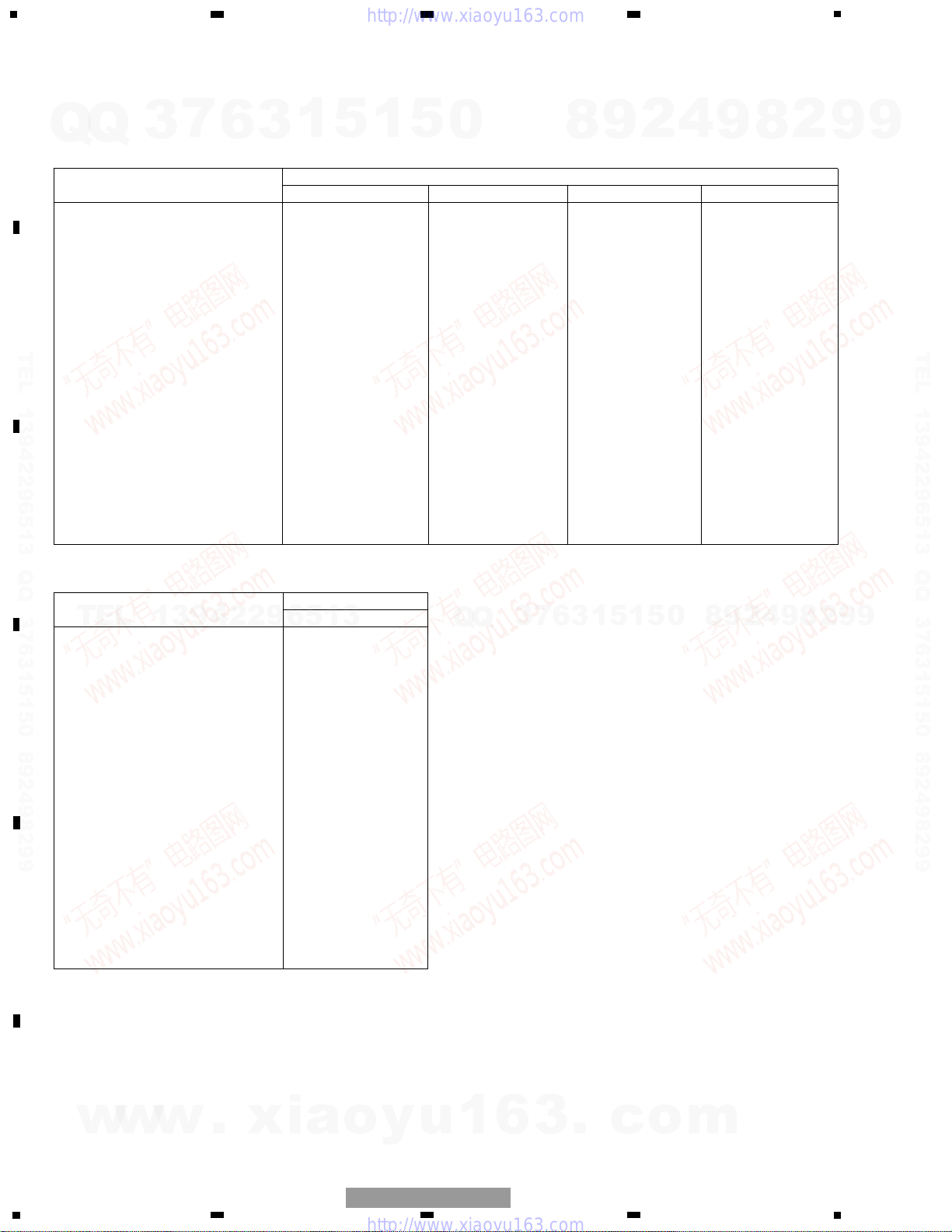
GM-7100M/XU/EW
Part No.
Mark No. Description GM-7150M/XU/UC
* 6 Badge CAH1917
9 Panel CNB3058
10 Panel CNB3114
11 Heat Sink CNR1792
13 Amp Unit CWH1270
16 Pin Jack(CN111) CKB1069
17 Terminal(CN853) CKE1054
18 Terminal(CN855) CKE1056
20 Connector(CN701) CKS4962
41 Remote Control Unit CWM9848
42 Connector(CN1351) CKS4962
43 Screw BPZ20P100FZK
44 Grille CNS8140
45 Cover CNS8141
46 Knob Unit CXC4335
47 Spring CBL1692
48 Remote Control Assy CXC4064
(2) CONTRAST TABLE
GM-7100M/XU/EW, GM-7100M/XU/UC, GM-7100M/XU/ES,GM-7100M/XU/CN and GM-7150M/XU/UC are constructed
the same except for the following:
Part No.
Mark No. Description GM-7100M/XU/EW GM-7100M/XU/UC GM-7100M/XU/ES GM-7100M/XU/CN
* 6 Badge CAH1919 CAH1919 CAH1916 CAH1916
9 Panel CNB3057 CNB3059 CNB3060 CNB3060
10 Panel CNB3125 CNB3061 CNB3124 CNB3124
11 Heat Sink CNR1765 CNR1765 CNR1766 CNR1766
13 Amp Unit CWH1270 CWH1271 CWH1271 CWH1271
16 Pin Jack(CN111) CKB1069 CKB1068 CKB1068 CKB1068
17 Terminal(CN853) CKE1054 CKE1055 CKE1055 CKE1055
18 Terminal(CN855) CKE1056 CKE1057 CKE1057 CKE1057
20 Connector(CN701) CKS4962 Not used Not used Not used
41 Remote Control Unit CWM9848 Not used Not used Not used
42 Connector(CN1351) CKS4962 Not used Not used Not used
43 Screw BPZ20P100FZK Not used Not used Not used
44 Grille CNS8140 Not used Not used Not used
45 Cover CNS8141 Not used Not used Not used
46 Knob Unit CXC4335 Not used Not used Not used
47 Spring CBL1692 Not used Not used Not used
48 Remote Control Assy CXC4064 Not used Not used Not used
Q
Q
3
7
6
3
1
5
1
5
0
8
9
2
4
9
8
2
9
9
TEL 13942296513 QQ 376315150 892498299
TEL
13942296513
Q
Q
3
7
6
3
1
5
1
5
0
8
9
2
4
9
8
2
9
TEL 13942296513 QQ 376315150 892498299
9
w
w
w
.
xia
o
y
u
1
6
3
.
c
o
m
 Loading...