

Page 1
INSTALLATION MANUAL
DVH-P5050MP
INSTALLATION MANUAL
This product conforms to new cord colors.
Los colores de los cables de este producto se conforman con un nuevo código de colores.
English
Español
Page 2

Connecting the Units
Power cable connection 4
Connecting to separately sold power amp 6
When connecting with a multi-channel
processor 8
When connecting the display with RCA
input jack 10
When using a display connected to rear
video output 11
Installation
DIN Front/Rear-mont 12
DIN Front-mont 13
Installation with the rubber bush 13
Removng the unit 13
DIN Rear-mont 14
Installation using the screw holes
on the side of the unit 14
Fixing the front panel 15
Notes
• This unit is for vehicles with a 12-volt battery
and negative grounding. Before installing it in
a recreational vehicle, truck, or bus, check the
battery voltage.
• To avoid shorts in the electrical system, be
sure to disconnect the ≠ battery cable before
beginning installation.
• Refer to the owner’s manual for details on
connecting the power amp and other units,
then make connections correctly.
• Secure the wiring with cable clamps or adhesive tape. To protect the wiring, wrap adhesive
tape around them where they lie against
metal parts.
• Route and secure all wiring so it cannot touch
any moving parts, such as the gear shift,
handbrake, and seat rails. Do not route wiring
in places that get hot, such as near the heater
outlet. If the insulation of the wiring melts or
gets torn, there is a danger of the wiring shortcircuiting to the vehicle body.
• Don’t pass the yellow lead through a hole into
the engine compartment to connect to the
battery. This will damage the lead insulation
and cause a very dangerous short.
• Do not shorten any leads. If you do, the protection circuit may fail to work when it should.
• Never feed power to other equipment by cutting the insulation of the power supply lead of
the unit and tapping into the lead. The current
capacity of the lead will be exceeded, causing
overheating.
• When replacing fuse, be sure to use only fuse
of the rating prescribed on the fuse holder.
• Since a unique BPTL circuit is employed,
never wire so the speaker leads are directly
grounded or the left and right ≠ speaker
leads are common.
Contents Connecting the Units
2
En
Page 3
• Speakers connected to this unit must be highpower types with minimum rating of 50 W and
impedance of 4 to 8 ohms. Connecting speakers with output and/or impedance values
other than those noted here may result in the
speakers catching fire, emitting smoke, or
becoming damaged.
• If the RCA pin jack on the unit will not be
used, do not remove the caps attached to the
end of the connector.
• When this product’s source is switched ON, a
control signal is output through the
blue/white lead. Connect to an external power
amp’s system remote control or the car’s
Auto-antenna relay control terminal (max. 300
mA 12 V DC). If the car features a glass
antenna, connect to the antenna booster
power supply terminal.
• When an external power amp is being used
with this system, be sure not to connect the
blue/white lead to the amp’s power terminal.
Likewise, do not connect the blue/white lead
to the power terminal of the auto-antenna.
Such connection could cause excessive current drain and malfunction.
• To avoid short-circuiting, cover the disconnected lead with insulating tape. Especially,
insulate the unused speaker leads without
fail. There is a possibility of short-circuiting if
the leads are not insulated.
• To prevent incorrect connection, the input
side of the IP-BUS connector is blue, and the
output side is black. Connect the connectors
of the same colors correctly.
• If this unit is installed in a vehicle that does
not have an ACC (accessory) position on the
ignition switch, the red lead of the unit should
be connected to a terminal coupled with ignition switch ON/OFF operations. If this is not
done, the vehicle battery may be drained
when you are away from the vehicle for several hours.
• The black lead is ground. Please ground this
lead separately from the ground of high-current products such as power amps.
If you ground the products together and the
ground becomes detached, there is a risk of
damage to the products or fire.
• Cords for this product and those for other
products may be different colors even if they
have the same function. When connecting
this product to another product, refer to the
supplied Installation manuals of both products and connect cords that have the same
function.
No ACC positionACC position
En
3
English
Español
Deutsch
Français
Italiano
Nederlands
Connecting the Units
C
C
A
O
F
N
F
O
S
T
A
R
T
O
F
N
F
O
S
T
A
R
T
Page 4
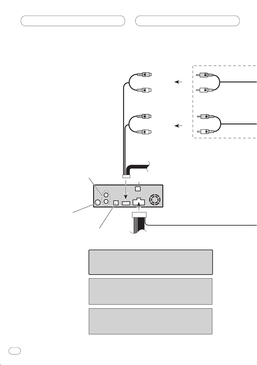
Power cable connection
Connecting the Units
En
4
Fuse holder
Fuse resistor
Fuse resistor
Yellow
To terminal always supplied
with power regardless of
ignition switch position.
Red
To electric terminal controlled
by ignition switch (12 V DC)
ON/OFF.
Black (ground)
To vehicle (metal) body.
Orange/white
To lighting switch terminal.
Yellow/black
If you use a cellular telephone, connect it via the
Audio Mute lead on the cellular telephone. If not,
keep the Audio Mute lead free of any
connections.
IP-BUS cable
This product
Antenna jack
IP-BUS input (Blue)
Optical input
Refer to pages6–11.
Multi-CD player
(sold separately)
Rear audio output
(Refer to pages 8 – 11.)
Page 5
Connecting the Units
En
5
English
Español
Deutsch
Français
Italiano
Nederlands
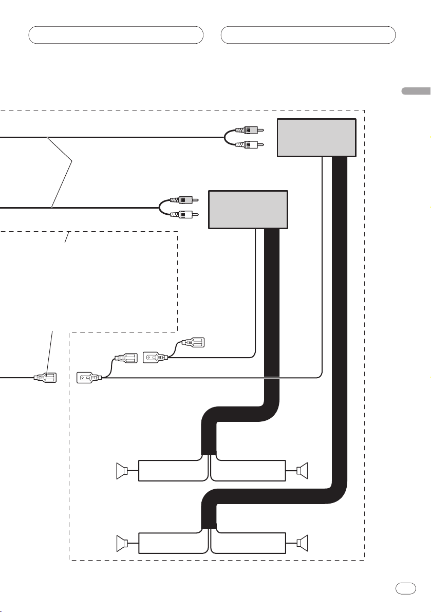
Blue/white
To system control terminal of the power amp
or Auto-antenna relay control terminal
(max. 300 mA 12 V DC).
White
White/black
Gray
Gray/black
Green
Green/black
Violet
Violet/black
Front speaker
Rear speaker
Front speaker
Rear speaker
Left Right
With a 2 speaker system, do not connect anything
to the speaker leads that are not connected to speakers.
+
≠
+
≠
+
≠
+
≠
Light green
Used to detect the ON/OFF status of the parking brake.
This lead must be connected to the power supply side of the
parking brake switch.
Parking brake
switch
Power supply side
Ground side
Note
• The position of the parking brake switch depends
on the vehicle model. For details, consult the
vehicle Owner’s Manual or dealer.
Connection method
Clamp the lead.1. 2. Clamp firmly with
needle-nosed
pliers.
When you connect separately sold multi-channel processor
(DEQ-P7050) to this unit, do not connect anything to the
speaker leads and system remote control (blue/white).
Page 6
Connecting the Units
En
6
System remote control
Subwoofer output
or non fading output
(SUBWOOFER OUTPUT or
NON-FADING OUTPUT)
Front output
(FRONT OUTPUT)
15 cm
15 cm
Note
Change the initial setting of this product (refer to the
Operation Manual). The subwoofer output of this unit
is monaural.
Note
When you connect DEQ-P7050 to this unit, separately
sold power amp must be connected to DEQ-P7050.
This product
Optical input
Antenna jack
(Refer to page 4.)
IP-BUS input (Blue)
(Refer to page 4.)
When you connect separately sold multi-channel
processor (DEQ-P7050) to this unit, do not connect
anything to the speaker leads and system remote
control (blue/white).
Rear audio output
(Refer to pages 8 – 11.)
Connecting to separately sold power amp
Page 7
Connecting the Units
En
7
English
Español
Deutsch
Français
Italiano
Nederlands
Use this for connections when
you have the separately available
amplifier.
Blue/white
To system control terminal of the
power amp or Auto-antenna relay
control terminal
(max. 300 mA 12 V DC).
Subwoofer
Subwoofer
Front speaker
Front speaker
Connecting cords
with RCA pin plugs
(sold separately)
Left Right
System remote control
≠
+
≠
+
≠
+
≠
+
Power amp
(sold separately)
Power amp
(sold separately)
Page 8
Connecting the Units
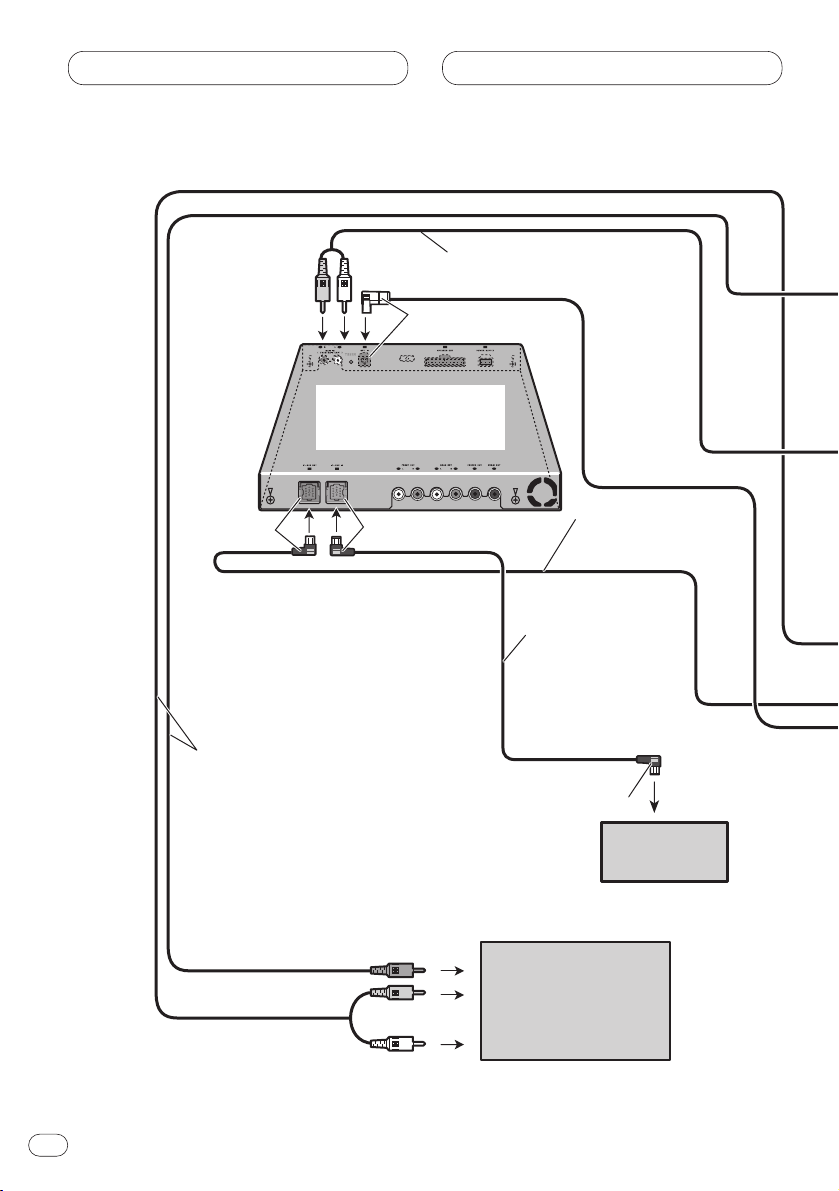
When connecting with a multi-channel processor
En
8
To audio
inputs
To video
input
Yellow
Right (Red)
Left (White)
IP-BUS cable
(supplied with
multi-CD player)
Black
Blue
IP-BUS cable
(supplied with
multi-channel processor)
Blue
Black
RCA cables
(sold separately)
RCA cable
(supplied with multi-channel processor)
Multi-CD player
(sold separately)
Multi-channel processor
(DEQ-P7050)
(sold separately)
Display with RCA
input jacks
Page 9
Connecting the Units
En
9
English
Español
Deutsch
Français
Italiano
Nederlands
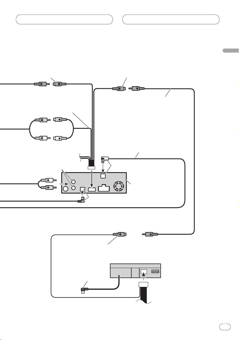
Rear video output
(REAR VIDEO OUTPUT)
(Yellow) (23 cm)
Optical cable
(supplied with multi-channel processor)
Right (Red)
Left (White)
RCA cable (supplied)
Rear audio output
Right (Red)
Left (White)
6m
1.5 m
Not used.
AV system display
(e.g. AVX-7300)
(sold separately)
Video input
(VIDEO INPUT)
(Yellow)
Front video output
(FRONT VIDEO
OUTPUT) (Yellow)
(23 cm)
Subwoofer output or non fading
output (SUBWOOFER OUTPUT
or NON-FADING OUTPUT) (15cm)
This product
Black
Blue
Page 10
Connecting the Units
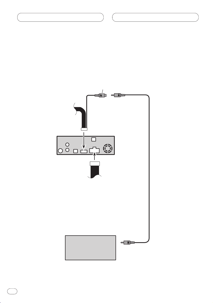
When connecting the display with RCA input jack
En
10
RCA cable
(supplied)
To video input
Display with RCA
input jacks
1.5 m
This product
Front video output
(FRONT VIDEO OUTPUT)
23 cm
Page 11
Connecting the Units
En
11
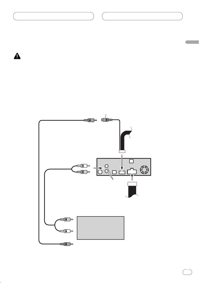
When using a display connected to rear video output
This product’s rear video output is for connection of a display to enable passengers in the rear seats
to watch the DVD or Video CD.
WARNING
• NEVER install the display in a location that enables the driver to watch the DVD or Video CD while
driving.
• NEVER connect rear audio output to sold separately power amp.
English
Español
Deutsch
Français
Italiano
Nederlands
Display with RCA
input jacks
RCA cable
(supplied)
To video input
To audio inputs
RCA cable
(sold separately)
1.5 m
This product
Rear video output
(REAR VIDEO OUTPUT)
23 cm
Rear audio output
Left (White)
Right (Red)
Page 12
Installation
Notes
• Before finally installing the unit, connect the
wiring temporarily, making sure it is all connected up properly, and the unit and the system work properly.
• Use only the parts included with the unit to
ensure proper installation. The use of unauthorized parts can cause malfunctions.
• Consult with your nearest dealer if installation
requires the drilling of holes or other modifications of the vehicle.
• Install the unit where it does not get in the
driver’s way and cannot injure the passenger
if there is a sudden stop, like an emergency
stop.
• The semiconductor laser will be damaged if it
overheats, so don’t install the unit anywhere
hot — for instance, near a heater outlet.
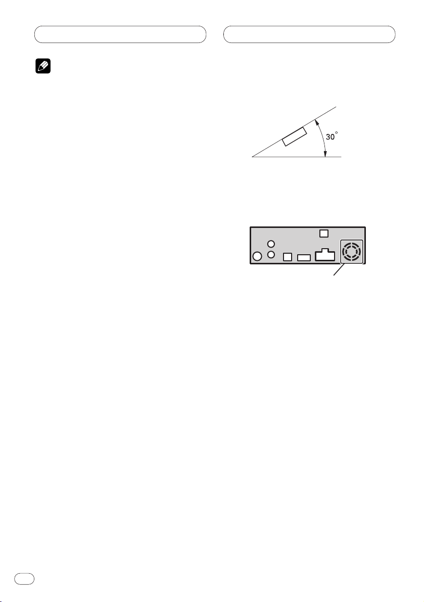
• If installation angle exceeds 30° from horizontal, the unit might not give its optimum performance.
• The cords must not cover up the area shown
in the figure below. This is necessary to allow
the amplifires to radiate freely.
Do not close this area.
En
12
DIN Front/Rear-mount
This unit can be properly installed either from “Front” (conventional DIN Front-mount) or “Rear”
(DIN Rear-mount installation, utilizing threaded screw holes at the sides of unit chassis). For
details, refer to the following illustrated installation methods.
Page 13
Installation
En
13
English
Español
Deutsch
Français
Italiano
Nederlands
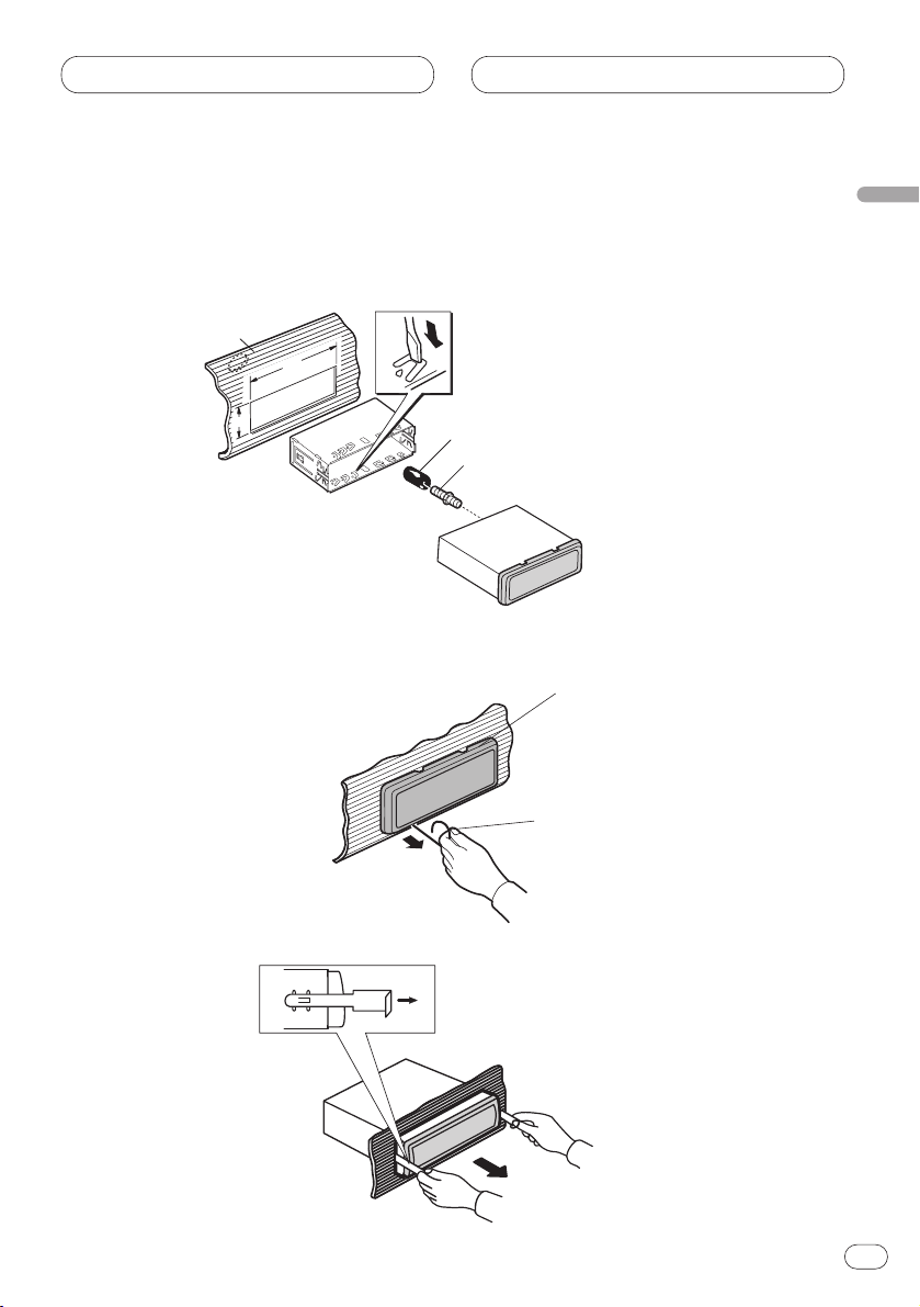
DIN Front-mount
Installation with the rubber bush
Removing the unit
Holder
After inserting the holder into the
dash-board, then select the
appropriate tabs according to the
thickness of the dash-board
material and bend them.
(Install as firmly as possible using
the top and bottom tabs. To secure,
bend the tabs 90 degrees.)
182
53
Rubber bush
Screw
Dashboard
Frame
Insert the release pin into the hole
in the bottom of the frame and pull
out to remove the frame. (When
reattaching the frame, point the
side with a groove downwards and
attach it.)
Insert the supplied extraction keys into the
unit, as shown in the figure, until they click
into place. Keeping the keys pressed against
the sides of the unit, pull the unit out.
Page 14
Installation
DIN Rear-mount
Installation using the screw holes on the side of the unit
1. Remove the frame.
2. Fastening the unit to the factory radio mounting bracket.
Select a position where the screw holes of the
bracket and the screw holes of the head unit
become aligned (are fitted), and tighten the
screws at 2 places on each side. Use either
truss screws (5 × 8 mm) or flush surface screws
(5 × 9 mm), depending on the shape of the
screw holes in the bracket.
En
14
Frame
Insert the release pin into the hole in the
bottom of the frame and pull out to remove
the frame. (When reattaching the frame,
point the side with a groove downwards and
attach it.)
Screw
Factory radio
mounting bracket
Dashboard or Console
Page 15

Installation
En
15
Fixing the front panel
If you do not operate the Detaching and Replacing the Front Panel Function, use the supplied fixing
screws and holder to fix the front panel to this unit.
1. Attach the holders to both sides of the front panel.
2 Replace the front panel to the unit.
3. Flip the holders into upright positions.
4 Fix the front panel to the unit using fixing screws.
English
Español
Deutsch
Français
Italiano
Nederlands
Holder
Fixing screw
Page 16

Conexión de las unidades
Conexión del cable de alimentación 4
Conexión al amplificador de potencia ven-
dido separadamente 6
Cuando conecte con un procesador multi-
canal 8
Cuando conecte la presentación visual con
tomas de entrada RCA 10
Cuando utilice un presentación visual
conectado a la salida de vídeo trasera 11
Instalación
Montaje delantero/trasero DIN 12
Montaje delantero DIN 13
Instalación con tope de goma 13
Quitado de la unidad 13
Montaje trasero DIN 14
Instalación usando los agujeros para
tornillos ubicados en ambos costados
de la unidad 14
Colocación del panel delantero 15
Notes
• Esta unidad es para vehículos con batería de
12 voltios y con conexión a tierra. Antes de
instalar la unidad en un vehículo recreativo,
camioneta, o autobús, revise el voltaje de la
batería.
• Para evitar cortocircuitos en el sistema eléctrico, asegúrese de desconectar el cable de la
batería ≠ antes de comenzar con la instalación.
• Consulte con el manual del usuario para los
detalles sobre la conexión de la alimentación
de amperios y de otras unidades, luego haga
las conexiones correctamente.
• Asegure el cableado con abrazaderas de
cables o con cinta adhesiva. Para proteger el
cableado, envuélvalo con cinta adhesiva donde
éstos se apoyan sobre las piezas de metal.
• Coloque y asegure todo el cableado de tal
manera que no toque las piezas en
movimiento, tal como la palanca de cambio
de velocidades, el freno de mano, y los
pasamanos de los asientos. No coloque el
cableado en lugares que se calientan, tal
como cerca de la salida de un calefactor. Si el
material aislante del cableado se derritiera o
se gastara, habrá el peligro de un cortocircuito
del cableado a la carrocería del vehículo.
• No pase el conductor amarillo a través de un
orificio en el compartimiento del motor para
conectar a la batería. Esto dañará el material
aislante del conductor y causará un cortocircuito peligroso.
• No acorte ningún conductor. Si lo hiciera, la
protección del circuito podría fallar al funcionar cuando debería.
• Nunca alimente energía a otros equipos cortando el aislamiento del conductor de alimentación provista de la unidad y haciendo
un empalme con el conductor. La capacidad
de corriente del conductor se excederá, causando el recalentamiento.
• Cuando reemplace el fusible, asegúrese de
utilizar solamente un fusible del régimen
nominal prescrito en el soporte de fusibles.
Contenido Conexión de las unidades
2
Sp
Page 17

• Ya que se emplea un circuito único BPTL,
nunca coloque los cables de manera que los
conductores del altavoz estén directamente
en conexión a tierra o que el altavoz izquierdo
y derecho ≠ sean comunes.
• Los altavoces conectados a esta unidad
deberán ser del tipo de alta potencia,
teniendo un régimen mínimo de 50 W y una
impedancia de 4 a 8 ohmios. La conexión de
altavoces con valores de impedancia y/o de
salida diferentes a los anotados aquí podrían
causar fuego, emisión de humo o daños a los
altavoces.
• Si la toma de clavija RCA en la unidad no se
usa, retire las tapas fijadas al extremo del
conector.
• Cuando se conecta la fuente de este
producto, una señal de control se emite a
través del conductor azul/blanco. Conecte al
control remoto de sistema de un amplificador
de potencia externo o al terminal de controle
de relé de antena automática del vehículo
(máx. 300 mA 12 V CC). Si el vehículo tiene
una antena en vidrio, conecte al terminal de
suministro de energía de la antena.
• Cuando se está utilizando un amperio de
potencia externa con este sistema, asegúrese
de no conectar el conductor azul/blanco al
terminal de potencia de amperios. Asimismo,
no conecte el conductor azul/blanco al terminal de potencia de la auto-antena. Tal conexión podría causar la fuga de corriente excesiva y causar fallos de funcionamiento.
• Para evitar cortocircuitos, cubra el conductor
desconectado con cinta aislada.
Especialmente, aísle los conductores de
altavoz no usados. Hay la posibilidad de cortocircuito si no se aíslan los conductores.
• Para evitar la conexión incorrecta, el lado de
entrada del conector IP-BUS es azul, y el lado
de salida es negro. Conecte los conectores
del mismo color correctamente.
• Si se instala esta unidad en un vehículo que
no tiene una posición ACC (accesorio) en el
interruptor de encendido, el conductor rojo de
la unidad deberá conectarse al terminal
conectado con las operaciones del interruptor
de encendido ON/OFF. Si no se hace esto, la
batería del vehículo podría drenarse cuando
usted esté lejos del vehículo por varias horas.
• El conductor negro es la masa. Conecte a
masa este conductor separadamente desde la
masa de los productos de alta corriente tal
como los amplificadores de potencia.
Si conecta juntos a masa los productos y la
masa se desconecta, se crea el riesgo de
daños a los productos o de incendios.
• Los cables para esta unidad y aquéllas para
las unidades pueden ser de colores
diferentes aun si tienen la misma función.
Cuando se conecta esta unidad a otra,
refiérase a los manuales de instalación de
ambas unidades y conecte los cables que
tienen la misma función.
No en la posición ACC
Posición ACC
Sp
3
English
Español
Deutsch
Français
Italiano
Nederlands
Conexión de las unidades
C
C
A
O
F
N
F
O
R
T
S
T
A
O
F
N
F
O
S
T
A
R
T
Page 18

Conexión del cable de alimentación
Conexión de las unidades
Sp
4
Portafusible
Resistencia
de fusible
Resistencia
de fusible
Amarillo
Al terminal con suministro
constante de electricidad,
independientemente de la posición
del interruptor de encendido.
Rojo
Al terminal de energía eléctrica controlado
por el interruptor de encendido del vehículo
(12 V de CC.) ON/OFF.
Negro (masa)
A la carrocería del veículo (parte metálica).
Anaranjado/blanco
Al terminal de interruptor de iluminación.
Reproductor de
Multi-CD (en venta
por separado)
Amarillo/negro
Si utiliza un teléfono celular, conéctelo por el
cable de enmudecimiento de audio del teléfono
celular. Si no, mantenga el enmudecimiento de
audio libre de cualquier conexión.
Cable IP-BUS
Este producto
Jack para antena
Entrada IP-Bus (Azul)
Entrada óptica
Cousulte las páginas 6 – 11.
Salida de audio trasera
(Cousulte las páginas 8 – 11.)
Page 19

Conexión de las unidades
Sp
5
English
Español
Deutsch
Français
Italiano
Nederlands
Azul/blanco
Al terminal de control de sistema del amp. de
potencia o control de relé de antena
automática (máx. 300 mA de 12 V CC).
Blanco
Blanco/negro
Gris
Gris/negro
Verde
Verde/negro
Violeta
Violeta/negro
Altavoz
delantero
Altavoz
trasero
Altavoz
delantero
Altavoz
trasero
Izquierda Derecha
Con un sistema de 2 altavoces, no conecte a los conductores
de los altavoces nada que no se conecten a los altavoces.
+
≠
+
≠
+
≠
+
≠
Verde claro
Se utiliza para detectar el estado ON/OFF del freno de mano.
Este cable debe conectarse al lado de alimentación del
interruptor del freno de mano.
Interruptor del
freno de mano
Lado de alimentación
Lado de masa
Nota
• La posición del freno de estacionamiento depende del
modelo del vehículo. Para conocer detalles, consulte el
manual del propietario del vehículo o a su concesionario.
Método de conexión
Apriete el cable.1. 2. Apriete
firmemente con
alicates de punta
de aguja.
Cuando conecte el procesador multicanal (DEQ-P7050) vendido
separadamente a esta unidad, no conecte nada a los conductores
de los altavoces y al control remoto del sistema (azul/blanco).
Page 20

Conexión de las unidades
Sp
6
Control remoto de sistema
Salida de altavoz de graves
secundario o salida sin atenuación
(SUBWOOFER OUTPUT or
NON-FADING OUTPUT)
Salida delantera
(FRONT OUTPUT)
15 cm
15 cm
Nota
Cambie el ajuste inicial de este producto (refiérase al
manual de operación). La salida del altavoz de graves
secundario es monaural.
Nota
Cuando conecte el DEQ-P7050 a esta unidad, se deberá
conectar el amplificador de potencia vendido
separadamente al DEQ-P7050.
Este producto
Entrada óptica
Jack para antena
(Cousulte la página 4.)
Entrada IP-Bus (Azul)
(Cousulte la página 4.)
Cuando conecte el Procesador Multicanal (DEQ-P7050)
vendido separadamente a esta unidad, no conecte nada
a los conductores de los altavoces y al control remoto del
sistema (azul/blanco).
Salida de audio trasera
(Cousulte las páginas 8 – 11.)
Conexión al amplificador de potencia vendido separadamente
Page 21

Conexión de las unidades
Sp
7
English
Español
Deutsch
Français
Italiano
Nederlands
Lleve a cabo las conexiones cuando
utilice un amplificador diferente.
Azul/blanco
Al terminal de control de sistema del
amp. de potencia o control de relé
de antena automática (máx. 300 mA
de 12 V CC).
Altavoz secundario
Altavoz delantero
Cables de conexión con
clavijás RCA
(en venta por separado)
Izquierda Derecha
Control remoto de sistema
Altavoz secundario
Altavoz delantero
≠
+
≠
+
≠
+
≠
+
Amplificador de
potencia (en venta
por separado)
Amplificador de
potencia (en venta
por separado)
Page 22

Conexión de las unidades
Cuando conecte con un procesador multicanal
Sp
8
A las entradas
de audio
A la entrada
de vídeo
Amarillo
Derecha (Rojo)
Izquierda (Blanco)
Cable IP-BUS
(suministrado con el
reproductor de
multi-CD)
Negro
Azul
Cable IP-BUS
(suministrado con el
procesador multicanal)
Azul
Negro
Cable RCA
(vendido separadamente)
Cable RCA
(suministrado con el procesador multicanal)
Procesador Multicanal
(DEQ-P7050)
(vendido separadamente)
Presentación visual
con tomas de
entrada RCA
Reproductor de
Multi-CD (en venta
por separado)
Page 23

Conexión de las unidades
Sp
9
English
Español
Deutsch
Français
Italiano
Nederlands
Salida de vídeo trasera
(REAR VIDEO OUTPUT)
(Amarillo) (23 cm)
Cable óptico
(suministrado con el
procesador multicanal)
Derecha (Rojo)
Izquierda (Blanco)
Cable RCA
(suministrado)
Salida de audio trasera
Derecha (Rojo)
Izquierda (Blanco)
6 m
1.5 m
No se usa
Pantalla de visualización de
sistema de AV
(AVX-7300, por ejemplo)
(vendido separadamente)
Entrada de vídeo
(VIDEO INPUT)
(Amarillo)
Salida de vídeo
delantera (FRONT
VIDEO OUTPUT)
(Amarillo) (23 cm)
Salida de altavoz de graves
secundario o salida sin atenuación
(SUBWOOFER OUTPUT or NONFADING OUTPUT) (15cm)
Este producto
Negro
Azul
Page 24

Conexión de las unidades
Cuando conecte la presentación visual con tomas de entrada RCA
Sp
10
Cable RCA
(suministrado)
A la entrada
de video
Presentación visual
con tomas de
entrada RCA
1.5 m
Este producto
Salida de vídeo delantera
(FRONT VIDEO OUTPUT)
23 cm
Page 25

Conexión de las unidades
Sp
11
Cuando utilice un presentación visual conectado a la salida de
vídeo trasera
La salida de vídeo trasera de este producto es para la conexión de un presentación visual para permitir que los pasajeros en los asientos traseros puedan ver el DVD o Video CD.
ADVERTENCIA
• NUNCA instale el presentación visual en un lugar que permita el motorista ver el DVD o Video CD
mientras conduce el automóvil.
• NUNCA conecte la salida de audio trasera al amplificador de potencia vendido separadamente.
English
Español
Deutsch
Français
Italiano
Nederlands
Cable RCA
(suministrado)
A la entrada de video
A las entradas
de audio
Cable RCA
(vendido separadamente)
1.5 m
Este producto
Salida de vídeo trasera
(REAR VIDEO OUTPUT)
23 cm
Salida de audio
trasera
Derecha (Rojo)
Izquierda (Blanco)
Presentación visual
con tomas de
entrada RCA
Page 26

Instalación
Notas
• Antes de finalmente instalar la unidad,
conecte el cableado temporalmente y
asegúrese de que todo esté conectado correctamente y que la unidad y el sistema funcionan debidamente.
• Utilice sólo las piezas que se incluyen con
esta unidad para asegurar la instalación adecuada. El uso de piezas no autorizadas podría
causar fallos de funcionamiento.
• Consulte con su distribuidor si la instalación
requiere del taladro de orificios u otras modificaciones del vehículo.
• Instale la unidad donde no alcance el espacio
del conductor, y donde no pueda dañar a los
pasajeros si sucediera un paro repentino,
como una detención de emergencia.
• El semiconductor láser se dañará si se sobrecalienta, por eso no instale la unidad en un
lugar caliente – por ejemplo, cerca de la salida de un calefactor.
• Si el ángulo de la instalación excede los 30°
del lado horizontal, la unidad podría no
brindar su óptimo funcionamiento.
• Los cordones no deben tapar el área
mostrado en la figura de abajo. Esto es necesario para permitir que los amplificadores
puedan radiar libremente.
Evite cerrar este área.
Sp
12
Montaje delantero/trasero DIN
Esta unidad quede instalarse correstamente de la “Delantera” (montaje delantero DIN convenciona) o “Trasera” (montaje trasero DIN, utilizando los tornillos roscados en los constados del
chasis de la unidad). Para detalles, refiérase a los métodos de instalación ilustrados abajo.
Page 27

Instalación
Sp
13
English
Español
Deutsch
Français
Italiano
Nederlands
Montaje delantero DIN
Instalación con tope de goma
Quitado de la unidad
182
53
Marco
Inserte el pasador de liberanción en
el orificio de la parte inferior del
marco, y tire hacia afuera para
extraer el marco. (Para la fijación
del marco, apunte el lado con ranura hacia abajo.)
Inserte las herramientas de extracción suministradas en la unidad, como se indica en la
figura, hasta que se enganchen en su positión. Tire de la unidad mientras mantiene las
herramientas presionadas contra los lados
de la unidad.
Soporte
Después de insertar el soporte en la tabla de
mandos, luego seleccione las orejetas
apropiadas según el grosor del material de la
tabla de mandos y dóblelos.
(Instale lo más firme posible usando las
lengüetas superior e inferior. Para fijar,
doble las lengüetas 90 grados.)
Tope de goma
Tablero de
instrumentos
Tornillo
Page 28

Instalación
Montaje trasero DIN
Instalación usando los agujeros para tornillos ubicados en ambos costados de
la unidad
1 Quite el marco.
2 Fijación de la unidad a la ménsula de montaje existente.
Seleccione una posición en la que los orificios
para los tornillos del soporte y del de la unidad
principal queden alineados, y apriete los tornillos en 2 lugares de un lado. Utilice ya sea los
tornillos de fijación (5 × 8 mm) o los tornillos a
paño (5 × 9 mm), dependiendo de la forma de
los orificios de tornillo en la ménsula.
Sp
14
Marco
Inserte el pasador de liberanción en el orificio
de la parte inferior del marco, y tire hacia
afuera para extraer el marco. (Para la fijación
del marco, apunte el lado con ranura hacia
abajo.)
Tornillo
Ménsula de montaje
de radio existente
Tablero de instrumentos
o consola
Page 29

Instalación
Sp
15
Colocación del panel delantero
Si no desea utilizar la función de extracción y colocación del panel delantero, utilice los tornillos de
fijación y sujetadores suministrados y fije el panel delantero a esta unidad.
1. Coloque los sujetadores en ambos lados del panel delantero.
2. Reinstale el panel delantero en la unidad.
3. Mueva los sujetadores en las posiciones verticales.
4. Fije el panel delantero a la unidad utilizando los tornillos de fijación.
English
Español
Deutsch
Français
Italiano
Nederlands
Sujetador
Tornillos de fijación
Page 30

目錄
設備連接
電源線連接 4
連接另售的功率放大器 6
連接多聲道處理器 8
連接帶RCA輸入插口的顯示器時 10
使用連至後置視頻輸出的顯示器 11
安裝
DIN前面安裝後面安裝 12
DIN前面安裝 13
使用橡膠襯套安裝 13
移走本機 13
DIN後面安裝 14
使用本機側面的螺絲孔進行安裝 14
固定前面板 15
設備連接
÷
本機用於具12伏電池和負接地的車輛。
在將本產品安裝於旅遊車,貨車或公共
汽車前,請檢查電池電壓。
÷
為了避免電氣系統短路,請確保在開始
安裝前斷開電池·端的電纜。
÷
請參閱用戶的使用說明書,獲取有關連
接功率放大器和其它設備的詳情,然後
再作正確的連接。
÷
請用電纜夾或膠帶固定接線。為了保護
接線,請將膠帶纏繞在接線與金屬部件
觸碰的部位。
÷
請注意布線並固定所有接線,以使其無
法觸碰到任何移動部件,如變速桿,手
剎車和座椅固定導軌。請勿將接線排布
在熱源區域,例如暖氣排放口附近。如
果接線的絕緣層熔化或磨損,則會有接
線與車身短路的危險。
÷
請勿將黃色引線穿過安裝孔引入引擎艙
再接至電池。否則,會損壞引線絕緣,
引起十分危險的短路。
÷
請勿剪短任何引線。否則,保護電路可
能無法正常工作。
÷
切勿剝掉本機電源線的絕緣層分接其它
引線,將電源供至其它設備。否則,引
線過載會造成過熱。
÷
更換保險絲時,務必只使用保險絲座上
規定的定額電流的保險絲。
÷
由於採用了獨特的BPTL電路,無需連
線,所以揚聲器引線可直接接地或共用
左右·揚聲器引線。
ChH
2
Page 31

設備連接
÷
連接至本機的揚聲器必須是大功率型,
其最小額定值為50瓦,阻抗為4至8歐。
將揚聲器與輸出端相連和或阻抗值在
此間要求範圍之外,則可能引發揚聲器
起火,冒煙或損壞。
÷
如果不使用本機上的RCA插腳插頭,請不
要取下連接器端頭上的帽蓋。
÷
當本產品的播放源打開時,控制信號通
過藍色白色引線輸出。請連接至外接
功率放大器的系統遙控器或汽車的自動
天線中繼控制端子(最大300mA
12VDC)。如果汽車具有透鏡天線,請連
接至天線放大器電源端子。
÷
當本系統使用了外接功率放大器時,請
勿將藍色白色引線連接至放大器電源
端子。同樣請勿將藍色白色引線連接
至自動天線的電源端子。否則,會產生
漏電流和故障。
÷
為了避免短路,請用絕緣膠帶將未連接
的引線包住。尤其注意,一定要讓未使
用的揚聲器引線絕緣。如果引線未絕
緣,可能引起短路。
÷
IP-BUS連接器的輸入端為藍色,輸出端
為黑色,以防止連接錯誤。請正確連接
相同顏色的連接器。
÷
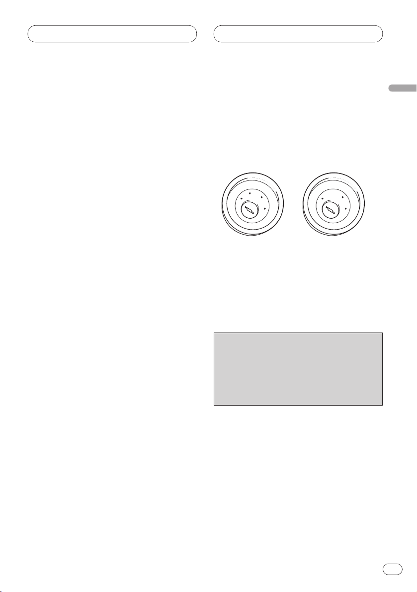
在車輛中安裝時,如果在點火開關上沒
有ACC(配件)位置,則應將本機的紅色
引線連接到與點火開關ON/OFF操作耦聯
的一端。否則,當車輛數小時擱置不用
時就會使車輛電瓶電力耗盡。
C
C
A
O
F
N
F
O
S
T
A
R
T
O
F
N
F
O
S
T
A
R
T
沒有ACC位置ACC位置
÷
黑色引線是接地線。請將此線與大電流
產品(如功率放大器)分開接地。
如果您將這些產品在一處接地,而接地
線又鬆動脫落,則產品可能會損壞或引
起火災。
÷
本產品和其它產品的引線即使作用相
同,顏色也可能不同。當本產品與其
它產品相連接時,請參閱這兩個產品
附帶的安裝說明書,連接功能相同的
引線。
ChH
3
Page 32

設備連接
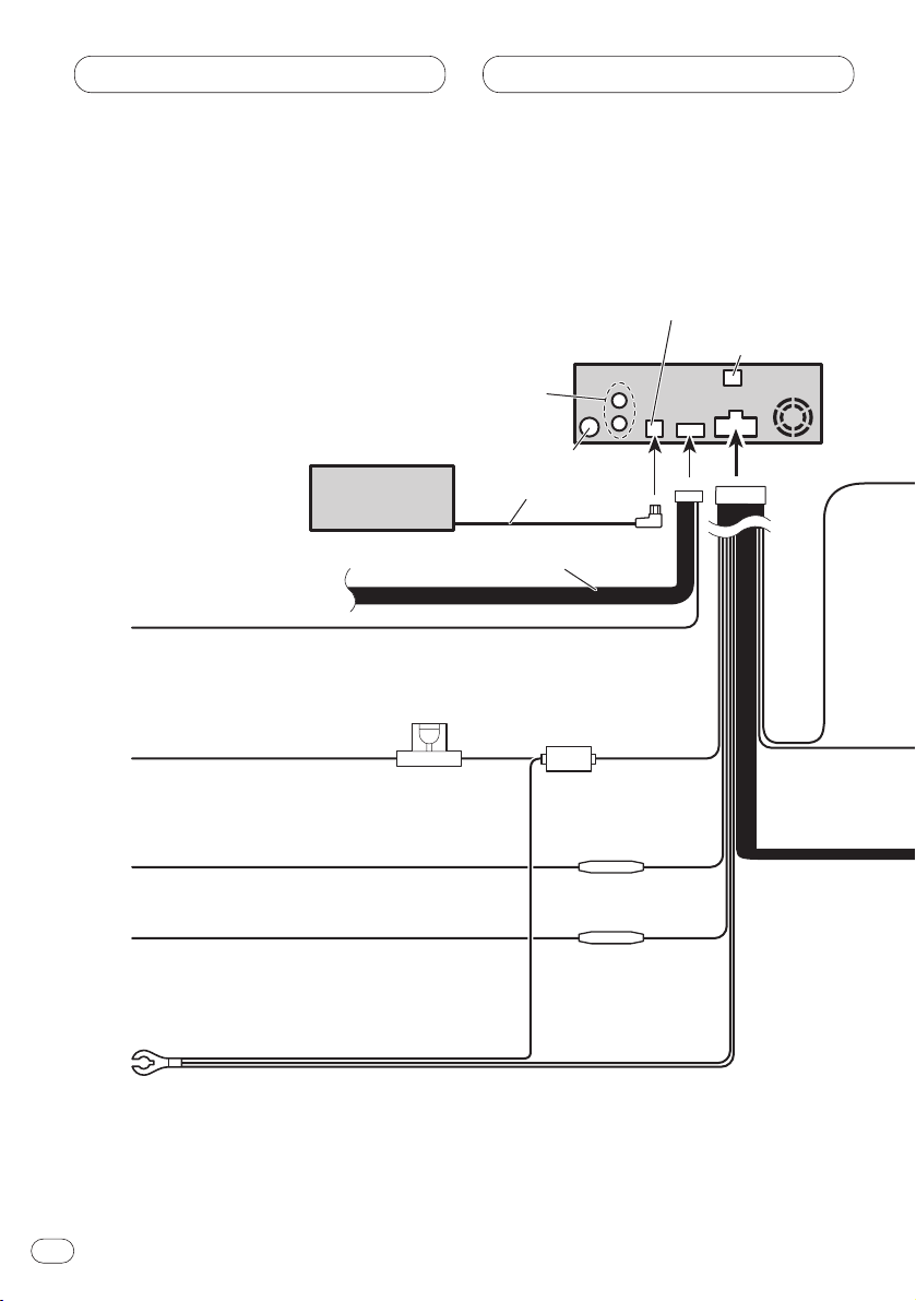
電源線連接
IP-BUS輸入(藍色)
後置音頻輸出
(參閱第8-11頁。)
天線插口
多碟CD播放機
(另售)
黃色黑色
如果您使用移動電話,則通過音頻靜音線將其連接到移動電
話上。反之,則使音頻靜音線空置,不進行任何連接。
黃色
不管點火開關位置在
哪一檔,至一直需要
電源的端子。
橙色白色
接至點火開關端子。
紅色
接至由點火開關(12 VDC)
ON/OFF控制的電氣端子。
保險絲座
IP-BUS電纜
參閱第6-11頁。
本產品
保險絲電阻
保險絲電阻
光纖輸入
黑色(接地)
接至車身(金屬)。
ChH
4
Page 33

設備連接
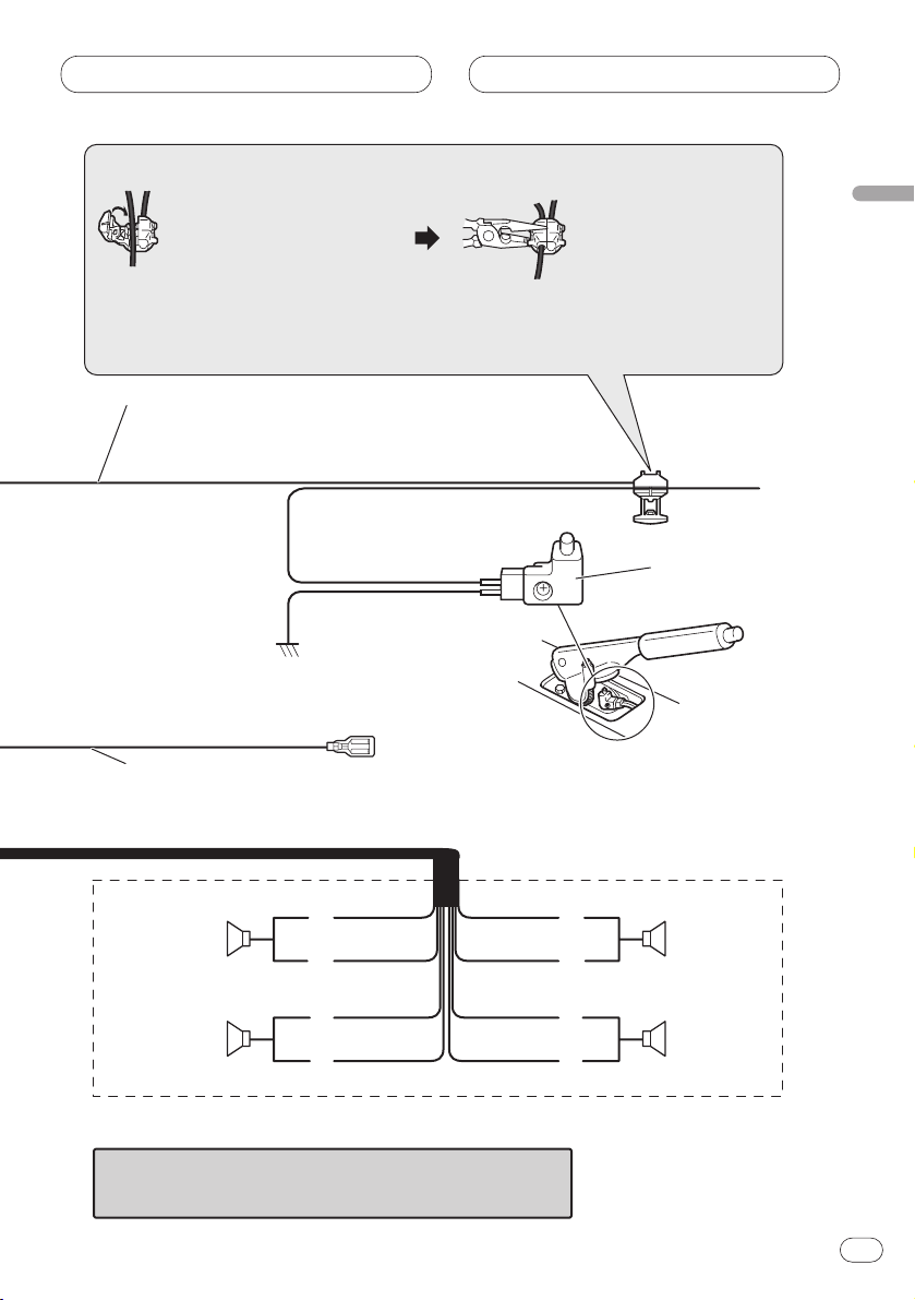
連接方法
1. 夾住引線。
注意
÷
手剎車開關位置根據車輛類型而有所不同。
詳情請咨詢車輛的用戶手冊或經銷商。
淺綠色
用於檢測手剎車ON/OFF狀態。該引線
必須連接至手剎車開關的電源端。
電源端
接地端
藍色/白色
接至自動天線中繼控制端子
(最大300Ma 12VDC)。
2. 用尖頭鉗夾緊。
手剎車開關
前置揚聲器 前置揚聲器
左右
+
≠
白色/黑色
綠色
白色
後置揚聲器
+
≠
綠色/黑色
灰色
灰色/黑色
紫色
紫色/黑色
+
≠
+
≠
後置揚聲器
在2揚聲器系統中,切勿用未連接揚聲器的引線連接其它設備。
當您連接獨立購買的多聲道處理器(DEQ-P7050)至本機
時,請勿將任何設備和揚聲器引線及本機的系統遙控器
相連(藍色白色)。
ChH
5
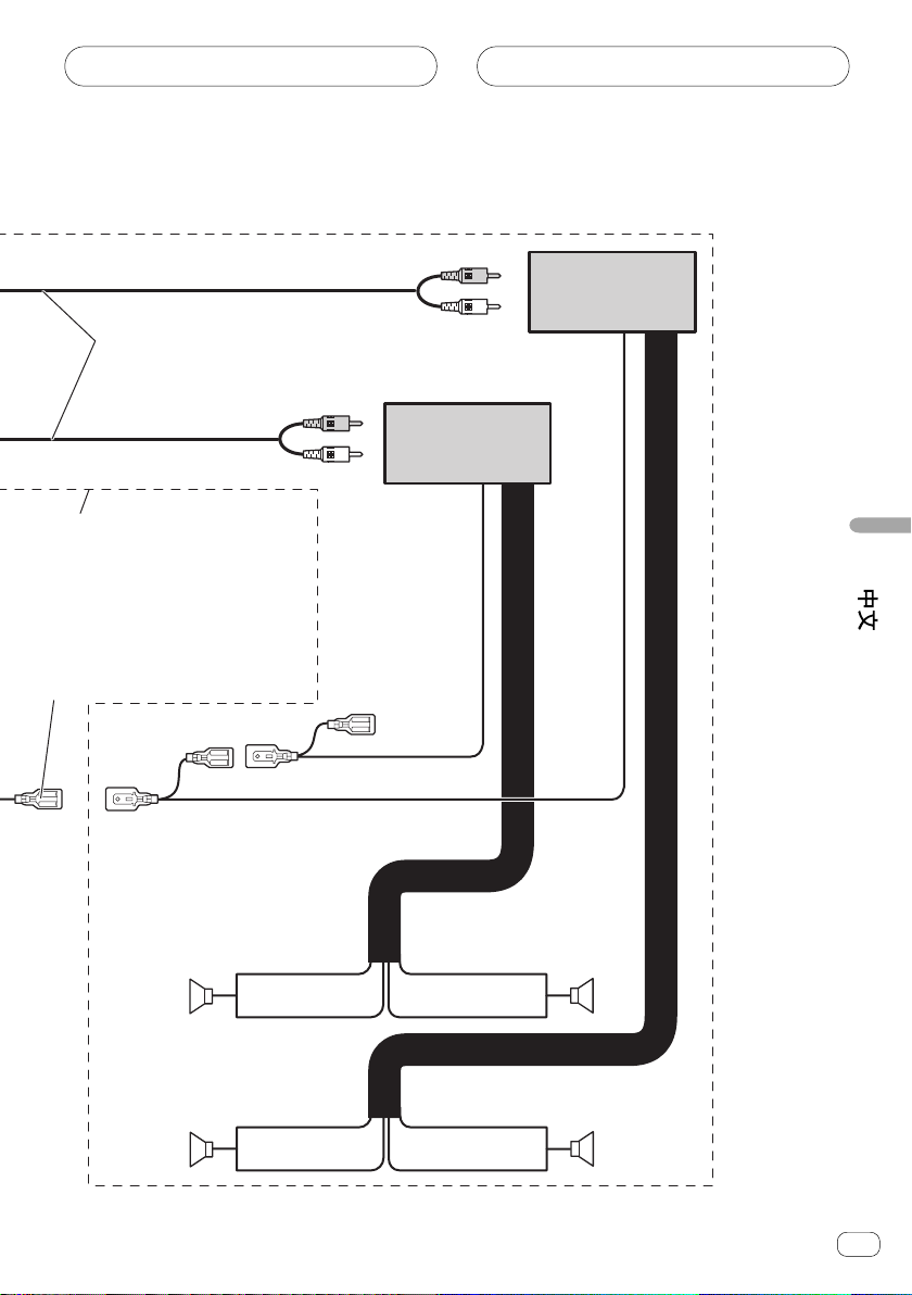
Page 34

設備連接
15 cm
15 cm
連接另售的功率放大器
後置音頻輸出
(參閱第8-11頁。)
本產品
前置輸出
(FRONT OUTPUT)
重低音揚聲器輸出
或無衰減輸出
(SUBWOOFER OUTPUT or
NON-FADINGOUTPUT)
光纖輸入
天線插口
(參閱第4頁。)
IP-BUS輸入(藍色)
(參閱第4頁。)
當您連接獨立購買的多聲道處理器(DEQ-P7050)
至本機時,請勿將任何設備和揚聲器引線及本機
的系統遙控器相連(藍色白色)。
注意
當DEQ-P7050与該單元連接時,獨立購買的功放
必須与DEQ-P7050相連接。
注意
改便了此產品的原始設定(請參照本操作說明
書)。此裝置的重低音輸出為非立體聲。
ChH
6
系統遙控器
Page 35
設備連接
連接帶RCA插腳插
頭的電纜(另售)
當您使用另售的放大
器時使用本接線。
藍色白色
連接与功放上的系統控制終端或
自動天線繼電器控制終端上。
功率放大器
(另售)
功率放大器
(另售)
系統遙控器
左
+
≠
+
≠
重低音揚聲器重低音揚聲器
前置揚聲器前置揚聲器
+
≠
+
≠
右
ChH
7
Page 36

設備連接
連接多聲道處理器
黑色
RCA 電纜(多聲道處理機附帶)
藍色
多聲道處理機
(DEQ-P7050)
(另售)
藍色
IP-BUS電纜
(隨多碟CD播放機附帶)
IP-BUS電纜
(隨多聲道
處理機附帶)
RCA電纜
(另售)
至視頻輸入
至音頻輸入
ChH
8
黃色
右(紅色)
左(白色)
帶RCA輸入插口
的顯示器
黑色
多碟CD播放機
(另售)
Page 37

設備連接
後置視頻輸出
(REAR VIDEO OUTPUT)
(黃色)(23cm)
重低音揚聲器輸出或無衰減輸出
(SUBWOOFER OUTPUT or NON-FADING
OUTPUT)
右(紅色)
左(白色)
後置音頻輸出
左(白色)
右(紅色)
前置視頻輸出
(FRONT VIDEO OUTPUT)
(黃色)(23cm)
RCA電纜
(附帶)
1.5 m
光纜(隨多聲道處理機附帶)
黑色
本產品
藍色
6m
視頻輸入
(VIDEO INPUT)
(黃色)
不使用
AV系統顯示器
(如 AVX-7300)
(另售)
ChH
9
Page 38

設備連接
連接帶RCA輸入插口的顯示器時
前置視頻輸出
(FRONT VIDEO OUTPUT)
23cm
本產品
RCA電纜
(附帶)
1.5 m
10
至視頻輸入
帶RCA輸入插口
的顯示器
ChH
Page 39

設備連接
使用連至後置視頻輸出的顯示器
本產品的後置視頻輸出用於連接顯示器,以使後座的乘客可以欣賞DVD或VCD。
÷
切勿將顯示器安裝在司機能觀看的位置,以免其在駕駛時觀看DVD或VCD。
÷
切勿將後置音頻輸出与另售的功率放大器連接。
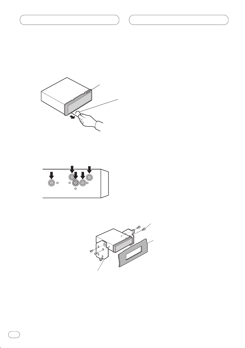
後置視頻輸出
RCA電纜
(附帶)
1.5 m
左(白色)
(REAR VIDEO OUTPUT)
23cm
本產品
RCA電纜
(另售)
至音頻輸入
至視頻輸入
右(紅色)
帶RCA輸入插口
的顯示器
後置音頻輸出
ChH
11
Page 40
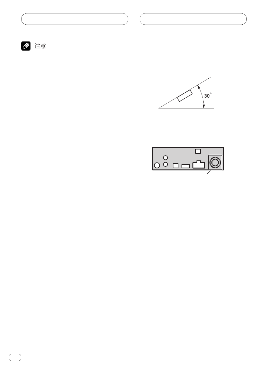
安裝
÷
在本機最終安裝之前,請進行臨時接
線,以確保本機所有連接均已正確且本
÷
如果安裝角度大於水平30。,則本機可
能無法發揮其最佳性能。
系統能正常工作。
÷
請祇用本機附帶的部件,以確保安裝正
確。若使用未經認可的零部件可能會引
起故障。
÷
如果安裝需要打孔或對車輛作其它改
裝,請咨詢您附近的零售商。
÷
請勿將本機安裝在阻擋司機視線的位
置,也不要將本機安裝在車輛突然停止
÷
下圖所示的网罩部位不可遮罩。因為這
是功放器具有良好散熱所需。
(如急煞車)時會使乘客碰傷的位置。
÷
半導體鐳射部件如果過熱會損壞,所以
請勿將本機安裝在高熱的地方,如暖氣
排放口附近。
不要覆蓋該區域
DIN 前面安裝後面安裝
本機可以從“前面”(通常的DIN前面安裝)或“後面”(DIN後面安裝,使用機殼側面的
攻絲螺絲孔)進行安裝。欲知詳情,參閱下述安裝方法。
12
ChH
Page 41

安裝
DIN 前面安裝
使用橡膠襯套安裝
汽車儀表板
移走本機
支座
將底座插入儀表板後,根據儀表板材質的厚
度選擇合適的薄片並將其彎折。(使用頂端
薄片和底端薄片盡可能的安裝牢固。為保証
182
53
安裝牢固,請將薄片彎折到90。)
橡膠襯套
螺絲
面框
將釋放銷釘插入面框底部的孔
內,然後將面框向外拉出。
(重新安裝面框時,將帶有凹
槽的那側對著下方裝上。)
將附帶的抽取鑰匙插入本機,
如圖所示,直到完全插入。將
鑰匙壓向本機,取出機器。
ChH
13
Page 42

安裝
DIN後面安裝
使用本機側面的螺絲孔進行安裝
1 卸下面框。
面框
2 將本機固定於收音機安裝配套支架上。
將釋放銷釘插入面框底部
的孔內,然後將面框向外
拉出。(重新安裝面框
時,把帶有凹槽的那側對
著下方裝上。)
14
ChH
收音機安裝配套支架
將支架的螺絲孔和本機的螺絲孔對準(完
全吻合),且每側有兩處位置用螺絲緊。
根據支架上螺絲孔的形狀,選擇圓頭螺絲
(5×8mm)或平頭螺絲(5×9mm)。
螺絲
儀表板或操作台
Page 43

安裝
固定前面板
如果不使用分離和更換前面板功能,請使用附帶的固定螺絲和支座將前面板固定在本機
上。
1 將支座裝接於前面板的兩側。
支座
2 將前面板放回本機。
3 將支座翻至垂直位置。
4 使用固定螺絲將前面板固定在本機上。
固定螺絲
ChH
15
Page 44

Published by Pioneer Corporation.
Copyright © 2003 by Pioneer Corporation.
All rights reserved.
Publication de Pioneer Corporation.
Copyright © 2003 Pioneer Corporation.
Tous droits de reproduction et de traduction
réservés.
Printed in Japan
Imprimé au Japon
<CRD3793-A> RC, RD<KSNNF/03C00001>
PIONEER CORPORATION
4-1, MEGURO 1-CHOME, MEGURO-KU, TOKYO 153-8654, JAPAN
PIONEER ELECTRONICS (USA) INC.
P.O. Box 1540, Long Beach, California 90801-1540, U.S.A.
TEL: (800) 421-1404
PIONEER EUROPE NV
Haven 1087, Keetberglaan 1, B-9120 Melsele, Belgium
TEL: (0) 3/570.05.11
PIONEER ELECTRONICS ASIACENTRE PTE. LTD.
253 Alexandra Road, #04-01, Singapore 159936
TEL: 65-472-1111
PIONEER ELECTRONICS AUSTRALIA PTY. LTD.
178-184 Boundary Road, Braeside, Victoria 3195, Australia
TEL: (03) 9586-6300
PIONEER ELECTRONICS OF CANADA, INC.
300 Allstate Parkway, Markham, Ontario L3R OP2, Canada
TEL: (905) 479-4411
PIONEER ELECTRONICS DE MEXICO, S.A. de C.V.
Blvd. Manuel Avila Camacho 138 10 piso
Col.Lomas de Chapultepec, Mexico, D.F. 11000
TEL: 55-9178-4270
 Loading...