


DEH-X8600BT

CD RDS RECEIVER
AUTORADIO CD RDS
SINTOLETTORE CD RDS
REPRODUCTOR DE CD CON RECEPTOR RDS
CD RDS-EMPFÄNGER
CD RDS-ONTVANGER
CD RDS ПРИЕМНИК
DEH-X9600BT
DEH-X8600BT
English NederlandsDeutschEspañolItalianoFrançais Русский
Installation Manual
Manuel d’installation
Manuale d’installazione
Manual de instalación
Installationsanleitung
Installatiehandleiding
Руководство по установке
5cmcm
Section
01
Installation
Installation
Important
! Check all connections and systems before
final installation.
! Do not use unauthorized parts as this may
cause malfunctions.
! Consult your dealer if installation requires
drilling of holes or other modifications to the
vehicle.
! Do not install this unit where:
— it may interfere with operation of the vehicle.
— it may cause injury to a passenger as a result
of a sudden stop.
! The semiconductor laser will be damaged if
it overheats. Install this unit away from hot
places such as near the heater outlet.
! Optimum performance is obtained when the
unit is installed at an angle of less than 60°.
60°
! When installing, to ensure proper heat dis-
persal when using this unit, make sure you
leave ample space behind the rear panel and
wrap any loose cables so they are not blocking the vents.
Leave ample
5 cm
space
5 cm
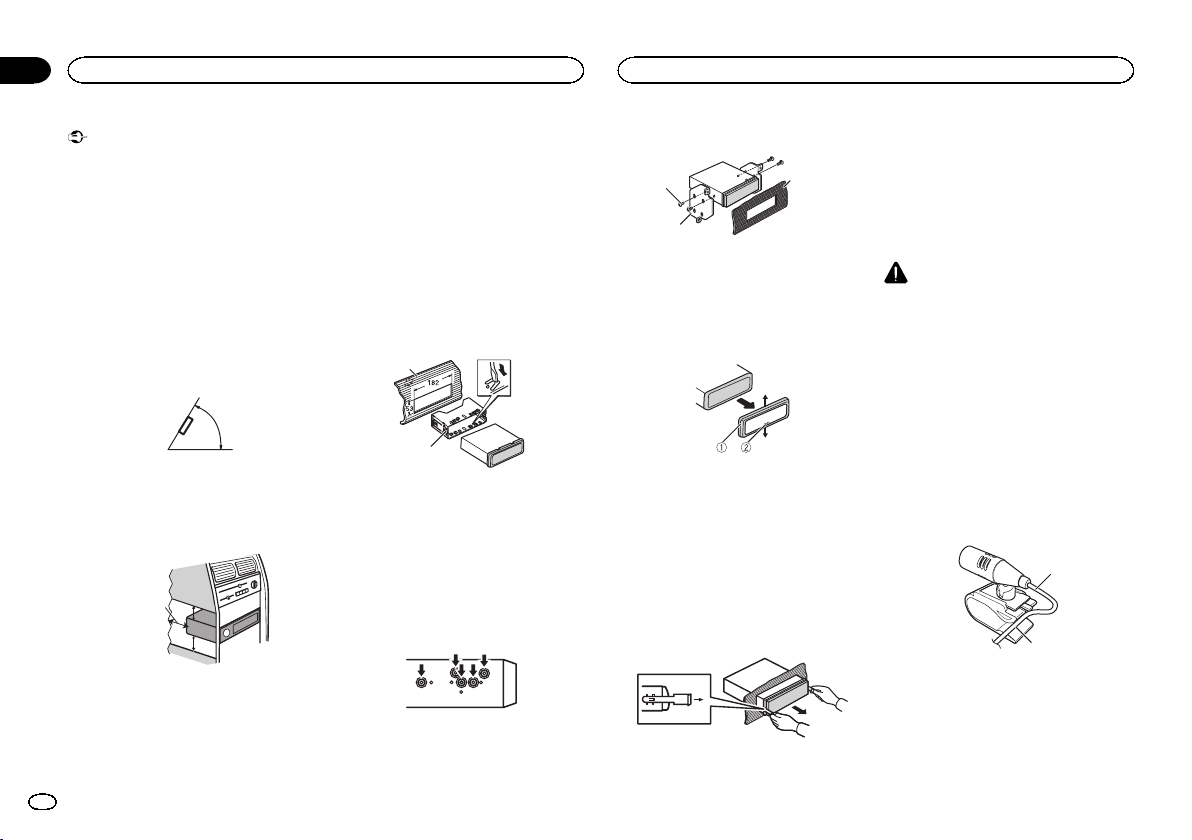
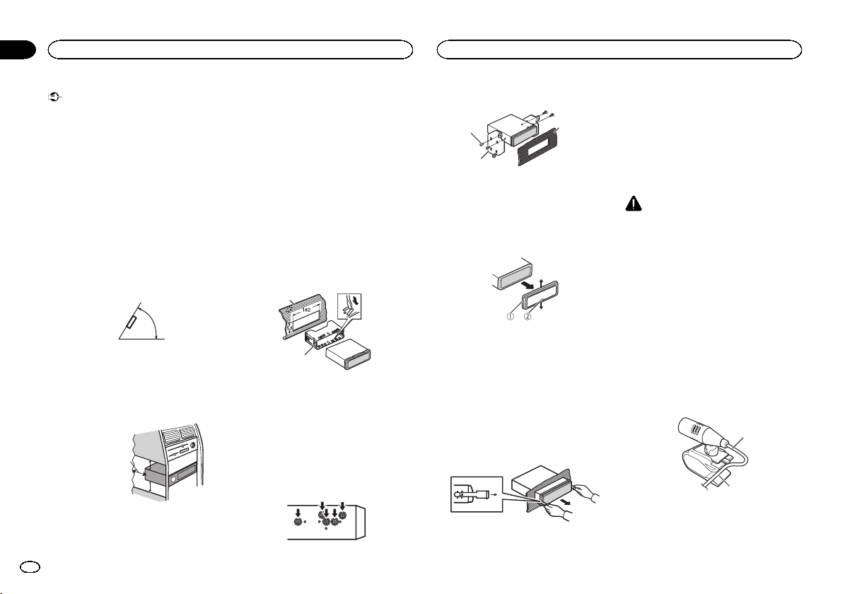
DIN front/rear mount
This unit can be properly installed using either
front-mount or rear-mount installation.
Use commercially available parts when installing.
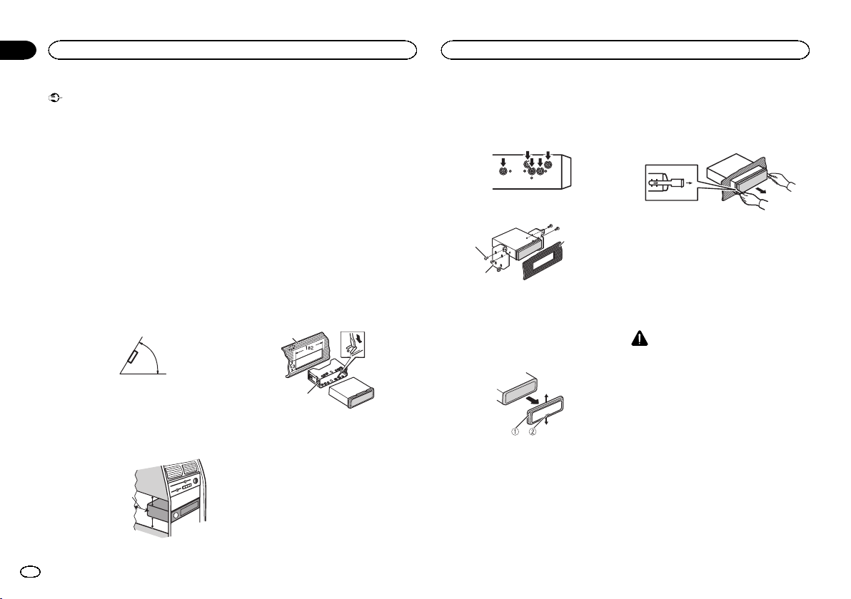
DIN Front-mount
1 Insert the mounting sleeve into the dashboard.
For installation in shallow spaces, use the supplied mounting sleeve. If there is enough space,
use the mounting sleeve that came with the vehicle.
2 Secure the mounting sleeve by using a
screwdriver to bend the metal tabs (90°) into
place.
1
2
1 Dashboard
2 Mounting sleeve
# Make sure that the unit is installed securely in
place. An unstable installation may cause skipping
or other malfunctions.
DIN Rear-mount
1 Determine the appropriate position
where the holes on the bracket and the side
of the unit match.
2 Tighten two screws on each side.
1
2
1 Tapping screw (5 mm × 8 mm)
2 Mounting bracket
3 Dashboard or console
3
Removing the unit
1 Remove the trim ring.
1 Trim ring
2 Notched tab
! Releasing the front panel allows easier ac-
cess to the trim ring.
! When reattaching the trim ring, point the
side with the notched tab down.
2 Insert the supplied extraction keys into
both sides of the unit until they click into
place.
3 Pull the unit out of the dashboard.
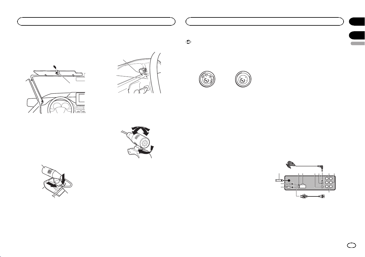
Removing and re-attaching the
front panel
You can remove the front panel to protect your
unit from theft.
For details, refer to operation manual.
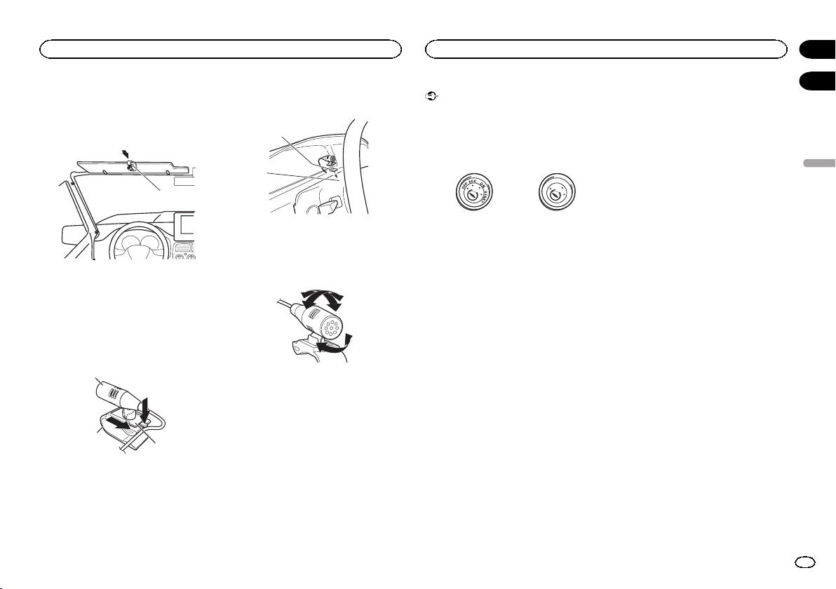
Installing the microphone
CAUTION
It is extremely dangerous to allow the microphone lead to become wound around the steering column or shift lever. Be sure to install the
unit in such a way that it will not obstruct driving.
Notes
! Install the microphone in a position and ori-
entation that will enable it to pick up the
voice of the person operating the system.
! Use separately sold clamps to secure the
lead where necessary inside the vehicle.
When installing the microphone
on the sun visor
1 Fit the microphone lead into the groove.
1
2
1 Microphone lead
2 Groove
2
En
Installation
Connections
Section
01
2 Install the microphone clip on the sun
visor.
With the sun visor up, install the microphone
clip. (Lowering the sun visor reduces the voice
recognition rate.)
1
1 Microphone clip
When installing the microphone
on the steering column
1 Detach the microphone base from the microphone clip.
To detach the microphone base from the microphone clip, slide the microphone base.
1
2
1 Microphone
2 Microphone clip
3 Microphone base
3
2 Install the microphone on the steering
column.
1
2
1 Double-sided tape
2 Install the microphone on therear side of the
steering column.
Adjusting the microphone angle
Important
! When installing this unit in a vehicle without
an ACC (accessory) position on the ignition
switch, failure to connect the red cable to the
terminal that detects operation of the ignition
key may result in battery drain.
O
F
N
F
O
S
T
A
R
T
ACC position No ACC position
! Use of this unit in conditions other than the
following could result in fire or malfunction.
— Vehicles with a 12-volt battery and negative
grounding.
— Speakers with 50 W (output value) and 4 W to
8 W (impedance value).
! To prevent a short-circuit, overheating or mal-
function, be sure to follow the directions
below.
— Disconnect the negative terminal of the bat-
tery before installation.
— Secure the wiring with cable clamps or adhe-
sive tape. Wrap adhesive tape around wiring
that comes into contact with metal parts to
protect the wiring.
— Place all cables away from moving parts,
such as the shift lever and seat rails.
— Place all cables away from hot places, such
as near the heater outlet.
— Do not connect the yellow cable to the battery
by passing it through the hole to the engine
compartment.
— Cover any disconnected cable connectors
with insulating tape.
— Do not shorten any cables.
— Never cut the insulation of the power cable of
this unit in order to share the power with
other devices. The current capacity of the
cable is limited.
— Use a fuse of the rating prescribed.
— Never wire the negative speaker cable directly
to ground.
— Never band together negative cables of multi-
ple speakers.
! When this unit is on, control signals are sent
through the blue/white cable. Connect this
cable to the system remote control of an external power amp or the vehicle’s auto-antenna relay control terminal (max. 300 mA
12 V DC). If the vehicle is equipped with a
glass antenna, connect it to the antenna
booster power supply terminal.
! Never connect the blue/white cable to the
power terminal of an external power amp.
Also, never connect it to the power terminal
of the auto antenna. Doing so may result in
battery drain or a malfunction.
! The black cable is ground. Ground cables for
this unit and other equipment (especially,
high-current products such as power amps)
must be wired separately. If they are not, an
accidental detachment may result in a fire or
malfunction.
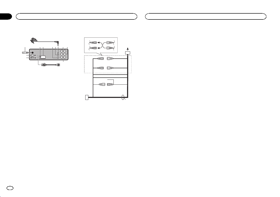
This unit
8
3 4 596 a
2
1
1 USB port 1
2 USB port 2 (DEH-X9600BT only)
3 Antenna input 15 cm
4 Fuse (10 A)
5 Power cord input
6 Wired remote input
Hard-wired remote control adapter can be
connected (sold separately).
7
c
b
02
English
3
En
d
Section
02
Connections
Connections
7 Microphone input
8 Microphone (4 m)
9 Rear output
a Front output
b Subwoofer output
c USB cable 1.5 m
! If connecting both USB1/iPod1 and
USB2/iPod2 at the same time, use a
Pioneer USB cable (CD-U50E) in addition
to the regular Pioneer USB cable.
Power cord
3
4
1
3
556
a
6
4
c
b
2
7
8
9
e
1 To power cord input
2 Depending on the kind of vehicle, the func-
tion of 3 and 5 may be different. In this
case, be sure to connect 4 to 5 and 6 to
3.
3 Yellow
Back-up (or accessory)
4 Yellow
Connect to the constant 12 V supply terminal.
5 Red
Accessory (or back-up)
6 Red
Connect to terminal controlled by ignition
switch (12 V DC).
7 Connect leads of the same color to each
other.
8 Orange/white
Connect to lighting switch terminal.
9 Black (chassis ground)
a Blue/white
The pin position of the ISO connector will differ depending on the type of vehicle. Connect
a and b when Pin 5 is an antenna control
type. In another type of vehicle, never connect a and b.
b Blue/white
Connect to system control terminal of the
power amp (max. 300 mA 12 V DC).
c Blue/white
Connect to auto-antenna relay control terminal (max. 300 mA 12 V DC).
d Speaker leads
White: Front left +
White/black: Front left *
Gray: Front right +
Gray/black: Front right *
Green: Rear left + or subwoofer +
Green/black: Rear left * or subwoofer *
Violet: Rear right + or subwoofer +
Violet/black: Rear right * or subwoofer *
e ISO connector
In some vehicles, the ISO connector may be
divided into two. In this case, be sure to connect to both connectors.
Notes
! Change the set up menu of this unit (refer to
the operation manual). The subwoofer output
of this unit is monaural.
! When using a subwoofer of 70 W (2 W ), be
sure to connect the subwoofer to the violet
and violet/black leads of this unit. Do not
connect anything to the green and green/
black leads.
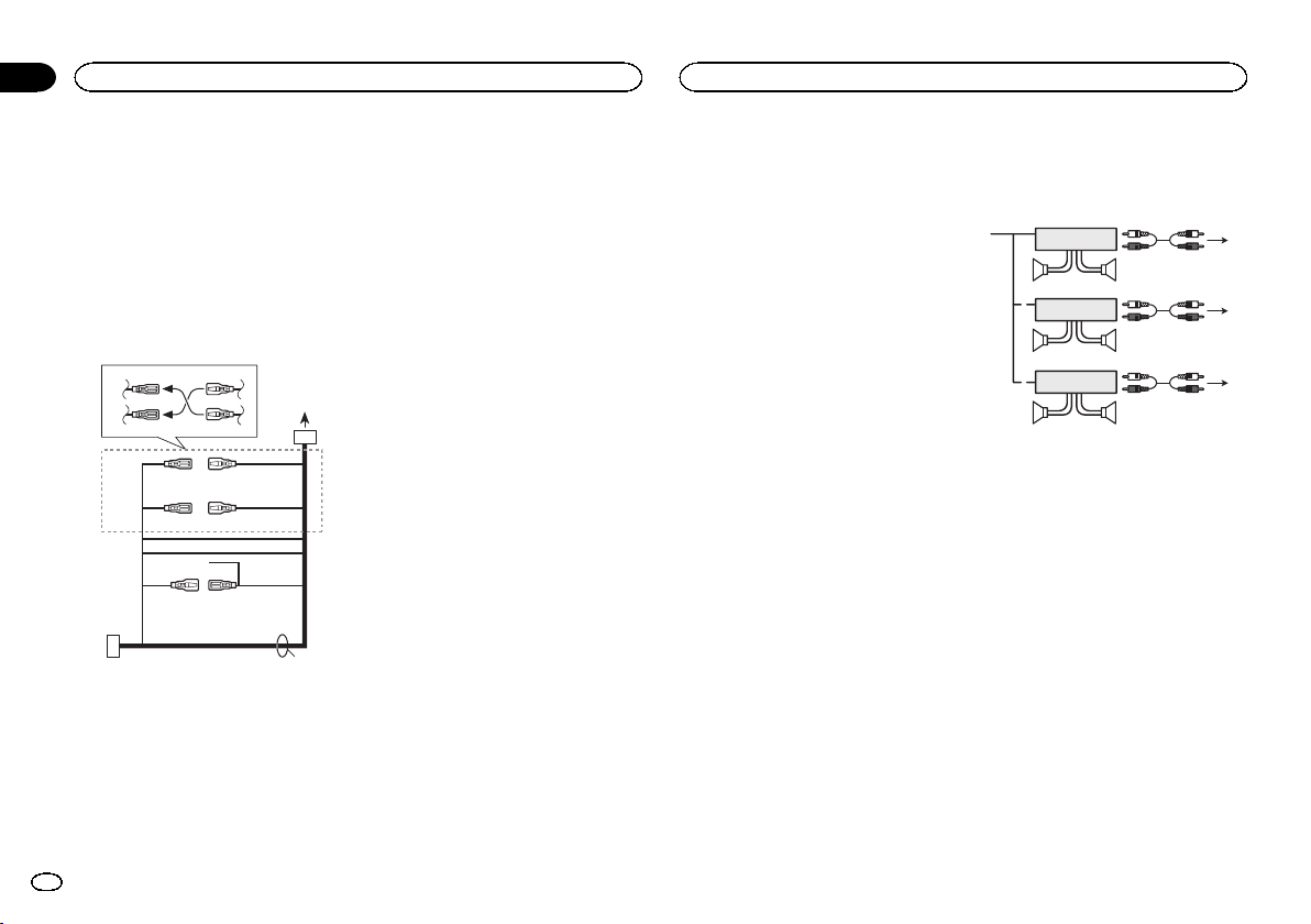
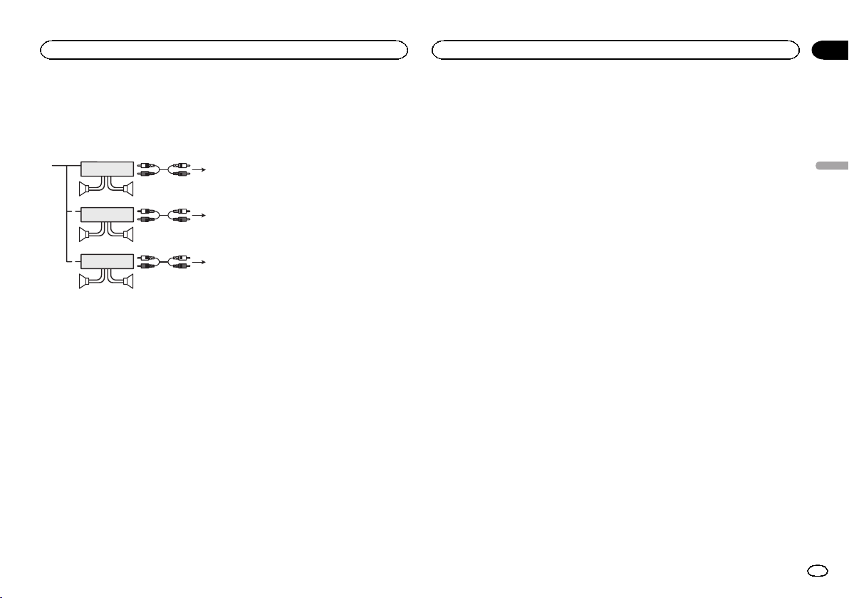
Power amp (sold separately)
Perform these connections when using the optional amplifier.
1
1
1
1 System remote control
Connect to Blue/white cable.
2 Power amp (sold separately)
3 Connect with RCA cable (sold separately)
4 To Rear output
5 Rear speaker
6 To Front output
7 Front speaker
8 To subwoofer output
9 Subwoofer
3
2
55
3
2
77
3
2
99
4
6
8
4
En

English
5En
5cmcm
Section
01
Installation
Installation
Important
! Vérifiez toutes les connexions et tous les sys-
tèmes avant l’installation finale.
! N’utilisez pas de pièces non autorisées car il
peut en résulter des dysfonctionnements.
! Consultez votre revendeur si l’installation né-
cessite le perçage de trous ou d’autres modifications du véhicule.
! N’installez pas cet appareil là où :
— il peut interférer avec l’utilisation du véhicule.
— il peut blesser un passager en cas d’arrêt
soudain du véhicule.
! Le laser à semi-conducteur sera endommagé
s’il devient trop chaud. Installez cet appareil
àl’écart de tous les endroits chauds, par
exemple les sorties de chauffage.
! Des performances optimales sont obtenues
quand l’appareil est installé à un angle inférieur à 60°.
60°
! Lors de l’installation, pour assurer une dis-
persion correcte de la chaleur quand cet appareil est utilisé, assurez-vous de laisser un
espace important derrière la face arrière et
enroulez les câbles volants de façon qu’ils ne
bloquent pas les orifices d’aération.
Laissez suffisamment
d’espace
5 cm
5 cm
Montage avant/arrière DIN
Cet appareil peut être installé correctement soit
en montage frontal ou en montage arrière.
Utilisez des pièces disponibles dans le
commerce lors de l’installation.
Montage frontal DIN
1 Insérez le manchon de montage dans le
tableau de bord.
Lors de l’installation de cet appareil dans un espace peu profond, utilisez le manchon de montage fourni. Si l’espace est suffisant, utilisez le
manchon de montage fourni avec le véhicule.
2 Fixez le manchon de montage en utilisant
un tournevis pour courber les pattes métalliques (90°) en place.
1
2
1 Tableau de bord
2 Manchon de montage
# Assurez-vous que l’appareil est correctement mis
en place. Toute installation instable peut entraîner
des sauts ou autres dysfonctionnements.
Montage arrière DIN
1 Déterminez la position appropriée où les
trous sur le support et sur le côté de l’appareil se correspondent.
2 Serrez deux vis de chaque côté.
1
2
1 Vis taraudeuse (5 mm × 8 mm)
2 Support de montage
3 Tableau de bord ou console
3
Retrait de l’appareil
1 Retirez l’anneau de garniture.
1 Anneau de garniture
2 Encoche
! Retirer la face avant permet d’accéder plus
facilement à l’anneau de garniture.
! Quand vous remontez l’anneau de garniture,
pointez le côté avec l’encoche vers le bas.
2 Insérez les clés d’extraction fournies dans
les deux côtés de l’appareil jusqu’àcequ’el-
les s’enclenchent en place.
3 Tirez l’appareil hors du tableau de bord.
Retrait et remontage de la face
avant
Vous pouvez retirer la face avant pour protéger
l’appareil contre le vol.
Pour plus de détails, reportez-vous au mode
d’emploi.
Installation du microphone
PRÉCAUTION
Il est extrêmement dangereux de laisser le fil du
microphone s’enrouler autour de la colonne de
direction ou du levier de vitesse. Assurez-vous
d’installer cet appareil de telle manière qu’il ne
gêne pas la conduite.
Remarques
! Installez le microphone dans une position et
une orientation qui lui permette de capter la
voix de la personne qui utilise le système.
! Utilisez des serre-fils vendus séparément
pour fixer le fil là où c’est nécessaire dans le
véhicule.
Si vous installez le microphone
sur le pare-soleil
1 Insérez le fil du microphone dans la
fente.
1
2
1 Fil du microphone
2 Rainure
6
Fr
Installation
Connexions
Section
01
2 Installez le clip microphone sur le paresoleil.
Avec le pare-soleil relevé, installez le clip microphone. (Abaisser le pare-soleil réduit le taux de
reconnaissance vocale.)
1
1 Clip microphone
Si vous installez le microphone
sur la colonne de direction
1 Détachez la base pour microphone du
clip microphone.
Pour détacher la base pour microphone du clip
microphone, faites-la glisser.
1
2
1 Microphone
2 Clip microphone
3 Base pour microphone
3
2 Installez le microphone sur la colonne de
direction.
1
2
1 Bande double face
2 Installez le microphone sur la face arrière de
la colonne de direction.
Réglage de l’angle du microphone
Important
! Lors de l’installation de cet appareil dans un
véhicule sans position ACC (accessoire) sur
le contact d’allumage, ne pas connecter le
câble rouge à la borne qui détecte l’utilisation de la clé de contact peut entraîner le déchargement de la batterie.
O
F
N
F
O
S
T
A
R
T
Avec position ACC Sans position ACC
! L’utilisation de cet appareil dans des condi-
tions autres que les conditions suivantes
pourrait provoquer un incendie ou un mauvais fonctionnement.
— Véhicules avec une batterie 12 volts et mise à
la masse du négatif.
— Haut-parleurs avec une puissance de sortie
de 50 W et une impédance de 4 W à8W.
! Pour éviter un court-circuit, une surchauffe
ou un dysfonctionnement, assurez-vous de
respecter les instructions suivantes.
— Déconnectez la borne négative de la batterie
avant l’installation.
— Fixez le câblage avec des serre-fils ou de la
bande adhésive. Pour protéger le câblage, enroulez dans du ruban adhésif les parties du
câblage en contact avec des pièces en métal.
— Placez les câbles à l’écart de toutes les par-
ties mobiles, telles que le levier de vitesse et
les rails des sièges.
— Placez les câbles à l’écart de tous les endroits
chauds, par exemple les sorties de chauffage.
— Ne reliez pas le câble jaune à la batterie à tra-
vers le trou dans le compartiment moteur.
— Recouvrez tous les connecteurs de câbles qui
ne sont pas connectés avec du ruban adhésif
isolant.
— Ne raccourcissez pas les câbles.
— Ne coupez jamais l’isolation du câble d’ali-
mentation de cet appareil pour partager l’alimentation avec d’autres appareils. La
capacité en courant du câble est limitée.
— Utilisez un fusible correspondant aux caracté-
ristiques spécifiées.
— Ne câblez jamais le câble négatif du haut-par-
leur directement à la masse.
— Ne réunissez jamais ensemble les câbles né-
gatifs de plusieurs haut-parleurs.
! Lorsque cet appareil est sous tension, les si-
gnaux de commande sont transmis via le
câble bleu/blanc. Connectez ce câble à la télécommande du système d’un amplificateur
de puissance externe ou à la borne de
commande du relais de l’antenne motorisée
du véhicule (max. 300 mA 12 V CC). Si le véhicule est équipé d’une antenne intégrée à la
lunette arrière, connectez-le à la borne d’alimentation de l’amplificateur d’antenne.
! Ne reliez jamais le câble bleu/blanc à la
borne d’alimentation d’un amplificateur de
puissance externe. De même, ne le reliez pas
à la borne d’alimentation de l’antenne motorisée. Dans le cas contraire, il peut en résulter un déchargement de la batterie ou un
dysfonctionnement.
! Le câble noir est la masse. Les câbles de
terre de cet appareil et d’autres produits (particulièrement les produits avec des courants
élevés tels que l’amplificateur de puissance)
doivent être câblés séparément. Dans le cas
contraire, ils peuvent se détacher accidentellement et provoquer un incendie ou un dysfonctionnement.
02
Français
7
Fr
d
Section
02
Connexions
Connexions
Cet appareil
8
3 4 596 a
2
1
1 Port USB 1
2 Port USB 2 (DEH-X9600BT uniquement)
3 Entrée antenne 15 cm
4 Fusible (10 A)
5 Entrée cordon d’alimentation
6 Entrée télécommande câblée
Un adaptateur de télécommande câblée
(vendu séparément) peut être connecté.
7 Entrée microphone
8 Microphone (4 m)
9 Sortie arrière
a Sortie avant
b Sortie haut-parleur d’extrêmes graves
c Câble USB 1,5 m
! Si vous connectez USB1/iPod1 et USB2/
iPod2 simultanément, utilisez un câble
USB Pioneer (CD-U50E) en plus du câble
USB Pioneer standard.
7
c
b
Cordon d’alimentation
3
4
1
3
556
a
6
4
c
b
2
7
8
9
e
1 Vers l’entrée cordon d’alimentation
2 Selon le type de véhicule, 3 et 5 peuvent
avoir une fonction différente. Dans ce cas,
assurez-vous de connecter 4 à 5 et 6 à 3.
3 Jaune
Alimentation de secours (ou accessoire)
4 Jaune
Connectez à la borne d’alimentation 12 V permanente.
5 Rouge
Accessoire (ou alimentation de secours)
6 Rouge
Connectez à la borne contrôlée par le
contact d’allumage (12 V CC).
7 Connectez les fils de même couleur en-
semble.
8 Orange/blanc
Connectez à la borne du commutateur d’éclairage.
9 Noir (masse du châssis)
a Bleu/blanc
La position des broches du connecteur ISO
est différente selon le type de véhicule.
Connectez a et b lorsque la broche 5 est de
type commande de l’antenne. Dans un type
différent de véhicule, ne connectez jamais a
et b.
b Bleu/blanc
Connectez à la borne de commande du système de l’amplificateur de puissance (max.
300 mA 12 V CC).
c Bleu/blanc
Connectez à la borne de commande du relais
de l’antenne motorisée (max. 300 mA 12 V
CC).
d Fils des haut-parleurs
Blanc : Avant gauche +
Blanc/noir : Avant gauche *
Gris : Avant droite +
Gris/noir : Avant droite *
Vert: Arrière gauche + ou haut-parleur d’extrêmes graves +
Vert/noir: Arrière gauche * ou haut-parleur
d’extrêmes graves *
Violet : Arrière droite + ou haut-parleur d’extrêmes graves +
Violet/noir: Arrière droite * ou haut-parleur
d’extrêmes graves *
e Connecteur ISO
Dans certains véhicules, il est possible que
le connecteur ISO soit divisé en deux. Dans
ce cas, assurez-vous de connecter les deux
connecteurs.
Remarques
! Changez le menu de configuration de cet ap-
pareil (reportez-vous au mode d’emploi). La
sortie haut-parleur d’extrêmes graves de cet
appareil est monaurale.
! Lors de l’utilisation d’un haut-parleur d’extrê-
mes graves de 70 W (2 W), assurez-vous de
connecter le haut-parleur d’extrêmes graves
aux fils violet et violet/noir de cet appareil. Ne
connectez aucun périphérique aux fils vert et
vert/noir.
8
Fr
Connexions
Amplificateur de puissance
(vendu séparément)
Réalisez ces connexions lors de l’utilisation d’un
amplificateur optionnel.
1
1
1
1 Télécommande du système
Connectez au câble bleu/blanc.
2 Amplificateur de puissance (vendu séparé-
ment)
3 Connectez avec un câble RCA (vendu séparé-
ment)
4 Vers la sortie arrière
5 Haut-parleur arrière
6 Vers la sortie avant
7 Haut-parleur avant
8 Vers la sortie haut-parleur d’extrêmes graves
9 Haut-parleur d’extrêmes graves
3
2
55
3
2
77
3
2
99
4
6
8
Section
02
Français
9
Fr
5cmcm
Sezione
01
Installazione
Installazione
Importante
! Controllare tutti i collegamenti e i sistemi
prima dell’installazione finale.
! Non utilizzare componenti non approvati,
poiché potrebbero provocare malfunzionamenti.
! Consultare il rivenditore se l’installazione ri-
chiede la trapanatura di fori o altre modifiche
del veicolo.
! Non installare questa unità se:
— potrebbe interferire con il funzionamento del
veicolo.
— potrebbe procurare lesioni al passeggero in
caso di arresto improvviso del veicolo.
! Se si surriscalda il laser a semiconduttore
potrebbe subire danni. Non installare questa
unità in luoghi soggetti a surriscaldamento,
come in prossimità delle bocchette dell’impianto di riscaldamento.
! Le prestazioni ottimali si ottengono quando
l’unità viene installata con un’angolazione inferiore a 60°.
60°
! Durante l’installazione, per assicurare la cor-
retta dissipazione del calore quando si utilizza l’unità, accertarsi di lasciare ampio spazio
dietro il pannello posteriore e avvolgere eventuali cavi allentati in modo che non ostruiscano le aperture.
Lasciare ampio spazio
5 cm
5 cm
Montaggio DIN anteriore/
posteriore
Questa unità può essere installata correttamente sia dalla posizione di montaggio anteriore, sia
dalla posizione di montaggio posteriore.
Durante l’installazione utilizzare componenti disponibili in commercio.
Montaggio DIN anteriore
1 Inserire la fascetta di montaggio nel cruscotto.
Se l’unità viene installata in uno spazio poco
profondo, utilizzare la fascetta di montaggio fornita. Se dietro l’unità vi è spazio sufficiente, utilizzare la fascetta di montaggio fornita con il
veicolo.
2 Assicurare la fascetta di montaggio utilizzando un cacciavite per piegare le linguette
metalliche (90°) in posizione.
1
2
1 Cruscotto
2 Fascetta di montaggio
# Accertarsi che l’unità sia saldamente installata
in posizione. Un’installazione instabile potrebbe causare salti audio o altri malfunzionamenti.
Montaggio DIN posteriore
1 Determinare la posizione appropriata, in
modo che i fori sulla staffa e sul lato dell’unità corrispondano.
2 Serrare due viti su ciascun lato.
1
2
1 Vite autofilettante (5 mm × 8 mm)
2 Staffa di montaggio
3 Cruscotto o console
3
Rimozione dell’unità
1 Rimuovere la guarnizione.
1 Guarnizione
2 Linguetta intaccata
! La rimozione del frontalino permette di acce-
dere facilmente alla guarnizione.
! Quando si riapplica la guarnizione, spingere
il lato con la linguetta intaccata verso il
basso.
2 Inserire le chiavi di estrazione fornite su
entrambi i lati dell’unità fino a che non scattano in posizione.
3 Estrarre l’unità dal cruscotto.
Rimozione e reinserimento del
frontalino
È possibile rimuovere il frontalino per proteggere l’unità dai furti.
Per ulteriori dettagli, vedere il manuale d’istruzioni.
Installazione del microfono
ATTENZIONE
È estremamente pericoloso se il filo di sostegno
del microfono si avvolge attorno al piantone
dello sterzo o alla leva del cambio. Accertarsi
quindi di installare questa unità in modo tale da
non ostacolare la guida.
Note
! Installare il microfono in una posizione e un
orientamento tale da consentire il rilevamento della voce della persona che utilizza il sistema.
! Utilizzare i morsetti venduti separatamente
per assicurare il cavo, ove necessario, all’interno del veicolo.
10
It
 Loading...