

PIONEER DEH-P650, DEH-P6500, DEH-P6550 Service Manual
PIONEER CORPORATION 4-1, Meguro 1-Chome, Meguro-ku, Tokyo 153-8654, Japan
PIONEER ELECTRONICS (USA) INC. P.O.Box 1760, Long Beach, CA 90801-1760 U.S.A.
PIONEER EUROPE NV Haven 1087 Keetberglaan 1, 9120 Melsele, Belgium
PIONEER ELECTRONICS ASIACENTRE PTE.LTD. 253 Alexandra Road, #04-01, Singapore 159936
C PIONEER CORPORATION 2002
K-ZZS. DEC. 2002 Printed in Japan
ORDER NO.
CRT3011
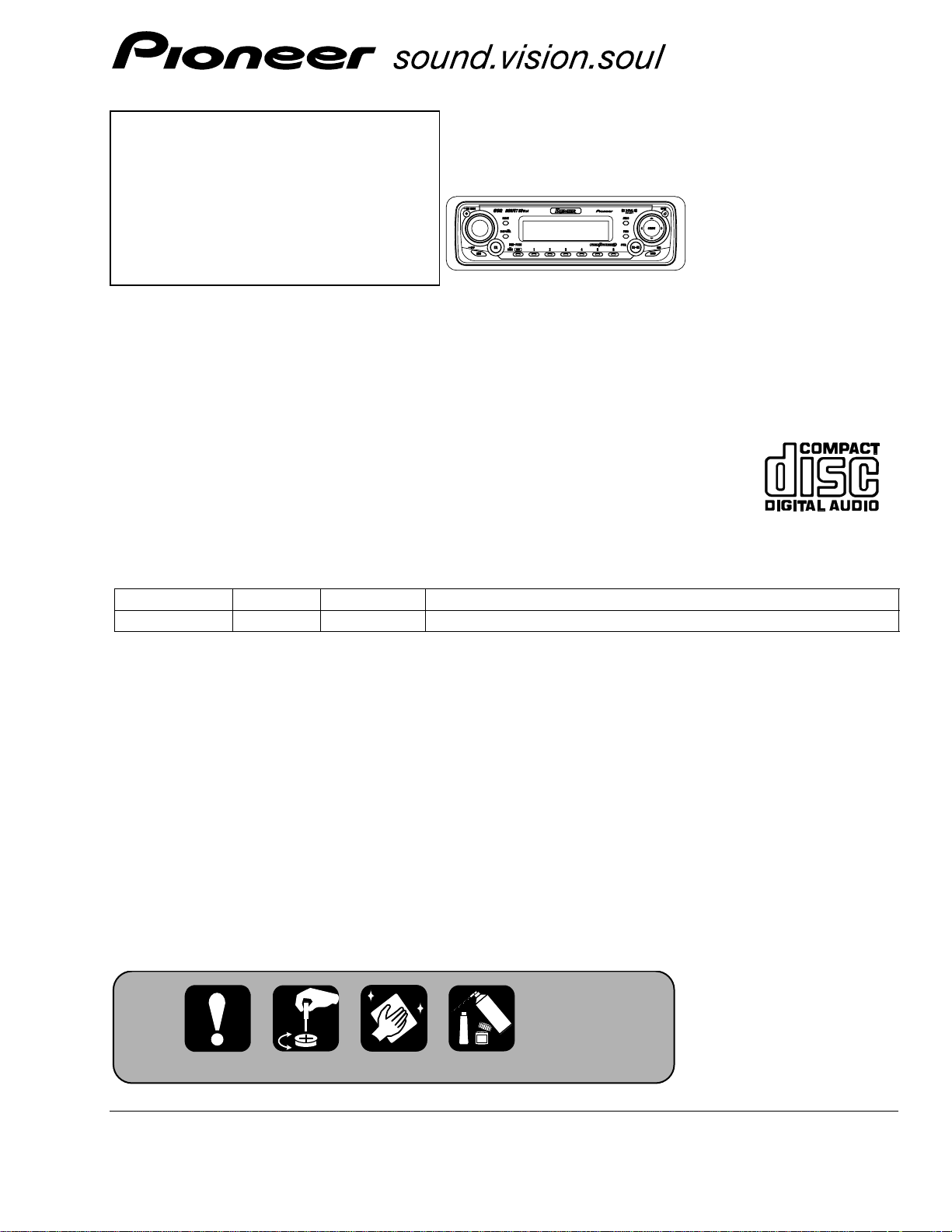
MULTI-CD CONTROL HIGH POWER CD PLAYER WITH FM/AM TUNER
DEH-P650XN/UC
DEH-P650/XN/UC
DEH-P6500XN/UC
For details, refer to "Important symbols for good services".
- This service manual should be used together with the following manual(s):
Model No. Order No. Mech. Module Remarks
CX-3026 CRT2944 S10
CD Mech. Module:Circuit Description, Mech.Description, Disassembly
DEH-P6550
XN/ES
2
1
234
12
34
F
E
D
C
B
A
DEH-P650/XN/UC
[ Important symbols for good services ]
In this manual, the symbols shown-below indicate that adjustments, settings or cleaning should be made securely.
When you find the procedures bearing any of the symbols, be sure to fulfill them:
2. Adjustments
To keep the original performances of the product, optimum adjustments or specification confirmation is indispensable.
In accordance with the procedures or instructions described in this manual, adjustments should be performed.
3. Cleaning
For optical pickups, tape-deck heads, lenses and mirrors used in projection monitors, and other parts requiring cleaning,
proper cleaning should be performed to restore their performances.
5. Lubricants, glues, and replacement parts
Appropriately applying grease or glue can maintain the product performances. But improper lubrication or applying
glue may lead to failures or troubles in the product. By following the instructions in this manual, be sure to apply the
prescribed grease or glue to proper portions by the appropriate amount.For replacement parts or tools, the prescribed
ones should be used.
4. Shipping mode and shipping screws
To protect the product from damages or failures that may be caused during transit, the shipping mode should be set or
the shipping screws should be installed before shipping out in accordance with this manual, if necessary.
1. Product safety
You should conform to the regulations governing the product (safety, radio and noise, and other regulations), and
should keep the safety during servicing by following the safety instructions described in this manual.
SAFETY INFORMATION
- CD section precaution
1. Before disassembling the unit, be sure to turn off
the power. Unplugging and plugging the connectors
during power-on mode may damage the ICs inside
the unit.
2. To protect the pickup unit from electrostatic discharge
during servicing, take an appropriate treatment
(shorting-solder) by referring to "the DISASSEMBLY"
on page 58.
3. After replacing the pickup unit, be sure to check the
grating. (See p.54.)
CAUTION
This service manual is intended for qualified service technicians; it is not meant for the casual do-it-yourselfer.
Qualified technicians have the necessary test equipment and tools, and have been trained to properly and safely repair
complex products such as those covered by this manual.
Improperly performed repairs can adversely affect the safety and reliability of the product and may void the warranty.
If you are not qualified to perform the repair of this product properly and safely, you should not risk trying to do so
and refer the repair to a qualified service technician.
W
ARNING
This product contains lead in solder and certain electrical parts contain chemicals which are known to the state of
California to cause cancer, birth defects or other reproductive harm.
Health & Safety Code Section 25249.6 - Proposition 65

3
5
6
7
8
F
E
D
C
B
A
5
6
7
8
DEH-P650/XN/UC
CONTENTS
SAFETY INFORMATION........................................................................................................................................2
1. SPECIFICATIONS...............................................................................................................................................4
2. EXPLODED VIEWS AND PARTS LIST ..............................................................................................................6
2.1 PACKING(DEH-P650/XN/UC) ......................................................................................................................6
2.2 PACKING(DEH-P6500/XN/UC, P6550/XN/ES)............................................................................................8
2.3 EXTERIOR(DEH-P650/XN/UC) ..................................................................................................................10
2.4 EXTERIOR(DEH-P6500/XN/UC, P6550/XN/ES) ........................................................................................12
2.5 CD MECHANISM MODULE ......................................................................................................................14
3. BLOCK DIAGRAM AND SCHEMATIC DIAGRAM ..........................................................................................16
3.1 BLOCK DIAGRAM......................................................................................................................................16
3.2 OVERALL CONNECTION DIAGRAM(DEH-P650/XN/UC, P6500/XN/UC) ...............................................18
3.3 OVERALL CONNECTION DIAGRAM(DEH-P650/XN/UC) ........................................................................24
3.4 KEYBOARD UNIT ......................................................................................................................................30
3.5 CD MECHANISM MODULE ......................................................................................................................32
4. PCB CONNECTION DIAGRAM .......................................................................................................................36
4.1 TUNER AMP UNIT.....................................................................................................................................36
4.2 KEYBOARD UNIT .....................................................................................................................................40
4.3 PANEL UNIT...............................................................................................................................................41
4.4 CD MECHANISM MODULE ......................................................................................................................42
5. ELECTRICAL PARTS LIST................................................................................................................................44
6. ADJUSTMENT .................................................................................................................................................52
6.1 CD ADJUSTMENT.....................................................................................................................................52
6.2 CHECKING THE GRATING AFTER CHANGING THE PICKUP UNIT .......................................................54
6.3 ERROR MODE............................................................................................................................................56
6.4 OEL UNIT ADJUSTMENT .........................................................................................................................57
7. GENERAL INFORMATION...............................................................................................................................58
7.1 DIAGNOSIS................................................................................................................................................58
7.1.1 DISASSEMBLY....................................................................................................................................58
7.1.2
CONNECTOR FUNCTION DESCRIPTION .............................................................................................60
7.2 IC.................................................................................................................................................................61
7.3 OPERATIONAL FLOW CHART ..................................................................................................................70
7.4 CLEANING .................................................................................................................................................71
8. OPERATIONS ..................................................................................................................................................72
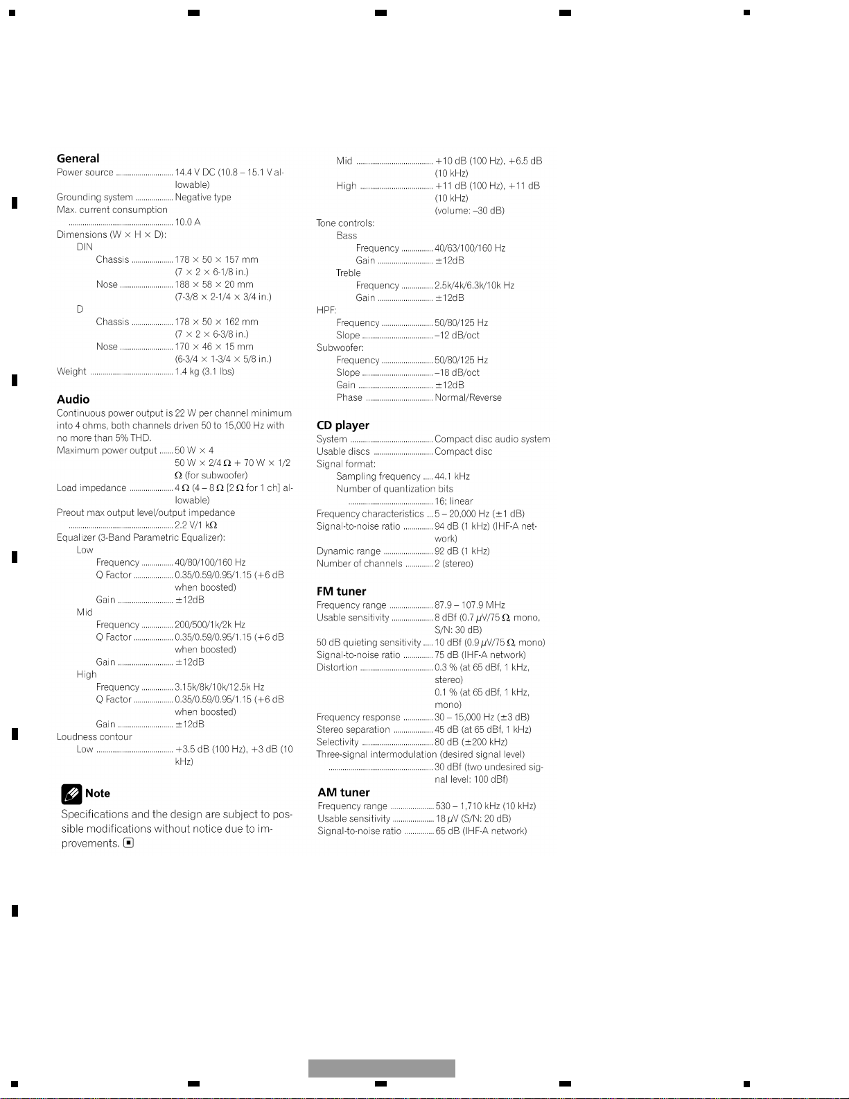
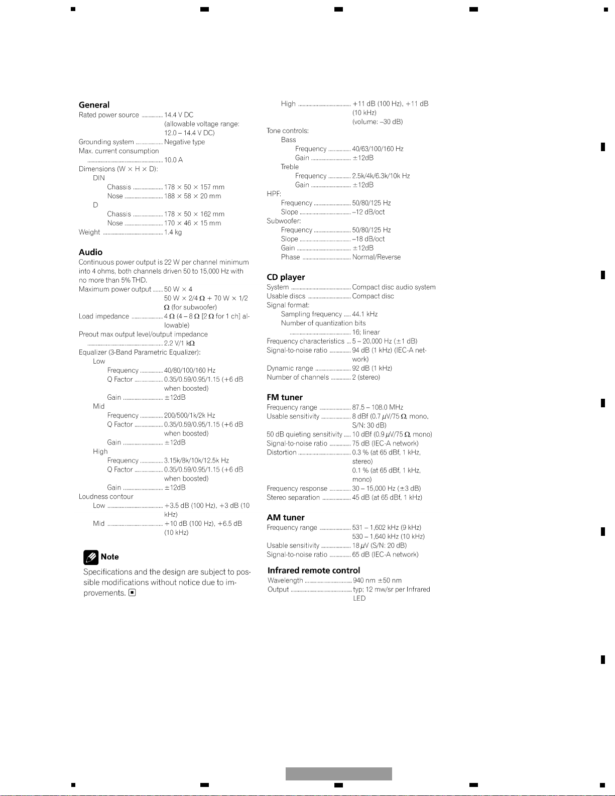
1. SPECIFICATIONS
4
1
234
12
34
F
E
D
C
B
A
DEH-P650/XN/UC
- DEH-P650/XN/UC, P6500/XN/UC
Backup current.................... 5 mA or less
5
5
6
7
8
F
E
D
C
B
A
5
6
7
8
DEH-P650/XN/UC
Backup current....................5 mA or less
- DEH-P6550/XN/ES
6
1
234
12
34
F
E
D
C
B
A
DEH-P650/XN/UC
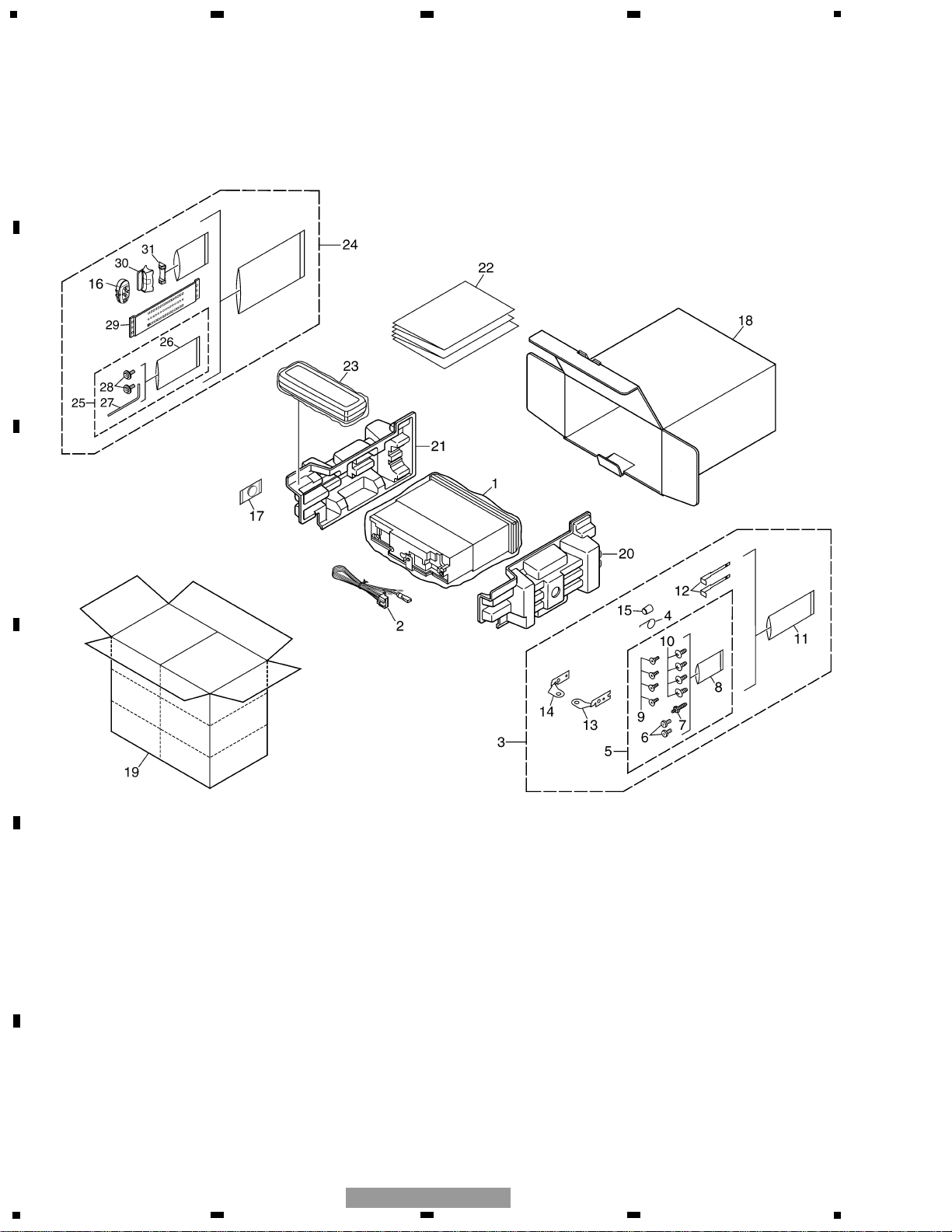
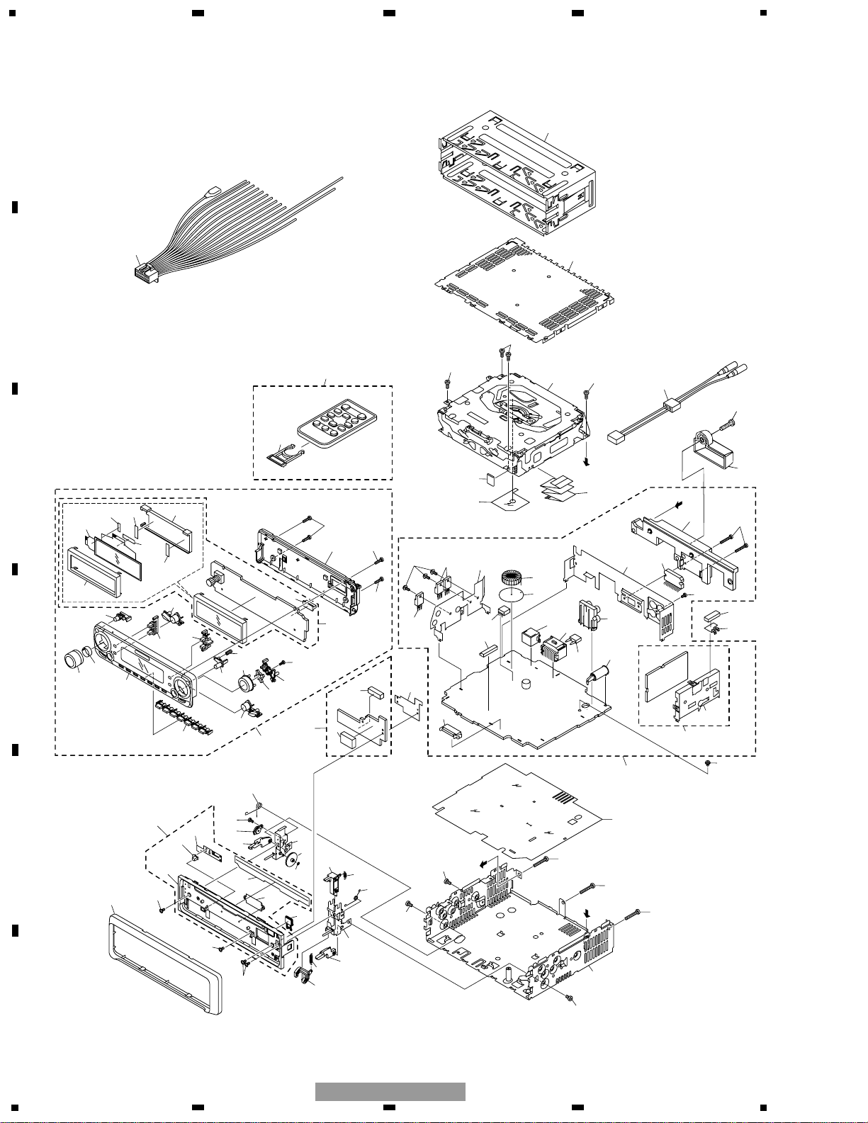
2. EXPLODED VIEWS AND PARTS LIST
2.1 PACKING(DEH-P650/XN/UC)

7
5
6
7
8
F
E
D
C
B
A
5
6
7
8
DEH-P650/XN/UC
1 Polyethylene Bag CEG1173
2 Cord Assy CDE7154
3 Accessory Assy CEA3376
4 Spring CBH1650
5 Screw Assy CEA3445
6 Fixing Screw BPZ20P060FZK
7 Screw CBA1002
* 8 Polyethylene Bag CEG-127
9 Screw CRZ50P090FTC
10 Screw TRZ50P080FTC
* 11 Polyethylene Bag CEG-158
12 Handle CNC5395
13 Holder CND1249
14 Holder CND1250
15 Bush CNV3930
16 Remote Control Assy CZX3257
* 17 Battery CEX1030
18 Carton CHG4947
19 Contain Box CHL4947
20 Protector CHP2663
21 Protector CHP2664
22-1 Owner’s Manual CRD3708
(English, Spanish)
22-2 Installation Manual CRD3709
(English, Spanish)
* 22-3 Warranty Card CRY1070
* 22-4 Caution Card CRP1207
23 Case Assy CXB3520
24 Remote Control Assy CXB9202
25 Screw Assy CZE3169
* 26 Polyethylene Bag CEG-127
* 27 Hexagonal Wrench CZE3176
* 28 Screw RMZ30H060FBK
29 Belt CZN7661
30 Holder Assy CZX3172
31 Holder Assy CZX3173
Mark No. Description Part No. Mark No. Description Part No.
- PACKING(DEH-P650/XN/UC) SECTION PARTS LIST
NOTE:
- Parts marked by “*” are generally unavailable because they are not in our Master Spare Parts List.
- Screws adjacent to ∇ mark on the product are used for disassembly.
- For the applying amount of lubricants or glue, follow the instructions in this manual.
( In the case of no amount instructions, apply as you think it appropriate.)
8
1
234
12
34
F
E
D
C
B
A
DEH-P650/XN/UC
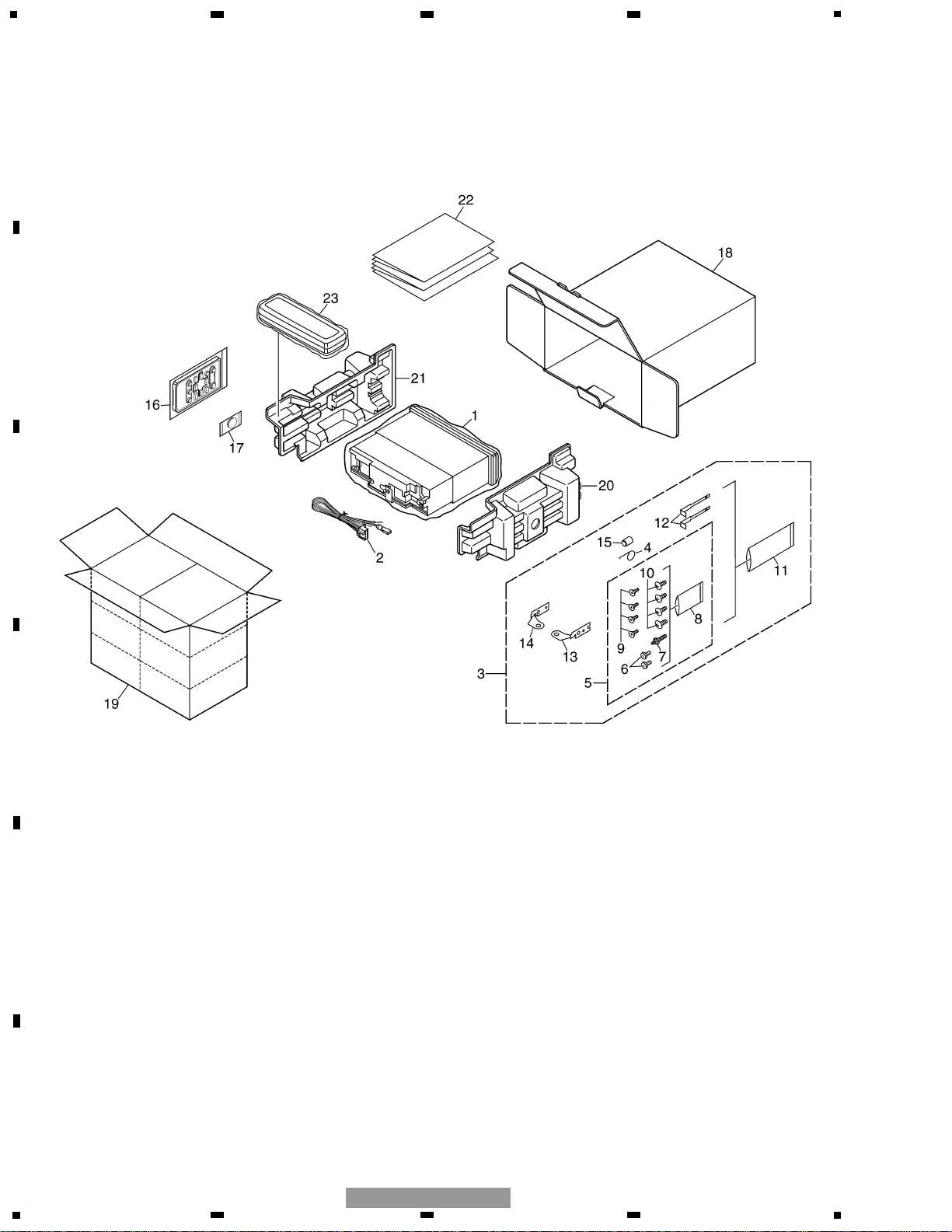
2.2 PACKING(DEH-P6500/XN/UC, P6550/XN/ES)
9
5
6
7
8
F
E
D
C
B
A
5
6
7
8
DEH-P650/XN/UC
1 Polyethylene Bag See Contrast table(2)
2 Cord Assy CDE7154
3 Accessory Assy
See Contrast table(2)
4 Spring CBH1650
5 Screw Assy
See Contrast table(2)
6 Fixing Screw
See Contrast table(2)
7 Screw CBA1002
* 8 Polyethylene Bag CEG-127
9 Screw CRZ50P090FTC
10 Screw TRZ50P080FTC
* 11 Polyethylene Bag CEG-158
12 Handle CNC5395
13 Holder
See Contrast table(2)
14 Holder See Contrast table(2)
15 Bush CNV3930
16 Remote Control Unit CXC1265
* 17 Battery CEX1065
18 Carton
See Contrast table(2)
19 Contain Box See Contrast table(2)
20 Protector CHP2663
21 Protector CHP2664
22-1 Owner’s Manual
See Contrast table(2)
22-2 Installation Manual See Contrast table(2)
* 22-3 Caution Card See Contrast table(2)
* 22-4 Card
See Contrast table(2)
22-5 Owner’s Manual
See Contrast table(2)
* 22-6 Caution Card CRP1207
23 Case Assy CXB3520
Mark No. Description Part No. Mark No. Description Part No.
(1) PACKING(DEH-P6500/XN/UC, P6550/XN/ES) SECTION PARTS LIST
- Owner's Manual, Installation Manual
Model Part No. Language
DEH-P6500/XN/UC CRD3710 English, Spanish
CRD3711 English, Spanish
DEH-P6550/XN/ES CRD3712 English, Spanish, Portuguese(B)
CRD3713 Traditional chinese, Arabic
CRD3714 English, Spanish, Portuguese(B), Traditional chinese, Arabic
Part No.
Mark No. Symbol and Description
DEH-P6500/XN/UC DEH-P6550/XN/ES
1 Polyethylene Bag CEG1173 CEG-162
3 Accessory Assy CEA3376 CEA3439
5 Screw Assy CEA3445 CEA3437
6 Fixing Screw BPZ20P060FZK Not used
13 Holder CND1249 Not used
14 Holder CND1250 Not used
18 Carton CHG4948 CHG4949
19 Contain Box CHL4948 CHL4949
22-1 Owner’s Manual CRD3710 CRD3712
22-2 Installation Manual CRD3711 CRD3714
*
22-3
Caution Card CRP1294 CRP1216
*
22-4 Card ARY1048 Not used
22-5 Owner’s Manual Not used CRD3713
(2) CONTRAST TABLE
DEH-P6500/XN/UC and DEH-P6550/XN/ES are constructed the same except for the following:
10
1
234
12
34
F
E
D
C
B
A
DEH-P650/XN/UC
2.3 EXTERIOR(DEH-P650/XN/UC)
A
A
B
B
7
9
8
6
2
2
2
12
5
88
34
39
39
17
29
92
30
24
22
20
27
21
28
19
31
90
18
11
10
33
32
89
13
16
4
23
26
91
91
39
50
53
52
38
51
35
14
82
71
25
8381
49
62
37
45
42
41
44
61
58
55
59
55
56
57
54
43
46
48
60
40
47
66
64
86
77
70
75
87
15
87
84
74
72
76
63
65
4
4
36
1
1
3
73
87
79
68
67
85
80
69
78
93

11
5
6
7
8
F
E
D
C
B
A
5
6
7
8
DEH-P650/XN/UC
1 Screw BMZ30P040FZK
2 Screw BSZ26P060FTC
3 Screw BSZ30P060FTC
4 Screw BSZ30P200FTC
5 Cable CDE7128
6 Cord Assy CDE7129
7 Cord Assy CDE7154
8 Case CNB2793
9 Holder CNC8659
10 Earth Plate CNC8915
11 Cushion CNM4870
12 Insulator CNM7682
13 Insulator CNM7935
14 Insulator CNM8174
15 Panel CNS6935
16 Tuner Amp Unit CWM8598
17 Screw ASZ26P060FTC
18 Screw BPZ26P080FTC
19 Screw BSZ26P160FTC
20 Fuse(10A) CEK1208
21 Pin Jack(CN352) CKB1051
22 Plug(CN901) CKM1376
23 Plug(CN351) CKS1238
24 Connector(CN101) CKS3408
25 Plug(CN801) CKS3537
26 Connector(CN651) CKS3835
27 Antenna Jack(CN401) CKX1056
28 Holder CND1239
29 Holder CND1352
30 Insulator CNM8245
31 Heat Sink CNR1668
32 FM/AM Tuner Unit CWE1646
33 Holder CND1054
34 Cover CZN7655
35 Remote Control Assy CZX3257
36 Chassis Unit CXB9528
37 Detach Grille Assy CXB9682
38 Screw BPZ20P060FTC
39 Screw BPZ20P100FZK
40 Knob(VOLUME) CAA2755
41 Button(OPEN) CAC7728
42 Button(SELECT) CAC7733
43 Button(PAUSE) CAC7737
44 Button(AUDIO/FUNC) CAC7738
45 Button CAC7750
46 Button(CLOCK) CAC7751
47 Spring CBH2654
48 Spring CBL1470
49 Cushion CNM8291
50 Cover CNS7247
51 Holder CNV7405
52 Keyboard Unit CWM8604
53 Connector(CN1901) CKS4524
54 Holder CND1354
55 Cushion CNM6633
56 Spacer CNM7697
57 Spacer CNM7698
58 Holder CNV6910
59 OEL Unit MXS8045
60 Grille Unit CXB9495
61 Button Unit(EQ,SRC) CXB9924
62 Button Unit
(EQ-EX,BAND)
CXB9925
63 Button CAC7752
64 Screw(M2x2) CBA1176
65 Washer CBF1038
66 Spring CBH2650
67 Spring CBH2651
68 Spring CBH2652
69 Spring CBH2653
70 Spring CBL1512
71 Holder CND1254
72 Cover CNM6854
73 Panel CNS7245
74 Gear CNV5997
75 Pin CNV6486
76 Lighting Conductor CNV6487
77 Arm CNV7400
78 Arm CNV7401
79 Arm CNV7402
80 Arm CNV7403
81 Panel Unit CWM8758
82 Socket(CN1950) CKS3550
83 Connector(CN1951) CKS4462
84 Holder Unit CXB9501
85 Holder Unit CXB9502
86 Damper Unit CXB9503
87 Screw IMS20P045FZK
88
CD Mechanism Module(S10) CXK5600
89 Screw ISS26P055FTC
90 IC(IC301) PAL007A
91 Transistor(Q651,911,921) 2SD2396
92 Choke Coil(L301) CTH1280
93 Panel Unit(Service) CXX1691
Mark No. Description Part No. Mark No. Description Part No.
- EXTERIOR(DEH-P650/XN/UC) SECTION PARTS LIST
12
1
234
12
34
F
E
D
C
B
A
DEH-P650/XN/UC
2.3 EXTERIOR(DEH-P6500/XN/UC, P6550/XN/ES)
A
A
B
B
7
9
8
6
2
2
2
12
5
88
93
94
39
39
17
29
92
30
24
22
20
27
21
28
19
31
90
18
11
10
33
32
89
13
16
4
23
26
91
91
39
50
53
52
38
51
14
82
71
25
8381
49
62
37
45
42
41
44
61
58
55
59
55
56
57
54
43
46
48
60
40
47
66
64
86
77
70
75
87
15
87
84
74
72
76
63
65
4
4
36
1
1
3
73
87
79
68
67
85
80
69
78
95
34
35

13
5
6
7
8
F
E
D
C
B
A
5
6
7
8
DEH-P650/XN/UC
1 Screw BMZ30P040FZK
2 Screw BSZ26P060FTC
3 Screw BSZ30P060FTC
4 Screw BSZ30P200FTC
5 Cable CDE7128
6 Cord Assy CDE7129
7 Cord Assy CDE7154
8 Case CNB2793
9 Holder CNC8659
10 Earth Plate CNC8915
11 Cushion CNM4870
12 Insulator CNM7682
13 Insulator CNM7935
14 Insulator CNM8174
15 Panel(DEH-P6500) CNS6934
Panel(DEH-P6550) CNS6935
16
Tuner Amp Unit(DEH-P6500) CWM8599
Tuner Amp Unit(DEH-P6550) CWM8601
17 Screw ASZ26P060FTC
18 Screw BPZ26P080FTC
19 Screw BSZ26P160FTC
20 Fuse(10A) CEK1208
21 Pin Jack(CN352) CKB1051
22 Plug(CN901) CKM1376
23 Plug(CN351) CKS1238
24 Connector(CN101) CKS3408
25 Plug(CN801) CKS3537
26 Connector(CN651) CKS3835
27 Antenna Jack(CN401) CKX1056
28 Holder CND1239
29 Holder CND1352
30 Insulator CNM8245
31 Heat Sink CNR1668
32 FM/AM Tuner Unit CWE1646
33 Holder CND1054
34 Holder(DEH-P6500) CNV7619
35 Screw(DEH-P6500) BMZ40P140FTC
36 Chassis Unit CXB9528
37
Detach Grille Assy(DEH-P6500)CXB9683
Detach Grille Assy(DEH-P6550)
CXB9685
38 Screw BPZ20P060FTC
39 Screw BPZ20P100FZK
40
Knob(VOLUME)(DEH-P6500) CAA2753
Knob(VOLUME)(DEH-P6550) CAA2755
41 Button(OPEN) CAC7728
42
Button(SELECT)(DEH-P6500) CAC7731
Button(SELECT)(DEH-P6550) CAC7733
43 Button(PAUSE) CAC7737
44 Button(AUDIO/FUNC) CAC7738
45 Button CAC7750
46 Button(CLOCK) CAC7751
47 Spring CBH2654
48 Spring CBL1470
49 Cushion CNM8291
50 Cover CNS7247
51 Holder CNV7405
52 Keyboard Unit CWM8603
53 Connector(CN1901) CKS4524
54 Holder CND1354
55 Cushion CNM6633
56 Spacer CNM7697
57 Spacer CNM7698
58 Holder CNV6910
59 OEL Unit MXS8045
60 Grille Unit(DEH-P6500) CXB9496
Grille Unit(DEH-P6550) CXB9498
61 Button Unit(EQ,SRC) CXB9924
62 Button Unit
(EQ-EX,BAND) CXB9925
63 Button CAC7752
64 Screw(M2x2) CBA1176
65 Washer CBF1038
66 Spring CBH2650
67 Spring CBH2651
68 Spring CBH2652
69 Spring CBH2653
70 Spring CBL1512
71 Holder CND1254
72 Cover CNM6854
73 Panel CNS7245
74 Gear CNV5997
75 Pin CNV6486
76 Lighting Conductor CNV6487
77 Arm CNV7400
78 Arm CNV7401
79 Arm CNV7402
80 Arm CNV7403
81 Panel Unit CWM8758
82 Socket(CN1950) CKS3550
83 Connector(CN1951) CKS4462
84 Holder Unit CXB9501
85 Holder Unit CXB9502
86 Damper Unit CXB9503
87 Screw IMS20P045FZK
88
CD Mechanism Module(S10) CXK5600
89 Screw ISS26P055FTC
90 IC(IC301) PAL007A
91 Transistor(Q651,911,921) 2SD2396
92 Choke Coil(L301) CTH1280
93 Remote Control Unit CXC1265
94 Cover CNS7068
95 Panel Unit(Service) CXX1691
Mark No. Description Part No. Mark No. Description Part No.
- EXTERIOR(DEH-P650/XN/UC, P6550/XN/ES) SECTION PARTS LIST
14
1
234
12
34
F
E
D
C
B
A
DEH-P650/XN/UC
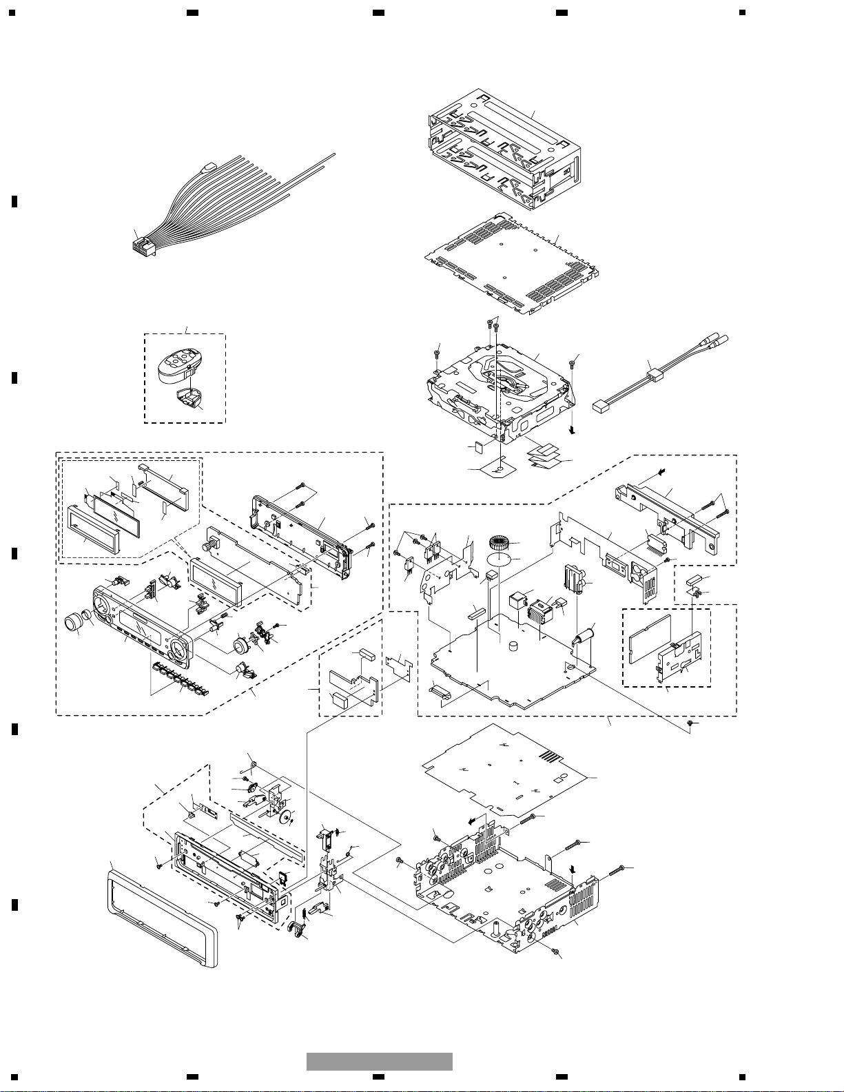
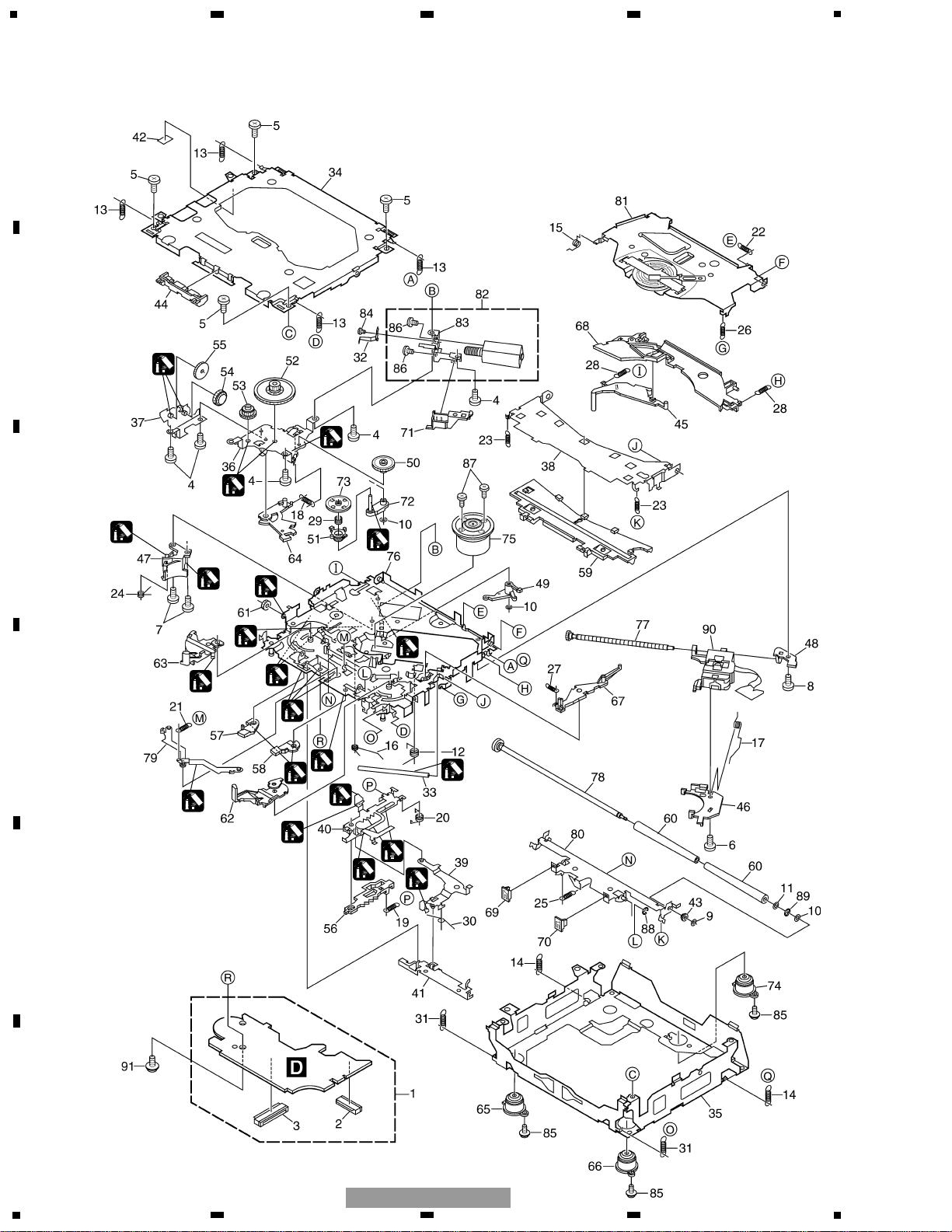
2.4 CD MECHANISM MODULE
1
1
1
2
2
1
2
2
2
1
1
1
1
1
1
1
2
1
1
3
1
1GEM1024
2GEM1045
3GEM1035

15
5
6
7
8
F
E
D
C
B
A
5
6
7
8
DEH-P650/XN/UC
Mark No. Description Part No. Mark No. Description Part No.
- CD MECHANISM MODULE SECTION PARTS LIST
1 CD Core Unit(S10) CWX2708
2 Connector(CN101) CKS4182
3 Connector(CN701) CKS4188
4 Screw BMZ20P035FTC
5 Screw BSZ20P040FTC
6 Screw(M2x4) CBA1362
7 Screw(M2x3) CBA1511
8 Screw(M2x3) CBA1527
9 Washer CBF1037
10 Washer CBF1038
11 Washer CBF1060
12 Spring CBH2390
13 Spring CBH2606
14 Spring CBH2607
15 Spring CBH2608
16 Spring CBH2609
17 Spring CBH2610
18 Spring CBH2611
19 Spring CBH2612
20 Spring CBH2613
21 Spring CBH2614
22 Spring CBH2615
23 Spring CBH2616
24 Spring CBH2617
25 Spring CBH2620
26 Spring CBH2621
27 Spring CBH2641
28 Spring CBH2642
29 Spring CBH2643
30 Spring CBH2659
31 Spring CBH2688
* 32 Spring CBL1614
33 Shaft CLA3845
34 Frame CNC9962
35 Frame CNC9963
36 Bracket CNC9966
37 Bracket CNC9967
38 Arm CNC9968
39 Arm CNC9973
40 Lever CNC9983
41 Lever CNC9984
42 Sheet CNM8134
43 Collar CNV6906
44 Guide CNV6925
45 Arm CNV7198
46 Rack CNV7199
47 Holder CNV7201
48 Holder CNV7202
49 Arm CNV7203
50 Gear CNV7207
51 Gear CNV7208
52 Gear CNV7209
53 Gear CNV7210
54 Gear CNV7211
55 Gear CNV7212
56 Rack CNV7214
57 Arm CNV7215
58 Arm CNV7216
59 Guide CNV7217
60 Roller CNV7218
61 Gear CNV7219
62 Arm CNV7221
63 Arm CNV7220
64 Arm CNV7222
65 Damper CNV7313
66 Damper CNV7314
67 Arm CNV7341
68 Arm CNV7342
69 Guide CNV7360
70 Guide CNV7361
71 Holder CNV7437
72 Arm CNV7444
73 Gear CNV7595
74 Damper CNV7618
75 Motor Unit(M1) CXB6007
76 Chassis Unit CXB8728
77 Screw Unit CXB8729
78 Gear Unit CXB8731
79 Arm Unit CXB8732
80 Arm Unit CXB8735
81 Arm Unit CXB8852
82 Motor Unit(M2) CXB8933
83 Bracket CNC9985
84 Screw JFZ20P020FTC
85 Screw(M2x5) EBA1028
86 Screw JFZ20P020FTC
87 Screw JGZ17P022FTC
88 Washer YE15FTC
89 Washer YE20FTC
90 Pickup Unit(Service)(P10) CXX1641
91 Screw IMS26P030FMC
16
1
234
12
34
F
E
D
C
B
A
DEH-P650/XN/UC
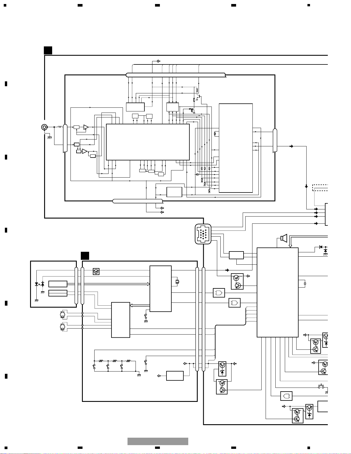
3. BLOCK DIAGRAM AND SCHEMATIC DIAGRAM
3.1 BLOCK DIAGRAM
CN701
CN101
Q101
M
LASER
DIODE
MONITOR
DIODE
CLAMP
HOME
X201
12EJ 8EJ DSCSNS
FOCUS ACT.
SPINDLE
MOTOR
M
CARRIAGE
MOTOR
LOADING/
TRACKING ACT.
LD+
MD
FOP
TOP
14
5
4
1
PICKUP UNIT
(SERVICE)(P10)
HOLOGRAM
UNIT
IC 301
BA5996FP
IC 201
UPD63712GC
IC 701
NJM2391DL1-33
3.3V REGULATOR
SERVO
CONTROL,
DSP,
LPF, DAC
ACT,MOTOR
DRIVER
1
VD
VD
3R3V
7
CONT
11
CLMP
5
LOEJ
6
DSCSNS
8
LOUT
TOP
FOP
16
SOP
15
SOM
17
LCOM
18
LCOP
22
1
LOEJ
23
20
LOUT
XTAL
xtal
24
9
CONT
12
FOP
FD, TD, SD, MD
AC, F, E, BD
1
LD
2
PD
42
LIMIT
3
13
TOP
D
CD CORE UNIT(S10)
D
2
16
SO
12
XSI
4
INTQ
7
INTQ
ASENBO
85
mute
XIN
XOUT
IN
41
PEE
22
38
IN
43
IN
44
IN
42
80
28
27
79
SYSTEM CONTROLLER
IC 601(2/2)
PD5807A
CN401
1
2
BUS-
BUS+
BUS+L
BUS-L
TX
RX
IPPW
EL
S
SWVDD
CN651
Q807
TUNER AMP UNIT
13
X601
11
EVST,EVCK,EVDT
TUN L
BUS+L
BUS-L
CD L
33
DPDT
34
KYDT
1
SYSPW
EJTIN
42
41
ILMPW
S802
DSENS
39
dsens
A
5
8
1
7
CN101
11
BUZZER
14
IC 101
HA12187FP
IP-BUS DRIVER
1
2
8
6
5
TX
RX
IPPW
BU
Q101
Q102
TUN 3.3V
SYS 8.4V
VDD
ANTENNA
92
LVLINL
LEVEL INDICAT
BU
Q804
Q803
20
OELPW
BU
Q852
Q851
IC 85
NJM23
6
BZ 641
TC7SET08FU
IC 801
24
35
ROT136ROT0
VDD
Q808
BU
Q652
Q651
20
15
11
17
16
21
CDLOEJ
23
CONT
56
DSCSNS
87
xtalen
66
32
VDCONT
CLMP
TC7SET08FU
IC 653
24
XSI
4
6
80
VDSENS
VDSENS
TC7SET08FU
IC 652
24
INTQ
18
18
15
ASLIN
DEH-P65
N
FLPILM
40
FMRF
ANT adj
RF adj
FM ANT
T51
CF52
CF51
RFGND
OSCGND
DGND
AUDIOGNDNCVCC
VDD_3.3
3.3V
2.5V
IC 4
3.3V 2.5V
←
IC 2
2.5V
WC
CE2
ROM_VDD
SL
DI
CK
CE1
NC
DO
NCNCNC
NC
7 6 13 5 10 9 8 11 14 18 19 20 21
1
3
212 1522 16 4 17
IC 1
3.3V
AM ANT
FMRF
ATT
LPF
OSC
IC 3 EEPROM
5.0V
IC 5
5V 3.3V
←
ATT
MIXER, IF AMP
DET, FM MPX
24
23
Rch
Lch
FM/AM TUNER UNIT
17
5
6
7
8
F
E
D
C
B
A
5
6
7
8
DEH-P650/XN/UC
10
1
bsens
asens
VDD
BU
72
73
10
FL
11
RL
ILB
SWDVDD
23
21
3
5
FL-
FL+
RL-
RL+
ACC
IN2-L
41
IN4+L
43
IN4-L
44
IN3-L
42
FLIN
14
RLIN
12
22 4
RESET
POWER AMP
IC 601(1/2)
PD5807A
IC 201
PML009A
IC 602
IC 301
PAL007A
reset
VDD
Q911
Q931
SYSPW
ELECTRONIC VOLUME/
SOURCE SELECTOR
STBYMUTE
Q807
2
N L
DPDT
KYDT
SYS 8.4V
BU
Q923
Q922
BU
Q301
MUTE
PL
NON-FAD/SW L
FL
Q352
FRONT L
12
PL
7
2
11
14
7
2
11
14
CN1950
CN1951
4
2
10
8
PANEL UNIT
MUTE
S802
DSENS
SYSTEM CONTROLLER
Q951
VDD
TELIN
8
25
B.REMOTE
VDD REGULATOR
BACKUP SENSE
ACC SENSE
TELEPHONE MUTE
SYS 8.4V REGULATOR
14
8
6
5
7
16
9
11
14
8
6
5
7
16
9
11
15 15
C
CN901
Q982
BU
CN352
FUSE
10A
SL
tunce@
TUNPCE1
TUNPDI
TUNPDO
95
69
70
98
99
TUNPCK
100
ce@
CE1
NJM2391DL1-33
IC 401
13
SYS 8.4V
TUN 3.3V
TUNER 3.3V REGULATOR
Q921
DO
DI
CK
Q913
DALMON
67
BU
6,20
Q981
10 10 5
Q353
RL
Q351
1
CN351
REAR L
PL
FL
RL
Q932
isens
81
ILM SENSE
12
12
NJM4558MD
IC 131
57
1
SEL_OUT_L
MIC
13
MICIN
MICROPHONE
1
Q804
Q803
ILB
IC 851
NJM2360M
65
13
13
9
12
12
7
ROT1
ROT0
Q808
CN 751
S-80835ANUP-EDZ
FLFL+
RLRL+
BACK UP
GND
ACC
B.REM
ILM
TEL MUTE
DEH-P6550/XN/ES
15
NL1
93
ASLIN
DEH-P6550/XN/ES
NOISEDET
CN831
8
8
S1970
EJECT
9
9
DGND
BU
5
6
5
6
Q805
ILB
SWVDD
OELB
IC 1940
PD5809A
OEL CONTROLLER/
KEY CONTROLLER
9
11
8
KEY DATA
OEL DATA
AVCC
97
CN1901
KEYBOARD UNIT
3
5
DPDT
KYDT
IC 1990
FONT ROM
IC 1901
RS-140
REMOTE CONTROL
SENSOR
OPT IN
4
1
5
REM
27
28
DPDT
KTDT
OEL UNIT
4,16
2,8
IC 1902
S-818A33AUC-BGN
3.3V REGULATOR
15
B
S1901
3
2
1
4
6
ROT1
ROT0
ROT1
ROT0
KEY MATRIX
ILLUMINATION
Q1960
Q1961
IC1970 IC1971
VDD114VDD2
60
23
AVCC
DEH-P650/XN/UC
DEH-P6500/XN/UC
DEH-P6550/XN/ES
PD8108A
PD8107A
IC 1990
16V
9V
VOLUME
18
C
PANEL UNIT
B
KEYBOARD UNIT
CN701
DEH-P6500
DEH-P650
FM(100%):-19.5dBs
AM(30%):-30dBs
FM/AM TUNER UNIT
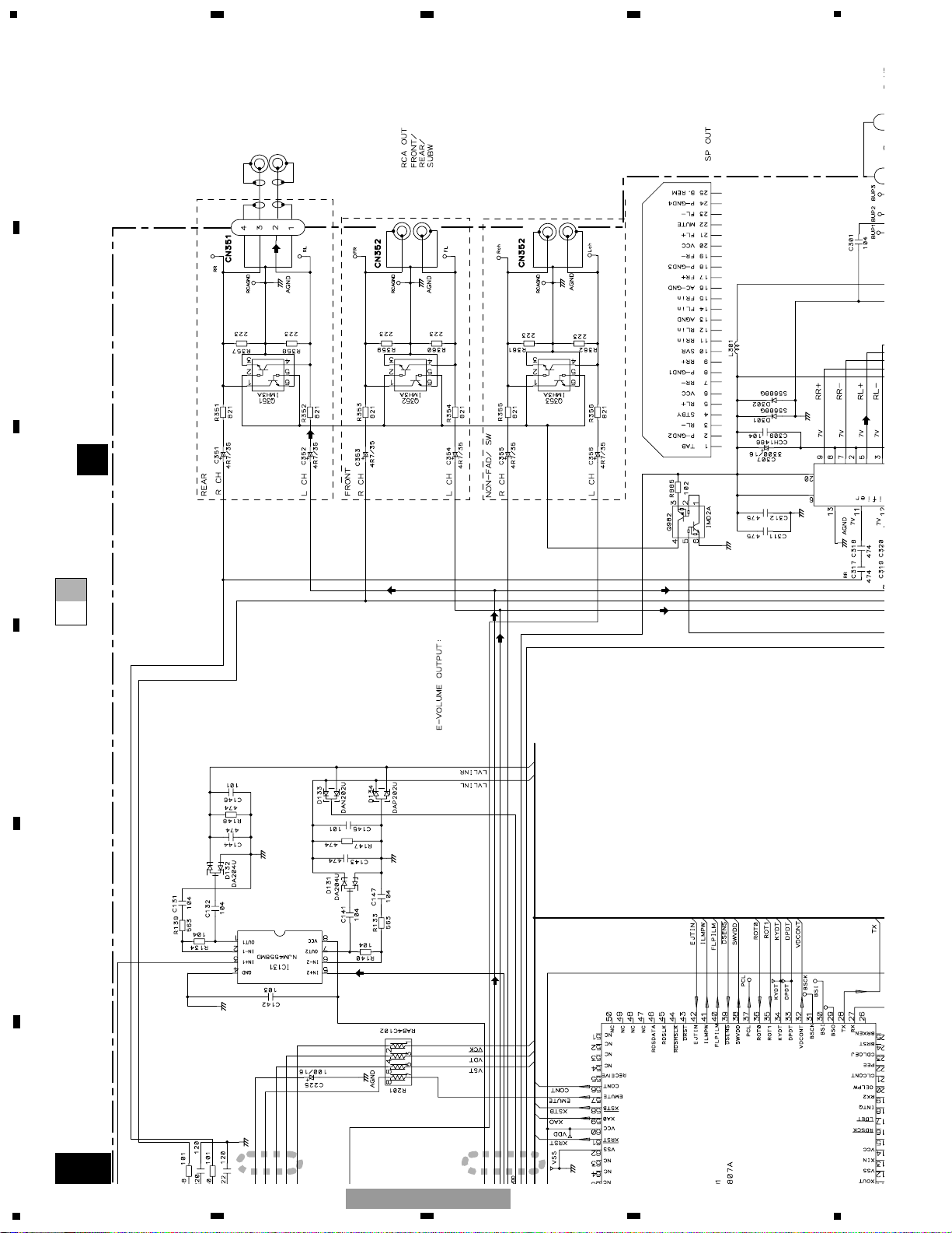
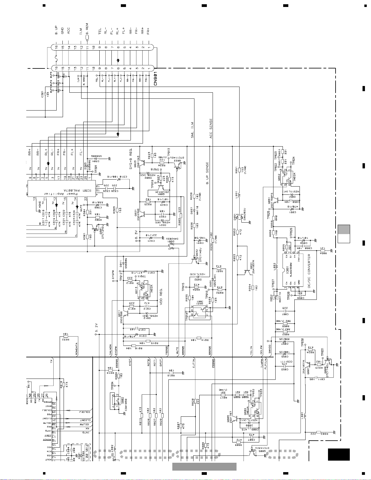
For resistors and capacitors in the circuit diagrams, their resistance values or
capacitance values are expressed in codes:
Ex. *Resistors
Code Practical value
123 12k ohms
103 10k ohms
*Capacitors
Code Practical value
103 0.01uF
101/10 100uF/10V
D
CD CORE UNIT(S10)
EJECT
SYS
ANTENNA
1
234
12
34
F
E
D
C
B
A
DEH-P650/XN/UC
3.2 OVERALL CONNECTION DIAGRAM(GUIDE PAGE)
(DEH-P650/XN/UC, P6500/XN/UC)
Note: When ordering service parts, be sure to refer to “EXPLODED VIEWS AND PARTS LIST” or “ELECTRICAL PARTS
LIST”.
A
C
A-aA-a A-b A-b
A-aA-a
A-b A-b
A-b A-b
A-a A-a
Large size
SCH diagram
Guide page
Detailed page
19
5
6
7
8
F
E
D
C
B
A
5
6
7
8
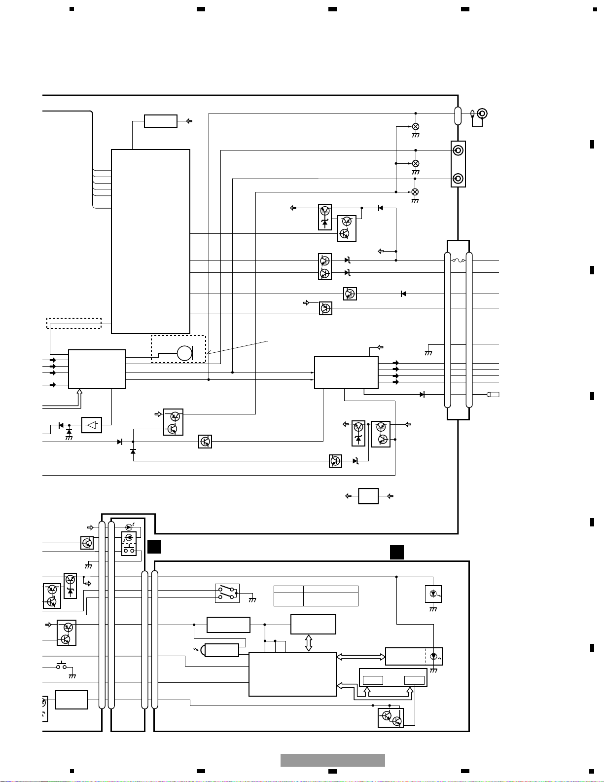
DEH-P650/XN/UC
A
CEK1208
10A
FUSE
>
REAR
R CH
REAR
L CH
A
TUNER AMP UNIT
SUB WOOFER
R CH
SUB WOOFER
L CH
FM(100%):+21.1dBs
AM(30%):+21.1dBs
CD:+36.46dBs
IP-BUS:+35.3dBs
FM(100%):-5.7dBs
AM(30%):-5.7dBs
CD:+36.46dBs
IP-BUS:+9.66dBs
FM(100%):+5.6dBs
AM(30%):-4.9dBs
CD:+10.46dBs
IP-BUS:+9.3dBs
FRONT
R CH
FRONT
L CH
DSENS
600µH
SYSTEM CONTROLLER
(1/2)
(2/2)
20
1
234
12
34
F
E
D
C
B
A
DEH-P650/XN/UC
A-a
A-b
A-a
A-a
A-b
1
2
DEH-P6500
DEH-P650
FM(100%):-19.5dBs
AM(30%):-30dBs
FM/AM TUNER UNIT
SYSTEM CONTRO
ANTENNA
21
5
6
7
8
F
E
D
C
B
A
5
6
7
8
DEH-P650/XN/UC
A-a
C
A-a
A-b
A-a
A-a
A-b
3
4
5
6
C
PANEL UNIT
B
KEYBOARD UNIT
CN701
For resistors and capacitors in the circuit diagrams, their resistance values or
capacitance values are expressed in codes:
Ex. *Resistors
Code Practical value
123 12k ohms
103 10k ohms
*Capacitors
Code Practical value
103 0.01uF
101/10 100uF/10V
D
CD CORE UNIT(S10)
EJECT
22
1
234
12
34
F
E
D
C
B
A
DEH-P650/XN/UC
A-a
A-b
A-b
1
2
FUSE
>
REAR
R CH
REAR
L CH
A
TUNER AMP UNIT
SUB WOOFER
R CH
SUB WOOFER
L CH
FM(100%):+21.1dBs
AM(30%):+21.1dBs
CD:+36.46dBs
IP-BUS:+35.3dBs
FM(100%):-5.7dBs
AM(30%):-5.7dBs
CD:+36.46dBs
IP-BUS:+9.66dBs
FM(100%):+5.6dBs
AM(30%):-4.9dBs
CD:+10.46dBs
IP-BUS:+9.3dBs
FRONT
R CH
FRONT
L CH
600µH
(1/2)
(2/2)
23
5
6
7
8
F
E
D
C
B
A
5
6
7
8
DEH-P650/XN/UC
A-a
A-b
A-b
3
4
5
6
CEK1208
10A
FUSE
>
DSENS
 Loading...