

Pioneer DEHP-4800-MP, DEHP-480-MP Service manual
ORDER NO.
CRT3566
DEH-P480MP/XU/UC
MULTI-CD CONTROL HIGH POWER CD/MP3/WMA PLAYER WITH FM/AM TUNER
DEH-P480MP
DEH-P4800MP
This service manual should be used together with the following manual(s):
Model No. Order No. Mech. Module Remarks
CX-3164 CRT3583 S10.5COMP1 CD Mech. Module:Circuit Description, Mech. Description, Disassembly
/XU/UC
/XU/UC
For details, refer to "Important Check Points for Good Servicing".
PIONEER CORPORATION 4-1, Meguro 1-chome, Meguro-ku, Tokyo 153-8654, Japan
PIONEER ELECTRONICS (USA) INC. P.O. Box 1760, Long Beach, CA 90801-1760, U.S.A.
PIONEER EUROPE NV Haven 1087, Keetberglaan 1, 9120 Melsele, Belgium
PIONEER ELECTRONICS ASIACENTRE PTE. LTD. 253 Alexandra Road, #04-01, Singapore 159936
PIONEER CORPORATION 2005
K-ZZA. NOV. 2005 Printed in Japan
1234
SAFETY INFORMATION
CAUTION
A
This service manual is intended for qualified service technicians; it is not meant for the casual do-it-yourselfer.
Qualified technicians have the necessary test equipment and tools, and have been trained to properly and safely repair
complex products such as those covered by this manual.
Improperly performed repairs can adversely affect the safety and reliability of the product and may void the warranty.
If you are not qualified to perform the repair of this product properly and safely, you should not risk trying to do so
and refer the repair to a qualified service technician.
W
ARNING
This product contains lead in solder and certain electrical parts contain chemicals which are known to the state of
California to cause cancer, birth defects or other reproductive harm.
B
Health & Safety Code Section 25249.6 - Proposition 65
- CD Section Precaution
1. You should conform to the regulations governing
the product (safety, radio and noise, and other
regulations), and should keep the safety during
servicing by following the safety instructions
described in this manual.
2. Before disassembling the unit, be sure to turn off
C
the power. Unplugging and plugging the connectors
during power-on mode may damage the ICs inside
the unit.
3. To protect the pickup unit from electrostatic discharge
during servicing, take an appropriate treatment
(shorting-solder) by referring to "the DISASSEMBLY".
4. After replacing the pickup unit, be sure to check the
grating.
D
E
F
2
1234
DEH-P480MP/XU/UC
5678
[Important Check Points for Good Servicing]
In this manual, procedures that must be performed during repairs are marked with the below symbol.
Please be sure to confirm and follow these procedures.
1. Product safety
Please conform to product regulations (such as safety and radiation regulations), and maintain a safe servicing environment by
following the safety instructions described in this manual.
1 Use specified parts for repair.
Use genuine parts. Be sure to use important parts for safety.
2 Do not perform modifications without proper instructions.
Please follow the specified safety methods when modification(addition/change of parts) is required due to interferences such as
radio/TV interference and foreign noise.
3 Make sure the soldering of repaired locations is properly performed.
When you solder while repairing, please be sure that there are no cold solder and other debris.
Soldering should be finished with the proper quantity. (Refer to the example)
4 Make sure the screws are tightly fastened.
Please be sure that all screws are fastened, and that there are no loose screws.
5 Make sure each connectors are correctly inserted.
Please be sure that all connectors are inserted, and that there are no imperfect insertion.
6 Make sure the wiring cables are set to their original state.
Please replace the wiring and cables to the original state after repairs.
In addition, be sure that there are no pinched wires, etc.
7 Make sure screws and soldering scraps do not remain inside the product.
Please check that neither solder debris nor screws remain inside the product.
8 There should be no semi-broken wires, scratches, melting, etc. on the coating of the power cord.
Damaged power cords may lead to fire accidents, so please be sure that there are no damages.
If you find a damaged power cord, please exchange it with a suitable one.
9 There should be no spark traces or similar marks on the power plug.
When spark traces or similar marks are found on the power supply plug, please check the connection and advise on secure
connections and suitable usage. Please exchange the power cord if necessary.
0 Safe environment should be secured during servicing.
When you perform repairs, please pay attention to static electricity, furniture, household articles, etc. in order to prevent injuries.
Please pay attention to your surroundings and repair safely.
A
B
C
D
2. Adjustments
To keep the original performance of the products, optimum adjustments and confirmation of characteristics within specification.
Adjustments should be performed in accordance with the procedures/instructions described in this manual.
3. Lubricants, Glues, and Replacement parts
Use grease and adhesives that are equal to the specified substance.
Make sure the proper amount is applied.
4. Cleaning
For parts that require cleaning, such as optical pickups, tape deck heads, lenses and mirrors used in projection monitors, proper
cleaning should be performed to restore their performances.
5. Shipping mode and Shipping screws
To protect products from damages or failures during transit, the shipping mode should be set or the shipping screws should be
installed before shipment. Please be sure to follow this method especially if it is specified in this manual.
56
DEH-P480MP/XU/UC
E
F
7
8
3

1234
CONTENTS
SAFETY INFORMATION ..................................................................................................................................... 2
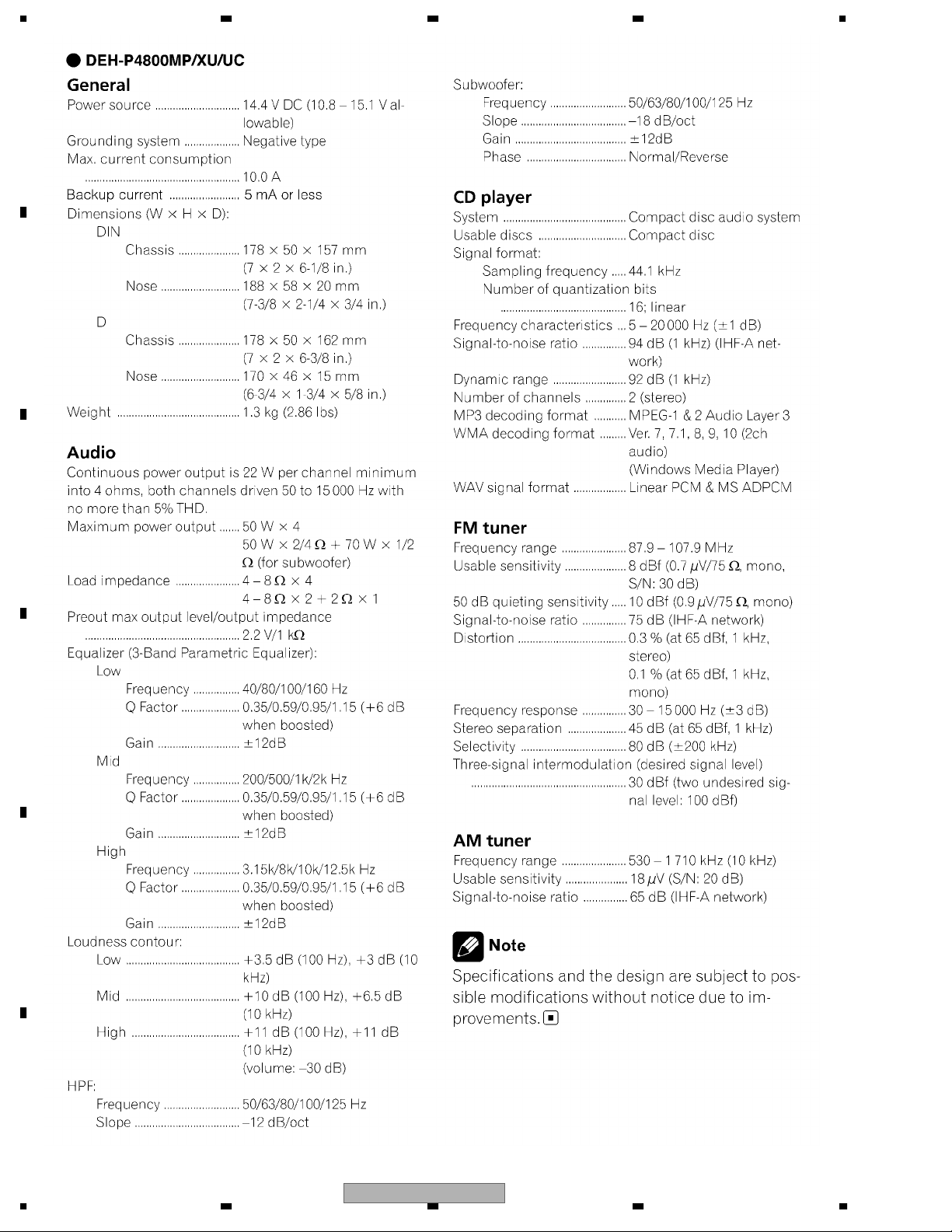
1. SPECIFICATIONS ............................................................................................................................................ 5
2. EXPLODED VIEWS AND PARTS LIST ............................................................................................................ 7
A
B
C
2.1 PACKING ................................................................................................................................................... 7
2.2 EXTERIOR................................................................................................................................................. 8
2.3 CD MECHANISM MODULE..................................................................................................................... 10
3. BLOCK DIAGRAM AND SCHEMATIC DIAGRAM ..........................................................................................12
3.1 BLOCK DIAGRAM ................................................................................................................................... 12
3.2 OVERALL CONNECTION DIAGRAM(GUIDE PAGE).............................................................................. 14
3.3 KEYBOARD UNIT.................................................................................................................................... 20
3.4 CD MECHANISM MODULE(GUIDE PAGE) ............................................................................................ 22
4. PCB CONNECTION DIAGRAM ..................................................................................................................... 32
4.1 TUNER AMP UNIT................................................................................................................................... 32
4.2 KEYBOARD UNIT.................................................................................................................................... 36
4.3 PANEL UNIT ............................................................................................................................................ 37
4.4 CD CORE UNIT(S10.5COMP1)............................................................................................................... 38
5. ELECTRICAL PARTS LIST ............................................................................................................................ 40
6. ADJUSTMENT ............................................................................................................................................... 48
6.1 CD ADJUSTMENT................................................................................................................................... 48
6.2 CHECKING THE GRATING AFTER CHANGING THE PICKUP UNIT .................................................... 50
6.3 ERROR MODE ........................................................................................................................................ 52
6.4 SYSTEM MICROCOMPUTER TEST PROGRAM ................................................................................... 53
7. GENERAL INFORMATION ............................................................................................................................. 54
7.1 DIAGNOSIS ............................................................................................................................................. 54
7.1.1 DISASSEMBLY ..................................................................................................................................... 54
7.1.2 CONNECTOR FUNCTION DESCRIPTION.......................................................................................... 57
7.2 PARTS...................................................................................................................................................... 58
7.2.1 IC .......................................................................................................................................................... 58
7.2.2 DISPLAY ............................................................................................................................................... 68
7.3 OPERATIONAL FLOW CHART ............................................................................................................... 69
8. OPERATIONS ................................................................................................................................................ 70
D
E
F
4
1234
DEH-P480MP/XU/UC
5678
1. SPECIFICATIONS
A
B
C
D
E
56
DEH-P480MP/XU/UC
F
7
8
5
1234
A
B
C
D
E
F
6
1234
DEH-P480MP/XU/UC
N
5678
2. EXPLODED VIEWS AND PARTS LIST
OTES : • Parts marked by " * " are generally unavailable because they are not in our Master Spare Parts List.
• The > mark found on some component parts indicates the importance of the safety factor of the part.
Therefore, when replacing, be sure to use parts of identical designation.
• Screw adjacent to mark on the product are used for disassembly.
• For the applying amount of lubricants or glue, follow the instructions in this manual.
(In the case of no amount instructions,apply as you think it appropriate.)
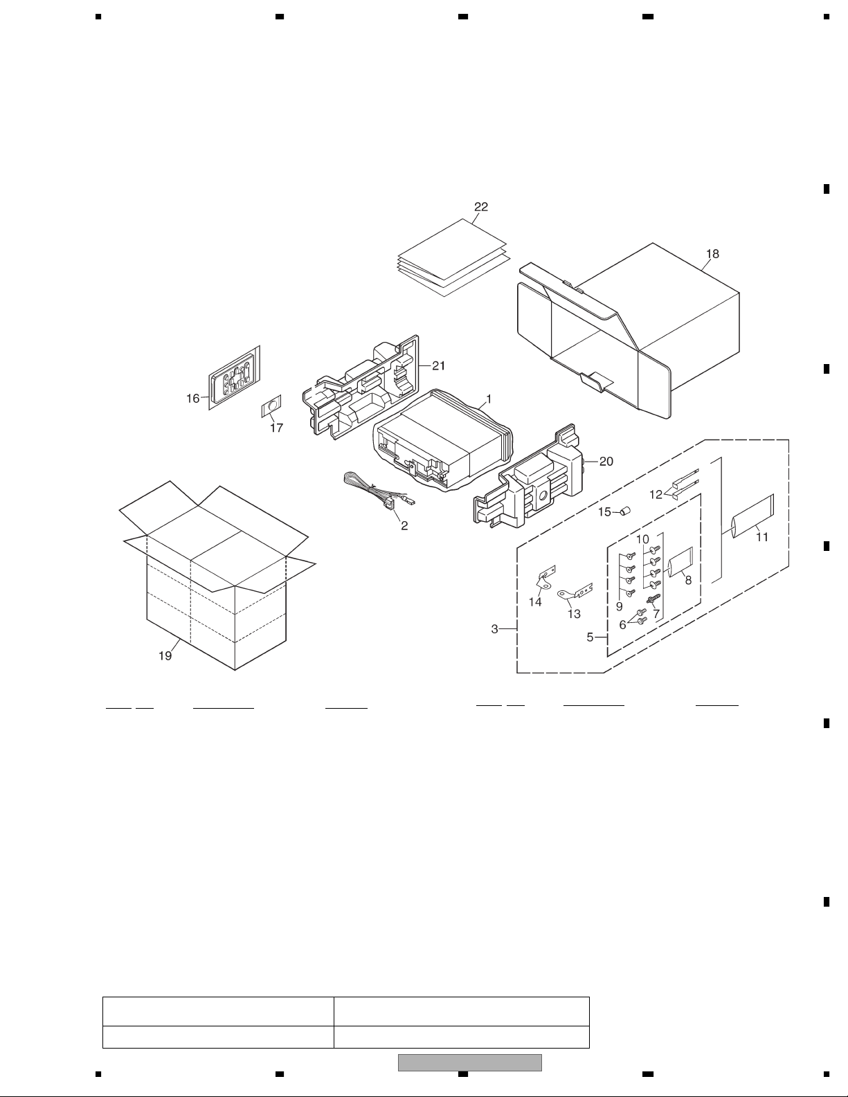
2.1 PACKING
"
A
B
PACKING SECTION PARTS LIST
No. Description Part No.
Mark
1 Polyethylene Bag CEG1173
2 Cord Assy XDE7008
* 3 Accessory Assy YEA5008
4 •••••
5 Screw Assy YEA5007
6 Fixing Screw BPZ20P060FTB
7 Screw CBA1650
* 8 Polyethylene Bag CEG-127
9 Screw CRZ50P090FTC
10 Screw TRZ50P080FTC
* 11 Polyethylene Bag CEG-158
12 Handle CNC5395
13 Holder CND1249
14 Holder CND1250
15 Bush CNV3930
No. Description Part No.
Mark
16 Remote Control Assy CXC5719
* 17 Battery CEX1065
18 Carton(P480MP) YHG5078
Carton(P4800MP) YHG5077
19 Contain Box(P480MP) YHL5055
Contain Box(P4800MP) YHL5054
20 Protector YHP5008
21 Protector YHP5009
22-1 Owner's Manual(P480MP) YRD5038
Owner's Manual(P4800MP) YRD5037
22-2 Installation Manual(P480MP) YRD5043
Installation Manual(P4800MP) YRD5042
22-3 Caution Card CRP1310
* 22-4 Warranty Card(P480MP) CRY1070
* Warranty Card(P4800MP) CRY1246
22-5 Caution Card(P4800MP) CRP1294
C
D
E
Owner's Manual,Installation Manual
Part No. Language
YRD5038,YRD5037,YRD5043,YRD5042 English, French, Spanish
DEH-P480MP/XU/UC
56
F
7
8
7
1234
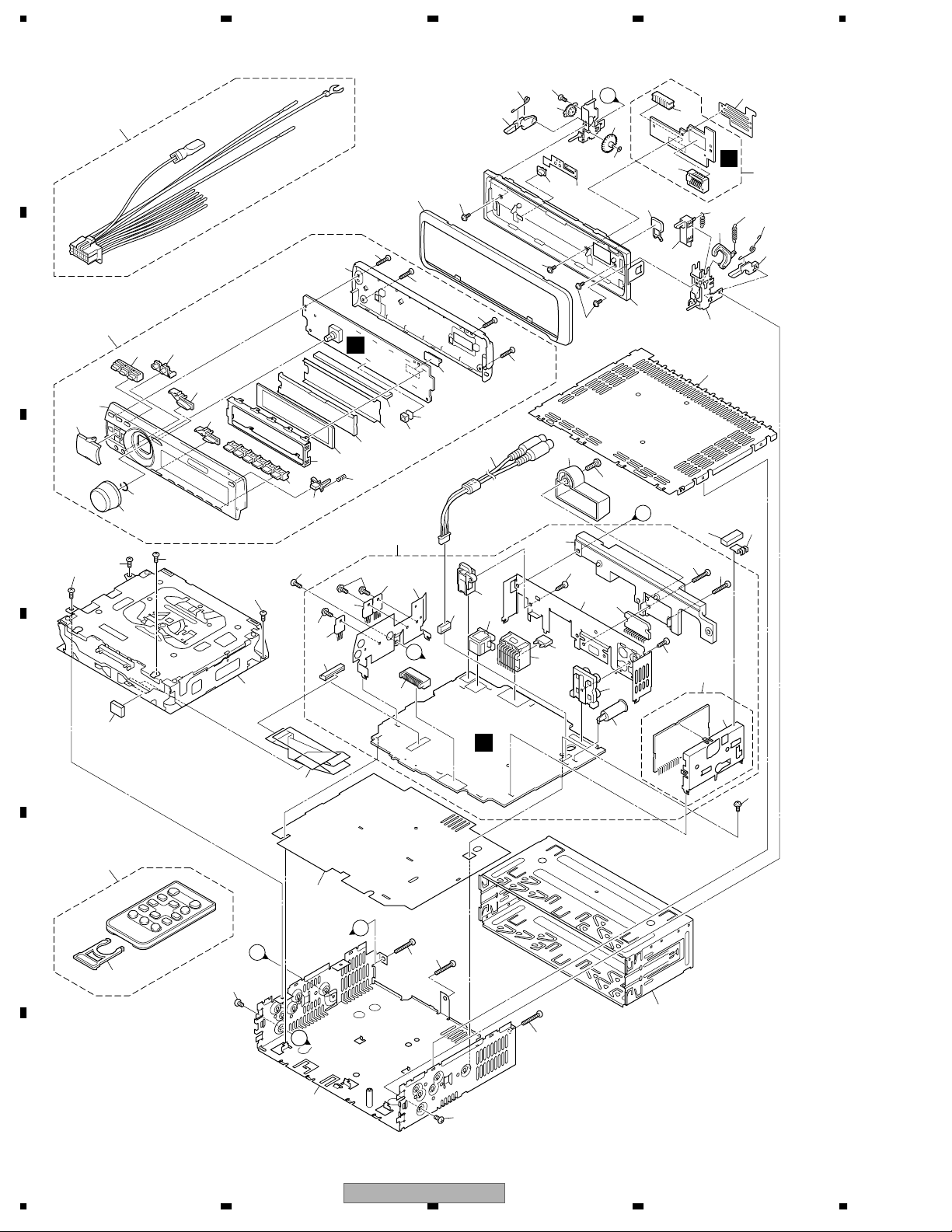
2.2 EXTERIOR
A
13
59
75
73
A
76
79
67
62
69
22
32
D
77
65
64
63
72
70
74
17
8
7
22
33
61
68
60
25
36
23
87
21
66
60
35
86
83
24
29
18
60
38
48
38
53
49
27
38
38
16
34
30
B
37
41
20
84
28
51
50
84
B
39
20
55
54
52
85
82
19
31
B
26
46
45
42
56
57
C
3
D
47
40
3
9
43
44
3
3
12
4
A
78
58
71
80
C
21
15
10
14
E
B
11
F
8
1234
2
A
A
81
C
5
5
2
DEH-P480MP/XU/UC
6
5
1

5678
EXTERIOR SECTION PARTS LIST
Mark No. Description Part No.
1 Screw ASZ26P050FTC
2 Screw BMZ30P040FTB
3 Screw BSZ26P060FTC
4 Screw BSZ30P060FTC
5 Screw BSZ30P200FTC
6 Holder CNC8659
7 Earth Plate CNC8915
8 Cushion CNM8890
9 Insulator CNM7682
10 Remote Control Assy CXC5719
11 Cover CNS7068
12 CD Mechanism Module(S10.5) CXK5750
13 Cord Assy XDE7008
14 Insulator XNM7100
15 Cable YDE5013
16 Cord Assy YDE5014
17 Case YNB5008
18 Panel(P480MP) YNS5157
Panel(P4800MP) YNS5114
19 Tuner Amp Unit(P480MP) YWM5085
Tuner Amp Unit(P4800MP) YWM5087
20 Screw ASZ26P060FTC
21 Screw BPZ26P080FTC
22 Screw BSZ26P160FTC
> 23 Fuse(10 A) CEK1208
24 Pin Jack(CN353) CKB1051
25 Plug(CN901) CKM1376
26 Plug(CN801) CKS3537
27 Connector(CN352) CKS3584
28 Connector(CN701) CKS3834
29 Antenna Jack(CN401) CKX1056
30 Connector(CN101) CKS5271
31 Holder CND1352
32 FM/AM Tuner Unit CWE1957
33 Holder CND1054
34 JACK(CN621) YKS5001
35 Holder YNC5015
36 Heat Sink YNR5004
37 Detachable Assy(P480MP) YXA5104
Detachable Assy(P4800MP) YXA5105
38 Screw BPZ20P100FTB
39 Spring CBH2210
40 Knob(SOURCE,VOLUME) YAA5006
41 Button(OPEN) YAC5067
42 Button(EQ) YAC5068
43 Button(BAND) YAC5069
Mark No. Description Part No.
46 Button
Button
(CLOCK,DISPLAY)(P480MP)
(CLOCK,DISPLAY)(P4800MP)
YAC5098
YAC5073
47 Spring YBH5003
48 Cover YNS5113
49 Connector(CN1801) CKS5207
50 LCD(LCD1801) YAW5051
51 Holder YNC5013
52 Sheet YNM5015
53 Spacer YNM5016
54 Connector YNV5030
55 Lighting Conductor YNV5032
56 Grille Unit(P480MP) YXA5159
Grille Unit(P4800MP) YXA5127
57
Button Unit
Button Unit
(UP,DOWN,LEFT,RIGHT)(P480MP)
(UP,DOWN,LEFT,RIGHT)(P4800MP)
YXC5025
YXC5022
58 Button(EJECT) CAC7752
59 Screw(M2 x 4) CBA1649
60 Screw(M2 x 4.5) CBA1925
61 Washer CBF1038
62 Spring CBH2650
63 Spring CBH2651
64 Spring CBH2652
65 Spring CBH2653
66 Spring CBL1512
67 Holder CND1254
68 Pin CNV6486
69 Arm CNV7400
70 Arm CNV7401
71 Arm CNV7402
72 Arm CNV7403
73 Holder Unit CXB9501
74 Holder Unit CXB9502
75 Damper Unit CXB9503
76 Gear YNV5053
77 Panel Unit YWM5099
78 Connector(CN1901) CKS4806
79 Connector(CN1902) CKS5192
80 Sub Panel Unit YXA5160
81 Chassis Unit YXA5131
82 IC(IC1801) TSOP4840SB1
83 IC(IC301) PAL007B
84 Transistor(Q702,Q911) 2SD2396
85 IC(IC921) NJM2388F84
86 Screw(P4800MP) BMZ40P140FTC
87 Holder(P4800MP) CNV7619
A
B
C
D
E
44 Button(1-6) YAC5070
45 Button
Button
(AUDIO,FUNCTION,SW)(P480MP)
(AUDIO,FUNCTION,SW)(P4800MP)
YAC5096
YAC5072
56
DEH-P480MP/XU/UC
F
7
8
9
1234
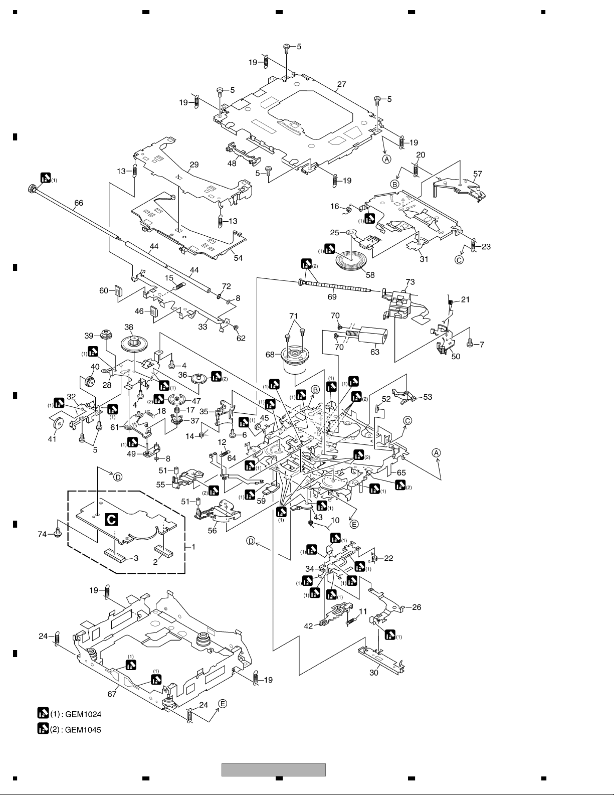
2.3 CD MECHANISM MODULE
A
B
C
D
E
F
10
1234
DEH-P480MP/XU/UC

5678
CD MECHANISM MODULE SECTION PARTS LIST
Mark No. Description Part No.
1 CD Core Unit(S10.5COMP1) CWX3176
2 Connector(CN101) CKS4808
3 Connector(CN901) CKS5284
4 Screw BMZ20P025FTC
5 Screw BSZ20P040FTC
6 Screw(M2 x 3) CBA1511
7 Screw(M2 x 4) CBA1835
8 Washer CBF1038
9 •••••
10 Spring CBH2609
11 Spring CBH2612
12 Spring CBH2614
13 Spring CBH2616
14 Spring CBH2617
15 Spring CBH2620
16 Spring CBH2855
17 Spring CBH2937
18 Spring CBH2735
19 Spring CBH2854
20 Spring CBH2642
21 Spring CBH2856
22 Spring CBH2857
23 Spring CBH2860
24 Spring CBH2861
25 Spring CBL1686
26 Arm CND1909
27 Frame CND2582
28 Bracket CND2583
29 Arm CND2584
30 Lever CND2585
Mark No. Description Part No.
50 Rack CNV8342
51 Roller CNV8343
52 Holder CNV8344
53 Arm CNV8345
54 Guide CNV8347
55 Arm CNV8348
56 Arm CNV8349
57 Arm CNV8350
58 Clamper CNV8365
59 Arm CNV8386
60 Guide CNV8396
61 Arm CNV8413
62 Collar CNV8447
63 Motor Unit(M2) CXC4026
64 Arm Unit CXC4027
65 Chassis Unit CXC4028
66 Gear Unit CXC4029
67 Frame Unit CXC4031
68 Motor Unit(M1) CXC6742
69 Screw Unit CXC6359
70 Screw JFZ20P020FTC
71 Screw JGZ17P022FTC
72 Washer YE20FTC
73 Pickup Unit(P10.5)(Service) CXX1942
74 Screw IMS26P030FTC
A
B
C
D
31 Arm CND2586
32 Bracket CND2587
33 Arm CND2588
34 Lever CND2589
35 Holder CNV7201
36 Gear CNV7207
37 Gear CNV7208
38 Gear CNV7209
39 Gear CNV7210
40 Gear CNV7211
41 Gear CNV7212
42 Rack CNV7214
43 Arm CNV7216
44 Roller CNV8189
45 Gear CNV7219
46 Guide CNV7361
47 Gear CNV7595
48 Guide CNV8448
49 Arm CNV7805
56
DEH-P480MP/XU/UC
E
F
7
8
11
E
R
2
B
1234
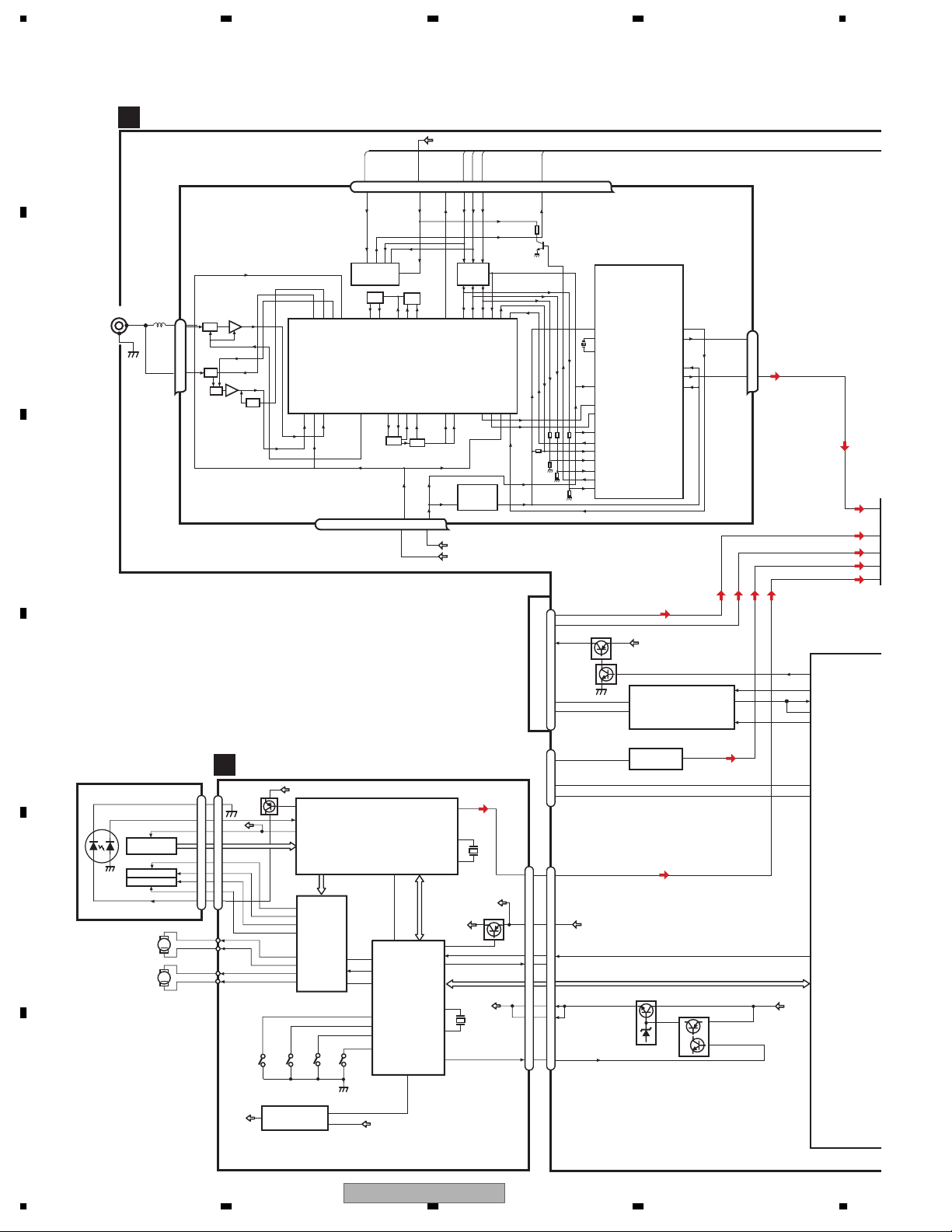
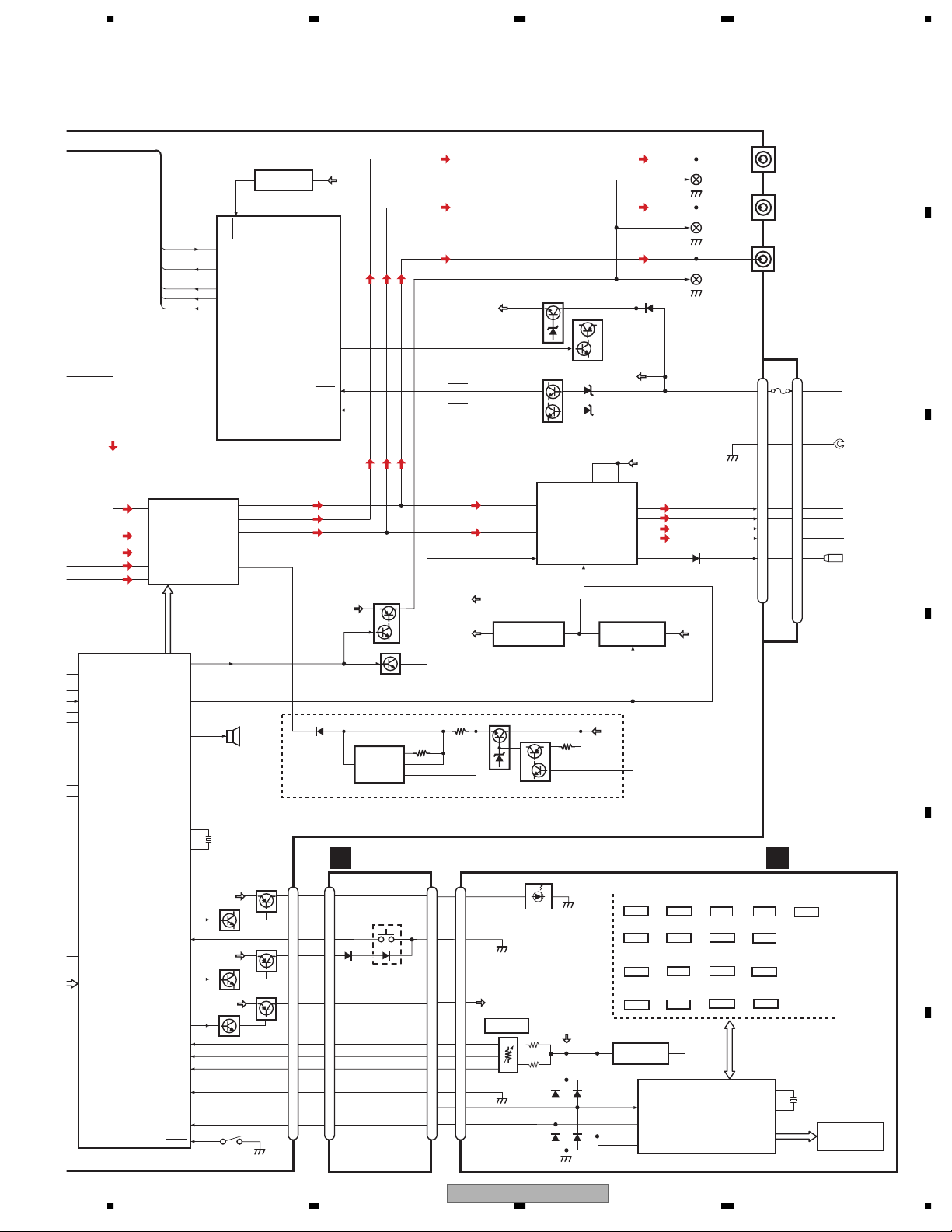
3. BLOCK DIAGRAM AND SCHEMATIC DIAGRAM
3.1 BLOCK DIAGRAM
A
ANTENNA
B
C
D
PICKUP UNIT
(P10.5)(SERVICE)
LASER
DIODE
E
F
TUNER AMP UNIT
A
CN401
1
2
HOLOGRAM
FOCUS ACT.
MONITOR
TRACKING ACT.
DIODE
SPINDLE
MOTOR
CARRIAGE
LOAD/
MOTOR
FM/AM TUNER UNIT
AM ANT
1
ATT
FM ANT
3
ATT
LD-
15
MD
5
VREF
UNIT
FOM
FOP
2
TOP
1
TOM
LD+
14
M
M
FMRF
FMRF
RF adj
ANT adj
RFGND
212 152216 4 17
CD CORE UNIT(S10.5COMP1)
C
D
F,E
S905
8EJ
4
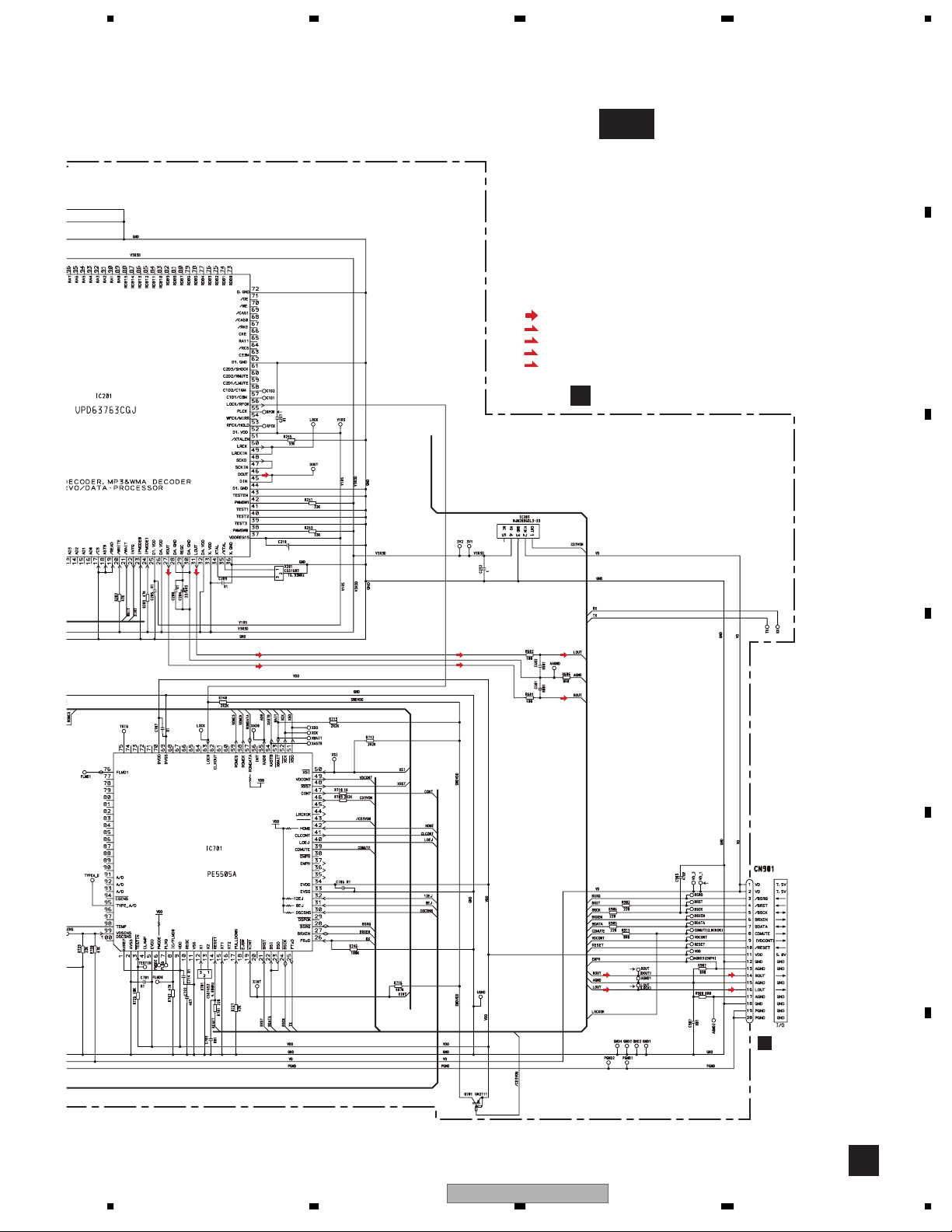
NJM2886DL3-33
V3R3D
142
LD
143
PD
133
REFOUT
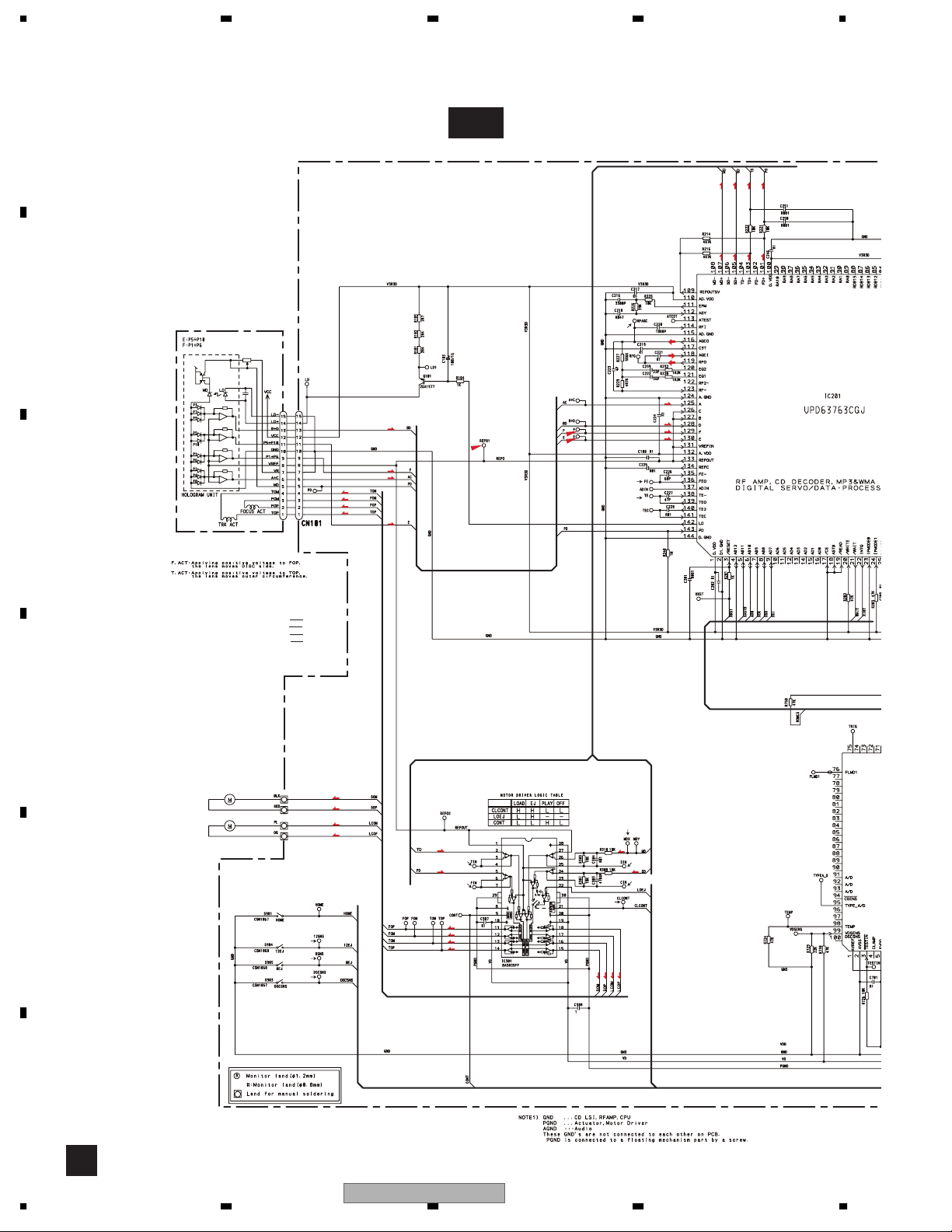
RF-AMP,CD DECODER,
MP3 , WMA, DECODER,
DIGITAL SERVO / DATA PROCESSOR
TD,FD
SD,MD
CD
12
FOM
DRIVER
11
FOP
14
TOP
13
TOM
IC301
BA5835FP
16
SOP
CLCONT
15
SOM
18
LOEJ
LCOP
17
CONT
LCOM
S903
DSCSNS
1
IC203
3
15
5
88
33
2
1
44
14
CN101
REFO
FOM
FOP
TOP
TOM
V3R3D
Q101
AC,BD
S904
12EJ
+3.3V REGULATOR
VDD5
TUNPDI
VDD_3.3
SL
3.3V
VDD_3.3V
VCC8
TUNPCK
DI
IC 5
←
5V 3.3V
IC 4
3.3V 2.5V
CK
CE1
←
76 13 5 1098 11 14 18192021
NC
CE2
ROM_VDD
IC 3 EEPROM
5.0V
OSC
LPF
IC 1
3.3V
MIXER, IF AMP
T51
CF52
OSCGND
DGND
AUDIOGNDNCVCC
TUNPDO
NC
DO
2.5V
CN101
BUSL−
11
BUSL+
7
B14
8
IP_BUS
B−
5
B+
1
CN621
AUX-L
5
KEY1
3
KEY2
LOUT
VDD
2
CN701
LOUT
16
16
11
11
/RESET
10
10
8
8
VD
VD
1
1
2
2
VDCONT
9
9
IC201
UPD63763CGJ
LOCK/RFOK
LOCK
21
41
CLCONT
22
40
LOEJ
9
47
CONT
CD CONTROLLER
32
12EJ
31
8EJ
30
DSCSNS
42
HOME
S901
HOME
VD
56
63
IC701
PE5505A
CD3VON
46
/CD3VON
CDMUTE
VDCONT
31
LOUT
34
XTAL
35
/XTAL
X201
16.93MHz
XRST,XASTB,ADO,XCK,
XSO,XSI,WAIT,XINT
SWVDD
43
14
RESET
39
BRST,BRXEN,BSRQ
BDATA,BSCK
12
X1
X701
4.00MHz
13
X2
49
CN901
VDD
Q701
/RESET
CDMUTE
VD
VDCONT
NCNCNC
NC
IC 2
2.5V
DET, FM MPX
Q101
VDD5
BRST,BRXEN,BSRQ,BDATA,BSCK
Q102
5
6
3
B.UP
NJM4558MD
Q702
ASENBO
IC 101
HA12241FP
IC 751
34
1
Q701
Rch
24
Lch
23
1
2
852
B.UP
5
2
40
ASENBO
30
TX
29
RX
27
RX2
IPPW
SYSTEM CONT
34
KEYD
94
KEYAD
21
CDRST
TUNL
IC 601(2/
PEG155
2
5
4
3
1
12
1234
DEH-P480MP/XU/UC
TUNL
40
ASENBO
30
TX
29
RX
27
RX2
52
IPPW
SYSTEM CONTROLLER
IC 601(2/2)
KEYD
KEYAD
PEG155B
34
94
5678
TUNPDO
68
TUNPDI
86
TUNPCK
67
CE1
66
CE2
65
ELECTRONIC VOLUME/
SOURCE SELECTOR
2
IN2−_L
5
IN4−_L
4
IN4+_L
3
IN3_L
1
IN1_L
IC 151
PML015A
VCK, VDT, VST
MUTE
SYSPW
PEE
FRONT_L
PRE/SW_L
REAR_L
53
48
26
RESET
12
IC 961
BD4843G
12
RESET
TPDI
TPDO
TPCK
TUNPCE1
TUNPCE2
SYSTEM CONTROLLER
IC 601(1/2)
PEG155B
6
12
7
13
VP
BUZZ
BZ601
DEH-P480MP/UC only
DALMON
BSENS
ASENS
VDD5
47
19
20
B.UP
1
MUTE
Q453
Q451
HI-OUT 12V
IC 171
NJM2360M
A
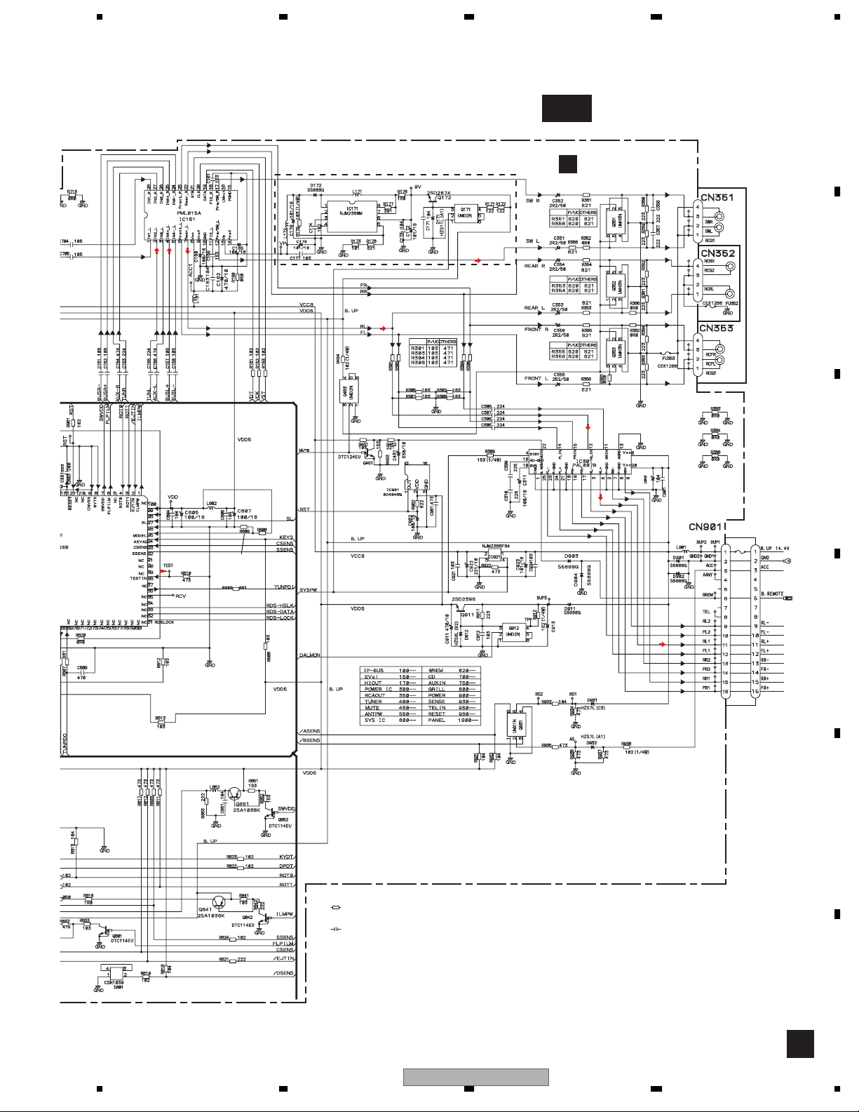
CN351
2
SWL
Q351
CN352
1
RCRL
Q352
CN353
2
RCFL
Q353
VDD5V REG.
BACKUP SENSE
Q931
ACC SENSE
14
12
22
TUN3V REG.
IC 401
Q171
FLIN
RLIN
MUTE
5
Q911
AMP
Q912
VCC VCC
IC 301
PAL007B
STBY
4
ACC
20
B.REM
SYS 8V REG.
NJM2388F84
B.UP
B.UP
6
FL−
FL+
RL−
RL+
IC 921
4
SYSPW
B.UP
B
CN901
FUSE
1
1
10A
3
3
2
2
BREM
FL−
FL+
RL−
RL+
10
10
12
12
9
9
11
11
6
6
23
21
3
5
25
1213
B.UP
SYSPW
BACK UP
ACC
GND
FLFL+
RL-
RL+
B. REM
C
D
VDD5
BSENS
ASENS
VCC8
VDD_3.3V
8
7
6
NJM2885DL1-33
Q172
13
XOUT
X601
15
XIN
Q841
ILMB+
Q802
Q851
8
EJECT
14
FLPILM
12
SWVDD
10
SSENS
9
ROT1
6
ROT0
5
CSENS
13
DPDT
4
KYDT
3
B.UP
Q842
1
ILMPW
2
21
CDRST
EJTIN
FLPILM
SWVDD
SSENS
ROT1
ROT0
CSENS
DPDT
KYDT
DSENS
B.UP
Q801
6
VDD5
Q852
7
92
3
4
93
35
36
S801
18
DSENS
56
D
8
14
12
10
9
6
5
13
4
3
PANEL UNIT
ILMB+
S1901
DGND DGND
EJECT
SWVDD
SSENS
ROT1
ROT0
CSENS CSENS
DPDT
KYDT
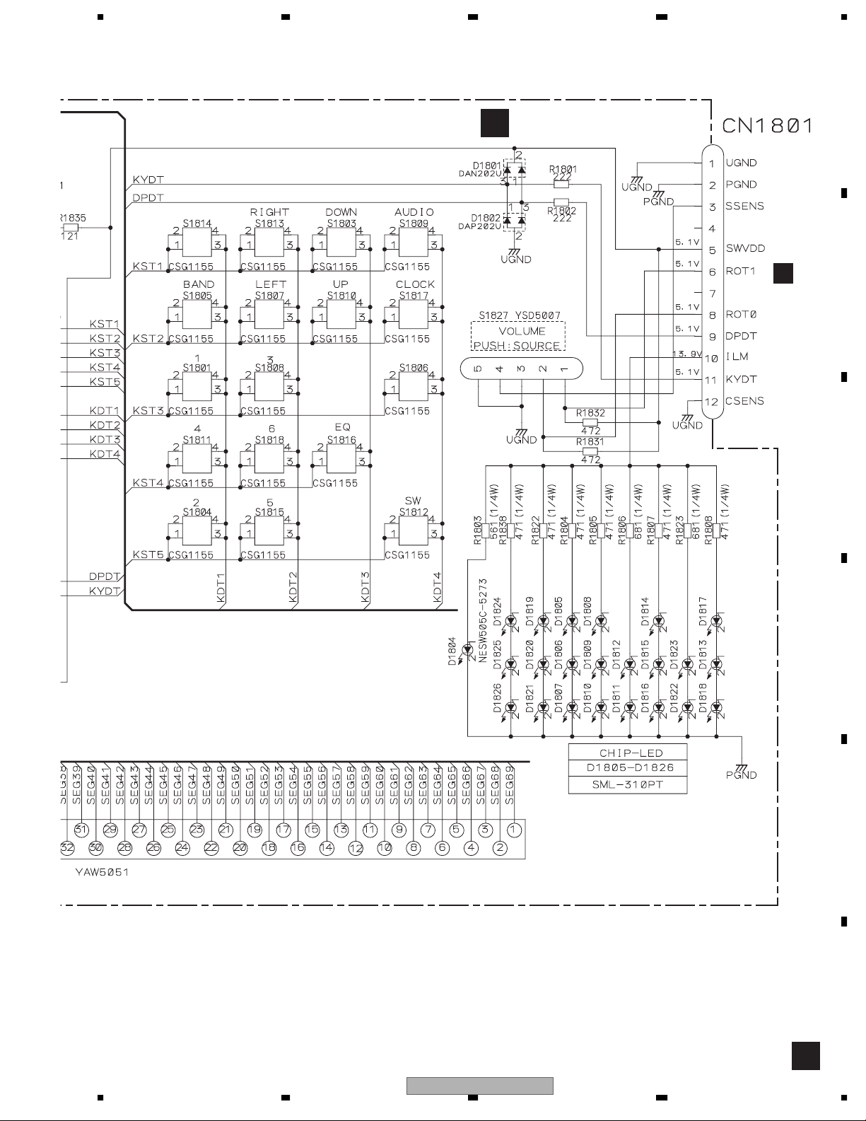
CN1801CN801 CN1902 CN1901
ILM
10
10
11
5
5
3
6
8
12
9
11
SWVDD
S1827
VOLUME
PUSH:SOUCE
SSENS
4
3
ROT1
1
6
ROT0
2
8
12
DPDT
9
KYDT
11
DEH-P480MP/XU/UC
D1804-D1826
SWVDD
S1801
1
S1807
LEFT
S1811
4
S1815
5
REM.CON.
3
IC1802
TSOP4840SB1
50
SI
49
SO
46
V3
47
VDD
7
KEY MATRIX
S1803
S1804
DOWN
S1808
S1812
SW/BB
S1816
1
KEY CONTROLLER
3
EQ
57
REM
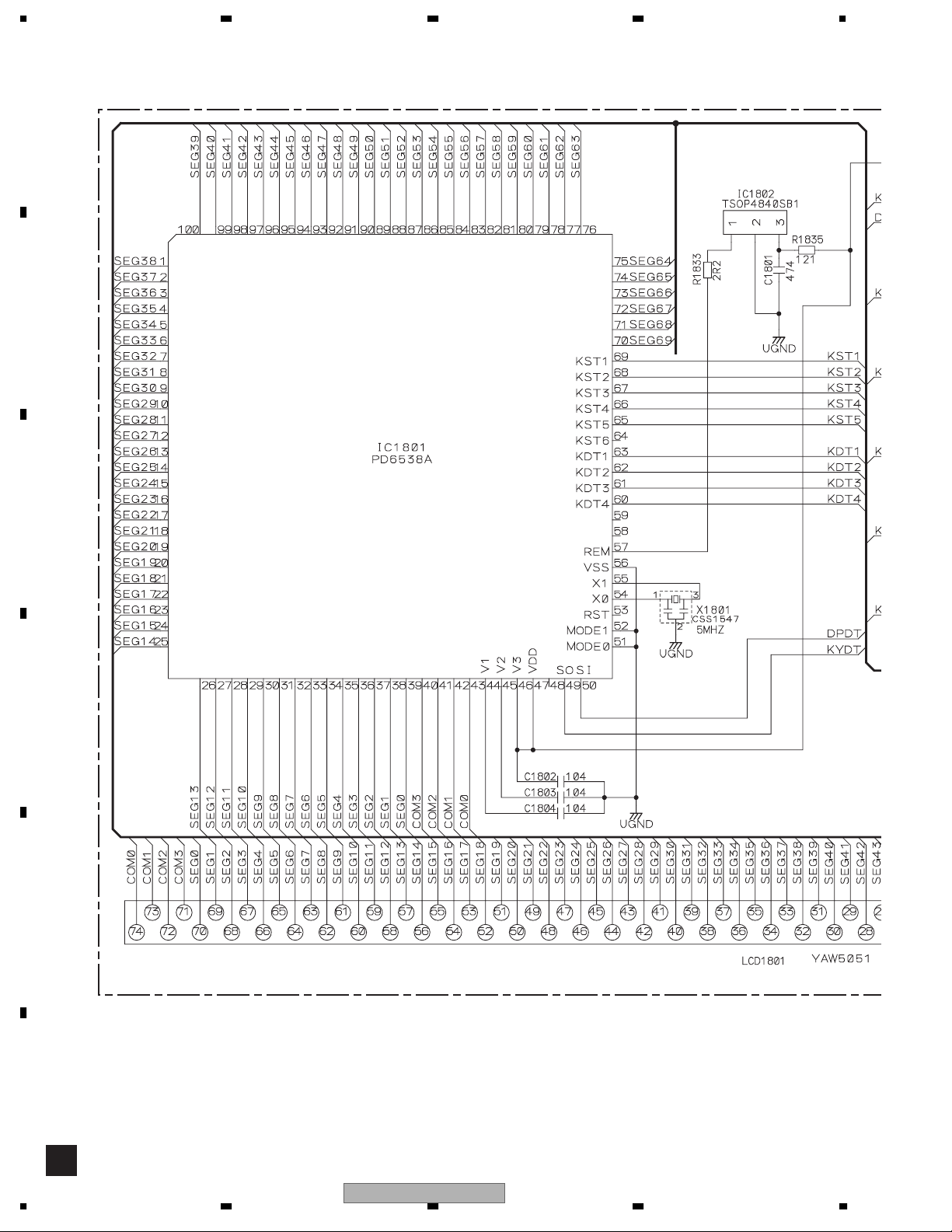
LCD DRIVER/
IC 1801
PD6538A
2
S1809
AUDIO
S1813
RIGTH
S1817
CLOCK
KEY DATA
KEYBOARD UNIT
B
S1805
S1806
BAND
DISP
S1810
UP
S1814
FUNC
S1818
6
54
X0
X1801
5MHz
55
X1
LCD1801
8
E
F
13
A-a
A-b
A-a
A-b
A-b
A-a
1234
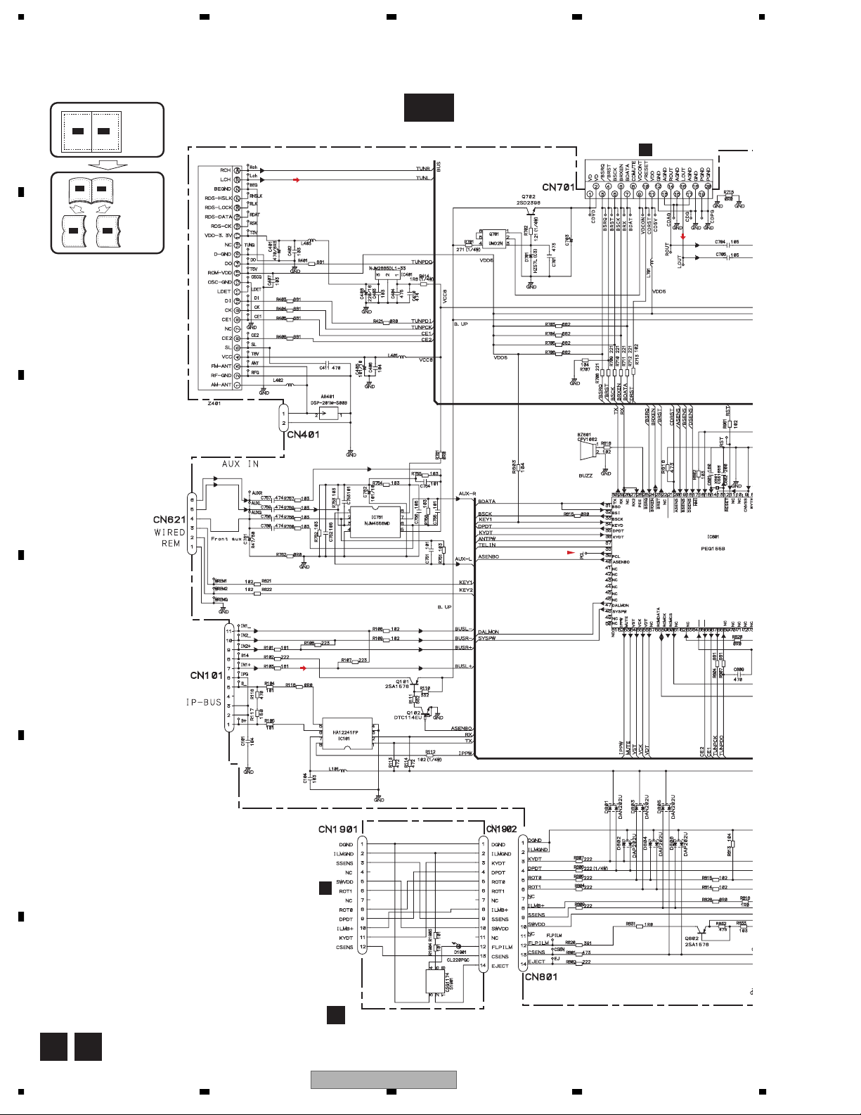
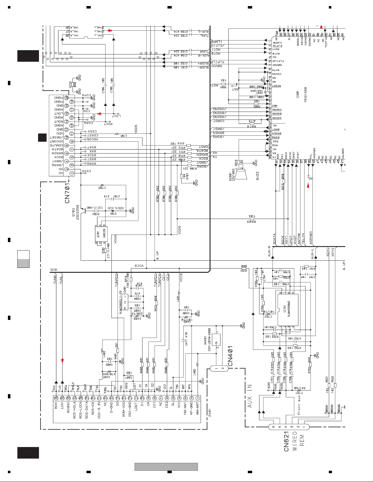
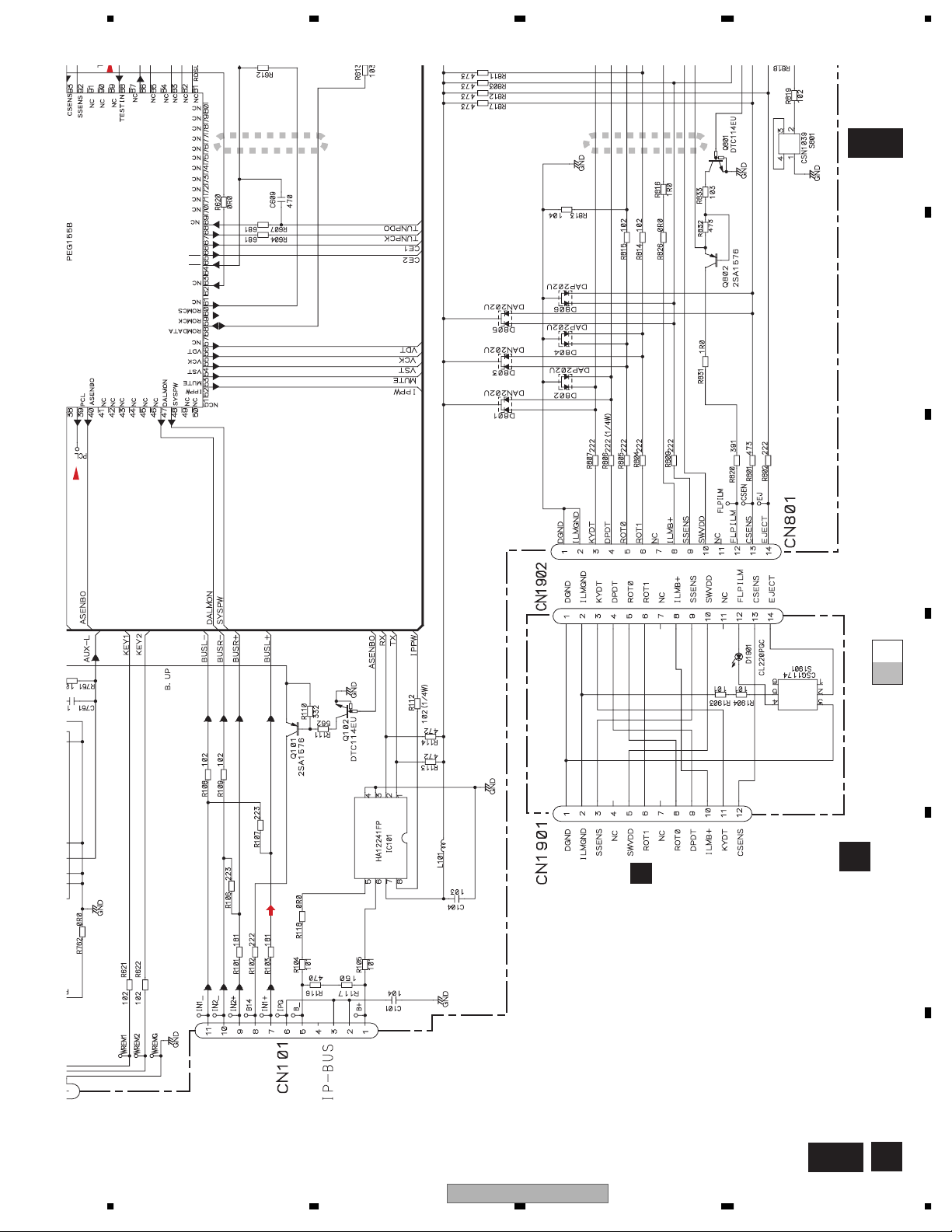
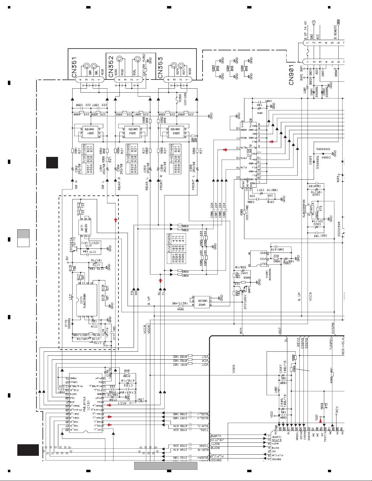
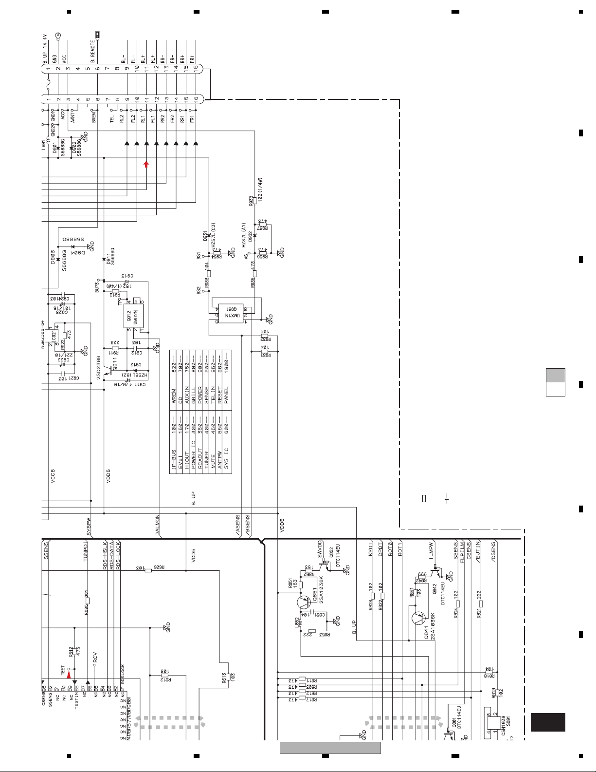
3.2 OVERALL CONNECTION DIAGRAM(GUIDE PAGE)
Note: When ordering service parts, be sure to refer to " EXPLODED VIEWS AND PARTS LIST" or
"ELECTRICAL PARTS LIST".
A
Large size
A-b
A-b
SCH diagram
Guide page
FM:-24dBs
AM:-24dBs
A-a
A-a
A-a
C
CN901
A-b
Detailed page
FM/AM TUNER UNIT
471/16
CD:0.35dBs
15,000MHz
XIN
VSS
VCC
CD-RESET
NC
NC
XOUT
VCC
VSS
CE2
CE1
TUNPCK
TUNPDI
A-a
B
C
D
E
F
A D
14
IP-Bus:2.21dBs
B
CN1801
EJECT
PANEL UNIT
D
DEH-P480MP/XU/UC
1234
,
5678
A
A-b
TUNER AMP UNIT
A
B
>
3A
>
3A
FM,AM:-2.9dBs
CD:10.45dBs
IP-Bus:10.31dBs
P480MP
C
332/16
XOUT
TUNPDI
TUNPDO
AVCC
VREF
AVSS
473:P480MP
104:P4800MP
473:P4800MP
471/16
FM,AM:23.1dBs
CD:36.45dBs
IP-Bus:36.31dBs
600µH
CEK1208 10A
>
D
E
DSENS
NOTE :
Symbol indicates a resistor.
No differentiation is made between chip resistors and
discrete resistors.
Symbol indicates a capacitor.
No differentiation is made between chip capacitors and
discrete capacitors.
The > mark found on some component parts indicates
the importance of the safety factor of the part.
Therefore, when replacing, be sure to use parts of
identical designation.
For resistors and capacitors in the circuit diagrams, their resistance
values or capacitance values are expressed in codes:
Ex. *Resistors
Code Practical value
123 12k ohms
103 10k ohms
*Capacitors
Code Practical value
103 0.01uF
101/10 100uF/10V
DEH-P480MP/XU/UC
56
F
A
7
8
15
1234
AVSS
VREF
A
AVCC
TUNPDO
B
C
A-b
1 2
CD:0.35dBs
CN901
C
471/16
15,000MHz
XOUT
VSS
XIN
VCC
CD-RESET
NC
NC
A-b
A-a
A-a
D
E
FM:-24dBs
AM:-24dBs
FM/AM TUNER UNIT
F
A-a
16
1234
DEH-P480MP/XU/UC
5678
TUNPDO
3 4
TUNPDI
TUNPCK
CE1
CE2
VSS
VCC
NC
A-b
DSENS
A
B
C
IP-Bus:2.21dBs
B
CN1801
EJECT
A-b
A-a
A-a
PANEL UNIT
D
D
E
56
DEH-P480MP/XU/UC
F
A-a
7
8
D
17
1234
A
>
CEK1208 10A
>
3A
600µH
>
3A
332/16
B
TUNER AMP UNIT
A
C
P480MP
A-b
A-a
D
E
473:P4800MP
F
A-b
18
473:P480MP
104:P4800MP
FM,AM:-2.9dBs
CD:10.45dBs
IP-Bus:10.31dBs
AVSS
VREF
AVCC
TUNPDO
1 2
DEH-P480MP/XU/UC
1234
>
5678
A
B
FM,AM:23.1dBs
CD:36.45dBs
471/16
IP-Bus:36.31dBs
For resistors and capacitors in the circuit diagrams, their resistance
values or capacitance values are expressed in codes:
Ex. *Resistors
Code Practical value
123 12k ohms
103 10k ohms
*Capacitors
Code Practical value
103 0.01uF
101/10 100uF/10V
C
A-b
A-a
D
The > mark found on some component parts indicates
the importance of the safety factor of the part.
Therefore, when replacing, be sure to use parts of
Symbol indicates a resistor.
No differentiation is made between chip resistors and
discrete resistors.
Symbol indicates a capacitor.
No differentiation is made between chip capacitors and
discrete capacitors.
NOTE :
identical designation.
E
473:P480MP
104:P4800MP
TUNPDO
3 4
DEH-P480MP/XU/UC
56
F
A-b
DSENS
7
8
19
1234
3.3 KEYBOARD UNIT
A
B
LCD DRIVER / KEY CONTROLLER
C
D
E
F
B
20
1234
DEH-P480MP/XU/UC
5678
A
KEYBOARD UNIT
B
FUNCTION
DISPLAY
D
CN1901
B
C
D
56
DEH-P480MP/XU/UC
E
F
B
7
8
21
1234
NC
3.4 CD MECHANISM MODULE(GUIDE PAGE)
A
C-a
F
T
S
C
F
T
S
C
B
C
PICKUP UNIT(P10.5)(SERVICE)
SWITCHES:
CD CORE UNIT(S10.5COMP1)
S901:HOME SWITCH..........ON-OFF
S903:DSCSNS SWITCH......ON-OFF
S904:12EJ SWITCH.............ON-OFF
S905:8EJ SWITCH...............ON-OFF
$
F
F
T
F
T
F
F
T
T
F
T
T
@
!
The underlined indicates the switch position.
D
NCNCNC
NC
M1 CXC6742
SPINDLE MOTOR
M2 CXC4026
LOADING/CARRIAGE MOTOR
S
S
C
C
T
F
CD DRIVER
#
S
8
9
6
C
7
4
E
3
2
1
F
F
T
T
S
S
C
C
NC
NC
NC
NC
NC
NC
NC
NC
NC
NC
NC
NC
NC
NC
NC
NC
F
C
22
1234
DEH-P480MP/XU/UC
5678
A
C-b
SIGNAL LINE
F
FOCUS SERVO LINE
T
TRACKING SERVO LINE
C
CARRIAGE SERVO LINE
S
SPINDLE SERVO LINE
CD CORE UNIT(S10.5COMP1)
0
C
Decimal points for resistor
and capacitor fixed values
are expressed as :
←
2.2 2R2
←
0.022 R022
B
+ 3.3 V REGULATOR
C
D
NC
NC
NCNCNCNCNC
NC
NC
NC
NC
NC
NC
NC
NC
NC
NC
NC
NC
NC
NC
NC
NC
NCNCNCNCNC
CD CONTROLLER
CD CONTROLLER
CD3VON(MCKRQ)
SRAMLEVEL2
ADENA
SRAMLEVEL1
SRAMLEVEL0
(S904)
(S905)
5
E
NC
DEH-P480MP/XU/UC
56
^
%
CN701
A
F
C
7
8
23
 Loading...