

Pioneer DEH-1300-R, DEH-1310, DEH-1330-R Service manual
PIONEER CORPORATION 4-1, Meguro 1-Chome, Meguro-ku, Tokyo 153-8654, Japan
PIONEER ELECTRONICS SERVICE INC. P.O.Box 1760, Long Beach, CA 90801-1760 U.S.A.
PIONEER EUROPE NV Haven 1087 Keetberglaan 1, 9120 Melsele, Belgium
PIONEER ELECTRONICS ASIACENTRE PTE.LTD. 253 Alexandra Road, #04-01, Singapore 159936
C PIONEER CORPORATION 2000
K-ZZA. OCT. 2000 Printed in Japan
ORDER NO.
CRT2558
HIGH POWER CD PLAYER WITH RDS TUNER
DEH-1330R X1M/EW
CONTENTS
1. SAFETY INFORMATION ............................................3
2. EXPLODED VIEWS AND PARTS LIST.......................4
3. BLOCK DIAGRAM AND SCHEMATIC DIAGRAM ...12
4. PCB CONNECTION DIAGRAM ................................34
5. ELECTRICAL PARTS LIST ........................................42
6. ADJUSTMENT..........................................................48
7. GENERAL INFORMATION .......................................52
7.1 DIAGNOSIS ........................................................52
7.1.1 TEST MODE ..............................................52
7.1.2 DISASSEMBLY .........................................55
7.1.3 CONNECTOR FUNCTION DESCRIPTION .......59
7.2 PARTS .................................................................60
7.2.1 IC................................................................60
7.2.2 DISPLAY....................................................66
7.3 OPERATIONAL FLOW CHART...........................68
8. OPERATIONS AND SPECIFICATIONS.....................69
DEH-1300R X1M/EW
DEH-1310 X1M/EE
DEH-1330R/X1M/EW
- This service manual should be used together with the following manual(s):
Model No. Order No. Mech. Module Remarks
CX-958 CRT2423 S8.1 CD Mech. Module:Circuit Description, Mech.Description, Disassembly

2
DEH-1330R,1300R,1310
- CD Player Service Precautions
1. For pickup unit(CXX1285) handling, please refer
to"Disassembly"(see page 55).
During replacement, handling precautions shall be
taken to prevent an electrostatic discharge(protection
by a short pin).
2. During disassembly, be sure to turn the power off
since an internal IC might be destroyed when a con-
nector is plugged or unplugged.
3. Please checking the grating after changing the ser-
vice pickup unit(see page 50).
3
DEH-1330R,1300R,1310
1. SAFETY INFORMATION
This service manual is intended for qualified service technicians; it is not meant for the casual do-it-yourselfer.
Qualified technicians have the necessary test equipment and tools, and have been trained to properly and safely repair
complex products such as those covered by this manual.
Improperly performed repairs can adversely affect the safety and reliability of the product and may void the warranty.
If you are not qualified to perform the repair of this product properly and safely; you should not risk trying to do so
and refer the repair to a qualified service technician.
1. Safety Precautions for those who Service this Unit.
• When checking or adjusting the emitting power of the laser diode exercise caution in order to get safe, reliable
results.
Caution:
1. During repair or tests, minimum distance of 13cm from the focus lens must be kept.
2. During repair or tests, do not view laser beam for 10 seconds or longer.
2. A “CLASS 1 LASER PRODUCT” label is affixed to the
bottom of the player.
3. The triangular label is attached to the mechanism
unit frame.
4. Specifications of Laser Diode
Specifications of laser radiation fields to which human access is possible during service.
Wavelength = 800 nanometers
CLASS 1
LASER PRODUCT
4
DEH-1330R,1300R,1310
1 Cord Assy See Contrast table(2)
2 Screw CBA1002
3 Handle CNC5395
4 Bush CNV3930
* 5 Polyethylene Bag E36-615
6 Polyethylene Bag CEG-162
7-1 •••••
7-2 Owner's Manual
See Contrast table(2)
7-3 Owner's Manual See Contrast table(2)
7-4 Installation Manual
See Contrast table(2)
* 7-5 Passport See Contrast table(2)
* 7-6 Warranty Card CRY1157
8 Carton
See Contrast table(2)
9 Contain Box See Contrast table(2)
10 Protector CHP2346
11 Protector CHP2347
12 Case Assy CXB3520
Mark No. Description Part No. Mark No. Description Part No.
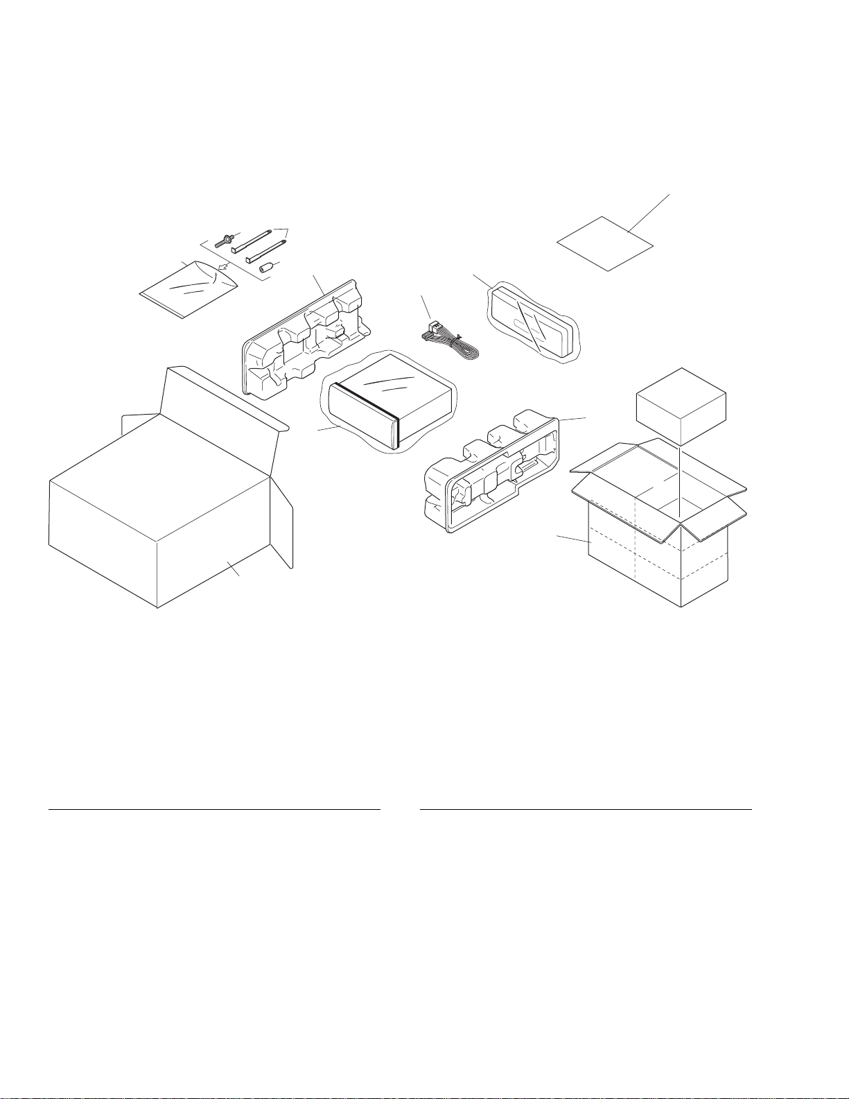
(1) PACKING SECTION PARTS LIST
NOTE:
- Parts marked by “*” are generally unavailable because they are not in our Master Spare Parts List.
- Screws adjacent to ∇ mark on the product are used for disassembly.
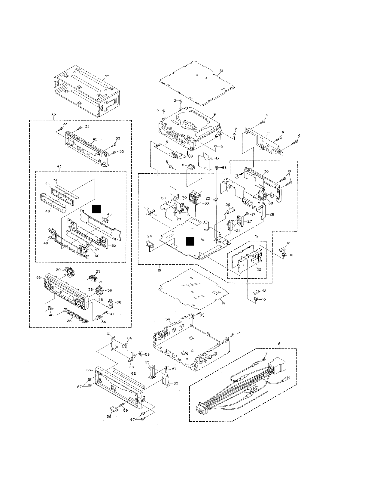
2. EXPLODED VIEWS AND PARTS LIST
2.1 PACKING
10
1
12
6
8
9
11
7
4
3
5
2
5
DEH-1330R,1300R,1310
Part No.
Mark No. Symbol and Description DEH-1330R/X1M/EW DEH-1300R/X1M/EW DEH-1310/X1M/EE
1 Cord Assy CDE6467 CDE6467 CDE6470
7-2 Owner's Manual CRD3276 CRD3276 CRD3284
7-3 Owner's Manual CRD3277 CRD3277 Not used
7-4 Installation Manual CRD3278 CRD3278 CRD3285
* 7-5 Passport CRY1013 CRY1013 Not used
8 Carton CHG4159 CHG4158 CHG4156
9 Contain Box CHL4159 CHL4158 CHL4156
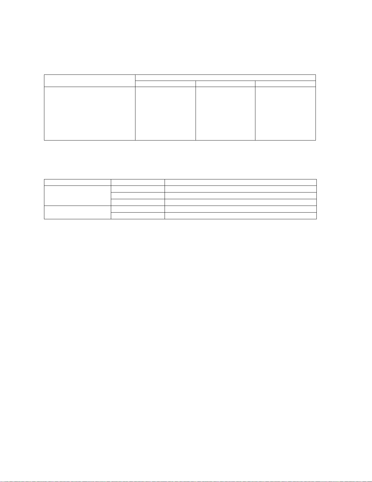
(2) CONTRAST TABLE
DEH-1330R/X1M/EW, DEH-1300R/X1M/EW and DEH-1310/X1M/EE are constructed the same except for
the following:
- Owner's Manual, Installation Manual
Model Part No. Language
DEH-1330R/X1M/EW CRD3276 English, Spanish, German
DEH-1300R/X1M/EW CRD3277 French, Italian, Dutch
CRD3278 English, Spanish, German, French, Italian, Dutch
DEH-1310/X1M/EE CRD3284 English, Russian
CRD3285 English, Russian
6
DEH-1330R,1300R,1310
2.2 EXTERIOR(DEH-1330R/X1M/EW, DEH-1300R/X1M/EW)
B
A

7
DEH-1330R,1300R,1310
1 •••••
2 Screw BSZ26P060FMC
3 Screw BSZ30P060FMC
4 Screw BSZ30P120FMC
5 Cable CDE6160
6 Cord Assy CDE6467
7 Cap CKX-003
8 Fuse(10A) CEK1136
9
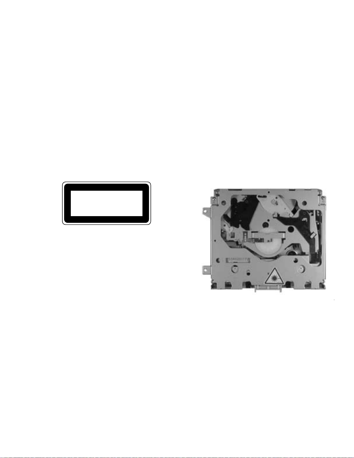
CD Mechanism Module(S8.1) CXK5203
10 Holder CNC5704
11 Cover CNC9127
12 Cushion CNM5210
13 Insulator CNM6224
14 Insulator CNM6386
15 Tuner Amp Unit CWM7294
16 Screw ASZ26P080FMC
17 Screw BPZ26P080FMC
18 Screw BSZ26P160FMC
19 FM/AM Tuner Unit CWE1562
20 Holder CNC8815
21 Pin Jack(CN301) CKB1041
22 Terminal(CN403) CKF1059
23 Plug(CN901) CKM1330
24 Connector(CN601) CKS3581
25 Connector(CN605) CKS3838
26 Antenna Jack(CN402) CKX1056
27 Holder CNC8041
28 Holder CNC8043
29 Holder CNC9128
30 Heat Sink CNR1589
31 Case Unit CXB4033
32 Detach Grille Assy
See Contrast table(2)
33 Screw BPZ20P100FZK
34 Button(DETACH)
See Contrast table(2)
35 Button(1-6, CLK) CAC6822
36 Button(A, B) CAC6823
37 Button(EJECT/BSM) CAC6824
38 Button(CROSS) CAC6825
39 Button(+/-, EQ, LD) CAC6834
40 Button(SOURCE) CAC6851
41 Spring CBH2210
42 Cover
See Contrast table(2)
43 Keyboard Unit See Contrast table(2)
44 LCD CAW1632
45 Connector(CN1801) CKS3580
46 Holder CNC9078
47 Sheet CNM7057
48 •••••
49 Lighting Conductor CNV6475
50 Lighting Conductor CNV6476
51 Rubber CNV6477
52 Rubber CNV6478
53 Grille Unit
See Contrast table(2)
54 Chassis Unit
See Contrast table(2)
55 Holder Unit CXB6681
56 Button CAC4836
57 Spring CBH1835
58 Spring CBH2208
59 Spring CBH2367
60 Bracket CNC6791
61 Holder CNC8042
62 Cover CNM6276
63 Panel
See Contrast table(2)
64 Arm CNV4692
65 Arm CNV4728
66 Arm CNV5576
67 Screw IMS20P030FZK
68 Screw ISS26P055FUC
69 IC(IC302) TDA7386
70 Transistor(Q904, 981) 2SD2396
(1) EXTERIOR SECTION PARTS LIST
Mark No. Description Part No. Mark No. Description Part No.
Part No.
Mark No. Symbol and Description DEH-1330R/X1M/EW DEH-1300R/X1M/EW
32 Detach Grille Assy CXB6148 CXB6147
34 Button(DETACH) CAC5929 CAC5789
42 Cover CNS6383 CNS6114
43 Keyboard Unit CWM7306 CWM7305
53 Grille Unit CXB7184 CXB7183
54 Chassis Unit CXB6658 CXB6657
63 Panel CNS6385 CNS6345
(2) CONTRAST TABLE
DEH-1330R/X1M/EW and DEH-1300R/X1M/EW are constructed the same except for the following:
8
DEH-1330R,1300R,1310
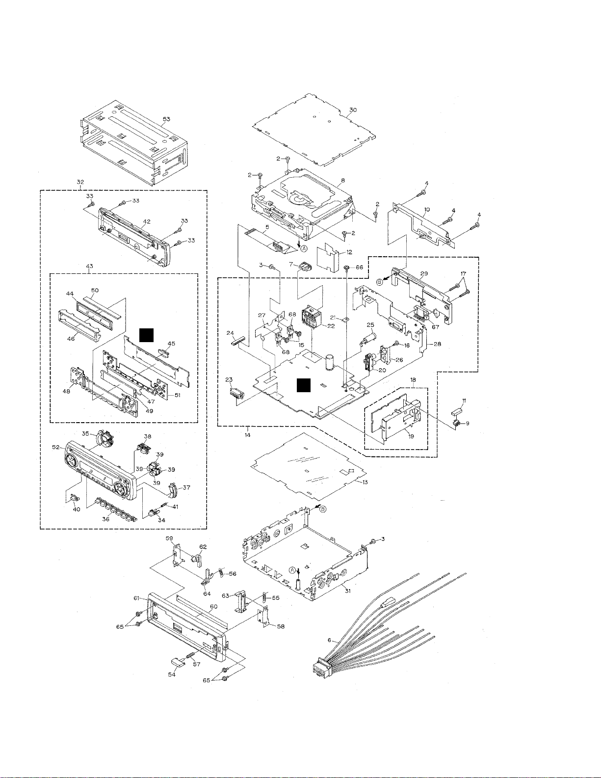
2.3 EXTERIOR(DEH-1310/X1M/EE)
B
A

9
DEH-1330R,1300R,1310
1 •••••
2 Screw BSZ26P060FMC
3 Screw BSZ30P060FMC
4 Screw BSZ30P120FMC
5 Cable CDE6160
6 Cord Assy CDE6470
7 Fuse(10A) CEK1136
8
CD Mechanism Module(S8.1) CXK5203
9 Holder CNC5704
10 Cover CNC9127
11 Cushion CNM5210
12 Insulator CNM6224
13 Insulator CNM6386
14 Tuner Amp Unit CWM7295
15 Screw ASZ26P080FMC
16 Screw BPZ26P080FMC
17 Screw BSZ26P160FMC
18 FM/AM Tuner Unit CWE1566
19 Holder CNC8815
20 Pin Jack(CN301) CKB1041
21 Terminal(CN403) CKF1059
22 Plug(CN901) CKM1330
23 Connector(CN601) CKS3581
24 Connector(CN605) CKS3838
25 Antenna Jack(CN402) CKX1056
26 Holder CNC8041
27 Holder CNC8043
28 Holder CNC9128
29 Heat Sink CNR1589
30 Case Unit CXB4033
31 Chassis Unit CXB4625
32 Detach Grille Assy CXB6149
33 Screw BPZ20P100FZK
34 Button(DETACH) CAC5789
35 Button(+/-, EQ, LD) CAC6821
36 Button(1-6, CLK) CAC6822
37 Button(A, B) CAC6823
38 Button(EJECT/BSM) CAC6824
39 Button(CROSS) CAC6825
40 Button(SOURCE) CAC6851
41 Spring CBH2210
42 Cover CNS6114
43 Keyboard Unit CWM7307
44 LCD CAW1633
45 Connector(CN1801) CKS3580
46 Holder CNC9078
47 Sheet CNM7057
48 Lighting Conductor CNV6475
49 Lighting Conductor CNV6476
50 Rubber CNV6477
51 Rubber CNV6478
52 Grille Unit CXB7185
53 Holder Unit CXB6681
54 Button CAC4836
55 Spring CBH1835
56 Spring CBH2208
57 Spring CBH2367
58 Bracket CNC6791
59 Holder CNC8042
60 Cover CNM6276
61 Panel CNS6345
62 Arm CNV4692
63 Arm CNV4728
64 Arm CNV5576
65 Screw IMS20P030FZK
66 Screw ISS26P055FUC
67 IC(IC302) TDA7386
68 Transistor(Q904, 981) 2SD2396
- EXTERIOR SECTION PARTS LIST
Mark No. Description Part No.
Mark No. Description Part No.
10
DEH-1330R,1300R,1310
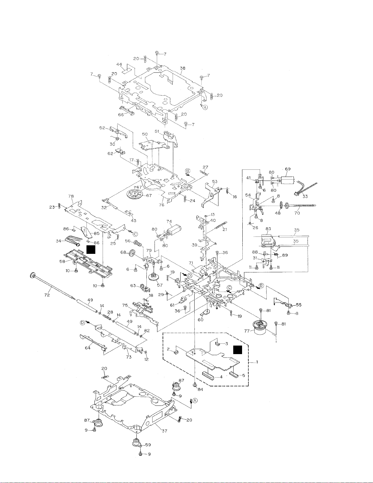
2.4 CD MECHANISM MODULE
C
D

11
DEH-1330R,1300R,1310
Mark No. Description Part No. Mark No. Description Part No.
1 Control Unit CWX2411
2 Connector(CN802) CKS2192
3 Connector(CN801) CKS2193
4 Connector(CN701) CKS2773
5 Connector(CN101) CKS3486
6 Screw BMZ20P030FMC
7 Screw BSZ20P040FMC
8 Screw(M2x3) CBA1077
9 Screw(M2x5) EBA1028
10 Screw CBA1243
11 Screw(M2x4) CBA1362
12 Washer CBF1037
13 Washer CBF1038
14 Washer CBF1060
15 •••••
16 Spring CBH2079
17 Spring CBH2117
18 Spring CBH2314
19 Spring CBH2110
20 Spring CBH2282
21 Spring CBH2318
22 •••••
23 Spring CBH2324
24 Spring CBH2118
25 Spring CBH2161
26 Spring CBH2163
27 Spring CBH2189
28 Spring CBH2377
29 Spring CBH2260
30 Spring CBH2262
31 Bracket CNC8568
32 Spring CBL1369
33 Connector CDE5531
34 Connector CDE5532
35 Shaft CLA3894
36 Screw(M2.6x6) CBA1458
37 Frame CNC8565
38 Frame CNC8749
39 Lever CNC9265
40 Arm CNC8663
41 Bracket CNC8567
42 •••••
43 Spacer CNM3315
44 Sheet CNM6659
45 •••••
46 •••••
47 Ball CNR1189
48 Belt CNT1086
49 Roller CNV4509
50 Arm CNV6037
51 Arm CNV5247
52 Arm CNV5248
53 Arm CNV5249
54 Guide CNV5254
55 Guide CNV5255
56 Gear CNV5257
57 Gear CNV5256
58 Guide CNV6272
59 Damper CNV6174
60 Arm CNV6096
61 Arm CNV6031
62 Arm CNV6211
63 Guide CNV6012
64 Guide CNV5510
65 •••••
66 Guide CNV5751
67 Clamper CNV6013
68 Gear CNV5813
69 Motor Unit(M1) CXB2190
70 Screw Unit CXB5892
71 Chassis Unit CXB4797
72 Gear Unit CXB4728
73 Arm Unit CXB5753
74 Motor Unit(M2) CXB2195
75 Lever Unit CXB4730
76 Arm Unit CXB4731
77 Motor Unit(M3) CXB2562
78 Arm Unit CXB4732
79 Bracket Unit CXB4795
80 Screw JFZ20P025FMC
81 Screw JGZ17P025FZK
82 Washer YE20FUC
83 Pickup Unit(Service)(P8) CXX1285
84 Screw IMS26P030FMC
* 85 PCB CNX2982
86 Photo-transistor(Q1, 2) CPT230SX-TU
87 Damper CNV6175
88 Rack CNV6014
89 Spring CBH2315
- CD MECHANISM MODULE SECTION PARTS LIST
12
DEH-1330R,1300R,1310
1
23
4
1
234
D
C
B
A
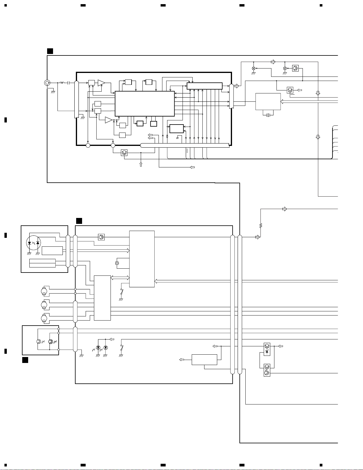
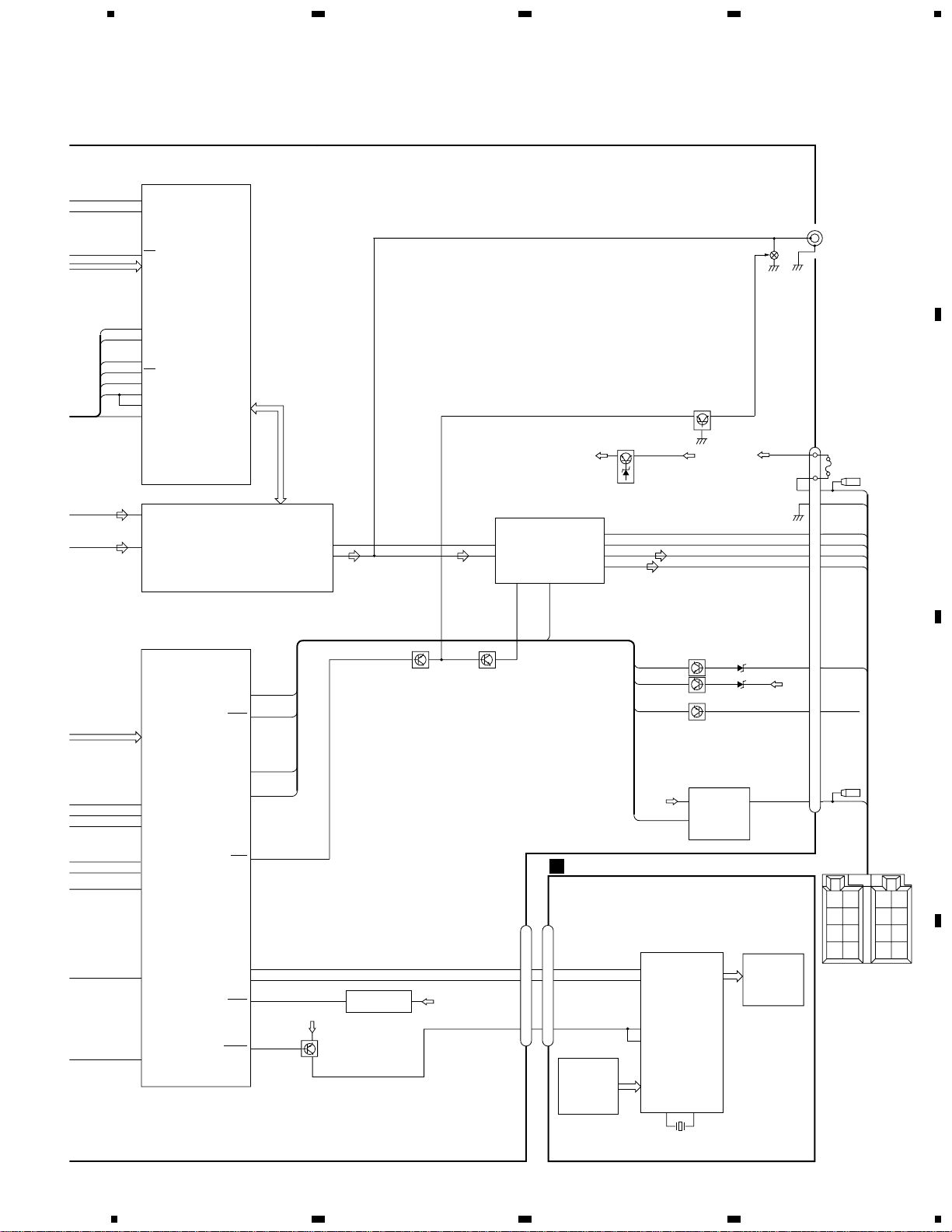
3. BLOCK DIAGRAM AND SCHEMATIC DIAGRAM
3.1 BLOCK DIAGRAM
M
M
M
LD
MD
HOLOGRAM
UNIT
FOCUS ACT
TRACKING ACT
LD+
MD
FO+
TO+
14
5
4
3
SPINDLE
MOTOR
CARRIAGE
MOTOR
LOADING
MOTOR
1
2
3
4
3
1
2
SELECT
SENSE
DISC SENSE
D
CN801
CN802
D802 D801
VD
S802
CLAMP
6
5
11
22
23
21
1
28
21
CDLOAD
CDEJET
CONT
EJTSNS
DSCSNS
CLAMP
CD5VON
VDCONT
VDD
IC 701
BA05SFP
IN
+5V REGULATOR
24
1
VD
Q981
Q982
B.U
ANTENNA
CN402
A
LOCL
Q411
VCC
VDD
PCE2
PCK
PCE1
SL
SD
PDIO
C
Q101
CN101
FOP
TOP
A+C/F
B+D/E
98
LD L_OUT
PD
HOME
97
24
23
39
X201
TD/FD
SD/MD
RF-AMP, DSP,
SERVO, DAC
IC 201
UPD63711GC
16
CN701 CN605
1718
24
CDL
IC 301
BA5985FM
S801
HOME
12
16
18
11
14
13
10
9
SOP
TOP
FOP
SOM
COP
COM
LOP
LOM
FWD
REV
MUTE
CD DRIVER
718
19
20
14
3
2
4
CLAMP
DINC
EJTD
CDLOAD
EJET
CONT
PDIO
TUNER AMP UNIT
CONTROL UNIT
PICKUP UNIT(SERVICE)(P8)
PHOTO UNIT(S8)
4
VD
CD5VON
IC 3
EEPROM
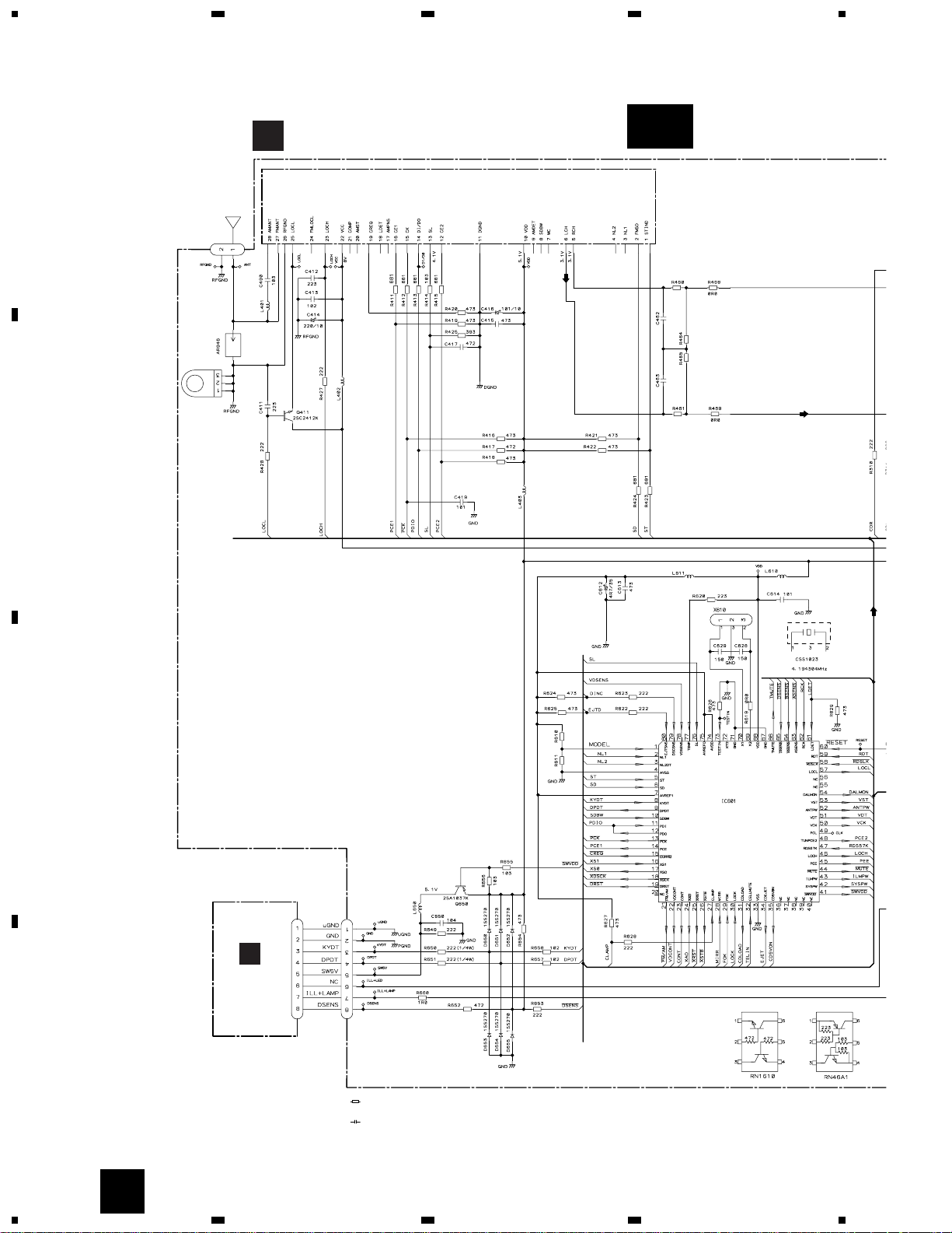
FM/AM TUNER UNIT
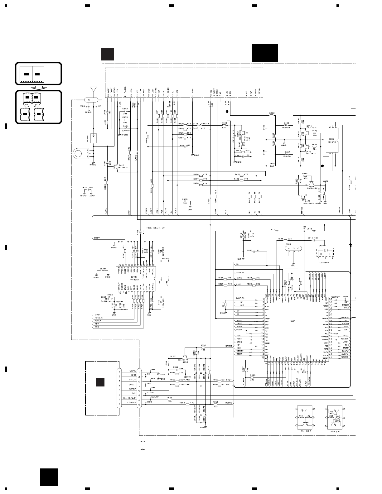
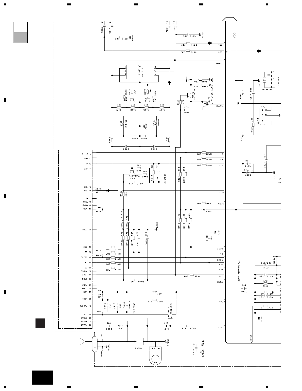
28
27
FM/AM 1ST IF 10.7MHz
T51 Q51 CF51
CF52 CF53
IC1
MIXER, IF AMP, DET.
6
21
18
LDET
COMP
222510 14 12 15 16 8 13 2 3 4
CF202
VDD
VCC
DI/DO
CE2CKCE1
SDBWSLFMSD
NL1
NL2
IC 2 FM MPX
AMANT
FMANT
ATT
ATT
AMRF
FMRF
IMG ADJ
RF ADJ
X901
10.25MHz
ANT ADJ
LOCL
23
LOCH
AMDET
MPXREF 41kHz
AM 2ND IF
450kHz
19
CREQ
11
DGND
1
STIND
L ch
5
R ch
924
NC
FMLOCL
20177
NCNCWC
26
RFGND
Q472 Q475
Q476
RDS
DECODER
IC 701
PM4009A
20
11 12
X702
Q477
VDD
TMUTE
FM/AM
LDET
13
DEH-1330R,1300R,1310
5
6
78
5
6
7
8
D
C
B
A
KYDT
DPDT
KEY CONT.
LCD DRIVER
IC 1801
PD6340A
3
4
5
3
4
5
KEY MATRIX
SD
SL
PCE
PCK
TUNPCE2
PDO
LOCL
IN2_L
IN3_L
6
76
14
13
48
12
57
2
3
SYSTEM
CONTROLLER
IC 601(1/2)
PE5195A
VST
VCK
VDT
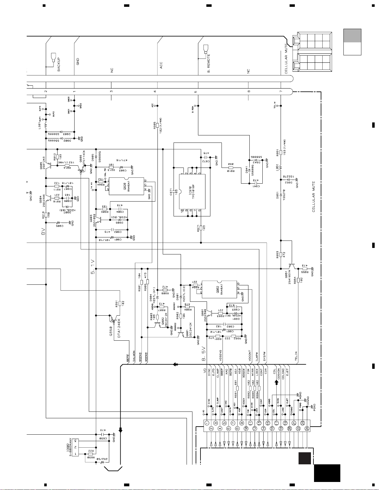
B.U
VDD
Q903
B.U
BACKUP
FL—
FL+
RL—
RL+
ACC
2
1
9
11
10
12
4
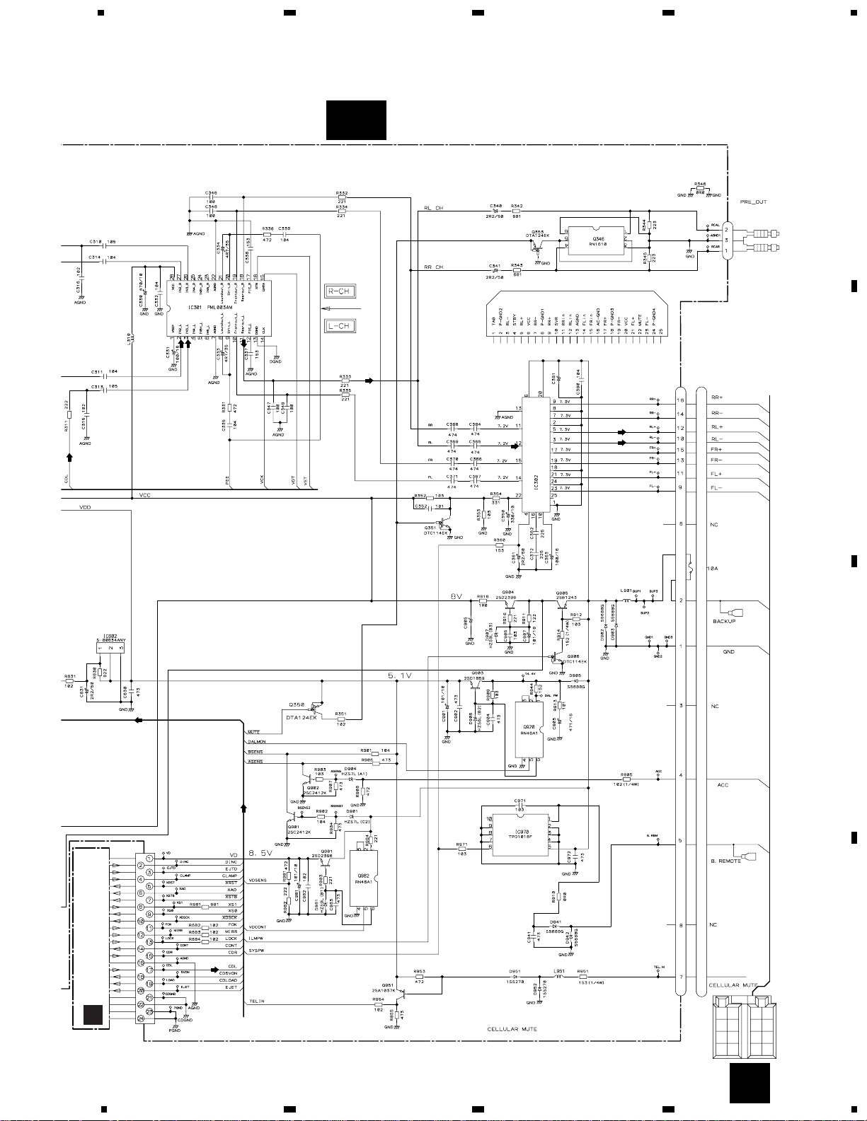
E.VOL
FIE/EQ
IC 301
PML003AM
SYSTEM
CONTROLLER
IC 601(2/2)
PE5195A
ASENS
63
BSENS
64
CELLMUTE
32
SYSPW
42
MUTE
44
KYDT
8
DPDT
9
RESET
60
SWVDD
41
Frontout_L
10
Rearout_L
11
POWER AMP
IC 302
TDA7386
14
12
22 4
5
3
21
23
FL
MUTE STBY
RL
B.U
bsens
asens
Q902
Q351 MUTE
Q350
B
KEYBOARD UNIT
CN1801
CN601
LCD
22 23
X1801
20
18
Q650
RESET
IC 602
S—80834ANY
VDD
12
SYSPW
GND
B.U
SYSPW
5
B.REM
FUSE
10A
CD5VON
31
34
23
80
79
27
22
35
VDCONT
CLAMP
DSCSNS
EJTSNS
CDLOAD
CDEJET
CONT
PDI
11
PDIO
VST/ VCK/ VDT
Q901
VDD
VDD
VLCD
56
10
CN901
IC970
TPD1018F
POWER SWITCH
5
6
1
Q346
CN301
REAR L CH
Q363
RR
+
RR
FR
+
FR
FL
+
FL
RL
+
RL
-
ACC
GND
BACK
UP
BACK UP
FL–
FL+
RL–
RL+
B.REM
ACC
GND
B.
REM
CELLULAR
MUTE
7
TELIN
Q951
CELLULAR MUTE
TELIN
66
61
21
FM/AM
LDET
TMUTE
14
DEH-1330R,1300R,1310
1
23
4
1
234
D
C
B
A
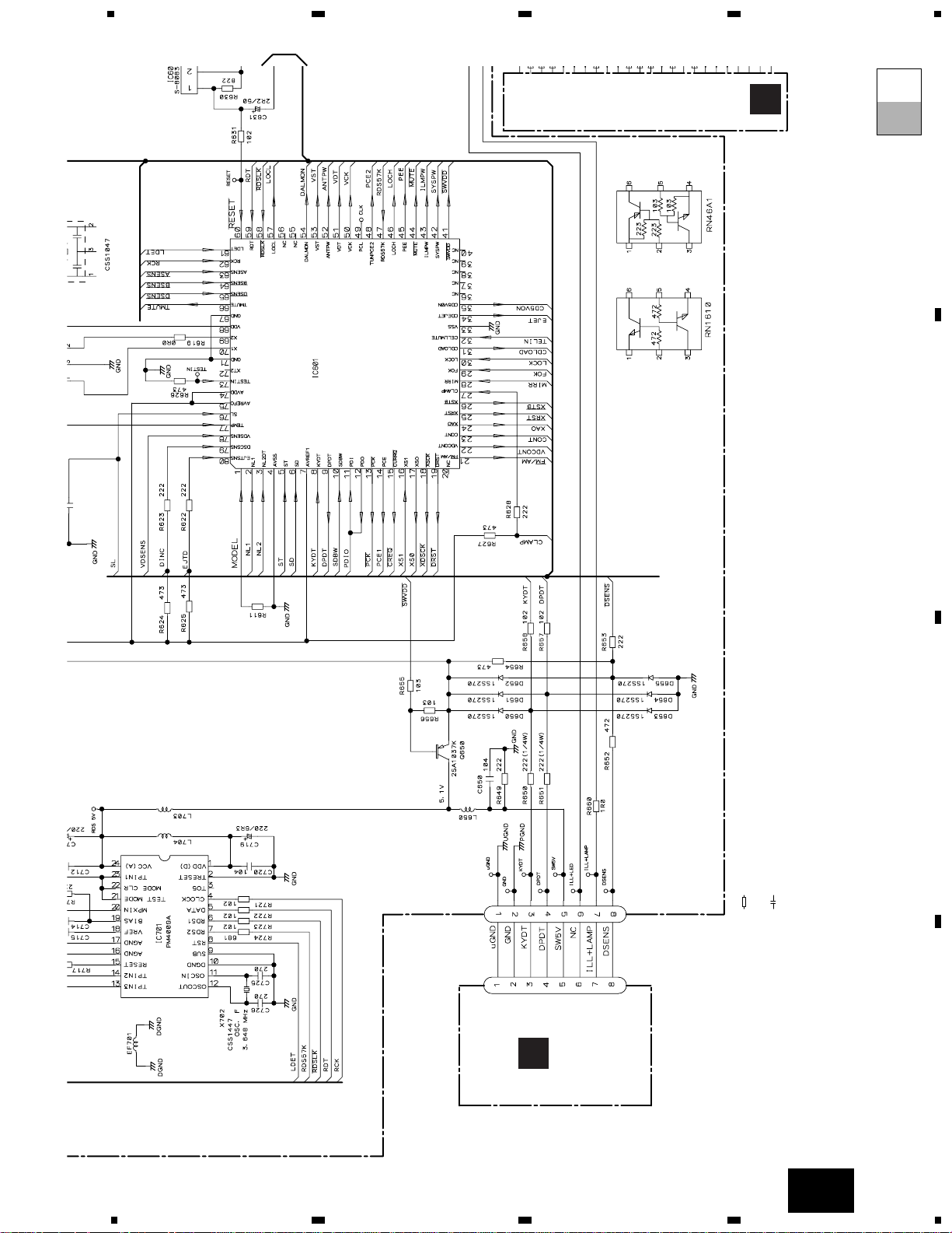
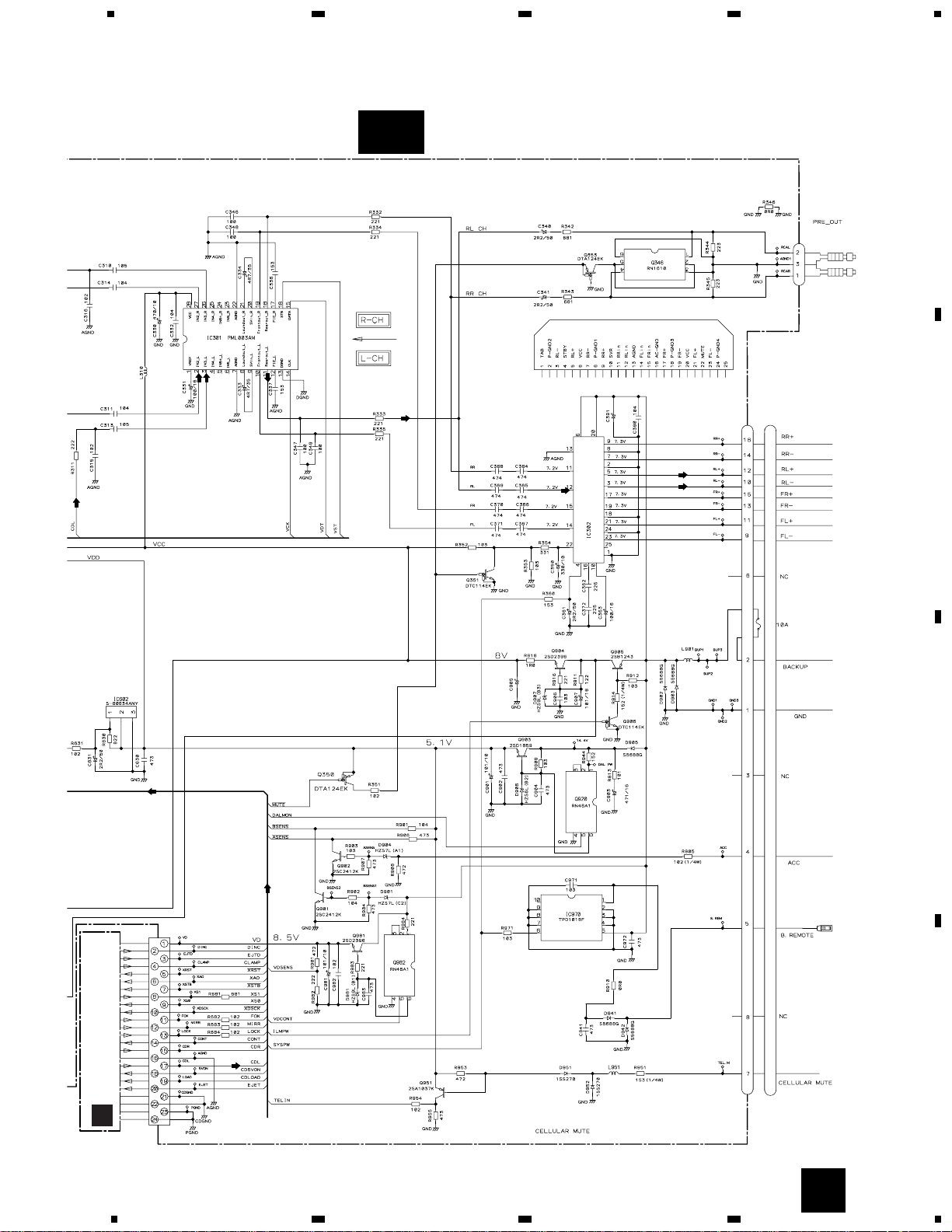
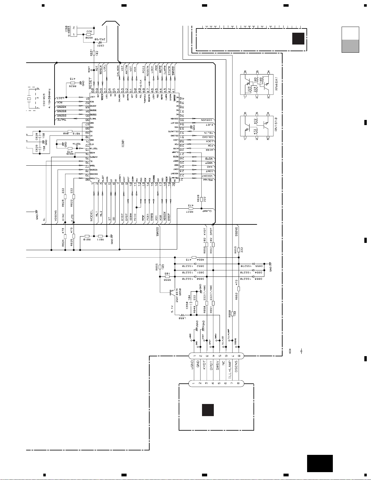
3.2 OVERALL CONNECTION DIAGRAM(GUIDE PAGE)
(DEH-1330R/X1M/EW, DEH-1300R/X1M/EW)
Note: When ordering service parts, be sure to refer to “EXPLODED VIEWS AND PARTS LIST” or “ELECTRICAL PARTS
LIST”.
A-a
A-b
A-b
A-a
A
DSP-201M-S00B
123
272 272
123
162
162
473
4.194MHz
PE5195A
CN601
CN403
CN402
FM(100%):-15.5dBs
AM(30%):-26dBs
SYSTEM CONTROLLER
For resistors and capacitors in the circuit diagrams, their resistance values or
capacitance values are expressed in codes:
Ex. *Resistors
Code Practical value
123 12k ohms
103 10k ohms
*Capacitors
Code Practical value
103 0.01µF
101/10 100µF/10V
The > mark found on some component parts indicates
the importance of the safety factor of the part.
Therefore, when replacing, be sure to use parts of
identical designation.
Symbol indicates a resistor.
No differentiation is made between chip resistors and
discrete resistors.
NOTE :
Symbol indicates a capacitor.
No differentiation is made between chip capacitors and
discrete capacitors.
KEYBOARD
UNIT
B
FM/AM TUNER UNIT
A-a
TUNER AMP UNIT
A
A-a A-b
A-a
A-a
A-b
A-b
Large size
SCH diagram
Guide page
Detailed page
15
DEH-1330R,1300R,1310
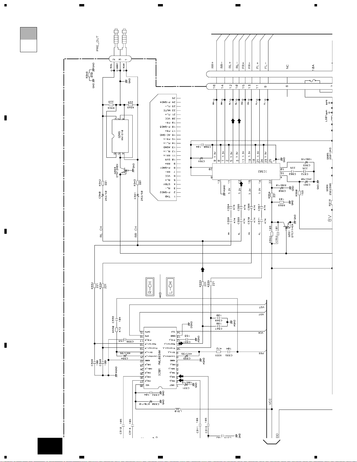
5
6
78
5
6
7
8
D
C
B
A
A
332/16
NC
TDA7386
600µH
331/16
CN901
CN301
CN605
CEK1136
>
FM(100%):+6.6dBs
AM(30%):-2.9dBs
CD:+10.2dBs
FM(100%):+32.6dBs
AM(30%):+23.1dBs
CD:+36.2dBs
CD:+4.1dBs
CD:+9.4dBs
RESET
E.VOL
FIE/EQ
POWER AMP
A.SENS
B.SENS
CONTROL UNIT
C
RR
+
RR
FR
+
FR
FL
+
FL
RL
+
RL
-
ACC
GND
B.
REM
BACK
UP
A-b
16
DEH-1330R,1300R,1310
1
23
4
1
234
D
C
B
A
A-a
A-a
A-b
1
DSP-201M-S00B
123
272 272
123
162
162
CN403
CN402
FM(100%):-15.5dBs
AM(30%):-26dBs
FM/AM TUNER UNIT
TUNER AMP UNIT
A
17
DEH-1330R,1300R,1310
5
6
78
5
6
7
8
D
C
B
A
A-a
A-a
A-b
473
4.194MHz
PE5195A
CN601
SYSTEM CONTROLLER
RESE
For resistors and capacitors in the circuit diagrams, their resistance values or
capacitance values are expressed in codes:
Ex. *Resistors
Code Practical value
123 12k ohms
103 10k ohms
*Capacitors
Code Practical value
103 0.01µF
101/10 100µF/10V
The > mark found on some component parts indicates
the importance of the safety factor of the part.
Therefore, when replacing, be sure to use parts of
identical designation.
Symbol indicates a resistor.
No differentiation is made between chip resistors and
discrete resistors.
NOTE :
Symbol indicates a capacitor.
No differentiation is made between chip capacitors and
discrete capacitors.
KEYBOARD
UNIT
B
CONTROL UNIT
C
2
18
DEH-1330R,1300R,1310
1
23
4
1
234
D
C
B
A
A-a
A-b
A-b
332/16
NC
TDA7386
600µH
CN901
CN301
CEK1136
>
FM(100%):+6.6dBs
AM(30%):-2.9dBs
CD:+10.2dBs
FM(100%):+32.6dBs
AM(30%):+23.1dBs
CD:+36.2dBs
CD:+9.4dBs
E.VOL
FIE/EQ
POWER AMP
1
19
DEH-1330R,1300R,1310
5
6
78
5
6
7
8
D
C
B
A
A-b
A-a
A-b
600µH
331/16
CN605
CEK1136
CD:+4.1dBs
RESET
A.SENS
B.SENS
CONTROL UNIT
C
RR
+
RR
-
FR
+
FR
-
FL
+
FL
-
RL
+
RL
-
ACC
GND
B.
REM
BACK
UP
2
20
DEH-1330R,1300R,1310
1
23
4
1
234
D
C
B
A
3.3 OVERALL CONNECTION DIAGRAM(GUIDE PAGE)(DEH-1310/X1M/EE)
A
DSP-201M-S00B
123
272 272
123
162
162
363 153
PE5196A
CN601
CN403
CN402
FM(100%):-15.5dBs
AM(30%):-26dBs
SYSTEM CONTROLLER
For resistors and capacitors in the circuit diagrams, their resistance values or
capacitance values are expressed in codes:
Ex. *Resistors
Code Practical value
123 12k ohms
103 10k ohms
*Capacitors
Code Practical value
103 0.01µF
101/10 100µF/10V
The > mark found on some component parts indicates
the importance of the safety factor of the part.
Therefore, when replacing, be sure to use parts of
identical designation.
Symbol indicates a resistor.
No differentiation is made between chip resistors and
discrete resistors.
NOTE :
Symbol indicates a capacitor.
No differentiation is made between chip capacitors and
discrete capacitors.
KEYBOARD
UNIT
B
FM/AM TUNER UNIT
A-a
TUNER AMP UNIT
A
21
DEH-1330R,1300R,1310
5
6
78
5
6
7
8
D
C
B
A
A
332/16
NC
TDA7386
600µH
331/16
CN901
CN301
CN605
CEK1136
>
FM(100%):+6.6dBs
AM(30%):-2.9dBs
CD:+10.2dBs
FM(100%):+32.6dBs
AM(30%):+23.1dBs
CD:+36.2dBs
CD:+4.1dBs
CD:+9.4dBs
RESET
E.VOL
FIE/EQ
POWER AMP
A.SENS
B.SENS
CONTROL UNIT
C
A-b

22
DEH-1330R,1300R,1310
1
23
4
1
234
D
C
B
A
A-a
A-a
A-b
1
DSP-201M-S00B
123
272 272
123
162
162
CN403
CN402
FM(100%):-15.5dBs
AM(30%):-26dBs
FM/AM TUNER UNIT
TUNER AMP UNIT
A
23
DEH-1330R,1300R,1310
5
6
78
5
6
7
8
D
C
B
A
A-a
A-a
A-b
363 153
PE5196A
CN601
SYSTEM CONTROLLER
RESE
For resistors and capacitors in the circuit diagrams, their resistance values or
capacitance values are expressed in codes:
Ex. *Resistors
Code Practical value
123 12k ohms
103 10k ohms
*Capacitors
Code Practical value
103 0.01µF
101/10 100µF/10V
The > mark found on some component parts indicates
the importance of the safety factor of the part.
Therefore, when replacing, be sure to use parts of
identical designation.
Symbol indicates a resistor.
No differentiation is made between chip resistors and
discrete resistors.
NOTE :
Symbol indicates a capacitor.
No differentiation is made between chip capacitors and
discrete capacitors.
KEYBOARD
UNIT
B
CONTROL UNIT
C
2
 Loading...