

Pioneer DEH-112E User Manual [en, ru, de, es, fr, it]
<KOKZX> <08H00000>
Printed in Thailand
Imprimé en Thaïlande
<QRD3015-A/N> EW
Installation Manual
Manual de instalación
Installationsanleitung
Manuel d’installation
Manuale d’installazione
Installatiehandleiding
Руководство по установке
CD RDS RECEIVER
REPRODUCTOR DE CD CON RECEPTOR RDS
CD RDS-EMPFÄNGER
AUTORADIO CD RDS
SINTOLETTORE CD RDS
CD RDS-ONTVANGER
CD RDS ПРИЕМНИК
DEH-1120MP
DEH-1100MPB
DEH-1100MP
DEH-112E
DEH-110E
Important
! Check all connections and systems before
final installation.
! Do not use unauthorized parts. Use of un-
authorized parts may cause malfunctions.
! Consult your dealer if installation requires dril-
ling of holes or other modifications to the vehicle.
! Do not install this unit where :
— it may interfere with operation of the vehi-
cle.
— it may cause injury to a passenger as a re-
sult of a sudden stop.
! The semiconductor laser will be damaged if it
overheats. Install this unit away from hot
places such as near the heater outlet.
! Optimum performance is obtained when the
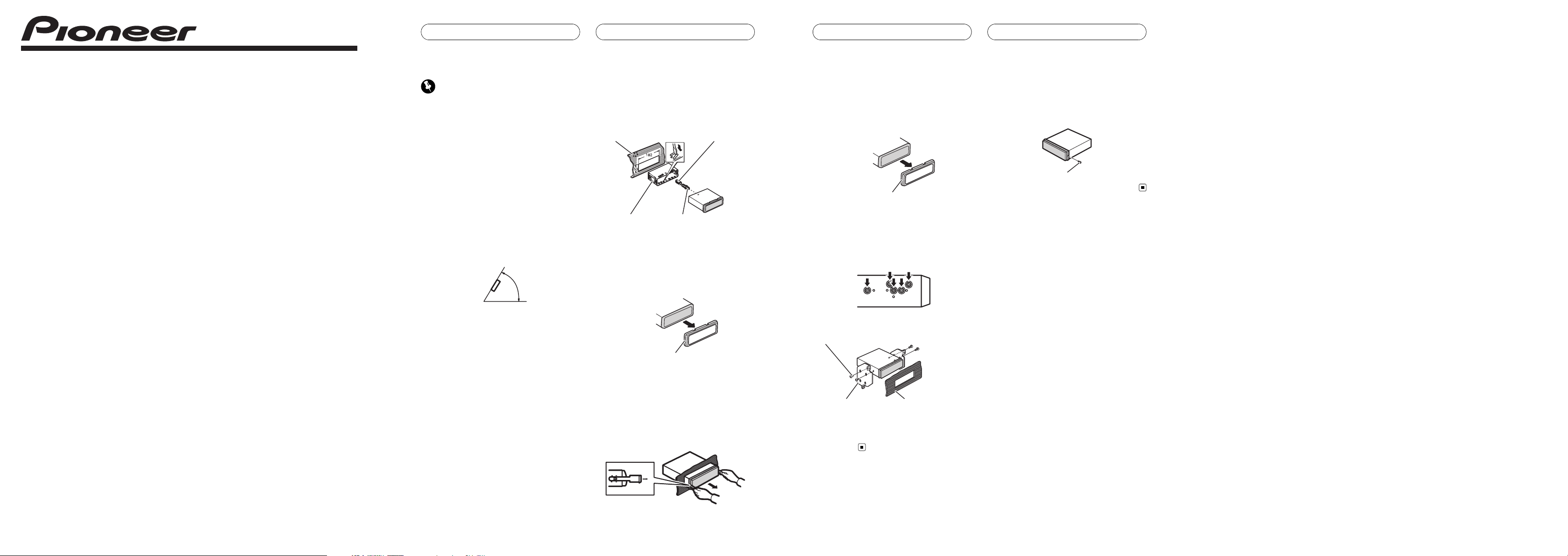
unit is installed at an angle of less than 60°.
60°
DIN front/rear mount
This unit can be properly installed either from
“Front” (conventional DIN front-mount) or
“Rear” (DIN rear-mount installation, utilizing
threaded screw holes at the sides of unit chassis). For details, refer to the following installation methods.
DIN Front-mount
Installation with the rubber bush
1 Insert the mounting sleeve into the
dashboard.
When installing in a shallow space, use a supplied mounting sleeve. If there is enough
space behind the unit, use factory supplied
mounting sleeve.
2 Secure the mounting sleeve by using a
screwdriver to bend the metal tabs (90°)
into place.
3 Install the unit.
Dashboard Rubber bush
Mounting sleeve Screw
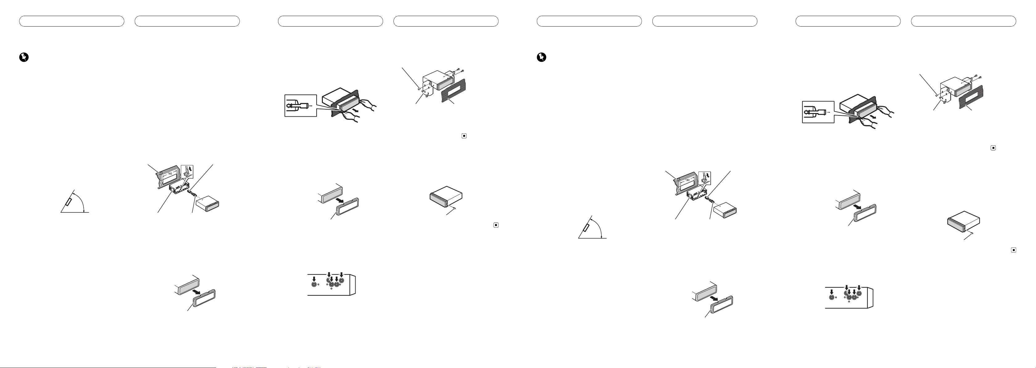
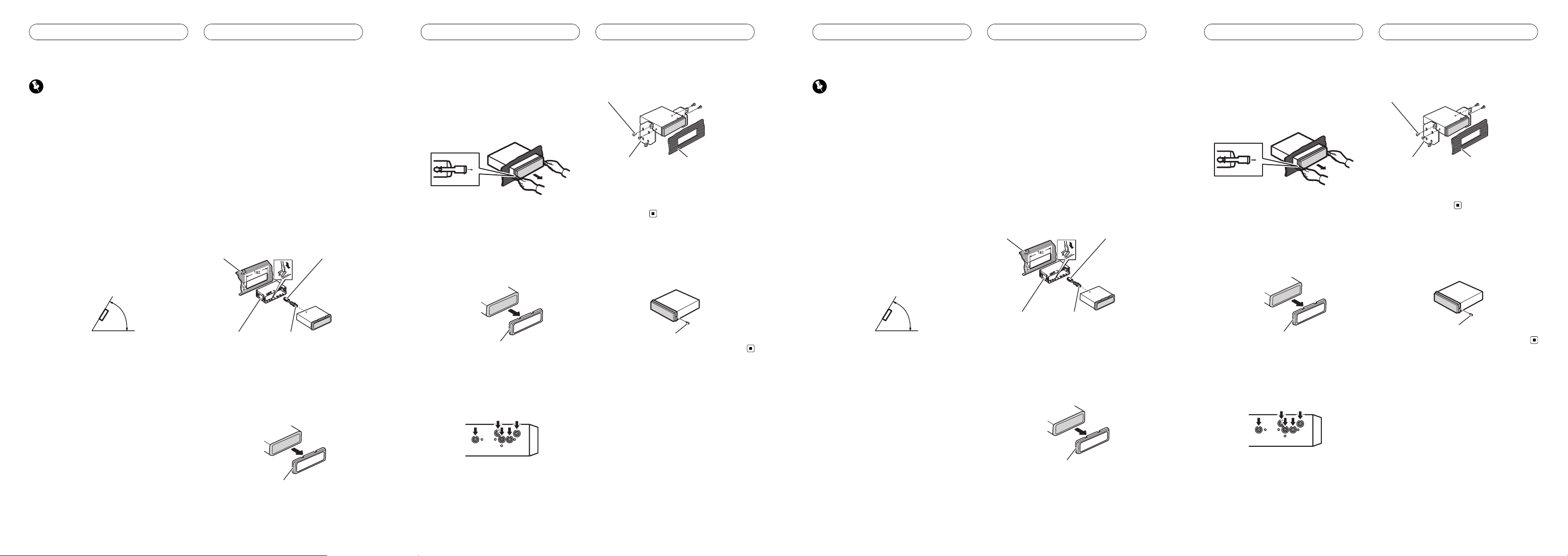
Removing the unit
1 Extend top and bottom of the trim ring
outwards to remove the trim ring. (When
reattaching the trim ring, point the side
with a groove downwards and attach it.)
Trim ring
! It becomes easy to remove the trim ring if
the front panel is released.
2 Insert the supplied extraction keys into
both sides of the unit until they click into
place.
3 Pull the unit out of the dashboard.
Installation
En
DIN Rear-mount
1 Extend top and bottom of the trim ring
outwards to remove the trim ring. (When
reattaching the trim ring, point the side
with a groove downwards and attach it.)
Trim ring
! It becomes easy to remove the trim ring if
the front panel is released.
2 Determine the appropriate position
where the holes on the bracket and the
side of the unit match.
3 Tighten two screws on each side.
Screw
Mounting bracket Dashboard or console
! Use either truss screws (5 mm × 8 mm) or
flush surface screws (5 mm × 9 mm), depending on the shape of screw holes in the
bracket.
Fastening the front panel
If you do not plan to detach the front panel,
the front panel can be fastened with supplied
screw.
Screw
Installation
En
Importante
! Compruebe todas las conexiones y sistemas
antes de la instalación final.
! No utilice piezas no autorizadas. El uso de pie-
zas no autorizadas puede causar fallos de funcionamiento.
! Consulte a su concesionario si para la instala-
ción es necesario taladrar orificios o hacer
otras modificaciones al vehículo.
! No instale esta unidad en un lugar donde:
— pueda interferir con la conducción del ve-
hículo.
— pueda lesionar a un pasajero como conse-
cuencia de un frenazo brusco.
! El láser semiconductor se dañará si se sobre-
calienta. Instale esta unidad alejada de zonas
que alcancen altas temperaturas, como cerca
de la salida del calefactor.
! Se logra un rendimiento óptimo si la unidad
se instala en un ángulo inferior a 60°.
60°
Montaje delantero/
posterior DIN
Esta unidad se puede instalar adecuadamente
ya sea de manera “delantera” (montaje delantero convencional DIN) o “posterior” (instalación de montaje posterior DIN, utilizando
agujeros roscados para tornillos en los laterales del bastidor de la unidad). Para obtener detalles, consulte los siguientes métodos de
instalación.
Montaje delantero DIN
Instalación en la arandela de goma
1 Inserte el manguito de montaje en el
salpicadero.
Si realiza la instalación en un espacio poco
profundo, utilice un manguito de montaje suministrado. Si hay suficiente espacio detrás de
la unidad, utilice un manguito de montaje suministrado de fábrica.
2 Fije el manguito de montaje utilizando
un destornillador para doblar las pestañas
metálicas (90°) y colocarlas en su lugar.
3 Instale la unidad.
Salpicadero Arandela de goma
Manguito de montaje Tornillo
Retirada de la unidad
1 Extienda hacia afuera la parte superior
e inferior del aro de guarnición para retirarlo. (Al volver a colocar el anillo de guarnición, oriente el lado que tiene una ranura
hacia abajo y colóquelo.)
Anillo de guarnición
! Resulta más fácil retirar el anillo de guarni-
ción si se suelta la carátula.
Instalación
Es
2 Inserte en ambos lados de la unidad las
llaves de extracción provistas hasta que se
escuche un ligero chasquido.
3 Extraiga la unidad del salpicadero.
Montaje trasero DIN
1 Extienda hacia afuera la parte superior
e inferior del aro de guarnición para retirarlo. (Al volver a colocar el anillo de guarnición, oriente el lado que tiene una ranura
hacia abajo y colóquelo.)
Anillo de guarnición
! Resulta más fácil retirar el anillo de guarni-
ción si se suelta la carátula.
2 Determine la posición correcta, de
modo que los orificios del soporte y del lateral de la unidad coincidan.
3 Apriete los dos tornillos en cada lado.
Tornillo
Carcasa Salpicadero o consola
! Utilice tornillos de cabeza redonda (5 mm
× 8 mm) o tornillos de cabeza embutida (5
mm × 9 mm), según la forma de los orificios roscados del soporte.
Fijación de la carátula
Si no tiene previsto sacar la carátula, ésta se
puede fijar con el tornillo suministrado.
Tornillo
Instalación
Es
Wichtig
! Überprüfen Sie vor der definitiven Installation
alle Anschlüsse und Systeme.
! Verwenden Sie ausschließlich autorisierte
Teile. Die Verwendung nicht autorisierter Teile
kann eine Funktionsstörung zur Folge haben.
! Wenden Sie sich an Ihren Fachhändler, wenn
für die Installation Löcher gebohrt oder andere Änderungen am Fahrzeug vorgenommen
werden müssen.
! Installieren Sie dieses Gerät keinesfalls an fol-
genden Orten:
— Orte, an denen das Gerät die Steuerung
des Fahrzeugs behindern könnte.
— Orte, an denen das Gerät die Insassen des
Fahrzeugs im Anschluss an eine Schnellbremsung verletzen könnte.
! Der Halbleiterlaser kann durch Überhitzung
beschädigt werden. Installieren Sie dieses
Gerät deshalb in sicherer Entfernung von Hitzequellen, wie z. B. Heizöffnungen.
! Optimale Leistung kann durch eine Installa-
tion des Geräts in einem Winkel unter 60° erzielt werden.
60°
Front-/Rückmontage nach DIN
Dieses Gerät kann sowohl über die Frontseite
(herkömmliche DIN-Frontmontage) als auch
über die Rückseite (DIN-Rückmontage unter
Rückgriff auf die Gewindelöcher an den Seiten
des Gerätegehäuses) installiert werden. Detaillierte Informationen können Sie den nachstehenden Beschreibungen dieser
Installationsmethoden entnehmen.
DIN-Frontmontage
Installation mit Gummilager
1 Führen Sie den Montagerahmen in das
Armaturenbrett ein.
Bei nur wenig Installationsraum ist der mitgelieferte Montagerahmen zu verwenden. Ist hinter dem Gerät ausreichend Freiraum
vorhanden, dann sollten Sie den werkseitig bereitgestellten Montagerahmen verwenden.
2 Befestigen Sie den Montagerahmen
mithilfe eines Schraubendrehers: Die Metallklammern sind in eine sichere Position
(90°) zu biegen.
3 Installieren Sie dieses Gerät.
Armaturenbrett Gummilager
Montagerahmen Schraube
Entfernen des Geräts
1 Ziehen Sie den Einpassungsring oben
und unten nach außen, um ihn zu entfernen. (Um den Einpassungsring wieder anzubringen, drücken Sie die Seite mit der
Nute nach unten und befestigen Sie sie.)
Einpassungsring
! Bei entriegelter Frontplatte lässt sich der
Einpassungsring problemlos entfernen.
Installation
De
2 Führen Sie die mitgelieferten Extraktionsschlüssel an beiden Geräteseiten ein,
bis sie in der richtigen Position einrasten.
3 Ziehen Sie das Gerät aus dem Armaturenbrett.
DIN-Rückmontage
1 Ziehen Sie den Einpassungsring oben
und unten nach außen, um ihn zu entfernen. (Um den Einpassungsring wieder anzubringen, drücken Sie die Seite mit der
Nute nach unten und befestigen Sie sie.)
Einpassungsring
! Bei entriegelter Frontplatte lässt sich der
Einpassungsring problemlos entfernen.
2 Bestimmen Sie die geeignete Position,
damit die Löcher an der Klammer und den
Geräteseiten ordnungsgemäß ausgerichtet
sind.
3 Ziehen Sie auf jeder Seite zwei Schrauben fest.
Schraube
Montageklammer Armaturenbrett oder Kon-
sole
! Verwenden Sie entweder Trägerschrauben
(5 mm × 8 mm) oder Oberflächenschrauben (5 mm × 9 mm), je nach der Form der
Gewindelöcher in der Klammer.
Anbringen der Frontplatte
Wenn Sie nicht vorhaben, die Frontplatte abzunehmen, kann diese auch mittels der beigefügten Schrauben permanent angebracht
werden.
Schraube
Installation
De
Important
! Vérifiez toutes les connexions et tous les systè-
mes avant l’installation finale.
! N’utilisez pas de pièces détachées non autori-
sées. L’utilisation de pièces non autorisées
peut provoquer des dysfonctionnements.
! Consultez votre revendeur si l’installation né-
cessite le perçage de trous ou d’autres modifications du véhicule.
! N’installez pas cet appareil là où :
— il peut interférer avec l’utilisation du véhi-
cule.
— il peut blesser un passager en cas d’arrêt
soudain du véhicule.
! Le laser à semi-conducteur sera endommagé
s’il devient trop chaud. Installez cet appareil à
l’écart de tous les endroits chauds, par exemple les sorties de chauffage.
! Les performances optimales sont obtenues
quand l’appareil est installé à un angle inférieur à 60°.
60°
Montage avant/arrière DIN
Cet appareil peut être installé correctement
soit à partir de “l’avant” (montage frontal DIN
conventionnel) ou de “l’arrière” (installation en
montage arrière DIN, utilisant des trous de vis
filetés sur les côtés du châssis de l’appareil).
Pour les détails, reportez-vous aux méthodes
d’installation suivantes.
Montage frontal DIN
Installation avec la douille en
caoutchouc
1 Insérez le manchon de montage dans le
tableau de bord.
Quand vous installez l’appareil dans un espace peu profond, utilisez un manchon de
montage fourni. S’il y a assez d’espace derrière l’appareil, utilisez le manchon de montage fourni en usine.
2 Fixez le manchon de montage en utilisant un tournevis pour courber les pattes
métalliques (90°) en place.
3 Installez l’appareil.
Tableau de bord Douille en caoutchouc
Manchon de montage Vis
Enlèvement de l’appareil
1 Étirez le haut et le bas de l’anneau de
garniture vers l’extérieur pour retirer la
garniture. (Quand vous remontez l’anneau
de garniture, pointez le côté avec une rainure vers le bas et fixez-le.)
Anneau de garniture
! Il est plus facile de retirer l’anneau de garni-
ture si la face avant est libérée.
Installation
Fr
2 Insérez les clés d’extraction fournies
dans les deux côtés de l’appareil jusqu’àce
qu’elles s’enclenchent en place.
3 Tirez l’appareil hors du tableau de
bord.
Montage arrière DIN
1 Étirez le haut et le bas de l’anneau de
garniture vers l’extérieur pour retirer la
garniture. (Quand vous remontez l’anneau
de garniture, pointez le côté avec une rainure vers le bas et fixez-le.)
Anneau de garniture
! Il est plus facile de retirer l’anneau de garni-
ture si la face avant est libérée.
2 Déterminez la position appropriée où
les trous sur le support et sur le côté de
l’appareil se correspondent.
3 Serrez deux vis de chaque côté.
Vis
Support de montage Tableau de bord ou
console
! Utilisez des vis à tête bombée (5 mm × 8
mm) ou des vis en affleurement (5 mm × 9
mm), selon la forme des trous de vis dans
le support.
Fixation de la face avant
Si vous ne souhaitez pas détacher la face
avant, elle peut être fixée avec les vis fournies.
Vis
Installation
Fr
Importante
! Controllare tutti i collegamenti e i sistemi
prima dell’installazione finale.
! Non utilizzare componenti non approvati, poi-
ché potrebbero provocare malfunzionamenti.
! Consultare il rivenditore se l’installazione ri-
chiede la trapanatura di fori o altre modifiche
del veicolo.
! Non installare questa unità se:
— potrebbe interferire con il funzionamento
del veicolo.
— potrebbe procurare lesioni al passeggero
in caso di arresto improvviso del veicolo.
! Se si surriscalda il laser a semiconduttore po-
trebbe subire danni. Non installare questa
unità in luoghi soggetti a surriscaldamento,
come in prossimità delle bocchette dell’impianto di riscaldamento.
! Le prestazioni ottimali si ottengono quando
l’unità viene installata con un’angolazione inferiore a 60°.
60°
Montaggio DIN an teriore/
posteriore
Questa unità può essere installata correttamente sia dalla posizione “Anteriore” (montaggio DIN anteriore convenzionale) sia dalla
posizione “Posteriore” (montaggio DIN posteriore, per mezzo di fori per le viti ai lati del telaio) Per dettagli, vedere i seguenti metodi di
installazione.
Montaggio DIN anteriore
Installazione con boccola in gomma
1 Inserire la fascetta di montaggio nel
cruscotto.
Se l’unità viene installata in uno spazio poco
profondo, utilizzare una fascetta di montaggio
fornita. Se dietro l’unità vi è spazio sufficiente,
utilizzare la fascetta di montaggio fornita.
2 Assicurare la fascetta di montaggio utilizzando un cacciavite per piegare le linguette metalliche (90°) in posizione.
3 Installazione dell’unità.
Cruscotto Boccola in gomma
Fascetta di montaggio Vite
Rimozione dell’unità
1 Estendere verso l’esterno la parte superiore e inferiore della guarnizione per rimuovere la guarnizione. (Quando si
riapplica la guarnizione, spingere il lato
verso il basso con una guida e applicarla.)
Guarnizione
! Risulterà facile rimuovere la guarnizione
col frontalino rimosso.
Installazione
It
2 Inserire le chiavi di estrazione fornite
su entrambi i lati dell’unità fino a che non
scattano in posizione.
3 Estrarre l’ unità dal cruscotto.
Montaggio DIN posteriore
1 Estendere verso l’esterno la parte superiore e inferiore della guarnizione per rimuovere la guarnizione. (Quando si
riapplica la guarnizione, spingere il lato
verso il basso con una guida e applicarla.)
Guarnizione
! Risulterà facile rimuovere la guarnizione
col frontalino rimosso.
2 Determinare la posizione appropriata,
in modo che i fori sulla staffa e sul lato dell’unità corrispondano.
3 Serrare due viti su ciascun lato.
Vite
Staffa di montaggio Cruscotto o console
! Utilizzare viti a testa tonda (da 5 mm × 8
mm) o viti a testa piana svasata (da 5 mm
× 9 mm), a seconda della forma dei fori per
le viti sulla staffa.
Rimuovere il frontalino
Se non si intende distaccare il frontalino, questo può essere fissato con le viti fornite.
Vite
Installazione
It
 Loading...