

Page 1
PIONEER CORPORATION 4-1, Meguro 1-chome, Meguro-ku, Tokyo 153-8654, Japan
PIONEER ELECTRONICS (USA) INC. P.O. Box 1760, Long Beach, CA 90801-1760, U.S.A.
PIONEER EUROPE NV Haven 1087, Keetberglaan 1, 9120 Melsele, Belgium
PIONEER ELECTRONICS ASIACENTRE PTE. LTD. 253 Alexandra Road, #04-01, Singapore 159936
PIONEER CORPORATION 2008
AVIC-F700BT/XS/UC
FLASH MEMORY MULTIMEDIA AV NAVIGATION RECEIVER
ORDER NO.
CRT4157
AVIC-F700BT
AVIC-F7010BT
NAVIGATION AV SYSTEM
AVIC-F700BT
This service manual should be used together with the following manual(s):
Model No. Order No. Mech.Module Remarks
CX-3195 CRT3815 S10.5COMP2 CD Mech. Module : Circuit Descriptions, Mech. Descriptions, Disassembly
/XS/UC
/XS/EW5
/XS/UC
For details, refer to "Important Check Points for Good Servicing".
K-ZZZ.-001 MAY 2008 Printed in Japan
Page 2

1234
1234
C
D
F
A
B
E
SAFETY INFORMATION
CAUTION:
USE OF CONTROLS OR ADJUSTMENTS OR PERFORMANCE OF PROCEDURES OTHER THAN THOSE
SPECIFIED HEREIN MAY RESULT IN HAZARDOUS RADIATION EXPOSURE.
- Safety Precautions for those who Service this Unit.
When checking or adjusting the emitting power of the laser diode exercise caution in order to get safe, reliable
results.
Caution:
1. During repair or tests, minimum distance of 13 cm from the focus lens must be kept.
2. During repair or tests, do not view laser beam for 10 seconds or longer.
CAUTION
WARNING
Where in a manufacturer’s service documentation, for example in circuit diagrams or lists
of components, a symbol is used to indicate that a specific component shall be replaced only
by the component specified in that documentation for safety reasons, the following symbol shall
be used:
The backlighting lamp of LCD in this equipment contains mercury. Disposal of this material may be
regulated due to environmental considerations according to Local, State or Federal Laws. For disposal
or recycling information, please contact your local authorities or the Electronics Industries
Alliance: www.eiae.org
This product contains mercury. Disposal of this material may be regulated due to environmental considerations.
For disposal or recycling information, please contact your local authorities or the Electronics Industries
Alliance: www.eiae.org.
This product contains certain electrical parts contain chemicals which are known to the State of
California to cause cancer, birth defects or other reproductive harm.
Health & Safety Code Section 25249.6 - Proposition 65
This service manual is intended for qualified service technicians; it is not meant for the casual do-it-yourselfer.
Qualified technicians have the necessary test equipment and tools, and have been trained to properly and safely repair
complex products such as those covered by this manual.
Improperly performed repairs can adversely affect the safety and reliability of the product and may void the warranty.
If you are not qualified to perform the repair of this product properly and safely, you should not risk trying to do so
and refer the repair to a qualified service technician.
2
AVIC-F700BT/XS/UC
Page 3
5678
56
7
8
C
D
F
A
B
E
WARNING!
The AEL (accessible emission level )of the laser power output is less than CLASS 1
but the laser component is capable of emitting radiation exceeding the limit for
CLASS 1.
A specially instructed person should do servicing operation of the apparatus.
Laser diode characteristics
Wave length : 785 nm to 814 nm
Maximum output : 1 190 W(Emitting period : unlimited)
Additional Laser Caution
Transistors Q101 in PCB drive the laser diodes.
When Q101 is shorted between their terminals, the laser diodes will radiate beam.
If the top cover is removed with no disc loaded while such short-circuit is continued,
the naked eyes may be exposed to the laser beam.
AVIC-F700BT/XS/UC
3
Page 4
1234
1234
C
D
F
A
B
E
[Important Check Points for Good Servicing]
In this manual, procedures that must be performed during repairs are marked with the below symbol.
Please be sure to confirm and follow these procedures.
1. Product safety
Please conform to product regulations (such as safety and radiation regulations), and maintain a safe servicing environment by
following the safety instructions described in this manual.
1 Use specified parts for repair.
Use genuine parts. Be sure to use important parts for safety.
2 Do not perform modifications without proper instructions.
Please follow the specified safety methods when modification(addition/change of parts) is required due to interferences such as
radio/TV interference and foreign noise.
3 Make sure the soldering of repaired locations is properly performed.
When you solder while repairing, please be sure that there are no cold solder and other debris.
Soldering should be finished with the proper quantity. (Refer to the example)
4 Make sure the screws are tightly fastened.
Please be sure that all screws are fastened, and that there are no loose screws.
5 Make sure each connectors are correctly inserted.
Please be sure that all connectors are inserted, and that there are no imperfect insertion.
6 Make sure the wiring cables are set to their original state.
Please replace the wiring and cables to the original state after repairs.
In addition, be sure that there are no pinched wires, etc.
7 Make sure screws and soldering scraps do not remain inside the product.
Please check that neither solder debris nor screws remain inside the product.
8 There should be no semi-broken wires, scratches, melting, etc. on the coating of the power cord.
Damaged power cords may lead to fire accidents, so please be sure that there are no damages.
If you find a damaged power cord, please exchange it with a suitable one.
9 There should be no spark traces or similar marks on the power plug.
When spark traces or similar marks are found on the power supply plug, please check the connection and advise on secure
connections and suitable usage. Please exchange the power cord if necessary.
a Safe environment should be secured during servicing.
When you perform repairs, please pay attention to static electricity, furniture, household articles, etc. in order to prevent injuries.
Please pay attention to your surroundings and repair safely.
2. Adjustments
To keep the original performance of the products, optimum adjustments and confirmation of characteristics within specification.
Adjustments should be performed in accordance with the procedures/instructions described in this manual.
4. Cleaning
For parts that require cleaning, such as optical pickups, tape deck heads, lenses and mirrors used in projection monitors, proper
cleaning should be performed to restore their performances.
3. Lubricants, Glues, and Replacement parts
Use grease and adhesives that are equal to the specified substance.
Make sure the proper amount is applied.
5. Shipping mode and Shipping screws
To protect products from damages or failures during transit, the shipping mode should be set or the shipping screws should be
installed before shipment. Please be sure to follow this method especially if it is specified in this manual.
4
AVIC-F700BT/XS/UC
Page 5

5678
56
7
8
C
D
F
A
B
E
CONTENTS
SAFETY INFORMATION .....................................................................................................................................2
1. SERVICE PRECAUTIONS................................................................................................................................6
1.1 SERVICE PRECAUTIONS.........................................................................................................................6
1.2 NOTES ON SOLDERING...........................................................................................................................7
2. SPECIFICATIONS.............................................................................................................................................8
2.1 SPECIFICATIONS......................................................................................................................................8
2.2 DISC/CONTENT FORMAT.......................................................................................................................11
2.3 PANEL FACILITIES ..................................................................................................................................12
2.4 CONNECTION DIAGRAM........................................................................................................................15
3. BASIC ITEMS FOR SERVICE........................................................................................................................17
3.1 CHECK POINTS AFTER SERVICING.....................................................................................................17
3.2 PCB LOCATIONS.....................................................................................................................................18
3.3 JIGS LIST.................................................................................................................................................19
3.4 CLEANING ...............................................................................................................................................20
4. BLOCK DIAGRAM ..........................................................................................................................................22
4.1 OVERALL CONNECTION DIAGRAM......................................................................................................22
4.2 BLOCK DIAGRAM....................................................................................................................................24
4.3 POWER SUPPLY SYSTEM FIGURE.......................................................................................................32
5. DIAGNOSIS ....................................................................................................................................................36
5.1 OPERATIONAL FLOWCHART.................................................................................................................36
5.2 ERROR CODE LIST.................................................................................................................................38
5.3 CONNECTOR FUNCTION DESCRIPTION .............................................................................................39
5.4 TROUBLESHOOTING..............................................................................................................................40
6. SERVICE MODE.............................................................................................................................................44
6.1 TEST MODE.............................................................................................................................................44
6.2 CD TEST MODE.......................................................................................................................................56
6.3 uBOOT MENU..........................................................................................................................................59
6.4 USING THE TEST DISC ..........................................................................................................................60
7. DISASSEMBLY...............................................................................................................................................66
8. EACH SETTING AND ADJUSTMENT............................................................................................................75
8.1 CHECKING THE GRATING AFTER CHANGING THE PICKUP UNIT....................................................75
8.2 AV UNIT ADJUSTMENT...........................................................................................................................77
8.3 FLICKER ADJUSTMENT .........................................................................................................................79
9. EXPLODED VIEWS AND PARTS LIST..........................................................................................................80
9.1 PACKING..................................................................................................................................................80
9.2 EXTERIOR(1)...........................................................................................................................................84
9.3 EXTERIOR(2)...........................................................................................................................................86
9.4 EXTERIOR(3)...........................................................................................................................................88
9.5 CD MECHANISM MODULE.....................................................................................................................90
10. SCHEMATIC DIAGRAM................................................................................................................................92
10.1 AV UNIT(PS/IF SECTION)(GUIDE PAGE) .............................................................................................92
10.2 AV UNIT(A/V SECTION)(GUIDE PAGE) ................................................................................................98
10.3 AV UNIT(TUNER SECTION)................................................................................................................104
10.4 AV UNIT(SYSTEM uCOM SECTION)(GUIDE PAGE)..........................................................................106
10.5 AV UNIT(RGB LED DRIVER SECTION)..............................................................................................112
10.6 AV UNIT(IF SECTION)(GUIDE PAGE).................................................................................................114
10.7 KEYBOARD UNIT ................................................................................................................................120
10.8 CD MECHANISM MODULE(GUIDE PAGE).........................................................................................122
10.9 WAVEFORMS.......................................................................................................................................128
11. PCB CONNECTION DIAGRAM ..................................................................................................................130
11.1 AV UNIT................................................................................................................................................130
11.2 KEYBOARD UNIT.................................................................................................................................134
11.3 CD CORE UNIT(S10.5COMP2) ....................................................................................................
.......136
12. ELECTRICAL PARTS LIST.........................................................................................................................138
AVIC-F700BT/XS/UC
5
Page 6
1234
1234
C
D
F
A
B
E
1. SERVICE PRECAUTIONS
1. You should conform to the regulations governing the product (safety, radio and noise, and other regulations),
and should keep the safety during servicing by following the safety instructions described in this manual.
2. Be careful in handling ICs. Some ICs such as MOS type are so fragile that they can be damaged by electrostatic
induction.
3. To protect the pickup unit from electrostatic discharge during servicing, take an appropriate treatment
(shorting-solder) by referring to "the DISASSEMBLY".
4. After replacing the pickup unit, be sure to check the grating.
EJECT LOCK MODE for CD mechanism
In order to change the EJECT LOCK/UNLOCK status of the mechanism, please perform following procedure.
< Procedure >
Top Menu -> AV Source -> Source OFF
Short push area "A" -> Short push area "B" -> Long push area "C" on above screen.
(In order to change the status, follow the same operation.)
The current status can be confirmed by "OFF" character color.
A
B
C
Eject Lock: ON
Eject Lock: OFF
The Bluetooth word mark and logos are owned by the Bluetooth SIG, Inc.
and any use of such marks by Pioneer Corporation is under license.
Other trademarks and trade names are those of their respective owners.
1.1 SERVICE PRECAUTIONS
6
AVIC-F700BT/XS/UC
Page 7

5678
56
7
8
C
D
F
A
B
E
For environmental protection, lead-free solder is used on the printed circuit boards mounted in this unit.
Be sure to use lead-free solder and a soldering iron that can meet specifications for use with lead-free solders for repairs
accompanied by reworking of soldering.
Compared with conventional eutectic solders, lead-free solders have higher melting points, by approximately 40 C.
Therefore, for lead-free soldering, the tip temperature of a soldering iron must be set to around 373 C in general, although
the temperature depends on the heat capacity of the PC board on which reworking is required and the weight of the tip of
the soldering iron.
Compared with eutectic solders, lead-free solders have higher bond strengths but slower wetting times and higher melting
temperatures (hard to melt/easy to harden).
The following lead-free solders are available as service parts:
Parts numbers of lead-free solder:
GYP1006 1.0 in dia.
GYP1007 0.6 in dia.
GYP1008 0.3 in dia.
1.2 NOTES ON SOLDERING
AVIC-F700BT/XS/UC
7
Page 8
1234
1234
C
D
F
A
B
E
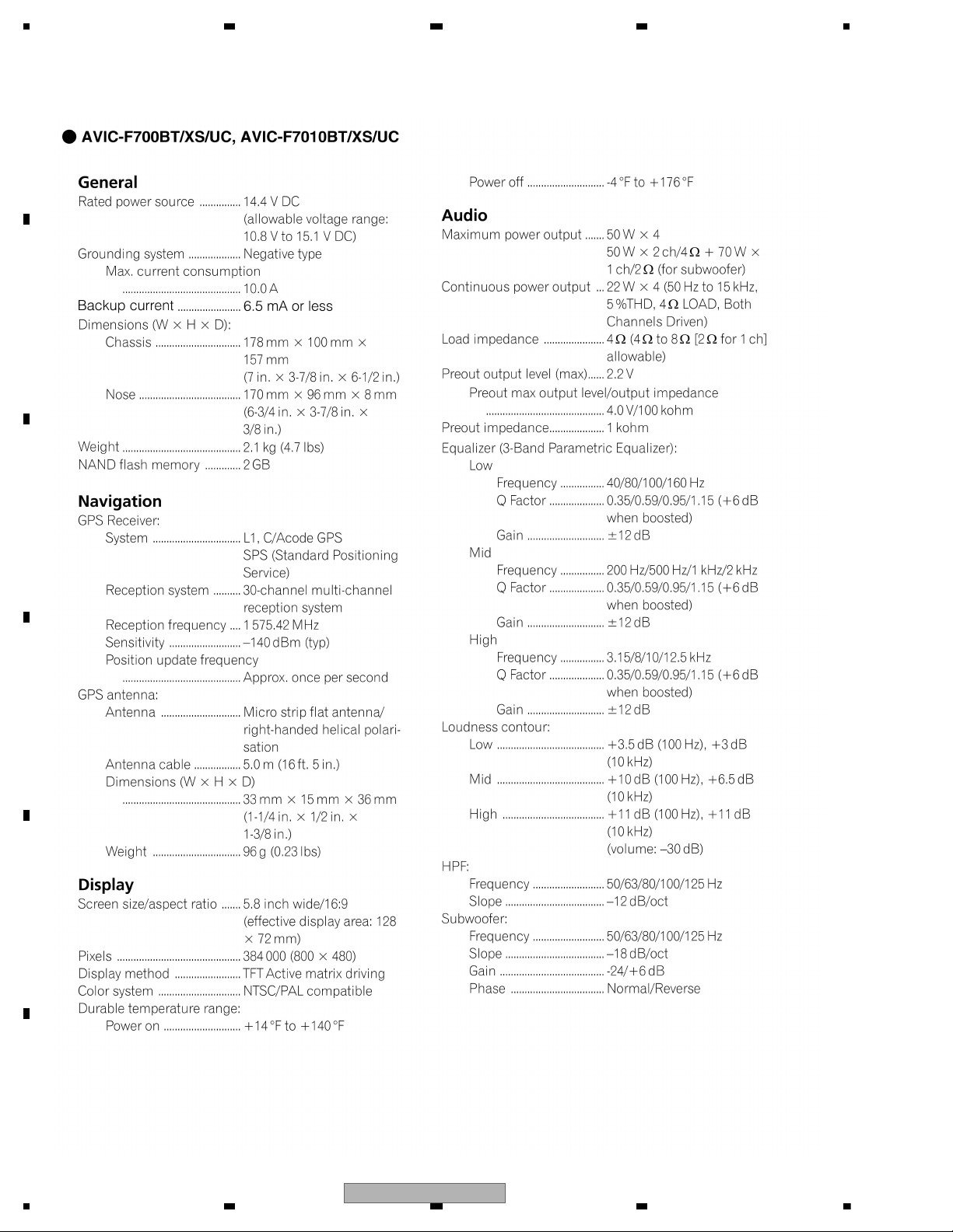
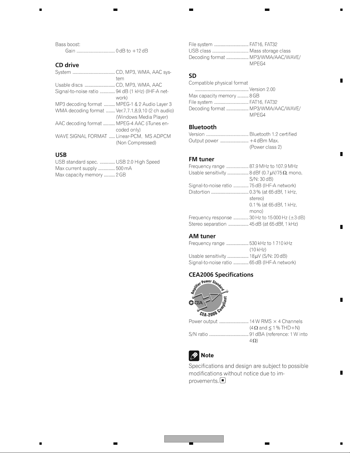
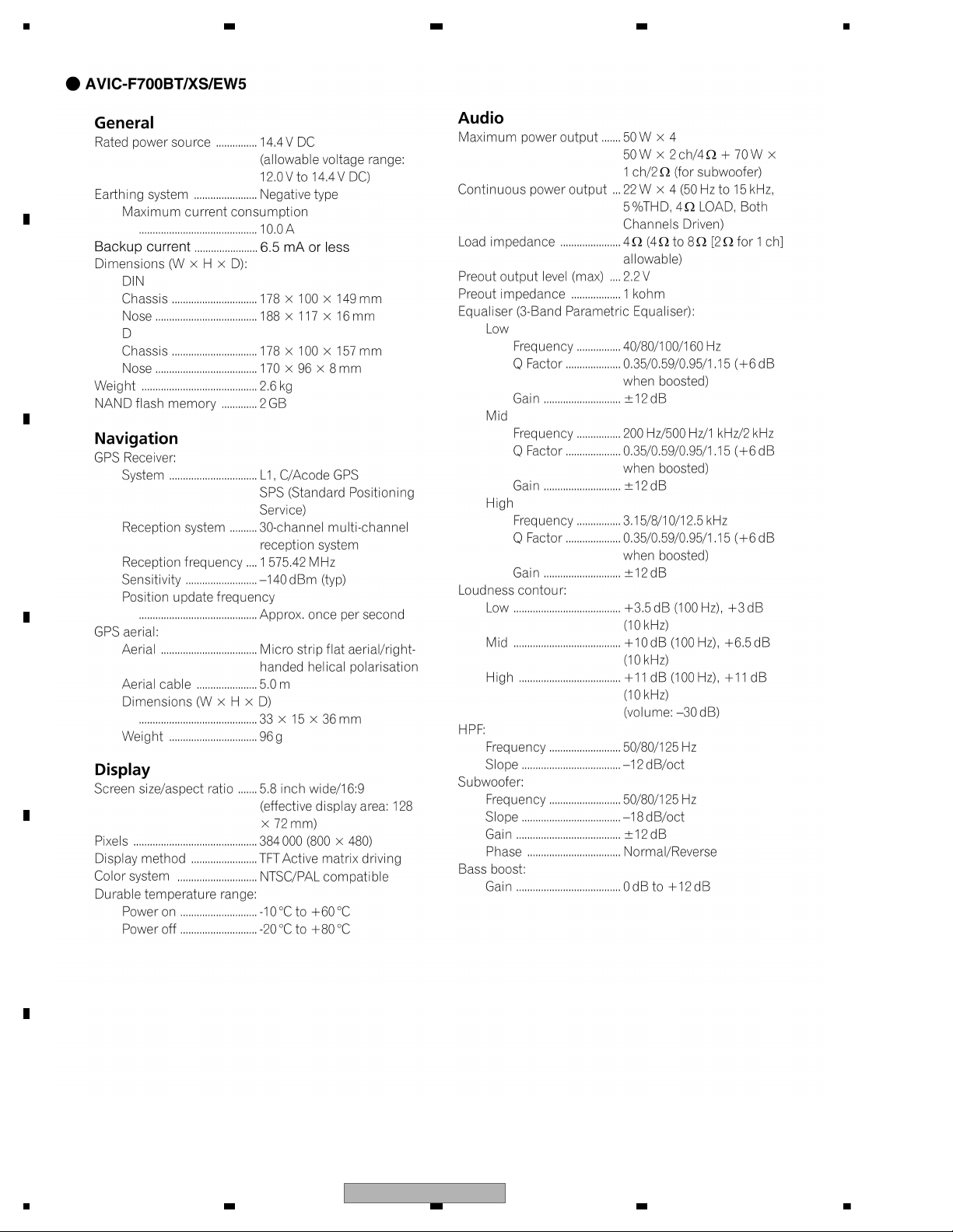
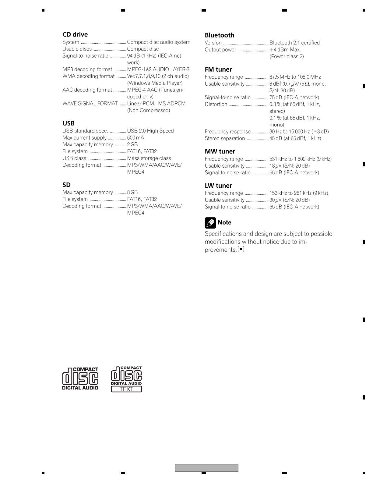
2. SPECIFICATIONS
2.1 SPECIFICATIONS
8
AVIC-F700BT/XS/UC
Page 9
5678
56
7
8
C
D
F
A
B
E
AVIC-F700BT/XS/UC
9
Page 10
1234
1234
C
D
F
A
B
E
10
AVIC-F700BT/XS/UC
Page 11
5678
56
7
8
C
D
F
A
B
E
2.2 DISC/CONTENT FORMAT
AVIC-F700BT/XS/UC
11
Page 12
1234
1234
C
D
F
A
B
E
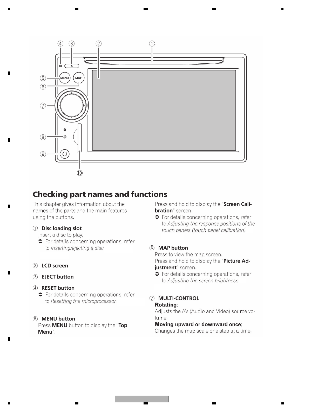
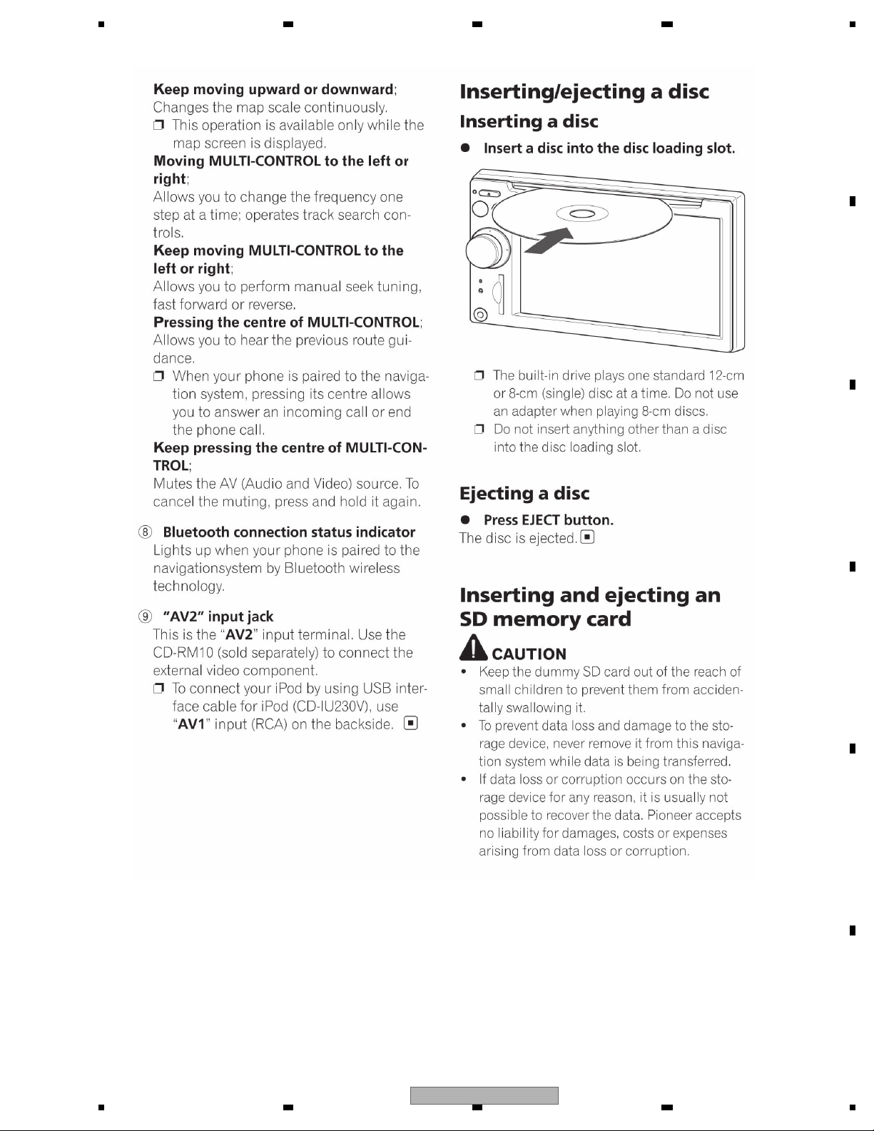
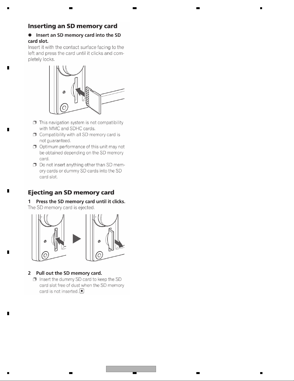
2.3 PANEL FACILITIES
.
.
.
.
12
AVIC-F700BT/XS/UC
Page 13
5678
56
7
8
C
D
F
A
B
E
AVIC-F700BT/XS/UC
13
Page 14
1234
1234
C
D
F
A
B
E
14
AVIC-F700BT/XS/UC
Page 15
5678
56
7
8
C
D
F
A
B
E
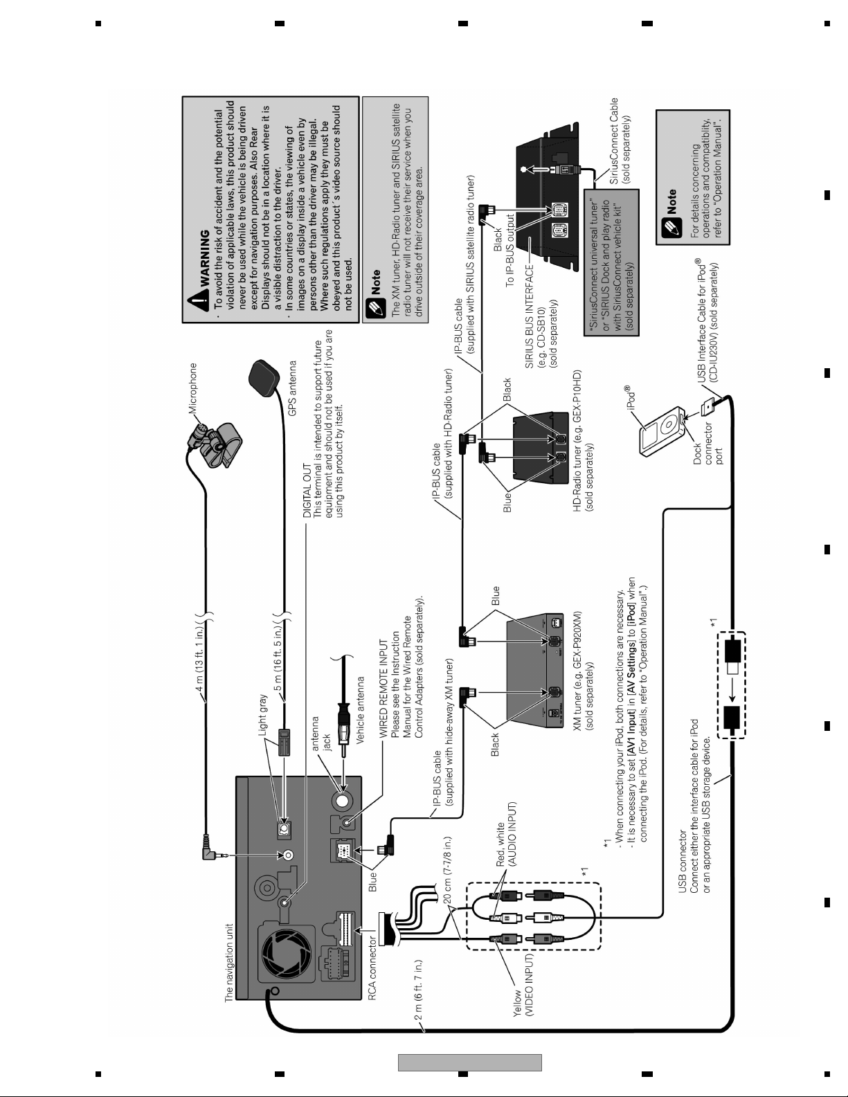
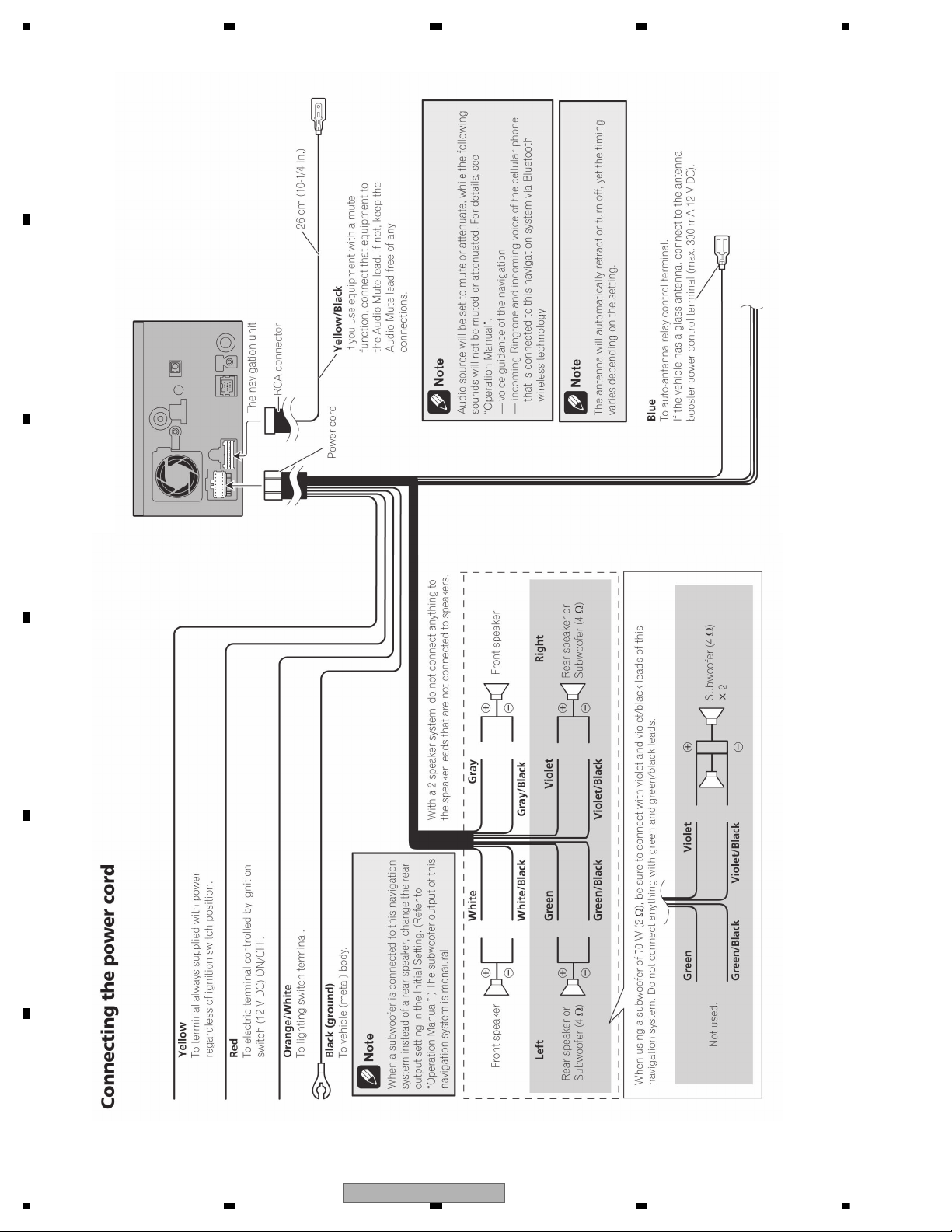
2.4 CONNECTION DIAGRAM
AVIC-F700BT/XS/UC
15
Page 16
1234
1234
C
D
F
A
B
E
16
AVIC-F700BT/XS/UC
Page 17
5678
56
7
8
C
D
F
A
B
E
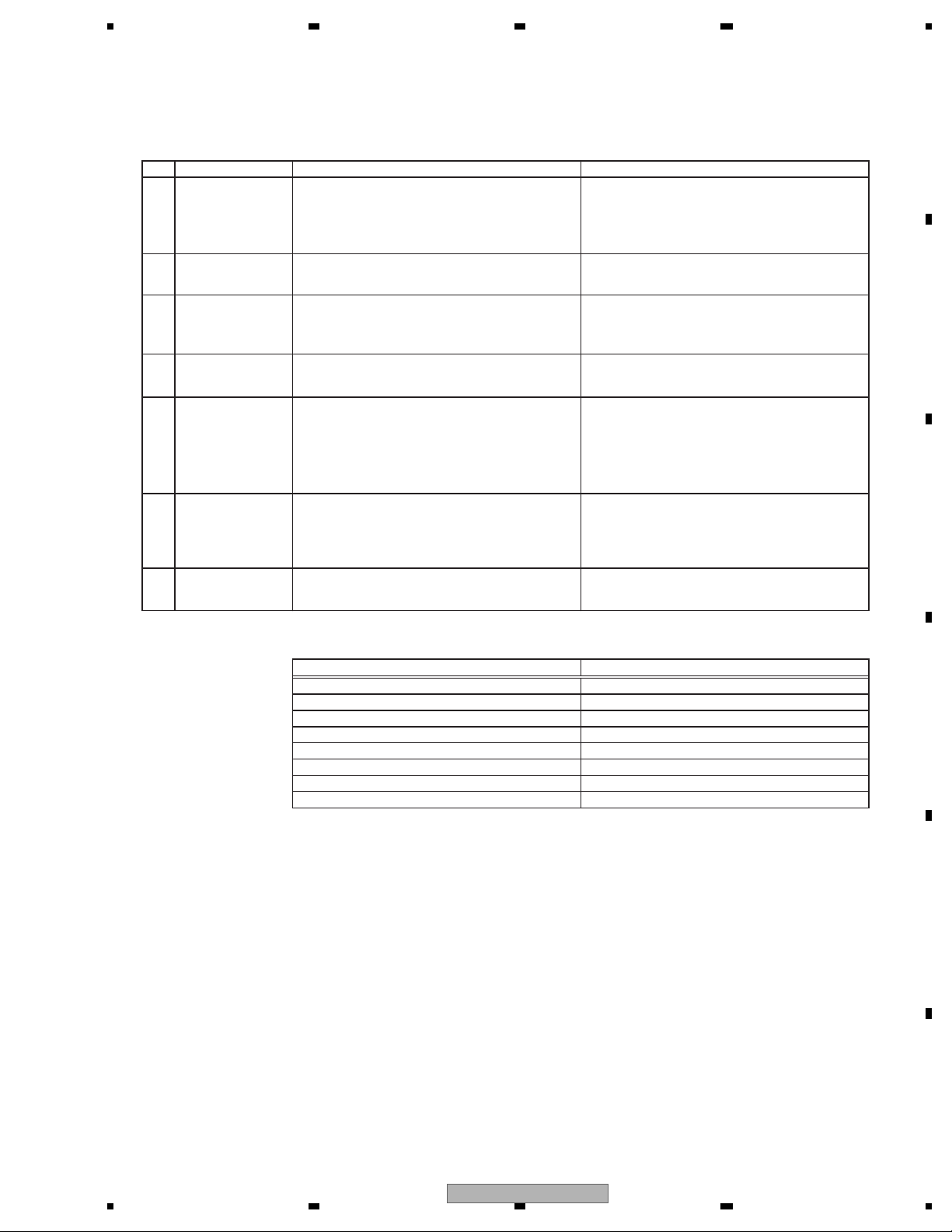
To keep the product quality after servicing, please confirm following check points.
demrifnocebotmetIserudecorP.oN
1 Confirm whether the customer complain has
been solved.
If the customer complain occurs with the
specific media, use it for the operation check.
The customer complain must not be
reappeared.
Display, video, audio and operations must be
normal.
2 CD Play back a CD.
(Track search)
Display, audio and operations must be
normal.
3 FM/AM tuner Check FM/AM tuner action.
(Seek, Preset)
Switch band to check both FM and AM.
Display, audio and operations must be
normal.
4 GPS positioning Connect GPS antenna to the product, and
check whether the current location is correct.
Current location must be correct.
Display and operations must be normal.
5 Map display
Touch-panel
operation
Remote-control
operation
Check functions of map scale change and
map scroll.
Display and operations must be normal.
6 data added during the operating
check.
Check whether no media (CD etc.) is inside
the product.
Make sure to delete data added during the
operating check.
The media used for the operating check must
be ejected.
retfaecnaraeppastinotridrosehctarcsoNkceh
cecnaraeppA7
receiving it for service.
See the table below for the items to be checked regarding video and audio:
Item to be checked regarding video
Item to be checked regarding audio
noitrotsiDesion-kcolB
esioNesionlatnoziroH
wolootemuloVesiontoD
Disturbed image (video jumpiness) Volume too high
gnitautculfemuloVkradooT
detpurretnidnuoSthgirbooT
Mottled color
3. BASIC ITEMS FOR SERVICE
3.1 CHECK POINTS AFTER SERVICING
AVIC-F700BT/XS/UC
17
Page 18
1234
1234
C
D
F
A
B
E
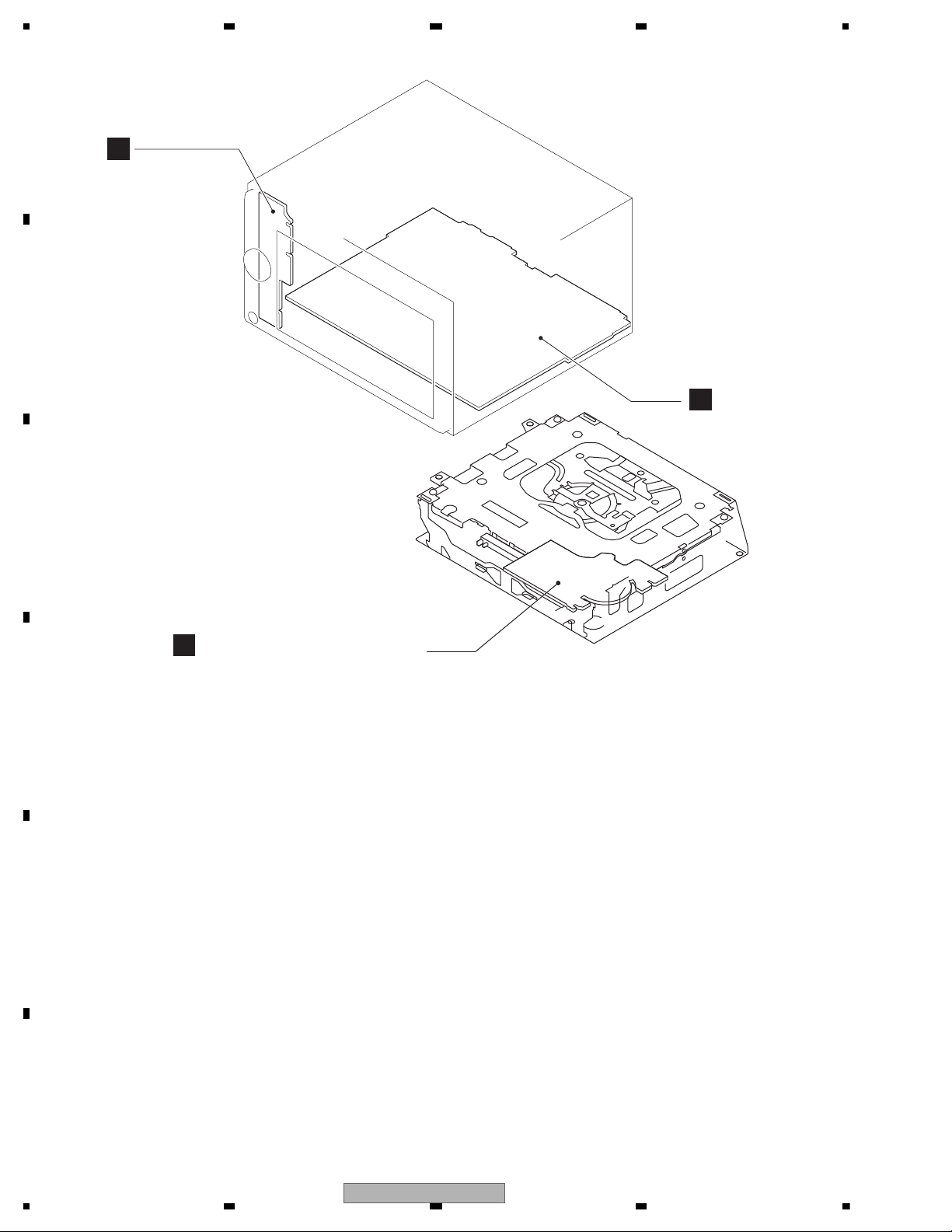
3.2 PCB LOCATIONS
C
CD Core Unit(S10.5COMP2)
B
AV Unit
A
Keyboard Unit
Unit Number : CWN3170(UC)
Unit Number : CWN3168(EW5)
Unit Name : AV Unit
Unit Number :
Unit Name : Keyboard Unit
Unit Number : CWX3514
Unit Name : CD Core Unit(S10.5COMP2)
18
AVIC-F700BT/XS/UC
Page 19
5678
56
7
8
C
D
F
A
B
E
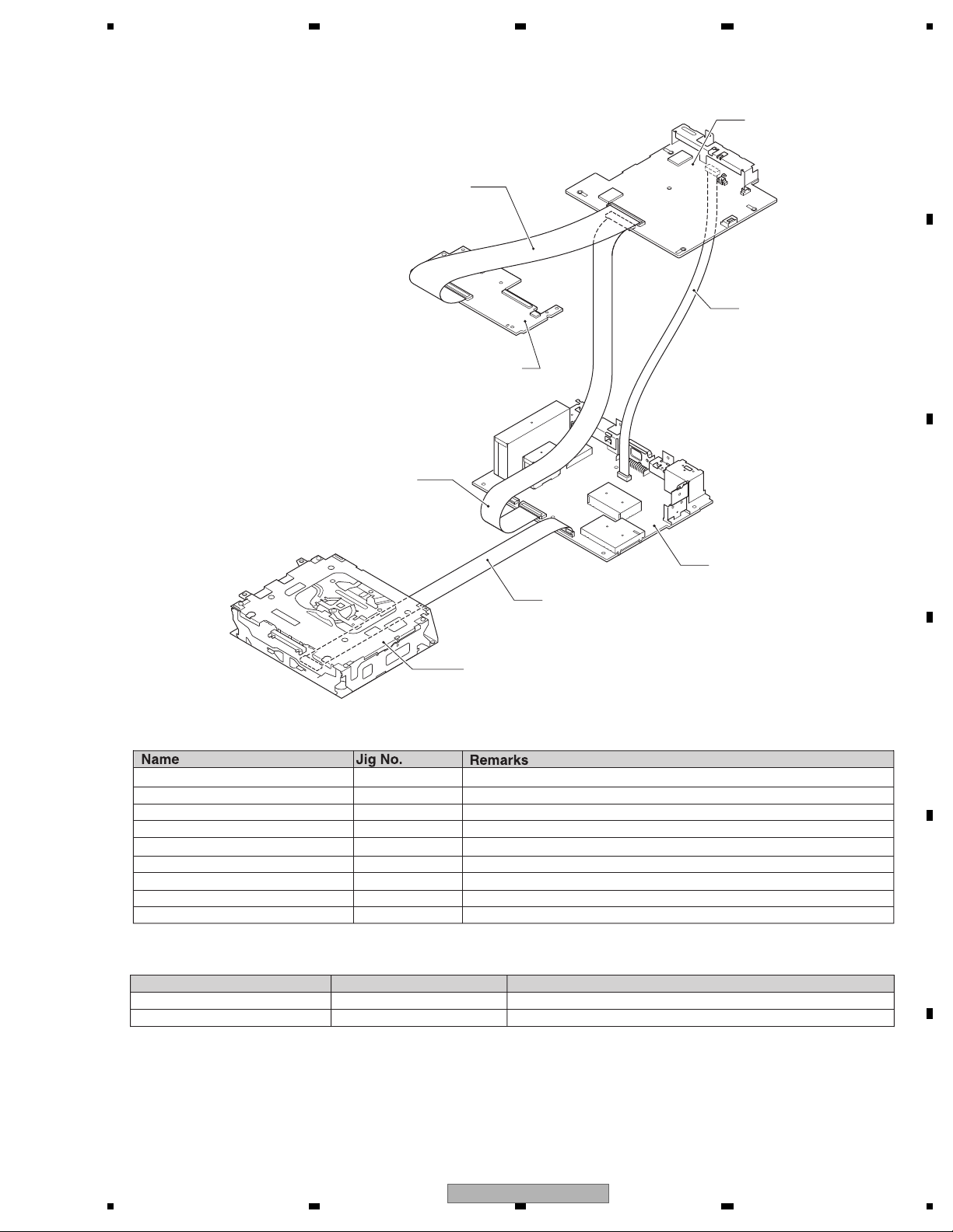
15P FFC GGD1123 Navi Unit <---> SD Unit
74P FFC GGD1560 Navi Unit <---> Panel Unit
50P FFC GGD1250 Navi Unit <---> AV Unit
20P Extension Cable GGD1327 Navi Unit <---> AV Unit
TORX screwdriver GGK1068 T8 (For top cover)
15P BBR GGD1561 AV Unit <---> CD Mechanism Module
Test Disc TCD-782 Checking the grating
L.P.F. Checking the grating (Two pieces)
Service Data Disc GGV1322 for Test Mode, Test Disc
- Grease List
Name
Grease
Grease
Grease No.
GEM1024
GEM1045
Remarks
CD Mechanism Module
CD Mechanism Module
GGD1327
Navi Unit
GGD1250
GGD1560
CD Mechanism Module
Panel Unit
GGD1561
AV Unit
- Jigs List
3.3 JIGS LIST
AVIC-F700BT/XS/UC
19
Page 20

1234
1234
C
D
F
A
B
E
3.4 CLEANING
Before shipping out the product, be sure to clean the following portions by using the prescribed cleaning tools:
Portions to be cleaned Cleaning tools
CD pickup lenses Cleaning liquid : GEM1004
Cleaning paper : GED-008
Portions to be cleaned Cleaning tools
Fans Cleaning paper : GED-008
20
AVIC-F700BT/XS/UC
Page 21

5678
56
7
8
C
D
F
A
B
E
AVIC-F700BT/XS/UC
21
Page 22
1234
1234
C
D
F
A
B
E
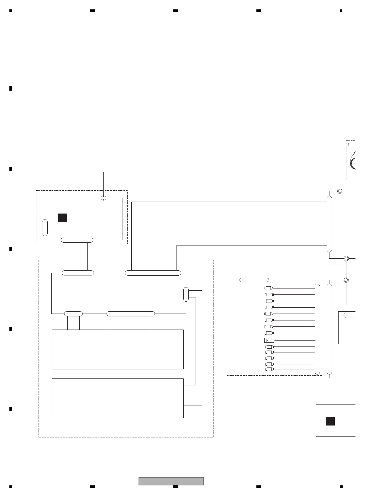
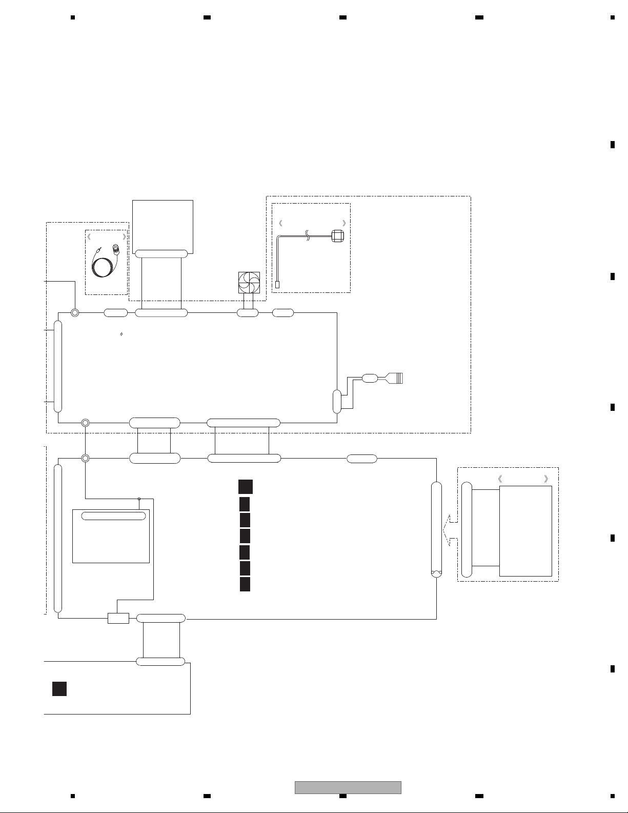
4. BLOCK DIAGRAM
}
}
}
}
60
LCJ3
1
REAR CAMERA INPUT
REAR MONITOR OUTPUT
MIC
CP
MUTE
REAR OUTPUT
FRONT OUTPUT
1
24
AUDIO INPUT
VIDEO INPUT1
SUBWOOFER OUTPUT
SYSTEM REMOTE CONTROL
CORD ASSY
CN801
1
1
74
LCJ1
42
FM/AM
1
24
CN803
OTJ2
11
OTJ1
1
10
1
LCJ6
LCJ1
ANT1
CN1
LCD MODULE
PANEL UNIT
TOUCH PANEL
CWX3611
CWX3651
CWX1136
CD ME
1
4
LCD MODULE ASSY
VIDEO INPUT2
BTJ2
CN802
FM/AM ANT
CN1016
(AV MINI
JACK IN)
TMJ1
22
22
4
74
CXC8914
C
B
KEYBOARD UNIT
:CDP1143
AVIC-F700BT/XS/EW5 :CDP1092
AVIC-F700BT/XS/UC
AVIC-F7010BT/XS/UC
4.1 OVERALL CONNECTION DIAGRAM
22
AVIC-F700BT/XS/UC
Page 23
5678
56
7
8
C
D
F
A
B
E
FAN
GND
10A
POWER SUPPLY
TERMINALS
ACC
PKB
ILM
RR-
FL-
RR+
FL+
RL-
FR-
FR+
RL+
CN1005
150
OTJ1
MIC ASSY
GPS ANTENNA ASSY
CXC8574
CPM1064
1
16
AANT
REV
PULSE
5
1
CORD ASSY
SPJ2
21
1
74
LCJ1
SPJ1
1
OTJ5
1
MIC
BLACK
2.5
1
142
FM/AM TUNER UNIT
GPJ1
31
CN1001
20
11
CN1000
50
1
24
1
ANT1401
CN1441
SD UNIT
CWX3652
CXM1320
115
CD MECHANISM MODULE
115
USB
OTJ6
OTJ11
BTJ2
FM/AM ANTENNA IN
CDE8561
BUP
CN701
CN701
CN1016
OTJ2
TMJ1
1
16
1
CN1021
IP BUS
11
20
NAVI UNIT
6
15
15
TUNER SECTION
SYSTEM uCOM SECTION
RGB LED DRIVER SECTION
IF SECTION
A/V SECTION
PS/IF SECTION
A
AV UNIT
1/6
A
2/6
A
3/6
A
4/6
A
5/6
A
6/6
A
C
AVIC-F700BT/XS/UC
23
Page 24
1234
1234
C
D
F
A
B
E
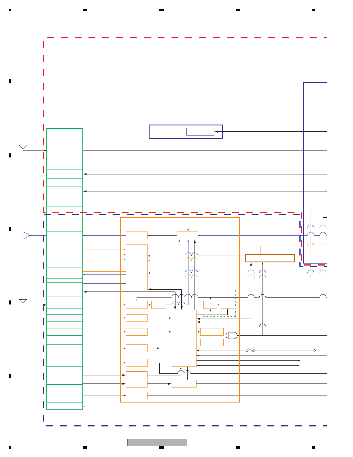
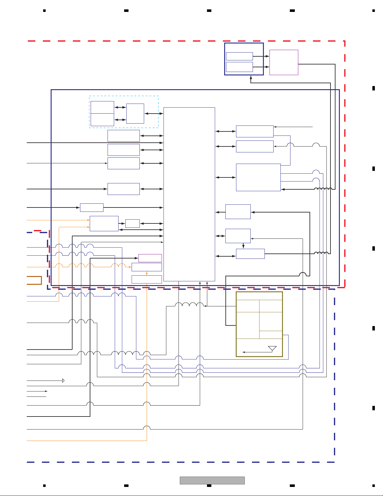
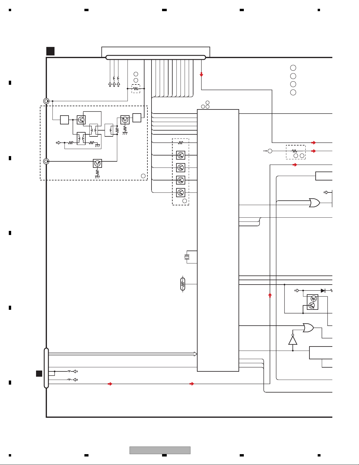
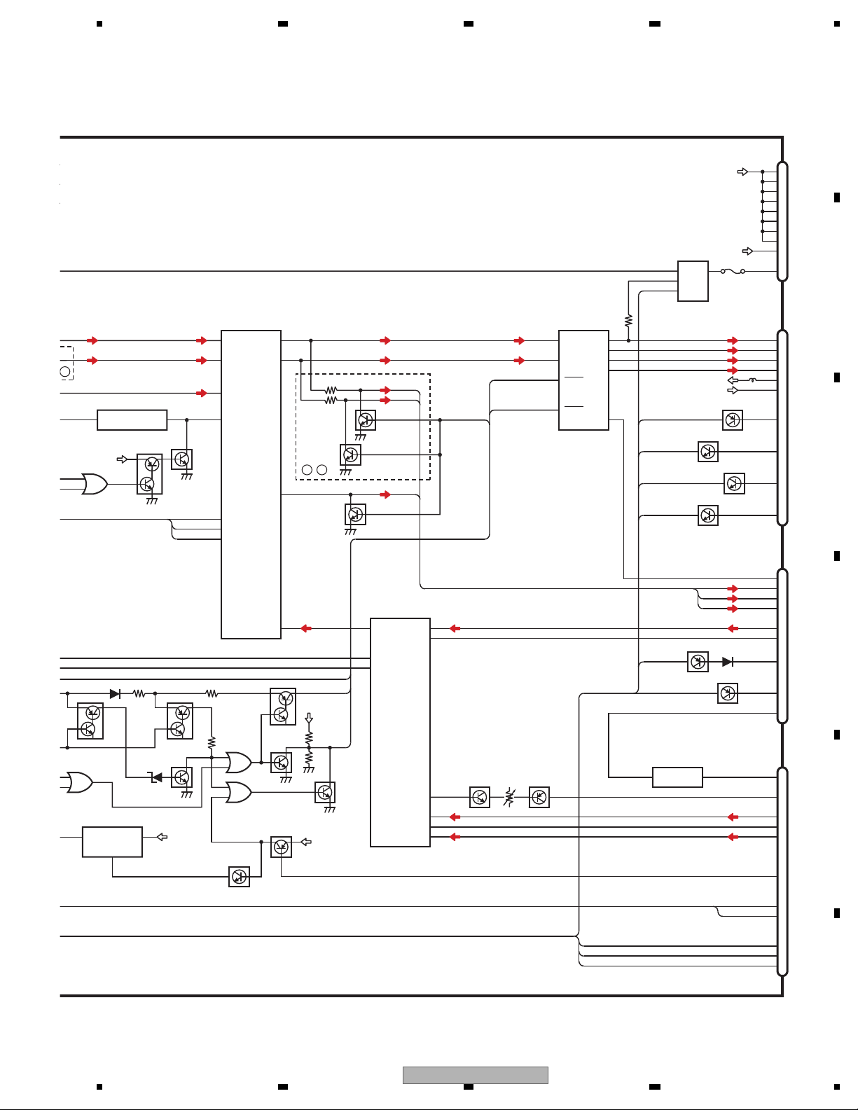
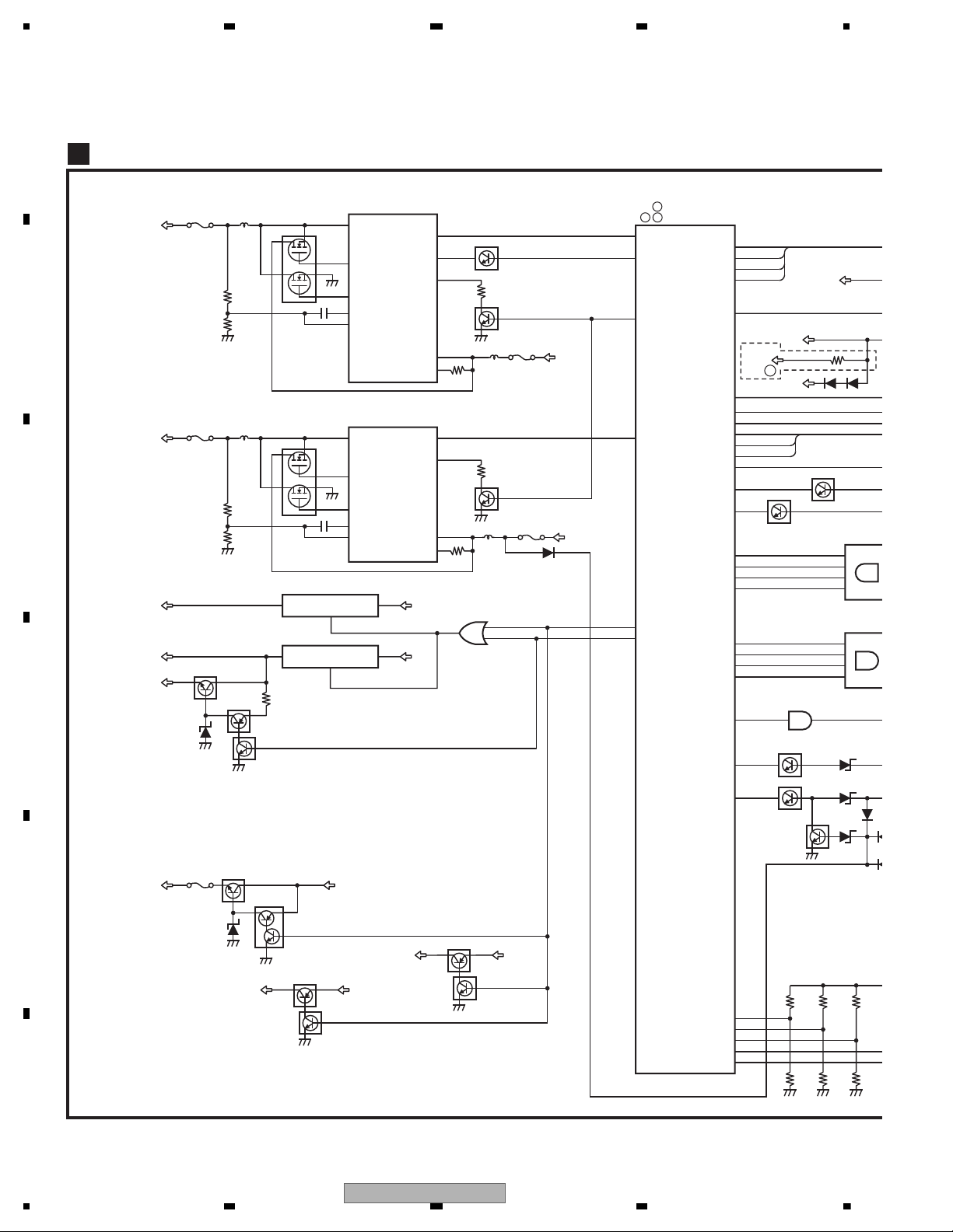
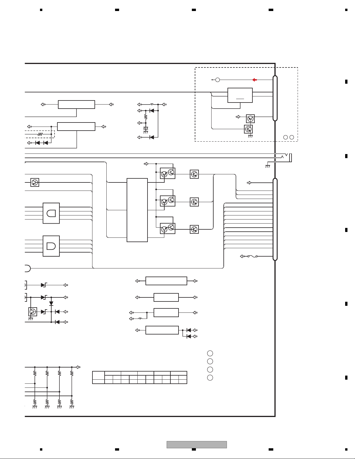
4.2 BLOCK DIAGRAM
to Titan
(NAVIBD)
to CPLD(NAV
GPS Antenna CONN
USB 2.0 Slot*1
RS232CONN*1
Rear Camera CONN
Speaker CONN
Speaker Out
Composite In
Composite In (1)
USB 2.0
GPS Antenna
GPS
Antenna
Radio
Antenna
Composite
Composite
R-sound In
L-sound In
Phone Mute Input
Wire Remote Input
Acc/Bup/ILM
Speed Pulse Input
Parking Signal Input
Reverse Signal Input
Reset
GND
Reset Signal
UART(2)
TMC
Composite In (2)
GUIDANCE (Audio Signal)
Source Audio Signal
CPU Watchdog
An Information of Power off
An Answer of Power off
Reverse Signal
VCC 5 V
Speed Pulse
Control Signal
Video Out CONN
Radio Antenna CONN
Phone Mute CONN
Parking Signal CONN
Wire Remote Input
Reverse Signal Input
Power Supply CONN
Speed Pulse CONN
RF Splitter
I2C
AMP E-vol
SD/MMC Slot
SDIO(1)
U
G
AV
Selector IC
Audio Unit
FM/AM
Tuner
FM
MPX
DARC
Only AVN-Japan
Arrange
Waveform
Arrange
Waveform
Votage
Detecting IC
Votage
Detecting IC
Arrange
Waveform
Arrange
Waveform
LPF
DC/DC Switch
DVD or CD (S10.5 comp2)
System
u-COM
Sence
Digital Out CONN
3RCA CONN
IP-BUS CONN
SD Board
Audio Unit
Rear
Pannel
24
AVIC-F700BT/XS/UC
Page 25
5678
56
7
8
C
D
F
A
B
E
to CPLD(NAVI BD)
Composite In (1)
Composite In (2)
GND
l
Transmitter
Switch
CKS4823-A
5 V In Jack
Digital Out CONN
USB 2.0
H & D Gyro
ADC
I2C(1)
ROM 16-bit
SDIO(1)
133 MHz
USB 2.0
AC97
UART(0)
USP(0)
USB 2.0
GPS Antenna
RS232
I2C(0)
UART(2)
VCC 5 V
Reset Signal
ITU-R BT
601/656
8-bit
Dead Reckoning
G Sensor
GPS Front end
Bluetooth Module
TMC/FM6 Module
BT Antenna
TMC
Mono Out
Speed Pulse
16-bit
Color-TFT
Touch Panel
4-wire
Headphone Out
LED Driver
LVDS RX
5.8” TFT LCD
with
Touch Panel
LVDS TX
Xilinx CPLD
Timing
Control
ADC
Volume
Controller
AuX-in
BT Antenna
Buttons
1. Eject
2. Menu
3. Map
4. Mute
DDR1*2
(16Meg*32)
SLC Flash 256 MB
Video Decoder
Front Panel
Key Pad
Board
600 MHz
LCD Board
Navigation Unit
CPU
Audio Codec
UP to 400 MHz DDR or 166 MHz SDRAM
Enhanced 32 channel GPS base band
24-bit Color-TFT LCD panel interface
8/16-bit HAND flash interface
CMOS/CCD sensor interface
USB OTG 2.0 high-speed interface
ATA-4 interface (UDMA33)
2 slots SD/SDIO/MMC/MMC4.0/CE-ATA
2 CANBus ports
AC97 & I2C Audio CODEC interface
3 Universal Serial Ports (USP) &
3 UARTs
2 SPI interface
2 I2C interface
PWM interface
AVIC-F700BT/XS/UC
25
Page 26
1234
1234
C
D
F
A
B
E
AV UNIT(1/2)
A
FL
ANT1401
FM DISTRIBUTION
VICS/TMC AMP
NAVI UNIT
TMJ1
FM/AM
ANTENNA
Q1421
AV8
FL
Q1401
T1403T1402
T1401
CN1441
Q1441
FM/AM TUNER UNIT
6178
9
3
5
4
FM_ANT
1
AM_ANT
A
CB
VCC
AV8
13
VDD5
VDD_3.3
TU3
SL
CE2
CE1
CK
10
14
DI
DO
TUNSL
23
LchFML
TUNCE2
TUNCE1
TUNCLK
TUNDO
TUNDI
11
18
LDET
RDS_CK
19
20
RDS_DATA
RDS_LOCK
21
RDS_HSLK
HRCK
HLDET
HRDT
HRLK
HRHSLK
Q752
Q753
Q754
Q751
A
HRCK
HLDET
HRDT
HRLK
HRHSLK
ROM_VDD
134
ILLSNS
72
TEIN
78
SELSDA
79
SELSCL
95
VST
96
VDT
97
VCK
FML
IC10
BA4558R
3
GUIDE ISOLAT
GUIDE
ILMSNS
CDL
BDC
IPL
VD8
CD3.3
2
1
VD(7.5V)
9
8
RESET CDRESET
13
LOUT CDL
VDD(3.3V)
CN701
RESET
19
SREMOTE
66
MUTE
85
TUNSL
141
TUNCE2
9
TUNCE1
8
TUNCLK
7
TUNDO
5
TUNDI
6
LDET
26
RCK
25
RDT
17
RDSLK
14
RDS57K
18
XOUT
XIN
X601
20.000MHz
20
22
CDRESET
113
TEMPIN
137
TEMP SENSOR
TH601
103
ASENS
73
FANCONT
CN701
C
TO 2/2
77
NOSELR
GUIDEMUTE
NOSELR
AV8
SYSTEM-uCOM
IC610(1/2)
PEG446A
PEG447A
A
C
B
BRST,BRXEN,BSRQ,BDATA,BSCK
A
AVIC-F700BT/XS/E
B
AVIC-F700BT/XS/U
C
AVIC-F7010BT/XS/
D
TO 2/2
1
3
IC608
BD5335FVE
IC603
TC7SH04FUS1
IC604
TC7S32FU
VOUT
CT
VDD
SRCM
2
4
4
1
2
Q2860
BUP
26
AVIC-F700BT/XS/UC
Page 27
5678
56
7
8
C
D
F
A
B
E
30
LOUT2
19
L4-1
15
L3-1
23
L5-1
AV SELECTOR
IC4171
AN15887A
36
SCL
35
SDA
34
VOUT1
6
IN2_L
IC1016
BA4558RFVM
73
2
IN5+_L
3
IN4+_L
EVOL
IC4271
PML018A
GUIDE ISOLATOR/LPF AMP
MUTE
MUTE
MUTE
10
5
Frout_L
IN3_L
11
FL
RL
Rear_L
12
Pre/SW_L
Q4232
VR4231Q4231
VIDEO BUFFER
VOUT
1
VIN
4BCVIN
BACK CAMERA ISOLATOR
IC4251
NJM2505AF
VCK
VDT
20
CLK
19
DATA
VST
21
STB
43
V4-1
37
V1-1
14
5
12
3
21
23
4
22
SREMOTE
PWR AMP
IC1007
PAL007C
IN2
OUT2+
OUT2-
IN4 OUT4+
OUT4-
25
B_REMOTE
STBY
MUTE
CN1005
8
12
14
5
7
ILMILMSNS
ACC
6
CN1016
BCV
12
BREMBREMOTE
13
ASENS
11
REVREVSNS
9
PKBPKBOUT
Q2880
Q2900
PFL
PRL
RL+
RL-
FL+
CN1000
(1/2)
POWER SUPPLY TERMINALSCORD ASSYNAVI UNIT
OTJ1
NAVI UNIT
SPJ1
27
FRV
FL-
9
5
13
SWL
FL
RL
PFL
PRL
ANTB
16
BUP
Q2870
Q4751
7
IN1-L
Q4333
Q4331
Q4332
CB
C
SWL
POMUTE
29
AANT
GUIDEMUTE
30
GUIDE
32
PKBPKBOUT
42
KMODEKMODEOUT
43
REVREVSNS
44
AUX-LAV2LS
12
AUX-VAV2VIN
NAVIAL
15
VTR1LAV1LS
17
VTR1VAV1VIN
19
TELMUTE
1
TEIN
BCV
23
NaviAL
23
8
KMODEKMODEOUT
Q4752
Q601
MUT
FANV
AV8V
CN1001
2
20
ASENS
FANUP
FANCONT
Q4771
I
Q4776
AV8
4
6
8
10
12
14
16
18
NAVI5V
FU4771
RESETHDRST
4
HDRST
FAN DRIVER
PARKING SENS
REVSNS
ASENS
TELMUTE
KMODE
ILMSNS
Q4314
Q4312
AV8
O 2/2
SREMOTE
POMUTE
RSTMUTE
RSTIN
Q1016(2/2)
Q1016(1/2)
15
3
IC608
BD5335FVE
IC604
C7S32FU
VOUT
CT
VDD
UVDD5
VDD5
SRCMUTE
MUT
4
1
2
Q2863
Q2860
Q2861
Q2864
Q2865
Q2862
AV8
AVIC-F700BT/XS/UC
27
Page 28
1234
1234
C
D
F
A
B
E
NAVI5V
IC4601
TPS5103IDB
9
14
Q4661
VCC_SENSE
RWMSKIP
10
STBY
Q4602
19
18
17
LL
48
NAVICON
49
DCSKIP
88
104
FCONT
BSENS
OUT_U
OUT_D
3
FB
NKBUP
NAVI5V
2
INV
FU4601
FU4602
CD7.5V
IC4641
TPS5103IDB
14
VCC_SENSE
10
STBY
Q4642
19
18
17
LL
58
VDCONT
OUT_U
OUT_D
3
FB
BU
VD8
2
INV
FU4641
FU4642
92
ANTON
ANTB
1
5
Q4601
RT
5
Q4641
RT
DSCKIPCD
36
RX
70
IPPW
71
ASENBO
37
TX
Q4733
Q4731
86
BSENSN
Q4738
139
WREMIN
133
WCONT
AV UNIT(2/2)
A
121
RSTOUT
119
OFFINFO
126
SYSTOC
131
SYSTOCV
117
BATFAULT
120
CPUWDT
118
OFFANS
125
CTOSYS
128
CTOSYSV
124
DVEJKY
112
ROT1
111
ROT0
CTOSYS5
CTOSYSV5
OFFANS5
CPUWDT5
3
3V→5V
IC605
TC74VHCT08
6
8
11
SYSTOCV5
BATFAULT5
SYSTOC5
OFFINFO5
9,10
5V→3V
IC609
TC74VHC08
1,2
4,5
12,13
Q661
Q662
RESET
IC601
TC7SH08FUS1
NAVIC
1,2 4
105
106
107
LEDDT
LEDCK
LEDCS
56
55
51
SIMUKE0
SIMUKE1
SIMUKE4
53
52
SIMUKE2
SIMUKE3
R658 R655 R651
R657 R654 R650
13
VCC
13
VCC
69
SYSPW
67
SWACPW
SWVDD5
VDD5
Q2881
Q2882
SYSPW
3.3V
NAVI3V
Q4753
Q4754
SYSPW
FU4631
ILMV
Q4631
Q4632
BU
Q2811
Q2812
ILMV
42
AV8
VIDEO5
Q2810
BUP
SWACPW
IC2801
BA00CC0WCP-V5
AV8
42
TU3
VT6
IC2830
BA00BC0WFP
TU3
VIDEO5
1
1
SYSPW
SWACPW
SYSPW
SYSTEM-uCOM
IC610(2/2)
PEG446A
PEG447A
C
B
A
50
VT8
4
VICS8
VT6
A
28
AVIC-F700BT/XS/UC
Page 29
5678
56
7
8
C
D
F
A
B
E
BUP3
5 1,3
IC4703
S-L2980A33MC-C6S
VDD5
BUP3
AU4
3,4 1
IC1008
NJM2125F
AV8
AU4
ANTB
15
6
IC2890
TPD1018F
BUP
AANT
BDC
KBUP
Q4732
Q4734
ASENBO
BU BUP
NKBUP
KBUP
NAVIC
+
CD3.3
31
IC4702
NJM2885DL1-33
VDD5
CD3.3
VT6
BU
KBUP
Q4733
NAVIC
CN1021
IPBUS-
IPL+IPL
IPBUS+
7
1
5
IC4721
HA12241FP
6
5
DIN1
ROUT
BUS+
BUS-
ASENBO
8
12TX
RX
8
IPPW
STBY
IP BUS
CN1015
WIRED REMOTE
(Black)
3 1,2
3V→5V
IC605
TC74VHCT08AFTS1
6 4,5
8 9,10
11 12,13
CTOSYSV3
CTOSYS3
SYSTOCV3
SYSTOC3
OFFANS3
CPUWDT3
BATFAULT3
OFFINFO3
FO5
ROT1
ROT0
RESETB
9,10 8
5V→3V
IC609
TC74VHC08FTS1
1,2 3
4,5 6
12,13 11
Q661
4
CN1000
(2/2)
9
ILMR
7
ILMG
6
ILMB
5
EJECTDVEJKY
3
ROT1
17
ROT0
18
RESETB
48
NAVI33V
24
CTOSYSV3
34
CTOSYS3
37
OFFANS
45
WDOG
OFFANS3
CPUWDT3
47
BATTERY-FAULTBATFAULT3
16
SYSTOCV3
35
SYSTOC3
38
OFFINFOOFFINFO3
46
NAVI3V
FU2900
A, B, C
R643
104
R644
NM
SIMUKE4
R646
104
R647
NM
SIMUKE3
R650
104
R651
NM
SIMUKE2
R654
104
R655
NM
SIMUKE1
R657NMR658
104
SIMUKE0
R658 R655 R651 R647 R644
R657 R654 R650 R646 R643
UVDD5
NAVI UNIT
OTJ1
TO 1/2
NKBUP
42
1
IC2820
BA00CC0WCP-V5
KBUP
VT8
ILMR
ILMG
ILMB
ILMV
61
DI AO1
72
CLK AO2
83
LD AO3
Q3604
Q3605
LEDDT
LEDCK
LEDCS
Q3606
Q3601
Q3602
Q3603
RED
GREEN
BLUE
IC3601
M62343FP
RGB LED DRIVER
ILMV
ILMV(LEDSW)
WCONT
WIREIN
3
2
1
VDD5
51
IC4701
BD3931HFP
KBUP
UVDD5
VDD5
A
B
AVIC-F700BT/XS/UC
AVIC-F7010BT/XS/UC
AVIC-F700BT/XS/EW5
C
D
TO 1/2
AVIC-F700BT/XS/UC
29
Page 30
1234
1234
C
D
F
A
B
E
KEYBOARD UNIT
B
RESET
CN801
2
RESET
S801
EJECT
3
EJECT
S804
INT_KEY0
4
ROT1
14
1
2
3A
B
C
Com
Enc-Com
4
7
10
9
PUSH
D
8
5
MENU
S802
MAP
S805
KEY0
5
INT_KEY1
6
ROT0 Phase-B
Phase-A
13
ROTARY COMMANDER
S803
KEY1
7
BL-LED
8
AUX- V
21
AUX- AG
20
AUX-VG VG
AG
22
AUX- L
19
ILMV
9
ILMR
D801
10
ILMG
11
ILMB
R
G
B
12
PUSH
A
C
BD
CN803
3
D815
1
CN802
AV MINI
JACK IN
NAVI UNIT
BTJ2
PANEL UNIT
OTJ2
R
4
L
2
AUX- G
1
V
2,3
1
BT-ANT
ANT801
RF_I/O
30
AVIC-F700BT/XS/UC
Page 31

5678
56
7
8
C
D
F
A
B
E
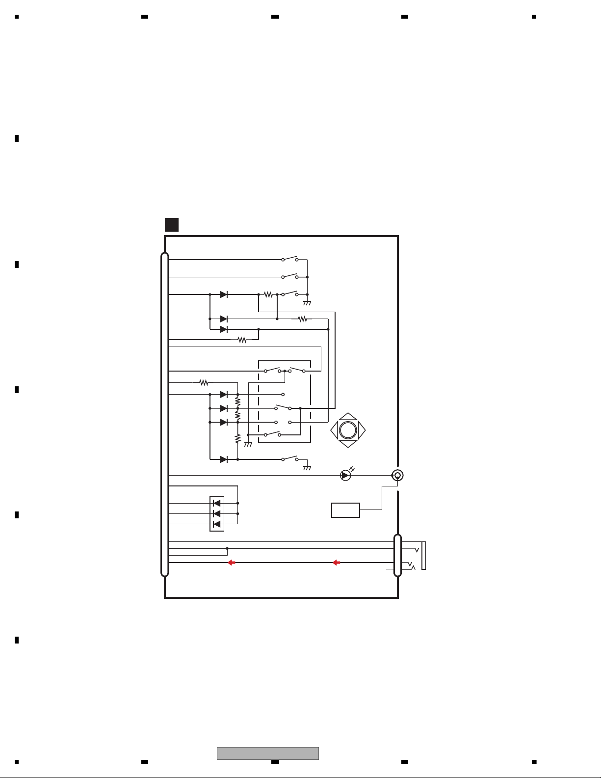
CD CORE UNIT(S10.5COMP2)
C
PICKUP UNIT
(P10.5)(SERVICE)
BRST,BRXEN,BSRQ
CN701
Q101
M
LASER
DIODE
MONITOR
DIODE
S903
DSCSNS
SPINDLE
MOTOR
M
CARRIAGE
MOTOR
LOAD/
LD-
MD
15
5
HOLOGRAM
UNIT
IC301
BA5839FP
IC201
PE5547A
RF-AMP, CD DECODER,
MP3/WMA DECODER,
DIGITAL SERVO /
DATA PROCESSOR
CD
DRIVER
2
VD
VD
13
LOUT
9
CN101
16
SOP
15
SOM
18
LCOP
17
LCOM
21
CLCONT
55
LOUT
9
CONT
TD,FD
AC,BD,F,E
SD,MD
S901
HOME
S904
12EJ
S905
8EJ
LD+
14
141
LD
142
PD
12EJ
CONT
CLCONT
HOME
8
9
43
41
VDD
1
VDD
BDATA,BSCK
Q102
39
/PUEN
VDD
15
5
FOCUS ACT.
TRACKING ACT.
FOP
TOP
2
1
TOP
FOP
11
FOP
14
TOP
2
1
14
8EJ
7
DSCSNS
6
VCC
16
/RESET
8
/RESET
88
VREF
REFO
133
REFOUT
33
FOM
FOM
12
FOM
44
TOM
TOM
13
TOM
22
LOEJ
LOEJ
5
52
50
X201
XTAL
/XTAL
16.93MHz
VDSENS
11
VD
CN701
A
AVIC-F700BT/XS/UC
31
Page 32

1234
1234
C
D
F
A
B
E
4.3 POWER SUPPLY SYSTEM FIGURE
+B
POW
AV UNIT
SYS u-com
M30878FJBGP
VDD5
REGULAR
POWER SUPPLY
5 V
BD3931HFP
HA12241FP
IP-BUS DRIVER
RESET IC
BD5335FVE
NAVI -> SYS
TC74VHCT08T
UVDD5
ROM COLLECTION
S-93C568DOI
BUP 3 V
S-L2980A33MC-C6C
ATT CONTROL
UMD3N*3
DCSKIPCD
FM/AM
TUNER
UNIT
X-2026
VT8(8 V)
BA00CC0WFP
typ 103 mA
max 140 mA
typ 172 mA
max 200 m
A
DISTRIBUTOR
MACHINE
TU3
BA00CC0WFP
SYSPW or
SWACPW
SYSPW
IR REMOTE
RPMS2401-H19E4AV
2 mA2 mA2 mA
SWVDD5
MS5 ->SYS
TC74VHCT
2 m
A
SYS -> MS
TC74VHC08FT
2 mA
1 mA
MAX 45 mA
TYP 32 mA
2 mA
FM/AM Tuner
Front step
am
p
lifie
r
TMC/VICS/MSN/Direct
Tuner Front step amplifier
63 m
A
4 m
A
11 m
A
81 m
A
172 m
A
25.4 mA
25.4 mA
27.3 mA
427 mA
RGB_LED DRIVER
M62343&UMX1N
3 mA
D
B C E
32
AVIC-F700BT/XS/UC
Page 33

5678
56
7
8
C
D
F
A
B
E
POWER SUPPLY
RQ(WDT,IRQ)
TC7WH32FU
3 -> 5AND IPD
TC7SET08FU
RST INV
TC74SH04
2 mA
OR MUTE CIRCUIT
TC7S32FU
2 mA
R
AV SELECTOR
2 mA
MS5 ->SYS
TC74VHCT32T
2 m
A
2 mA
TEMPERATURE CIRCUIT
3 mA
AVIC-F700BT/XS/UC
33
Page 34

1234
1234
C
D
F
A
B
E
D/D
CD 7.5 V(S10.5)
IP_BUS POWER SUPPLY
SW
ASENBO
POWER , AMP
PAL007B
SW FOR ANT +
ANTON
SYSPWR or
SWACPW
AUTO ANTENNA
AV8(8.3 V)
BA00CCOWCP
SWACP
VIDEO ISOLATOR
NJM2505F
typ 19 mA
max 29.0 mA
VIDEO 5 V
VDCONT
D/D
NAVI 5 V
NAVICO
CD 3.3 V
NJM2885DL1-33
MAX 230 mA
TYP 160 mA
CD Source OFF
40 mA
FCONT
FCONT
S10.5(CD)
SYSPW
ILMV 9 V
KMOD TR
PKB SNS
SYSPW
SYS->NAVI
TC7SH08FU
SYS->NAVI
TC74VHCT08
NAVI 3.3 V
ILMV
MAX 1 100 mA
TYP 300 mA
CD Source OFF
20 mA
DCSKIP
121.6 mA
181.1 mA
24 mA
326.7 mA
30 mA
VDD5
VT8
D
B C
E
NAVI, LCD BORD
34
AVIC-F700BT/XS/UC
Page 35

5678
56
7
8
C
D
F
A
B
E
GUIDE MIX
NJM2060V
MUTE CIRCUIT
AU4
NJM2125
CAPTAIN6
AV SELECTOR
AN15887A
PKB SNS
SYS->NAVI
TC74VHCT08FTS1
50 mA
9 mA
1 mA
37 mA
8.4 mA
KEY BORD
AVIC-F700BT/XS/UC
35
Page 36

1234
1234
C
D
F
A
B
E
5. DIAGNOSIS
Acc on (USUALLY Acc ON)
/BSENS
/ASENS
STATUS
MUTE
ASENBO
SREMOTE
SYSPW
DCSKIPCD
ANTON
SWACPW
DCSKIP
BSENSN
RSTOUT
BATFAULT
CPUWDT
OFFINFO
OFFANS
NAVICON
FANCONT
FAN CONTROL
200 ms
EXTERNAL
OUTPUT
AUDIO
CONTROL
NAVI POWER
SUPPLY
CONTROL
NAVI CONTROL
ANTON (Source interlocking
movement, forced OFF)
250 300 ms( SURVEY)
POWER SUPPLY MASK(200 ms
1 sec 2 sec
IP-BUS
PRETREATMENT
IP-BUS SLAVE
CONNECTION CHECK
SOUND MUTE
CONTROL
POWER SUPPLY MASK(200 ms
SENSE SYSTEM
POWER
SUPPLY
CONTROL
IP-BUS
SYSTEM
POWER SUPPLY MASK(200 ms
WAITING FOR SLAVE
POWER SUPPLY
OSCILLATION STOP
STANDBY LOOP
500 ms
(At the time of a reset start)
5.1 OPERATIONAL FLOWCHART
36
AVIC-F700BT/XS/UC
Page 37

5678
56
7
8
C
D
F
A
B
E
8 ms to 16 ms or mor
e
FANCONT(At the time of high temperature
)
16 ms
MAIN LOOP
After mute (300 ms)
(After SYSPWR ON, at least 300 ms. MUTE time is extended to OFFANS Low henceforth.)
AVIC-F700BT/XS/UC
37
Page 38

1234
1234
C
D
F
A
B
E
5.2 ERROR CODE LIST
- Error Messages
If a CD is not operative or stopped during operation due to an error, the error mode is turned on and cause(s) of
the error is indicated with a corresponding number. This arrangement is intended at reducing nonsense calls from
the users and also for facilitating trouble analysis and repair work in servicing.
(1) Basic Indication Method
1) When SERRORM is selected for the CSMOD (CD mode area for the system), error codes are written to DMIN
(minutes display area) and DSEC (seconds display area). The same data is written to DMIN and DSEC. DTNO
remains in blank as before.
2) Head unit display examples
Depending on display capability of LCD used, display will vary as shown below. xx contains the error number.
8-digit display 6-digit display 4-digit display
ERROR-xx ERR-xx E-xx
(2) Error Code List
Code Class Displayed error code Description of the code and potential cause(s)
10 Electricity Carriage Home NG CRG can't be moved to inner diameter.
SERVO LSI Com- CRG can't be moved from inner diameter.
munication Error -> Failure on home switch or CRG move mechanism.
Communication error between microcomputer and SERVO LSI.
11 Electricity Focus Servo NG Focusing not available.
-> Stains on rear side of disc or excessive vibrations on REWRITABLE.
12 Electricity Spindle Lock NG Spindle not locked. Sub-code is strange (not readable).
Subcode NG -> Failure on spindle, stains or damages on disc, or excessive vibrations.
A disc not containing CD-R data is found.
Turned over disc are found, though rarely.
CD signal error.
17 Electricity Setup NG AGC protection doesn't work. Focus can be easily lost.
-> Damages or stains on disc, or excessive vibrations on REWRITABLE.
30 Electricity Search Time Out Failed to reach target address.
-> CRG tracking error or damages on disc.
44 Electricity ALL Skip Skip setting for all track.
(CD-R/RW)
50
Mechanism
CD On Mech Error Mechanical error during CD ON.
-> Defective loading motor, mechanical lock and mechanical sensor.
A0 System Power Supply NG Power (VD) is ground faulted.
-> Failure on SW transistor or power supply (failure on connector).
Remarks: Mechanical errors are not displayed (because a CD is turned off in these errors).
Unreadable TOC does not constitute an error. An intended operation continues in this case.
Upper digits of an error code are subdivided as shown below:
1x: Setup relevant errors, 3x: Search relevant errors, Ax: Other errors.
38
AVIC-F700BT/XS/UC
Page 39

5678
56
7
8
C
D
F
A
B
E
1. TELMUTE
2. DTVVGND
3. RR
4. DTVV
5. RL
6. REARGND
7. FR
8. KMODE
9. FL
10. FRONTGND
11. SWR
12. BREM
13. SWL
14. SWGND
15. VTR1R
16. VTR1RGND
17. VTR1L
18. VTR1LGND
19. VTR1V
20. VTR1VGND
21. REARVOUT
22. GNDV
23. BCV
24. BCVGND
1. FR+
2. RR+
3. FR-
4. RR-
5. FL+
6. RL+
7. FL-
8. RL-
9. PKB
10. PULSE
11. REV
12. ILM
13. AANT
14. ACC
15. GND
16. BUP
1. IPBUS+
2. IPBUSG
3. IPLG
4. NC
5. IPBUS-
6. IPRG
7. IPL+
8. ASENBO
9. IPR+
10. IPR-
11. IPL-
1 3579111315
246810121416
POWER SUPPLY
1 3 5 7 9 11 13 15 1719 2123
2 4 6 8 1012 1416 1820 2224
AV IN/OUT
1234
56 7
8 9 10 11
IP-BUS IN (UC)
USB
MIC IN
GPS ANTENNA
WIRED REMOTE
FM/AM ANTENNA
5.3 CONNECTOR FUNCTION DESCRIPTION
AVIC-F700BT/XS/UC
39
Page 40

1234
1234
C
D
F
A
B
E
5.4 TROUBLESHOOTING
No Power
Key illimination is
lighted?
Check the following signal in the
AV unit.
(BSEN/ASEN/ILM, 8 V Power
supply)
Key illumination is
lighted more than 20
seconds?
LCD backlight is OK?
NAVI5V is OK?
Check the Power supply (D/D
converter) block and Control signal
(48pin NAVICON) of the System
u-com in the AV unit.
LCD unit failure.
Power supply
block for "LCD Panel
unit" is OK?
LCD Panel unit failure.NAVI unit failure.
NAVI3V from the
NAVI unit is OK?
NAVI unit failure.
(NAVI3V is supplied from NAVI
unit and also NAVI3V is
generated from NAVI5V)
NO
YES
NO
YES
NO
(No output)
YES
NO
Key illimination
go off after 20
seconds.
Initial communication error
between NAVI and AV unit.
- Confirm communication line
between 2 unit. (*1)
- Change the NAVI unit
(*1)
Normal operation after ACC ON
- RESETB: High
- OFFINFO: L -> H
- OFFANS: H -> L
- CTOSYS: UART
- SYSTOC: UART
- CPUWDT: L
- BATFAULT: L
Notes:
All siganl mentioned above are control
key signal from System u-com (AV
unit) to NAVI unit.
The "H" voltage is different depends on
the location.
- Port of system u-com: 5 V
- Connector of AV unit: 3 V
YES
No Display
(White or Gray screen)
YES
NO
(No output)
NO
YES
- FLOWCHART
40
AVIC-F700BT/XS/UC
Page 41

5678
56
7
8
C
D
F
A
B
E
LCD BD Side ANAVI BD Side BNAVI BD Side A
Case 1 System can not wake-up.
ACC ON ACC OFF
Pin27: NAVI33V High High This power supply is from NAVI BD to AV BD.
Pin5: OFFINFO High Low This signal is from AV BD(system-ucom) to NAVI BD.
Pin6: OFFANS Low High This signal is from NAVI BD to AV BD(system-ucom).
(High = 3.3 V)
Pin13: SYSTOC Communication line (Sys u-com to NAVI unit)
Pin14: CTOSYS Communication line (NABI unit to Sys u-com)
Pin3,5,7,9,11,13,15,17,19 ACC ON ACC OFF
NAVI 5V 5V 5V power supply is from AV BD to NAVI BD.
Case 2 Navi image can not be displayed on LCD.
Pin1: TFT_ANODE
Pin36: LVDSN Video signal (LVDS) from NAVI to LCD BD. Pin2: TFT_ANODE2
Pin37: LVDSP Video signal (LVDS) from NAVI to LCD BD. Pin6: TFT_CATHODE
Pin7: TFT_CATHODE
Power supply
from LCD BD to
LCD unit
05niP1niP
Pin1
Pin2
Pin19
Pin20
Pin1
Pin74
Chip resistor (0 ohm)
A
B
C
D
E
B
C
D
F
Pin1 Pin10
- DIAGNOSIS POINT
AVIC-F700BT/XS/UC
41
Page 42

1234
1234
C
D
F
A
B
E
Case 3 Touch panel operation doesn't work
Pin1: nYPON
Pin2: nXPON
Pin3: YMON
Pin4: XMON
Pin29: nYPON
Pin30: nXPON
Pin31: YMON
Pin32: XMON
Case 4 Hard Key doesn't work
Pin8: KEY0 KEY (Push, Menu, Right) signal from KEY BD to LCD BD (DC Voltage)
Pin9: KEY1 KEY (MAP, Left, Down ,Up) signal from KEY BD to LCD BD (DC Voltage)
Pin11: ROT0 KEY (Rotary) signal from KEY BD to LCD BD (Pulse waveform)
Pin12: ROT1 KEY (Rotary) signal from KEY BD to LCD BD (Pulse waveform)
Pin33: ROT0 KEY (Rotary) signal from KEY BD to LCD BD (Pulse waveform)
Pin34: ROT1 KEY (Rotary) signal from KEY BD to LCD BD (Pulse waveform)
The signal from touch-panel to LCD BD
(Wavefrom pulse can be mintored while operating touchpanel.)
The signal from LCD BD to NAVI BD
(Wavefrom pulse can be mintored while operating touchpanel.)
Pin1 Pin4
Pin1
Pin74
Pin1
Pin74
05niP1niP
E
A
D
B
42
AVIC-F700BT/XS/UC
Page 43

5678
56
7
8
C
D
F
A
B
E
Case 5 Audio (NAVI SOURCE) or Guide voice (BEEP sound) is NG.
Pin19: GUI_P Guidance or BEEP sound
Pin28: NAVI L Audio Lch
Pin30: NAVI R Audio Rch
Pin29,31: GND
05niP1niP
B
AVIC-F700BT/XS/UC
43
Page 44

1234
1234
C
D
F
A
B
E
6. SERVICE MODE
1. Test mode menu selection method
The main keyboard cannot be used for this operation.
Double-click the touch panel directly.
2. Test mode activation method
1. Copy a "TestMode" folder under “TestMode” folder on GGV1322 to a SD card.
Note: "TestMode" folder must be on the SD card root.
2. Download a ID file from the Service Site and copy the file to the "TestMode" folder on the SD card.
3. Insert the SD card into the main unit.
4. Turn ACC ON.
5. The test mode menu is displayed.
<< Enter the test mode in the set procedure. >>
When the set procedure is followed (Procedure OK)
Start screen
Jig No : GGV1322
6.1 TEST MODE
44
AVIC-F700BT/XS/UC
Page 45

5678
56
7
8
C
D
F
A
B
E
3. Test mode menu
No. Test Item Test Content
1 Audio Playback of audio
2 AV Test Not for service
3 TEL Test Not for service
4 GPS CHK GPS receiver test
5 GYRO Not for this model (F900 series only)
6 Flash ROM Flash ROM read/write test
7 TMC/VICS FM multiplex error test
8 Dir CMD Not for service
9 Graphics Graphics test
10 Ver Info Display version information of software, mecha, and microcomputers.
11 Touch Correction and test of Touch Panel
12 Key Test Not for service
13 Port Test Display states such as parking and reverse.
14 Voice Test Not for service
15 Memory Not for service
16 MSN-Direct Not for service
17 USB Test Not for service
18 DTV Test Not for service
19 SD Test SD card test
20 EQ Flat/Vo Not for service
21 RGB Illumin Not for service
22 BT Test Not for service
23 Screen Not for service
24 BAK CTL Adjustment of the LCD backlight
AVIC-F700BT/XS/UC
45
Page 46

1234
1234
C
D
F
A
B
E
Audio Test Screen
Gps Viewer Execution Screen
Audio Test Mode
Starttest
<< Key Operation >>
[Play]
• • • Play
[Stop]
• • • Stop
[Guidance]
• • • Output of guidance
[Stereo]
• • • Output of stereo
[OK]
• • • Terminate Audio Test.
<< Operation method >>
1. Select ‘Start Type’. Normally, ‘Hot’.
2. Press ‘Start’ to start the test.
46
AVIC-F700BT/XS/UC
Page 47

5678
56
7
8
C
D
F
A
B
E
Tracking
<< Operation method >>
1. When GPS Running is red, press ‘hot’.
<< Operation method >>
1. When GPS Running is green, the test is started.
2. When Valid Position is green, the measurement is successfully conducted.
Signal
<< Operation method >>
1. The screen will be in this state if the test is not started.
2. To start the test, press ‘hot’.
AVIC-F700BT/XS/UC
47
Page 48

1234
1234
C
D
F
A
B
E
Sats
<< Operation method >>
1. The screen will be in this state if the test starts.
2. When the blue color bar appears, GPS signal is locked.
<< Operation method >>
1. The screen will be in this state if the test is not started.
2. To start the test, refer to ‘Start test’ tab.
<< Operation method >>
1. When the test starts and a satellite is started to be acquired, the screen will be in this state.
Red
• • • Not acquired. Yellow • • • Already acquired. Green • • • Acquired and data obtained.
48
AVIC-F700BT/XS/UC
Page 49

5678
56
7
8
C
D
F
A
B
E
NAND Flash test mode start screen
Write files Conduct a write test to NAND Flash disc.
Read/verify files Conduct a read test to NAND Flash disc. Notes) It will take time by test completion.
Delete Files Conduct a deletion test to NAND Flash disc.
Format disc Conduct a formatting test to NAND Flash disc. Notes) Only the test area of the Flash disc
will be formatted.
TMC measurement selection screen
GpsTmcDemo
<< Test Content >>
The TMC error rate can be measured.
The frequency can be changed by tapping ‘<’ or ‘>’.
The test can be terminated by tapping the left ‘x’ mark.
AVIC-F700BT/XS/UC
49
Page 50

1234
1234
C
D
F
A
B
E
Graphics Test start screen
Start screen
<< Operation method >>
1. The screen will be in this state after started.
2. Press ‘Test’ to start the test.
<< Operation method >>
1. The menu appears when ‘Test’ is pressed. Select the item to test.
<< Operation method >>
1. To terminate the test, press ‘File’ and then ‘Exit’.
50
AVIC-F700BT/XS/UC
Page 51

5678
56
7
8
C
D
F
A
B
E
Version Information screen
Start screen
<< Key operation >>
[Get Version]
• • • Display the version of Bootloader, GPS, and BSP.
[Get Application Version]
[uCOM Ver]
[Get DVD-Mecha]
[Clear]
[GetDeviceID]
• • • Display the microcomputer version and ROM Collection version.
• • • Display the DVD and CD mecha version.
• • • Clear the display of the version of microcomputer, ROM, and mecha.
• • • Display the device ID.
Touch Panel Test screen
Start screen
<< Key operation >>
[Calibration]
[Touch panel test]
• • • Conduct calibration.
• • • Conduct touch panel test.
• • • Display the version of each application.
AVIC-F700BT/XS/UC
51
Page 52

1234
1234
C
D
F
A
B
E
Calibration
Touch Panel Test
<< Key operation >>
Touch panel calibration can be conducted by tapping five ‘+’ marks.
<< Key operation >>
A line appears when a line is drawn by a finger on the touch panel.
The test can be terminated by pressing the top right ‘x’ mark.
52
AVIC-F700BT/XS/UC
Page 53

5678
56
7
8
C
D
F
A
B
E
Port Test screen
Start screen
<< Key operation >>
[Get signal]
• • • Display the states of Parking brake, Reverse, K-Mode, and Speed Pulse.
The states of Illumination, Cellular mute, OPTSNS, Antenna control, and Remote control are displayed
automatically.
[Clear]
• • • Clear the display.
[High]
• • • Not for service
[Low]
• • • Not for service
SD Card Test screen
Start screen
<< Key operation >>
[Start]
• • • Start the test.
AVIC-F700BT/XS/UC
53
Page 54

1234
1234
C
D
F
A
B
E
Backlight Test screen
Error screen
Start screen
<< Key operation >>
[Backlight Off]
• • • The backlight turns off.
Notes) No operation can be conducted after this operation.
Make a recovery by turning ACC OFF ON.
[Backlight on]
• • • The backlight turns on.
[Set]
• • • The brightness of the backlight can be changed.
This is the state when an error occurred in the test.
54
AVIC-F700BT/XS/UC
Page 55

5678
56
7
8
C
D
F
A
B
E
Backlight Level setting method
<< Key operation >>
1. Tap the edit box at the left of the Set button to make it active.
2. Then, tap the bottom left of the screen, and the screen will be as shown below. Tap ‘Keyboard’.
<< Key operation >>
3. When the keyboard appears, tap the edit box again to make it active. Then input by keyboard becomes possible.
Enter a desired number and tap ‘Set’ to change the brightness of the backlight.
AVIC-F700BT/XS/UC
55
Page 56

1234
1234
C
D
F
A
B
E
6.2 CD TEST MODE
1) Cautions on adjustments
In this product the single voltage (3.3 V) is used for the
regulator. The reference voltage is the REFO1 (1.65 V)
instead of the GND.
If you should mistakenly short the REFO1 with the GND
during adjustment, accurate voltage will not be obtained,
and the servo’s misoperation will apply excessive shock
to the pickup. To avoid such problems:
a. Do not mix up the REFO1 with the GND when
connecting the (-) probe of measuring instruments.
Especially on an oscilloscope, avoid connecting the (-)
probe for CH1 to the GND.
b. In many cases, measuring instruments have the same
potential as that for the (-) probe. Be sure to set the
measuring instruments to the floating state.
c. If you have mistakenly connected the REFO1 to the GND,
turn off the regulator or the power immediately.
Before mounting and removing filters or leads for
adjustment, be sure to turn off the regulator.
For stable circuit operation, keep the mechanism
operating for about one minute or more after the
regulator is turned on.
In the test mode, any software protections will not
work. Avoid applying any mechanical or electrical
shock to the mechanism during adjustment.
The RFI and RFO signals with a wide frequency range
are easy to oscillate. When observing the signals,
insert a resistor of 1k ohms in series.
The load and eject operation is not guarantied with the
mechanism upside down. If the mechanism is blocked
due to mistaken eject operation, reset the product or
turn off and on the ACC to restore it.
2) Test mode
This mode is used to adjust the CD mechanism module.
To exit from the test mode.
Turn off the ACC and back up.
Notes:
a. During ejection, do not press any other keys than the
EJECT key until the loaded disc is ejected.
b. If you have pressed the (→) key or (←) key during focus
search, turn off the power immediately to protect the
actuator from damage caused by the lens stuck.
c. For the TR jump modes except 100TR, the track jump
operation will continue even if the key is released.
d. For the CRG move and 100TR jump modes, the tracking
loop will be closed at the same time when the key is
released.
e. When the power is turned off and on, the jump mode
is reset to the single TR (91), the RF amp gain is set to 0 dB,
and the auto-adjustment values are reset to the default
settings.
56
AVIC-F700BT/XS/UC
Page 57

5678
56
7
8
C
D
F
A
B
E
W
MM-14-23-01
E REUCAUJ
CN
PKB
(1), (2) and (3) are invisible buttons
In this screen, press long the areas (1), (2) and (3) that
display the test mode selection screen
by implementing the operations below in order
.
Detailed procedur
e
Step1 change the screen to source OFF screen
Step2 press the area of (1) lon
g
Step3 press the area of (2) lon
g
Step4 press the area of (3) lon
g
* When the operation above is normally implemented,
BEEP sound 1 is output.
If the operation is completed successfully,
the screen shifts to test mode screen after (3) is pressed long
The test mode is released by ACC-OFF operation
.
Source PlateOFF
SlaveTestMode
DVD(CD) region display
DVD(CD) debug display
DVD(CD) touch direct display
Back
Shift to selected test mode.
Map
AVIC-F700BT/XS/UC
57
Page 58

1234
1234
C
D
F
A
B
E
[Key]
Contents
Display
Test Mode In
Source On
TRK MIN SEC
[07]
Power On
(T.Offset is adjusted)
TRK MIN SEC
00 00 00
[03]
Power On
(T.Offset is not adjusted)
99 99 99
[02]
RF AMP
Gain switching
GG GG GG
*1
[04]
SPINDLE
Speed switching
SP SP SP
*9
[03]
Focus Close
S curve check
TRK MIN SEC
91 91 91
[06]
Focus Mode switching
0X 0X 0X
*2
[01]
Tracking Servo
Close
00 00 00
or 99 99 99
[08]
CRG +
[02]
Self-adjusting
switching
TRK MIN SEC
?? ?? ??
*3*8
[09]
CRG -
*8
[07]
Power Off
TRK MIN SEC
[07]
Power Off
TRK MIN SEC
[07]
Power Off
TRK MIN SEC
[07]
Power Off
TRK MIN SEC
[01]
T.Close & AGC
Applicable servomechanism
TRK MIN SEC
?tr ?min ?sec
[06] [03]
RF AGC /
RF AGC coefficient display
[08]
CRG +
8X 8X 8X
or 9X 9X 9X
[02]
T.Balance adjustment /
T.BAL coefficient display
TRK MIN SEC
?? ?? ??
[09]
CRG -T.Close
Applicable servomechanism
?? ?? ??
[01]
F,T,RF AGC
F.Bias display switching
TRK MIN SEC
TRK MIN SEC
TRK MIN SEC
TRK MIN SEC
?tr ?min ?sec
TRK MIN SEC
[03] [06]
CRG/TR jump
value switching
[08]
CRG/TR Jump +
[02]
Tracking Open
[09]
CRG/TR Jump -
?tr ?min ?sec
TRK MIN SEC
TRK MIN SEC
TRK MIN SEC
?tr ?min ?sec
00 00 00
or 99 99 99
TRK MIN SEC
TRK MIN SEC
?tr ?min ?sec
8X 8X 8X
or 9X 9X 9X
8X 8X 8X
or 9X 9X 9X
00 00 00
or 99 99 99
TRK MIN SEC
?tr ?min ?sec?? ?? ??
*7
F,T AGC / F.Bias
RF AGC
8X 8X 8X
or 9X 9X 9X
[02]
Tracking Open
*6
*5
*4 *4
Operation
[Key]
Test Mode
[07] Power On/Off
[08]
CRG + / TR Jump +
(Direction of the external surface)
[09]
CRG - / TR Jump (Direction of the internal surface)
[01] T. CLS & AGC & Applicable servomechanism /
AGC,AGC display setting
[02] RF Gain switching / Offset adjustment display /
T.Balance adjustment / T. Open
[03] F. Close,S Curve / Rough Servo and RF AGC /
F,T,RF AGC
[04]
SPDL 1X/2X switching
As for the double speed(2x), audio output cannot be
supported.
[5]
Error Rate measurement
ON : ERR 30Counts Start
BER display data[%]
[6] F. Mode switching / Tracking Close / CRG•TR
Jump Switching
*) • After the [Eject] key is pressed keys other than the [Eject] key should not be pressed, until disc ejection is complete.
• When the key [2] or [3] is pressed during the Focus Search, the power supply should be immediately turned off (otherwise the lens
sticks to Wall, causing the actuator to be damaged).
• In the case of TR jump other than to 100TR, the function shall continue to be processed even if the TR jump key is released. As for
the CRG Move and 100TR Jump, the mechanism shall be set to the Tracking Close mode when the key is released.
• When the power is turned on/off the jump mode is reset to the Single TR (91) while the gain of the RFAMP is reset to 0 dB. At the
same time all the self-adjusting values shall return to the default setting.
*10
TRK MIN SEC
[05]
Gop Mode
Gop Mode switching
OL OL OL
- Flow Chart
*1) TYP → + 6 dB → + 12 dB
TRK
MIN
SEC
TRK06MIN06SEC
06
TRK12MIN12SEC
12
*2) Focus Close
→ S Curve check setting → F EQ measurement setting
TRK00MIN00SEC
00
TRK
01
MIN01SEC
01
TRK02MIN02SEC
02
(
TRK99MIN99SEC
99)
*3) F.Offset Display → RF.Offset → T.Offset Display → Switch to the
order of the original display
*4) 1TR/4TR/10TR/32TR/100TR
*5) Single
→ 4TR → 10TR → 32TR → 100TR → CRG Move
9x(8x):91(81) 92(82) 93(83) 94(84) 95(85) 96(86)
*6) Only at the time of CRG move, 100TR jump
*7) TRK/MIN/SEC
→ F.AGC → T.AGC Gain → F.Bias → RF AGC
*8) CRG motor voltage = 2 [V]
*9) TYP (1X)
→ 2X → 1X
TRK
MIN
SEC
TRK
22
MIN22SEC
22
TRK11MIN11SEC
11
*10) OFF(TYP)
→ FORCUS → TRACKING
TRK
MIN
SEC
TRK
70
MIN70SEC
70
TRK71MIN71SEC
71
• As for the double speed (2x), audio output cannot be supported
58
AVIC-F700BT/XS/UC
Page 59

5678
56
7
8
C
D
F
A
B
E
UBOOT Upgrade
1. Copy the Uboot files named as “uboot.bin” and “uboot.cks” to the SD/MMC card
2. Inset SD/MMC card to the Main Unit at first, then enter the Uboot interface.
3. Select ““3=UBOOT Upgrade” item in Uboot menu, then select ““1=UBOOT by SD/MMC” item
in “UBOOT Upgrade” menu and execute.
UBOOT Upgrade
0=WINCE Upgrade 0=UBOOT by USB
1=GPS Tools 1=UBOOT by SD/MMC
2=BT Tools 2=Exit
3=UBOOT Upgrade Choice: 1
4=Memory Tools
5=Other Tools
Coice: 0
<Uboot Menu> <UBOOT Upgrade Menu>
UBOOT Upgrade UBOOT Upgrade
0=UBOOT by USB 0=UBOOT by USB
1=UBOOT by SD/MMC 1=UBOOT by SD/MMC
2=Exit 2=Exit
Choice: 1 Choice: 1
Star Erase & Write UT!!
UT Upgrade O
K
Star Erase & Write UT!! Please restart your device!!
Read Progress : 31% Read process 100%
<UBOOT Upgrade Menu:Progress Screen> <UBOOT Upgrade Menu:Finish Screen>
4. After the menu of “UBOOT Upgrade” show “UT Upgrade OK”, restart the device.
WINCE Image Upgrade
1. Copy the image files named as “winceimg.bin” and “winceimg.cks” to the SD/MMC card.
2. Inset SD/MMC card to the Main Unit at first, then enter the Uboot interface.
3. Select “0=WINCE Upgrade” item in Uboot menu, then select “1=WINCE b
y
SD/MMC” item
in “WINCE Upgrade” menu and execute.
WINCE Upgrade
0=WINCE Upgrade 0=WINCE by SD/MMC (Format)
1=GPS Tools 1=WINCE by SD/MMC
2=BT Tools 2=WINCE by USB (Format)
3=UBOOT Upgrade 3=WINCE by USB
4=Memory Tools 4=Exit
5=Other Tools Coice: 1
Coice: 0
<Uboot Menu> <WINCE Upgrade Menu>
WINCE Upgrade WINCE Upgrade
0=WINCE by SD/MMC (Format) 0=WINCE by SD/MMC (Format)
1=WINCE by SD/MMC 1=WINCE by SD/MMC
2=WINCE by USB (Format) 2=WINCE by USB (Format)
3=WINCE by USB 3=WINCE by USB
4=Exit 4=Exit
Coice: 1 Coice: 1
Image Region
Checksum = 0x64463447
Read Progress : 31% CE Upgrade OK
Please restart your device!!
<WINCE Upgrade Menu:Progress Screen> <WINCE Upgrade Menu:Finish Screen>
4. After the menu of “WINCE Upgrade” show “CE Upgrade OK”, restart the device.
6.3 uBOOT MENU
AVIC-F700BT/XS/UC
59
Page 60

1234
1234
C
D
F
A
B
E
6.4 USING THE TEST DISC
Test Disc 1 Start Screen Specification
Test Disc 1 Start
1. Copy all files under “Test Disc1” folder on GGV1322 to a SD card.
2. Download a ID file from the Service Site and copy the file to the SD card.
3. Insert the Test Disc in the SD card and turn ACC OFF ON. Then, the test disc starts.
The test can be terminated by turning ACC OFF. After turning ACC OFF, remove the SD card.
Test Disc 1 Start Screen
MIC Test
<< Operation method >>
1. This screen appears when the Test Disc is activated.
2. Tap ‘E-MIC’ to start the test.
<< Operation method >>
1. This screen appears when the test is started.
2. Put a sound into the microphone while this screen is shown. The sound is recorded.
Jig No : GGV1322
60
AVIC-F700BT/XS/UC
Page 61

5678
56
7
8
C
D
F
A
B
E
<< Operation method >>
1. When this screen appears, the recorded sound is played ‘loudly’.
Notes) The sound volume cannot be adjusted.
<< Operation method >>
1. When this screen appears, the recorded sound is played ‘quietly’.
Notes) The sound volume cannot be adjusted.
<< Operation method >>
1. When this screen appears, the recorded sound is muted.
Notes) The sound volume cannot be adjusted.
AVIC-F700BT/XS/UC
61
Page 62

1234
1234
C
D
F
A
B
E
<< Operation method >>
1. When the test finishes, this screen appears.
2. To proceed to the next test, tap ‘OK’. To conduct MIC Test again, tap ‘Retry’.
<< Operation method>>
1. This screen appears when the Test Disc is activated.
If you tap "GPS_TTFF", the test is started.
GPS Test
<< Operation method >>
1. When the test is started, this screen is displayed.
When you terminate the test in the way, tap the "Exit".
62
AVIC-F700BT/XS/UC
Page 63

5678
56
7
8
C
D
F
A
B
E
<< Operation method >>
When the positioning is terminated within one minute, the test is completed successfully,
and this screen is displayed.
If you implement the test again, tap the "Retry".
If you go to next step, tap "OK".
Version Check
<< Operation method >>
1. This screen appears when the Test Disc is activated.
2. When ‘Version’ is tapped, the test starts.
If the "Reality" corresponds to "Plan", the result becomes "OK".
AVIC-F700BT/XS/UC
63
Page 64

1234
1234
C
D
F
A
B
E
<< Operation method >>
If the test result is "OK", the blue screen is displayed.
"Reality" is each version on actual machine and the "Plan" is the version information
described in "Information.txt" of SD card.
<< Operation method >>
If the test result is "NG", the red screen is displayed.
64
AVIC-F700BT/XS/UC
Page 65

5678
56
7
8
C
D
F
A
B
E
Jig No : GGV1322
Test Disc 2 Start Screen Specification
Test Disc 2 Start
1. Copy all files under “Test Disc 2” folder on GGV1322 to a SD card.
2. Download a ID file from the Service Site and copy the file to the SD card.
3. Insert the SD card into the Main Unit and turn ACC OFF ON. Then, the test disc starts.
The test can be terminated by turning ACC OFF. After turning ACC OFF, remove the SD card.
Test Disc 2 Start Screen
The user data is deleted
<< Operation method >>
1. This screen appears when the Test Disc is activated.
2. If you tap the "Restore", the user data is deleted.
<< Operation method >>
If the deletion is terminated, this screen is displayed.
Notes:) "Splash screen setting" is not back to default after performing this function.
Please set the "Splash screen setting", before performing this function.
AVIC-F700BT/XS/UC
65
Page 66

1234
1234
C
D
F
A
B
E
7. DISASSEMBLY
1
1 1
Fig.1
Removing the Case (Fig.1)
Remove the two screws and then remove
the Case.
Note)
To remove the screws, use jig No. GGK1068.
Case
NOTE) While the photograph shown is slightly different from this model in shape, the disassembly
procedure is the same.
1
1
1
1
1
Fig.2
Remove the four screws.
Disconnect the connector on the back
and then remove the CD Mechanism Module.
Removing the CD Mechanism Module (Fig.2)
CD Mechanism Module
66
AVIC-F700BT/XS/UC
Page 67

5678
56
7
8
C
D
F
A
B
E
1
2
1
2
1
1
1
1
2
2
Fig.4
Remove the five screws.
Disconnect the four connectors and then
remove the Navi Unit.
Removing the Navi Unit (Fig.4)
Navi Unit
1
2
3
(Right side)
2
1
1
1
3
2
3
3
1
1
1
(Top side)
(Left side)
Fig.3
Removing the Monitor Assy (Fig.3)
Remove the six screws.
Release the two latches.
Disconnect the three connectors and then
remove the Monitor Assy.
Monitor Assy
Monitor Assy
Monitor Assy
2
AVIC-F700BT/XS/UC
67
Page 68

1234
1234
C
D
F
A
B
E
1
2
3
Remove the screw.
Remove the six screws and then remove
the AV Unit.
5
6
4
6
6
2
6
5
2
4
6
6
2
2
3
2
2
1
1
2
4 4
6
(Right side)
(Left side)
Fig.5
Remove the two screws.
Remove the seven screws.
Disconnect the connector and then
remove the Heat Sink.
Remove the three screws and then
remove the Chassis(Upper).
Removing the AV Unit (Fig.5)
AV Unit
Chassis(upper)
Chassis(Upper)
Heat Sink
Remove the FFC(CDE8550).
Remove the FFC(CDE8552).
Remove the cord assy(CDE8393).
Remove the cord assy(CDH1381).
68
AVIC-F700BT/XS/UC
Page 69

5678
56
7
8
C
D
F
A
B
E
1
2
3
1
2
3
1
3 3
3
2
2
3
3
2 2 2
2
2
SD Unit
3
2
3
3
3
1
1
1
2
1
Fig.6
Fig.7
Removing the Panel Unit (Fig.6)
Removing the Keyboard Unit (Fig.7)
Panel Unit
LCD Module Assy
Keyboard Unit
Remove the four screws.
Release the five latches and then remove
the LCD Module Assy.
Remove the four screws and then remove
the Keyboard Unit.
Remove the screw and connector
and then remove the SD Unit.
Disconnect the four connectors.
Remove the five screws and then remove
the Panel Unit.
1
AVIC-F700BT/XS/UC
69
Page 70

1234
1234
C
D
F
A
B
E
A
A
B
B
Upper Frame
Lower Frame
B
B
B
B
a
Damper
Carriage Mechanism
Damper
Do not squeeze this area.
- How to hold the Mechanism Unit
- Removing the Upper and Lower Frames
1. With a disc inserted and clamped in the
mechanism, remove the two Springs (A), the
six Springs (B), and the four Screws.
2. Tur n the Upper Frame using the part "a" as
a pivot, and remove the Upper Frame.
3. While lifting the Carriage Mechanism,
remo
ve it from the three Dampers.
Caution: When assembling, be sure to apply
some alcohol to the Dampers and assemble
the mechanism in a clamped state.
1. Hold the Upper and Lower Frames.
2. Do not hold the front portion of the Upper
Frame, because it is not ve
ry solid.
70
AVIC-F700BT/XS/UC
Page 71

5678
56
7
8
C
D
F
A
B
E
- How to remove the CD Core Unit
1. Apply Shorting Solder to the flexible cable of
the Pickup, and disconnect it from the
connector.
2. Unsolder the four leads, and loosen the
Screw.
3. Remove the CD Core Unit.
Caution: When assembling the CD Core Unit,
assemble it with the SW in a clamped state
so as not to damage it.
Shorting Solder
Screw
CD Core Unit
Solder
- How to remove the Pickup Unit
1. Make the system in the carriage mechanism mode, and have it clamped.
2. Remove the CD Core Unit and remove the leads from the Inner Holder.
3. Remove the Poly Washer, Change Arm, and Pickup Lock Arm.
4. While releasing from the hook of the Inner Holder, lift the end of the Feed Screw.
Caution: When assemb
ling, move the Planet Gear to the load/eject position before setting the Feed Screw in the Inner
Holder.
Assemble the sub unit side of the Pickup, taking the plate (Chassis) in-between. When treating the leads of the Load
iage Motor Assy, do not make them loose over the Feed Screw.
Carr
Poly Washer
Pickup Lock Arm
Feed Screw
Change Arm
Inner Holder
AVIC-F700BT/XS/UC
Planet Gear
Pickup Rack
Chassis
Pickup
71
Page 72

1234
1234
C
D
F
A
B
E
• Notes on disassembly
• When separating the MONITOR ASSY from the MAIN UNIT ASSY, do so slowly.
Two FFCs (CDE8554, CDE8556) and one CODE ASSY (CDE8559) are connected. The strength of the joint part
of the code and terminals of CDE8559 (CODE ASSY for Bluetooth to connect the keyboard unit and navi unit)
is weak, it may break or the code may extend.
Remove after peeling off the tape of CDE8556 and the shield.
• When demounting LCD PANEL ASSY from the grille, be careful not to bend LCD plate (CND4319) as there are
snap fits on the right and left. Demount LCD PANEL ASSY by extending snap fits on the grille side.
CDE8559
Snap fit
2 place
Do not bend CND4319
Remove snap fits by extending
them on the grille side using
tweezers or bamboo tweezers.
Do not bend CND4319
Actually does the CODE ASSY (CDE8559) to a left connector of a round inclosing.
*
72
AVIC-F700BT/XS/UC
Page 73

5678
56
7
8
C
D
F
A
B
E
• Be sure to remove the MONITOR ASSY after removing the CD mecha.
If the procedure is done oppositely, the FFC (CDE8556) connecting the MONITOR ASSY and the MAIN UNIT
ASSY will be damaged. At assembly, be sure to fix the MONITOR ASSY first and then fix the CD mecha. If it is
done oppositely, the FFC (CDE8556) cannot be folded as intended under the CD mecha.
CDE8556
• When connecting the code assy connecting 1F AV UNIT and 2F NAVI UNIT (CDH1381) on NAVI UNIT side, do
so as shown below.
OK
Horizontal
NG
Vertical
• The code assy connecting 1F AV UNIT and 2F NAVI UNIT (CDE8393) shall be fitted on the back side of the
choke coil (CTH1347) after 1F Chassis Unit and 2F Chassis Unit are fixed, as shown below.
CDE8393
AVIC-F700BT/XS/UC
CTH1347
73
Page 74

1234
1234
C
D
F
A
B
E
• When mounting KNOB ASSY (CXC8994, CXC8995) in the MONITOR ASSY, be careful to don't destroy
encoder part.
• Since two case (CNB3472) fixing screws are ‘TORX tamper’ (tamper-proof screws with a projection in
TORX), a special tool is required.
TORX screwdriver(T8) : GGK1068
CSX1135 shaft of an encoder
CXC8994
CXC8995
Mark 1 (T8 size)
M2.6 thread
74
AVIC-F700BT/XS/UC
Page 75

5678
56
7
8
C
D
F
A
B
E
CD CORE UNIT(S10.5COMP2)
Note :
The grating angle of the PU unit cannot be adjusted after the PU unit is changed. The PU unit in the CD mechanism
module is adjusted on the production line to match the CD mechanism module and is thus the best adjusted PU
unit for the CD mechanism module. Changing the PU unit is thus best considered as a last resort. However, if the
PU unit must be changed, the grating should be checked using the procedure below.
Purpose :
To check that the grating is within an acceptable range when the PU unit is changed.
Symptoms of Mal-adjustment :
If the grating is off by a large amount symptoms such as being unable to close tracking, being unable to perform
track search operations, or taking a long time for track searching.
Method :
Measuring Equipment
Measuring Points
Oscilloscope, Two L.P.F.
E, F, REFO1
Disc TCD-782
Mode TEST MODE
Checking Procedure
1. In test mode, load the disc and switch the 3 V regulator on.
2. Using the k ey 08 and key 09, move the PU unit to the innermost track.
3. Press key 03 to close focus, the display should read "91". Press key 02 to implement the
tracking balance adjustment the display should now read "81". Press key 3. The display will change,
returning to "81" on the fourth press.
4. As shown in the diagram above, monitor the LPF outputs using the oscilloscope and check that the phase
difference is within 75 degrees. Refer to the photographs supplied to determine the phase angle.
5. If the phase difference is determined to be greater than 75 degrees try changing the PU unit to see if there is any
improvement. If, after trying this a number of times, the grating angle does not become less than 75 degrees then the
mechanism should be judged to be at fault.
Note
Because of eccentricity in the disc and a slight misalignment of the clamping center the grating waveform may be
seen to "wobble" ( the phase difference changes as the disc rotates). The angle specified above indicates the
average angle.
Hint
Reloading the disc changes the clamp position and may decrease the "wobble".
100 kohm
390 pF
100 kohm
390 pF
E
VREF
F
VREF
Xch Ych
L.P.F.
L.P.F.
Oscilloscope
FE
REFO1
8. EACH SETTING AND ADJUSTMENT
8.1 CHECKING THE GRATING AFTER CHANGING THE PICKUP UNIT
AVIC-F700BT/XS/UC
75
Page 76

1234
1234
C
D
F
A
B
E
Grating waveform
45 degrees
0 degrees
75 degrees
60 degrees
30 degrees
90 degrees
Ech → Xch 20 mV/div, AC
Fch → Ych 20 mV/div, AC
76
AVIC-F700BT/XS/UC
Page 77

5678
56
7
8
C
D
F
A
B
E
- Adjustment point
AV UNIT(SIDE A)
AV UNIT(SIDE B)
VR4231
V1VG(GND)
V1V
FRV
FRG
1
CN1016
AV CONNECTOR
8.2 AV UNIT ADJUSTMENT
AVIC-F700BT/XS/UC
77
Page 78

1234
1234
C
D
F
A
B
E
point
SpecsAdjusting
Masuring
instruments
VR4231
1.00 V ±0.02 Vp-p
Measure between the sync tip and 100
Oscilloscope
IRE (wave top).
Symptoms with poor adjustment.
Over level:
Luminance is too high.
Under level:
Luminance is too low.
Output signal
(Measurement point,wave pattern)
Measurement point:
FRV FRG (GND)
(To measure the AV Unit only, connect
1.4 kohm between TP FRV and FRG.)
other conditions)
(Input test pin,specs,
Mode Input signal
item
AV UNIT ADJUSTMENT
StepAdjustment
TP V1V, V1VG (GND)
100 IRE
VTR1
AV selector
adjustment
1 Video level
1.0 Vp-p
(Input via 75 ohm)
(white100%)
78
AVIC-F700BT/XS/UC
Page 79

5678
56
7
8
C
D
F
A
B
E
8.3 FLICKER ADJUSTMENT
Signal for Flicker adjustment…
Select “Graphics” -> “Flicer Adjustment”
in the Test Mode.
(Input a signal for alternate white and black line.
The luminance level of the input signal : 50%)
.langis%001etihwtupnIgnigA1
Leave for more than 30 minutes in operation
mode.
directions.
Adjustment item Measurement point Adjustment point The contents of adjustment Remarks
FLICKER ADJUSTMENT
2 Flicker adjustment Screen LCVR1 Adjust the flicker level to minimum from all
AVIC-F700BT/XS/UC
79
Page 80

1234
1234
C
D
F
A
B
E
9. EXPLODED VIEWS AND PARTS LIST
NOTES : Parts marked by " * " are generally unavailable because they are not in our Master Spare Parts List.
The > mark found on some component parts indicates the importance of the safety factor of the part.
Therefore, when replacing, be sure to use parts of identical designation.
Screw adjacent to mark on the product are used for disassembly.
For the applying amount of lubricants or glue, follow the instructions in this manual.
(In the case of no amount instructions,apply as you think it appropriate.)
""
9.1 PACKING
80
AVIC-F700BT/XS/UC
Page 81

5678
56
7
8
C
D
F
A
B
E
(1) PACKING SECTION PARTS LIST
Mark
Mark No. Description Part No.
1 Unit Box See Contrast table(2)
2 Contain Box See Contrast table(2)
3 Protector See Contrast table(2)
4 Protector See Contrast table(2)
5 Screw Assy See Contrast table(2)
6 Screw BMZ50P060FTC
* 7 Polyethylene Bag CEG-127
8 Screw See Contrast table(2)
9 Polyethylene Bag CEG1116
10 Sub Unit Box CHG6491
11 Connector CKX1049
12 Seal CNN2515
13 Pen CNV8969
14 CD-ROM See Contrast table(2)
15 Microphone Assy CPM1064
16 Clip Holder CZN5471
17 Microphone Holder CZN5472
18 Cushion CZN5473
* 19 Microphone CZX5059
No. Description Part No.
20 GPS Antenna Assy CXC8574
21 Attachment Assy CEA4636
22 Water Proof Pad CZN7150
23 Sheet CZN7151
24 •••••
25 Polyethylene Bag See Contrast table(2)
26 Panel See Contrast table(2)
27 Cord CDE6825
28 Cord Assy See Contrast table(2)
29 Cord Assy See Contrast table(2)
30 Cord Assy See Contrast table(2)
31-1 Installation Manual See Contrast table(2)
31-2 Caution Card See Contrast table(2)
* 31-3 Registration Card See Contrast table(2)
* 31-4 Warranty Card See Contrast table(2)
31-5 Owner's Manual
* 31-6 Passport See Contrast table(2)
* 31-7 Caution Card See Contrast table(2)
See Owner’s manual parts list(3)
(2) CONTRAST TABLE
AVIC-F700BT/XS/UC, AVIC-F7010BT/XS/UC and AVIC-F700BT/XS/EW5 are constructed the same except for the
following:
Mark No. Description AVIC-F700BT/XS/UC AVIC-F7010BT/XS/UC AVIC-F700BT/XS/EW5
1 Unit Box CHG6484 CHG6573 CHG6482
2 Contain Box CHL6484 CHL6573 CHL6482
3 Protector CHP3552 CHP3552 CHP3550
4 Protector CHP3553 CHP3553 CHP3551
5 Screw Assy CEA3797 CEA3797 CEA7395
8 Screw CMZ50P060FTC(x8) CMZ50P060FTC(x8) CMZ50P060FTC(x4)
14 CD-ROM Not Used Not Used CPJ1262
25 Polyethylene Bag CEG1402 CEG1402 CEG1401
26 Panel Not Used Not Used CNS8665
28 Cord Assy CDP1137 CDP1137 Not Used
29 Cord Assy Not Used Not Used CDP1138
30 Cord Assy CDP1143 CDP1143 CDP1092
31-1 Installation Manual CRD4335 CRD4335 CRD4336
31-2 Caution Card CRP1310 CRP1310 Not Used
* 31-3 Registration Card CRY1271 CRY1271 Not Used
* 31-4 Warranty Card CRY1246 CRY1246 CRY1265
* 31-6 Passport Not Used Not Used CRY1268
* 31-7 Caution Card CRP1376 CRP1376 CRP1375
Installation Manual
Part No. Language
CRD4335 English, French
CRD4336 English, Spanish, German, French, Italian, Dutch
AVIC-F700BT/XS/UC
81
Page 82

1234
1234
C
D
F
A
B
E
(3) OWNER’S MANUAL PARTS LIST
AVIC-F700BT/XS/UC AVIC-F7010BT/XS/UC AVIC-F700BT/XS/EW5
Part No. Language Part No. Language Part No. Language
CRB2684 English CRB2684 English CRB2700 English
CRB2685 French CRB2685 French CRB2701 Spanish
CRB2686 English CRB2686 English CRB2702 German
CRB2703 French
CRB2687 French CRB2687 French
CRB2704 Italian
CRB2705 Dutch
CRB2706 English
CRB2707 Spanish
CRB2708 German
CRB2709 French
CRB2710 Italian
CRB2711 Dutch
82
AVIC-F700BT/XS/UC
Page 83

5678
56
7
8
C
D
F
A
B
E
AVIC-F700BT/XS/UC
83
Page 84

1234
1234
C
D
F
A
B
E
9.2 EXTERIOR(1)
C
A
B
B
C
D
D
E
E
A
84
AVIC-F700BT/XS/UC
Page 85

5678
56
7
8
C
D
F
A
B
E
(1) EXTERIOR(1) SECTION PARTS LIST
Mark
Mark No. Description Part No.
1 Screw BMZ26P050FTC
No. Description Part No.
25 Holder CND3759
2 Screw CBA2145
3 FFC CDE8556
4 Case CNB3472
5 Card CNW1231
26 Holder CND4319
27 Insulator CNN2044
28 Insulator CNN2045
29 LCD Module CWX3611
6 Screw BMZ26P050FTC
30 Panel Unit CWX3651
7 Screw BPZ20P080FTC
8 Button(MENU, MAP) CAI1707
9 Button(RESET, EJECT) CAI1708
10 Screw(M2 x 3) CBA1797
31 Screw PMB20P040FTC
32 Knob Unit See Contrast table(2)
33 Spring YBL5013
34 Grille Unit See Contrast table(2)
11 FFC CDE8554
12 FFC CDE8555
13 Cord Assy CDE8559
14 Cover CNN2046
15 Lighting Conductor CNV9902
35 Screw IMS26P040FTC
36 Holder See Contrast table(2)
37 Holder See Contrast table(2)
38 Screw See Contrast table(2)
39 Screw See Contrast table(2)
16 Holder CNV9903
40 Label See Contrast table(2)
17 Touch Panel CSX1136
18 Jack(CN802) CKN1049
19 Connector(CN803) CKS5749
20 Connector(CN801) CKS5862
21 Antenna(ANT801) CTX1095
41 Gasket CNN2501
42 Gasket CNN2533
43 Insulator CNN2534
44 Cushion See Contrast table(2)
45 Gasket See Contrast table(2)
22 SD Unit CWX3652
23 Screw(M2 x 2) CBA1771
46 Insulator See Contrast table(2)
24 Holder CND3758
(2) CONTRAST TABLE
AVIC-F700BT/XS/UC, AVIC-F7010BT/XS/UC and AVIC-F700BT/XS/EW5 are constructed the same except for the
following:
Mark No. Description AVIC-F700BT/XS/UC AVIC-F7010BT/XS/UC AVIC-F700BT/XS/EW5
32 Knob Unit CXC8995 CXC8995 CXC8994
34 Grille Unit CXC8990 CXC9776 CXC8991
36 Holder Not Used Not Used CND3430
37 Holder Not Used Not Used CND3431
38 Screw Not Used Not Used BMZ30P060FTB
39 Screw Not Used Not Used CMZ50P060FTC
40 Label Not Used Not Used CAN5448
44 Cushion CNN2723 CNN2723 Not Used
45 Gasket CNN2724 CNN2724 Not Used
46 Insulator CNN2725 CNN2725 Not Used
AVIC-F700BT/XS/UC
85
Page 86

1234
1234
C
D
F
A
B
E
9.3 EXTERIOR(2)
E
E
B
C
D
D
A
C
A
F
F
(A)
(A) GYH1031(Mylay tape)
* Hold the flexible cable to the shield on the Navi Unit.
86
AVIC-F700BT/XS/UC
Page 87

5678
56
7
8
C
D
F
A
B
E
(1) EXTERIOR(2) SECTION PARTS LIST
Mark
Mark No. Description Part No.
1 Screw ASZ26P050FTC
2 Screw BMZ26P050FTC
3 Screw BMZ26P160FTB
No. Description Part No.
13 Insulator CNN2042
14 Insulator CNN2043
15 Sheet CNN2281
4 Screw BSZ26P050FTB
5 Screw(M2.6 x 12) CBA2102
16 Sheet CNN2294
17 Heat Sink CNR1944
6 Cord Assy CDE8393
7 FFC CDE8550
8 FFC CDE8552
18 Navi Unit(U1) See Contrast table(2)
19 Chassis Unit CXC8981
20 CD Mechanism Module(S10.5) CXK5763
9 Cord Assy CDE8561
10 Chassis CNA3042
21 Fan Motor CXM1320
22 Cord Assy See Contrast table(2)
11 Cover CND3917
12 Bracket CND4564
23 Gasket CNN2529
(2) CONTRAST TABLE
AVIC-F700BT/XS/UC, AVIC-F7010BT/XS/UC and AVIC-F700BT/XS/EW5 are constructed the same except for the
following:
Mark No. Description AVIC-F700BT/XS/UC AVIC-F7010BT/XS/UC AVIC-F700BT/XS/EW5
18 Navi Unit(U1) CWX3641 CWX3641 CWX3639
22 Cord Assy Not Used Not Used CDH1381
AVIC-F700BT/XS/UC
87
Page 88

1234
1234
C
D
F
A
B
E
9.4 EXTERIOR(3)
A
EW5 MODEL
UC MODEL
EW5 MODEL
UC MODEL
88
AVIC-F700BT/XS/UC
Page 89

5678
56
7
8
C
D
F
A
B
E
(1) EXTERIOR(3) SECTION PARTS LIST
Mark
Mark No. Description Part No.
1 AV Unit See Contrast table(2)
2 Screw BMZ26P060FTC
> 3 Fuse(10 A) CEK1208
4 Connector(CN1016) CKM1460
5 Plug(CN1005) CKM1550
No. Description Part No.
19 Shield CND4563
20 Sheet CNM9805
21 FM/AM Tuner Unit(Y1461) See Contrast table(2)
22 Holder CND4324
23 Shield Unit CXC8983
6 Jack(CN1015) CKN1042
7 Connector(CN1021) See Contrast table(2)
24 Pin Jack(CN1441) See Contrast table(2)
25 Shield See Contrast table(2)
8 Connector(CN1001) CKS4674
9 Connector(CN701) CKS4808
10 Connector(CN1000) CKS5732
26 IC(IC1007) PAL007C
27 IC(IC2801, IC2820) BA00CC0WCP-V5
28 Cord Assy See Contrast table(2)
11 Antenna Jack(ANT1401) CKX1060
12 Holder CNC9921
29 Cap CNV6727
30 Cord Assy See Contrast table(2)
13 Shield CND3004
14 Holder CND3181
15 Holder CND3693
31 Terminal Cover See Contrast table(2)
32 Cord Assy See Contrast table(2)
33 Cord CDE6825
16 Holder CND3695
17 Holder See Contrast table(2)
34 Cap CNS1472
35 Resistor RS1/2PMF102J
18 Shield CND4320
(2) CONTRAST TABLE
AVIC-F700BT/XS/UC, AVIC-F7010BT/XS/UC and AVIC-F700BT/XS/EW5 are constructed the same except for the
following:
Mark No. Description AVIC-F700BT/XS/UC AVIC-F7010BT/XS/UC AVIC-F700BT/XS/EW5
1 AV Unit CWN3170 CWN3170 CWN3168
7 Connector(CN1021) CKS3408 CKS3408 Not Used
17 Holder CND4314 CND4314 CND4315
21
24 Pin Jack(CN1441) Not Used Not Used CKX1046
25 Shield Not Used Not Used CND3769
28 Cord Assy CDP1143 CDP1143 CDP1092
30 Cord Assy Not Used Not Used CDP1138
31 Terminal Cover Not Used Not Used CKX-003
32 Cord Assy CDP1137 CDP1137 Not Used
FM/AM Tuner Unit(Y1461)
CWE2098 CWE2098 CWE2127
AVIC-F700BT/XS/UC
89
Page 90

1234
1234
C
D
F
A
B
E
9.5 CD MECHANISM MODULE
90
AVIC-F700BT/XS/UC
Page 91

5678
56
7
8
C
D
F
A
B
E
CD MECHANISM MODULE SECTION PARTS LIST
Mark
Mark No. Description Part No.
1 CD Core Unit(S10.5COMP2) CWX3514
No. Description Part No.
50 Rack CNV8342
2 Connector(CN101) CKS4911
3 Connector(CN701) CKS4808
4 Screw BMZ20P025FTC
5 Screw BSZ20P040FTC
51 Roller CNV8343
52 Holder CNV8344
53 Arm CNV8345
54 Guide CNV8347
6 Screw(M2 x 3) CBA1511
55 Arm CNV8348
7 Screw(M2 x 4) CBA1835
8 Washer CBF1038
9 •••••
10 Spring CBH2609
56 Arm CNV8349
57 Arm CNV8350
58 Clamper CNV8365
59 Arm CNV8386
11 Spring CBH2612
12 Spring CBH2614
13 Spring CBH2616
14 Spring CBH2617
15 Spring CBH2620
60 Guide CNV8396
61 Arm CNV9521
62 Collar CNV8447
63 Motor Unit(M2) CXC4026
64 Arm Unit CXC4027
16 Spring CBH2855
65 Chassis Unit CXC4028
17 Spring CBH2937
18 Spring CBH2735
19 Spring CBH2854
20 Spring CBH2642
21 Spring CBH2856
66 Gear Unit CXC4029
67 Frame Unit CXC4031
68 Motor Unit(M1) CXC7134
69 Screw Unit CXC6359
70 Screw JFZ20P025FTC
22 Spring CBH2857
23 Spring CBH2860
24 Spring CBH2861
25 Spring CBL1686
71 Screw JGZ17P022FTC
72 Washer YE20FTC
73 Pickup Unit(P10.5)(Service) CXX1942
74 Screw IMS26P030FTC
26 Arm CND1909
27 Frame CND2582
28 Bracket CND2583
29 Arm CND2584
30 Lever CND2585
31 Arm CND2586
32 Bracket CND2587
33 Arm CND2588
34 Lever CND2589
35 Holder CNV9522
36 Gear CNV7207
37 Gear CNV9513
38 Gear CNV7209
39 Gear CNV9514
40 Gear CNV9515
41 Gear CNV9516
42 Rack CNV9517
43 Arm CNV7216
44 Roller CNV8189
45 Gear CNV9518
46 Guide CNV9519
47 Gear CNV7595
48 Guide CNV9520
49 Arm CNV7805
AVIC-F700BT/XS/UC
91
Page 92

1234
1234
C
D
F
A
B
E
10. SCHEMATIC DIAGRAM
A-a A-b
A-a
A-b
A-b
A-a
Large size
SCH diagram
Guide page
Detailed page
Note: When ordering service parts, be sure to refer to " EXPLODED VIEWS AND PARTS LIST" or
"ELECTRICAL PARTS LIST".
1/6
A
A-a
1/6
GUIDE
CPUWDT3
SYSTOC3
ROT1
OFFINFO3
SYSTOCV3
OFFANS3
ROT1
RESETB
HDRST
DVEJKY
ROT0
BATFAULT3
AV2RG
AV2RS
RESETB
NAVIAR
HDRST
AV2LS
DVEJKY
CTOSYS3
OFFANS3
OPTSNS
KMODEOUT
OFFINFO3
CPUWDT3
REVSNS
OPTON
CTOSYSV3
PKBOUT
ILMR
ILMG
ILMB
ILMV
FRV
ROT0
AV2VIN
AV2VG
AV2LG
NAVIAL
MONVBS
GUIDEMUTE
VICSON
SREMOTE
SYSPW
AV2RS
CTOSYSV3
SYSTOCV3
SYSTOC3
CTOSYS3
ASENS
ANTON
NAVIRG
NAVILG
FRVGND
GUIDEG
ILMSNS
SRCMUTE
AV2RG
AV2LS
TU3
VIDEO5
FANV
NAVI3V
BATFAULT3
VT6
DCSKIPCD
NAVI3V
NAVI5V
AV8
AV8
AV8
AV8
SWACPW
NFCONT
NFCONT
VT8
C2804
R1
C2811
R1
SYSPW
TU3
BATFAULT3
NAVI5GND
C1022
R1
100/16
C2810
ILMGND
GNDV
CTOSYSV3
Q2810
2SD1760F5
D2802
RB060L-40
R2801
10K
GNDD
GNDA
GNDFM
GUIDEG
ROT0
SYSTOC3
R2940
0R0
DNGMLIGLIVAN
GNDRF
FANGND
100/16
C2801
C1021
R001
C1020
R001
NAVIRG
ROT1
GNDFM
R2804
100K
NAVIRG
OPTSNS
TU3
100/16
C2820
HDRST
100/16
C2830
SRCMUTE
FANGND
AV8
AV8
ASENS
FANGND
DTC114EUA
Q2812
C2821
R01
GNDD
BA00CC0WCP-V5
IC2801
Vadj:1.225V
1
CTL
2
VCC
3
GND
4
VOUT
5
ADJ
D2810
UDZS5R6(B)
VIDEO5
R2811
470
BA00CC0WCP-V5
IC2820
Vadj:1.225V
1
CTL
2
VCC
3
GND
4
VOUT
5
ADJ
D2821
RB060L-40
SREMOTE
GNDV
SWACPW
GNDA
C2812
R1
GNDRF
SYSTOCV3
AV2RG
GNDV
NAVI5GND
GNDD
AV2RS
NAVI5V
ANTON
GNDD
FANGND
R2803
2R2K
C2831
R01
OFFANS3
FANGND
NAVILG
R2946
OPTON
VICSON
DVEJKY
FRVGND
GNDA
CPUWDT3
NAVI5GND
C2802
R001
GNDA
NAVI3GND
VI5
R2802
2R7K
CN1000
1
2
3
4
5
6
7
8
9
10
11
12
13
14
15
16
17
18
19
20
21
22
23
24
25
26
27
28
29
30
31
32
33
34
35
36
37
38
39
40
41
42
43
44
45
46
47
48
49
50
CN1001
1
2345678
9
1011121314151617181920
C2833
R1
FRVGND
CTOSYS3
GNDV
GUIDEG
ILMGND
AV8
RESETB
GNDD
NAVI3GND
C2823
R1
GNDD
GNDA
R2810
0R0
DTA114EUA
Q2811
ILMSNS
VT6
OFFINFO3
VT8
GNDD
R2834
100K
R2832
2R2K
R2822
2R2K
FANV
ILG
EJT
RES
ILMB
ILMG
ILMR
ILMV
AUR
AURG
AUL
AULG
AUVG
AUV
ROT1
ROTO
NARG
NAR
NALG
NAL
N33V
FRG
FRV
BCGN
BCVN
GMUTE
GUIG
GUI
GSY1
CTSV
STCV
GSY2
CTN
STC
GSY3
OPON
OPSN
PKN
KMB
RVN
OFAN
OFIN
WDOG
RESB
PCHG
PLN
R2947
R2945
R2944
R2943
R2948
R2949
R2950
R2951
0R0
R2952
0R0
R2953
0R0
R2954
0R0
R2960
0R0
R2961
0R0
R2962
0R0
R2963
0R0
R2964
0R0
R2967
0R0
R2968
0R0
R2969
0R0
R2970
0R0
R2971
0R0
R2972
0R0
R2973
0R0
R2976
0R0
R2977
0R0
R2978
0R0
R2979
0R0
R2980
0R0
R2981
0R0
R2982
0R0
R2959
0R0
NC1
NFC
SWVDD5
R2941
100
R2942
100
BFA R1016
0R0
R2820
2R2K
R2821
10K
D2822
BA00BC0WFP
IC2830
1VC2
VIN3GND4VDD
5
C
R2830
3R6K
R2831
100
D2831
RR264M-400
GNDD
VICS8
VICS5
VISC8
VISC5
R2823
1M
DCSKIPCD
D2824
1SR154-400
D2823
1SR154-400
D2825
1SS400G
NAVI3V
GNDA
R2833
0R0
C2805
R1
C2800
R001
FU2900
CEK1276
250mA
NFCONT
8.3V
VT8
GND
ILMGND
EJECT
RESET
ILMB
ILMGILMG
ILMR
ILMV(LEDSW)
NC
AUX-R
AUX-RG
AUX-L
ROT1
AUX-VG
AUX-LG
AUX-V
GND
NaviARG
ROT0
BATTERY_FAULT
BCVGND
OPTSNS
GNDSYS
GNDSYS
GUIDE
PKB
GNDSYS
CTOSYSV3
FRVGND
SYSTOCV3
GUIDEMUTE
OPTON
GUIDEG
BCV
FRV
PULSE
OFFINFO
OFFANS
KMODE
WDOG
RESETB
PCHNG
REV
NaviAR
NaviALG
NaviAL
VIDEO5
NFCONT
NAVI33V
5.0V
SYSTOC3
CTOSYS3
NAVI5V
NAVI5V
NAVGND
NAVGND
FANV
FANGND
8.3V
3.3V
AV8
TU3
NAVI5V
NAVI5V
NAVGND
NAVGND
AV8V GND
AV8V
NAVI5V
NAVI5V
NAVI5V
NAVI5V
NAVGND
NAVGND
NAVGND
NAVGND
EW5
8.3V
8.0V
6.5V
6.5V 6.5V
3.3V
8.0V
8.3V
5.0V
8.3V
8.3V
V0.5V0.5
5.0V
5.0V
5.0V
5.0V
5.0V
5.0V
5.0V
5.0V
5.0V
8.3V
5.0V
8.3V 8.3V
8.3V
5.0V
>
3/6
A
2/6
A
3/6
A
6/6
A
4/6
A
Decimal points for resistor
and capacitor fixed values
are expressed as :
2.2
t 2R2
0.022
t R022
Symbol indicates a resistor.
No differentiation is made between chip resistors and
discrete resistors.
NOTE :
Symbol indicates a capacitor.
No differentiation is made between chip capacitors and
discrete capacitors.
to NAVI UNIT
SPJ1
10.1 AV UNIT(PS/IF SECTION)(GUIDE PAGE)
92
AVIC-F700BT/XS/UC
Page 93

5678
56
7
8
C
D
F
A
B
E
1/6
A
A-b
1/6
RR
RR+
PKB
FL+
ASENS
FR-
ILMSNS
ANTON
SRCMUTE
FR+
SREMOTE
REVSNS
FANUP
SREMOTE
OFFMUTE
RL-
FR
FL-
FL
BREMOTE
RL+
RL
RR-
VICSON
AV2RS
ASENS
ANTON
SRCMUTE
GUIDEMUTE
MONVBS
NAVILG
AV2RG
NAVIRG
AV2LG
AV2VG
AV2LS
AV2VIN
NAVIAR
NAVIAL
GUIDE
GUIDEG
FRV
FRVGND
RSTMUTE
KMODEOUT
FANUP
PKBOUT
PKB
ANTON
ILMB
ILMR
ILMG
POMUTE
BREMOTE
FRFLRR
RL
ILMV
RL+
FL+
FR+
FL-
RL-
SYSPW
FR-
RR+
RR-
KBUP
SYSPW
DCSKIPCD
NAVI3V
AV8
AV8
NFCONT
BUP
GNDA
C2804
R1
R2881
4R7K
(1/4W)
BUP2
IC1007
PAL007C
1
2
3
4
5
6
7
8
9
10
11
12
13
14
15
16
17
18
19
20
21
22
23
24
25
FR
Q2863
UMD2N
2E
1
2B
2
1C
3
1E
4
5
1B
6
2C
ILMG
GNDD
R2873
4R7K
GND1
ANTON
R2902
1K
(1/4W)
R2901
100K
R2903
4R7K
(1/4W)
R2875
4R7K
(1/4W)
GNDD
D2802
RB060L-40
DTC114EUA
Q2880
C2932
2R2
(2125)
GNDD
GNDD
AV2LS
GUIDEMUTE
D2862
DAN202U
NAVIRG
GNDD
GNDD
GNDD
C2926
1
FRVGND
DTC114EUA
Q2864
R2910
47K
33/10
C2862
IC2890
TPD1018F
1
OUT
2
GND1
3
GND2
4
GND3
5
VDD
6
IN
7
GND4
8
GND5
9
GND6
10
DIAG
R2900
47K
ILMR
L2871
C2882
R001
C2861
R1
C2931
1
Q2861
UMD2N
2E
1
2B
2
1C
3
1E
4
5
1B
6
2C
GNDD
BUP
C2922
1
(2125)
R2804
100K
KMODEOUT
GNDD
C2925
AV2LG
Q2860
UMD2N
2E
1
2B
2
1C
3
1E
4
5
1B
6
2C
D2860
MA111
GNDD
FANUP
GNDD
47/16
C2860
KB1
IL1
GNDD
SRCMUTE
L2930
KBUP
C2901
R1
CN1005
1
2
3
4
5
6
7
8
9
10
11
12
13
14
15
16
10000/16
C2910
3300/16
C2935
NAVIAL
VDD5
ASENS
NAVIAR
C2872
R001
C2890
R1
RSTMUTE
ILMV
MONVBS
FRV
C2924
R1
DTC124EUA
Q2865
C2921
C2923
GNDD
AV2VG
L2872
D2863
DAN202U
D2821
RB060L-40
NAVILG
ILMB
C2871
R001
C2920
D2900
HZU8R2(B1)
R2870
47K
MUT
GUIDE
R2874
1K
(1/4W)
ISN
GNDD
BREMOTE
PKB
PKBOUT
D2910
KS926S2
FL
AV2RG
Q2870
2SC4116
Q2862
2SC4081
C2881
1
C2892
R001
AV2RS
D2861
UDZS8R2(B)
ANTON
GNDD
R2880
10K
R2872
1K
AV2VIN
VICSON
C2891
R001
D2890
1SR154-400
C2927
D2891
1SR154-400
R2865
1K
(1/10W)
100/25C2929
C2933
2R2
(3216)
R2882
1K
(1/4W)
RR
R2871
100K
POMUTE
D2874
PTZ18A
R2925
10K
C2928
1617181920
C2833
R1
RL
R2924
10K
D2880
1SR154-400
GUIDEG
R2926
10K
D2870
UDZS5R1(B)
C2870
R001
C2823
R1
BUP1
GND2
C2930
R1
10/16
C2934
Q2900
2SC4116
D2930
ST70-27F
10000/16
C2911
10000/16
C2912
DTC114EUA
Q2881
2SA1576A
Q2882
R2834
100K
D2911
RB060L-40
R2912
4R7
R2913
4R7
D2912
KS926S2
GNDD
NKBUP
R2911
47K
GNDD
AC2
KB2
RV2
MUB
ACC
AANT
ILM
REV
PLS
PKB
RL-
FL-
RL+
FL+
RR-
FR-
RR+
FR+
SWVDD5
R2860
390
R2861
390
R2863
22K
R2862
47K
R2864
10K
R2868
220
R2866
10K
R2867
10K
R2869
100
R2884
4R7K
R2883
4R7K
D2822
DAN202U
D2831
RR264M-400
R2823
1M
NAVIC
D2825
1SS400G
NAVI3V
MTB
GNDA
R2920
0R0
R2921
0R0
R2922
0R0
R2923
0R0
NFCONT
R4802
0R0
R4801
0R0
GNDRF
GNDRF
GNDRF
PWR AMP
ILM
AANT
ACC
GND
IN4
S-GND
REV
IN2
PKB
PW.GND1
IN1
PW.GND2
TAB
PW.GND4
PW.GND3
VCC1/2
OUT2+
STBY
Vehicle I/F
OUT2-
OUT4-
MUTE
OUT4+
VCC3/4
OUT3-
OUT3+
SVR
OUT1+
OUT1-
PULSE
B_REMOTE
AC GND
IN3
AV8
BUP
AANT
sensing "low voltage"
or "reset"
emergency MUTE
NAVI5V
NAVI5V
NAVGND
AV8V GND
AV8V
1/4W1/4W
RL+
FL+
RR-
FR-
RL-
RR+
FL-
FR+
AV SECTION
ASENS
ILMSNS
PKB
UCEW5
6.5V
14.4V
14.4V
14.4V
5.0V
5.0V
5.0V
5.0V
V3.8V3.8
8.3V
5.0V
5.0V
600uH
2/6
A
6/6
A
5/6
A
6/6
A
6/6
A
AV UNIT(PS/IF SECTION)
1/6
A
The > mark found on some component parts indicates
the importance of the safety factor of the part.
Therefore, when replacing, be sure to use parts of
identical designation.
AVIC-F700BT/XS/UC
93
Page 94

1234
1234
C
D
F
A
B
E
A-a A-b
A-b
1/6
ASENS
ILMSNS
ANTON
REVSNS
FANUP
RL+
FL+
FR+
FL-
RL-
FR-
RR+
RR-
KBUP
DCSKIPCD
BUP
R2881
4R7K
(1/4W)
BUP2
1
R2873
4R7K
GND1
R2902
1K
(1/4W)
R2901
100K
R2903
4R7K
(1/4W)
DTC114EUA
Q2880
GNDD
R2910
47K
IC2890
TPD1018F
1
OUT
2
GND1
3
GND2
4
GND3
5
VDD6IN
7
GND4
8
GND5
9
GND6
10
DIAG
R2900
47K
C2882
R001
GNDD
BUP
GNDD
KB1
IL1
GNDD
L2930
KBUP
C2901
R1
CN1005
1
2
3
4
5
6
7
8
9
10
11
12
13
14
15
16
10000/16
C2910
3300/16
C2935
C2890
R1
L2872
C2871
R001
D2900
HZU8R2(B1)
R2870
47K
R2874
1K
(1/4W)
ISN
GNDD
D2910
KS926S2
Q2870
2SC4116
C2881
1
C2892
R001
GNDD
R2880
10K
R2872
1K
C2891
R001
D2890
1SR154-400
D2891
1SR154-400
R2882
1K
(1/4W)
R2871
100K
25
10K
24
10K
D2880
1SR154-400
D2870
UDZS5R1(B)
C2870
R001
BUP1
GND2
Q2900
2SC4116
D2930
ST70-27F
10000/16
C2911
10000/16
C2912
D2911
RB060L-40
R2912
4R7
R2913
4R7
D2912
KS926S2
GNDD
NKBUP
R2911
47K
GNDD
AC2
KB2
RV2
ACC
AANT
ILM
REV
PLS
PKB
RL-
FL-
RL+
FL+
RR-
FR-
RR+
FR+
NAVIC
D2825
1SS400G
R4802
0R0
R4801
0R0
GNDRF
GNDRF
GNDRF
PWR AMP
ILM
AANT
ACC
GND
REV
PKB
TAB
Vehicle I/F
PULSE
BUP
AANT
1/4W1/4W
RL+
FL+
RR-
FR-
RL-
RR+
FL-
FR+
ASENS
ILMSNS
UCEW5
14.4V
600uH
6/6
A
6/6
A
AV UNIT(PS/IF SECTION)
1/6
A
94
AVIC-F700BT/XS/UC
Page 95

5678
56
7
8
C
D
F
A
B
E
A-a A-b
A-b
1/6
RR
RR+
PKB
FL+
FR-
SRCMUTE
FR+
SREMOTE
FANUP
SREMOTE
OFFMUTE
RL-
FR
FL-FLBREMOTE
RL+RLRR-
AV2RS
GUIDEMUTE
MONVBS
NAVILG
AV2RG
NAVIRG
AV2LG
AV2VG
AV2LS
AV2VIN
NAVIAR
NAVIAL
GUIDE
GUIDEG
FRV
FRVGND
RSTMUTE
KMODEOUT
FANUP
PKBOUT
PKB
ANTON
ILMB
ILMR
ILMG
POMUTE
BREMOTE
FR
FL
RR
RL
ILMV
SYSPW
SYSPW
GNDA
IC1007
PAL007C
123456789
101112131415161718192021222324
25
FR
Q2863
UMD2N
2E
1
2B
2
1C
3
1E
4
5
1B
6
2C
ILMG
GNDD
R2873
4R7K
ANTON
R2875
4R7K
(1/4W)
GNDD
C2932
2R2
(2125)
GNDD
GNDD
AV2LS
GUIDEMUTE
D2862
DAN202U
NAVIRG
GNDD
GNDD
C2926
1
FRVGND
DTC114EUA
Q2864
33/10
C2862
ILMR
L2871
C2861
R1
C2931
1
Q2861
UMD2N
2E
1
2B
2
1C
3
1E
4
5
1B
6
2C
C2922
1
(2125)
KMODEOUT
GNDD
C2925
AV2LG
Q2860
UMD2N
2E
1
2B
2
1C
3
1E
4
5
1B
6
2C
D2860
MA111
FANUP
GNDD
47/16
C2860
GNDD
NAVIAL
VDD5
NAVIAR
C2872
R001
RSTMUTE
ILMV
MONVBS
FRV
C2924
R1
DTC124EUA
Q2865
C2921
C2923
GNDD
AV2VG
D2863
DAN202U
NAVILG
ILMB
C2871
R001
C2920
MUT
GUIDE
BREMOTE
PKB
PKBOUT
FL
AV2RG
Q2862
2SC4081
AV2RS
D2861
UDZS8R2(B)
AV2VIN
C2927
R2865
1K
(1/10W)
100/25C2929
C2933
2R2
(3216)
RR
R2871
100K
POMUTE
D2874
PTZ18A
R2925
10K
C2928
RL
R2924
10K
GUIDEG
R2926
10K
C2870
R001
C2930
R1
10/16
C2934
DTC114EUA
Q2881
2SA1576A
Q2882
100K
MUB
SWVDD5
R2860
390
R2861
390
R2863
22K
R2862
47K
R2864
10K
R2868
220
R2866
10K
R2867
10K
R2869
100
R2884
4R7K
R2883
4R7K
D2822
DAN202U
MTB
R2920
0R0
R2921
0R0
R2922
0R0
R2923
0R0
PWR AMP
IN4
S-GND
IN2
PW.GND1
IN1
PW.GND2
TAB
PW.GND4
PW.GND3
VCC1/2
OUT2+
STBY
OUT2-
OUT4-
MUTE
OUT4+
VCC3/4
OUT3-
OUT3+
SVR
OUT1+
OUT1-
B_REMOTE
AC GND
IN3
sensing "low voltage"
or "reset"
emergency MUTE
AV SECTION
PKB
14.4V
14.4V
5.0V
5.0V
5.0V
V3.8V3.8
2/6
A
6/6
A
5/6
A
The > mark found on some component parts indicates
the importance of the safety factor of the part.
Therefore, when replacing, be sure to use parts of
identical designation.
AVIC-F700BT/XS/UC
95
Page 96

1234
1234
C
D
F
A
B
E
A-bA-a
A-a
1/6
A-b
1/6
ROT1
AV2RG
AV2RS
HDRST
AV2LS
DVEJKY
ILMR
ILMG
ILMB
ILMV
ROT0
AV2VIN
AV2VG
AV2LG
FANV
BATFAULT3
KBUP
NAVI5V
AV8
BUP
VT8
C2804
R1
C2811
R1
NAVI5GND
C1022
R1
100/16
C2810
ILMGND
Q2810
2SD1760F5
D2802
RB060L-40
R2801
10K
GNDD
R2940
0R0
FANGND
100/16
C2801
C1021
R001
C1020
R001
R2804
100K
TU3
100/16
C2820
FANGND
AV8
DTC114EUA
Q2812
C2821
R01
BA00CC0WCP-V5
IC2801
Vadj:1.225V
1
CTL
2
VCC
3
GND
4
VOUT
5
ADJ
D2810
UDZS5R6(B)
R2811
470
BA00CC0WCP-V5
IC2820
Vadj:1.225V
1
CTL
2
VCC
3
GND
4
VOUT
5
ADJ
D2821
RB060L-40
GNDV
C2812
R1
NAVI5GND
NAVI5V
R2803
2R2K
FANGND
R2946
GNDA
NAVI5GND
C2802
R001
VI5
R2802
2R7K
CN1000
123456789
10111213141516
17
CN1001
1
2
3
4
5
6
7
8
9
10
11
12
13
14
15
16
17
18
19
20
C2823
R1
R2810
0R0
DTA114EUA
Q2811
VT8
GNDD
R2822
2R2K
FANV
ILG
EJT
RES
ILMB
ILMG
ILMR
ILMV
AUR
AURG
AUL
AULG
AUVG
AUV
ROT1
ROTO
R2947
R2945
R2944
R2943
R2948
R2949
R2950
R2951
0R0
R2952
0R0
R2953
0R0
R2954
0R0
NC1
R2941
100
R2942
100
BFA R1016
0R0
R2820
2R2K
R2821
10K
830
R6K
D2831
RR264M-400
VICS8
VICS5
VISC8
VISC5
R2823
1M
D2824
1SR154-400
D2823
1SR154-400
D2825
1SS400G
GNDA
R2833
0R0
C2805R1C2800
R001
VT8
GND
ILMGND
EJECT
RESET
ILMB
ILMGILMG
ILMR
ILMV(LEDSW)
NC
AUX-R
AUX-RG
AUX-L
ROT1
AUX-VG
AUX-LG
AUX-V
BATTERY_FAULT
VIDEO5
NAVI5V
NAVI5V
NAVGND
NAVGND
FANV
FANGND
AV8
TU3
NAVI5V
NAVI5V
NAVGND
NAVGND
AV8V GND
AV8V
NAVI5V
NAVI5V
NAVI5V
NAVI5V
NAVGND
NAVGND
NAVGND
NAVGND
EW5
8.3V
8.0V
6.5V 6.5V
3.3V
8.0V
8.3V
8.3V
V0.5V0.5
5.0V
5.0V
5.0V
5.0V
5.0V
5.0V
5.0V
5.0V
5.0V
8.3V
5.0V
8.3V 8.3V
8.3V
5.0V
3/6
A
Decimal points for resistor
and capacitor fixed values
are expressed as :
2.2
t
2R2
0.022
t
R022
Symbol indicates a resistor.
No differentiation is made between chip resistors and
discrete resistors.
NOTE :
Symbol indicates a capacitor.
No differentiation is made between chip capacitors and
discrete capacitors.
to NAVI UNIT
SPJ1
96
AVIC-F700BT/XS/UC
Page 97

5678
56
7
8
C
D
F
A
B
E
A-bA-a
A-a
1/6
A-b
1/6
GUIDE
CPUWDT3
SYSTOC3
ROT1
OFFINFO3
SYSTOCV3
OFFANS3
ROT1
RESETB
HDRST
DVEJKY
ROT0
BATFAULT3
AV2RG
RESETB
NAVIAR
AV2LS
CTOSYS3
OFFANS3
OPTSNS
KMODEOUT
OFFINFO3
CPUWDT3
REVSNS
OPTON
CTOSYSV3
PKBOUT
FRV
ROT0
AV2VIN
AV2VG
AV2LG
NAVIAL
MONVBS
GUIDEMUTE
VICSON
SREMOTE
SYSPW
AV2RS
CTOSYSV3
SYSTOCV3
SYSTOC3
CTOSYS3
ASENS
ANTON
NAVIRG
NAVILG
FRVGND
GUIDEG
ILMSNS
SRCMUTE
AV2RG
AV2LG
AV2VG
AV2LS
AV2VIN
TU3
VIDEO5
NAVI3V
BATFAULT3
VT6
DCSKIPCD
NAVI3V
AV8
AV8
AV8
SWACPW
NFCONT
NFCONT
SYSPW
TU3
BATFAULT3
GNDV
CTOSYSV3
GNDD
GNDD
GNDA
AV2LS
GNDFM
GUIDEG
ROT0
SYSTOC3
DNGMLIGLIVAN
GNDRF
NAVIRG
ROT1
GNDFM
NAVIRG
OPTSNS
AV2LG
TU3
HDRST
100/16
C2830
SRCMUTE
AV8
ASENS
FANGND
GNDD
VIDEO5
AV2VG
BA00CC0WCP V5
IC2820
SREMOTE
SWACPW
GNDA
GNDRF
SYSTOCV3
AV2RG
GNDV
GNDD
AV2RS
ANTON
GNDD
FANGND
C2831
R01
OFFANS3
NAVILG
AV2VIN
OPTON
VICSON
DVEJKY
FRVGND
CPUWDT3
GNDA
NAVI3GND
1112131415161718192021
2223242526
27
282930
313233343536373839
4041424344454647484950
C2833
R1
FRVGND
CTOSYS3
GNDV
GUIDEG
ILMGND
AV8
RESETB
GNDD
NAVI3GND
GNDD
GNDA
ILMSNS
VT6
OFFINFO3
DTC1
Q28
2SA1576A
Q2882
R2834
100K
R2832
2R2K
AURG
AUL
AULG
AUVG
AUV
ROT1
ROTO
NARG
NAR
NALG
NAL
N33V
FRG
FRV
BCGN
BCVN
GMUTE
GUIG
GUI
GSY1
CTSV
STCV
GSY2
CTN
STC
GSY3
OPON
OPSN
PKN
KMB
RVN
OFAN
OFIN
WDOG
RESB
PCHG
PLN
R2948
R2949
R2950
R2951
0R0
R2952
0R0
R2953
0R0
R2954
0R0
R2960
0R0
R2961
0R0
R2962
0R0
R2963
0R0
R2964
0R0
R2967
0R0
R2968
0R0
R2969
0R0
R2970
0R0
R2971
0R0
R2972
0R0
R2973
0R0
R2976
0R0
R2977
0R0
R2978
0R0
R2979
0R0
R2980
0R0
R2981
0R0
R2982
0R0
R2959
0R0
NFC
SWVDD5
BFA R1016
0R0
R
R2883
4R7K
D2822
DAN202U
BA00BC0WFP
IC2830
1
VC
2
VIN
3
GND
4
VDD
5
C
R2830
3R6K
R2831
100
D2831
RR264M-400
GNDD
DCSKIPCD
D
1SR1
NAVI3V
FU2900
CEK1276
250mA
NFCONT
8.3V
AUX-RG
AUX-L
ROT1
AUX-VG
AUX-LG
AUX-V
GND
NaviARG
ROT0
BATTERY_FAULT
BCVGND
OPTSNS
GNDSYS
GNDSYS
GUIDE
PKB
GNDSYS
CTOSYSV3
FRVGND
SYSTOCV3
GUIDEMUTE
OPTON
GUIDEG
BCV
FRV
PULSE
OFFINFO
OFFANS
KMODE
WDOG
RESETB
PCHNG
REV
NaviAR
NaviALG
NaviAL
NFCONT
NAVI33V
5.0V
SYSTOC3
CTOSYS3
8.3V
3.3V
TU3
6.5V
6.5V 6.5V
3.3V
5.0V
8.3V V3.8
8.3V
5.0V
8.3V
>
2/6
A
3/6
A
6/6
A
4/6
A
AVIC-F700BT/XS/UC
97
Page 98

1234
1234
C
D
F
A
B
E
10.2 AV UNIT(A/V SECTION)(GUIDE PAGE)
A-a
2/6
2/6
A
MONVBS
AV2RS
VCK
FRV
AMUTE
VDT
NAVIAL
NAVIAL
IPL
NAVIAR
FML
IPLG
AV2LG
NOSELR
NAVIRG
GUIDE
FMRTN
FML
AV2VIN
FMRTN
AV2LS
NAVIAR
NOSELL
GUIDEMUTE
AV2RG
AV1RS
NOSELR
TELMUTE
NAVIRG
IPLG
FMR
RSTMUTE
AV2LG
SELSDA
AV2VG
AV1LG
IPR
SELSCL
AV2VIN
GUIDEG
AV2RG
DVDV
VST
AV1RG
AAV8
AV8
AV8
AV3VIN
GUIDEMUTE
IPL
AV2RS
RSTIN
AV2LS
AV1VIN
IPRG
CDL
IPR
FMR
CDR
IPRG
AV1LS
NAVILG
HDRST
KMOD
WCONT
WIREIN
NAVILG
RSTIN
AV1VG
AV3VG
AV2VG
AU4
GUIDEG
GUIDE
AV2VIN
C4202
1
MONVBS
GNDA
GNDA
NAVIRG
C4188
1
C4200
1
C4182
R1
VST
IPRG
C4215
1
R4274
22K
R4176
0R0
FMRTN
WCONT
GNDV
10/16
C4062
AV2VG
D4311
DAN202K
GNDV
GNDV
FML
GNDA
C4191
1
C4192
1
GUIDEMUTE
22
C4183
AV8
AV2RS
GNDV
L4172
C1077
R1
C4181
R1
VDD5
C1078
R1
IPLG
R4195
220
FRV
D4062
1SS355
GNDA
NOSELL
VIDEO5
10
C4151
22
C4174
C4221
1
GNDD
D
DA
C4063
R1
WIREIN
GNDD
47/16
C4171
R4159
47K
C4194
1
SSCL
C4189
1
C4206
1
SELSDA
R4156
100K
D4061
EDZ4R3(B)
CDR
R4155
1K
C4061
R01
VCK
C4190
1
R4272
180
C4222
1
10
C4152
C4193
1
R4271
0R0
AMUTE
VDT
C4172
R1
R4194
220
NOSELR
GNDV
AV2LG
C4198
1
GNDA
GUIDE
R4157
100K
IPR
CDL
NAVIAL
NAVILG
R4275
1K
R4061
1K
IC1008
NJM2125F
3
2
1
4
5
FMR
R4041
75
R4313
AN15887A
IC4171
VCC1
1
BIAS1
2
GND1
3
L1-1
4
L1-2
5
R1-1
6
R1-2
7
L2-1
8
L2-2
9
VCC2
10
BIAS2
11
GND2
12
R2-113R2-214L3-115L3-216R3-117R3-218L4-119L4-220R4-121R4-222L5-123L5-2
24
R5-1
25
R5-2
26
ROUT1
27
LOUT1
28
ROUT2
29
LOUT2
30
FB2
31
VOUT2
32
FB1
33
VOUT1
34
SDA
35
SCL
36
V1-137V1-238V2-139V2-240V3-141V3-242V4-143V4-244V5-145V5-246V6-147V6-2
48
R4153
10K
R4021
75
Q4312
IMD3A
2E
6
2B
5
1C41E
3
2
1B
1
2C
IC1016
BA4558RFVM
(2/2)
5
6
7
R4277
1K
AV2RG
GNDV
DTC323TK
Q4314
SSDA
GNDV
GUIDEG
Q1016
IMD2A
2E
6
2B
5
1C41E
3
2
1B
1
2C
R4001
75
47/16
C4173
R4151
10K
R4273
180
TELMUTE
R4154
10K
GNDV
SELSCL
C4217
1
GNDA
C4204
1
GNDV
L4171
IPL
IC1016
BA4558RFVM
(1/2)
3
4
2
1
8
GNDD
C4281
1
R4152
10K
GNDA
AV2LS
KMOD
GNDV
NAVIAR
R4276
22K
22/10
C4232
C4159
2R2
R4312
820
C4197
4R7
C4195
4R7
C4203
4R7
C4211
4R7
C4216
4R7
C4210
1
C4208
1
C4212
1
C4213
1
C4186
4R7
C4187
4R7
C4185
4R7
C4199
1
C42071C4224
1
C4201
1
R4158
68K
C4156R1C4157
150P
C4158
150P
C4155
R01
C4154
R1
C4160
220P
C4153
220P
RSTIN
C4184
R1
4.0V
AV SELECTOR
Rch MUTE
VTR2L
GMUTE
Normally
Uttering
ISOLATOR
LPF AMP
10.6kHz 18dB/oct
+4.6dB
VTR3
NAVI L
VTR2R
VTR1R
AU4
VTR1L
NAVI R
VTR2
VTR1
DVD
1.0Vrms
=2.21dBs
GUIDE
UC
RST
8.3V8.3V
8.3V
8.3V
V3.8V3.8
8.3V
8.3V
8.3V
4.0V4.0V
4.0V
4.0V
8.3V
8.3V
8.3V
8.3V
8.3V
5.0V
5.0V
8.3V
V3.8V3.8 8.3V
8.3V
8.3V
5.0V
5.0V 5.0V
5.0V
R4175
22K
R4174
22K
R4171
22K
R4170
22K
1/6
A
6/6
A
1/6
A
4/6
A
3/6
A
6/6
A
98
AVIC-F700BT/XS/UC
Page 99

5678
56
7
8
C
D
F
A
B
E
A-b
2/6
2/6
A
WIREIN
TELMUTE
BCVIN
RSTMUTE
AV1LG
POMUTE
PRL
NOSELR
VCK
PRR
PFR
CDR
BCGND
NOSELL
AV1LS
KMOD
PFL
BREMOTE
PFR
HDRST
SWR
GUIDEMUTE
SWR
RR
AV1VIN
VST
AV1VG
WCONT
RL
POMUTE
SELSCL
VDT
AV8
AV8
AV8
BCGND
SELSDA
RR
AV1RS
MONVBS
BCVIN
RL
PFL
AV3VG
AV3VG
SWL
CDL
SWL
FRV
PRL
BREMOTE
AV1RG
PRR
EF4357
3
2
1
C4264
100/10
C4339
2200P
C4371
R001
AG
R4347
470
R4335
820
V1RG
V1R
C4284
1
R4346
470
GNDD
R4345
470
C4293
R1
C4291
R1
C4252
10
L4371
4R7/16
C4335
RL
GNDA
D4354
MALS068X
C4280
1
R4235
680
RL
FL
C4340
2200P
R4274
22K
D4365
PTZ27(B)
R4251
75
GNDD
R4232
30K
EF4360
3
2
1
47/16
C4289
D4362
1SR154-400
EF4351
3
2
1
D4311
DAN202K
FRV2
C4342
2200P
R4252
47K
C4337
2200P
L4352
R4284
0R0
R4343
470
RR
GNDA
D4355
DAN202U
D4353
MALS068X
EF4352
3
2
1
GNDA
10/16
C4294
R4352
10K
(1/10W)
SWL
C4251
R047
GNDA
R4348
470
D4371
UDZS5R6(B)
EF4356
3
2
1
4R7/16
C4331
R4337
22K
R4240
0R0
C4351
R1
IC4271
PML018A
IN5-_L1IN5+_L
2
IN4+_L3IN4-_L
4
5
IN3_L6IN2_L7IN1_L8Vref9Vcc10Front_L11Rear_L12Pre/SW_L13Vp14Pref
15
PGND
16
Pre/SW_R
17
Rear_R
18
Front_R
19
DATA
20
CLK
21
STB
22
GND
23
IN1_R
24
IN2_R
25
IN3_R
26
IN4-_R
27
IN4+_R28IN5+_R
Q4331
FMG12
1
1
554
4
2
2
3
3
R4233
680
4R7/16
C4334
FU4352
CEK1259
3.15A
D4312
DAN202K
D4366
MALS068X
EF4353
3
2
1
C4287
1
GNDD
V2V
V1L
CN1015
2
3
1
GNDD
R4341
22K
TELM
C4231
1
10/16
C4288
GNDD
GNV
D4361
1SS355
C4254
R1
Q4333
FMG12
1
1
554
4
2
2
3
3
C4285
1
EF4359
3
2
1
L4372
R4231
22K
R4334
820
C4296
R1
POMUTE
C4253
10
EF4361
3
2
1
R4272
180
EF4358
3
2
1
BREMOTE
RR
R4331
820
R4271
0R0
C4271
10
C4353
R001
V1LG
C4276
1
BCG
L4271
C4372
R001
V2G
R4342
22K
R4253
47K
GNDD
R4338
22K
R4275
1K
2SA1576A
Q4232
SWR
RVO
GNDV
C4341
2200P
R4313
100K
R4339
22K
R4336
820
V1V
GNDA
R4263
0R0
GNDV
GNDD
GNDA
Q4312
IMD3A
2E
6
2B
5
1C41E
3
2
1B
1
2C
D4331
DAP202K
C4286
1
Q4231
2SC4081
Q4332
FMG12
1
1
554
4
2
2
3
3
D4352
EDZ6R8(B)
R4277
1K
FL
KMD
R4254
100
DTC323TK
Q4314
D4357
MALS068X
D4360
1SR154-400
GNDD
V1VG
FR
C4275
1
R4351
15K
WCT
GNDD
D4372
UDZS5R6(B)
FR
D4363
MALS068X
D4351
EDZ20(B)
BCV
C4273
1
C4233
100/10
GNDD
R4332
820
D4359
MALS068X
R4283
0R0
R4273
180
R4333
820
BREM
GNDV
GNDA
R4255
100
C4277
10
RSTMUTE
C4338
2200P
C4352
R01
R4234
1K
C4274
1
WRI
GNDD
L4231
D4358
MALS068X
EF4354
3
2
1
4R7/16
C4332
GNDD
4R7/16
C4295
C4281
1
4R7/16
C4336
CN1016
1
2
3
4
5
6
7
8
9
10
11
12
14
15
16
17
18
19
20
21
22
23
24
13
R4237
0R0
R4236
1R5K
R4344
470
L4351
D4364
PTZ27(B)
HDRST
4R7/16
C4333
R4340
22K
R4276
22K
R4293
0R0
R4295
0R0
R42871KR42891KR4291
1K
CCP1483
VR4231
13
2
R4317
0R0
R4316
0R0
miniSMDC075F/24
FU4351
BCISO
R4312
820
IC4251
NJM2505AF
Vout
1
GND
2
V+3Vin
4
5
VGND
C4297
1
GNDA
R4296
0R0
BACK CAMERA
ISOLATOR
BCVGND
VTR2V
TELMUTE
WIRED REMOTE(Black)
RR
VTR1L
GNDV
FR
VTR1V
SWL
AV
CONNECTOR
Rch MUTE
GMUTE
Normally Hi
Uttering Low
VTR2GND
BREM
FM
KMODE
FM
FM
EVOL
FRONTGND
IP BUS
VTR1LGND
IP BUS
REARVOUT
IP BUS
SWGND
IP BUS
VTR1VGND
VTR1RGND
GUIDE
SWR
FL
RL
SELOUT IN
BCV
SELOUT IN
REARGND
CD/DVD
CD/DVD
VIDEO to NAVI
VIDEO BUFFER
VTR1R
UC
UC
UC
UC
TELMUTE
KMOD
MUTE
8.3V
8.3V
8.3V
8.3V
8.3V
8.3V
5.0V
5.0V
5.0V5.0V5.0V
18V
40A
1K(OB)
>
>
1/6
A
AV UNIT(A/V SECTION)
2/6
A
AVIC-F700BT/XS/UC
99
Page 100

1234
1234
C
D
F
A
B
E
A-a A-b
A-b
2/6
BCVIN
AV1LG
POMUTE
VCK
PRR
CDR
BCGND
AV1LS
AV1VIN
VST
AV1VG
SELSCL
VDT AV8
BCGND
SELSDA
RR
AV1RS
MONVBS
BCVIN
RL
AV3VG
AV3VG
CDL
SWL
FRV
PRL
BREMOTE
AV1RG
EF4357
3
2
1
C4264
100/10
AG
V1RG
V1R
C4284
1
6
470
C4252
10
RL
D4354
MALS068X
R4235
680
C4340
2200P
R4274
22K
R4251
75
R4232
30K
D4362
1SR154-400
EF4351
31
FRV2
R4252
47K
C4337
2200P
R4284
0R0
3
470
D4353
MALS068X
SWL
C4251
R047
EF4356
3
2
1
4R7/16
C4331
R4337
22K
R4240
0R0
C4351
R1
15
D
16
_R
17
_R
18
_R
19
TA
20
K
21
TB
22
D
23
R
24
_R
25
_R
26
R
27
_R
28
_R
Q4331
FMG12
1
1
5
4
2
2
3
R4233
680
D4366
MALS068X
V2V
V1L
C4231
1
GNDD
GNV
C4254
R1
R4231
22K
C4253
10
EF4358
3
2
1
R4331
820
C4271
10
V1LG
BCG
R4253
47K
R4275
1K
2SA1576A
Q4232
SWR
RVO
GNDV
V1V
R4263
0R0
GNDV
GNDD
D4331
DAP202K
C4286
1
Q4231
2SC4081
D4352
EDZ6R8(B)
FL
KMD
R4254
100
D4357
MALS068X
D4360
1SR154-400
V1VG
FR
GNDD
D4363
MALS068X
D4351
EDZ20(B)
BCV
C4273
1
C4233
100/10
R4332
820
D4359
MALS068X
R4283
0R0
BREM
GNDV
R4255
100
R4234
1K
C4274
1
GNDD
L4231
D4358
MALS068X
EF4354
3
2
1
4R7/16
C4332
GNDD
CN1016
56789
101112
1415161718192021222324
13
R4237
0R0
R4236
1R5K
R4340
22K
R4287
1K
R4289
1K
R4291
1K
CCP1483
VR4231
13
2
BCISO
IC4251
NJM2505AF
Vout
1
GND
2V+3
Vin
4
5
VGND
C4297
1
GNDA
BACK CAMERA
ISOLATOR
BCVGND
VTR1L
GNDVFRVTR1V
SWL
AV
CONNECTOR
BREMFMKMODE
FRONTGND
VTR1LGND
IP BUS
REARVOUT
SWGND
IP BUS
VTR1VGND
VTR1RGND
SWR
FL
RL
SELOUT IN
BCV
REARGND
CD/DVD
VIDEO to NAVI
VIDEO BUFFER
VTR1R
8.3V
5.0V
5.0V
5.0V5.0V5.0V
1K(OB)
AV UNIT(A/V SECTION)
2/6
A
100
AVIC-F700BT/XS/UC
 Loading...