

Page 1

20 122-04
PNOZ XV3P
4
D Betriebsanleitung
4
GB Operating instructions
4
F Manuel d'utilisation
4 E Instrucciones de uso
4 I Istruzioni per l`uso
4 NL Gebruiksaanwijzing
Sicherheitsbestimmungen
• Das Gerät darf nur von Personen installiert
und in Betrieb genommen werden, die mit
dieser Betriebsanleitung und den geltenden Vorschriften über Arbeitssicherheit
und Unfallverhütung vertraut sind.
Beachten Sie die VDE- sowie die örtlichen
Vorschriften, insbesondere hinsichtlich
Schutzmaßnahmen.
• Beim Transport, der Lagerung und im
Betrieb die Bedingungen nach EN 600682-6 einhalten (s. technische Daten).
• Durch Öffnen des Gehäuses oder eigenmächtige Umbauten erlischt jegliche Gewährleistung.
• Montieren Sie das Gerät in einen Schaltschrank; Staub und Feuchtigkeit können
sonst zu Beeinträchtigungen der Funktionen führen.
• Sorgen Sie an allen Ausgangskontakten
bei kapazitiven und induktiven Lasten für
eine ausreichende Schutzbeschaltung.
Bestimmungsgemäße Verwendung
Das Sicherheitsschaltgerät erfüllt Forderungen der EN 60947-5-1, EN 60204-1 und
VDE 0113-1 und darf eingesetzt werden in
Anwendungen mit
• NOT-AUS-Tastern
• Schutztüren
Safety Regulations
•
The unit may only be installed and
operated by personnel who are familiar
with both these instructions and the current
regulations for safety at work and accident
prevention. Follow VDE and local
regulations especially as regards
preventative measures.
• Transport, storage and operating conditions should all conform to EN 600682-6.
• Any guarantee is void following opening of
the housing or unauthorised modifications.
• The unit should be panel mounted,
otherwise dampness or dust could lead to
function impairment.
• Adequate protection must be provided on
all output contacts especially with
capacitive and inductive loads.
Authorised Applications
The safety relay meets the requirements of
EN 60947-5-1, EN 60204-1 and VDE 0113-1
and may be used in applications with
• E-STOP pushbuttons
• Safety gates
Conseils préliminaires
• La mise en oeuvre de l’appareil doit être
effectuée par une personne spécialisée en
installations électriques, en tenant compte
des prescriptions des différentes normes
applicables (NF, EN, VDE...) notamment
au niveau des risques encourus en cas de
défaillance de l’équipement électrique.
• Respecter les exigences de la norme
EN 60068-2-6 lors du transport, du
stockage et de l'utilisation de l'appareil.
• L’ouverture de l’appareil ou sa modification
annule automatiquement la garantie.
• L’appareil doit être monté dans une armoire; l’humidité et la poussière pouvant
entraîner des aléas de fonctionnement.
• Vérifiez que le pouvoir de coupure des
contacts de sortie est suffisant en cas de
circuits capacitifs ou inductifs.
Domaines d’utilisation
Le bloc logique de sécurité satisfait aux
exigences des normes EN 60947-5-1,
EN 60204-1 et VDE 0113-1 et peut être
utilisé dans des applications avec des:
• poussoirs d'arrêt d'urgence
• protecteurs mobiles
Gerätebeschreibung
Das NOT-AUS-Schaltgerät ist in einem
P-99-Gehäuse untergebracht. Es steht eine
Ausführung für den Betrieb mit 24 V
Gleichspannung zur Verfügung.
Merkmale:
• Relaisausgänge, unverzögert:
3 Sicherheitskontakte (S), zwangsgeführt
• Relaisausgänge, rückfallverzögert:
2 Sicherheitskontakte (S), zwangsgeführt,
mit einstellbarer oder fester Rückfallverzögerung (geräteabhängig)
• Statusanzeigen für Versorgungsspannung,
Schaltzustand aller Ausgangsrelais und
Startkreis
• Anschluss für NOT-AUS-Taster, Sicherheitsendschalter oder Schutztürschalter
und für Starttaster
• redundante Ausgangsschaltung
• ein- oder zweikanaliger Betrieb
• Rückführkreis zur Überwachung externer
Schütze
Das Schaltgerät erfüllt folgende Sicherheitsanforderungen:
• Die Sicherheitseinrichtung bleibt auch in
folgenden Fällen wirksam:
- Spannungsausfall
- Ausfall eines Bauteils
- Spulendefekt
- Leiterbruch
- Erdschluss
• Bei jedem Ein-Aus-Zyklus Überprüfung, ob
die Ausgangsrelais des Sicherheitsgerätes
richtig öffnen und schließen
Description
The Emergency Stop Relay is enclosed in a
P-99 housing. The version available is for 24
V DC operation only.
Features:
• Relay Outputs, instantaneous
3 safety contacts (n/o), positive-guided
• Relay outputs, delay-on de-energised:
2 safety contacts (n/o), positive-guided
with adjustable or fixed delay-on deenergisation (dependent on unit)
• LED for Operating Voltage, LED's for
switching positions of all output relays and
reset circuit
• Connection for Safety limit switches,
Emergency stop buttons or safety gate
switches and for reset buttons
• Output circuit is redundant
• Single or two channel operation
• Feedback control loop for monitoring
external contactors/relays
The relay complies with the following safety
requirements:
• The Emergency Stop Relay prevents
machine operation in the following cases:
- Power supply failure
- Component failure
- Coil defect in a relay
- Cable break
- Earth fault
• The correct opening and closing of the
Safety Gate limit switches and the safety
function output relays is tested
automatically in each on-off cycle
Description de l'appareil
Inséré dans un boîtier P-99, le bloc logique
de sécurité PNOZ XV3P est disponible
uniquement en 24 V DC
Caractéristiques :
• Contacts de sortie instantanés :
3 contacts à fermeture de sécurité (F).
• Contacts de sortie temporisés :
2 contacts à fermeture de sécurité (F),
temporisés à la retombée avec temporisation réglable ou fixe (suivant appareil)
• LED d'indication présence tension, LEDs
de visualisation des relais internes et du
circuit de réarmement
• Bornes de raccordement pour poussoirs
AU, fins de course de sécurité ou
interrupteurs de position et poussoir de
validation.
• Sorties redondantes.
• Commande par un ou deux canaux.
• Boucle de retour pour l'auto-contrôle de
contacteurs externes.
Le relais répond aux exigences suivantes :
• La sécurité est garantie, même dans les
cas suivants :
- Défaillance tension
- Défaillance d'un composant
- Défaillance bobine
- Défaut soudure
- Défaut de masse
• Vérification à chaque mise en route du bon
fonctionnement des relais internes
- 1 -
Page 2
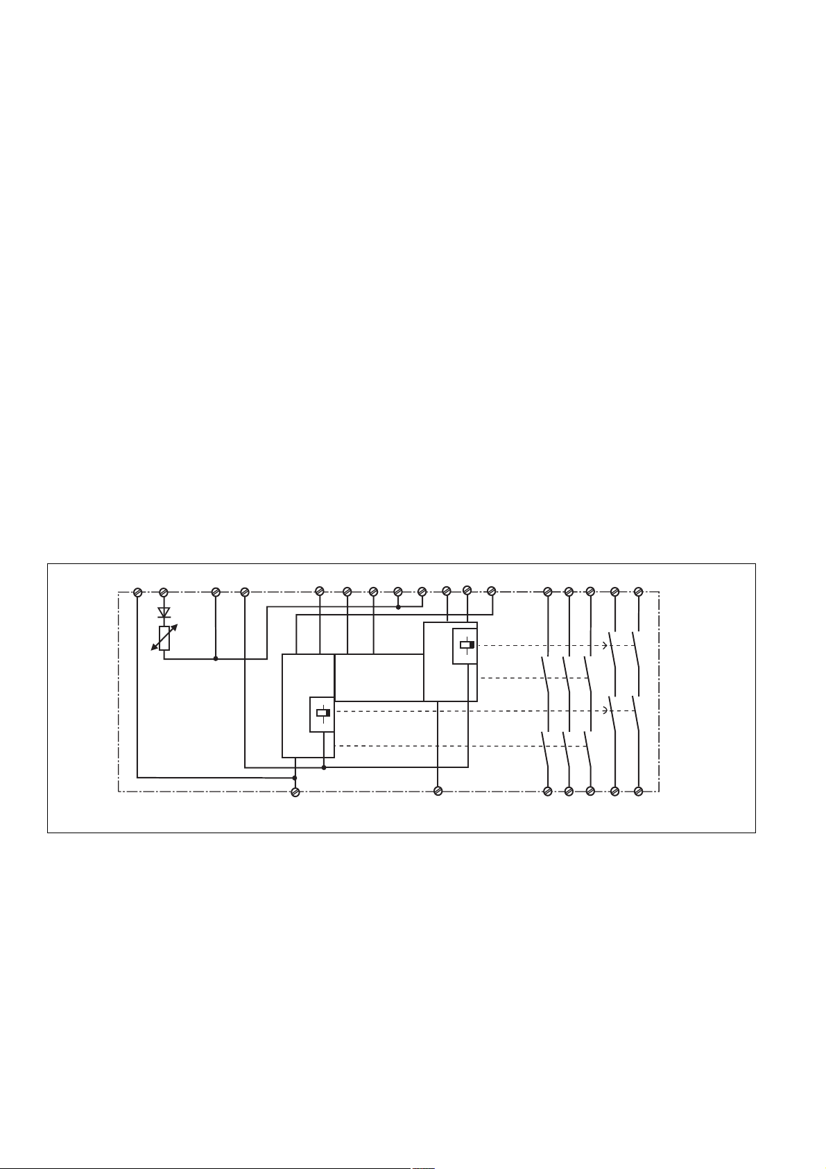
Funktionsbeschreibung
Das Schaltgerät PNOZ XV3P dient dem
sicherheitsgerichteten Unterbrechen eines
Sicherheitsstromkreises. Nach Anlegen der
Versorgungsspannung leuchtet die LED
"POWER". Das Gerät ist betriebsbereit, wenn
der Startkreis S13-S14 geschlossen ist oder
ein Startkontakt an S33-S34 geöffnet und
wieder geschlossen wurde. Die Statusanzeige
"START" leuchtet.
• Eingangskreis geschlossen (z. B. NOTAUS-Taster nicht betätigt):
Relais K1, K2, K3 und K4 gehen in
Wirkstellung und halten sich selbst. Die
Statusanzeigen für "CH.1", "CH.2" und
"CH.1(t), "CH.2(t)" leuchten. Die Sicherheitskontakte 13-14/23-24/33-34/47-48 und
57-58 sind geschlossen.
• Eingangskreis wird geöffnet (z. B. NOTAUS-Taster betätigt):
Relais K1 und K2 fallen in die Ruhestellung
zurück. Die Statusanzeige für "CH.1" und
"CH.2" erlischt. Die Sicherheitskontakte 1314, 23-24 und 33-34 werden redundant
geöffnet. Nach Ablauf der eingestellten
Verzögerungszeit fallen die Relais K3 und
K4 zurück. Die Sicherheitskonstakte 47-48
und 57-58 öffnen und die LED "CH.1(t)" und
"CH.2(t)" erlöschen.
Bevor das Gerät erneut gestartet werden
kann, muss die Verzögerungszeit abgelaufen
und alle Eingangskreise und Sicherheitskontakte müssen wieder geschlossen sein.
Verzögerungszeit unterbrechen:
Durch Betätigen eines Reset-Tasters (Y39Y40) wird die eingestellte Verzögerungszeit
unterbrochen und die Sicherheitskontakte 4748 und 57-58 sofort geöffnet.
Function Description
The relay PNOZ XV3P provides a safetyoriented interruption of a safety circuit. When
the operating voltage is supplied the LED
"POWER" is illuminated. The unit is ready
for operation, when the reset circuit S13-S14
is closed or a reset contact at S33-S34 was
opened and closed again. The status
indicator "START" illuminate.
• Input Circuit closed (e.g. the Emergency
Stop button is not pressed):
Relays K1, K2, K3 and K4 energise and
retain themselves. The status indicators
for "CH.1", "CH.2" and "CH.1(t)", CH.2(t)"
illuminate. The safety contacts (13-14/2324/33-34/47-48/57-58) are closed.
• Input Circuit is opened (e.g. Emergency
Stop is pressed)
Relays K1 and K2 de-energise. The status
indicators for "CH.1" and "CH.2" go out.
The safety contacts 13-14/23-24 and 3334 will be opened (redundant). Following
the delay-on de-energisation period, relays
K3 and K4 de-energise. The safety
contacts 47-48 and 57-58 opens and the
LED "CH.1(t)" and "CH.2(t)" extinguish.
The unit may only be reset once the delayon-de-energisation period has lapsed and all
input circuits and safety contacts are closed.
Interruption of Delay-on De-energisation:
By opening the contact Y39-Y40 i.e. pressing
a button connected the set delay-on deenergisation will be interrupted and the safety
contacts 47-48 and 57-58 will open
immediately.
Description du fonctionnement
Le relais PNOZ XV3P assure de façon sure,
l’ouverture d’un circuit de sécurité. A la mise
sous tension du relais (A1-A2), la LED
"POWER" s'allume. Le relais est activé si le
circuit de réarmement S13-S14 est fermé ou
si le contact de réarmement sur S33-S34 a
été ouvert puis refermé. La LED "START"
s'allume.
• Circuits d'entrée fermés (poussoir AU non
actionné) :
Les relais K1, K2, K3 et K4 passent en
position travail et s'auto-maintiennent. Les
LEDs "CH.1", " CH.2" et "CH.1(t)",
"CH.2(t)" s'allument. Les contacts de
sécurité (13-14/23-24/33-34/47-48/57-58)
sont fermés.
• Circuits d'entrée ouverts (poussoir AU
actionné) :
Les relais K1 et K2 retombent. Les LEDs
"CH.1" et "CH.2" s'éteingnent. Les
contacts de sécurité 13-14/23-24/33-34
s'ouvrent. Au bout de la temporisation
affichée, les relais K3 et K4 retombent. Les
contacts de sécurité 47-48/57-58 s'ouvrent
et les LEDs "CH.1(t)" et "CH.2(t)"
s'éteignent.
Avant un nouveau réarmement de l’appareil,
la temporisation à la retombée doit être
écoulée et tous les canaux d’entrée et
contacts de sortie doivent être à nouveau
fermés.
Arrêt de la temporisation
Un action sur un BP rellé au bornes Y39-Y40
(contact à ouverture) permet d'interrompre
prématurément la temporisation et d'ouvrir
instantanément les contacts de sortie 47-48
et 57-58.
S33
A1
A2
-
+
Y40
Y39
S34
CH2
S21
Fig. 1: Innenschaltbild/Internal Wiring Diagram/Schéma de principe
Betriebsarten:
• Einkanaliger Betrieb: Eingangsbeschaltung
nach VDE 0113-1 und EN 60204, keine
Redundanz im Eingangskreis, Erdschlüsse
im Tasterkreis werden erkannt.
• Zweikanaliger Betrieb: Redundanter Eingangskreis, Erdschlüsse im Tasterkreis
und Querschlüsse zwischen den Tasterkontakten werden erkannt.
• Automatischer Start: Gerät ist aktiv, sobald
Eingangskreis geschlossen ist.
• Manueller Start mit Überwachung: Gerät
ist nur aktiv, wenn vor dem Schließen des
Eingangskreises der Startkreis (S33-S34)
geöffnet wird und mind. 300 ms nach dem
Schließen des Eingangskreises der
Startkreis geschlossen wird.
• Kontaktvervielfachung und -verstärkung
durch Anschluss von externen Schützen
Operating Modes
• Single-channel operation: Input wiring
according to VDE 0113 and EN 60204, no
redundancy in the input circuit, earth faults
are detected in the emergency stop circuit.
• Two-channel operation: Redundancy in the
input circuit, earth faults in the Emergency
Stop circuit and shorts across the
emergency stop push button are also
detected.
• Automatic reset: Unit is active as soon as
the input circuit is closed.
• Manual reset with monitoring: The unit is
only active if, the reset circuit (S33-S34) is
opened before closing the safety input
circuit, and then the reset circuit is closed
at least 300 ms after closing the safety
input circuit.
• Increase in the number of available
contacts by connection of external
contactors/relays.
S14
Start
Unit
S13
- 2 -
S11
S22
S12
CH1
S31
S32
13 47
K1
K2
14 48
33
23
24
34
57
K3
K4
58
Modes de fonctionnement
• Commande par 1 canal : conforme aux
prescriptions de la EN 60204, pas de
redondance dans le circuit d’entrée, la
mise à la terre du circuit d’entrée est
détectée
• Commande par 2 canaux: circuit d’entrée
redondant, la mise à la terre et les courtscircuits entre les contacts sont détectés.
• Réarmement automatique : le relais est
activé dès la fermeture des canaux
d’entrée.
• Réarmement manuel auto-contrôlé: le
relais n'est réarmé que si le circuit de
réarmement (S33-S34) est ouvert avant la
fermeture du circuit d'entrée, puis refermé
au min. 300 ms après la fermeture du
circuit d'entrée.
• Augmentation du nombre de contacts ou
du pouvoir de coupure par l’utilisation de
contacteurs externes.
Page 3

Montage
Das Sicherheitsschaltgerät muss in einen
Schaltschrank mit einer Schutzart von mind.
IP54 eingebaut werden. Zur Befestigung auf
einer Normschiene dient ein Rastelement auf
der Rückseite des Geräts.
Sichern Sie das Gerät bei Montage auf einer
senkrechten Tragschiene (35 mm) durch ein
Halteelement wie z. B. Endhalter oder
Endwinkel.
Installation
The safety relay must be panel mounted
(min. IP54). There is a notch on the rear of
the unit for DIN-Rail attachment.
If the unit is installed on a vertical mounting
rail (35 mm), ensure it is secured using a
fixing bracket such as end bracket.
Montage
Le relais doit être monté en armoire ayant
unndice de protection mini IP54. Sa face
arrière ipermet un montage sur rail DIN.
Immobilisez l'appareil monté sur un rail DIN
vertical (35 mm) à l'aide d'un élément de
maintien comme par ex. un support ou une
équerre terminale.
Inbetriebnahme
Beachten Sie bei der Inbetriebnahme:
• Auslieferungszustand (Schraubklemmen):
Brücke zwischen S11-S12 (Eingangskreis
zweikanalig) und Y39-Y40.
• Vor die Ausgangskontakte eine
Sicherung (s. technische Daten)
schalten, um das Verschweißen der
Kontakte zu verhindern.
• Berechnung der max. Leitungslänge I
R
lmax
=
I
max
Rl / km
R
= max. Gesamtleitungswiderstand
lmax
(Eingangskreis)
Rl /km = Leitungswiderstand/km
• Da die Funktion Querschlusserkennung
nicht einfehlersicher ist, wird sie von Pilz
während der Endkontrolle geprüft. Eine
Überprüfung nach der Installation des
Geräts ist wie folgt möglich:
1. Gerät betriebsbereit (Ausgangskontakte
geschlossen)
2. Die Testklemmen S22-S32 zur
Querschlussprüfung kurzschließen.
3. Die Sicherung im Gerät muss auslösen
und die Ausgangskontakte öffnen.
Leitungslängen in der Größenordnung der
Maximallänge können das Auslösen der
Sicherung um bis zu 2 Minuten verzögern.
4. Sicherung wieder zurücksetzen: den
Kurzschluss entfernen und die Versorgungsspannung für ca. 1 Minute abschalten.
• Leitungsmaterial aus Kupferdraht mit einer
Temperaturbeständigkeit von 60/75 °C
verwenden.
• Angaben im Kapitel „Technische Daten“
unbedingt einhalten.
Ablauf:
• Versorgungsspannung an Klemmen A1
und A2 anlegen.
• Startkreis:
- Automatischer Start: S13-S14 brücken.
- Bitte beachten Sie: Der Start wird nach
Öffnen der Verbindung S13-S14 für
ca. 10 s gespeichert.
- Manueller Start mit Überwachung:
Taster an S33-S34 anschließen (S13S14 offen)
• Eingangskreis:
- Einkanalig: S21-S22 und S31-S32
brücken. Öffnerkontakt von Auslöseelement an S11 und S12 anschließen.
- Zweikanalig ohne Querschluss-
erkennung: S21-S22 brücken. Öffnerkontakt von Auslöseelement an
S11-S12 und S11-S32 anschließen.
- Zweikanalig mit Querschluss-
erkennung: S11-S12 brücken. Öffnerkontakt von Auslöseelement an
S21-S22 und S31-S32 anschließen.
• Reset Verzögerungszeit
Taster oder Brücke an Y39-Y40 anschließen
max
Operation
Please note for operation:
• Unit (screw terminals) delivered with a
bridge between S11-S12 (2-channel input
circuit) and Y39-Y40.
• To prevent a welding together of the
contacts, a fuse (see technical data)
must be connected before the output
contacts.
:
• Calculate the max. Cable runs I
R
lmax
=
I
max
• As the function for detecting shorts across
• Use copper wiring that will withstand
• Important details in the section "Technical
To operate:
• Connect the operating voltage to terminals
• Reset circuit:
• Input circuit:
• Reset delay-on-de-energisation
Rl / km
R
= max. Total cable resistance (Input
lmax
circuit)
Rl /km = Cable resistance/km
the inputs is not failsafe, it is tested by Pilz
during the final control check. However, a
test is possible after installing the unit and
it can be carried out as follows:
1. Unit ready for operation (output contacts
closed)
2. Short circuit the test (connection)
terminals S22-S32 for detecting shorts
across the inputs.
3. The unit‘s fuse must be triggered and
the output contacts must open. Cable
lengths in the scale of the maximum length
can delay the fuse triggering for up to 2
minutes.
4. Reset the fuse:remove the short circuit
and switch off the operating voltage for
approx. 1 minute.
60/75 °C
Data“ should be noted and adhered to.
A1 and A2
- Automatic reset: Bridge S13-S14
- Please note: After opening the
connection S13-S14, the start will be
stored for ca. 10 s.
- Manual reset with monitoring: Connect
button to S33-S34 (S13-S14 open).
- Single-channel: Bridge S21-S22 and
S31-S32. Connect N/C contact from
safety switch (e.g. Emergency-Stop) to
S12 and S11.
- Dual-channel, without short circuit
detection: Link S21-S22. Connect N/C
contact from safety switch
(e.g. emergency stop) to S11-S12 and
S11-S32
- Dual-channel, with short circuit
detection: Bridge S11-S12. Connect N/C
contact from safety switch
(e.g. emergency-stop) to S21-S22 and
S31-S32.
Connect a button to Y39-Y40 or link Y39Y40
max
Mise en oeuvre
Remarques préliminaires :
• Pontages présents à la livraison (bornier à
vis): S11-S12 (commande par 2 canaux) et
Y39-Y40.
• Protection de contacts de sortie par des
fusibles (voir caractéristiques
techniques) normaux pour éviter leur.
• Calculer les longueurs de câblage max:
:
• La fonction de détection de court-circuit
• Utiliser uniquement des fils de cablâge en
• Respecter les données indiquées dans le
Mise en oeuvre :
• Tension d’alimentation: amener la tension
• Circuit de réarmement:
• Circuits d’entrée:
• Reset de la temporisation
R
lmax
=
I
max
Rl / km
R
= résistivité de câblage totale max.
lmax
(Circuits d’entrée)
Rl /km = résistivité de câblage/km
est testé par Pilz lors du contrôle final. Un
test sur site est possible de la façon
suivante :
1. Appareil en fonction (contacts de sortie
fermés)
2. Court-circuiter les bornes de
raccordement nécessaires au test S22-S32
3. Le fusible interne du relais doit
déclencher et les contacts de sortie
doivent s‘ouvrir. Le temps de réponse du
fuisible peut aller jusqu‘à 2 min. si les
longueurs de câblage sont proches des
valeurs maximales.
4. Réarmement du fusible : enlever le
court-circuit et couper l‘alimentation du
relais pendant au moins 1 min.
cuivre 60/75 °C.
chap. „Caractéristiques techniques“.
d’alimentation sur A1 et A2
- réarmement automatique: pontage des
bornes S13-S14
- Veuillez noter : le réarmement est
mémorisé env. 10 sec. après l’ouverture
du circuit S13-S14.
- réarmement manuel auto-côntrolé:
câblage d'un poussoir sur S33-S34
(S13-S14 ouvert).
- Commande par 1 canal : câblage du
contact à ouverture entre S11-S12,
pontage entre S21-S22 et S31-S32
- Commande par 2 canaux sans détection
des courts-circuits: câblage des contacts
à ouverture entre S11-S12, S11-S32,
pontage entre S21-S22
- Commande par 2 canaux
avec détection
des courts-circuits: câblage des contacts
à ouverture entre S21-S22 et S31-S32,
pontage entre S11-S12
Poussoir ou pont sur les bornes Y39-Y40
- 3 -
Page 4
•
S12
S14
S13
S11
S21
S32
S22
S1
S2
S31
Y39
Y40
Rückführkreis:
Externe Schütze in Reihe zu Startkreis
S13-S14 bzw. S33-S34 anschließen.
Die Sicherheitskontakte sind aktiviert (geschlossen). Die Statusanzeige für "CH.1",
"CH. 2", "CH.1(t)" und "CH.2(t)" leuchten.
Das Gerät ist betriebsbereit.
Wird der Eingangskreis geöffnet, öffnen die
Sicherheitskontakte 13-14/23-24/33-34 und
die Statusanzeigen "CH.1" und "CH.2"
erlöschen. Nach Ablauf der Verzögerungszeit
öffnen die Sicherheitskontakte 47-48/57-58
und die Statusanzeigen "CH.1(t)" und
"CH.2(t)" erlöschen.
Wieder aktivieren
• Eingangskreis schließen.
• Bei manuellem Start mit Überwachung
Taster zwischen S33 und S34 betätigen.
Die Statusanzeigen leuchten wieder, die
Sicherheitskontakte sind geschlossen.
•
Feedback control loop:
Connect external relays/contactors in
series to reset circuit S13-S14 or S33-S34
The safety contacts are activated (closed).
The status indicators "CH.1","CH.2", "CH.1(t)
and "CH.2(t)" are illuminated. The unit is
ready for operation. If the input circuit is
opened, the safety contacts 13-14/23-24/3334 open and the status indicators "CH.1" and
"CH.2" extinguish. After the delay-on-deenergisation period the saftey contacts 4748/57-58 open and the status indicators
"CH.1(t)2 and "CH.2(t)" extinguish.
Reactivation
• Close the input circuit.
• For manual reset with monitoring, press
the button and release between S33-S34.
The status indicators illuminate once more,
the safety contacts are closed.
• Boucle de retour:
câbler les contacts des contacteurs
externes en série dans le circuit de
réarmement S13-S14 ou S33-S34
Les contacts de sécurité se ferment. Les
LEDs "CH.1", "CH.2", "CH.1(t)" et "CH.2(t)"
sont allumées. L’appareil est prêt à
fonctionner.
Si le circuit d’entrée est ouvert, les contacts
de sécurité 13-14/23-24/33-34 retombent et
les LEDs "CH.1" et "CH.2" s'éteignent. À la
fin de la temporisation, les contacts de
sécurité 47-48/57-58 retombent et les LEDs
"CH.1(t)" et "CH.2(t)" s’éteignent.
Remise en route :
• fermer le circuit d’entrée
• en cas de surveillance du circuit de
réarmement, appuyer le poussoir de
validation S33-S34.
Les LEDs sont à nouveau allumées. Les
contacts de sécurité sont fermés.
Anwendung
In Fig. 2 ... Fig. 11 sind Anschlussbeispiele
für NOT-AUS-Beschaltung mit automatischem und überwachtem Start, Schutztürsteuerungen sowie Kontaktvervielfachung
durch externe Schütze dargestellt.
Bitte beachten Sie:
• Fig. 2 und 7: keine Verbindung S33-S34
Beachten Sie: Das Gerät startet bei
Spannungsausfall und -wiederkehr
automatisch. Verhindern Sie einen
unerwarteten Wiederanlauf durch externe
Schaltungsmaßnahmen.
• Fig. 3, 4, 5, 6, 8:
keine Verbindung S13-S14
• Fig. 7: Automatischer Start bei Schutztürsteuerung: Das Gerät ist bei geöffneter
Schutztür über den Startkreis S13-S14
startbereit. Nach Schließen der Eingangskreise S21-S22 und S31-S32 werden die
Sicherheitskontakte geschlossen.
S11 S31
S1
S21
S13
Y39
Application
In Fig. 2 ... Fig. 11 are connection examples
for Emergency Stop wiring with automatic
and monitored reset. Safety gate controls as
well as contact expansion via external
contactors.
• Fig. 2 and 7: S33-S34 not connected
Please note: the device starts
automatically after loss of power. You
should prevent an unintended start-up by
using external circuitry measures.
• Fig 3, 4, 5, 6, 8: S13-S14 not connected
• Fig. 7: Automatic reset with safety gate
control: with the safety gate open the unit
is ready for operation via reset circuit S13S14. After closing the safety input circuit
S21-S22 and S31-S32 the safety contacts
will close.
S11 S31
S1
S21
S3
S33
Y39
Utilisation
Les figures 2 à 11 représentent les différents
câblages possibles du PNOZ XV2 à savoir :
poussoir AU avec réarmement automatique
ou auto-côntrolé, interrupteurs de position et
augmentation du nombre des contacts de
sécurité par contacteurs externes.
• Fig. 2 et 7: pas de câblage sur S33-S34
L’appareil se réarme automatiquement
après une coupure et une remise sous
tension. Evitez tout risque de redémarrage
par un câblage externe approprié.
• Fig. 3, 4, 5, 6, 8:
pas de câblage sur S13-S14
• Fig. 7: Réarmement automatique en cas
de surveillance protecteur: lorsque le
protecteur est ouvert, le circuit S13-S14 se
ferme et le relais est prêt à fonctionner.
Dès la fermeture des canaux d'entrée S21S22 et S31-S32, les contacts de sortie du
relais se ferment.
S21 S11
S31
S1
S3
S33
Y39
S32
S12
S22
S14
Y40
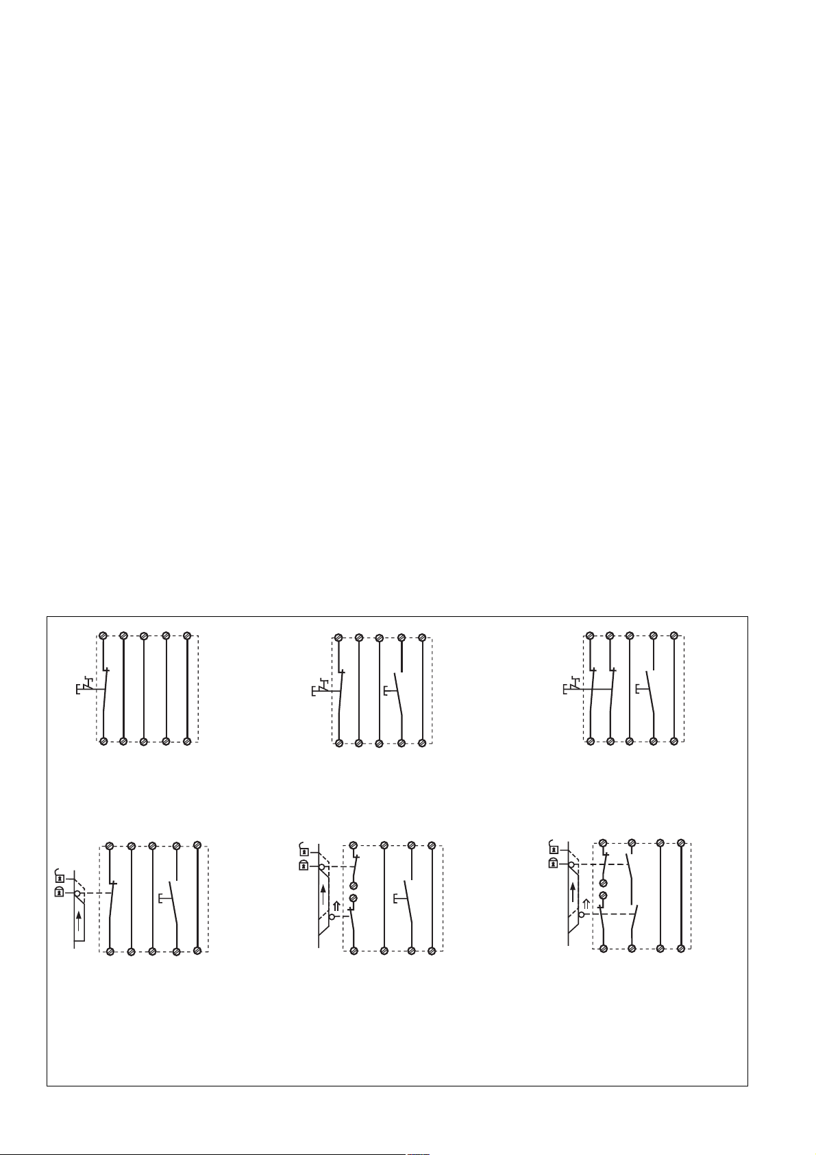
Fig. 2: Eingangskreis einkanalig, automat.
Start/Single-channel input circuit, automatic
reset/Commande par 1 canal, validation
automatique
S11
S12
S1
S21
S22
S31
S32
S3
S33
S34
Y39
Y40
Fig. 5: Schutztürsteuerung einkanalig,
überwachter Start/Single-channel safety gate
control, monitored reset/Surveillance de
protecteur, commande par 1 canal,
surveillance du poussoir de validation
S32
S12
S22
S34
Y40
Fig. 3: Eingangskreis einkanalig, überwachter Start/Single-channel input circuit,
monitored reset/Commande par 1 canal,
surveillance du poussoir de validation
Y39
S33
S11
S21
S1
S22
S3
S31
S2
S32
S12
S34
Y40
Fig. 6: Schutztürsteuerung zweikanalig,
überwachter Start/Two-channel safety gate
control, monitored reset/Surveillance de
protecteur, commande par 2 canaux,
surveillance du poussoir de validation
- 4 -
S12
S22
S32
S34
Y40
Fig. 4: Eingangskreis zweikanalig, überwachter Start/Two-channel input circuit, monitored
reset/Commande par 2 canaux, surveillance
du poussoir de validation
Fig. 7: Schutztürsteuerung zweikanalig,
automatischer Start, Gleichzeitigkeit S1 und
S2: max. 3 s/Two channel safety gate
control, automatic reset, simultaneity S1 and
S2: max. 3 s/Surveillance de protecteur,
commande par 2 canaux, validation
automatique, temps de synchronisme S1 et
S2 : max. 3 s
Page 5
BWS
S11
24 V DC
S3
S33S21S31
Y39
1L1
K7
K8
S13
K5
K6
S14
13
47
S12 S22 S34S32
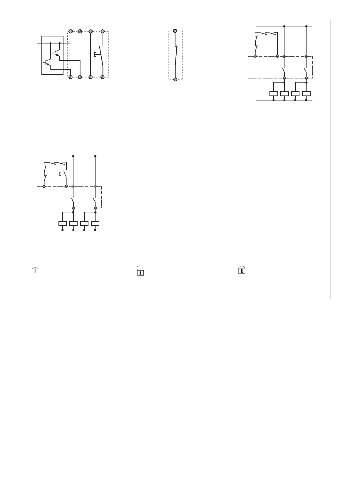
Fig. 8: Lichtschrankensteuerung, zweikanalig, Querschlusserkennung durch BWS,
überwachter Start/Dual-channel light curtain
control, short circuit detection via ESPE,
monitored reset/Commande par 2 canaux
par barrage immatériel ,surveillance du
poussoir de validation
1L1
K7
K8
S34
1L2
K5
K6
S3
13
S33
14
K5
K6
47
48
K8
K7
Fig. 11: wie Fig. 10 mit überwachtem Start/
connection for contactors/relays and
monitored reset/comme Fig. 10 avec
surveillance du poussoir de validation
Y40
Fig. 9: Öffnerkontakt für Reset der
Verzögerungszeit/N/C contact for reseting
the Delay-on De-energisation/Contact à
ouverture pour mise à 0 de la temporisation
48
K8
K7
1L2
14
K5
K6
Fig. 10: Anschlussbeispiel für externe
Schütze, einkanalig, automatischer Start/
Connection example for external contactors/
relays, single-channel, automatic reset/
Branchement contacteurs externes,
commande par 1 canal, validation
automatique
betätigtes Element/Switch
activated/élément actionné
Tür nicht geschlossen/Gate open/
porte ouverte
Tür geschlossen/Gate closed/
porte fermée
S1/S2: NOT-AUS- bzw. Schutztürschalter/Emergency Stop Button, Safety Gate Limit Switch/Poussoir AU, détecteurs de position
S3: Starttaster/Reset button/Poussoir de réarmement
Fehler - Störungen
• Erdschluss
Die Versorgungsspannung bricht zusammen und die Sicherheitskontakte werden
über eine elektronische Sicherung
geöffnet. Nach Wegfall der Störungsursache und Abschalten der Versorgungsspannung für ca. 1 Minute ist das Gerät
wieder betriebsbereit.
• Fehlfunktionen der Kontakte: Bei verschweißten Kontakten ist nach Öffnen des
Eingangskreises keine neue Aktivierung
möglich.
• LED "POWER" leuchtet nicht: Kurzschluss
oder Versorgungsspannung fehlt.
• Abbruch der Verzögerungszeit
Im Fehlerfall können die rückfallverzögerten Kontakte vor Ablauf der
Verzögerungszeit öffnen.
Faults
• Earth fault
Supply voltage fails and the safety
contacts are opened via an electronic fuse.
Once the cause of the fault has been
removed and operating voltage is switched
off, the unit will be ready for operation after
approximately 1 minute.
• Contact failure: In the case of welded
contacts, no further activation is possible
following an opening of the input circuit.
• LED "POWER" is not illuminated if shortcircuit or the supply voltage is lost.
• Delay time aborted
In the case of an error, the delay-on deenergisation contacts may open before the
delay time has elapsed.
Erreurs - Défaillances
• Défaut de masse
La tension d’alimentation chute et les
contacts de sécurité sont ouverts par un
fusible électronique. Une fois la cause du
défaut éliminée et la tension d’alimentation
coupée, l’appareil est à nouveau prêt à
fonctionner après environ 1 minute.
• Défaut de fonctionnement des contacts de
sortie: en cas de soudage d’un contact lors
de l’ouverture du circuit d’entrée, un
nouvel réarmement est impossible.
• LED "POWER" éteinte: tension
d'alimentation non présente ou courtcircuit interne.
• Temporisation interrompue
En cas de défaut, les contacts temporisés
à la retombée peuvent s'ouvrir avant
l'écoulement de la temporisation.
- 5 -
Page 6

Technische Daten/Technical Data/Caractéristiques techniques
Versorgungsspannung UB/Operating Voltage/Tension d’alimentation 24 V DC
Spannungstoleranz/Voltage Tolerance/Plage de la tension d’alimentation -15 ... +10 %
Leistungsaufnahme bei UB/Power Consumption/Consommation 4,5 W
Restwelligkeit/Residual Ripple/Ondulation résiduelle DC: 160 %
Spannung und Strom an/Voltage, Current at //Tension et courant du
Eingangskreis/Input circuit/circuit d’entrée 24 V DC, 35,0 mA
Startkreis/reset circuit/circuit de réarmement 24 V DC, 50,0 mA
Rückführkreis/feedback loop/boucle de retour 24 V DC, 3,5 mA
Ausgangskontakte/Output Contacts/Contacts de sortie
Unverzögert/Instantaneous/Instantés 3 Sicherheitskontakte/Safety contacts/
Verzögert/Delayed/Temporisés à retombée 2 Sicherheitskontakte/Safety contacts/
Kategorie nach EN 954-1/Category to EN 954-1/Catégorie d'après EN 954-1
Unverzögert/Instantaneous/Instantés 4
Verzögert <30s / Delayed <30s / Temporisés à retombée <30s 3
Verzögert ≥30s / Delayed ≥30s / Temporisés à retombée ≥30s 1
Gebrauchskategorie nach/Utilization category to/Catégorie d’utilisation d'après
EN 60947-4-1
AC1: 240 V I
DC 1: 24 V I
EN 60947-5-1
AC 15: 230 V I
DC13 (6 Schaltspiele/Min, 6 cycles/min, 6 manoeuvres/min): 24 V I
Kontaktmaterial/Contact material/Matériau contact AgSnO2+ 0,2 µm Au
Kontaktabsicherung extern nach/External Contact Fuse Protection/Protection des contacts
EN 60 947-5-1 (IK = 1 kA)
Schmelzsicherung/Blow-out fuse/Fusibles 10 A flink/quick acting/rapide oder /or/ou
Sicherungsautomat/Safety cut-out/Dijoncteur 24 V AC/DC: 6 A Charakteristik /
Max. Gesamleitungswiderstand R
(input circuit)/Résistivité de câblage totale max. R
einkanalig DC/Single-channel DC/Commande par 1 canal DC 100 Ohm
(Eingangskreis) /Max. total cable resistance R
lmax
(Circuits d’entrée)
lmax
lmax
zweikanalig mit Querschlusserkennung/Dual-channel with detection of shorts across
contacts/Commande par 2 canaux avec détection des court-circuits 10 Ohm
zweikanalig ohne Querschlusserkennung /Dual-channel without detection of shorts across
contacts/Commande par 2 canaux sans détection des court-circuits 100 Ohm
Einschaltverzögerung/Switch-on delay/Temps d’enclenchement
Automatischer Start/Automatic reset/Réarmement automatique typ. 350 ms, max. 650 ms
Automatischer Start nach Netz-Ein/Automatic reset after Power-ON/ Réarmement
automatique après mise sous tension typ. 385 ms, max. 700 ms
Überwachter Start/Monitored manual reset/Réarmement manuel auto-contrôlé typ. 35 ms, max. 70 ms
Rückfallverzögerung /Delay-on De-Energisation /Temps de retombée
bei NOT-AUS/at E-STOP/en cas d'arrêt d'urgence typ. 15 ms, max. 30 ms
bei Netzausfall/with power failure/en cas de coupure d'alimentation typ. 85 ms, max. 200 ms
Verzögerungszeit/Delay-on De-Energisation/Temps de retombée t
einstellbar/adjustable/réglable 0,1-3 s: 0,1/0,2/0,3/0,4/0,5/0,6/0,7/0,8/1/
v
fest/fixed/fixe 0,5 s, 3,0 s, 10,0 s
Wiederholgenauigkeit/Repetition accuracy/Précision de reproductibilité 2 %
Zeitgenauigkeit/Time accuracy/Précision du temps -15% / +15% +50 ms
Wiederbereitschaftszeit bei max. Schaltfrequenz 1/s/recovery time at max. switching
frequency 1/s/temps de remise en service en cas de fréquence de commutation max. 1/s
nach NOT-AUS/after E-STOP/après l'arrêt d'urgence 50 ms + tv
nach Netzausfall/after power failure/après une coupure d'alimentation 250 ms
Wartezeit bei überwachtem Start/Waiting period on monitored reset/Temps d’attente en
cas d’un démarrage surveillé 300 ms
Gleichzeitigkeit Kanal 1 und 2/Simultaneity channel 1 and 2/Désynchronisme canal 1 et 2 ∞
Min. Startimpulsdauer bei überwachtem Start/Min. start pulse duration with a monitored
reset/Durée minimale de l'impulsion pour un réarmement auto-contrôlé 30 ms
Überbrückung bei Spannungseinbrüchen/Max. supply interruption before
de-energisation/Tenue aux micro-coupures 20 ms
EMV/EMC/CEM
Schwingungen nach/Vibration to/Vibrations d'après EN 60068-2-6
Klimabeanspruchung/Climate Suitability/Conditions climatiques EN 60068-2-78
Luft- und Kriechstrecken nach/Airgap Creepage to/Cheminement et claquage
d'après
EN 60947-1
Verschmutzungsgrad/Pollution degree/Niveau d'encrassement 2
Bemessungsisolationsspannung/Rated insulation voltage/Tension assignée d’isolement 250 V
Bemessungsstoßspannungsfestigkeit/Rated impulse withstand voltage/Tension assignée
de tenue aux chocs 4 kV
Contacts de securitè
Contacts de securitè
: 0,01 A, I
min
: 0,01 A, I
min
: 5,0 A
max
: 7,0 A
max
: 8,0 A, P
max
: 8,0 A, P
max
: 2000 VA
max
: 200 W
max
6 A träge/slow acting/normeaux
Characteristic/Caractéristiques B/C
1,5/2/3 s
0-30 s: 0/0,5/1/2/4/6/8/10/15/20/25/30 s
0-300 s: 0/5/10/20/40/60/80/100/150/200/
250/300 s
EN 60947-5-1, EN 61000-6-2
Frequenz/Frequency/Fréquences:10-55 Hz
Amplitude/Amplitude/Amplitude: 0,35 mm
- 6 -
Page 7

Betriebstemperatur/Operating Temperature/Température d’utilisation -10 - 55 °C
Lagertemperatur/Storage Temperature/Température de stockage -40 - 85 °C
Schutzart/Protection/Indice de protection
Einbauraum (z. B. Schaltschrank)/Mounting (eg. panel)/Lieu d'implantation (ex. armoire) IP54
Gehäuse/Housing/Boîtier IP40
Klemmenbereich/Terminals/Bornes IP20
Gehäusematerial/Housing material/Matériau du boîtier
Gehäuse/Housing/Boîtier PPO UL 94 V0
Front/Front panel/Face avant ABS UL 94 V0
Max. Querschnitt des Außenleiters (Schraubklemmen)/Max. cable cross section (screw
terminals)/ Capacité de raccordement (borniers à vis)
1 Leiter, flexibel/1 core, flexible/1 conducteur souple 0,25 - 2,5 mm2/24-12 AWG
2 Leiter gleichen Querschnitts, flexibel mit Aderendhülse, ohne Kunststoffhülse/
2 core, same cross section flexible with crimp connectors, without insulating sleeve/
2 conducteurs de même diamètre souple avec embout, sans chapeau plastique 0,25 - 1 mm2/24-16 AWG
ohne Aderendhülse oder mit TWIN-Aderendhülse/without crimp connectors or with TWIN
crimp connectors/souple sans embout ou avec embout TWIN 0,2 - 1,5 mm
2
/24-16 AWG
Max. Querschnitt des Außenleiters (Käfigzugfederklemmen)/Max. cable cross section (cage
clamp terminals)/Capacité de raccordement (borniers à ressort)
flexibel ohne Aderendhülse/flexible without crimp connectors/souple sans embout 0,2 - 1,5 mm2/24-16 AWG
Gehäuse mit Käfigzugfederklemmen/Housing with cage clamp terminals/
Boîtier avec borniers à ressort/
Abisolierlänge/Stripping length/Longueur de dénudage 8 mm
Klemmstellen pro Anschluss/Termination points per connection/bornes par raccordement 2
Anzugsdrehmoment Schrauben (auf Anschlussklemmen)/Torque setting for connection terminal
screws/Couple de serrage (bornier) 0,50 Nm
Abmessungen (Schraubklemmen) H x B x T/Dimensions H x W x D (screw terminals)/
Dimensions (borniers à vis) H x P x L 94 x 45 x 121 mm
Abmessungen (Käfigzugfederklemmen) H x B x T/Dimensions (cage clamp terminals)
H x W x D/ Dimensions (borniers à ressort) H x L x P 101 x 45 x 121 mm
Einbaulage/Fitting Position/Position de travail beliebig; any; indifférente
Gewicht/Weight/Poids 370 g
Es gelten die 08/02 aktuellen Ausgaben der
Normen.
The version of the standards current at 08/02
shall apply.
Se référer à la version des normes en vigeur
au 08/02.
Konventioneller thermischer Strom bei gleichzeitiger Belastung mehrerer Kontakte/Conventional thermal
current while loading several contacts/Courant thermique conventionnel en cas de charge sur plusieurs
contacts (AC1, DC1)
Anzahl der Kontakte/number of contacts/nombre des contacts 5 4321
Ith (A) pro Kontakt bei Versorgungsspannung DC/per contact
with operating voltage DC/par contact pour tension d’alimentation DC 4,3 4,8 5,5 6,8 8,0
Um ein Versagen der Geräte zu verhindern,
an allen Ausgangskontakten für eine ausreichende Funkenlöschung sorgen. Bei
kapazitiven Lasten sind eventuell auftretende
Stromspitzen zu beachten. Bei DC-Schützen
Freilaufdioden zur Funkenlöschung einset-
To prevent failure of the unit, all output
contacts should be fused adequately. With
capacative loads, possible current peaks are
to be avoided. With DC contactors/relays
use suitable spark suppression to ensure
extended life of the contactors/relays.
Prévoir un dispositif d’extinction d’arc sur les
contacts de sortie pour éviter un éventuel
disfonctionnement du relais.
Tenir compte des pointes d’intensité en cas
de charge capacitive. Equiper les
contacteurs DC de diodes de roue libre .
zen, um die Lebendauer der Schütze zu
erhöhen.
Lebensdauer der Ausgangsrelais/Service Life of Output relays/Durée de vie des relais de sortie
10
AC15: 230 V
DC1: 24 V
DC13: 24 V
1
Courant coupé (A)
Nennbetriebstrom (A)
Nominal operating current (A)
0.1
10 100 1000 10000
Schaltspielzahl x 10
Cycles x 10
Nombre de manvres x 10
AC1: 230 V
3
3
3
- 7 -
Page 8

Steckbare Klemmen abziehen
Schraubendreher in Gehäuseaussparung
hinter der Klemme ansetzen und Klemme
heraushebeln.
Klemmen nicht an den Kabeln abziehen!
Remove plug-in terminals
Insert screwdriver into the cut-out of the
housing behind the terminal and lever the
terminal.
Do not remove the terminals by pulling the
cables!
Démonter les borniers
débrochables
Placer un tournevis derrière les bornes et
sortir le bornier.
Ne pas retirer les borniers en tirant sur les
câbles !
Abziehen der Klemmen am Beispiel einer
Schraubklemme
How to remove the terminals using a screw
terminal as an example
Abmessungen in mm (")/Dimensions in mm (")/Dimensions en mm (")
Gehäuse mit steckbaren Schraubklemmen/
Housing with plug-in screw terminals/
Boîtier avec borniers débrochables à vis
121 (4.76")
75 (2.95")
87 (3.42")
94 (3.70")
45
(1.77")
Gehäuse mit steckbaren Käfigzugfederklemmen/
Housing with plug-in cage clamp terminals/
Boîtier avec borniers débrochables à ressort/
75 (2.95")
87 (3.42")
101 (3.98")
Démontage d’un bornier à vis
121 (4.76")
45
(1.77")
A
Pilz Ges.m.b.H., ✆ 01 7986263-0, Fax: 01 7986264
Fax: 09 3217571
DK
Pilz Skandinavien K/S, ✆ 74436332, Fax: 74436342
✆
03 88104000, Fax: 03 88108000
Fax: 01536 460866
J
Pilz Japan Co., Ltd., ✆ 045 471-2281, Fax: 045 471-2283
NL
Pilz Nederland, ✆ 0347 320477, Fax: 0347 320485
✆
229407594, Fax: 229407595
Fax: 031 8159542
✆
0224 2360180, Fax: 0224 2360184
D
Pilz GmbH & Co. KG, Sichere Automation, Felix-Wankel-Straße 2, 73760 Ostfildern, Deutschland, ✆ +49 711 3409-0, Fax: +49 711 3409-133,
E-Mail: pilz.gmbh@pilz.de
BR
Pilz do Brasil, ✆ 11 4337-1241, Fax: 11 4337-1242
FIN
I
Pilz ltalia Srl, ✆ 031 789511, Fax: 031 789555
PRC
SE
Pilz Skandinavien K/S, ✆ 0300 13990, Fax: 0300 30740
Pilz Skandinavien K/S, ✆ 09 27093700, Fax: 09 27093709
Pilz China Representative Office, ✆ 021 62494658, Fax: 021 62491300
USA
Pilz Automation Safety L.P., ✆ 734 354-0272, Fax: 734 354-3355
AUS
Pilz Australia, ✆ 03 95446300, Fax: 03 95446311
CH
E
Pilz lndustrieelektronik S.L., ✆ 938497433, Fax: 938497544
Pilz lndustrieelektronik GmbH, ✆ 062 88979-30, Fax: 062 88979-40
GB
IRL
MEX
NZ
Pilz New Zealand, ✆ 09- 6345-350, Fax: 09-6345-352
Pilz Ireland Industrial Automation, ✆ 021 4346535, Fax: 021 4804994
Pilz de Mexico, S. de R.L. de C.V., ✆ 55 5572 1300, Fax: 55 5572 4194
TR
Pilz Elektronik Güvenlik Ürünleri ve Hizmetleri Tic. Ltd. ¸Sti.,
- 8 -
B L
Pilz Automation Technology, ✆ 01536 460766,
ROK
www
Pilz Belgium, ✆ 09 3217570,
F
Pilz France Electronic,
P
Pilz Industrieelektronik S.L.,
Pilz Korea, ✆ 031 8159541,
www.pilz.com
20 122-04-2007-02 Printed in Germany
Page 9

20 122-04
PNOZ XV3P
4 E Instrucciones de uso
4 I Istruzioni per l`uso
4 NL Gebruiksaanwijzing
Prescripciones de seguridad
• El dispositivo debe instalado y puesto en
funcionamiento exclusivamente por
personas que estén familiarizadas tanto
con estas instrucciones de uso como con
las prescripciones vigentes relativas a la
seguridad en el trabajo y a la prevención de
accidentes. Observar las prescripciones
VDE y las prescripciones locales,
especialmente en lo que se refiere a las
medidas de protección.
• Durante el transporte, el almacenaje y el
funcionamiento, atenerse a la norma
EN 60068-2-6 (ver datos técnicos).
• La garantía se pierde en caso de que se
abra la carcasa o se lleven a cabo
remodelaciones por cuenta propia.
• Montar el dispositivo dentro de un armario
de distribución; de lo contrario el polvo y la
suciedad pueden afectar el funcionamiento.
• Cuidar de que haya un conexionado de seguridad suficiente en todos los contactos de
salida con cargas capacitivas e inductivas.
Campo de aplicación adecuado
El dispositivo de seguridad cumple los
requisitos de las normas EN 60947-5-1,
EN 60204-1 y VDE 0113-1 y puede utilizarse
en aplicaciones con
• pulsadores de parada de emergencia
• puertas protectoras
Norme di sicurezza
• Il dispositivo può venire installato e messo in
funzione solo da persone che conoscono
bene le presenti istruzioni per l’uso e le disposizioni vigenti riguardo alla sicurezza di
lavoro e all’antinfortunistica. Osservare le disposizioni della VDE (Associazione tedesca
degli Ingegneri) nonché le norme locali,
soprattutto per quanto riguarda le misure
preventive di protezione.
• Per il trasporto, l’immagazzinamento e
l’esercizio attenersi alle condizioni a norma
EN 60068-2-6 (v. Dati tecnici).
• Se viene aperta la custodia oppure se vengono apportate delle modifiche in proprio
decade qualsiasi diritto di garanzia.
• Montare il dispositivo in un armadio elettrico;
altrimenti la polvere e l’umidità possono pregiudicare le funzioni.
• Preoccuparsi che tutti i contatti di uscita sui
carichi capacitivi e induttivi siano dotati di un
cablaggio protettivo sufficiente.
Uso previsto
Il modulo di sicurezza risponde ai requisiti
secondo EN 60947-5-1, EN 60204-1 e
VDE 0113-1 e può essere utilizzato in
applicazioni con
• pulsanti di arresto d'emergenza
• ripari mobili
Veiligheidsvoorschriften
• Het apparaat mag uitsluitend worden geïnstalleerd en in bedrijf genomen door personen die vertrouwd zijn met deze gebruiksaanwijzing en met de geldende
voorschriften op het gebied van
arbeidsveiligheid en ongevallenpreventie.
Neemt u de van toepassing zijnde
Europese richtlijnen en de plaatselijke voorschriften in acht, in het bijzonder m.b.t.
veiligheidsregels.
• Neem bij transport, opslag en in bedrijf de
richtlijnen volgens EN 60068-2-6 in acht
(zie technische gegevens).
• Het openen van de behuizing of het eigenmachtig aanpassen heeft verlies van de
garantie tot gevolg.
• Monteer het apparaat in een schakelkast.
Stof en vocht kunnen anders de werking
nadelig beïnvloeden.
• Zorg bij alle uitgangscontacten bij
capacitieve en inductieve belastingen voor
voldoende beschermbedrading.
Toegelaten applicaties
Het veiligheidsrelais voldoet aan de eisen van
EN 60947-5-1, EN 60204-1 en
VDE 0113-1 en mag worden gebruikt in
toepassingen met
• noodstopknoppen
• hekken
Descripción del dispositivo
El dispositivo de Parada de emergencia se
encuentra montado dentro de una carcasa
P-99. Existe un modelo para el
funcionamiento con 24 V tensión continua.
Características:
• Salidas de relé, sin retardo:
3 contactos de seguridad (S), con guía forzada
• Salidas de relé, con retardo a la desconexión: 2 contactos de seguridad (norm.
abierto), con guía forzada y retardo a la
desconexión ajustable o fijo (según el dispositivo)
• Indicadores de estado para tensión de alimentación, estado de conexión de todos
los relés de salida y circuito de rearme
• Conexión para pulsador de Parada de
emergencia, interruptor final de seguridad
o interruptor de puerta protectora y para
pulsador de rearme
• Conexión redundante de salida
• Modo monocanal o bicanal
• Circuito de realimentación para la supervisión de contactores externos
El dispositivo cumple los requerimientos de
seguridad siguientes:
• La instalación de seguridad permanece activa también en los siguientes casos:
- Corte de la tensión
- Fallo de un elemento constructivo
- Defecto de bobina
- Rotura de línea
- Contacto a tierra
• Comprobación con cada ciclo de conexión/
desconexión si los relés de salida del dispositivo de seguridad abren y cierran correctamente.
Descrizione dell’apparecchio
Il relè per arresto di emergenza è inserito in
un alloggiamento P-99. È disponibile una
versione per il funzionamento con corrente
continua 24V.
Caratteristiche:
• Uscite relè, senza ritardo:
3 contatti di sicurezza (S), a guida positiva
• Uscite relè, con ritardo tempo di scatto:
2 contatti di sicurezza (S), a guida positiva
con ritardo del tempo di scatto registrabile
regolabile o fisso (in base all’unità)
• LED per tensione di alimentazione, LED per
visualizzazione dei relè di uscita e del
circuito di Start
• Collegamento per pulsante di arresto di
emergenza interruttore di fine corsa tasti
o interruttore porta di protezione e per
tasti di Start.
• Circuito d’uscita ridondante
• Azionamento ad uno o due canali
• Circuito di retroazione per il controllo di
relè esterni
Il modulo risponde ai seguenti requisiti di
sicurezza:
• La funzione di sicurezza rimane attiva
anche nei casi seguenti:
- caduta di tensione
- guasto di un componente
- difetto della bobina
- rottura di cavi
- dispersione a terra
• Per ciascun ciclo di accensione/
spegnimento viene eseguita la verifica della
corretta apertura dei relè di uscita del
dispositivo di sicurezza.
- 9 -
Apparaatbeschrijving
Het NOODSTOP-relais is ondergebracht in
een P-99-behuizing. Er is een uitvoering voor
24 V gelijkspanning beschikbaar.
Kenmerken:
• relaisuitgangen, niet vertraagd:
3 veiligheidscontacten (S), mechanisch
gedwongen
• relaisuitgangen, afvalvertraagd:
2 veiligheidscontact (S), mechanisch gedwongen, met instelbare of vaste afval-vertraging (afhankelijk v.h. apparaat)
• statusweergaven voor voedingsspanning,
schakeltoestand van alle uitgangsrelais en
startcircuit
• aansluiting voor Noodstop-knop of
veiligheidseindschakelaar of hekschakelaar en voor startknop
• redundante uitgangschakeling
• één- of tweekanalig bedrijf
• terugkoppelcircuit ter bewaking van externe
relais
Het relais voldoet aan de volgende
veiligheidseisen:
• De veiligheidsschakeling blijft ook in de
volgende gevallen functioneren:
- spanningsuitval
- uitval van een component
- spoeldefect
- geleiderbreuk
- aardcontact
• Bij elke aan-uit-cyclus wordt gecontroleerd,
of de uitgangrelais van de veiligheidsvoorziening op de juiste wijze openen en sluiten.
Page 10

Descripción del funcionamiento
El dispositivo PNOZ XV3P sirve para interrumpir por razones de seguridad un circuito de seguridad. El LED “POWER” se ilumina cuando
se aplica la tensión de alimentación. El
dispositivo se encuentra listo para el servicio
cuando el circuito de rearme S33-S34 se
encuentra cerrado o se ha abierto y vuelto a
cerrar un contacto de rearme en S33-S34. El
indicador de estado “START” se ilumina.
• Circuito de entrada cerrado (p.ej. el pulsador
de parada de emerg. no ha sido accionado)
Los relés K1, K2, K3 y K4 pasan a posición
de trabajo y se mantienen por sí. Se iluminan las indicacaciones “CH.1”, “CH.2” y
“CH.1(t)”, “CH.2(t)”. Los contactos de seguridad 13-14/23-24/33-34/47-48 y 57-58 están
cerrados.
• El circuito de entrada se abre (p.ej. pulsador
de parada de emergencia accionado).
K1 y K2 retornan a la posición de reposo. Se
apagan las indicaciones de estado de “CH.1”
y “CH.2”. Los contactos de seguridad 13-14,
23-24 y 33-34 se abren de forma
redundante. Una vez transcurrido el tiempo
de retardo ajustado retornan los relés K3 y
K4. Los contactos de seguridad 47-48 y 5758 abren y los LEDs “CH.1(t)” y “CH.2(t)” se
apagan.
Antes de que sea posible reiniciar de nuevo el
dispositivo, el tiempo de retardo tiene que
haber transcurrido y todos los circuitos de
entrada y de seguridad tienen que estar
cerrados de nuevo.
Interrupción del tiempo de retardo:
Accionando una tecla de reset (Y39-Y40) se interrumpe el tiempo de retardo ajustado y se
abren de inmediato los contactos de seguridad
47-48 y 57-58.
Descrizione del funzionamento
Il relè PNOZ XV3P serve ad interrompere per
motivi di sicurezza un circuito elettrico di sicurezza. Dopo l’immissione della tensione di alimentazione il LED “POWER” è acceso. L’unità è pronta per il funzionamento quando il circuito di Start S13-S14 è chiuso o quando il
contatto di Start su S33-S34 viene aperto e
richiuso. Il LED “START” è acceso.
• Circuito di entrata chiuso (p. es. pulsante di
arresto di emergenza non azionato):
i relè K1, K2, K3 e K4 si eccitano e si
automantengono. I LED per “CH ” e “CH 2”
e “CH.1(t), “CH.2(t)” sono accesi. I contatti
di sicurezza 13-14/23-24/33-34/47-48 e 5758 sono chiusi.
• Il circuito di entrata viene aperto (p. es. pulsante di arresto di emergenza azionato)
K1 e K2 si diseccitano. L’indicatore di stato
per “CH 1” e “CH 2” si spegne. I contatti di
sicurezza 13-14, 23-24 e 33-34 vengono
aperti in modo ridondante. Dopo che è
trascorso il tempo di ritardo registrato i relè
K3 e K4 si diseccitano. I contatti di
sicurezza 47-48 e 57-58 si aprono e i LED
“CH.1(t)” e “CH.2(t)” si spengono
Prima che l’unità venga nuovamente avviata
deve essere trascorso il tempo di scatto e tutti
i circuiti di entrata e i contatti di sicurezza devono nuovamente essere chiusi.
Interruzione del tempo di ritardo:
Tramite l’azionamento di un tasto di Reset
(Y39-Y40) il tempo di ritardo registrato viene
interrotto e i contatti di sicurezza 47-48 e 5758 si aprono immediatamente.
Functiebeschrijving
Het relais PNOZ XV3P dient voor het veiligonderbreken van een veiligheidsstroomcircuit.
Na het inschakelen van de voedingsspanning
brandt de LED “POWER”. Het apparaat is
bedrijfsklaar, wanneer het startcircuit S13-S14
is gesloten of een startcontact op S33-S34
geopend en weer gesloten werd. De statusweergave “START” brandt.
• Ingangscircuit gesloten (bijv. Noodstopknop niet ingedrukt):
relais K1 en K2 worden bekrachtigd en nemen zichzelf over. De statusweergaven
voor “CH.1”, “CH.2” en “CH.1(t)”, “CH.2(t)”
branden. De veilig-heidscontacten 13-14/
23-24/33-34/47-48 en
57-58 zijn gesloten.
• Ingangscircuit wordt geopend
(bijv. NOODSTOP-knop ingedrukt):
relais K1 en K2 vallen af. De
statusweergave voor “CH.1” en “CH.2”
dooft. De veiligheidscontacten 13-14, 23-24
en 33-34 worden redundant geopend. Na
afloop van de ingestelde vertragingstijd
vallen de relais K3 en K4 af. De veiligheidscontacten 47-48 en 57-58 gaan open en de
LED’s “CH.1(t)” en “CH.2(t)” doven.
Voordat het apparaat opnieuw kan worden
opgestart, moet de vertragingstijd afgelopen
en moeten alle ingangscircuits en veiligheidscontacten weer zijn gesloten.
Vertragingstijd onderbreken:
door op een reset-knop (Y39-Y40) te drukken
wordt de ingestelde vertragingstijd
onderbroken en worden de
veiligheidscontacten 47-48 en 57-58
onmiddellijk geopend.
S33
A1
A2
-
+
Y40
Y39
S34
CH2
S21
S14
Start
Unit
S13
S11
S12
CH1
S22
Fig. 1: Plano de conexiones interno / Schema delle connessioni / Intern schakelschema
Modos de funcionamiento:
• Funcionamiento monocanal: Conexionado de
entrada según VDE 0113-1 y EN 60204, sin
redundancia en el circuido de entrada, se detectan los contactos a tierra en el circuito del
detector.
• Funcionamiento bicanal: Circuito de entrada
redundante, se detectan los contactos a tierra
en el circuito del detector, así como los contactos transversales entre los contactos de
detectores.
• Rearme automático: El dispositivo se encuentra activo en cuanto que el circuito de entrada
se encuentra cerrado.
• Rearme manual con supervisión: El dispositivo se encuentra listo para el servicio cuando
el circ. de rearme (S33-S34) se abre antes de
cerrar el circuito de entrada y cuando se cierra como mínimo 300 ms después de que se
cierre el circ. de entrada.
Modalità di funzionamento:
• Funzionamento a canale singolo: Cablaggio
di ingresso a norma VDE 0113-1 e EN
60204, nessuna ridondanza nel circuito di
entrata; vengono identificate le dispersioni a
terra nel circuito del pulsante.
• Funzionamento a due canali: circuito di entrata ridondante; vengono identificate le dispersioni a terra nel circuito del pulsante e i
cortocircuiti tra i contatti dei pulsanti.
• Start automatico: l’unità è attiva non appena
il circuito di entrata viene chiuso.
• Start manuale controllato: l’unità è attiva solo
quando, prima della chiusura del circuito di
entrata, il circuito di Start (S33-S34) viene
aperto e almeno 300 ms dopo la chiusura del
circuito di entrata il circuito di Start viene
chiuso.
• Aumento del numero di contatti tramite collegamento di contattori esterni.
• Multiplicación y refuerzo de contactos mediante la conexión de contactores externos.
- 10 -
S31
S32
13 47
K1
K2
14 48
33
23
24
34
57
K3
K4
58
Bedrijfsmodi:
• Éénkanalig bedrijf: ingangsbedrading
volgens VDE 0113-1 en EN 60204, geen
redundantie in het ingangscircuit; aardcontacten in het tastercircuit worden
herkend.
• Tweekanalig bedrijf: redundant ingangscircuit; aardcontacten in het tastercircuit en onderlinge sluitingen tussen de
tastercontacten worden herkend.
• Automatische start: het apparaat is actief,
zodra het ingangscircuit is gesloten.
• Handmatige start met bewaking: Het apparaat is alleen actief, wanneer vóór het slutien
van het ingangscircuit het startcircuit (S33S34) wordt geopend en minimaal 300 ms na
het sluiten van het ingangscircuit het startcircuit wordt gesloten.
• Contactvermeerdering en versterking door
aansluiting van externe relais
Page 11

Montaje
El dispositivo de seguridad debe ser montado
dentro de un armario de distribución con un
grado de protección de IP54 como mínimo. El
dispositivo dispone en su lado trasero de un
elemento para fijación a una guía normalizada.
Al montarlo en una guía portadora vertical
(35 mm), asegurar el dispositivo por medio de
un elemento de soporte, tal como un soporte
o un ángulo final.
Montaggio
Il relè di sicurezza deve venire montato in un
armadio elettrico con un grado di protezione di
almeno IP54. Un dispositivo a scatto sul retro
del dispositivo serve per fissare una guida
DIN.
Al montaggio fissare il dispositivo su una
guida verticale (35 mm) a mezzo di supporti
quali p. es. staffe di fissaggio o angoli
terminali.
Montage
Het veiligheidsrelais moet in een schakelkast
met een veiligheidsklasse van min. IP54 worden ingebouwd. Voor de bevestiging op een
DIN-rail heeft het apparaat aan de achterzijde
een inklikelement.
Bij montage op een verticale draagrail (35
mm) moet het apparaat worden vastgezet met
een eindsteun zoals bijv. eindhouder of
eindhoek.
Puesta en marcha
Al poner en marcha hay que tener en cuenta:
• Configuración de origen (bornes de tornillo):
Puente entre S11-S12 (circuito de entrada
bicanal) e Y39-Y40.
• Se debe poner en el circuito un fusible
antes de los contactos de salida (véanse
los datos técnicos), para evitar que los
contactos puedan quedar soldados.
• Calculación de la longitud máx. de línea
I
:
máx
R
lmax
=
I
max
Rl / km
R
= Resistencia de línea total máxima
lmáx
(circuito de entrada)
Rl /km = resistencia de línea/km
• Ya que la función detección de cortocircuitos no es segura al primer fallo, es probada por Pilz en el control final. Una verificación después de la instalación del dispositivo es posible de la siguiente forma:
1. El dispositivo está preparado para funcionar (contactos de salida cerrados)
2. Poner de cortocircuito los bornes de
prueba S22/S32 para la prueba de cortocircuitos.
3. El fusible en el dispositivo se debe
activar y abrirse los contactos de salida.
Los cables de máxima longitud pueden
retardar la activación del fusible hasta
2 minutos.
4. Reponer el fusible: retirar el cortocircuito
y desconectar la tensión de alimentación
por aprox. 1 minuto.
• Utilizar para las líneas material de alambre
de cobre con una resistencia a la temperatura de 60/75 °C.
• Respetar sin falta las indicaciones del
capítulo "Datos técnicos".
Secuencia:
• Aplicar tensión de alimentación en los
bornes A1 (+) y A2 (-).
• Circuito de rearme:
- Rearme automático: Puentear S13-S14.
- Por favor tenga en cuenta: Después de
abrir la conexión S13-S14, el arranque
se guarda durante 10 s
aproximadamente.
- Rearme manual con supervisión:
Conectar pulsador a S33-S34 (S13-S14
abierto)
• Circuito de entrada:
- Monocanal: Puentear S21-S22 y S31-
S32. Conectar el contacto de reposo del
elemento de disparo en S11 y S12.
- Bicanal sin detección de cortocircuito
transversal: Puentear S21-S22.
Conectar el contacto normalmente
cerrado del elemento disparador en
S11-S12 y S11-S32.
- Bicanal con detección de cortocircuito
transversal: Puentear S11-S12.
Conectar el contacto normalmente
cerrado del elemento disparador en
S21-S22 y S31-S32.
• Reset tiempo de retardo
Conectar pulsador o puente en Y39-Y40
•
Circuito de realimentación:
Conectar contactores externos en fila hacia
circuito de rearme S13-S14 o bien S33-S34.
Messa in funzione
Informazioni preliminari:
• Stato alla consegna (morsetti a vite):
Ponticello tra S11-S12 (circuito di entrata
bicanale) e tra Y39 e Y40.
• Per evitare la saldatura dei contatti,
collegare un fusibile (vedi dati tecnici) a
monte dei contatti di uscita.
• Calcolo della lunghezza max. cavo I
R
lmax
=
I
max
Rl / km
R
= max. resistenza cavo totale (circuito
lmax
di ingresso)
Rl /km = resistenza del cavo/km
• Poiché la funzione di rilevamento cortocircuito non è protetta dagli errori, essa
viene controllata dalla Pilz durante il collaudo finale. Il controllo dell’apparecchio
dopo l’installazione può essere eseguito nel
modo seguente:
1. Apparecchio pronto per l’uso (contatti
di uscita chiusi)
2. Cortocircuitare i morsetti di test
S22/S32 per il controllo dei cortocircuiti.
3. Il fusibile nell’apparecchio deve scatta-re
ed i contatti di uscita si devono aprire.
I cavi di massima lunghezza possono ritardare lo scatto del fusibile fino a 2 minuti.
4. Ripristinare il fusibile: eliminare il cortocircuito e disinserire per ca. 1 minuto la
tensione di alimentazione.
• Per i cavi utilizzare materiale in filo di rame
con una resistenza termica intorno ai 60/75
°C.
• Attenersi assolutamente alle indicazioni
riportate al capitolo "Dati tecnici".
Procedura:
• Alimentare la tensione di alimentazione ai
morsetti A1 e A2.
• Circuito di avvio:
- Start automatico: cavallottare S13-S14.
- Attenzione: dopo l’apertura del
collegamento S13-S14, lo start viene
memorizzato per ca. 10 s.
- Start manuale controllato: collegare il pul-
sante con S33-S34 (S13-S14 aperto).
• Circuito di entrata:
- A canale singolo: cavallottare S21-S22 e
S31-S32. Collegare il contatto NC dell’elemento di commutazione con S11 e
S12 .
- Bicanale senza rilevamento del
cortocircuito trasversale: ponticellare
S21-S22. Collegare il contatto NC a
S11-S12 e S11-S32.
- Bicanale con rilevamento cortocircuito
trasversale: ponticellare S11-S12.
Collegare il contatto NC a S21-S22 e
S31-S32.
• Resettare il tempo di ritardo. Collegare un
pulsante a Y39-Y40 o cavallottare Y39-Y40.
•
Circuito di retroazione
Collegare in serie i contattori esterni circuito
di avvio S13-S14 o S33-S34.
- 11 -
max
:
Ingebruikname
Neem bij ingebruikneming het volgende in
acht:
• Toestand bij levering (schroefklemmen):
Brug tussen S11-S12 (tweekanalig
ingangscircuit) en Y39-Y40.
• Uitgangscontacten afzekeren (zie
technische gegeven) om het verkleven
van de contacten te voorkomen.
• Berekening van de max. kabellengte I
R
lmax
=
I
max
Rl / km
R
= max. weerstand totale kabel
lmax
(ingangscircuit)
Rl /km = kabelweerstand/km
• Omdat de functie detectie van onderlinge
sluiting niet enkelfoutveilig is, wordt deze
door Pilz tijdens de eindcontrole getest.
Een controle na de installatie van het apparaat is als volgt mogelijk:
1. Apparaat bedrijfsklaar (uitgangscontacten gesloten)
2. De testklemmen S22/S32 kortsluiten om
de detectie van onderlinge sluiting te testen.
3. De zekering in het apparaat moet geactiveerd worden en de uitgangscontac-ten
moeten open gaan. Kabellengten van
ongeveer de maximale lengte kunnen het
activeren van de zekering met max. 2
minuten vertragen.
4. Zekering resetten: de kortsluiting ongedaan maken en de voedingsspanning voor
ca. 1 minuut uitschakelen.
• Kabelmateriaal van koperdraad met een
temperatuurbestendigheid van 60/75 °C
gebruiken.
• Aanwijzingen in het hoofdstuk "Technische
gegevens” beslist opvolgen.
Verloop:
• Voedingsspanning op de klemmen A1 en
A2 aansluiten
• Startcircuit:
- Automatische start: S13-S14 verbinden.
- Let u a.u.b. op het volgende: De start
wordt na het openen van de verbinding
S13-S14 voor ong. 10 s opgeslagen.
- Handmatige start met bewaking: knop op
S33-S34 aansluiten (S13-S14 open)
• Ingangscircuit:
- Eénkanalig: S21-S22 en S31-S32 ver-
binden. Verbreekcontact van activeringselement aan S11 en S12 aansluiten.
- Tweekanalig zonder detectie van onder-
linge sluiting: S21-S22 verbinden.
Verbreekcontact van bedieningsorgaan
op S11-S12 en S11-S32 aansluiten.
- Tweekanalig met detectie van onderlinge
sluiting: S11-S12 verbinden.
Verbreekcontact van bedieningsorgaan
op S21-S22 en S31-S32 aansluiten.
• Reset vertragingstijd
Knop of brug op Y39-Y40 aansluiten
•
Terugkoppelcircuit:
Externe relais in serie met het startcircuit
S13-S14 resp. S33-S34 aansluiten.
max
:
Page 12

Los contactos de seguridad están activados
S21 S11
S33
S22
S34
S12
S1
S3
Y39
Y40
S31
S32
S12
S14
S13
S11
S21
S32
S22
S1
S2
S31
Y39
Y40
(cerrados). Se iluminan las indicaciones de estado “CH.1”, “CH.2” y “CH.1(t)”, “CH.2(t)”.
El dispositivo se encuentra listo para el
servicio.
Si se abre el circuito de entrada, se abren los
contactos de seguridad 13-14/23-24/33-34 y
se apagan los indicadores de estado “CH.1”
y “CH.2”. Una vez transcurrido el tiempo de
retardo se abren los contactos de seguridad
47-48/57-58 y se apagan los indicadores de
estado “CH.1(t)” y “CH.2(t)”.
Activar de nuevo
• Cerrar circuito de entrada.
• En caso de rearme manual con supervisión
accionar pulsador entre S33 y S34.
Los indicadores de estado se iluminan
nuevamente y los contactos de seguridad están
cerrados.
I contatti di sicurezza sono attivati (chiusi).
I LED per ”CH 1” e ”CH 2” “CH.1(t)” e “CH.2(t)”
sono accesi.
Il dispositivo è pronto per il funzionamento.
Se il circuito di entrata viene aperto, contatti di
sicurezza 13-14/23-24/33-34 si aprono e i LED
“CH.1” e “CH.2” si spengono. Dopo il periodo di
ritardo i contatti di sicurezza 47-48/57-58 si
aprono; LED “CH.1(t)” e “CH.2(t)” si spengono.
Riattivazione
• Chiudere circuito di entrata
• In caso di Start manuale con controllo,
azionare il pulsante tra S33 e S34.
I LED si riaccendono ed i contatti di sicurezza
sono chiusi.
De veiligheidscontacten zijn geactiveerd (gesloten). De statusweergave voor “CH.1”,
“CH.2”, “CH.1(t) en “CH.2(t)” branden.
Het apparaat is bedrijfsklaar.
Wanneer het ingangscircuit wordt geopend,
gaan de veiligheidscontacten 13-14/33-34 open
en de statusweergaven “CH.1” en “CH.2”
doven. Na afloop van de vertragingstijd gaan
de veiligheidscontacten 47-48/57-58 open en
de statusweergaven “CH.1(t)” en “CH.2(t)”
doven.
Weer activeren
• Ingangscircuit sluiten.
• Bij handmatige start met bewaking knop tussen S33 en S34 indrukken.
De status-LED’s lichten weer op, de
veiligheidscontacten zijn gesloten.
Aplicación
En las figuras 2 ... 11 hay ejemplos de
conexión para conexionado de parada de
emergencia con rearme automático y supervisado, controles de puerta protectora y multiplicación de contactos por medio de contactores
externos.
Por favor obsérvese:
• Figs. 2 y 7: sin conexión S33-S34
El dispositivo arranca automáticamente
después de un corte y restablecimiento de la
tensión. Tome medidas de conexión
externas para evitar que la máquina se
vuelva a poner en marcha inesperadamente.
• Figs. 3, 4, 5, 6, 8:
sin conexión S13-S14
• Fig. 7: Rearme automático con control de
puerta de protección: Con la puerta de protección abierta, el dispositivo se encuentra
listo para el servicio a través del circuito de
rearme S13-S14. Después de cerrar los circuitos de entrada S21-S22 y S31-S32 se
cierran los contactos de seguridad.
S11 S31
S1
S21
S13
Y39
Utilizzo
Nelle figure da 2 a 11 sono illustrati alcuni
esempi di connessione per arresto di emergenza con Start automatico con controllo, comandi
per porte di protezione oltre all’aumento dei
contatti tramite contattori esterni.
N.B.:
• Fig. 2 e 7: nessun collegamento S33-S34
Osservare: il dispositivo si avvia
automaticamente in caso di interruzione e
ripristino della tensione. Evitare un
riavviamento inaspettato mediante appositi
dispositivi di accensione esterni.
• Fig. 3, 4, 5, 6, 8: nessun collegamento
S13-S14
• Fig. 7: Start automatico con comando porta
di protezione: L’unità, a porta di protezione
aperta è pronta per il funzionamento tramite
circuito di Start S13-S14. Dopo la chiusura
dei circuiti di entrata S21-S22 e S31-S32 i
contatti di sicurezza verranno
chiusi.
S11 S31
S1
S21
S3
S33
Y39
Toepassing
In afb. 2 ... afb. 11 zijn aansluitvoorbeelden
voor Noodstop-bedrading met automatische en
bewaakte start, heksturingen en contactvermeerdering door externe relais.
Attentie:
• Fig. 2 en 7: geen verbinding S33-S34
Het apparaat start automatisch bij uitvallen
en terugkeren van de spanning. Vermijd een
onverwacht heraanlopen door maatregelen
in de externe schakeling.
• Fig. 3, 4, 5, 6, 8: geen verbinding S13-S14
• Fig. 7: automatische start bij heksturing: het
apparaat is bij geopend hek via het startcircuit S13-S14 startklaar. Na het sluiten van
de ingangscircuits S21-S22 en S31-S32
worden de veiligheidscontacten gesloten.
S32
S12
S22
S14
Y40
Fig. 2: Circuito de entrada monocanal,
arranque automático / Circuito di entrata
ad un canale, Start automatico / Eénkanalig
ingangscircuit, automatische start
S11
S12
S1
S21
S22
S31
S32
S3
S33
S34
Y39
Y40
Fig. 5: Control de puerta de protección monocanal, arranque supervisado / Comando porta
di protezione a un canale, Start controllato /
Eénkanalige heksturing, bewaakte start
S32
S12
S22
S34
Y40
Fig. 3: Circuito de entrada monocanal,
arranque supervisado / Circuito di entrata
ad un canale, Start controllato / Eénkanalig
ingangscircuit, bewaakte start
Y39
S33
S11
S21
S1
S22
S3
S31
S2
S32
S12
S34
Y40
Fig. 6: Control de puerta de protección bicanal,
arranque supervisado / Comando porta di
protezione a due canali, Start controllato /
Eénkanalige heksturing, bewaakte start
- 12 -
Fig. 4: Circuito de entrada bicanal, arranque
supervisado / Circuito di entrata a due canali,
Start controllato / Tweekanalig ingangscircuit,
bewaakte start
Fig. 7: Control de puerta de protección
bicanal, arranque automático, simultaneidad
S1 y S2: máx. 3 s/ Comando porta di
protezione a due canali, start automatico,
simultaneità S1 ed S2: max. 3 s / tweekanalige
heksturing, automatische start, gelijktijdigheid
S1 en S2: max. 3 s
Page 13

13
14
K5
K6
47
48
K7
K8
1L1
1L2
S34
K8
K7
S3
K5
K6
S33
13
14
K5
K6
47
48
K7
K8
1L1
1L2
S13
K8
K7
K5
K6
S14
S11
S33S21S31
Y39
BWS
Fig. 8: Control de barrera fotoeléctrica,
bicanal, detección de corto circuito
transversal mediante BWS, rearme
supervisado/Controllo barriera fotoelettrica,
bicanale, rilevamento del cortocircuito
trasversale mediante fotocellula, start
controllato/
24 V DC
S3
S12 S22 S34S32
Tweekanalige lichtscherm-
Y40
Fig. 9: Contacto normalmente cerrado para
reset del tiempo de retardo / Contatto NC per
resettaggio del tempo di ritardo / Verbreekcontact voor reset van de vertragingstijd
Fig. 10: Ej. de conexión para contactores ext.,
monocanal, rearme automático / Esempio di
collegamento per relè esterni, a canale singolo, Start automatico / Aansluitvoorbeeld voor
externe relais, éénkanalig, automatische start
bewaking, detectie van onderlinge sluiting
door lichtscherm, bewaakte start
Fig. 11: como fig. 10 con rearme supervisado/
conexión para contactores / come fig. 10 con
Start controllato/connessione per contattori /
zoals afb. 10 met bewaakte start/connection
for contactors
Elemento accionado / Elemento azionato /
bekrachtigd element
Puerta no cerrada / Porta non chiusa /
Hek niet gesloten
Puerta cerrada / Porta chiusa /
Hek gesloten
S1/S2: Parada de emergenica o interruptor puerta protectora / Interruttore Arresto di emergenza o della porta di protezione / Noodstop- resp.
hekschakelaar
S3: Pulsador de rearme / Tasto di Start / Startknop
Errores - Fallos
• Contacto a tierra
La tensión de alimentación cae y los
contactos de seguridad se abren a través de
un fusible electrónico. Una vez haya
desaparecido la causa del error y se haya
desconectado la tensión de alimentación
durante aprox. 1 minuto, el dispositivo volverá
a estar listo para el servicio.
• Funcionamiento defectuoso de los contactos:
En caso de contactos fundidos, después de
abrir el circuito de entrada no es posible
ninguna nueva activación.
• El LED "POWER" no se ilumina: Cortocircuito o falta tensión de alimentación.
• Interrupción del tiempo de retardo
En caso de fallo se pueden abrir los
contactos retardados a la desconexión antes
de la finalización del tiempo de retardo.
Errori - Guasti
• Dispersione a terra
Un fusibile elettronico interrompe
l’alimentazione ed i contatti di sicurezza si
aprono. Una volta rimossa la causa del
guasto e interrotta la tensione di
alimentazione, il dispositivo sarà pronto al
funzionamento dopo circa un minuto.
• Funzionamento errato dei contatti: in caso di
saldatura dei contatti, dopo l’apertura del
circuito di ingresso non è possibile nessuna
nuova attivazione.
• Il LED "POWER" non è acceso: Cortocircuito
o tensione di alimentazione mancante.
• Interruzione del tempo di ritardo
In caso di guasto, i contatti ritardati allo
sgancio possono aprirsi prima che sia
trascorso il tempo di ritardo.
Fouten - Storingen
• Aardsluiting
De voedingsspanning valt uit en de
veiligheidscontacten worden via een
elektronische zekering geopend. Na het
wegvallen van de storingsoorzaak en het
uitschakelen van de bedrijfsspanning voor ca.
1 minuut is het apparaat weer.
• Contactfout: bij verkleefde contacten is na
openen van het ingangscircuit geen nieuwe
activering mogelijk.
• LED "POWER" licht niet op: kortsluiting of
voedingsspanning ontbreekt.
• Onderbreking van de vertragingstijd
In geval van een fout kan ervoor zorgen dat
de avfalvertragte contacten voor de afloop
van de vertragingstijd openen.
- 13 -
Page 14

Datos técnicos/Dati tecnici/Technische gegevens
Tensión de funcionamiento UB/Tensione di alimentazione UB/Voedingsspanning U
Tolerancia de tensión/Tolleranza di tensione/Spanningstolerantie -15 ... +10 %
Consumo de energía con UB/Potenza assorbita con UB/Opgenomen vermogen bij U
B
B
Ondulación residual/Ondulazione residua/Rimpelspanning DC: 160 %
Tensiòn y corriente en/Tensione e corrente su/Spanning en stroom op
Circuito de entrada/Circuito di entrata/Ingangscircuit 24 V DC, 35,0 mA
Circuito de rearme/Circuito di start/startcircuit 24 V DC, 50,0 mA
Circuito de realimentaciòn/Circuito di retroazione/Terugkoppelcircuit 24 V DC, 3,5 mA
Contactos de salida/Contatti di uscita/Uitgangscontacten
Sin retardo/Istantanei/Niet vertraagd 3 Contactos de seguridad/Contatti di
Con retardo/Ritardati/Vertraagd 2 Contactos de seguridad/Contatti di
Categoría según EN 954-1/Categoria secondo EN 954-1/Categorie volgens EN 954-1
Sin retardo/Istantanei/Niet vertraagd 4
Con retardo <30s / Ritardati <30s / Vertraagd <30s 3
Con retardo ≥30s / Ritardati ≥30s / Vertraagd ≥30s 1
Categóría de uso según/Categoria d' uso secondo/Gebruikscategorie volgens
EN 60947-4-1
AC1: 240 V I
DC 1: 24 V I
EN 60947-5-1
AC 15: 230 V I
DC13 (6 ciclos/Min, 6 cicli di commutazione/min, 6 schakelingen/min): 24 V I
Materiál de contactos/materiale di contatto/Contactmateriaal AgSnO2+ 0,2 µm Au
Protección contactos externos/Protezione esterna dei contatti/Contactafzekering extern
EN 60 947-5-1 (IK = 1 kA)
Fusible/Fusibile/Smeltzekering 10 A de acción rápida/rapido/snel ó/o/of
Fusible automático/Interuttore automatico/Zekeringautomaat 24 V AC/DC: 6 A Característica /
Resistencia de línea total max. R
circuito di ingresso/Max. weerstand totale kabel R
monocanal DC/canale singolo DC/eenkanalig DC 100 Ohm
circuitos de entrada/Mass. resistenza cavo totale R
lmax
ingangscircuits
lmax
lmax
bicanal con detección de cortocircuitos/bicanale con riconoscimento di cortocircuito
traversale/tweekanalig met detectie van onderlinge sluiting 10 Ohm
bicanal sin detección de cortocircuitos AC/bicanale senza riconoscimento di cortocircuito
traversale AC/tweekanalig zonder detectie van onderlinge sluiting AC 100 Ohm
Retardo de la connexión/Ritardo dell' azionamento/Aantrekvertraging
Rearme automático/Start automatico/Automatische start typ. 350 ms, max. 650 ms
Rearme automático tras conexión de red/Start automatico dopo attivazione
dell'alimentazione di rete/Automatische start na netinschakeling typ. 385 ms, max. 700 ms
Rearme supervisado/Start controllato/Bewaakte start typ. 35 ms, max. 70 ms
Retardo a la desconexión/Ritardo di sgancio/Afvalvertraging
En parada de emergencia/In caso di arresto di emergenza/Bij noodstop typ. 15 ms, max. 30 ms
En fallo de la red/In caso di mancanza di tensione/Bij uitvallen spanning typ. 85 ms, max. 200 ms
Tiempo de retardo/Tempo di ritardo/Vertragingstijd t
ajustable/impostabile/instelbaar 0,1-3 s: 0,1/0,2/0,3/0,4/0,5/0,6/0,7/0,8/1/
v
fijo/fisso/vast 0,5 s, 3,0 s, 10,0 s
Precisión de repetitión/Precisione della ripetibilità/Herhalingsnauwkeurigheid 2 %
Precisión cronológica/Precisione del tempo/Tijdnauwkeurigheid -15% / +15% + 50 ms
Tiempo de recuperación con la frecuencia máxima de 1/s / Tempo di ripristino par frequenza
di commutazione max. 1/s / Resettijd bij max. schakelfrequentie 1/s
Después de una parada de emergencia/dopo un arresto di emergenza/Na noodstop 50 ms + tv
Después de un fallo de la red /Dopo una mancanza di tensione/Na uitvallen van de
spanning 250 ms
Tiempo de espera en caso de rearme supervisado/Intervallo di attesa in caso di start
controllato/Wachttijd bej bewaakte start cas d’un démarrage surveillé 300 ms
Simultaneidad canal 1 y 2/Simultaneità canale 1 e 2/Gelijktijdigheit kanaal 1 en 2 ∞
Duración mínima de la senal de arranque con arranque supervisado/Durata minima impulso
di start con start controllato/Min. startpulsduur bij bewaakte start 30 ms
Immunidad a cortes de tensión/Cavallottamento durante le cadute di tensione/
Overbrugging bij spanningstortingen 20 ms
CEM/Compatibilità elettromagnetica/EMC EN 60947-5-1, EN 61000-6-2
Oscillaciones según/Vibrazioni secondo norma/Trillingen volgens EN 60068-2-6 Frecuencia/Frequ./Frequentie: 10-55 Hz
Condiciones climáticas/Sollecitazione climatica/Klimaacondities EN 60068-2-78
Distancias de fuga y dispersión superficial según/Intraferri d'aria e vie di dispersione
secondo norma/Lucht- en kruipwegen volgens EN 60947-1
Grado de suciedad/Grado di contaminazione/Vervuilingsgraad 2
24 V DC
4,5 W
sicurezza/Veiligheidscontacten
sicurezza/Veiligheidscontacten
: 0,01 A, I
min
: 0,01 A, I
min
: 5,0 A
max
: 7,0 A
max
: 8,0 A, P
max
: 8,0 A, P
max
: 2000 VA
max
: 200 W
max
6 A de acción lenta/ritardato/traag
Caratteristica/Karakteristiek B/C
1,5/2/3 s
0-30 s: 0/0,5/1/2/4/6/8/10/15/20/25/30 s
0-300 s: 0/5/10/20/40/60/80/100/150/200/
250/300 s
Amplitud/Ampiezza/Amplitude: 0,35 mm
- 14 -
Page 15

Tensión de aislamiento de dimensionado/Tensione nominale di isolamento/
Nominale isolatiespanning 250 V
Resistencia tensión transitoria de dimensionado/Tensione di tenuta agli urti/Nominale
stootspanningbestendigheid 4 kV
Temperatura ambiente/Temperatura ambiete/Omgevingstemperatuur -10 - 55 °C
Temperatura de almacenaje/Temperatura di magazzinaggio/Opslagtemperatuur -40 - 85 °C
Tipo de protección/Tipi di protezione/Veiligheidsklasse
Lugar de montaje (p.e. armario de distribución)/Spazio di montaggio (p.e. quadro elettrico
ad armadio)/Inbouwruimte (bijv. schakelast) IP54
Carcassa/Alloggiamento/Kast IP40
Zona de bornes/Terminali/Aansuitklemmen IP20
Material de carcassa/materiale della custodia/Behuizingsmateriaal
Carcassa/Alloggiamento/Behuizing PPO UL 94 V0
Frente/Fronte/Front ABS UL 94 V0
Seccion max. del conductor externo (bornes de tornillo)/Sezione max. del cavo esterno
(morsetti a vite)/Max. doorsnede van de aansluitkabels (schroefklemmen)
1 conductor flexible/1 conduttore flessibile/1 draad, flexibel 0,25 - 2,5 mm2/24-12 AWG
2 conductores de misma sección, flexible con terminal: sin revestimiento de plástico /
2 conduttori con lo stesso diametro, flessibile con capocorda senza manicotto di plastica/
2 draaden mad dezelfde doorsnede, flexibel met adereindhuls zonder kunststoffhuls 0,25 - 1 mm2/24-16 AWG
flexible sin terminal o con terminal TWIN/flessibile senza capocorda o con capocorda
TWIN/Flexibel zonder adereindhuls of met TWIN-Adereindhuls 0,2 - 1,5 mm2/24-16 AWG
Sección máx. del conductor externo (bornes de resorte)/Sezione max del cavo esterno
(morsetti a molla)/Max. doorsnede van de aansluitkabels (veerklemmen)
flexible sin terminal/flessibile senza capocorda/Flexibel zonder adereindhuls 0,2 - 1,5 mm2/24-16 AWG
Carcasa con bornes enchufables de resorte/Custodia con morsetti estraibili a molla/
Behuizing met steekbare veerklemmen
Longitud para la eleminacion del aislamiento/Distanza di spelatura/striplengte 8 mm
Número de bornes por connector/Blocchi morsetti per collegamento/
Aansluitklemmen per aansluiting 2
Par de apriete para los bornes de tornillo/Coppia di serraggio per morsetti a vite/
Aanhaalmoment voor schoefklemmen 0,50 Nm
Dimensiones (bornes de tornillo) Al x An x Pr/Misure (morsetti a vite) altezza x larghezza x
profondità/Afmetingen (schroefklemmen) h x b d 94 x 45 x 121 mm
Dimensiones (bornes de resorte) Al x An x Pr/Misure (morsetti a molla) altezza x larghezza x
profondità/Afmetingen (veerklemmen) h x b d 101 x 45 x 121 mm
Einbaulage/Fitting Position/Position de travail cualquiera/a scelta/willekeurig
Gewicht/Weight/Poids 370 g
Son válidas las versiones actuales de las
normas 08/02.
Per le norme citate, sono applicate le versioi in
vigore a 08/02.
Van toepassing zijn de in 08/02 actuele versies
van de normen.
Corriente térmica convencional de los contactos de seguridad/Corrente termica convenzionale dei contatti di
sicurezza/Conventionele thermische stroom van de veiligheidscontacten (AC1, DC1)
Número de contactos/Numero dei contatti/Aantal contacten 54321
Ith (A) por contacto en tensión de alimentación DC/
per contatto con corrente DC/per contact bij een DC voedingsspanning 4,3 4,8 5,5 6,8 8,0
Para evitar una falla de los dispositivos, se
debe procurar una suficiente extinción de
chispas en todos los contactos de salida. En
cargas capacitivas se deben tener en cuenta
los picos de corriente. Con contactores de DC,
utilizar diodos de marcha libre para la
extinción de chispas, para aumentar la vida
útil de los contactores.
Per impedire l’avaria dei dispositivi, assicurare su tutti i contatti di uscita un sufficiente
spegnimento della scintilla. Per i carichi ca-pacitivi, rispettare gli eventuali picchi di corrente. Per i relè DC, utilizzare diodi autoscillanti per lo spegnimento della scintilla per
aumentare la durata dei relè stessi.
Om een falen van de relais te verhinderen, moet
aan alle uitgangscontacten voor een adequate
vonkblussing gezorgd worden. Bij capacitieve
belasting dienen eventueel op-tredende
stroompieken vermeden te wor-den. Bij DCmagneetschakelaars vrijloopdioden voor
vonkblussing gebruiken om de levensduur van
de magneetschakelaars te verlengen.
Vida útil de los relés de salida / Durata del relè di uscita / Levensduur van de uitgangsrelais
10
AC15: 230 V
DC1: 24 V
DC13: 24 V
1
AC1: 230 V
Nominale bedrijfsstroom (A)
Corriente nominal de servicio (A)
Corrente di esercizio nominale (A)
0.1
10 100 1000 10000
Número de ciclos x 10
Numero dei cicli di commutazione x 10
Aantal schakelingen x 10
3
3
3
- 15 -
Page 16

Extraer las bornas enchufables
Colocar un destornillador en el hueco de la
carcasa tras la borna y hacer palanca:
¡ No tirar de las bornas por el cable !
Rimozione dei morsetti estraibili
Inserire il cacciavite nell’incavo dietro il
connettore e fare leva:
Non estrarre il connettore tirandolo per i cavi!
Steekbare klemmen uitnemen
Plaats de schroevendraaier in de uitsparing
achter de klemmen en druk de klemmen naar
buiten. De klemmen verwijderen door aan de
kabels te trekken!
Ejemplo de extracción en una borna de tornillo
Esempio di come estrarre un connettore
usando un cacciavite
Dimensiones en mm (")/Dimensioni in mm (")/Afmetingen in mm (")
Carcasa con bornes de tornillo enchufables/
Custodia con morsetti estraibili a vite/
Behuizing met steekbare schroefklemmen/
121 (4.76")
75 (2.95")
87 (3.42")
94 (3.70")
45
(1.77")
Carcasa con bornes enchufables de resorte/
Custodia con morsetti estraibili a molla/
Behuizing met steekbare veerklemmen/
75 (2.95")
87 (3.42")
101 (3.98")
Als voorbeeld ziet u het verwijderen van
schroefklemmen.
121 (4.76")
45
(1.77")
A
Pilz Ges.m.b.H., ✆ 01 7986263-0, Fax: 01 7986264
Fax: 09 3217571
DK
Pilz Skandinavien K/S, ✆ 74436332, Fax: 74436342
✆
03 88104000, Fax: 03 88108000
Fax: 01536 460866
J
Pilz Japan Co., Ltd., ✆ 045 471-2281, Fax: 045 471-2283
NL
Pilz Nederland, ✆ 0347 320477, Fax: 0347 320485
✆
229407594, Fax: 229407595
Fax: 031 8159542
✆
0224 2360180, Fax: 0224 2360184
D
Pilz GmbH & Co. KG, Sichere Automation, Felix-Wankel-Straße 2, 73760 Ostfildern, Deutschland, ✆ +49 711 3409-0, Fax: +49 711 3409-133,
E-Mail: pilz.gmbh@pilz.de
BR
Pilz do Brasil, ✆ 11 4337-1241, Fax: 11 4337-1242
FIN
I
Pilz ltalia Srl, ✆ 031 789511, Fax: 031 789555
PRC
SE
Pilz Skandinavien K/S, ✆ 0300 13990, Fax: 0300 30740
Pilz Skandinavien K/S, ✆ 09 27093700, Fax: 09 27093709
Pilz China Representative Office, ✆ 021 62494658, Fax: 021 62491300
USA
Pilz Automation Safety L.P., ✆ 734 354-0272, Fax: 734 354-3355
AUS
Pilz Australia, ✆ 03 95446300, Fax: 03 95446311
CH
E
Pilz lndustrieelektronik S.L., ✆ 938497433, Fax: 938497544
Pilz lndustrieelektronik GmbH, ✆ 062 88979-30, Fax: 062 88979-40
GB
IRL
MEX
NZ
Pilz New Zealand, ✆ 09- 6345-350, Fax: 09-6345-352
Pilz Ireland Industrial Automation, ✆ 021 4346535, Fax: 021 4804994
Pilz de Mexico, S. de R.L. de C.V., ✆ 55 5572 1300, Fax: 55 5572 4194
TR
Pilz Elektronik Güvenlik Ürünleri ve Hizmetleri Tic. Ltd. ¸Sti.,
- 16 -
B L
Pilz Automation Technology, ✆ 01536 460766,
ROK
www
Pilz Belgium, ✆ 09 3217570,
F
Pilz France Electronic,
P
Pilz Industrieelektronik S.L.,
Pilz Korea, ✆ 031 8159541,
www.pilz.com
20 122-04-2007-02 Printed in Germany
 Loading...