


18673-6NL-05
PNOZ 16, PNOZ 16S
4
D Betriebsanleitung
4
GB Operating instructions
4
F Manuel d'utilisation
4 E Instrucciones de uso
4 I Istruzioni per l`uso
4 NL Gebruiksaanwijzing
Sicherheitsbestimmungen
• Das Gerät darf nur von Personen
installiert und in Betrieb genommen
werden, die mit dieser Betriebsanleitung
und den geltenden Vorschriften über
Arbeitssicherheit und Unfallverhütung
vertraut sind. Beachten Sie die VDEsowie die örtlichen Vorschriften, insbesondere hinsichtlich Schutzmaßnahmen.
• Beim Transport, bei der Lagerung und im
Betrieb die Bedingungen nach EN 600682-6 einhalten (siehe “Technische
Daten”).
• Durch Öffnen des Gehäuses oder
eigenmächtige Umbauten erlischt jegliche
Gewährleistung.
• Montieren Sie das Gerät in einen
Schaltschrank; Staub und Feuchtigkeit
können sonst zu Beeinträchtigungen der
Funktionen führen.
• Sorgen Sie an allen Ausgangskontakten
bei kapazitiven und induktiven Lasten für
eine ausreichende Schutzbeschaltung.
Bestimmungsgemäße Verwendung
Das Sicherheitsschaltgerät dient dem
sicherheitsgerichteten Unterbrechen eines
Sicherheitsstromkreises.
Das Sicherheitsschaltgerät erfüllt Forderungen der EN 60947-5-1, EN 60204-1 und
VDE 0113-1 und darf eingesetzt werden in
Anwendungen mit
• Not-Halt-Tastern
• Schutztüren
• Schaltmatten
• Schaltleisten
Das Gerät ist nicht für die Absicherung von
berührungslosen Verdeckungen geeignet,
da kein dynamischer Start möglich ist.
Safety Regulations
• The unit may only be installed and
operated by personnel who are familiar
with both these instructions and the
current regulations for safety at work and
accident prevention.
• Follow CEN and local regulations
especially as regards preventative
measures.
• Transport, storage and operating
conditions should all conform to
EN 60068-2-6 (see technical data).
• Any guarantee is void following opening
of the housing or unauthorised
modifications.
• The unit should be panel mounted,
otherwise dampness or dust could lead to
function impairment.
• Adequate protection must be provided on
all output contacts especially with capacative and inductive loads.
Authorised Applications
The safety relay provides a safety-related
interruption of a safety circuit.
The safety relay meets the requirements of
EN 60947-5-1, EN 60204-1 and VDE 01131 and may be used in applications with
• E-STOP pushbuttons
• Safety gates
• Safety mats
• Safe edges
The unit is not suitable for use with noncontact guards, as a dynamic start is not
possible.
Conseils préliminaires
• La mise en oeuvre de l'appareil doit être
effectuée par une personne spécialisée
en installations électriques, en tenant
compte des prescriptions des différentes
normes applicables (NF, EN, VDE..),
notamment au niveau des risques
encourus en cas de défaillance de
l'équipement électrique.
• Respecter les exigences de la norme
EN 60068-2-6 (voir charactéristiques
techniques) lors du transport, du stockage
et de l’utilisation de l’appareil.
• L'ouverture du boîtier annule
automatiquement la clause de garantie.
• Installez le relais dans une armoire
électrique à l'abri de la poussière et de
l'humidité.
• Assurez-vous du pouvoir de coupure des
contacts de sortie en cas de charges
inductives ou capacitives.
Domaine d'utilisation
Le bloc logique de sécurité sert à
interrompre en toute sécurité un circuit de
sécurité.
Le bloc logique de sécurité satisfait aux
exigences des normes EN 60947-5-1,
EN 60204-1 et VDE 0113-1 et peut être
utilisé dans des applications avec des
• poussoirs d’arrêt d’urgence
• protecteurs mobiles
• tapis sensibles
• bords sensibles
L'appareil n'est pas adapté à la surveillance
de barrières immatérielles car une validation
dynamique n'est pas possible.
Gerätebeschreibung
Das Sicherheitsschaltgerät PNOZ 16(S) ist
für Gleich- und Wechselspannung ausgelegt
und ist in einem P-97-Gehäuse untergebracht.
Merkmale:
• Relaisausgänge: 2 Sicherheitskontakte
(Schließer), zwangsgeführt
• Anschlussmöglichkeit für Not-Halt-Taster,
Starttaster, Schaltmatten und Schaltleisten
• Statusanzeige
• Rückführkreis zur Überwachung externer
Schütze
Das Schaltgerät erfüllt folgende Sicherheitsanforderungen:
• Schaltung ist redundant mit Selbstüberwachung aufgebaut.
• Sicherheitseinrichtung bleibt auch bei
Ausfall eines Bauteils wirksam.
• Bei jedem Ein-Aus-Zyklus der Maschine
wird automatisch überprüft, ob die Relais
der Sicherheitseinrichtung richtig öffnen
und schließen.
• Der Trafo ist kurzschlussfest. Bei
Gleichspannung wirkt eine elektronische
Sicherung.
Description
The Safety Relay PNOZ 16/PNOZ 16S is
designed for both AC and DC operation and
is enclosed in a P97 housing.
Features:
• Relay outputs: two safety contacts (N/O),
positive-guided
• Connections for Emergency Stop Button,
Reset Button, Safety Mats and Safe
Edges
• Status Indicators
• Feedback Control Loop for monitoring of
external contactors/relays.
The relay complies with the following safety
requirements:
• The circuit is redundant with built-in self-
monitoring.
• The safety function remains effective in the
case of a component failure.
• The correct opening and closing of the
safety function relays is tested automatically in each on-off cycle.
• The transformer is short-circuit proof. DC
Units are fitted with an electronic fuse.
- 1 -
Description de l'appareil
Inséré dans un boîtier P-97, le bloc logique
PNOZ 16 (PNOZ 16S) est disponible en
tensions d’alimentation continues et
alternatives.
Autres caractéristiques:
• contacts de sortie: 2 contacts à
fermeture, à contacts liés
• raccordement pour poussoir AU, poussoir
de réarmement, tapis et bourelets
sensibles
• LEDs de visualisation
• boucle de retour pour l'auto-contrôle des
contacteurs externes
Le bloc logique PNOZ 16 (PNOZ 16S)
répond aux exigences suivantes:
• conception redondante avec autosurveillance
• fonction de sécurité garantie même en cas
de défaillance d'un composant
électronique
• test cyclique du relais à chaque mise sous
tension de la machine
• transfomateur d’alimentation protégé
contre les courts-circuits. Protection par
fusible électronique pour les appareils
alimentés en continu.
Funktionsbeschreibung
Das Schaltgerät PNOZ 16(S) dient dem
sicherheitsgerichteten Unterbrechen eines
Sicherheitsstromkreises. Nach Anlegen der
Versorgungsspannung, bei gebrückten
Kontakten Y1-Y2 und S33-S34 sowie
geöffnetem Eingangskreis S11-S12 und/
oder S21-S22/ S31-S32 (z. B. Not-HaltTaster betätigt) wird der Sicherheitsschaltkreis vorbereitet und die LED “POWER” leuchtet.
Nur für PNOZ 16S: Der Halbleiterausgang
Y35 ist leitend im Normalbetrieb.
• Eingangskreis geschlossen (z. B. NotHalt-Taster nicht betätigt): Relais K1 und
K2 gehen in Wirkstellung. Die Statusanzeigen “CH.1” und “CH.2” leuchten. Die
Sicherheitskontakte 13-14/23-24 sind
geschlossen.
Nur für PNOZ 16S: Der Halbleiterausgang Y32 ist leitend.
• Eingangskreis wird geöffnet (z. B. NotHalt-Taster betätigt): K1 und K2 fallen in
die Ruhestellung zurück. Die Sicherheitskontakte 13-14/23-24 werden redundant
geöffnet.
Nur für PNOZ 16S: Der Halbleiterausgang Y32 sperrt.
Function Description
The Relay PNOZ 16/16S provides a single
fault safe output. When the operating
voltage is supplied, contacts Y1-Y2 and
S33-S34 are bridged and the input circuit
S11-S12 and/or S21-S22/S31-S32 is
opened (e.g. E-Stop Button activated), the
safety circuit is ready and the LED ‘POWER’
is illuminated.
PNOZ 16S only: In normal operation, the
semiconductor output Y35 is held high.
• Input circuit closed (e.g. Emergency Stop
button activated): Relays K1 and K2
energise. The Status indicators ‘CH.1’
and ‘CH.2’ are illuminated. The safety
contacts 13-14/23-24 are closed.
PNOZ 16S only: The semiconductor
output Y32 is held high.
• Input circuit opened (e.g. Emergency
Stop button activated): K1 and K2 deenergise. The safety contacts 13-14/2324 are opened.
PNOZ 16S only: The semiconductor
output Y32 is disabled.
Description du fonctionnement
Le bloc logique PNOZ 16(S) assure de
façon sûre l'ouverture d'un circuit de
sécurité. Dès la mise sous tension du
relais, si les bornes Y1-Y2 et S33-S34 sont
pontées (circuits d’entrées S11-S12 et/ou
S21-S22, S31-32 ouverts), la logique
interne du relais est activée et la LED
"POWER" s’allume.
Uniquement pour PNOZ 16S : la sortie
statique Y35 est passante en
fonctionnement normal.
• Circuit d'entrée fermé (par ex. poussoir
AU non actionné): les relais K1 et K2
passent en position travail et s'automaintiennent. Les contacts de sécurité
(13-14/23-24) se ferment. Les LEDs
"CH.1” et “CH.2" sont allumées.
Uniquement pour PNOZ 16S : la sortie
statique Y32 est passante.
• Circuit d'entrée ouvert (par ex. poussoir
AU actionné): K1 et K2 retombent. Les
contacts de sécurité (13-14/23-24)
s'ouvrent de façon redondante. Les LED
"K1”et “K2" s'éteignent.
Uniquement pour PNOZ 16S: la sortie
statique Y32 est bloquée.
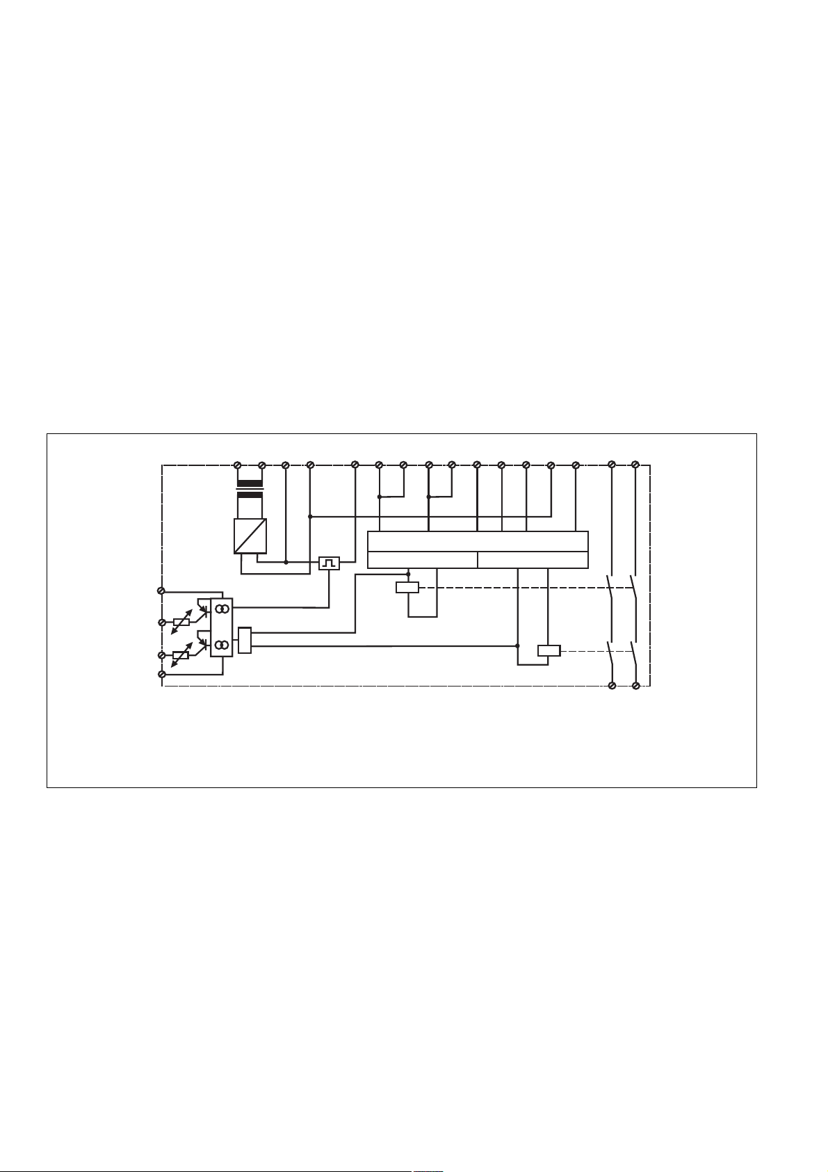
A1 A2
~
G1
Y31
Y35
Y32
Y30
A: Einschaltlogik, zyklscher Test, Steuerlogik
1: Kanal 1
2: Kanal 2
Fig. 1: Innenschaltbild/Internal Wiring Diagram/Schéma de principe
Betriebsarten:
• Einkanaliger Betrieb:
Eingangsbeschaltung nach VDE 0113
und EN 60204, keine Redundanz im
Eingangskreis; Erdschlüsse im Tasterkreis werden erkannt.
• Zweikanaliger Betrieb: Redundanter
Eingangskreis; Erdschlüsse im Tasterkreis und Querschlüsse zwischen den
Tasterkontakten werden erkannt.
• Automatischer Start: Gerät ist aktiv,
sobald der Eingangskreis geschlossen ist.
• Manueller Start: Gerät ist erst dann aktiv,
wenn ein Starttaster betätigt wird.
• Schaltmattenbetrieb (s. Anschlussbeispiele): Bei Belastung der Schaltmatte
wird ein Querschluss zwischen den
Eingängen gebildet und die interne
Fehlererkennung spricht an; K1 und K2
fallen in die Ruhestellung zurück, die
Sicherheitskontakte 13-14/23-24 werden
redundant geöffnet. Die LED
“EXT.FAULT” leuchtet. Die Versorgungsspannung liegt weiter an. Nach Wegfall
B1
B2
=
&
F1
A: Operating Logic, Cycle Test, Control
Logic
1: Channel 1
2: Channel 2
Operating Modes:
• Single-channel operation: Input wiring
according to VDE 0113 and EN 60204, no
redundancy in the input circuit. Earth
faults are detected in the emergency stop
circuit.
• Two-channel operation: Redundancy in
the input circuit; Earth faults in the
emergency stop circuit and shorts across
the emergency stop pushbutton are
detected.
• Automatic reset: Unit is active, as soon
as the input circuit is closed.
• Manual reset: Unit is only active, when a
reset button has been pressed.
• Safety Mat operation (see connection
example): If there is a load on the safety
mat, a short-circuit occurs between the
inputs and the internal fault recognition
reacts: K1 and K2 de-energise, the safety
contacts 13-14/23-24 are opened
redundantly. The LED ‘EXT.FAULT’ is lit.
The supply voltage is still present. Once
the short is removed , the unit is ready for
S12
K1
Y2S11 S32S31 S33
Y1
A
1
S21 S22S34
2
K2
A: logique de commande et d’entrée, test
cyclique
1 : canal 1
2 : canal 2
Mode de fonctionnements :
• Commande par 1 canal: conforme aux
prescriptions de la norme EN 60204, pas
de redondance dans le circuit d'entrée.La
mise à la terre du circuit d'entrée est
détectée.
• Commande par 2 canaux: circuit d’entrée
redondant. La mise à la terre et les
courts-circuits entre les contacts sont
détectés.
• Réarmement automatique: le relais est
activé dès la fermeture des canaux
d’entrée.
• Réarmement manuel: le relais n’est activé
qu’après une impulsion sur le poussoir de
validation.
• Tapis et bourelets sensibles (voir
exemple de branchement) : En cas de
pression sur le tapis (ou bourelet), un
court-circuit se crée entre les canaux
d’entrée et les relais K1 et K2 retombent.
Les contacts de sécurité 13-14/23-24
s’ouvrent.La LED “EXT.FAULT” est
allumée. La tension d’alimentation est
13 23
14 24
- 2 -

der Störungsursache ist das Gerät nach
Ablauf der Wiederbereitschaftszeit nach
Querschluss (siehe techn. Daten) wieder
betriebsbereit.
Nur für PNOZ 16S: Der Halbleiterausgang Y35 sperrt, wenn die Sicherung
ausgelöst hat.
• Kontaktvervielfachung und -verstärkung
durch Anschluss von externen Schützen
use after the recovery time following short
across contacts (see techn. data) has
elapsed.
PNOZ 16 S only: If the fuse is triggered,
the semiconductor output Y35 goes low.
• Increase in the number of available
contacts by connection of external
contactors/relays.
toujours présent. Après disparition du
court-circuit, le relais est à nouveau prêt
à fonctionner au bout du temps de remise
en service après court-circuit (voir
charactéristiques techniques).
Uniquement pour PNOZ 16S: la sortie
statique Y35 est bloquée, lorsque le
fusible électronique déclenche.
• Augmentation du nombre de contacts ou
du pouvoir de coupure par l'utilisation de
contacteurs externes
Montage
Das Sicherheitsschaltgerät muss in einen
Schaltschrank mit einer Schutzart von mind.
IP54 eingebaut werden. Zur Befestigung auf
einer Normschiene hat das Gerät ein
Rastelement auf der Rückseite.
Sichern Sie das Gerät bei Montage auf
einer senkrechten Tragschiene (35 mm)
durch ein Halteelement wie z. B. Endhalter
oder Endwinkel.
Inbetriebnahme
Beachten Sie bei der Inbetriebnahme:
• Nur die Ausgangskontakte 13-14/23-24
sind Sicherheitskontakte.
• Vor die Ausgangskontakte eine
Sicherung (siehe techn. Daten)
schalten, um das Verschweißen der
Kontakte zu verhindern.
• Berechnung der max. Leitungslänge I
am Eingangskreis:
R
lmax
=
I
max
Rl / km
R
= max. Gesamtleitungswiderstand
lmax
(s. technische Daten)
Rl /km = Leitungswiderstand/km
Da die Funktion Querschlusserkennung
nicht einfehlersicher ist, wird sie von Pilz
während der Endkontrolle geprüft. Eine
Überprüfung nach der Installation des
Geräts ist wie folgt möglich:
1. Gerät betriebsbereit (Ausgangs-
kontakte geschlossen)
2. Die Testklemmen S12-S22 zur
Querschlussprüfung kurzschließen.
3. Die Sicherung im Gerät muss auslösen
und die Ausgangskontakte öffnen.
4. Sicherung wieder zurücksetzen: den
Kurzschluss entfernen.
• Leitungsmaterial aus Kupferdraht mit
einer Temperaturbeständigkeit von
60/75 °C verwenden.
• Sorgen Sie beim Anschluss von magnetisch wirkenden, auf Reedkontakten
basierenden Näherungsschaltern dafür,
dass der max. Einschaltspitzenstrom (am
Eingangskreis) den Näherungsschalter
nicht überlastet.
• Angaben im Abschnitt “Technische
Daten” unbedingt einhalten.
Ablauf:
• Versorgungsspannung an den Klemmen
AC: A1 und A2 bzw. DC: B1 (+) und B2
(-) anlegen
- DC: Klemme B2 (-) mit geerdeter Seite
der Versorgungsspannung verbinden
- AC: B2 mit Schutzleitersystem verbin-
den
• Rückführkreis schließen: Brücke an
Y1-Y2 oder externe Schütze anschließen
• Startkreis schließen:
- Automatischer Start: S33-S34 brücken
- Manueller Start: Taster an S33-S34
max
Installation
The safety relay must be panel mounted
(min. IP54). There is a notch on the rear of
the unit for DIN-Rail attachment.
If you are installing the unit on to a vertical
DIN rail, ensure that it is mounted securely
by using a retaining bracket or an end angle.
Operation
Please note for operation:
• Only the output contacts 13-14/23-24 are
safety contacts
• To prevent a welding together of the
contacts, a fuse (see technical data)
must be connected before the output
contacts.
• Calculating the max. cable length I
the input circuit:
R
I
max
R
Technical details)
lmax
=
Rl / km
= max. overall cable resistance (see
lmax
Rl /km = cable resistance/km
As the function for detecting shorts across
the inputs is not failsafe, it is tested by
Pilz during the final control check.
However, a test is possible after installing
the unit and it can be carried out as
follows:
1. Unit ready for operation (output
contacts closed)
2. Short circuit the test (connection)
terminals S12-S22 for detecting shorts
across the inputs
3. The unit‘s fuse must be triggered and
the output contacts must open.
4. Reset the fuse: remove the short
circuit.
• Use copper wire that can withstand
60/75 °C.
• When connecting magnetically operated,
reed proximity switches, ensure that the
max. peak inrush current (on the input
circuit) does not overload the proximity
switch.
• Important details in the section "Technical
Data" should be noted and adhered to.
To operate:
• Supply operating voltage to terminals
AC: A1 and A2/DC: B1 (+) and B2 (-)
- DC: Connect terminal B2 (-) with the
earthed side of the operating voltage
- AC: Connect B2 with the system earth
• Close the feedback control loop: Bridge
Y1 - Y2 or connect external contactors/
relays.
• Close the reset circuit.
- Automatic reset: Bridge S33 - S34
- Manual reset: Connect button on S33 -
S34 (no bridge on S33 - S34).
max
at
Montage
Le relais doit être installé dans une armoire
équipée d'une protection IP54. Sa face
arrière permet un montage rapide sur rail
DIN.
Immobilisez l’appareil monté sur un profilé
support vertical (35 mm) à l’aide d’un
élément de maintien comme par ex. un
support ou une équerre terminale.
Mise en oeuvre
Remarques préliminaires:
• Seuls les contacts de sortie 13-14/23-24
sont des contacts de sécurité
• Protection des contacts de sortie par
des fusibles (voir charactéristiques
techniques) pour éviter leur soudage.
• Calcul de la longueur de conducteur I
sur le circuit d’entrée :
R
I
max
R
(voir les caractéristiques techniques)
lmax
=
Rl / km
= Résistivité de câblage totale max.
lmax
Rl /km = résistance du câble/km
La fonction de détection de court-circuit
est testé par Pilz lors du contrôle final. Un
test sur site est possible de la façon
suivante:
1. Appareil en fonction (contacts de sortie
fermés)
2. Court-circuiter les bornes de
raccordement nécessaires au test
S12-S22
3. Le fusible interne du relais doit
déclencher et les contacts de sortie
doivent s‘ouvrir.
4. Réarmement du fusible: enlever le
court-circuit.
• Utiliser uniquement des fils de cablâge en
cuivre 60/75 °C.
• Lors du raccordement de détecteurs de
proximité magnétiques, basés sur des
contacts Reed, veuillez vous assurer que
le courant de crête max. à la mise sous
tension (sur le circuit d'entrée) ne
surcharge pas les détecteurs de
proximité.
• Respectez les données indiquées dans les
caractéristiques techniques.
Mise en oeuvre :
• Ramener la tension d’alimentation sur les
bornes A1 et A2 en AC ou B1(+) et B2 (-)
en DC
- DC: borne B2 (-) à relier au 0 V
- AC: B2 à relier à la terre
• Fermer la boucle de retour:
pont entre Y1-Y2 ou câblage des
contacts externes.
• Fermer le circuit de réarmement:
- réarmement automatique: pontage des
bornes S33-S34.
max
- 3 -
anschließen (keine Brücke an S33S34)
• Eingangskreis schließen:
- Einkanalig: S21-S22 und S31-S32
brücken; Öffnerkontakt von
Auslöselement an S11 und S12
anschließen.
- Zweikanalig: Öffnerkontakt von
Auslöseelement an S31-S32/S21-S22
anschließen; Brücke an S11-S12
Die Sicherheitskontakte sind aktiviert
(geschlossen). Die Statusanzeigen von
Kanal 1 (“CH.1”) und Kanal 2 (“CH.2”)
leuchten. Das Gerät ist betriebsbereit.
Wird der Eingangskreis geöffnet, öffnen die
Sicherheitskontakte 13-14 und 23-24.
Die Statusanzeige erlischt.
Wieder aktivieren:
• Eingangskreis schließen
• Bei manuellem Start zusätzlich Taster
zwischen S33 und S34 betätigen
Die Statusanzeigen leuchten wieder, die
Sicherheitskontakte sind geschlossen.
• Close the input circuit:
- Single channel: Bridge S21-S22 and
S31-S32; Connect N/C contact from
input device to S11 and S12.
- Two channel: Connect N/C contact
from input device to S31-S32/S21-S22;
Bridge S11-S12.
The safety contacts are activated (closed).
The status indicators of channel 1 (“CH.1”)
and channel 2 (“CH.2”) illuminate. The unit
is ready for operation.
If the input circuit is opened, the safety
contacts 13-14 and 23-24 open. The status
indicators go out.
Reactivation:
• Close the input circuit.
• With manual reset, the button between
S33 - S34 must also be pressed.
The status indicators light up again, the
safety contacts are closed.
- réarmement manuel: câblage d'un
poussoir sur S33-S34 (pas de
pontage).
• Fermer le circuit d'entrée:
- commande par 1 canal: câblage du
contact à ouverture entre S11 et S12,
pontage de S31-S32 et S21-S22
- commande par 2 canaux : câblage des
contacts à ouverture entre S31-S32/
S21-S22, pontage de S11-S12.
Les contacts de sécurité sont fermés. Les
LEDs "CH.1" et "CH.2" sont allumées. Le
relais est activé.
Si le circuit d'entrée est ouvert, les contacts
de sécurité 13-14/23-24 s'ouvrent. Les
LEDs "K1" et "K 2" s'éteignent.
Remise en route :
• fermer le circuit d'entrée
• en cas de réarmement manuel, action sur
le poussoir de réarmement
Les affichages d’état s’allument à nouveau.
Les contacts de sécurité sont fermées.
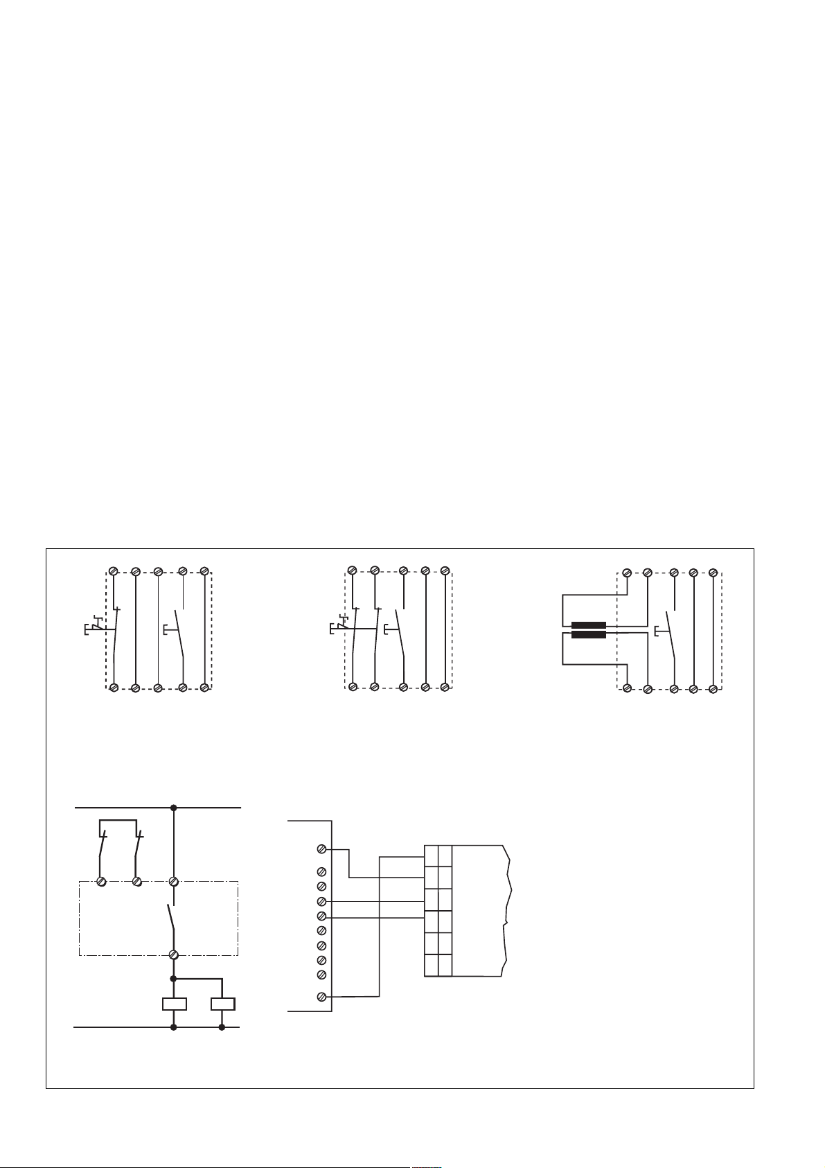
Anschlussbeispiele
Beachten Sie bei:
Fig. 4: Das Gesamtsystem PNOZ 16(S) und
die Schaltmatte oder Schaltleiste muss nach
der Produktnorm DIN EN 1760-1 bzw.
EN 1760-2 bewertet werden.
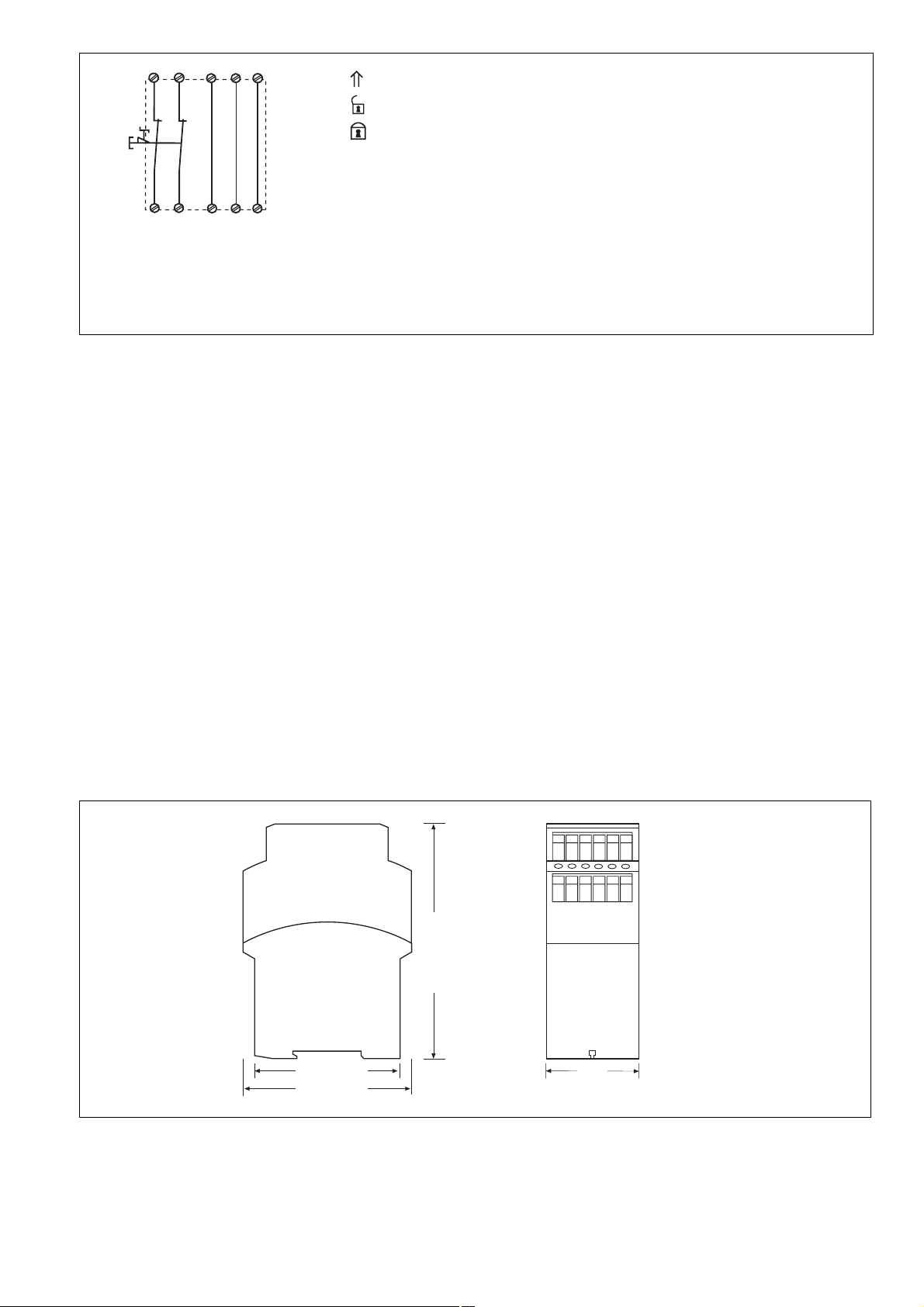
Fig. 7: Das Gerät startet bei Spannungsausfall und -wiederkehr automatisch.
Verhindern Sie einen unerwarteten Wiederanlauf durch externe Schaltungsmaßnahmen.
S11 S33
S31
S21
S1
S12
S32
S22
Fig. 2: Eingangskreis einkanalig; Not-HaltBeschaltung; manueller Start/Single
channel input; Emergency Stop wiring;
manual reset/commande par 1 canal;
circuit d’arrêt d’urgence; réarmement
manuel
1L1
K5
K4
13Y1 Y2
14
K4 K5
1L2
Fig. 5: Anschlussbeispiel für externe
Schütze/Connection of external contactors/
relays/câblage des contacteurs externes
Y1
S3
S34
Y2
Connection Examples
Please note for:
Fig. 4: The whole system PNOZ 16(S) and
the safety mat or safe edge must be
assessed in accordance with the product
standard DIN EN 1760-1 / EN 1760-2.
Fig. 7: the device starts automatically after
loss of power. You should prevent an
unintended start-up by using external
circuitry measures.
S31 S21
S1
S32
Fig. 3: Eingangskreis zweikanalig; Not-HaltBeschaltung; manueller Start/Two channel
input; Emergency Stop wiring; manual
reset/commande par 2 canaux;
circuit d’arrêt d’urgence; réarmement manuel
SPS
+ 24V
E0.0
E0.1
E0.2
E0.3
A0.0
A0.1
A0.2
A0.3
PLC API
0V
Fig. 6: Anschlussbeispiel für Halbleiterausgänge/Connection of semiconductor
outputs/câblage des sorties statiques
S22
S33
S11
Y1
S3
S12
S34
Y2
S33
PNOZ 16S
S34 14 24 B2 A2
Y32Y31Y30
Y35
Exemples de branchement
Remarques :
Fig. 4 : le système complet PNOZ 16(S) et le
tapis ou le bord sensible doit être estimé
selon la norme produit DIN EN 1760-1 ou
EN 1760-2.
Fig. 7 : l’appareil se réarme automatiquement
après une coupure et une remise sous
tension. Evitez tout risque de redémarrage
par un câblage externe approprié.
S31
S32
S22
S21
Fig. 4: Schaltmatte, Schaltleiste/Safety
mat,Safe edge/Tapis,bourelets
sensibles
Y1Y2S11
S33
S3
S34
S12
- 4 -
S1
S31 S21
S32
S22
S34Y1Y2
S33
S11
S12
Fig. 7: Eingangskreis zweikanalig; Not-HaltBeschaltung; automatischer Start/Two
channel input; Emergency Stop wiring;
automatic reset/commande par 2 canaux;
circuit d’arrêt d’urgence; réarmement
automatique
betätigtes Element/Switch activated/Elément actionné
Tür offen/Gate open/Porte ouverte
Tür geschlossen/gate closed/Porte fermée
S1/S2: Not-Halt- bzw. Schutztürschalter/Emergency Stop Button, Safety Gate Limit
Switch/Pousssoir AU, détecteurs de position
S3: Starttaster/Reset Button/Pousssoir de réarmement
S4: Not-Halt-Taster/Emergency Stop Button/Pousssoir AU
Fehler - Störungen
• Erdschluss bei Wechselspannung: Die
Versorgungsspannung bricht zusammen
und die Sicherheitskontakte werden
geöffnet.
• Erdschluss bei Gleichspannung: Eine
elektronische Sicherung bewirkt das
Öffnen der Ausgangskontakte; die LED
“EXT.FAULT” leuchtet auf.
• Wird im Schaltmattenbetrieb die Schaltmatte betätigt, fallen die Relais ab und
die LED “EXT.FAULT” leuchtet während
der Betätigung. Eine Aktivierung ist in
diesem Zustand nicht möglich. Ist die
Schaltmatte wieder im Ruhezustand,
kann das Gerät wieder aktiviert werden.
Schaltmatten-Auslösung und Querschlusserkennung sind nicht nullspannungssicher.
Nach Wegfall der Störungsursache ist das
Gerät nach Ablauf der Wiederbereitschaftszeit nach Querschluss (siehe
techn. Daten) wieder betriebsbereit.
• Fehlfunktionen der Kontakte: Bei
Faults/Disturbances
• Earth faults with AC units: The supply
voltage is interrupted and the safety
contacts open.
• Earth faults with DC units: An electronic
fuse causes the output contacts to open;
The LED “EXT.FAULT” illuminates.
• If any connected Safety mats are
operated, the relays drop out and the LED
“EXT.FAULT” illuminates during
operation. Activation is not possible in
this condition. If the Safety mat returns to
its rest condition, the unit can be activated
once more. Safety mat triggering and
recognition of shorts across contacts are
not non-volatile.
Once the cause of the disturbance is
removed, the unit is ready for use after
the recovery time following short across
contacts(see techn. data) has elapsed.
• Faulty contact functions: In the case of
welded contacts, no further activation is
possible following an opening of the input
circuit.
verschweißten Kontakten ist nach Öffnen
des Eingangskreises keine neue Aktivierung möglich.
Abmessungen in mm/Dimensions in mm/Dimensions en mm
Erreurs- Défaillances
• Mise à la terre (en AC): la tension
d’alimentation s’écroule et les contacts de
sécurité s’ouvrent.
• Mise à la terre (en DC): le fusible
électronique déclenche et provoque
l’ouverture des contacts de sécurité; la
LED “EXT.FAULT” s’allume.
• En cas d’utilisation avec un tapis sensible, une pression sur le tapis provoque la
retombée des relais internes et la LED
“EXT.FAULT” s’allume. Le réarmement
du relais n’est alors possible qu’après la
disparition de la pression sur le tapis. Le
déclenchement du relais et la détection
de court-circuit ne sont pas mémorisés.
Après la disparition du défaut, le relais est
à nouveau prêt à fonctionner au bout du
temps de remise en service après courtcircuit (voir charactéristiques techniques).
• Défaut d'un contact: en cas de collage
d'un contact après ouverture du circuit
d'entrée, un nouvel réarmement est
impossible.
75 (2.95")
87 (3.42")
122 (4.8")
45
(1.77")
- 5 -

Technische Daten
Technical Data
Caractéristiques techniques
Elektrische Daten
Versorgungsspannung U
B
Spannungstoleranz
Leistungsaufnahme bei U
B
Frequenzbereich AC
Restwelligkeit DC
Spannung und Strom an
Eingangskreis
Start- und Rückführkreis
Anzahl der Ausgangskontakte
Sicherheitskontakte (S)
Gebrauchskategorie nach
EN 60947-4-1
EN 60947-5-1(DC13:
6 Schaltspiele/Min.)
Kontaktmaterial
Kontaktabsicherung extern
EN 60947-5-1 (IK = 1 kA)
Schmelzsicherung flink
Schmelzsicherung träge
Sicherungsautomat
Charakteristik
Halbleiterausgänge (kurzschlussfest)
Externe Spannungsversorgung
Spannungstoleranz
Schaltmattenwiderstand
Max. Gesamtleitungswiderstand R
Eingangskreise
lmax
einkanalig
zweikanalig mit
Querschlusserkennung
Min. Eingangswiderstand im
Einschaltmoment
Sicherheitstechnische Kenndaten
der Sicherheitsausgänge
PL nach EN ISO 13849-1
Kategorie nach EN 954-1
SIL CL nach EN IEC 62061
PFH nach EN IEC 62061
SIL nach IEC 61511
PFD nach IEC 61511
tM in Jahren
Zeiten
Einschaltverzögerung
automatischer Start
automatischer Start nach Netz-Ein
manueller Start
Rückfallverzögerung
bei Not-Halt
bei Netzausfall
Wiederbereitschaftszeit bei max.
Schaltfrequenz 1/s
nach Not-Halt
nach Netzausfall
Gleichzeitigkeit Kanal 1 und 2
Überbrückung bei
Spannungseinbrüchen
Electrical data
Supply Voltage U
B
Voltage Tolerance
Power consumption at U
B
Frequency range AC
Residual Ripple DC
Voltage and Current at
Input circuit
Reset circuit and feedback loop
Number of output contacts
Safety contacts (N/O)
Utilization category in accordance with
EN 60947-4-1
EN 60947-5-1(DC13: 6 cycles/min)
Contact material
External contact fuse protection
EN 60947-5-1 (IK = 1 kA)
Blow-out fuse quick
Blow-out fuse slow
Safety cut-out
Cvaracteristic
semiconductor outputs (short circuitproof)
external supply voltage
voltage tolerance
Safety mat resistance
Max. overall cable resistance R
input circuits
lmax
Single-channel
dual-channel with detection of
shorts across contacts
Min. input resistance in the starting
torque
Safety-related characteristics of
the safety outputs
PL in accordance with
EN ISO 13849-1
Category in accordance with
EN 954-1
SIL CL in accordance with
EN IEC 62061
PFH in accordance with
EN IEC 62061
SIL in accordance with IEC 61511
PFD in accordance with IEC 61511
tM in years
Times
Switch-on delay
automatic reset
automatic reset after power-ON
manual reset
Delay-on De-Energisation
at E-STOP
with power failure
Recovery time at max. switching
frequency 1/s
after E-STOP
after power failure
Simultaneity channel 1 and 2
Supply interruption before de-
energisation
Données électriques
Tension d’alimentation U
B
Plage de la tension d’alimentation
Consommation pour U
B
Fréquence AC
Ondulation résiduelle DC
Tension et courant du
Circuit d’entrée
Circuit de réarmement et boucle
de retour
Nombre de contacts de sortie
contacts de sécurité (F)
Catégorie d’utilisation selon
EN 60947-4-1
EN 60947-5-1(DC13:
6 manoeuvres/min)
Matériau contact
Protection des contacts externe
EN 60947-5-1 (IK = 1 kA)
Fusibles rapide
Fusibles normal
Dijoncteur
Caractéristique
sorties statiques (protegées contre
c.c.)
tension d'alimentation externe
plage de la tension
Résistivité du tapis sensible
Résistance de câblage totale max.
R
circuits d'entrée
lmax
Commande par 1 canal
commande par 2 canaux avec
détection des courts-circuit
Résistance d'entrée min. au moment
de la mise en marche
Caractéristiques techniques de
sécurité des sorties de sécurité
PL selon EN ISO 13849-1
Catégorie selon EN 954-1
SIL CL selon EN IEC 62061
PFH selon EN IEC 62061
SIL selon IEC 61511
PFD selon IEC 61511
tM en années
Temporisations
Temps de réarmement
réarmement automatique
réarmement automatique après
mise sous tension
réarmement manuel
Temps de retombée
en cas d'arrêt d'urgence
en cas de coupure d'alimentation
Temps de remise en service en cas de
fréquence de commutation max. 1/s
arrêt d'urgence
après une coupure d'alimentation
Désynchronisme canal 1 et 2
Tenue aux micro-coupures
24 V DC
24 V, 42 V, 48 V, 110 V,
115 V, 120 V, 230 V,
240 V AC
-15 ... +10 %
DC: 2,0 W, AC: 3,5 VA
50 ... 60 Hz
20 %
24 V DC: 25 mA
24 V DC: 25 mA
2
AC1: 240 V/0,01 ... 8 A/
2000 VA
DC1: 24 V/0,01 ... 8 A/
200 W
AC15: 230 V/5 A;
DC13: 24 V/6 A
AgSnO2+ 0,2 µm Au
10 A
6 A
24 V AC/DC: 6 A
B/C
24 V DC, 20 mA
24 V DC
-15 % / +10 %
80 Ohm
40 Ohm
80 Ohm
49 Ohm
PL e (Cat. 4)
Cat. 4
SIL CL 3
2,31E-09
SIL 3
2,03E-06
20
typ. 230 ms, max. 350 ms
typ. 310 ms, max. 450 ms
typ. 230 ms, max. 350 ms
typ. 18 ms, max. 30 ms
typ. 50 ms, max. 80 ms
50 ms
100 ms
∞
20 ms
- 6 -

Umweltdaten
EMV
Schwingungen nach EN 60068-2-6
Frequenz
Amplitude
Klimabeanspruchung
Luft- und Kriechstrecken nach
EN 60947-1
Verschmutzungsgrad
Überspannungskategorie
Bemessungsisolationsspannung
Bemessungsstoßspannungs-
festigkeit
Umgebungstemperatur
Lagertemperatur
Schutzart
Einbauraum (z. B. Schaltschrank)
Gehäuse
Klemmenbereich
Mechanische Daten
Gehäusematerial
Gehäuse
Front
Querschnitt des Außenleiters
(Schraubklemmen)
1 Leiter, flexibel
2 Leiter gleichen Querschnitts, flexi-
bel mit Aderendhülse, ohne
Kunststoffhülse
ohne Aderendhülse oder mit TWIN-
Aderendhülse
Anzugsdrehmoment für
Schraubklemmen
Abmessungen H x B x T
Einbaulage
Gewicht
Environmental data
EMC
Vibration to EN 60068-2-6
Frequency
Amplitude
Climate Suitability
Airgap Creepage in accordance with
EN 60947-1
Pollution degree
Overvoltage category
Rated insulation voltage
Rated impulse withstand voltage
Ambient temperature
Storage temperature
Protection type
Mounting (eg. panel)
Housing
Terminals
Mechanical data
Housing material
Housing
Front panel
Cable cross section (screw
terminals)
1 core, flexible
2 core, same cross section flexible
with crimp connectors, without
insulating sleeve
without crimp connectors or with
TWIN crimp connectors
Torque setting for screw terminals
Dimensions H x W x D
Fitting Position
Weight
Données sur l'environnement
CEM
Vibrations selon EN 60068-2-6
Frequence
Amplitude
Conditions climatiques
Cheminement et claquage selon
EN 60947-1
Niveau d'encrassement
Catégorie de surtensions
Tension assignée d’isolement
Tension assignée de tenue aux
chocs
Température d’utilisation
Température de stockage
Indice de protection
Lieu d'implantation (ex. armoire)
Boîtier
Bornes
Données mécaniques
Matériau du boîtier
Boîtier
Face avant
Capacité de raccordement
(borniers à vis)
1 conducteur souple
2 conducteurs de même diamètre
souple avec embout, sans chapeau
plastique
souple sans embout ou avec
embout TWIN
Couple de serrage (borniers à vis)
Dimensions H x P x L
Position de travail
Poids
EN 60947-5-1,
EN 61000-6-2
10 ... 55 Hz
0,35 mm
EN 60068-2-78
2
III
250 V
4 kV
-10 ... + 55 °C
-40 ... +85 °C
IP54
IP40
IP20
PPO UL 94 V0
ABS UL 94 V0
0,2 ... 4,0 mm2, 24 ... 10 AWG
0,2 ... 2,5 mm2, 24 ... 14 AWG
0,2 ... 2,5 mm2, 24 ... 14 AWG
0,6 Nm
87 x 45 x 121 mm
beliebig/any/indifférente
350 g
Es gelten die 2008-06 aktuellen Ausgaben
der Normen
The version of the standards current at
2008-06 shall apply
Se référer à la version des normes en
vigeur au 2008-06.
Konventioneller thermischer Strom bei gleichzeitiger Belastung mehrerer Kontakte/Conventional thermal current
while loading several contacts/Courant thermique conventionnel en cas de charge sur plusieurs contacts (AC1, DC1)
Anzahl der Kontakte/number of contacts/nombre des contacts 2 1
Ith (A) pro Kontakt bei Versorgungsspannung DC/per contact
with operating voltage DC/par contact pour tension d’alimentation DC 6,0 8,0
Ith (A) pro Kontakt bei Versorgungsspannung AC/per contact
with operating voltage AC/par contact pour tension d’alimentation AC 6,0 8,0
Um ein Versagen der Geräte zu verhindern,
an allen Ausgangskontakten für eine ausreichende Funkenlöschung sorgen. Bei
kapazitiven Lasten sind eventuell auftretende
Stromspitzen zu beachten. Bei DC-Schützen
Freilaufdioden zur Funkenlöschung einsetzen, um die Lebendauer der Schütze zu
erhöhen.
To prevent failure of the unit, all output
contacts should be fused adequately. With
capacative loads, possible current peaks are
to be avoided. With DC contactors/relays
use suitable spark suppression to ensure
extended life of the contactors/relays.
Prévoir un dispositif d’extinction d’arc sur les
contacts de sortie pour éviter un éventuel
disfonctionnement du relais.
Tenir compte des pointes d’intensité en cas
de charge capacitive. Equiper les
contacteurs DC de diodes de roue libre .
- 7 -

Bestelldaten/Order reference/Caractéristiques
Typ/
Type/
Type
PNOZ 16
PNOZ 16
PNOZ 16
PNOZ 16
PNOZ 16
PNOZ 16
PNOZ 16
PNOZ 16
PNOZ 16S
PNOZ 16S
PNOZ 16S
PNOZ 16S
PNOZ 16S
PNOZ 16S
PNOZ 16S
PNOZ 16S
Merkmale/
Features/
Caractéristiques
24 V AC/DC
42 V AC
48 V AC
110 V AC
115 V AC
120 V AC
230 V AC
240 V AC
24 V AC/DC
42 V AC
48 V AC
110 V AC
115 V AC
120 V AC
230 V AC
240 V AC
24 V DC
24 V DC
24 V DC
24 V DC
24 V DC
24 V DC
24 V DC
24 V DC
24 V DC
24 V DC
24 V DC
24 V DC
24 V DC
24 V DC
Klemmen/
Terminals/
Borniers
Schraubklemmen/screw terminals/borniers à vis
Schraubklemmen/screw terminals/borniers à vis
Schraubklemmen/screw terminals/borniers à vis
Schraubklemmen/screw terminals/borniers à vis
Schraubklemmen/screw terminals/borniers à vis
Schraubklemmen/screw terminals/borniers à vis
Schraubklemmen/screw terminals/borniers à vis
Schraubklemmen/screw terminals/borniers à vis
Schraubklemmen/screw terminals/borniers à vis
Schraubklemmen/screw terminals/borniers à vis
Schraubklemmen/screw terminals/borniers à vis
Schraubklemmen/screw terminals/borniers à vis
Schraubklemmen/screw terminals/borniers à vis
Schraubklemmen/screw terminals/borniers à vis
Schraubklemmen/screw terminals/borniers à vis
Schraubklemmen/screw terminals/borniers à vis
Bestell-Nr./
Order no./
Référence
774 060
774 061
774 062
774 063
774 064
774 065
774 066
774 067
774 070
774 071
774 072
774 073
774 074
774 075
774 076
774 077
Lebensdauer der Ausgangsrelais/Service Life of Output relays/Durée de vie des relais de sortie
10
AC15: 230 V
DC1: 24 V
1
Courant coupé (A)
Nennbetriebstrom (A)
Nominal operating current (A)
0.1
10 100 1000 10000
EG-Konformitätserklärung:
Diese(s) Produkt(e) erfüllen die Anforderungen der Richtlinie 2006/42/EG über
Maschinen des europäischen Parlaments
und des Rates.
Die vollständige EG-Konformitätserklärung
finden Sie im Internet unter www.pilz.com
Bevollmächtigter: Norbert Fröhlich,
Pilz GmbH & Co. KG, Felix-Wankel-Str. 2,
73760 Ostfildern, Deutschland
DC13: 24 V
Schaltspielzahl x 10
Nombre de manvres x 10
Cycles x 10
AC1: 230 V
3
3
3
EC Declaration of Conformity:
This (these) product(s) comply with the
requirements of Directive 2006/42/EC of the
European Parliament and of the Council on
machinery.
The complete EC Declaration of Conformity
is available on the Internet at www.pilz.com
Authorised representative: Norbert Fröhlich,
Pilz GmbH & Co. KG, Felix-Wankel-Str. 2,
73760 Ostfildern, Germany
Déclaration de conformité CE :
Ce(s) produit(s) satisfait (satisfont) aux
exigences de la directive 2006/42/CE
relative aux machines du Parlement
Européen et du Conseil.
Vous trouverez la déclaration de conformité
CE complète sur notre site internet
www.pilz.com
Représentant : Norbert Fröhlich,
Pilz GmbH & Co. KG, Felix-Wankel-Str. 2,
73760 Ostfildern, Allemagne
Technischer Support
+49 711 3409-444 +49 711 3409-444
...
In vielen Ländern sind wir durch
unsere Tochtergesellschaften und
Handelspartner vertreten.
Nähere Informationen entnehmen
Sie bitte unserer Homepage oder
nehmen Sie Kontakt mit unserem
Stammhaus auf.
Technical support
... ...
In many countries we are
represented by our subsidiaries
and sales partners.
Please refer to our Homepage
for further details or contact our
headquarters.
Assistance technique
+49 711 3409-444
Nos filiales et partenaires
commerciaux nous représentent
dans plusieurs pays.
Pour plus de renseignements,
consultez notre site internet ou
contactez notre maison mère.
- 8 -
www
www.pilz.com
Pilz GmbH & Co. KG
Felix-Wankel-Straße 2
73760 Ostfildern, Germany
Telephone: +49 711 3409-0
Telefax: +49 711 3409-133
E-Mail: pilz.gmbh@pilz.de
Originalbetriebsanleitung/Original instructions/Notice originale
18673-6NL-05-2010-08 Printed in Germany

18673-6NL-05
PNOZ 16, PNOZ 16S
4 E Instrucciones de uso
4 I Istruzioni per l`uso
4 NL Gebruiksaanwijzing
• El dispositivo debe ser instalado y puesto
Prescripciones de seguridad
en funcionamiento exclusivamente por
personas que estén familiarizadas con
estas instrucciones de uso y con las
prescripciones vigentes relativas a la
seguridad en el trabajo y a la prevención
de accidentes. Observar tanto las
prescripciones VDE como las
prescripciones locales, especialmente en
lo que se refiere a las medidas de
protección.
• Durante el transporte, el almacenaje y el
funcionamiento, atenerse a las
condiciones conforme a EN 60068-2-6
(ver datos técnicos). Una vez finalizada
su vida útil, hay que eliminar el dispositivo
de forma apropiada.
• La garantía se pierde en caso de que se
abra la carcasa o se lleven a cabo
remodelaciones por cuenta propia.
• Montar el dispositivo dentro de un
armario de distribución; en caso contrario
es posible que el polvo y la suciedad
puedan afectar el funcionamiento.
• Hay que cuidar de que haya un
conexionado de seguridad suficiente en
todos los contactos de salida con cargas
capacitivas e inductivas.
Campo de aplicación adecuado
El dispositivo sirve para la interrupción
orientada a la seguridad de un circuito de
corriente de seguridad. El dispositivo de
seguridad cumple los requisitos de las normas
EN 60947-5-1, EN 60204-1 y VDE 0113-1 y
puede utilizarse en aplicaciones con
• pulsadores de parada de emergencia
• puertas protectoras
• alfombras de seguridad
• perfiles sensibles de seguridad
El dispositivo no es adecuado para el
aseguramiento de coberturas sin contacto, ya
que no es posible ningún un arranque
dinámico.
Norme di sicurezza
• Il dispositivo può venire installato e messo
in funzione solo da persone che
conoscono bene le presenti istruzioni per
l’uso e le disposizioni vigenti riguardo alla
sicurezza di lavoro e all’antinfortunistica.
Osservare le disposizioni della VDE
(Associazione tedesca degli Ingegneri)
nonché le norme locali, soparada de
emergencialprattutto per quanto riguarda
le misure preventive di protezione.
• Durante il trasporto, l’immagazzinamento
e il funzionamento attenersi alle
condizioni prescritte dalla norma
EN 60068-2-6 (v. Dati tecnici). Al termine
della propria durata, smaltire il dispositivo
in conformità alle norme vigenti.
• Se viene aperta la custodia oppure se
vengono apportate delle modifiche in
proprio decade qualsiasi diritto di
garanzia.
• Montare il dispositivo in un armadio
elettrico; altrimenti la polvere e l’umidità
possono pregiudicare le funzioni.
• Preoccuparsi che tutti i contatti di uscita
sui carichi capacitivi e induttivi siano
dotati di un cablaggio protettivo
sufficiente.
Uso previsto
Il modulo di sicurezza consente
l'interruzione sicura di un circuito di
sicurezza. Il modulo di sicurezza risponde ai
requisiti secondo EN 60947-5-1, EN 602041 e VDE 0113-1 e può essere utilizzato in
applicazioni con
• pulsanti di arresto d'emergenza
• ripari mobili
• tappeti di sicurezza
• bumper
L’unità non è adatta a garantire la
protezione di barriere senza contatto, perciò
non è possibile nessun avvio dinamico.
Veiligheidsvoorschriften
• Het apparaat mag uitsluitend worden
geïnstalleerd en in bedrijf genomen door
personen die vertrouwd zijn met deze
gebruiksaanwijzing en met de geldende
voorschriften op het gebied van
arbeidsveiligheid en ongevallenpreventie.
Neemt u de van toepassing zijnde
Europese richtlijnen en de plaatselijke voorschriften in acht, in het bijzonder m.b.t.
veiligheidsregels.
• Neem bij transport, opslag en in bedrijf de
richtlijnen volgens EN 60068-2-6 in acht
(zie technische gegevens). Het apparaat na
afloop van zijn levensduur op de juiste wijze
verwijderen en opslaan.
• Het openen van de behuizing of het eigenmachtig aanpassen van de schakeling heeft
verlies van de garantie tot gevolg.
• Monteer het apparaat in een schakelkast.
Stof en vocht kunnen anders de werking
nadelig beïnvloeden.
• Zorg bij alle uitgangscontacten bij
capacitieve en inductieve belastingen voor
voldoende beschermbedrading.
Toegelaten applicaties
Het veiligheidsrelais dient om een
veiligheidscircuit veilig te onderbreken. Het
veiligheidsrelais voldoet aan de eisen van
EN 60947-5-1, EN 60204-1 en VDE 0113-1
en mag worden gebruikt in toepassingen
met
• noodstopknoppen
• hekken
• schakelmatten
• schakelbumpers
Het apparaat is niet geschikt voor de het
beveiligen van contactloze afdekkingen,
aangezien geen dynamische start mogelijk
is.
Descripción del dispositivo
El dispositivo de seguridad PNOZ 16(S)
está diseñado para tensión continua y
alterna y está montado dentro de una
carcasa P-97.
Características:
• Salidas de relé: 2 contactos de seguridad
(contactos normalmente abiertos), de
guía forzosa
• Posibilidad de conexión para pulsador de
parada de emergencia, pulsador de
rearme, alfombras de seguridad y bordes
de seguridad
• Indicación de estado
• Circuito de realimentación para la
supervisión de contactores externos
El dispositivo cumple los requerimientos de
seguridad siguientes:
• El cableado está estructurado de modo
redundante con autosupervisión.
• El equipo de seguridad permanece activo
aún cuando falle uno de los
componentes.
Descrizione
Il relè di sicurezza PNOZ 16(S) è progettato
per il funzionamento a corrente continua e
alternata ed è racchiuso in un alloggiamento
P-97.
Caratteristiche:
• Uscite relè: 2 contatti di uscita (contatto di
chiusura), a guida positiva
• Possibilità di collegamento per pulsante di
arresto di emergenza, finecorsa riparo
mobile, pulsante di start, pedane e barre
di comunicazione
• Indicatore di stato
• Circuito di retroazione per il controllo di
relè esterni
Il modulo risponde ai seguenti requisiti di
sicurezza:
• Il circuito è ridondante con autocontrollo.
• Il dispositivo di sicurezza funziona anche
in caso di guasto di un componente.
• Per ciascun ciclo di accensione/
spegnimento della macchina, viene
eseguita la verifica automatica della
- 9 -
Apparaatbeschrijving
Het veiligheidsrelais PNOZ 16(S) is
ontworpen voor gelijk- en wisselspanning en
is in een P-97-behuizing onder-gebracht.
Kenmerken:
• Relaisuitgangen: 2 veiligheidscontacten
(werkcontacten), mechanisch gedwongen
• Aansluitmogelijkheid voor Noodstopknop, startknop, schakelmatten en
beschermranden
• Statusweergave
• Terugkoppelcircuit ter bewaking van
externe relais
Het relais voldoet aan de volgende
veiligheidseisen:
• De schakeling is redundant met zelfcontrole
opgebouwd.
• Ook bij uitvallen van een component blijft de
veiligheidsschakeling werken.
• Bij elke aan-uit-cyclus van de machine wordt
automatisch gecontroleerd, of de relais van
de veiligheidsschakeling op de juiste wijze
opengaan en sluiten.

• Con cada ciclo de conexión/desconexión
de la máquina se comprueba si los relés
del dispositivo de seguridad abren y
cierran correctamente.
• El transformador es resistente a los
cortocircuitos. Con tensión continua actúa
un fusible electrónico.
corretta apertura e chiusura dei relè di
uscita del dispositivo di sicurezza.
• Il trasformatore è a prova di cortocircuito.
Con corrente continua agisce protezione
tramite fusibile elettronico.
• De transformator is kortsluitvast. Bij
gelijkspanning werkt een elektronische
beveiliging.
Descripción del funcionamiento
El dispositivo PNOZ 16(S) sirve para
interrumpir por razones de seguridad un
circuito de seguridad. Después de aplicar la
tensión de alimentación, con los contactos
Y1-Y2 y S33-S34 puenteados y con los
circuitos de entrada S11-S12 y/o S21-S22/
S31-S32 abiertos (p.ej. pulsador de parada
de emergencia accionado) se prepara el
circuito de seguridad y se ilumina el LED
“POWER”.
Sólo para PNOZ 16S: La salida por
semiconductor Y35 es conductora en
servicio normal.
• Circuito de entrada cerrado (p.ej.
pulsador de parada de emergencia no
accionado): Los relés K1 y K2 se ponen
en posición de trabajo. Las indicaciones
de estado “CH.1” y “CH.2” se iluminan.
Los contactos de seguridad 13-14/23-24
están cerrados.
Sólo para PNOZ 16S: La salida por
semiconductor Y32 es conductora.
• El circuito de entrada se abre (p.ej.
pulsador de parada de emergencia
accionado). K1 y K2 retornan a la
posición de reposo. Los contactos de
seguridad 13-14/23-24 se abren
redundantemente.
Sólo para PNOZ 16S: La salida por
semiconductor Y32 está bloqueada.
Descrizione del funzionamento
Il relè PNOZ 16(S) serve ad interrompere
per ragioni di sicurezza un circuito elettrico
di sicurezza. Dopo l’alimentazione della
tensione di alimentazione, con i contatti a
ponte Y1-Y2 e S33-S34 oltre al circuito di
entrata aperto S11-S12 e/o S21-S22/ S31S32 (p. es. pulsante di arresto di emergenza
azionato) il circuito di sicurezza è attivato e
il LED “POWER” si accende.
Solo per PNOZ 16S: Durante il
funzionamento normale l’uscita del
semiconduttore Y35 è conduttrice.
• circuito di entrata chiuso (p. es. pulsante
di arresto di emergenza non azionato): i
relè K1 e K2 pssano in posizione di
lavoro. I LED “CH.1” e “CH.2” si
accendono. I contatti di sicurezza
13-14/23-24 sono chiusi.
Solo per PNOZ 16S: L’uscita del
semiconduttore Y32 è conduttrice.
• il circuito di entrata viene aperto (p. es.
pulsante di arresto di emergenza
azionato): K1 e K2 si diseccitano
nuovamente. I contatti di sicurezza 13-14/
23-24 vengono aperti in modo ridondante.
Solo per PNOZ 16S: L’uscita del
semiconduttore Y32 viene bloccata.
Functiebeschrijving
Het relais PNOZ 16(S) dient voor het veilig
onderbreken van een veiligheidsstroomcircuit. Na het inschakelen van de voedingsspanning, zowel bij gebrugde contacten Y1Y2 en S33-S34 alsook bij een geopend
ingangscircuit S11-S12 en/of S21-S22/ S31S32 (bijv. Noodstop-knop ingedrukt) wordt
het veiligheidsschakelcircuit voorbereid en
brandt de LED “POWER”.
Uitsluitend voor PNOZ 16S: in normaal
bedrijf is de halfgeleideruitgang Y35
geleidend.
• Ingangscircuit gesloten (bijv. Noodstopknop niet ingedrukt): relais K1 en K2 gaan
naar de werkpositie. De statusweergaven
“CH.1” en “CH.2” branden. De veiligheidscontacten 13-14/23-24 zijn gesloten.
Uitsluitend voor PNOZ 16S: De
halfgeleideruitgang Y32 is geleidend.
• Ingangscircuit wordt geopend (bijv.
Noodstop-knop ingedrukt): K1 en K2
vallen in de ruststand terug. De
veiligheidstacten 13-14/23-24 worden
redundant geopend.
Uitsluitend voor PNOZ 16S: De
halfgeleideruitgang Y32 blokkeert.
B1
B2
=
&
F1
S12
Y1
A
1
K1
Y31
Y35
Y32
Y30
G1
A1 A2
~
A: Lógica de conexión, test cíclico, lógica de control / Logica di comando e di accensione,
test ciclico / Inschakellogica, cyclische test, besturingslogica
1: Canal 1 / Canale 1 / Kanaal 1
2: Canal 2 / Canale 2 / Kanaal 2
Fig. 1: Plano de conexiones interno / Schema delle connessioni / Intern schakelschema
Modos de funcionamiento:
• Funcionamiento monocanal:
Conexionado de entrada según
VDE 0113 y EN 60204, sin redundancia
en el circuito de entrada; se detectan los
contactos a tierra en el circuito del
detector.
• Funcionamiento bicanal: Circuito de
entrada redundante; se detectan los
contactos a tierra en el circ. del detector,
y los contactos transversales entre los
Modi operativi:
• Funzionamento a canale singolo:
cablaggio di ingresso a norma VDE 0113
e EN 60204, nessuna ridondanza nel
circuito di ingresso; vengono identificati i
guasti a terra nel circuito del pulsante.
• Funzionamento a canale doppio: circuito
di ingresso ridondante; vengono
identificati i guasti a terra nel circuito del
pulsante e i cortocircuiti tra i contatti dei
pulsanti.
contactos de detectores.
Y2S11 S32S31 S33
K2
S21 S22S34
2
13 23
14 24
Bedrijfsmodi:
• Éénkanalig bedrijf: ingangsbedrading
volgens VDE 0113 en EN 60204, geen
redundantie in het ingangscircuit;
aardcontacten in het tastercircuit worden
herkend.
• Tweekanalig bedrijf: redundant ingangscircuit; aardcontacten in het
tastercircuit en onderlinge sluitingen
tussen de tastercontacten worden
herkend.
- 10 -

• Rearme automático: El dispositivo se
encuentra activo en cuanto que el circuito
de entrada se encuentra cerrado.
• Rearme manual: El dispositivo se
encuentra activo sólo después de que se
haya accionado un pulsador de rearme.
• Funcionamiento de alfombra de seguridad
(ver ejemplos de conexión): En caso de
que se presente una carga sobre la
alfombra se forma un cortocircuito entre las
entradas y responde la detección interna de
errores; K1 y K2 retornan a la posición de
reposo, los contactos de seguridad 13-14/
23-24 se abren de modo redundante. El
LED “EXT.FAULT” se ilumina. Continúa
recibiéndose tensión de alimentación.
Después de eliminar la causa del error, el
dispositivo vuelve a estar listo para el
servicio una vez que ha transcurrido el
tiempo de recuperación tras una derivación
(ver datos técnicos).
Sólo para PNOZ 16S: La salida por
semiconductor Y35 bloquea cuando se ha
disparado el fusible.
• Multiplicación y refuerzo de contactos
mediante la conexión de contactores
externos.
• Start automatico: l’unità è attiva non
appena il circuito di entrata viene chiuso.
• Start manuale: l’unità è attiva quando
viene attivato un pulsante di start.
• Funzionamento pedane di commutazione
(vedere l’esempio di collegamento): In
caso di carico della pedana di
commutazione si crea un cortocircuito tra
le entrate e il riconoscimento interno degli
errori si attiva; K1 e K2 si diseccitano
nuovamente, i contatti di sicurezza
13-14/23-24 vengono aperti in modo
ridondante. Il LED “EXT.FAULT” è
acceso. La tensione di alimentazione è
ancora presente. Una volta eliminata la
causa del guasto il dispositivo è
nuovamente pronto all’uso, dopo che è
trascorso il tempo di ripristino dovuto al
cortocircuito (v. dati tecnici). Solo per
PNOZ 16S: L’uscita del semiconduttore
Y35 si blocca quando il fusibile scatta.
• Aumento del numero di contatti tramite
collegamento di contattori esterni
• Automatische start: apparaat is actief
zodra het ingangscircuit is gesloten.
• Handmatige start: het apparaat is pas
actief, wanneer een startknop wordt
ingedrukt.
• Schakelmatwerking (zie
aansluitvoorbeelden): Bij belasting van de
schakelmat wordt een onderlinge sluiting
tussen de ingangen gevormd en de interne
foutdetectie spreekt aan; K1 en K2 vallen
in de ruststand terug, de veiligheidscontacten 13-14/23-24 worden redundant
geopend. De LED “EXT.FAULT” brandt.
De voedingsspannings is weer
aangesloten. Na het oplossing van de
storing is het apparaat, na het verstrijken
van de resettijd na kortsluiting (zie de
technische gegevens) weer gebruiksklaar.
Uitsluitend voor PNOZ 16S: de
halfgeleideruitgang Y35 blokkeert,
wanneer de beveiliging is geactiveerd.
• Contactvermeerdering - en versterking
door aansluiting van externe relais
Montaje
El dispositivo de seguridad tiene que ser
montado dentro de un armario de
distribución con un grado de protección de
IP 54 como mínimo. El dispositivo dispone
en su lado trasero de un elemento de
encaje elementos de encaje para la fijación
a una guía normalizada.
Al montarlo en una guía portadora vertical
(35 mm) hay que asegurar el dispositivo por
medio de un elemento de soporte, tal como un
soporte o un ángulo final.
Puesta en marcha
Al poner en marcha hay que tener en cuenta:
• Sólo los contactos de salida 13-14/23-24
son contactos de seguridad.
• Conectar un fusible antes de los
contactos de salida (ver datos
técnicos) con objeto de evitar la
soldadura de los contactos.
• Cálculo de la longitud de línea máxima
I
en circuito de entrada,:
máx
R
lmax
=
I
max
Rl / km
R
= resistencia total de línea máxima
lmáx
(ver datos técnicos)
Rl /km = resistencia de línea/km
• Dado que la función de detección de
derivación no es a prueba de errores, Pilz
la comprueba durante el control final.
Tras la instalación del dispositivo es
posible efectuar una comprobación como
se indica a continuación:
1. Dispositivo listo para el servicio
(contactos de salida cerrados)
2. Cortocircuitar los bornes de ensayo
S22/S32 para la comprobación de
derivación.
3. El fusible en el dispositivo tiene que
dispararse y los contactos de salida
tienen que abrir.
4. Rearmar el fusible: Retirar el
cortocircuito .
• Utilizar líneas en alambre de cobre con
una resistencia a la temperatura de
60/75 °C.
• A la hora de conectar interruptores de
proximidad magnetosensibles basados en
contactos Reed, prestar atención a que el
Montaggio
Il relè di sicurezza deve venire montato in
un armadio elettrico con un grado di
protezione di almeno IP 54. Per il fissaggio
su di una barra DIN l’unità è dotata di un
rilievo sul retro.
Al montaggio fissare il dispositivo su una
guida verticale (35 mm) a mezzo di supporti
quali p. es. staffe di fissaggio o angoli
terminali.
Messa in funzione
Alla messa in funzione occorre considerare
quanto segue:
• solo i contatti di uscita 13-14/-23-24 sono
contatti di sicurezza.
• per evitare la saldatura dei contatti,
collegare un fusibile (vedi dati tecnici)
prima dei contatti di uscita.
• Calcolo della massima lunghezza di
conduzione I
I
=
max
R
= mass. resistenza del cavo totale
lmax
(vedi Dati tecnici)
Rl /km = resistenza del cavo/km
• Poiché la funzione di riconoscimento
cortocircuiti non è esente da errori, essa
viene testata dalla Pilz durante il controllo
finale. Dopo l’installazione dell’unità è
possibile eseguire un test come indicato
qui di seguito:
1. Unità pronta per il funzionamento
(contatti di uscita chiusi)
2. Cortocircuitare i morsetti per il test S22/
S32 per il rilevamento di cortocircuiti.
3. Il fusibile sull’unità deve scattare e i
contatti di uscita devono aprirsi.
4. Resettare il fusibile: rimuovere il
cortocircuito .
• Per i cavi utilizzare materiale in filo di
rame con una resistenza termica di
60/75 °C.
• Durante il collegamento di sensori di
prossimità magnetici con contatti Reed
evitare il sovraccarico del picco massimo di
corrente di inserzione (sul circuito di
ingresso) dei sensori stessi.
sui circuiti d’ingresso:
max
R
lmax
Rl / km
Montage
Het veiligheidsrelais moet in een
schakelkast met een veiligheidsklasse van
min. IP 54 worden ingebouwd. Voor de
bevestiging op een DIN-rail heeft het
apparaat aan de achterzijde een
inklikelement.
Bij montage op een verticale draagrail (35
mm) moet het apparaat worden vastgezet
met een eindsteun zoals bijv. eindhouder of
eindhoek.
Ingebruikname
Neem bij ingebruikname het volgende in acht:
• Alleen de uitgangscontacten 13-14/23-24
zijn veiligheidscontacten.
• Sluit voor de uitgangscontacten een
zekering (zie technische gegevens) aan
om het verbinden van de contacten te
verhinderen.
• Berekening van de max. kabellengte I
op het ingangscircuit:
R
I
max
R
(zie technische gegevens)
lmax
=
Rl / km
= max. weerstand totale kabel
lmax
Rl /km = kabelweerstand/km
• Aangezien de functie onderlinge
sluitingsdetectie niet eenfoutveilig is,
wordt deze door Pilz tijdens de
eindcontrole gecontroleerd. Een controle
na de installatie van het apparaat is als
volgt mogelijk:
1. Apparaat bedrijfsklaar
(uitgangscontacten gesloten)
2. De testklemmen S22/S32 naar de
onderlinge sluitingsdetectie kortsluiten.
3. De beveiliging in het apparaat moet
worden geactiveerd en de uitgangscontacten openen.
4. De beveiliging weer terugplaatsen: de
kortsluiting opheffen.
• Leidingmateriaal van koperdraad met een
temperatuurbestendigheid van 60/75 °C
gebruiken.
• Zorg er voor, dat bij het aansluiten van
magnetische, op basis van Reedcontacten gebaseerde
naderingsschakelaars deze niet wordt
max
- 11 -

pico máx. de corriente de conexión (en el
circuito de entrada) no sobrecargue el
interruptor de proximidad.
• Respetar sin falta las indicaciones del
capítulo ”Datos técnicos”.
Proceso:
• Aplicar tensión de alimentación en los
bornes
AC: A1 y A2 o bien DC: B1 (+) y B2 (-)
- DC: conectar borne B2 (-) con el lado
con toma de tierra de la tensión de
alimentación
- AC: Conectar B2 con el sistema de
condutores de protección
• Cerrar circuito de realimentación:
Conectar puente en Y1-Y2 o contactores
externos
• Cerrar circuito de rearme:
- Rearme automático: Puentear S33-S34
- Rearme manual: Conectar pulsador en
S33-S34 (ningún puente en S33-S34)
• Cerrar el circuito de entrada:
- Monocanal: Puentear S21-S22 y S31-
S32; conectar el contacto normalmente
cerrado del elemento de activación a
S11y S12.
- Bicanal: Conectar el contacto
normalmente cerrado del elemento de
activación a S31-S32/S21-S22; puente
en S11-S12.
Los contactos de seguridad están activados
(cerrados). Los indicadores de estado del
canal 1 (“CH.1”) y del canal 2 (“CH.2”) se
iluminan. El dispositivo se encuentra listo
para el servicio.
Si se abre el circuito de entrada, se abren
los contactos de seguridad 13-14 y 23-24.
El indicador de estado se apaga.
Activar de nuevo:
• Cerrar el circuito de entrada
• En caso de rearme manual, accionar
adicionalmente pulsador entre S33 y S34.
Los indicadores de estado vuelven a
iluminarse y los contactos de seguridad
están cerrados.
• Attenersi assolutamente alle indicazioni
riportate al capitolo ”Dati tecnici”.
Procedura:
• Tensione di alimentazione sui morsetti
AC: A1 e A2 e DC: collegare B1 (+) e B2
(-)
- DC: collegare il morsetto B2 (-) con il
lato di messa a terra della tensione di
limentazione
- AC: collegare B2 con il sistema di terra
• Circuito di retroazione chiuso: collegare i
ponticelli a Y1-Y2 o contattori esterni.
• Circuito di avvio chiuso:
- Start automatico: collegare con
ponticello S33-S34 :
- Start manuale: collegare il pulsante a
S33-S34 (nessun ponticello su S33S34)
• Chiudere circuito di entrata:
- Canale singolo: collegare con
ponticello S21-S22 e S31-S32;
collegare il contatto di apertura
dell’elemento di scatto ad S11 ed S12.
- A due canali: collegare il contatto di
apertura dell’elemento di scatto ad
S31-S32/S21-S22; collegare a
ponticello a S11-S12.
I contatti di sicurezza sono attivati (chiusi).
I LED del canale 1 (“CH.1”) e del canale 2
(“CH.2”) si accendono. Il dispositivo è
pronto per l'uso.
Se il circuito di entrata viene aperto, i cont.
di sicurezza 13-14 e 23-24 si aprono.
L'indicatore di stato si spegne. L’indicatore
di stato si spegne.
Riattivazione:
• Chiudere il circuito di entrata
• In caso di avvio manuale azionare inoltre i
pulsanti tra S22 e S34
Gli indicatori di stato si riaccendono, i
contatti di sicurezza sono chiusi.
overbelast door de maximale inschakel
piekstroom (op ingangscircuit).
• Neem de gegevens in het hoofdstuk
”Technische gegevens” in acht.
Verloop:
• Voedingsspanning op de klemmen
AC: A1 en A2 resp. DC: B1 (+) en B2 (-)
inschakelen
- DC: klem B2 (-) met geaarde kant van
de voedingsspanning verbinden
- AC: B2 met
beschermgeleidingssysteem verbinden
• Terugkoppelcircuit sluiten: brug op Y1-Y2
of externe relais aansluiten
• Startcircuit sluiten:
- Automatische start: S33-S34 bruggen:
- Handmatige start: knop op S33-S34
aansluiten (geen brug op S33-S34)
• Ingangscircuit: sluiten.
- Eénkanalig: S21-S22 en S31-S32
bruggen;
openercontact van activeringselement
op S11en S12 aansluiten.
- Tweekanalig: openercontact van
activeringselement op S31-S32/S21-
S22 aansluiten; brug op S11-S12
De veiligheidscontacten zijn geactiveerd
(gesloten). De statusweergaven van kanaal
1 (“CH.1”) en 2 (“CH.2”) branden. Het
apparaat is bedrijfsklaar. Wanneer het
ingangscircuit wordt geopend, gaan de
veiligheidscontacten 13-14 en 23-24 open.
De statusweergave gaat uit.
Weer activeren:
• Ingangscircuit sluiten
• Bij handmatige start bovendien knop
tussen S33 en S34 indrukken
De status-LED's lichten weer op, de
veiligheidscontacten zijn gesloten.
Ejemplos de conexión
Tenga en cuenta
Fig. 4: El conjunto PNOZ 16(S) y la
alfombra de seguridad ó borde de seguridad
se deben de aplicar conforme la norma de
producto DIN EN 1760-1 ó EN-1760-2.
Fig. 7: En caso de caida de tensión y
rearranque, el dispositivo se inicia
automáticamente. Evite un arranque
intempestivo mediante un cableado externo
adecuado.
S11 S33
S31
S21
S1
S12
S32
S22
Fig. 2: Circuito de entrada monocanal;
conexionado de parada de emergencia;
rearme manual / Circuito d’ingresso a un
canale; circuito d’arresto di emergenza;
start manuale / Eénkanalig ingangscircuit;
Noodstop-schakeling; handmatige start
Y1
S3
S34
Y2
Esempi di collegamento
Nota
Fig. 4: L’intero sistema composta da
PNOZ16 (S) e dal tappeto di sicurezza o
bordo sensibile, deve essere valutato
secondo la norma di prodotto DIN EN 17601/EN 1760-2.
Fig. 7 :il dispositivo si avvia
automaticamente dopo la caduta ed il
ritorno dell’alimentazione.
S31 S21
S1
S32
S22
S33
S3
S34Y1Y2
Fig. 3: Circuito de entrada bicanal;
conexionado de parada de emergencia;
rearme manual / Circuito d’ingresso a due
canali; circuito d’arresto di emergenza;
start manuale / Eénkanalig ingangscircuit;
Noodstop-schakeling; handmatige start
S11
S12
Aansluitvoorbeelden
Opgelet
Fig. 4: Het totale systeem PNOZ 16(S) en de
schakelmat of veiligheidsstrip moet beoordeeld
worden volgens de productnorm DIN EN 17601 dan wel EN 1760-2.
Fig. 7: het apparaat start automatisch bij
uitvallen en terugkeren van de spanning.
Vermijd een onverwacht heraanlopen door
maatregelen in de externe schakeling.
S31
S32
S22
S21
Fig. 4: Alfombra de seguridad, borde de
seguridad / Pedana, bordo di sicurezza /
Schakelmat, beschermrand
Y1Y2S11
S33
S3
S34
S12
- 12 -

1L1
1L2
K4
K5
K4 K5
13Y1 Y2
14
SPS
+ 24V
E0.0
E0.1
E0.2
E0.3
A0.0
A0.1
A0.2
A0.3
0V
PLC API
S33
S34 14 24 B2 A2
Y32Y31Y30
Y35
PNOZ 16S
S1
S31 S21
S32
S22
S33
S34Y1Y2
S11
S12
Fig. 5: Ejemplo de conexión para
contactores externos / Esempio di
collegamento per contattori esterni /
Aansluitvoorbeeld voor externe relais
Elemento accionado/Elemento non azionato/
Geactiveerd element
Puerta abierta/Apertura porta/Hek open
Puerta cerrada/Porta chiusa/Hek gesloten
Errores - Fallos
• Contacto a tierra con tensión alterna: la
tensión de alimentación se colapsa y se
abren los contactos de seguridad.
• Contacto a tierra con tensión continua:
un fusible electrónico tiene como efecto la
apertura de los contactos de salida; el
LED “EXT.FAULT” se ilumina.
• Si, en funcionamiento de alfombra de
seguridad, alguien pisa la alfombra,
entonces los relés caen y se ilumina el
LED “EXT.FAULT” durante el
accionamiento. En este estado no es
posible una activación. Si la alfombra de
seguridad se encuentra de nuevo en
estado de reposo, entonces es posible
activar de nuevo el dispositivo. La
activación de alfombras de seguridad y la
detección de derivación no son a prueba
de borrado eléctrico.
Después de eliminar la causa del error, el
dispositivo vuelve a estar listo para el
servicio una vez que ha transcurrido el
tiempo de recuperación tras una
derivación (ver datos técnicos).
• Funcionamientos defectuosos de los
contactos: en caso de contactos fundidos,
después de abrir el circuito de entrada no
es posible ninguna nueva activación.
Fig. 6: Ejemplo de conexión para salidas
por semiconductor / Esempio di
collegamento per uscite del semiconduttore
/ Aansluitvoorbeeld voor
halfgeleideruitgangen
S1/S2: Parada de emergencia ó interruptor puerta protectora/
Interruttore arresto di emergenza o della porta di protezione/
Noodstop- resp. hekschakelaar
S3: Pulsador de rearme/Tasto di avvio/Startknop
S4: Pulsador de parada de emergencia/Pulsante arresto d’emergenza/
Noodstop-knop
Errori - Guasti
• Dispersione a terra con corrente
alternata: la tensione di alimentazione
viene interrotta e i contatti di sicurezza si
aprono.
• Dispersione a terra con corrente continua:
un fusibile elettronico provoca l’apertura
dei contatti di uscita; il LED “EXT.FAULT”
si accende.
• Se sono attivati tappetini di
calpestamento i relè si diseccitano e il
LED “EXT.FAULT” si accende durante il
funzionamento. In queste condizioni non
è possibile un’attivazione. Se il tappetino
di calpestamento è nuovamente nella
posizione di riposo, l’unità può
nuovamente essere attivata. Lo scatto dei
tappetini di calpestamento e il
riconoscimento dei cortocircuiti attraverso
i contatti non sono protetti contro la bassa
tensione. Una volta eliminata la causa del
guasto il dispositivo è nuovamente pronto
all’uso, dopo che è trascorso il tempo di
ripristino dovuto al cortocircuito (v. dati
tecnici).
• Funzionamento errato dei contatti: in caso
di saldatura dei contatti, dopo l’apertura
dei circuiti di entrata non è possibile
nessuna nuova attivazione.
Fig. 7: Circuito de entrada bicanal;
conexionado de parada de emergencia;
rearme automático/ Circuito d’ingresso a
due canali; circuito d’arresto di emergenza;
start automatico / Eénkanalig ingangscircuit;
Noodstop-schakeling; automatische start
Fouten - Storingen
• Aardcontact bij wisselspanning: de
voedingsspanning wordt onderbroken en
de veiligheidscontacten gaan open.
• Aardcontact bij gelijkspanning: Een
elektronische zekering zorgt ervoor dat
de uitgangscontacten worden geopend;
de LED “EXT.FAULT” gaat branden.
• Wanneer de contactmat is geactiveerd en
deze wordt gebruikt, dan vallen de relais
af en de LED “EXT.FAULT” brandt tijdens
de activering. Een activering is in deze
toestand niet mogelijk. Wanneer de
contactmat zich weer in de ruststand
bevindt, kan het apparaat weer worden
geactiveerd. Het activeren van de
contactmat en de onderlinge sluitingsdetectie zijn niet nulspanningsveilig.
Na het oplossing van de storing is het
apparaat, na het verstrijken van de
resettijd na onderlinge sluiting (zie de
technische gegevens) weer
gebruiksklaar.
• Storingen van de contacten: wanneer
contacten met elkaar zijn verbonden is
na het openen van de ingangscircuits
geen activering mogelijk.
- 13 -

Dimensiones en mm/ Dimensioni in mm/ Afmetingen in mm
122 (4.8")
Datos técnicos
Datos eléctricos
Tensión de alimentación U
Tolerancia de tensión
Consumo de energía con U
Rango de frecuencia AC
Ondulación residual DC
Tensión y corriente en
Circuito de entrada
Circuito de rearme y realimentación
Número de contactos de salida
contactos de seguridad (NA)
Categoría de uso según
EN 60947-4-1
EN 60947-5-1
(DC13: 6 ciclos/Min)
Material de los contactos
Protección externa de los contactos
según EN 60947-5-1 (IK = 1 kA)
fusible de acción rápida
fusible de acción lenta
fusible automático
característica
Salidas por semiconductor (Resisten-
te a los cortocircuitos)
Suministro externo de tensión
Tolerancia de tensión
Resist. alfombra de seguridad
Resistencia máxima del total de la
línea R
monocanal
Circuitos de entrada
lmáx
bicanal con detección de
derivacion
Resistencia de entrada mín. en el
instante de la conexión
Datos característicos de técnica
de seguridad
PL según EN ISO 13849-1
Categoría según EN 954-1
SIL CL según EN IEC 62061
PFH según EN IEC 62061
SIL según IEC 61511
PFD según IEC 61511
tM en años
B
B
75 (2.95")
87 (3.42")
Dati tecnici
Dati elettrici
Tensione di alimentazione U
Tolleranza di tensione
Potenza assorbita con U
Gamma di frequenza AC
Ondulazione residua DC
Tensione e corrente su
Circuito d’ingresso
Circuito di start e di retroazione
Numero dei contatti di uscita
Contatti di sicurezza (NA)
Categoria d’uso secondo
EN 60947-4-1
EN 60947-5-1 (DC13: 6 cicli di
commutazione/min)
Materiale di contatto
Fusibile dei contatti, esterno, secondo
norma EN 60947-5-1 (IK = 1 kA)
Fusibile rapido
Fusibile ritardato
Interruttore automatico
Caratteristiche
Uscite a semiconduttore (a prova
di cortocircuito)
Alimentazione di tensione esterna
Tolleranza di tensione
Resistenza tappeto sensibile alla
pressione
Resistenza totale del conduttore
max. R
canale singolo
circuiti d’ingresso
lmax
canale doppio con riconoscimento
del cortocircuito
Resistenza di inserzione min. nella
coppia di avvio
Dati tecnici di sicurezza
PL secondo EN ISO 13849-1
Categoria secondo EN 954-1
SIL CL secondo EN IEC 62061
PFH secondo EN IEC 62061
SIL secondo IEC 61511
PFD secondo IEC 61511
tM in anni
B
B
45
(1.77")
Technische gegevens
Elektrische gegevens
Voedingsspanning U
Spanningstolerantie
Opgenomen vermogen bij U
Frequentiebereik AC
Rimpelspanning DC
Spanning en stroom op
Ingangscircuit
Start- en terugkoppelcircuit
Aantal uitgangscontacten
Veiligheidscontacten (M)
Gebruikscategorie volgens
EN 60947-4-1
EN 60947-5-1(DC13: 6
schakelingen/min.)
Contactmateriaal
Contactafzekering extern volgens
EN 60947-5-1 (IK = 1 kA)
Smeltzekering snel
Smeltzekering traag
Zekeringautomaat
Karakteristiek
Halfgeleideruitgangen
(Kortsluitvast)
Externe voedingsspanning
Spanningstolerantie
Schakelmatweerstand
Max. weerstand totale kabel R
ingangscircuits
eenkanalig
Tweekanalig med detectie van
onderlinge sluiting
Min. ingangsweerstand tijdens het
inschakelmoment
Veiligheidstechnische
kengegevens
PL volgens EN ISO 13849-1
Categorie volgens EN 954-1
SIL CL volgens EN IEC 62061
PFH volgens EN IEC 62061
SIL volgens IEC 61511
PFD volgens IEC 61511
tM in jaren
B
B
lmax
24 V DC
24 V, 42 V, 48 V, 110 V,
115 V, 120 V, 230 V,
240 V AC
-15 ... +10 %
DC: 2,0 W, AC: 3,5 VA
50 ... 60 Hz
20 %
24 V DC, 25 mA
24 V DC, 25 mA
2
AC1: 240 V/0,01 ... 8 A/
2000 VA
DC1: 24 V/0,01 ... 8 A/
200 W
AC15: 230 V/5 A;
DC13: 24 V/6 A
AgSnO2+ 0,2 µm Au
10 A
6 A
24 V AC/DC: 6 A
B/C
24 V DC, 20 mA
24 V DC
-15 % / +10 %
80 Ohm
40 Ohm
80 Ohm
49 Ohm
PL e (Cat. 4)
Cat. 4
SIL CL 3
2,31E-09
SIL 3
2,03E-06
20
- 14 -

Tiempos
Retardo a la conexión
rearme automático
rearme automático tras conexión de
red
rearme manual
Retardo a la desconexión
con parada de emergencia
en una caida de tensión
Tiempo de recuperación con la
frecuencia máxima de 1/s
Después de una parada de
emergencia
Tras una caida de tensión
Simultaneidad canal 1 y 2
Inmunidad a cortes de tensión
Medio ambiente
CEM
Vibraciones según
EN 60068-2-6
frecuencia
amplitud
Condiciones ambientales
Distancias de fuga y dispersión
superficial según EN 60947-1
Grado de suciedad
Categoría de sobretensión
Tensión de aislamiento de dimensionado
Resistencia tensión transitoria de
dimensionado
Temperatura ambiente
Temperatura de almacenaje
Tipo de protección
Recinto de montaje (p. ej. armario
de distribución)
carcasa
zona de bornes
Datos mecánicos
Material de la carcasa
carcasa
frente
Sección del conductor externo
(bornes de tornillo)
1 conductor flexible
2 conductores de misma sección,
flexible con terminal, sin
revestimiento de plástico
flexible sin terminal o con terminal
TWIN
Par de apriete para los bornes de tornillo
Dimensiones Al x An x Pr
Posición de montaje
Peso
Tempi
Ritardo d’inserzione
start automatico
start automatico dopo attivazione
dell'alimentazione di rete
start manuale
Ritardo di sgancio
in caso di arresto di emergenza
in caso di mancanza di alimentazione
Tempo di ripristino per frequenza di
commutazione max. 1/s
Dopo un arresto di emergenza
Dopo una mancanza di tensione
Simultaneità canali 1 e 2
Ininfluenza mancanza tensione
Dati ambientali
CEM
Oscillazioni secondo la norma
EN 60068-2-6
Frequenza
Ampiezza
Sollecitazione climatica
Caratteristiche dielettriche secondo
la norma EN 60947-1
Grado di contaminazione
Categoria di sovratensione
Tensione nominale di isolamento
Tensione du tenuta agli urti
Temperatura ambiente
Temperatura di magazzinaggio
Grado di protezione
Spazio di montaggio (p. es. quadro
elettrico ad armadio)
Custodia
Zona morsetti
Dati meccanici
Materiale impiegato per la custodia
Custodia
Parte frontale
Sezione del cavo esterno
(morsetti a vite)
1 conduttore, flessibile
2 conduttori con lo stesso diametro,
flessibile con capocorda, senza
manicotto di plastica
flessibile senza capocorda o con
capocorda TWIN
Coppia di serraggio per i morsetti a vite
Misure altezza x larghezza x profondità
Posizione di montaggio
Peso
Tijden
Inschakelvertraging
automatische start
automatische start na
netinschakeling
handmatige start
Afvalvertraging
bij noodstop
bij uitvallen spanning
Resettijd bij max. schakelfrequentie
1/s
Na noodstop
Na uitvallen van de spanning
Gelijktijdigheid kanaal 1 en 2
Maximale spanningsonderbreking
Omgevingscondities
EMC
Trillingsbestendigheid
volgens EN 60068-2-6
Frequentie
Amplitude
Klimaatcondities
Lucht- en kruipwegen volgens
EN 60947-1
Vervuilingsgraad
Oversturingscategorie
Nominale isolatiespanning
Nominale
stootspanningbestendigheid
Omgevingstemperatuur
Opslagtemperatuur
Beschermingsgraad
Inbouwruimte (b.v. schakelkast)
Behuizing
Aansluitklemmen
Mechanische gegevens
Behuizingsmateriaal
Behuizing
Front
Doorsnede van de aansluitkabels
(schroefklemmen)
1 draad, flexibel
2 draaden mad dezelfde doorsnede,
flexibel met adereindhuls, zonder
kunststofhuls
Flexibel zonder adereindhuls of met
TWIN-adereindhuls
Aanhaalmoment voor schroefklemmen
Afmetingen h x b x d
Inbouwpositie
Gewicht
typ. 230 ms, max. 350 ms
typ. 310 ms, max. 450 ms
typ. 230 ms, max. 350 ms
typ. 18 ms, max. 30 ms
typ. 50 ms, max. 80 ms
50 ms
100 ms
∞
20 ms
EN 60947-5-1,
EN 61000-6-2
10 ... 55 Hz
0,35 mm
EN 60068-2-78
2
III
250 V
4 kV
-10 ... + 55 °C
-40 ... +85 °C
IP54
IP40
IP20
PPO UL 94 V0
ABS UL 94 V0
0,2 ... 4,0 mm2, 24 ... 10 AWG
0,2 ... 2,5 mm2, 24 ... 14 AWG
0,2 ... 2,5 mm2, 24 ... 14 AWG
0,6 Nm
87 x 45 x 121 mm
cualquiera/a scelta/willekeurig
350 g
Son válidas las versiones actuales de las
normas 2008-06.
Per le norme citate, sono applicate le
versioni in vigore a Febbraio 2008-06.
Van toepassing zijn de in 2008-06 actuele
versies van de normen.
Corriente térmica convencional en caso de carga simultánea de varios contactos/Corrente termica convenzionale
con carico contemporaneo dei contatti/Conventionele thermische stroom bij gelijktijdige belasting van meerdere
contacten (AC1, DC1)
Cantidad de contactos/Numero dei contatti/ Aantal contacten
Ith (A) per contacto en tensión de alimentación CA/per contatto
con corrente AC/per contact bij een AC voedingsspanning 6,0 8,0
Ith (A) per contacto en tensión de alimentación CC/per contatto
con corrente DC/per contact bij een DC voedingsspanning 6,0 8,0
Para evitar una falla de los dispositivos, se
debe procurar una suficiente extinción de
chispas en todos los contactos de salida. En
cargas capacitivas se deben tener en
cuenta los picos de corriente. Con
contactores de DC, utilizar diodos de
marcha libre para la extinción de chispas,
para aumentar la vida útil de los
contactores.
Per prevenire l’avaria dei dispositivi, si deve
assicurare su tutti i contatti di uscita una
adeguata protezione (RC, diodo, etc). In
caso di carichi capacitivi si devono
prevedere gli eventuali picchi di corrente.
Per i relè DC, usare diodi di smorzamento,
per aumentare la durata dei relè.
- 15 -
21
Om falen van het relais te verhinderen,
moet aan alle uitgangscontacten voor een
adequate vonkblussing gezorgd worden. Bij
capacitieve belasting moeten gelet worden
op eventuele stroompieken. Bij DCbeveiligingsschakelaars moeten
vrijloopdiodes voor vonkblussing
aangebracht worden, om de levensduur van
de beveiligingsschakelaars te vergroten.

Datos de pedido/Dati di ordinazione/Bestelgegevens
Tipo/
Tipo/
Type
PNOZ 16
PNOZ 16
PNOZ 16
PNOZ 16
PNOZ 16
PNOZ 16
PNOZ 16
PNOZ 16
PNOZ 16S
PNOZ 16S
PNOZ 16S
PNOZ 16S
PNOZ 16S
PNOZ 16S
PNOZ 16S
PNOZ 16S
Características/
Caratteristiche/
Kenmerken
24 V AC/DC
42 V AC
48 V AC
110 V AC
115 V AC
120 V AC
230 V AC
240 V AC
24 V AC/DC
42 V AC
48 V AC
110 V AC
115 V AC
120 V AC
230 V AC
240 V AC
24 V DC
24 V DC
24 V DC
24 V DC
24 V DC
24 V DC
24 V DC
24 V DC
24 V DC
24 V DC
24 V DC
24 V DC
24 V DC
24 V DC
Bornes/
Morsetti/
Klemmen
bornes de tornillo/morsetti a vite/schroefklemmen
bornes de tornillo/morsetti a vite/schroefklemmen
bornes de tornillo/morsetti a vite/schroefklemmen
bornes de tornillo/morsetti a vite/schroefklemmen
bornes de tornillo/morsetti a vite/schroefklemmen
bornes de tornillo/morsetti a vite/schroefklemmen
bornes de tornillo/morsetti a vite/schroefklemmen
bornes de tornillo/morsetti a vite/schroefklemmen
bornes de tornillo/morsetti a vite/schroefklemmen
bornes de tornillo/morsetti a vite/schroefklemmen
bornes de tornillo/morsetti a vite/schroefklemmen
bornes de tornillo/morsetti a vite/schroefklemmen
bornes de tornillo/morsetti a vite/schroefklemmen
bornes de tornillo/morsetti a vite/schroefklemmen
bornes de tornillo/morsetti a vite/schroefklemmen
bornes de tornillo/morsetti a vite/schroefklemmen
Vida útil de los relés de salida / Durata del relè di uscita / Levensduur van de uitgangsrelais
10
AC15: 230 V
DC1: 24 V
Nº de pedido/
N. Ord./
Bestelnr.
774 060
774 061
774 062
774 063
774 064
774 065
774 066
774 067
774 070
774 071
774 072
774 073
774 074
774 075
774 076
774 077
1
Nominale bedrijfsstroom (A)
Corriente nominal de servicio (A)
Corrente di esercizio nominale (A)
0.1
10 100 1000 10000
Declaración CE de conformidad:
Estos productos cumplen los requisitos de
la Directiva de Máquinas 2006/42/CE del
Parlamento Europeo y del Consejo.
La declaración CE de conformidad completa
pueden encontrarla en la página web de
Internet www.pilz.com
Apoderado: Norbert Fröhlich,
Pilz GmbH & Co. KG, Felix-Wankel-Str. 2,
73760 Ostfildern, Deutschland
DC13: 24 V
Número de ciclos x 10
Numero dei cicli di commutazione x 10
Aantal schakelingen x 10
AC1: 230 V
3
3
Dichiarazione di conformità CE:
Questo(i) prodotto(i) soddisfa i requisiti della
Direttiva 2006/42/CE del Parlamento e del
Consiglio Europeo sulle macchine.
Il testo integrale della Dichiarazione di
conformità CE è disponibile in Internet
all’indirizzo www.pilz.com
Mandatario: Norbert Fröhlich,
Pilz GmbH & Co. KG, Felix-Wankel-Str. 2,
73760 Ostfildern, Germania
3
EG-conformiteitsverklaring:
Deze produkten voldoen aan de eisen van
de Europese Machinerichtlijn 2006/42/EG.
De volledige EG-conformiteitsverklaring
vindt u op wwww.pilz.com
Gevolmachtige: Norbert Fröhlich,
Pilz GmbH & Co. KG, Felix-Wankel-Str. 2,
73760 Ostfildern, Duitsland
Asistencia técnica
+49 711 3409-444 +49 711 3409-444
...
Estamos representados en
muchos países por nuestros
socios comerciales.
Obtendrá más información a
través de nuestra Homepage
o entrando en contacto con
nuestra casa matriz.
Supporto tecnico
... ...
In molti Paesi siamo rappresentati
da partner commerciali.
Per maggiori informazioni potete
contattarci direttamente o tramite
la nostra Homepage.
Technische Support
+49 711 3409-444
In veel landen zijn wij
vertegenwoordigd door
handelspartners.
Voor meer informatie kunt
u onze homepage raadplegen
of contact opnemen met
ons hoofdkantoor.
- 16 -
www
www.pilz.com
Pilz GmbH & Co. KG
Felix-Wankel-Straße 2
73760 Ostfildern, Germany
Telephone: +49 711 3409-0
Telefax: +49 711 3409-133
E-Mail: pilz.gmbh@pilz.de
Manual de Instrucciones original/Istruzioni originali/Originele bedrijfshandleiding
18673-6NL-05-2010-08 Printed in Germany
 Loading...