

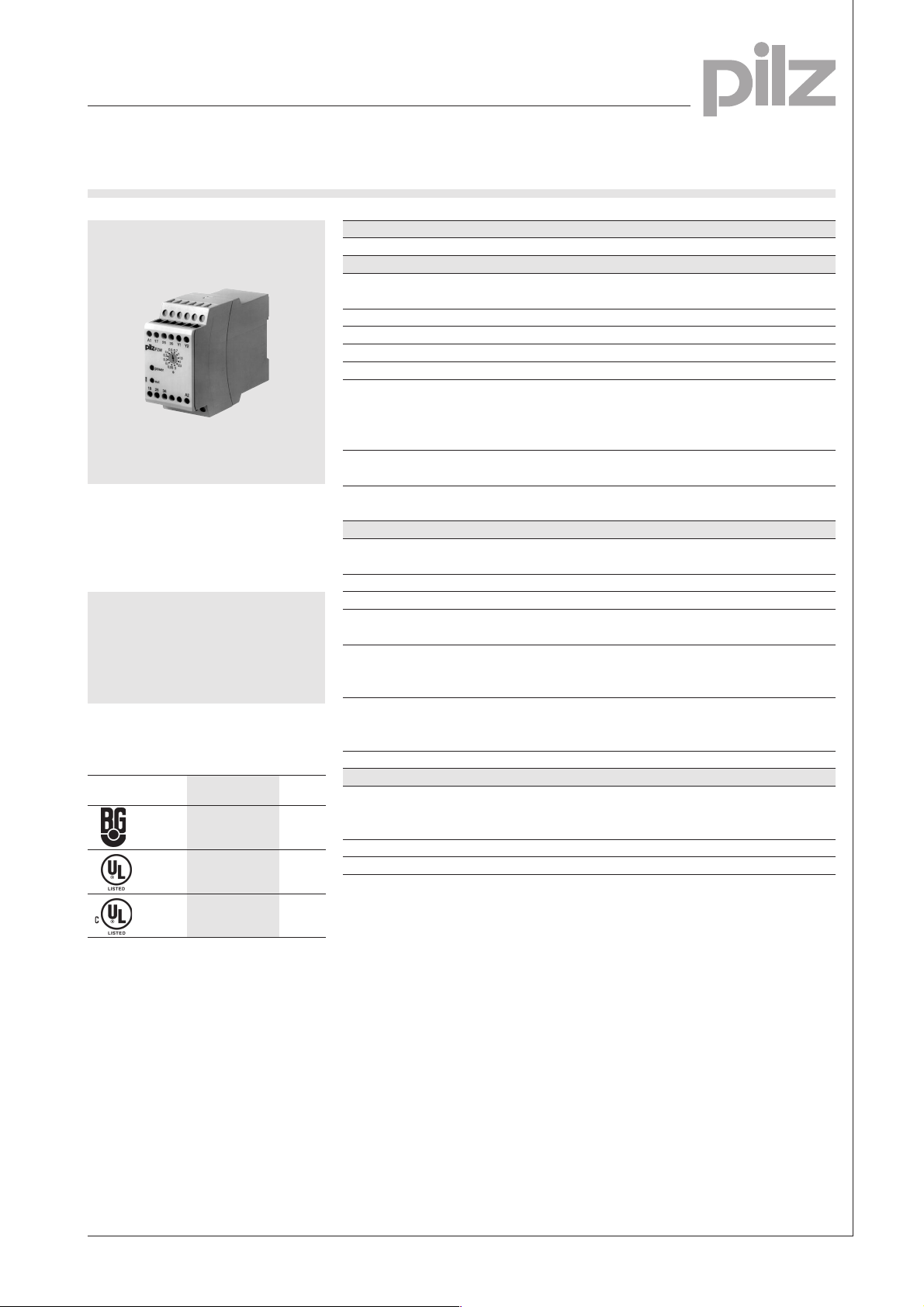
Safe Timer Relays
Limited Inch
PZW
Pulse-on timer relay in accordance
VDE 0113-1, 11/98, EN 60204-1,
12/97, EN 1088, 12/97 and
IEC 204-1, 11/98.
Features
● Self-monitoring time circuits
● Monitoring the inching circuit for
limited movements
Approvals
PZW
●
●
Technical Details PZW
Electrica Data
Supply Voltage AC: 110, 120, 230 V
DC: 24 VDC
Tolerance 85 ... 110 %
Residual Ripple DC 10 %
Power Consumption Approx. 3.5 VA/4 W
Voltage and Current at Y1-Y2 24 VDC, 50 mA
Switching Capability in accordance with
EN 60947-4-1, 10/91 AC1: 240 V/6 A/1500 VA
DC1: 24 V/6 A/150 W
EN 60947-5-1, 10/91 (DC13: 6 cycles/min.) AC15: 230 V/4 A; DC13: 24 V/3A
Output Contacts 1 safety contact (N/O),
2 auxiliary contacts (N/C)
Contact Fuse Protection 6 A quick or 4 A slow
(EN 60947-5-1, 10/91)
Times
Delay-on Energisation AC: Approx. 100 ms
DC: Approx. 50 ms
Delay-on De-energisation Approx. 50 ms
Recovery Time Approx. 80 ms
Time Values 0.05/0.1/0.2/0.3/0.4/0.5/0.7/1.0/1.5/2.0/
2.5/3 s
Setting Accuracy
Start of range 0.05 s ±20 ms
End of range 3.0 s ±60 ms
Time Accuracy
1 % voltage change ±0.06 %
1 °C temperature change ±0.1 %
Repetition Accuracy ±1 %
Mechanical Data
Maximum Cross Section of 1 x 2.5 mm2 or 2 x 1.5 mm
External Conductors Single-core or multi-core with
crimp connectors
Dimensions (H x W x D) 87 x 45 x 121 mm
Weight AC: 350 g, DC: 260 g
2
4
●
Description
● 45 mm, P-93-housing, DIN-Rail
mounting
● Positive-guided relay outputs:
– 1 safety contact (N/O)
– 2 auxiliary contacts (N/C)
● LEDs for power and out
● 12 pulse options, set via
rotary switch
● Increase in the number of
safety contacts available by
connecting expander modules.
Function Description
The PZW provides pulsed cycles
within a safety circuit. It can be
activated by applying the operating
voltage.
The PZW is designed for use with:
● PNOZ safety relays
● PST safety gate monitors
● P2HZ two-hand relays.
NSG-D-2-085-05/01
Safe Timer Relays
Limited Inch
PZW
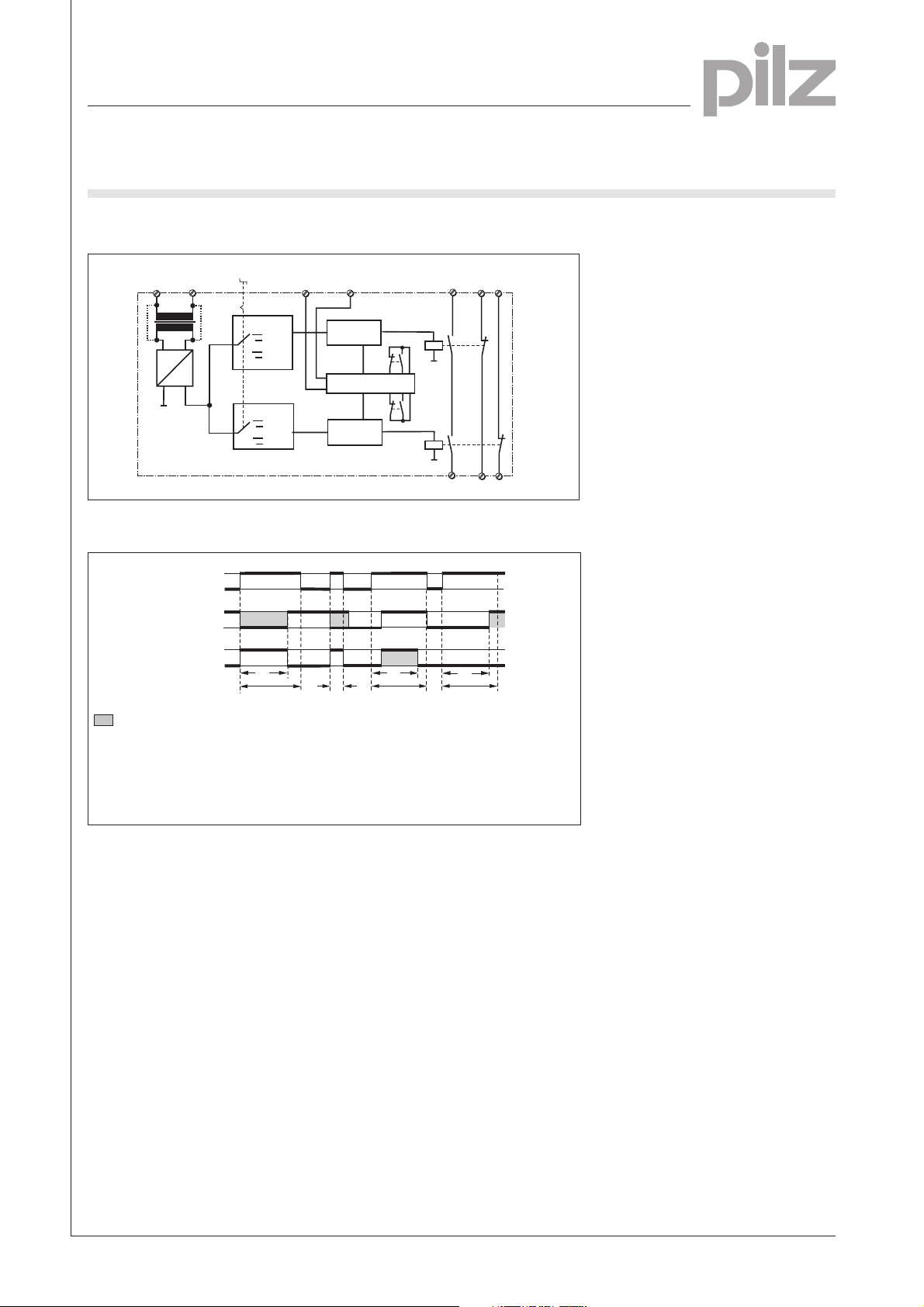
Internal Wiring Diagram
4
Input circuit
A1
A2
U
B
(L+)
~
G1
S1
(L-)
Time
circuit 1
1
...
2
t
W
11
12
=
Time
circuit 2
1
...
2
t
W
11
12
Function Diagram
loop
Output
1
0
1
0
1
0
t
w
(1)
w
Input circuit (UB)
Feedback control
= Undefined time period
(1) = Normal operating cycle
(2) = Fault condition: input circuit
opened too early
(3) = Fault condition: feedback control
loop closed too late within t
Feedback
control loop
Control logic
Control logic
(2)
Auxiliary
Safety
contacts
Y2Y1
K1
Self-test
K2
contact
17
25
K1
K2
18
26
t
w
(3)
t
w
(4)
(4) = Fault condition: feedback
control loop closed too late
after the time t
tw= Inching time
w
35
36
4-2
NSG-D-2-085-05/01

Safe Timer Relays
Limited Inch
PZW
Connection Example
The safety gate monitor PST 1 and
the safety limit switches S4 and S5
monitor safety gates, prohibiting
entry to dangerous machine parts.
The safe pulse action (jog-mode)
provided by the PZW means
movement is limited while the safety
gates are open, i.e. for maintenance
purposes.
1L1
(1L+)
S1
S2
A1
13
S4
PST 1
S5
14 24
1L2
(1L-)
K1 K2
S1: E-STOP button
S2: Switchover key, normal
jog-mode
S3: Enable key
S4/5: Safety gate switch
23 S11 S12
X1 X2
S23
S24
K1
K2
S3
A1
17 25 35
18
K1 K2
A2
26 36 A2
Y1
PZW
Y2
K1
K2
4
Switch operated
Gate open
Gate closed
NSG-D-2-085-05/01

Safe Timer Relays
Limited Inch
PZW
General Technical Data
Unless stated otherwise in the technical details for the specific unit
Electrical Data
Frequency Range AC 50 ... 60 Hz
Residual Ripple DC 160 %
Contact Material AgSnO
Continuous Duty 100 %
Environmental Data
EMC EN 50081-1, 01/92, EN 50082-2, 03/95
Vibration in accordance with Frequency: 10 ... 55 Hz,
EN 60068-2-6, 04/95 Amplitude: 0.35 mm
Climatic Suitability DIN IEC 60068-2-3, 12/86
Airgap Creepage DIN VDE 0110 part 1, 04/97
Ambient Temperature -10 ... +55 °C
Storage Temperature -40 ... +85 °C
Mechanical Data
Torque Setting on Connection Terminals 0.6 Nm (screws)
Mounting Position Any
Housing Material Thermoplast Noryl SE 100
Protection Mounting: IP 54
2
Housing: IP 40
Terminal Range: IP 20
4
The units were tested in accordance with the relevant standards current at
the time of development.
Order References
Type t U
PZW 3 s 24 V DC 774 042
PZW 3 s 110 V AC 774 044
PZW 3 s 120 V AC 774 046
PZW 3 s 230 V AC 774 048
B
Order No.
4-4
NSG-D-2-085-05/01
 Loading...