

Page 1

Nr. 17 987-01
Betriebsanleitung
Technical Instructions
Instruction d'emploi
PNOZ 10
Sicherheitsbestimmungen
• Das Gerät darf nur von Personen
installiert und in Betrieb genommen
werden, die mit dieser Betriebsanleitung
und den geltenden Vorschriften über
Arbeitssicherheit und Unfallverhütung
vertraut sind. Beachten Sie die VDEsowie die örtlichen Vorschriften, insbesondere hinsichtlich Schutzmaßnahmen.
• Beim Transport, bei der Lagerung und im
Betrieb die Bedingungen nach EN 600682-6, 04/95 einhalten (s. technische Daten).
• Durch Öffnen des Gehäuses oder eigenmächtige Umbauten erlischt jegliche Gewährleistung.
• Montieren Sie das Gerät in einen Schaltschrank; Staub und Feuchtigkeit können
sonst zu Beeinträchtigungen der Funktionen führen.
• Sorgen Sie an allen Ausgangskontakten
bei kapazitiven und induktiven Lasten für
eine ausreichende Schutzbeschaltung.
Bestimmungsgemäße Verwendung
Das Sicherheitsschaltgerät PNOZ 10 ist bestimmt für den Einsatz in
• NOT-AUS-Einrichtungen
• Sicherheitsstromkreisen nach VDE 0113
Teil 1, 11/98 und EN 60204-1, 12/97
(z. B. bei beweglichen Verdeckungen)
Safety Regulations
• The unit may only be installed and
operated by personnel who are familiar
with both these instructions and the current
regulations for safety at work and accident
prevention. Follow CEN and local
regulations especially as regards
preventative measures.
• Transport, storage and operating conditions
should all conform to EN 60068-2-6, 04/95
(s. technical data).
• Any guarantee is void following opening of
the housing or unauthorised modifications.
• The unit should be panel mounted, otherwise dampness or dust could lead to
function impairment.
• Adequate protection must be provided on
all output contacts with capacitive and
inductive loads.
Authorised Applications
The Safety Relay PNOZ 10 is for use in:
• Emergency Stop installations.
• Safety Circuits according to VDE 0113
part 1, 11/98 and EN 60204-1, 12/97
(e.g. with movable guards).
Conseils préliminaires
• La mise en oeuvre de l’appareil doit être
effectuée par une personne spécialisée en
installations électriques, en tenant compte
des prescriptions des différentes normes
applicables (NF, EN, VDE...) notamment au
niveau des risques encourus en cas de
défaillance de l’équipement électrique.
• Transport, storage and operating conditions
should all conform to EN 60068-2-6, 04/95
(s. technical data).
• L’ouverture de l’appareil ou sa modifi-cation
annule automatiquement la garantie.
• L’appareil doit être monté dans une armoire; l’humidité et la poussière pouvant
entraîner des aléas de fonctionnement.
• Vérifiez que le pouvoir de coupure des
contacts de sortie est suffisant en cas de
circuits capacitifs ou inductifs.
Domaines d’utilisation
Le bloc logique de sécurité PNOZ 10 est
adapté pour:
• les circuits d’arrêt d’urgence
• les circuits de sécurité selon les normes
NF 79-130 et EN 60-204/1, 12/97 (ex.
protecteurs mobiles).
Gerätebeschreibung
Das Sicherheitsschaltgerät PNOZ 10 ist in
einem P-93-Gehäuse untergebracht. Es
stehen verschiedene Varianten für den
Betrieb mit Wechselspannung und eine
Variante für den Betrieb mit Gleichspannung
zur Verfügung.
Merkmale:
• Relaisausgänge: sechs Sicherheitskontakte (Schließer) und vier Hilfskontakte
(Öffner), zwangsgeführt
• Anschlußmöglichkeit für NOT-AUS-Taster,
Schutztürgrenztaster und Starttaster
• Netzanzeige
• Statusanzeige
• Rückführkreis zur Überwachung externer
Schütze
Das Schaltgerät erfüllt folgende Sicherheitsanforderungen:
• Schaltung ist redundant mit Selbstüberwachung aufgebaut.
• Sicherheitseinrichtung bleibt auch bei
Ausfall eines Bauteils wirksam.
• Bei jedem Ein-Aus-Zyklus der Maschine
wird automatisch überprüft, ob die Relais
der Sicherheitseinrichtung richtig öffnen
und schließen.
• AC- und DC-Schaltgeräte besitzen eine
elektronische Sicherung.
Description
The Safety Relay PNOZ 10 is enclosed in a
P-93 housing. There are different versions
available for AC operation and one for DC
operation.
Features:
• Relay outputs: six safety contacts (N/O)
and four auxiliary contacts (N/C), positiveguided.
• Connections for Emergency Stop Button,
Safety Gate Limit Switch and Reset
Button.
• Power indicator
• Status Indicators.
• Feedback Control Loop for monitoring of
external contactors/relays.
The relay complies with the following safety
requirements:
• The circuit is redundant with built-in selfmonitoring.
• The safety function remains effective in
the case of a component failure.
• The correct opening and closing of the
safety function relays is tested automatically in each on-off cycle.
• AC and DC relays are fitted with an
electronic fuse.
Description de l’appareil
Inséré dans un boîtier P93, le bloc logique
de sécurité PNOZ 10 est disponible en
différentes versions pour les tensions
d’alimentation alternatives et une version en
alimentation continue (24 VDC).
Autres particularités:
• Sorties disponibles: 6 contacts à fermeture de sécurité et 4 contacts à ouverture
pour signalisation
• Bornes de raccordement pour poussoirs
AU, détecteurs de position et poussoir de
validation
• LEDs de visualisation des canaux d’entrée
et de la tension d’alimentation
• Boucle de retour pour l’auto-contrôle des
contacteurs externes
Le relais PNOZ 10 répond aux exigences
suivantes:
• conception redondante avec autosurveillance
• sécurité garantie même en cas de
défaillance d’un composant
• test cyclique (ouverture/fermeture des
relais internes) à chaque cycle Marche/
Arrêt de la machine
• fusible électronique (relais en AC et en
DC)
Page 2
Funktionsbeschreibung
Das Schaltgerät PNOZ 10 dient dem
sicherheitsgerichteten Unterbrechen eines
Sicherheitsstromkreises. Nach Anlegen der
Versorgungsspannung, Brücke zwischen
Y1-Y2 und S12-S34 sowie geöffnetem
Eingangskreis geht Relais K3 in Wirkstellung.
• Eingangskreis geschlossen (z. B. NOTAUS-Taster nicht betätigt)
Relais K1 und K2 gehen über die
Schließer K3.1 und K3.2 in Wirkstellung
und halten sich selbst über K1.1 bzw.
K2.1. Die Statusanzeigen leuchten.
Durch Öffnen der Kontakte K1.2 und
K2.2 geht K3 nach Ablauf der Rückfallverzögerung von 90 ms in Ruhestellung. Die Sicherheitskontakte (13-14/
23-24/33-34/43-44/53-54/63-64) sind geschlossen, die Hilfskontakte (71-72/8182/91-92/01-02) sind geöffnet.
• Eingangskreis wird geöffnet (z. B. NOTAUS-Taster betätigt)
K1 und K2 fallen in die Ruhestellung
zurück. Die Sicherheitskontakte (13-14/
23-24/33-34/43-44/53-54/63-64) werden
redundant geöffnet, die Hilfskontakte (7172/81-82/91-92/01-02) geschlossen.
NOT-AUS-Taster
Emergency Stop Button
Poussoir arrêt d'urgence
Function Description
The relay PNOZ 10 provides a safetyoriented interruption of a safety circuit.
When the operating voltage is supplied, Y1 Y2 and S12 - S34 are bridged and the input
circuit is closed, relay K3 energises.
• Input circuit closed (e.g. Emergency Stop
Button not activated):
Relay K1 and K2 energise via the N/O
K3.1 and K3.2 and latch via K1.1/K2.1.
The status indicators illuminate. By
opening the contacts K1.1 and K2.2, K3
de-energises following the delay-on deenergisation of 90 ms. The safety
contacts (13-14/23-24/33-34/43-44/53-54/
63-64) are closed, the auxiliary contacts
(71-72/81-82/91-92/01-02) are opened.
• Input circuit opened (e.g. Emergency Stop
Button activated):
K1 and K2 de-energise. The safety
contacts (13-14/23-24/33-34/43-44/53-54/
63-64) are opened redundantly, the
auxiliary contacts (71-72/81-82/91-92/01-
02) are closed.
Rückführkreis
Feedback Control Loop
Boucle retour
Sicherheitskontakte, zwangsgeführt
Safety Contacts, positive-guided
Contacts pour circuits de sécurité
Description du fonctionnement
Le relais PNOZ 10 assure de façon sure,
l’ouverture d’un circuit de sécurité. A la mise
sous tension du relais (A1-A2), si Y1-Y2 et
S12-S34 sont pontés et les canaux d’entrée
ouverts, le relais K3 colle.
• Fermeture des canaux d’entrée
(par ex. AU non actionné):
les relais K1 et K2 collent par l’intermédiaire des contacts K3.1 et K3.2 et
s’auto-maintiennent par K1.1 et K2.1. Les
LEDs de visualisation sont allumées.
L’ouverture des contacts K1.2 et K2.2 fait
retomber le relais K3 qui se maintient
environ 90 ms. Les contacts de sortie de
sécurité (13-14/23-24/33-34/43-44/53-54
et 63-64) se ferment, les contacts
d’information 71-72/81-82/91-92 et 01-02
s’ouvrent.
• Ouverture des canaux d’entrée (par ex.
action sur AU):
K1 et K2 retombent. Les contacts de sortie
(13-14/23-24/33-34/43-44/53-54/63-64)
s’ouvrent de façon redondante, les
contacts d’information (71-72/81-82/91-92/
01-02) se ferment.
Hilfsöffner für Sicherheitsstromkreise unzulässig
Auxiliary N/C contacts,
unsuitable for safety circuits
Contact auxilaire ne pas utiliser
dans le circuits de sécurité
U
F1
G1
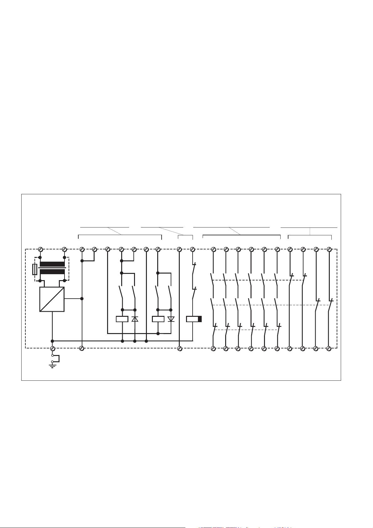
PNOZ 10
B
A2 (L-)A1 (L+)
~
S11 13 23 33 71
+
=
S33
Y3
S11 S21 Y2
S12S12 S22
K3.1 K3.2
K1.1
K1
K2.1
K2
Eintaster, Reset, Poussoir VAL
Fig. 1: Innenschaltbild/Internal Wiring Diagram/Schéma de principe
Betriebsarten:
• Einkanaliger Betrieb: Eingangsbeschaltung nach VDE 0113 und EN 60204-1,
keine Redundanz im Eingangskreis,
Erdschlüsse im Tasterkreis werden
erkannt.
• Zweikanaliger Betrieb: Redundanter Eingangskreis, Erdschlüsse im Tasterkreis
und Querschlüsse zwischen den Tasterkontakten werden erkannt.
• Automatischer Start: Gerät ist aktiv,
sobald Eingangskreis geschlossen.
• Manueller Start: Gerät ist erst dann aktiv,
wenn ein Starttaster betätigt wird.
• Kontaktvervielfachung und -verstärkung
durch Anschluß von externen Schützen.
Operating Modes
• Single-channel operation: Input wiring
according to EN 60204-1, no redundancy in
the input circuit, earth faults are detected in
the emergency stop circuit.
• Two-channel operation: Redundancy in the
input circuit, earth faults in the emergency
stop circuit and shorts across the emergency stop pushbutton will be detected.
• Automatic reset: Unit is active as soon as
the input circuit is closed.
• Manual reset: Unit is only active when a
start button has been pressed.
• Increase in the number of available contacts by connection of external contactors/
relays.
Y1
S34
K1.2
K2.2
K3
4344535463
K1
K2
K3
14 24 34 72
Modes de fonctionnement
• Commande par 1 canal: conforme aux
prescriptions de la EN 60204-1, pas de
redondance dans le circuit d’entrée, la mise
à la terre du circuit d’entrée est détectée.
• Commande par 2 canaux: circuit d’entrée
redondant, la mise à la terre et les courtscircuits entre les contacts sont détectés.
• Réarmement automatique: le relais est
activé dès la fermeture des canaux
d’entrée.
• Réarmement manuel: le relais n’est activé
qu’après une impulsion sur un poussoir de
validation.
• Augmentation du nombre de contacts ou
du pouvoir de coupure par l’utilisation de
contacteurs externes.
818291 01
64
02
92
Page 3

Montage
Das Sicherheitsschaltgerät muß in einen
Schaltschrank mit einer Schutzart von mind
IP 54 eingebaut werden. Zur Befestigung auf
einer Normschiene dient ein Rastelement
auf der Rückseite des Geräts.
Installation
The safety relay must be panel mounted
(min. IP 54). There is a notch on the rear of
the unit for DIN-Rail attachment.
Montage
Le relais doit être monté dans l'armoire ayant
au min. un indice de protection IP 54. Sa face
arrière permet un montage sur rail DIN.
Inbetriebnahme
Beachten Sie bei der Inbetriebnahme:
• Nur die Ausgangskontakte 13-14/23-24/
33-34/43-44/53-54/63-64 sind Sicherheitskontakte. Ausgangskontakte 71-72/81-82/
91-92/01-02 sind Hilfskontakte (z. B. für
Anzeige).
• Vor die Ausgangskontakte eine
Sicherung (10 A flink oder 6 A träge)
schalten, um das Verschweißen der
Kontakte zu verhindern.
• Berechnung der max. Leitungslänge I
im Eingangskreis:
R
lmax
=
I
max
Rl / km
R
= max. Gesamtleitungswiderstand (s.
lmax
technische Daten)
Rl /km = Leitungswiderstand/km
Da die Funktion Querschlußerkennung nicht
einfehlersicher ist, wird sie von Pilz während
der Endkontrolle geprüft. Eine Überprüfung
nach der Installation des Geräts ist wie folgt
möglich:
1. Gerät betriebsbereit (Ausgangskontakte
geschlossen)
2. Die Testklemmen S12/S22 zur Querschlußprüfung kurzschließen.
3. Die Sicherung im Gerät muß auslösen
und die Ausgangskontakte öffnen.
Leitungslängen in der Größenordnung der
Maximallänge können das Auslösen der
Sicherung um bis zu 2 Minuten verzögern.
4. Sicherung wieder zurücksetzen: den
Kurzschluß entfernen und die Versorgungsspannung für ca. 1 Minute abschalten.
• Bei AC-Geräten kann kein zusätzlicher
Verbraucher verwendet werden. Bei DCGeräten zusätzliche Verbraucher mit max.
400 mA.
• Leitungsmaterial aus Kupferdraht mit einer
Temperaturbeständigkeit von 60/75 °C
verwenden.
• Das Anzugsdrehmoment der Schrauben
auf den Anschlußklemmen darf max.
0,6 Nm betragen.
• Angaben im Kapitel „Technische Daten“
unbedingt einhalten.
Ablauf:
• Versorgungsspannung an Klemmen A1 (+)
und A2 (-) anlegen.
- DC: Klemme A2 (-) mit geerdeter Seite
der Versorgungsspannung verbinden.
- AC: Betriebserdungsklemme mit
Schutzleitersystem verbinden.
• Rückführkreis
Brücke an Y1-Y2 oder externe Schütze
anschließen.
• Startkreis
- Automatischer Start:
S12-S34 brücken.
- Manueller Start: Taster an S12-S34
anschließen.
• Eingangskreis
- Einkanalig: S12-Y3 und S21-S22
brücken. Öffnerkontakt von Auslöseelement an S12 und S11 anschließen.
- Zweikanalig: S11-Y3 brücken; Öffner-
max
Operation
Please note for operation:
• Only the output contacts 13-14/23-24/3334/43-44/53-54/63-64 are safety contacts.
Output contacts 71-72/81-82/91-92/01-02
are auxiliary contacts (e.g. for a display).
• To prevent a welding together of the
contacts, a fuse (10 A quick/6 A slow
acting) must be connected before the
output contacts.
• ICalculate the max. cable runs l
input circuit:
R
I
max
R
(see technical details)
lmax
=
Rl / km
= Max. Total cable resistance
lmax
Rl /km = cable resistance/km
As the function for detecting shorts across
the inputs is not failsafe, it is tested by Pilz
during the final control check. However, a
test is possible after installing the unit and
it can be carried out as follows:
1. Unit ready for operation (output contacts
closed)
2. Short circuit the test (connection) terminals
S12/S22 for detecting shorts across the inputs
3. The unit‘s fuse must be triggered and
the output contacts must open. Cable
lengths in the scale of the maximum
length can delay the fuse triggering for up to
2 minutes.
4. Reset the fuse: remove the short circuit
and switch off the operating voltage for
approx. 1 minute.
• When your external device (limit switch
etc.) has a current consumption, with DC
units this must not exceed 400 mA. With
AC units no load is permitted.
• Use copper wire that will withstand
60/75 °C
• Tighten terminals to 0.6 Nm.
• Important details in the section „Technical
Data“ should be noted and adhered to.
To operate:
• Supply operating voltage to terminals A1
(+) and A2 (-).
- DC: Connect terminal A2 (-) with the
earthed side of the operating voltage.
- AC: Connect the operating earth
terminal with the ground earth.
• Feedback control loop
Bridge Y1 - Y2 or connect external
contactors/relays.
• Reset circuit
- Automatic reset: Bridge S12 - S34.
- Manual reset: Connect button on
S12 - S34.
• Input circuit
- Single-channel: Bridge S12 - Y3 &
S21 - S22. Connect N/C contact from
trigger element (e.g. E-Stop) to S12
and S11.
- Two-channel: Bridge S11 -Y3. Connect
N/C contact from trigger element (e.g.
E-Stop) to S11 - S12/S21 - S22.
The safety contacts are activated (closed)
and the auxiliary contacts (71-72/81-82/9192/01-02) are open. The status indicators
max
in the
Mise en oeuvre
Remarques préliminaires:
• Seuls les contacts 13-14, 23-24, 33-34,
43-44, 53-54, 63-64 sont des contacts de
sécurité. Les contacts 71-72, 81-82, 9192, 01-02 sont des contacts d’information
(ex. voyant).
• Protection de contacts de sortie par
des fusibles 10 A rapides ou 6 A
normaux pour éviter leur soudage.
• Calcular les longueurs de câblage max
I
dans le circuit d’entrée:
max
R
I
max
R
max.(voir les caractéristiques techniques)
Rl /km = résistivité de câblage/km
La fonction de détection de court-circuit est
testé par Pilz lors du contrôle final. Un test
sur site est possible de la façon suivante:
1. Appareil en fonction (contacts de sortie
fermés)
2. Court-circuiter les bornes de
raccordement nécessaires au test S12/S22
3. Le fusible interne du relais doit déclencher
et les contacts de sortie doivent s‘ouvrir.
Le temps de réponse du fuisible peut aller
jusqu‘à 2 min. si les longueurs de câblage
sont proches des valeurs maximales.
4. Réarmement du fusible: enlever le
court-circuit et couper l‘alimentation du
relais pendant au moins 1 min.
• Pour les relais AC, aucun autre utilisateur
ne peut être alimenté. Pour les relais en
DC, utilisateur suppl. possible jusqu’à 400
mA max.
• Utiliser uniquement des fils de cablâge en
cuivre 60/75 °C.
• Le couple de serrage sur les bornes de
racordement ne doît pas dépasser
0,6 Nm.
• Respecter les données indiquées dans le
chap. „Caractéristiques techniques“.
Mise en oeuvre:
• Amener la tension d’alimentation sur A1
et A2
- DC: borne A2 à relier au „-“
- AC: relier la borne terre
• Boucle de retour
Pontage de Y1-Y2 ou branchement des
contacts externes
• Circuit de réarmement
- Réarmement automatique: pontage des
- Réarmement manuel: câblage d’un
• Circuits d’entrée
- Commande par 1 canal: câblage du
- Commande par 2 canaux: câblage des
Les contacts de sortie se ferment et les
contacts d’information (71-72/81-82/91-92/
01-02) s’ouvrent. Les LEDs de visualisation
des canaux 1 et 2 sont allumées. L’appareil
est prêt à fonctionner.
lmax
=
Rl / km
= résistivité de câblage totale
lmax
bornes S12-S34
poussoir sur S12-S34
contact à ouverture entre S11 et S12,
pontage de S21-S22 et S12-Y3
contacts à ouverture entre S11-S12/
S21-S22 , pontage de S11-Y3
Page 4

S11 S11
S12 Y2
S34
Y3
S21
S22
S12 Y1
S1
S3
kontakt von Auslöseelement an S11-
S12/S21-S22 anschließen.
Die Sicherheitskontakte sind aktiviert
(geschlossen) und die Hilfskontakte (71-72/
81-82/91-92/01-02) sind geöffnet. Die
Statusanzeigen von Kanal 1 und Kanal 2
leuchten. Das Gerät ist betriebsbereit.
Wird der Eingangskreis geöffnet, öffnen
die Sicherheitskontakte 13-14/23-24/33-34/
43-44/53-54/63-64 und die Hilfskontakte
71-72/81-82/91-92/01-02 schließen. Die
Statusanzeige erlischt.
Wieder aktivieren:
• Eingangskreis schließen.
• Bei manuellem Start zusätzlich Taster
zwischen S12 und S34 betätigen.
Die Statusanzeigen leuchten wieder, der
Eingangskreis ist aktiviert.
from channel 1 and channel 2 are
illuminated. The unit is ready for operation.
If the input circuit is opened, the safety
contacts 13-14/23-24/33-34/43-44/53-54/6364 open and the auxiliary contacts 71-72/8182/91-92/01-02 close. The status indicator
goes out.
Reactivation:
• Close the input circuit.
• With manual reset, the button between
S12-S34 must also be pressed.
The status indicators illuminate once more,
the input circuit is activated.
Si le circuit d’entrée est ouvert, les contacts
de sortie 13-14/23-24/33-34/43-44/53-54/6364 s’ouvrent et les contacts d’information 7172/81-82/91-92/01-02 se ferment. Les LEDs
s’éteignent.
Remise en route:
• fermer le(s) circuit(s) d’entrée
• en cas de réarmement manuel, appuyer
sur le poussoir de validation S12-S34
Les LEDs sont à nouveau allumées. Les
contacts de sortie sont fermées.
S11 S21 S12
S1
S12
Y3
S12
S3
Y1
Y2
S34S22
Fig. 1: Eingangskreis einkanalig/Singlechannel input circuit/Commande par 1 canal
S11
S12
S21
S1
S3
S22
S12 Y1
S34
Y2
Y3
S12
Fig. 4: Schutztürsteuerung einkanalig/Single
channel safety gate control/Surveillance de
protecteur, commande par 1 canal
S11 S21
S1
S3
S22
S12 Y2
S12 Y1
S34
Y3
S11
Fig. 2: Eingangskreis zweikanalig/Twochannel input circuit/Commande par 2
canaux
Y3
S2
S1
S12
S21
S12 Y1
S3
S34
Y2
S11
S11
S22
Fig. 5: Schutztürsteuerung zweikanalig/Two
channel safety gate control/Surveillance de
protecteur, Commande par 2 canaux
Fig. 3: Eingangskreis zweikanalig ohne
Querschlußerkennung/Two-channel input
circuit; no short-circuit recognition/
Commande par 2 canaux sans détection des
c. c.
S12
S34
Fig. 6: Automatischer Start/Automatic reset/
Rearmement automatique
Fig. 7: Manueller Start/Manual reset/
Rearmement manuel
S3
S12
S34
1L1
K5
K4
Y1 Y2
1L2
13
14
K4 K5
Fig. 8: Anschlußbeispiel für externe Schütze/
Connection example for external contactors,
relays/Branchement contacteurs externes
betätigtes Element/Switch
activated/élément actionné
Tür nicht geschlossen/Gate
open/porte ouverte
Tür geschlossen/Gate closed/
porte fermée
S1/S2: NOT-AUS- bzw. Schutztürschalter/
Emergency Stop Button, Safety Gate
Limit Switch/Poussoir AU, détecteurs
de position
S3: Starttaster/Reset button/Poussoir de
réarmement
Page 5

Fehler - Störungen
• Erdschluß bei PNOZ 10: Eine elektronische Sicherung bewirkt das Öffnen der
Ausgangskontakte bei Fehlströmen
>1,2 A. Nach Wegfall der Störungsursache und Abschalten der Versorgungsspannung für ca. 1 Minute ist das Gerät
wieder betriebsbereit.
• Fehlfunktionen der Kontakte: Bei verschweißten Kontakten ist nach Öffnen des
Eingangskreises keine neue Aktivierung
möglich.
• Nur eine oder keine Leuchtdiode leuchtet:
Externer Beschaltungsfehler oder interner
Fehler liegt vor.
Faults/Disturbances
• Earth fault on PNOZ 10: An electronic fuse
causes the output contacts to open with
fault currents >1.2 A. Once the cause of
the fault has been removed and operating
voltage is switched off, the unit will be
ready for operation after approximately 1
minute.
• Faulty contact functions: In the case of
welded contacts, no further activation is
possible following an opening of the input
circuit.
• Only one or no LED illuminates: An
external wiring fault or an internal fault is
present.
Erreurs-Défaillances
• Défaut de masse du PNOZ 10: un fusible
électronique entraîne l’ouverture des
contacts de sortie si l’intensité est
> à 1,2 A. L’appareil est à nouveau prêt à
fonctionner après environ 1 minute.
• Défaut de fonctionnement des contacts
internes: en cas de soudage d’un contact
lors de l’ouverture du circuit d’entrée, un
nouvel réarmement est impossible.
• Seule une ou pas de LED est allumée:
erreur de câblage externe ou défaut
interne du boîtier
Technische Daten/Technical Data/Caractéristiques techniques
Versorgungsspannung UB/Operating Voltage UB/Tension d’alimentation U
Spannungstoleranz UB/Voltage Tolerance UB/Plage de la tension d’alimentation U
Leistungsaufnahme bei UB/Power Consumption/Consommation pour U
B
B
B
Frequenzbereich/Frequency Range/Fréquence AC: 50 ... 60 Hz
Restwelligkeit/Residual Ripple/Ondulation résiduelle DC: 160 %
Ausgangskontakte nach EN 954-1, 07/96, Kategorie 4 6 Sicherheitskontakte (S)/4 Hilfskontakte (Ö)
Output Contacts to EN 954-1, 07/96, category 4 6 Safety Contacts (N/O), 4 Auxiliary
Contacts de sortie d'après EN 954-1, 07/96, catégorie 4 6 F de sécurité + 4 O d'information
Kontaktmaterial/Contact material/Matériau contact AgSnO
Einschaltverzögerung/Switch-on delay/Temps d’enclenchement ca./appx./env. 150 ms
Rückfallverzögerung K3/Delay-on De-Energisation K3/Temps de retombée de K3 ca./appx./env. 90 ms
Rückfallverzögerung/Delay-on De-Energisation/Temps de retombée < 50 ms
Gleichzeitigkeit/Simultaneity/Désynchronisme S11-S12, S12-S22 ca./appx./env. 90 ms
Gebrauchskategorie nach/Utilization category to/Catégorie d'utilisation d'après
EN 60947-4-1, 10/91 AC1: 240 V/0,03 ... 8 A/2000 VA
EN 60947-5-1, 1997 (DC13: 6 Schaltspiele/Min, 6 cycles/min, 6 manoeuvres/min) AC15: 230 V/5 A; DC13: 24 V/7 A
Spannung und Strom an/Voltage and Current at/Tension et courant à 24 V DC, 50 mA
S11, S12, S21, S22, S33, S34, Y1, Y2
Umgebungstemperatur/Operating Temperature/Température d’utilisation -10 ... + 55 °C
Lagertemperatur/Storage Temperature/Température de stockage -40 ... +85 °C
Klimabeanspruchung/Climate Suitability/Conditions climatiques DIN IEC 60068-2-3, 12/86
Luft- und Kriechstrecken/Airgap Creepage/Cheminement et claquage DIN VDE 0110 Teil/part/Partie 1, 04/97
Kontaktabsicherung extern nach/External Contact Fuse Protection/Protection des contacts 10 A flink/quick acting/rapide oder/or/ou
de sortie EN 60947-5-1, 1997 6 A träge/slow acting/normal
Max. Gesamteitungswiderstand R
R
per channel (input circuit)/résistivité de câblage totale max. R
lmax
einkanalig/single-channel/Commande par 1 canal 60
pro Kanal (Eingangskreis)/Max. total cable resistance
lmax
par canal(Circuits d’entrée)
lmax
zweikanalig ohne Querschlußerkennung/dual-channel without detection of shorts across
the input contacts/command par 2 canaux sans détection des courts-circuit 120
zweikanalig mit Querschlußerkennung/dual-channel with detection of shorts across the
input contacts/command par 2 canaux avec détection des courts-circuit 20
EMV/EMC/CEM
Schwingungen nach/Vibrations to/Vibrations d'après EN 60068-2-6, 04/95 Frequenz/Frequency/Frequence: 10 ... 55 Hz
Einbaulage/Fitting Position/Position de travail beliebig; any; indifférente
Schutzart/Protection/Indice de protection
Einbauraum/Min. mounting (eg. panel)/Lieu d'implantation (ex. armoire) IP 54
Gehäuse/Housing/Boîtier IP 40
Klemmenbereich/Terminals/Bornes IP 20
Max.Querschnitt des Außenleiters Einzelleiter oder mehrdrähtiger Leiter mit
Max. cable cross section Adernendhülse/single-core or multicore
Raccordement with crimp connectors/fils séparés ou fils
Anzugsdrehmoment für Anschlußklemmen (Schrauben)/Torque setting for connection 0,6 Nm
terminal screw/couple de serrage (bornier)
Gehäusematerial/Housing material/Matériau boîtier Kunststoff/Plastic/Plastique
Abmessungen H x B x T/Dimensions H x W x D/Dimensions H x P x L 87 x 90 x 121 mm (3.42" x 3.54" x 4.76")
Gewicht/Weight/Poids AC: 920 g, DC: 750 g
AC: 24, 42, 48, 110-120, 230-240 V
DC: 24 V
85 ... 110 %
10 VA/4,5 W
Contacts (N/C)
2
400 V/0,03 ... 5 A/2000 VA
DC1: 24 V/0,03 ... 8 A/200 W
W
W
W
EN 50082-1, 08/97, EN 50081-1, 01/92
Amplitude/Amplitude/Amplitude: 0,35 mm
groupés avec embout:
2 x 1,5 mm2 oder/or/ou 1 x 2,5 mm
2
Thermoplast Noryl SE 100
Page 6

Lebensdauer der Ausgangsrelais/Service Life of Output relays/Durée de vie des relais de sortie
Lebensdauerkurven und Schaltvermšgen mit S-Kontakten
100
DC13: 24V
ermittelt nach DIN EN 60947-5-1 Tabelle C2
AC1: 400V
AC15: 230V
AC15: 400V
DC1: 24V
AC1: 230V
AC1: 400V
AC15: 230V
AC15: 400V
DC13: 24V
DC1: 24V
10
Nennbetriebsstrom x 0,1 A
Nennbetriebsstrom x 0,1 A
Nominal operating current x 0,1 A
Courant coupé x 0,1 A
1
10 100 1000 10000
Schaltspielzahl x 10
Cycles x 10
Nombre de manœvres x 10
3
3
Abmessungen in mm (")/Dimensions in mm (")/Dimensions en mm (")
121 (4.76")
AC1: 230V
3
75 (2.95")
90 (3.54")
87 (3.42")
Max. Schaltstrom bei gleichzeitiger Belastung mehrerer Kontakte/Total current switching capability across
all contacts/Intensité commutée max. en cas de charge sur plusieurs contacts (AC1, DC1)
Anzahl der Kontakte/number of contacts/nombre des contacts 6 5 4321
Imax (A) bei Versorgungsspannung AC/with operating voltage AC/
pour tension d’alimentation AC 4 4,4 4,9 5,6 7 8
Imax (A) bei Versorgungsspannung DC/with operating voltage DC/
pour tension d’alimentation DC 5 5,4 6,1 7 8 8
Um ein Versagen der Geräte zu verhindern,
an allen Ausgangskontakten für eine ausreichende Funkenlöschung sorgen. Bei
kapazitiven Lasten sind eventuell auftretende
Stromspitzen zu beachten. Bei DC-Schützen
Freilaufdioden zur Funkenlöschung einsetzen,
um die Lebendauer der Schütze zu erhöhen.
A
Pilz Ges.m.b.H., ✆ 01 7986263-0, Fax: 01 7986264, E-Mail: pilz@pilz.at
95446311, E-Mail: safety@pilz.com.au
Industriais Ltda.,
E-Mail: pilz@pilz.ch
938497544, E-Mail: pilz@pilz.es
✆ 11 4337-1241, Fax: 11 4337-1242, E-Mail: pilz@pilzbr.com.br
DK
Pilz Skandinavien K/S, ✆ 74436332, Fax: 74436342, E-Mail: pilz@pilz.dk
B L
F
Pilz France Electronic, ✆ 03 88104000, Fax: 03 88108000, E-Mail: siege@pilz-france.fr
✆ 09 27093700, Fax: 09 27093709, E-Mail: pilz.fi@pilz.dk
I
Pilz ltalia Srl, ✆ 031 789511, Fax: 031 789555, E-Mail: info@pilz.it
sales@pilz.ie
Fax: 55 5572 4194, E-Mail: info@mx.pilz.com
6345350, Fax: 09-6345350, E-Mail: t.catterson@pilz.co.nz
China Representative Office,
E-Mail: info@pilzkorea.co.kr
Hizmetleri Tic. Ltd. ¸Sti.,
E-Mail: info@pilzusa.com
www
D
E-Mail: pilz.gmbh@pilz.de
J
Pilz Japan Co., Ltd., ✆ 045 471-2281, Fax: 045 471-2283, E-Mail: pilz@pilz.co.jp
NL
✆ 021 62493031, Fax: 021 62493036,
SE
✆ 0224 2360180, Fax: 0224 2360184, E-Mail: pilz.tr@pilz.de
www.pilz.com
Pilz GmbH & Co. KG, Sichere Automation, Felix-Wankel-Straße 2, 73760 Ostfildern, Deutschland, ✆ +49 711 3409-0, Fax: +49 711 3409-133,
Pilz Skandinavien K/S, ✆ 0300 13990, Fax: 0300 30740, E-Mail: pilz.se@pilz.dk
To prevent failure of the unit, all output
contacts should be fused adequately. With
capacative loads, possible current peaks are
to be avoided. With DC contactors/relays
use suitable spark suppression to ensure
extended life of the contactors/relays.
AUS
Pilz Belgium, ✆ 09 3217570, Fax: 09 3217571, E-Mail: info@pilz.be
Pilz Australia Industrial Automation LP., ✆ 03 95446300, Fax: 03
CH
Pilz lndustrieelektronik GmbH, ✆ 062 88979-30, Fax: 062 88979-40,
E
GB
Pilz Automation Technology, ✆ 01536 460766, Fax: 01536 460866, E-Mail: sales@pilz.co.uk
IRL
Pilz Ireland Industrial Automation, ✆ 021 4346535, Fax: 021 4804994, E-Mail:
MEX
Pilz Nederland, ✆ 0347 320477, Fax: 0347 320485, E-Mail: info@pilz.nl
P
Pilz Industrieelektronik S.L., ✆ 229407594, Fax: 229407595, E-Mail: pilz@pilz.es
E-Mail: sales@pilz.com.cn
USA
ROK
Pilz Automation Safety L.P., ✆ 734 354-0272, Fax: 734 354-3355,
Prévoir un dispositif d’extinction d’arc sur les
contacts de sortie pour éviter un éventuel
disfonctionnement du relais.
Tenir compte des pointes d’intensité en cas
de charge capacitive. Equiper les
contacteurs DC de diodes de roue libre .
Pilz lndustrieelektronik S.L., ✆ 938497433, Fax:
Pilz de Mexico, S. de R.L. de C.V., ✆ 55 5572 1300,
Pilz Korea Office, ✆ 031 8159541, Fax: 031 8159542,
BR
Pilz do Brasil Sistemas Eletrônicos
FIN
Pilz Skandinavien K/S,
NZ
Pilz New Zealand, ✆ 09-
TR
Pilz Elektronik Güvenlik Ürünleri ve
PRC
Pilz
17 987-01-09/03 Printed in Germany
 Loading...