

Philips FWD-185 Service Manual

DVD Mini-HiFi System
S
e
r
v
ice
S
e
r
v
ice
FWD185
/ 79 / 94 / 98
Tfswjdf
Tfswjdf
Service
Service Manual
TABLE OF CONTENTS
Service news letter .............................................1-1...1-4
Location of PC
Versions Variation & Package .
Specification
Repair Instruct
Disassembly Instructions &
Block & Wiring Diagram ................................................ 4
Control Board ................................................................. 5
Main Boar
Power Boar
Mechanical Exploded View & Parts.............................. 9
Service partlist..............................................................10
F actory partlist..............................................................11
©
Copyright 2007 Philips Consumer Electronics B.V. Eindhoven, The Netherlands
All rights reserved. No part of this publication may be reproduced, stored in a retrieval system or
transmitted, in any form or by any means, electronic, mechanical, photocopying, or otherwise
without the prior permission of Philips.
Published 0842 by DB Service Audio Printed in The Netherlands Subject to modification
Version 1.3
Boards
s .........................
ions .................
d ..................................................................... 6
d .................................................................. 7
................................................1-5
...................................1-5
.....................................
........................................ 2
Service positi
Page
1-6
ons .............. 3
!
3141 785 31873

Service Newsletter 2002 – BCU Audio 1/4
For internal use only PHILIPS
ISSUE SNL2002.09 (02-12-06)
Published by:
Service Depar tment Audio
BUSINESS CREATION UNIT AUDIO
General Information
This special edition contains instructions on CD-applications with playability problems (i.e.
skipping tracks).The information shows how to check the playability of the set, how to
clean the lens, and how to measure if some important drive parameters like jitter, laser
current and offset values are (still) within the specification.
Background for this information are extensive analyses on replaced CD-drives. It has
been found that a lot of replaced drives were not defective at all, respectively were
replaced for the wrong reason.We are convinced that the procedures on the next pages
will help to reduce the number of erroneously replaced drives drastically and request you
to deploy the instructions to the workshops urgently.
SERVICE NEWSLETTER
1-1
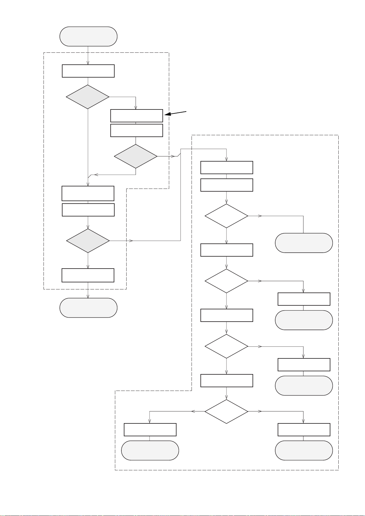
Service Newsletter 2002 – BCU Audio 2/4
Set remains closed!
Standard repair procedure
N
Y
Play a CD
for at least 10 minutes
Y
playability
ok ?
N
playability
ok ?
add Info for customer
"SET OK"
playability
ok ?
Y
N
check playability
N
Y
playability
ok ?
check playability
check playability
EYE-Pattern
ok ?
N
Y
check "EYE-Pattern"
replace CD Drive
Laser current
ok ?
N
Y
check Laser current
CD Drive offsets
ok ?
N
Y
check CD Drive offsets
clean the lens
check playability
return set
Customer complaint
"CD related problem"
return set
return set
replace CD Drive
return set
replace CD Drive
return set
replace Signal Processor
return set
"fast" lens cleaning
1
2
3
4
5
6
7
For flap loaders (= access to CD drive possible)
cleaning method
4
is recommended
1
-
7
For description - see following pages
1-2
Service Newsletter 2002 – BCU Audio 3/4
1
PLAYABILITY CHECK
For sets which are compatible with CD-RW discs
use CD-RW Printed Audio Disc....................7104 099 96611
TR 3 (Fingerprint)
TR 8 (600µ Black dot)
maximum at 01:00
• playback of these two tracks without audible disturbance
playing time for: Fingerprint
≥
10seconds
Black dot from 00:50 to 01:10
• jump forward/backward (search) within a reasonable time
For all other sets
use CD-DA SBC 444A..................................4822 397 30245
TR 14 (600µ Black dot)
maximum at 01:15
TR 19 (Fingerprint)
TR 10 (1000µ wedge)
• playback of all these tracks without audible disturbance
playing time for: 1000µ wedge
≥
10seconds
Fingerprint
≥
10seconds
Black dot from 01:05 to 01:25
• jump forward/backward (search) within a reasonable time
2
CUSTOMER INFORMATION
It is proposed to add an addendum sheet to the set which
informs the customer that the set has been checked
carefully - but no fault was found.
The problem was obviously caused by a scratched, dirty or
copy-protected CD. In case problems remain, the customer
is requested to contact the workshop directly.
The lens cleaning (method 3) should be mentioned in the
addendum sheet.
The final wording in national language as well as the printing
is under responsibility of the Regional Service Organizations.
3
FAST LENS CLEANING (dry brush)
Use lens cleaning CD
SBC AC300...........................................9082 100 00043
Insert the lens cleaning CD, press PLAY and follow the
voice guide´s instructions on the CD.
4
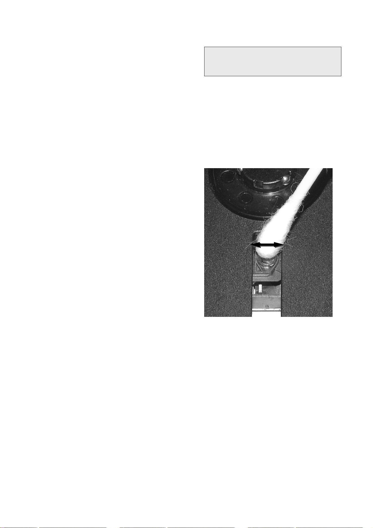
LIQUID LENS CLEANING
Because the material of the lens is synthetic and coated
with a special anti-reflectivity layer, cleaning must be done
with a non-aggressive cleaning fluid. It is advised to use
“Cleaning Solvent B4-No2”, available with codenumber
4822 389 10026.
The actuator is a very precise mechanical component and
may not be damaged in order to guarantee its full function.
Clean the lens gently (don’t press too hard) with a soft and
clean cotton bud moistened with the special lens cleaner.
The direction of cleaning must be in the way as indicated in
the picture below.
Before touching the lens it is advised to clean the
surface of the lens by blowing clean air over it.
This to avoid that little particles make scratches on
the lens.
1-3
Service Newsletter 2002 – BCU Audio 4/4
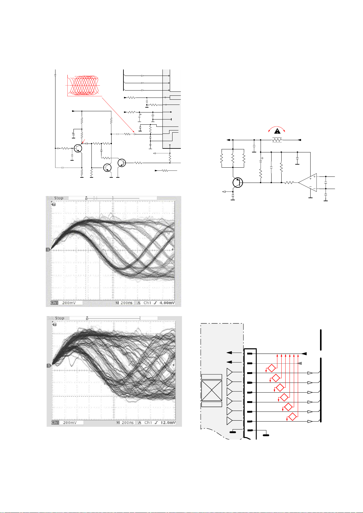
5
EYE-PATTERN SIGNAL – JITTER MEASUREMENT
Measure the signal on the input of the Signal processor
using an analog oscilloscope. Please find the exact
measuring point in your Service Manual.
See below examples of the signal. Amplitude should read at
least 700mVpp using SBC444A.
good
bad
If the oscilloscope shows a signal like the ‘bad’ one, and/or
the amplitude decreases within 1 minute - the CD drive has
to be replaced.
6
CD DRIVE – LASER CURRENT MEASUREMENT
The laser current can be measured as a voltage drop on a
resistor. The resistor is marked in every Service Manual.
The value depends on the type of CD drive.
typical value most probably defect
VAMxxxx : 150-230mV ≥350mV
MCDxx : 170-230mV ≥300mV
DA1x : 210-250mV ≥350mV
DA2x : 175-200mV ≥250mV
Use SBC444A (CD-DA) for measurement.
7
CD DRIVE – OFFSET MEASUREMENT
The photodiodes of the CD-drive may have an offset. These
offsets have to be compensated by the signal processor.
High offsets can lead to poor playability of some CDs
(skipping tracks).
To measure the offset values, start the
Service Test
Program
- section “Focus Test” without a CD.
The offsets can be measured with a DC Millivoltmeter
directly on the connector (see drawing below). Pin
numbering varies from drive to drive.
The values from diode A-D should read 0±10mV.
Diodes E and F are less critical.
If one of the offsets is higher than ±10mV the CD drive has
to be replaced. Otherwise replace the Signal Processor.
Sanyo DA12T3
CD Drive
A
A
F
C
B
E
C
D
E
VCC
B
VREF
F
D
9
10
11
12
13
14
15
16
1800
+5V_HF
VrefCD10
A
D
E
B
C
F
GND
8
E
D
A
B
C
F
Laser power control
100n
2878
470n
2876
3821
1R
1K
3823
2880
33p
+5V
BC807-40
7879
3817
47R
3820
4R7
47R
3819
1n
2879
2877
47u
1
8
4
7811-A
LM358D
3
2
10K
3822
47R
3818
2841
100n
47n
2869
+5V_HF
LASER DIODE
U >250mV
->Laser damaged !
4,6V
3V
3,3V
3,9V
2V
0,17V
0,17V
Sanyo
DA12T3
HF-Amplifier
D3
D2
D1
680R
3905
3903
3K3
BC847B
7877
47n
2818
1K5
3902
5
7
4
2
1
6
3
64
8
9
10
11
470R
3893
+3.3V
2K2
3908
10K
3923
BC847B
7878
BC847B
7876
4n7
2813
3896
100R
220u
2885
2881
560p
47n
2887
560R
3901
2883
470n
2817
4u7
3n3
2814
3898
220R
3895
27K
470n
2884
+3.3V
3909
820R
3907
100R
3920
33K
3897
2882
82p
3K3
3904
2K7
3899
3906
470R
+5V_HF
HFIN
VrefCD10
100p
2815
2816
22n
LDON
to 3826,3827
VREF GE
VDDA1
VRIN
VSSA1
ISLICE
LD
ON
D1
D2
D3
D4
HFIN
HFREF
IREF
CD_DA: 0V / CD_RW: 3V
Σ
(A-D)
800mVpp
TB = 0.5
µ
s/div
EYE-PATTERN
1,8V
1,2V
2,4V
2,6V
0,65V
1-4
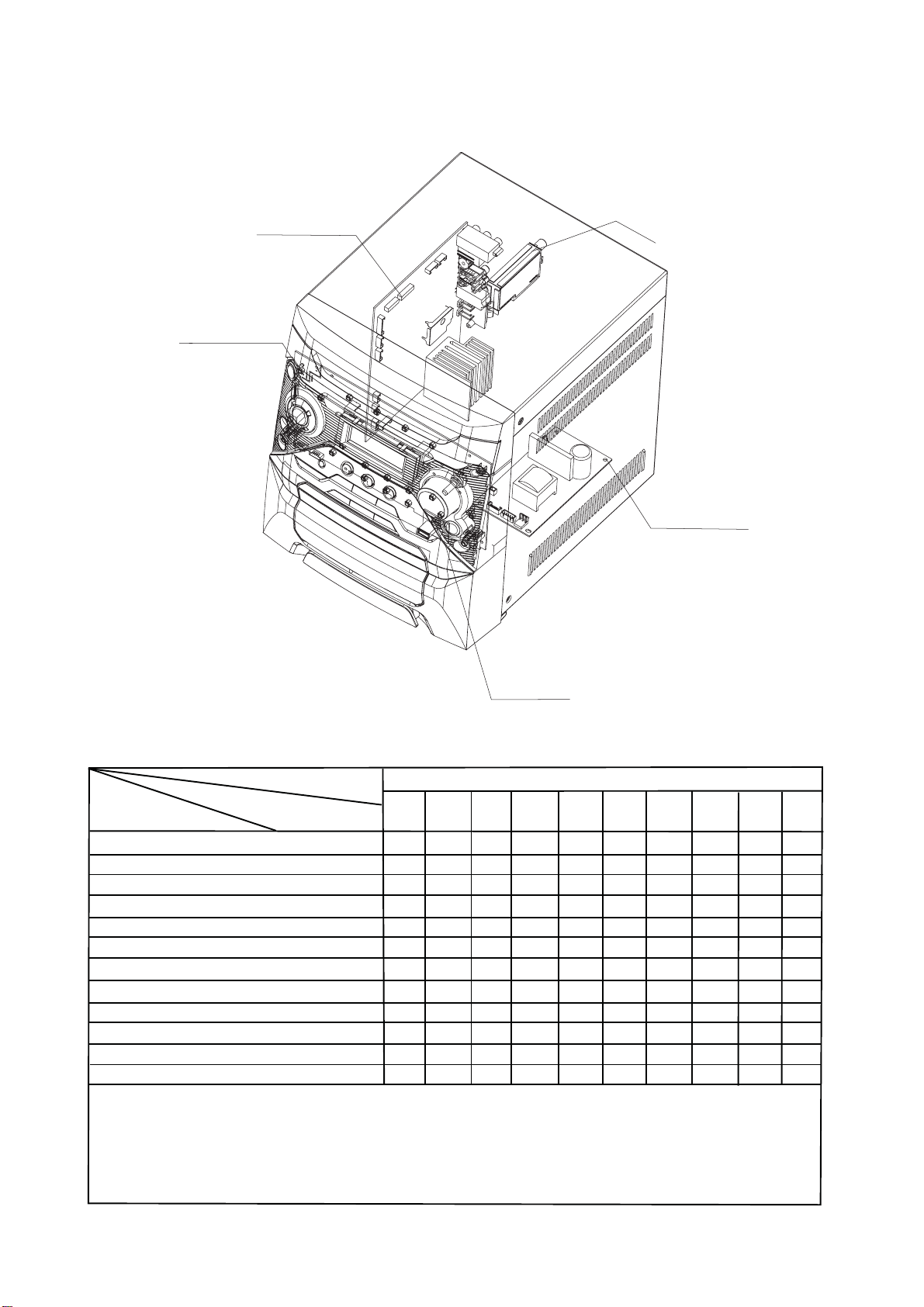
LOCATION OF PCB BOARDS
√
1-5
CONTROL CPB
MAIN PCB
TUNER
POWER PCB
VERSION VARIATIONS:
Type /Versions:
Features &
Board in used:
MAIN BOARD
TUNER BOARD
CONTROL BOARD
POWER BOARD
USB BOARD
* TIPS : C -- Component Lever Repair.
M -- Module Lever Repair
Service policy&
-- Used
Feature diffrence
USB PCB
FWD185
/79
C
M
C
C
C
/94
C
M
C
C
C
/98
C
M
C
C
C

SPECIFICATION
1-6
AMPLIFIER SECTION
Output power .................................................... 1800 W PMPO
Stereo mode ....................................................... 2 x 50 W RMS
Frequency Response .......................... 50 Hz - 18 kHz / ± 3 dB
Signal-to-Noise Ratio
Input Sensitivity
AUX In ................................................................ ......... 600 mV
Output Sensitivity
Headphone ............................................................25 mV + 1dB
Line Out ..................................................... (CD mode)2 + 0.2 V
TUNER SECTION
Tuning Range ...........................................................................
.......................................... FM 87.5 – 108 MHz ( 50 kHz steps)
............................................ MW 531 – 1602 kHz (9 kHz steps)
...........................................MW 530 – 1700 kHz (10 kHz steps)
Signal-to-Noise Ratio ...............................
............................................................................... MW ≥ 35 dB
TAPE SECTION
Frequency Response
Normal tape ............... ......................... 80 – 12500 Hz ( +8 dB)
Signal-to-Noise Ratio
Normal tape ................................................ ............... ≥ 45 dBA
JIS and WTD ................................................................. ≤ 0.3%
DVD SECTION
Laser Type ................................................ ....... Semiconductor
Disc Diameter .............................................. .......... 12cm / 8cm
Video Decoding ........................................ MPEG-2 / MPEG-1/
Divx 3/4/5/6, Ultra
Video DAC ................................................................ .... 12 Bits
Signal System ...............................................
Video Format ..................................................... ....... 4:3 / 16:9
Video S/N ...................................................... 56 dB (minimum)
Composite Video Output .................................. 1.0 Vp-p, 75 Ω
S-Video Output ............................. ............... Y - 1.0 Vp-p, 75 Ω
................................................................. C - 0.286 Vp-p, 75 Ω
Audio DAC .......................................... ............ 24 Bits / 96 kHz
Frequency Response ........................ 4 Hz - 20 kHz (44.1kHz)
............................................................... 4 Hz - 44 kHz (48kHz)
..............................> 62dB (A-WEIGHED)
...............FM ≥ 50 dB
........ PAL / NTSC
MAIN UNIT
Power Supply Rating .............................................. 110 - 240 V
.................................................................. 50/60HZ Switchable
Power Consumption
Active ................................................................................. 50 W
Standby ..........................................................................<10 W
Dimensions (w × d × h)
Weight ............................................................................3.91 kg
Packaging Dimensions (w × d × h) ...........................................
......................................................... ........ 569 x497 x 413(mm)
Gross weight
SPEAKERS
Front speakers
System
Impedance ............................................................................ 8 Ω
Speaker drivers ...................................................13 cm woofer,
................................................................................5cm tweeter
Frequency response .......................................... 55 Hz – 20 kHz
Dimensions (w × d × h)
................................................................222 × 223 × 310 (mm)
Weight ...................................................................3.02kg/each
Speci cations subject to change without prior notice
.................................................................... 13.1g
......................................................... 2-way, Bass re ex
........................... 265× 335 × 310 (mm)
..............................................................

System , Region Code , etc. Setting Produre
2 - 12 - 1
1)System Reset
a) press “Setup “ buttom on R/C,TV will show the preference page
b) select the menu using the and
c) go preference page to do sysytem reset
2)Region Code Change
a) press the “stop” buttom on R/C in open model
c) press”7” “3“ “4“ “4“ “6“ “6“ on R/C, then, TV will show the current
region code.
3 APAC
4 Australia ,NZ , Latam
3)Version Control Change
a) In open model, press “1“ “5“ “9“ on R/C
b) press “ok” buttom to com rm
c) TV will show message as below:
Current model 185-98
Mtk Ver:07.04.17.01 region : 3
Mcu Ver:1.28 Servo: 6A.52.00.00
8032: 05.00.06.05 RISC: 05.00.06.05
IF current model does not match you set use down arrow
key on the remote to change
on R/C
6)Upgrading new sofeware
a)open the CD Door,then insert the CD-R program disc
b)close the DOOR
c) TV will show:
“loading“
pop message“upgrading“
“writing” about 2 minutes
“done “
* the latest upgraded is in version VER 07.04.17.01
CAUTION!
This information is confi dencial and may not
be distributed .Only a qualifi ed service person should
reprogram the region code.
4)Password Change
a) press “Setup “ buttom on R/C,TV show the preference page
b) select the menu using the and
c) go preference page select “password“ to change
* 000000 is default password supplied.
5)Check on the Sofeware Version
a)open the CD Door
b) press “display“ buttom on R/C
c) TV will show the version on screen
on R/C
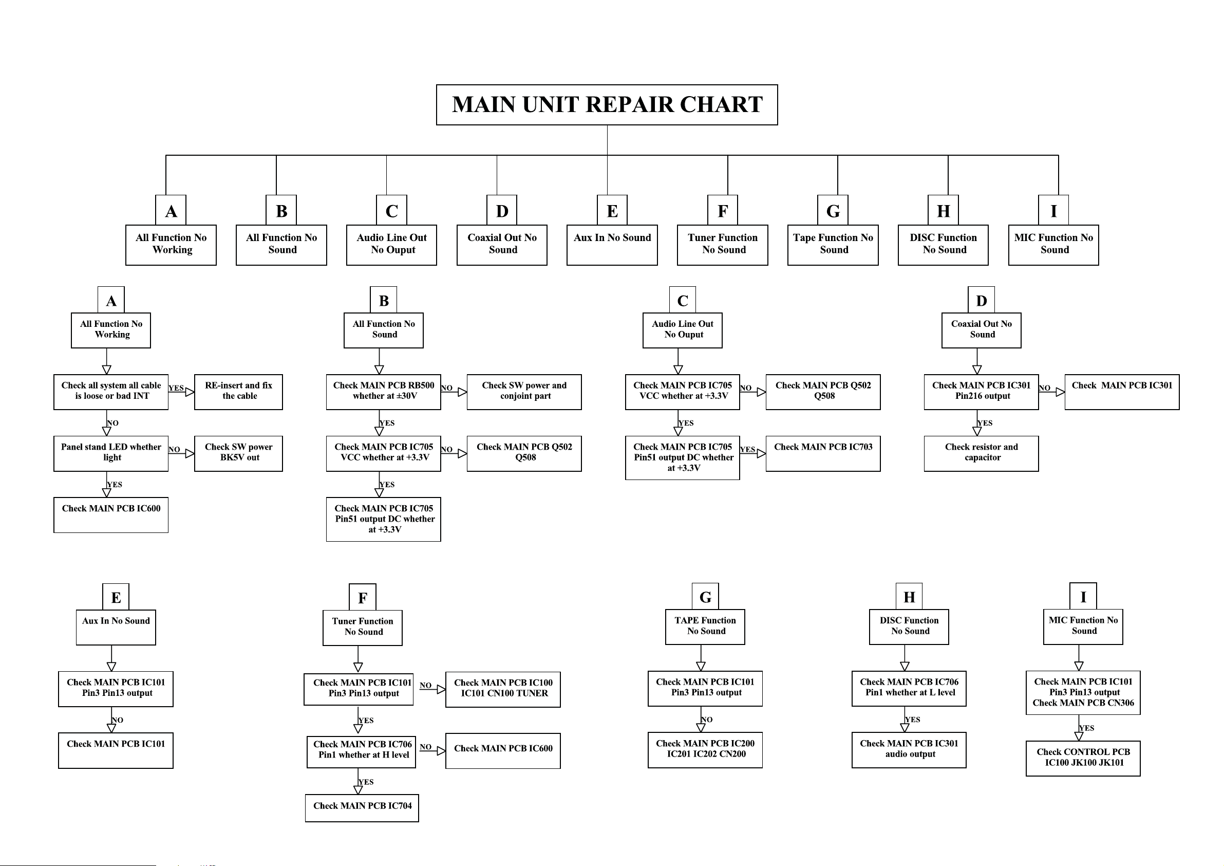
REPAIR INSTRUSTRATOR
2 - 22 - 2
 Loading...