

Philips FWC-870 Service Manual

Mini System
FW-C870/21/37 & FW -P880/37
Service
Service
Service
Service Manual
TABLE OF CONTENTS
Page
Location of pc boards & Version variations................1-2
Technical Specifications .............................................1-3
Measurement setup....................................................1-4
Service Aids, Safety Instruction, etc. ..........................1-5
Instruction for use : FW-C870/21 version excerpt.....2-1
Additional Features FW-P880/37 ... 2-13
Disassembly Instructions & Service positions ...........3-1
Service Test Programs ...............................................3-4
Set Block diagram .........................................................4
Set Wiring diagram ........................................................ 5
Front Board....................................................................6
Tuner Board: ECO5 Sys .......................................... 7B
ETF7 ND Tape Module ..................................................9
3CDC-LC Module ........................................................ 10
3CDC-LC-MB Module............................................... 10A
Power 5-VA Module (120/130W Version).................... 11
AF8 Board....................................................................12
DPL Board ...................................................................13
Set Mechanical Exploded view & parts list ................. 14
COMPACT
DIGITAL AUDIO
©
Copyright 2000 Philips Consumer Electronics B.V. Eindhoven, The Netherlands
All rights reserved. No part of this publication may be reproduced, stored in a retrieval system or
transmitted, in any form or by any means, electronic, mechanical, photocopying, or otherwise
without the prior permission of Philips.
Published by BB 0045 Service Audio Printed in The Netherlands Subject to modification
CLASS 1
LASER PRODUCT
GB
3139 785 22560
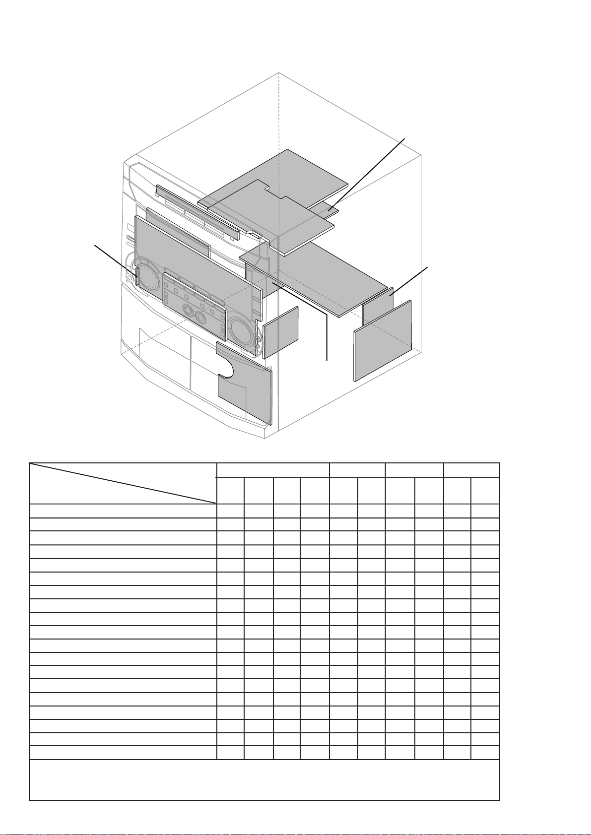
LOCATION OF PRINTED CIRCUIT BOARDS
CD KEY BOARD
1-2
AF8
TUNER
BOARD
BOARD
HEADPHONE
BOARD
DPL BOARD
FRONT
BOARD
CONTROL
CD
BOARD
POWER
SUPPLY
BOARD
BOARD
KARAOKE
BOARD
L/R AMP.
ETF7
BOARD
BOARD
VERSION VARIATIONS:
Type /Versions: FW-C870 FW-P880
Features &
/21 /37 /37
Board in used:
Aux/CDR In x x x
Line Out x x x
Surround Out x
Subwoofer Out x x x
Digital Out x x x
Matrix Surround
CD Text
Dolby B
RDS
News
Dolby Pro Logic (DPL) x
Incredible Surround
Karaoke Features x
Voltage Selector x
ECO Power Standby (Clock Display Off) x x x
Tuner board - ECO5 Sys x x x
Tuner board - Tuner 95
Center/Surround Channel x
C/S AMP.
BOARD
MAINS
BOARD
Note: 3CDC-LC-MB Module is mechanically the same as 3CDC-LC Module except the schematics, layouts & electrical
parts list related to the CDC Board.The CDC Board (recognized by 12NC :
3103 303 34522
printed on the Board)
is introduced as an alternative to supplement for the shortage of Servo IC TDA7073A.

SPECIFICATIONS
1-3
GENERAL:
Mains voltage : 110-127V/220-240V Switchable for /21/21M
120V for /37
220V for /33
220-230V for /22/34
230-240V for /30
Mains frequency : 50/60Hz
Power consumption : < 2W at ECO Power Standby
:< 20W at Standby
: 180W at Active
Clock accuracy : < 4 seconds per day
Dimension centre unit : 265 x 310 x 390mm
TUNER:
FM
Tuning range : 87.5-108MHz
65.81-74MHz for /34
1)
Grid : 50kHz (& 30kHz for /34)
100kHz for /37
IF frequency : 10.7MHz ± 25kHz
Aerial input : 75Ω coaxial
300Ω click fit for /37
Sensitivity at 26dB S/N : < 7µV
Selectivity at 600kHz bandwidth : > 25dB
Image rejection : > 25dB [> 75dB]
Distortion at RF=1mV, dev. 75kHz : < 3%
-3dB Limiting point : < 8µV
Crosstalk at RF=1mV, dev. 40kHz : > 18dB
MW
Tuning range : 531-1602kHz
530-1700kHz for /21/21M/37
Grid : 9kHz
10kHz for /21/21M/37
IF frequency : 450kHz ± 1kHz
Aerial input : Frame aerial
Sensitivity at 26dB S/N : < 4.0mV/M
Selectivity at 18kHz bandwidth : > 18dB
IF rejection : > 45dB
Image rejection : > 28dB
Distortion at RF=50mV, m=80% : < 5%
LW
Tuning range : 153-279kHz
Grid : 3kHz
IF frequency : 450kHz ± 1kHz
Aerial input : Frame aerial
Sensitivity at 26dB S/N : [< 7.0mV/M]
Selectivity at 18kHz bandwidth : [> 24dB]
IF rejection : [> 26dB]
Image rejection : [> 35dB]
Distortion at RF=50mV, m=80% : [< 5%]
AMPLIFIER:
Output power (6Ω, 1kHz, 10% THD)
L & R : 2 x 150W RMS /FW-C870/21
Output power (6Ω, 60Hz-12.5kHz, 10% THD)
L & R : 2 x 120W FTC /FW-C870/37
L & R : 2 x 115W FTC /FW-P880/37
Surround : 2 x 25W /FW-P880/37
Center : 40W /FW-P880/37
Frequency response within -3dB : 60Hz-16kHz
Digital Sound Control (DSC) :
Optimal, Classic, Techno, Jazz, Rock, Vocal
Virtual Environment Control (VEC) :
Hall, Disco, Concert, Club, Cinema, Arcade
WOOX : 1, 2, 3
Dolby Pro Logic (DPL) : Dolby Surround
Dolby Center Phantom
Dolby 3 Stereo
Normal Stereo
Input sensitivity
Aux in : 500mV ± 2dB, 1kHz
CDR in : 800mV ± 2dB, 1kHz
Microphone : 4mV ± 2dB
Output sensitivity
Line out (Left/Right) : 500mV ± 2dB at 22 kΩ
Subwoofer out (100Hz) : 1.3V ± 2dB at 22 kΩ
at maximum volume
Surround out (1kHz) : 500mV ± 2dB at 22 kΩ
Digital out : IEC 958, 44.1kHz
Headphone output at 32Ω : 18mW ± 1dB
CASSETTE RECORDER:
Number of track : 2 x 2 stereo
Tape speed : 4.76 cm/sec ± 2%
Wow and flutter : < 0.4% (DIN)
Fast-wind/Rewind time C60 : 130 sec
Bias system : 75kHz ± 10kHz
Rec/Pb frequency response within 8dB : 80Hz - 12.5kHz
Signal to noise ratio (unweighted): > 44dB
COMPACT DISC:
Measurement done at Set level at 6Ω speaker loads.
Frequency response : < ±3dB for 63Hz-14kHz
Signal to Noise ratio (Unweighted) : 60dBA
Signal to Noise ratio (A-weighted) : 67dBA
THD (30Hz-16kHz) : 1.5%
Channel difference (250Hz-10kHz) : < ±2dB
Channel separation (20Hz-20kHz) : 30dB
(1kHz) : 40dB
[....] Values indicated are for "Tuner 95 Board" only.
1)
Default setting is OFF, to switch on please refer page 3-4.
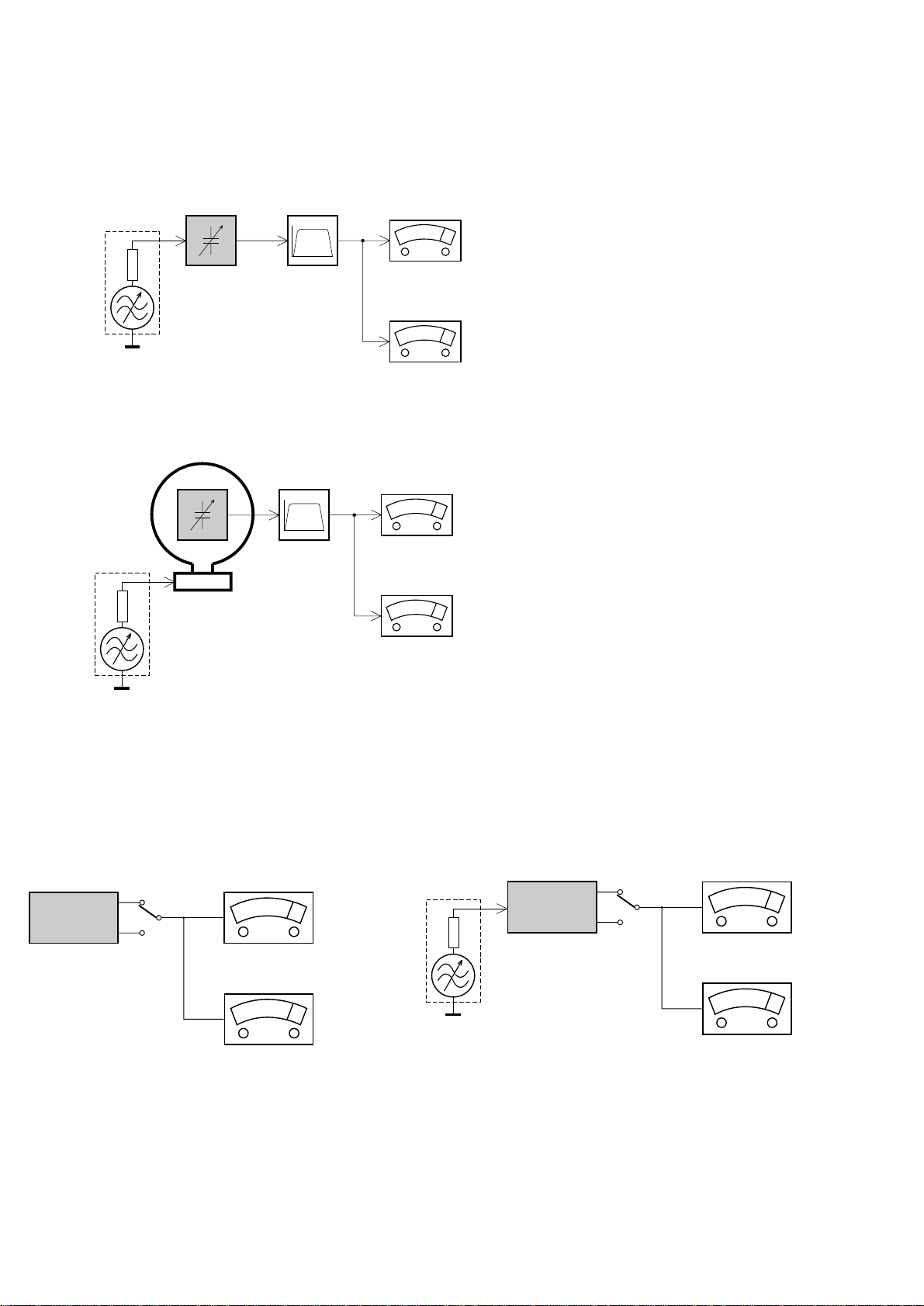
MEASUREMENT SETUP
Tuner FM
1-4
Bandpass
LF Voltmeter
e.g. PM2534
RF Generator
e.g. PM5326
DUT
250Hz-15kHz
e.g. 7122 707 48001
Ri=50Ω
S/N and distortion meter
e.g. Sound Technology ST1700B
Use a bandpass filter to eliminate hum (50Hz, 100Hz) and disturbance from the pilottone (19kHz, 38kHz).
Tuner AM (MW,LW)
RF Generator
e.g. PM5326
Ri=50Ω
DUT
Frame aerial
e.g. 7122 707 89001
Bandpass
250Hz-15kHz
e.g. 7122 707 48001
LF Voltmeter
e.g. PM2534
S/N and distortion meter
e.g. Sound Technology ST1700B
To avoid atmospheric interference all AM-measurements have to be carried out in a Faraday´s cage.
Use a bandpass filter (or at least a high pass filter with 250Hz) to eliminate hum (50Hz, 100Hz).
CD
Use Audio Signal Disc
(replaces test disc 3)
DUT
L
R
SBC429 4822 397 30184
S/N and distortion meter
e.g. Sound Technology ST1700B
LEVEL METER
e.g. Sennheiser UPM550
with FF-filter
Recorder
Use Universal Test Cassette CrO2 SBC419 4822 397 30069
or Universal Test Cassette Fe SBC420 4822 397 30071
LF Generator
e.g. PM5110
DUT
L
R
S/N and distortion meter
e.g. Sound Technology ST1700B
LEVEL METER
e.g. Sennheiser UPM550
with FF-filter
SERVICE AIDS
1-5
Service Tools:
Universal Torx driver holder .................................. 4822 395 91019
Torx bit T10 150mm ............................................. 4822 395 50456
Torx driver set T6 - T20......................................... 4822 395 50145
Torx driver T10 extended ...................................... 4822 395 50423
Cassette:
SBC419 Test cassette CrO2................................. 4822 397 30069
SBC420 Test cassette Fe ..................................... 4822 397 30071
MTT150 Dolby level 200nWb/M............................ 4822 397 30271
Compact Disc:
SBC426/426A Test disc 5 + 5A ............................ 4822 397 30096
SBC442 Audio Burn-in Test disc 1kHz ................. 4822 397 30155
SBC429 Audio Signals disc .................................. 4822 397 30184
Dolby Pro-logic Test Disc...................................... 4822 395 10216
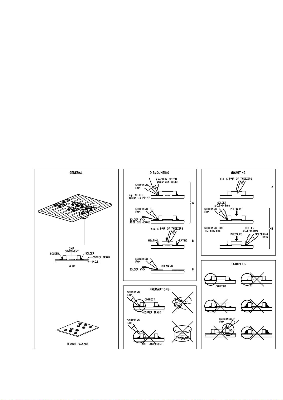
HANDLING CHIP COMPONENTS
ESD Equipment:
Anti-static table mat - large 1200x650x1.25mm ... 4822 466 10953
Anti-static table mat - small 600x650x1.25mm..... 4822 466 10958
Anti-static wristband .............................................. 4822 395 10223
Connector box (1MΩ) ............................................ 4822 320 11307
Extension cable
(to connect wristband to conn. box).................. 4822 320 11305
Connecting cable
(to connect table mat to conn. box) .................. 4822 320 11306
Earth cable (to connect product to mat or box) .... 4822 320 11308
Complete kit ESD3
(combining all above products)......................... 4822 320 10671
Wristband tester .................................................... 4822 344 13999
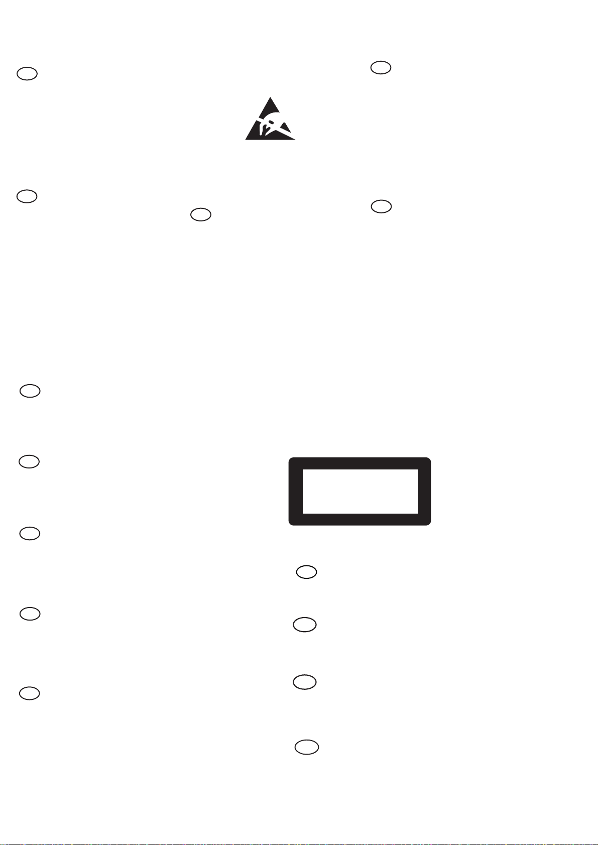
WARNING
GB
All ICs and many other semi-conductors are
susceptible to electrostatic discharges (ESD).
Careless handling during repair can reduce life
drastically.
When repairing, make sure that you are
connected with the same potential as the mass
of the set via a wrist wrap with resistance.
Keep components and tools also at this
potential.
F
ATTENTION
Tous les IC et beaucoup d’autres
semi-conducteurs sont sensibles aux
décharges statiques (ESD).
Leur longévité pourrait être considérablement
écourtée par le fait qu’aucune précaution n’est
prise à leur manipulation.
Lors de réparations, s’assurer de bien être relié
au même potentiel que la masse de l’appareil et
enfiler le bracelet serti d’une résistance de
sécurité.
Veiller à ce que les composants ainsi que les
outils que l’on utilise soient également à ce
potentiel.
1-6
ESD
D
WARNUNG
Alle ICs und viele andere Halbleiter sind
empfindlich gegenüber elektrostatischen
Entladungen (ESD).
Unsorgfältige Behandlung im Reparaturfall kan
die Lebensdauer drastisch reduzieren.
Veranlassen Sie, dass Sie im Reparaturfall über
ein Pulsarmband mit Widerstand verbunden
sind mit dem gleichen Potential wie die Masse
des Gerätes.
Bauteile und Hilfsmittel auch auf dieses gleiche
Potential halten.
WAARSCHUWING
NL
Alle IC’s en vele andere halfgeleiders zijn
gevoelig voor electrostatische ontladingen
(ESD).
Onzorgvuldig behandelen tijdens reparatie kan
de levensduur drastisch doen verminderen.
Zorg ervoor dat u tijdens reparatie via een
polsband met weerstand verbonden bent met
hetzelfde potentiaal als de massa van het
apparaat.
Houd componenten en hulpmiddelen ook op
ditzelfde potentiaal.
I
AVVERTIMENTO
Tutti IC e parecchi semi-conduttori sono
sensibili alle scariche statiche (ESD).
La loro longevità potrebbe essere fortemente
ridatta in caso di non osservazione della più
grande cauzione alla loro manipolazione.
Durante le riparazioni occorre quindi essere
collegato allo stesso potenziale che quello della
massa dell’apparecchio tramite un braccialetto
a resistenza.
Assicurarsi che i componenti e anche gli utensili
con quali si lavora siano anche a questo
potenziale.
GB
Safety regulations require that the set be restored to its original
condition and that parts which are identical with those specified,
be used.
NL
Veiligheidsbepalingen vereisen, dat het apparaat bij reparatie in
zijn oorspronkelijke toestand wordt teruggebracht en dat onderdelen,
identiek aan de gespecificeerde, worden toegepast.
F
Les normes de sécurité exigent que l’appareil soit remis à l’état
d’origine et que soient utiliséés les piéces de rechange identiques
à celles spécifiées.
D
Bei jeder Reparatur sind die geltenden Sicherheitsvorschriften zu
beachten. Der Original zustand des Geräts darf nicht verändert werden;
für Reparaturen sind Original-Ersatzteile zu verwenden.
“Pour votre sécurité, ces documents
doivent être utilisés par des spécialistes agréés, seuls habilités à réparer
votre appareil en panne”.
CLASS 1
LASER PRODUCT
GB
Warning !
Invisible laser radiation when open.
Avoid direct exposure to beam.
S
Varning !
Osynlig laserstrålning när apparaten är öppnad och spärren
är urkopplad. Betrakta ej strålen.
3122 110 03420
I
Le norme di sicurezza esigono che l’apparecchio venga rimesso
nelle condizioni originali e che siano utilizzati i pezzi di ricambio
identici a quelli specificati.
"After servicing and before returning set to customer perform a
leakage current measurement test from all exposed metal parts to
earth ground to assure no shock hazard exist. The leakage current
must not exceed 0.5mA."
Varoitus !
SF
Avatussa laitteessa ja suojalukituksen ohitettaessa olet alttiina
näkymättömälle laserisäteilylle. Älä katso säteeseen!
DK Advarse !
Usynlig laserstråling ved åbning når sikkerhedsafbrydere er
ude af funktion. Undgå udsaettelse for stråling.
2-1
3
DISC CHANG E
DISC 1 DISC 2 DISC 3
OPEN•CLOSE
STANDBY ON
DC
3
CHANGER
M NI HIFI SYSTEM
DUB
(HSD
RECORD
AUTO
REVERSE
DM
CLOCK/
TMER
PROG
ECO POWER
R SENSOR
V
O
L
U
M
E
B
A
S
S
T
R
E
B
L
E
TAPE
CD
TUNER
AUX
P
E
R
S
O
N
A
L
D
S
C
V
E
C
TAPE 1• 2
CD 1•2•3
BAND
CDR/DVD
STOP•CLEAR
SEARCH TUN NG PLAY PAUSE
PREV NEXTSDE
PRESET
▲
▲
1
2
3
4
5
6
7
8
9
§
0
!
@
#
$
%
^
&
*
¡™£
≤
∞
DEMO STOP
OPEN
OPEN
JOG CONTROL
wOOx
DYNAMC AMPL F CAT ON CONTROL
ON•OFF
LEVEL
MC LEVEL
(
)
BASS
TREBLE
™
6
English
Contents
General Information
Environmental Information ................................ 7
Acknowledgement ............................................... 7
Supplied Accessories ........................................... 7
Safety Information ................................................ 7
Preparations
Rear Connections ............................................ 8–9
Optional Connections ........................................ 9
Inserting batteries into the remote
control .................................................................... 9
Controls
Controls on the system and remote
control ........................................................... 10–11
Basic Functions
Demonstration mode ........................................ 12
Easy Set ................................................................. 12
Switching the system on ................................... 13
Switching the system to Standby mode ........ 13
Switching the system to Eco Power
Standby mode ..................................................... 13
Power Saving Automatic Standby .................... 13
Dim mode ............................................................ 13
Volume Control .................................................. 14
Interactive Sound Control ........................ 14–15
CD Operation
Discs for Playback .............................................. 16
Loading Discs ...................................................... 16
Disc Playback ....................................................... 17
Programming the disc tracks .................... 17–18
Repeat ................................................................... 18
Shuffle .................................................................... 18
Radio Reception
Storing Preset Radio Stations ................... 19–20
Tuning to Preset Radio Stations ...................... 20
Changing Tuning Grid ........................................ 20
Karaoke
Microphone mixing ............................................ 20
Ta pe Operation/Recording
Ta pe Playback ............................................... 21–22
General Information on Recording ................ 22
Preparation for Recording ............................... 22
One Touch Recording/Recording the
mixed sound ........................................................ 22
CD Synchro Recording .............................. 22–23
Dubbing Tapes ..................................................... 23
Digital Recording via Digital Out .................... 23
External Sources
Listening to External Sources .......................... 23
Clock/Timer
View Clock .......................................................... 24
Clock Setting ....................................................... 24
Timer Setting ................................................ 24–25
Sleep Timer Setting ............................................ 25
Specifications
........................................... 26
Maintenance
.............................................. 27
Tr oubleshooting
............................. 27
–
28
2-2
7
English
General Information
IMPORTANT!
PLEASE NOTE THAT THE VOLTAGE
SELECTOR LOCATED AT THE REAR OF
THIS SYSTEM IS PRESET AT 220V FROM
THE FACTORY. FOR COUNTRIES THAT
OPERATE AT 110V-127V, PLEASE ADJUST
TO 110V-127V BEFORE YOU SWITCH ON
THE SYSTEM.
Environmental Information
All unnecessary packaging has been omitted. We
have tried to make the packaging easy to
separate into three materials: cardboard (box),
polystyrene foam (buffer) and polyethylene (bags,
protective foam sheet).
Your system consists of materials which can be
recycled and reused if disassembled by a
specialised company. Please observe the local
regulations regarding the disposal of packaging
materials, exhausted batteries and old
equipment.
Acknowledgement
Energy Star
As an ENERGY STARRPartner; Philips has
determined that this product
meets the ENERGY STAR
R
guidelines for energy
efficiency.
Supplied accessories
– Remote control
– Batteries (two AA size) for remote control
– AM loop antenna
– FM wire antenna
–AC power cord
Safety Information
● Before operating the system, check that the
operating voltage indicated on the typeplate (or
the voltage indication beside the voltage
selector) of your system is identical with the
voltage of your local power supply. If not, please
consult your dealer.
● Place the system on a flat, hard and stable
surface.
● Place the system in a location with adequate
ventilation to prevent internal heat build-up in
your system. Allow at least 10 cm (4 inches)
clearance from the rear and the top of the unit
and 5 cm (2 inches) from each side.
● Do not expose the system, batteries or discs to
excessive moisture, rain, sand or heat sources
caused by heating equipment or direct sunlight.
● If the system is brought directly from a cold to a
warm location, or is placed in a very damp room,
moisture may condense on the lens of the disc
unit inside the system. Should this occur, the CD
player would not operate normally. Leave the
power on for about one hour with no disc in the
system until normal playback is possible.
● The mechanical par ts of the set contain self-
lubricating bearings and must not be oiled or
lubricated.
● When the system is switched to Standby
mode, it is still consuming some power.
To disconnect the system from the
power supply completely, remove the AC
power plug from the wall socket.
8
English
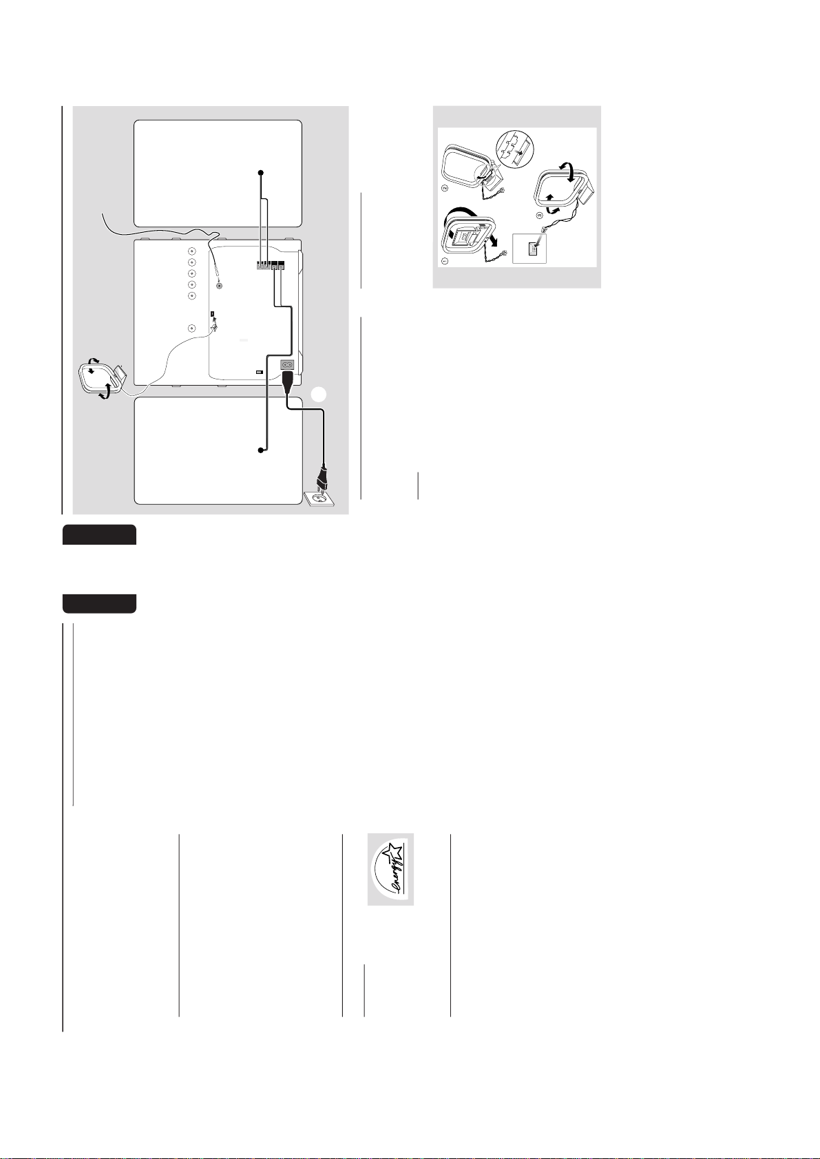
Preparations
Rear Connections
The type plate is located at the rear of the
system.APowe r
Before connecting the AC power cord to the
wall outlet, ensure that the following are done;
– If your system is equipped with a Voltage
Selector, set the VOLTAGE SELECTOR to the
local power line voltage.
– All other connections have been made.
WARNING
–For opt mal performance, use only the
original power cable.
–Never make or change any connections
with the power switched on.
To avoid overheating of the system, a safety
c rcuit has been built in. Therefore, your
system may sw tch to Standby mode
automatically under extreme conditions. If
this happens, let the system cool down
before reusing t (not available for all versions).
B
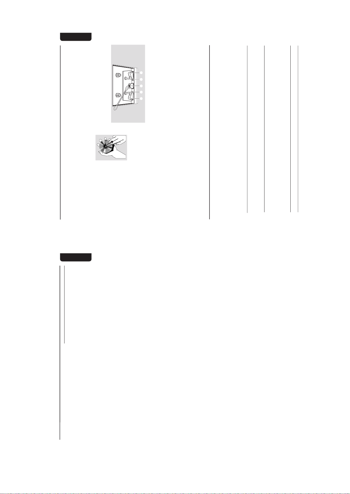
Antennas Connection
Connect the supplied AM loop antenna and FM
antenna to the respective terminals. Adjust the
position of the antenna for optimal reception.
AM Antenna
AM ANTENNA
Fix the claw
to the slot
● Position the antenna as far as possible from a TV,
VCR or other radiation source.
AM ANTENNA
AUXCDR N
SUB-
WOOFER
OUT
DG TAL
OUT
LNE OUT
LRLR
AC
MANS
FRONT
speaker
(right)
L
+
–
R
–
+
A
speaker
(left)
AM loop
antenna
FM wire antenna
AC power cord
B
C
FMANTENNA 75Ω
VOLTAGE
SELECTOR
0V
27V
220V
240V
2-3
9
English
Preparations
FM Antenna
● For better FM stereo reception, connect an
outdoor FM antenna to the FM ANTENNA
terminal.
C
Speakers Connection
Front Speakers
Connect the speaker wires to the SPEAKERS
(FRONT) terminals, right speaker to "R" and left
speaker to "L", colored (marked) wire to "+"
and black (unmarked) wire to "-".
1
● Clip the stripped portion of the speaker wire as
shown.
Notes:
–For optimal sound performance, use the
supplied speakers.
– Do not connect more than one speaker to any
one pair of
+
/
-
speaker terminals.
– Do not connect speakers with an impedance
lower than the speakers supplied. Please refer to
the SPECIFICATIONS section of this manual.
Optional Connections
The optional equipment and connecting cords
are not supplied. Refer to the operating
instructions of the connected equipment for
details.
Line Out Connection
Connect this output to any analogue audio
equipment for playback or recording (CD
recorder, tape recorder or amplifier for example).
Use a cinch cable to connect the LINE OUT
terminals to the analogue audio in terminals of
the equipment.
Connecting other equipment to your
system
Connect the audio left and right OUT terminals
of a TV, VCR, Laser Disc player, DVD player or
CD Recorder to the AUX/CDR IN terminals.
Notes:
– Do not connect equipment to both the LINE
OUT and AUX/CDR IN terminals at the same time.
Otherwise, noise will be generated and malfunction
might occur.
– If you are connecting equipment with a mono
output (a single audio out terminal), connect it to
the AUX/CDR IN left terminal. Alternatively, you
can use a “single to double” cinch cable (still be
mono sound).
Subwoofer Out Connection
Connect the subwoofer to the SUBWOOFER
OUT terminal. The subwoofer reproduces just
the low bass sound effect (explosions or the
rumble of spaceships, for example).
Digital Out Connection
Connect this digital output when recording on
any audio equipment with digital input (CD
Recorder, Digital Audio Tape [DAT] deck, Digital
to Analogue Converter and Digital Signal
Processor, for example). Use a cinch cable to
connect the DIGITAL OUT terminal to the
digital input terminal of the equipment.
Inserting batteries into the
Remote Control
Insert two batteries
(Type R06 or AA) into
the remote control with
the correct polarity as
indicated by the + and
- symbols inside the
battery compar tment.
CAUTION
– Remove batteries if they are exhausted
or not to be used for a long t me.
– Do not use old and new or different
types of batteries in combination.
– Batteries contain chemical substances , so
they should be disposed off properly.
10
English
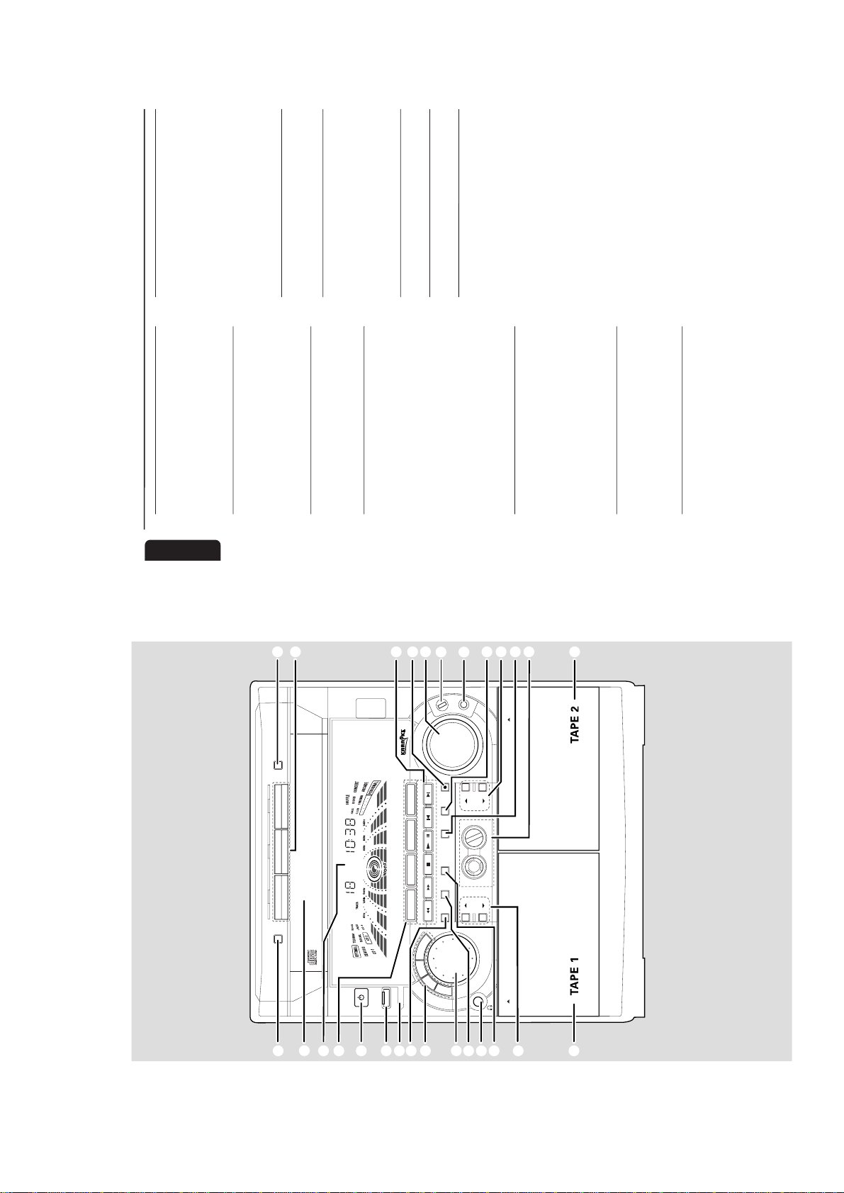
Controls
(main system’s illustration on page 3)
Controls on the system and
remote control
1
STANDBY ON
y
y
– to switch the system on or to Standby mode.
– to start EASY SET operation.
2
ECO POWER
– to activate or deactivate Eco Power Standby
mode.
3
iR SENSOR
– infrared sensor for remote control.
4
PROG (PROGRAM)
for CD .................to programme disc tracks.
for TUNER ........ to programme preset radio
stations.
for CLOCK ....... (on the system only) to select 12-
or 24-hour clock mode.
5
INTERACTIVE SOUND CONTROLS
– to select the desired sound feature : PERSONAL,
DSC, VEC or BASS/TREBLE.
6
JOG CONTROL
– to select the desired sound effect for the
respective sound feature selected.
PERSONAL ..... PERSONAL 1-6, six personal
preferred Spectrum Analyser
settings.
DSC ..................OPTIMAL, CLASSIC, TECHNO,
VOC AL, ROCK or JAZZ.
VEC .................. HALL, CLUB, DISCO, CINEMA,
CONCERT or ARCADE.
7
CLOCK/TIMER
– to view the clock, set the clock or set the timer.
8
n
– to connect headphones.
9
DIM
– to select brightness of the display screen :
DIM 1, DIM 2, DIM 3 or DIM OFF.0SOURCE – to select the following:
CD / (CD 1•2•3)
– to select disc tray 1, 2 or 3.
TUNER / (BAND)
– to select waveband : FM or MW.
TAPE / (TAPE 1• 2)
– to select tape deck 1 or 2.
AUX / (CDR/DVD)
– to select a connected external source :
CDR/DVD or AUX (auxiliar y) mode.
!
DISPLAY SCREEN
– to view the current status of the system.
@
DISC TRAY
#
DISC CHANGE
– to change disc(s).
$
OPEN•CLOSE
– to open or close the disc tray.
%
DISC 1 / DISC 2 / DISC 3 (CD DIRECT)
– to select a disc tray for playback.
^
Mode Selection
SEARCH• TUNING àá
for CD .................to search backward/forward.
for TUNER ......... to tune to a lower or higher radio
frequency.
for TAPE.............. to rewind or fast forward.
for CLOCK ....... (on the system only) to set the
hour.
STOP•CLEAR Ç (DEMO STOP)
for CD .................to stop playback or to clear a
programme.
for TUNER ........ to stop programming.
for TAPE.............. to stop playback or recording.
for DEMO .........(on the system only) to activate/
deactivate the demonstration.
PLAY PAUSE ÉÅ
for CD .................to start or interrupt playback.
for TAPE .............. to start playback.
í PREV / SIDE / NEXT ë
(PRESET 4 3 )
for CD .................to skip to the beginning of the
current, previous, or next track.
for TUNER ........ to select a preset radio station.
for TAPE.............. to select tape side (back or
front) in tape deck 2 only.
for CLOCK ....... (on the system only) to set the
minute.
&
RECORD
– to start recording on tape deck 2.
*
VOLUME
– to increase or decrease the volume.
(
MIC LEVEL
– to adjust the mixing level for karaoke or
microphone recording.
)
MIC JACK
– to connect microphone jack.
¡
DUB (HSD) (HIGH SPEED DUBBING)
– to dub a tape in normal or fast speed.
™
BASS/TREBLE CONTROL – to adjust the
BASS/TREBLE level :
BASS # $ (BASS +/-)
– to increase or decrease the low tone level.
TREBLE # $ (TREBLE +/-)
– to increase or decrease the high tone level.

2-4
11
English
Controls
0
•
*
^
4
9
ª
º
≤
™
5
⁄
¤
^
^
*
£
‹
›
1
3
DSC
BASS
ÅÉ
1
3
2
4
6
5
7
9
8
VOLUME
á
à
2
ë
í
Ç
0
2
AUX/CDR
MUTE
CD 123
TUNER
TAPE 1/2
AUTO REV.CLOCK
SHUFFLE
PERSONAL
BASS/TREBLE
DIM PROGRAM
REPEAT
TREBLE
+
-
CD
DIRECT
VEC
TMER ON/OFF SLEEP
WOOX
WOOX LEVEL
+
-
≥
%
£
AUTO REVERSE
– to select the desired playback modes in tape
deck 2 only.
≤
wOOx ON•OFF
– to select enhanced or normal wOOx sound
effect.
wOOx LEVEL
– to select desired wOOx level : WOOX 1,
WOOX 2 or WOOX 3.
∞
TAPE DECK 2
§
TAPE DECK 1
≥
MUTE
– to inter rupt or resume sound reproduction.
•
CLOCK
– to view the clock display.
ª
TIMER ON/OFF
– to activate or deactivate the timer function.
º
SLEEP
– to activate , deactivate or set the sleep timer
function.⁄SHUFFLE
– to playback all available discs and their tracks/
programme in random order.
¤
REPEAT
– to playback track(s)/disc(s)/programme
repeatedly.‹DIGITS 0 – 9
(numbers consisting of more than two figures must
be keyed in within 2 seconds.)
for CD .................to key in a CD track for playback
or programming.
for TUNER ........ to key in a preset radio station.
›
B
– to switch the system to Standby mode or Eco
Power Standby mode.
Notes for remote control:
– Fir st, select the source you wish to
control by pressing one of the source select
keys on the remote control (CD 123 or
TUNER for example).
– Then select the desired function (
É
,
í
,
ë
for example).
12
English
Basic Functions
IMPORTANT!
Before you operate the system, complete
the preparation procedures.
Demonstration mode
The system has a demonstration mode that
shows the various features offered by the system.
To activate the demonstration
● In Standby mode, press and hold DEMO
STOPÇon the system until "DEMO ON" is
displayed.
➜ The demonstration will begin.
To deactivate the demonstration
● Press and hold DEMO STOP Çon the system
until "DEMO OFF" is displayed.
➜ The system will switch to Standby mode.
Notes:
– Even if you remove the AC power cord and
reconnect it to the wall socket, the demonstration
will remain off until you activate it again.
– When the power is turned on, the disc tray may
open and close to initialize the system.
Easy Set
EASY SET allows you to store all available radio
stations automatically.
● In Standby or Demonstration mode, press and
hold STANDBY ON until "EASY SET" is
displayed.
➜ The system will search for all radio stations
on the FM band, then the MW band.
➜ All available radio stations with sufficient signal
strength will be stored automatically.
➜ The system will stop searching when all the
available radio stations are stored or when the
memory for 40 preset radio stations is used.
➜ The last preset radio station will play when
EASY SET is completed.
Note:
– When EASY SET is used, all previously stored
radio stations will be replaced.
M N H F SYSTEM
DUB
(HSD)
RECORD
DM
CLOCK/
TMER
PROG
V
O
L
U
M
E
STOP•CLEAR
SEARCH•TUNNG PLAY PAUSE
PREV NEXTS DE
PRESET
▲
▲
1
3
DSC
BASS
ÅÉ
1
3
2
4
6
5
7
9
8
VOLUME
á
à
2
ë
í
Ç
0
2
AUX/CDR
MUTE
CD 123
UNER TAPE 1/2
AUTO REVC OCK
SHUFFLE
PERSONAL
BASSTREBL
DM PROGRAM
REPEAT
TREBLE
+
-
CD
DRECT
VEC
TMER ON/OFFS EEP
WOOX
WOOX LEVEL
+
-
+
-
DSC
BASS
TREBLE
B
A
S
S
/
T
R
E
B
L
E
P
E
R
S
O
N
A
L
D
S
C
V
E
C
TAPE 1•2
CD 1•2•3
BAND
CDR/DVD
TAPE
CD
TUNER
AUX
R SENSOR
AUTO
REVERSE
ECO POWER
DEMO STOP
JOG CONTROL
STANDBY-ON
wOOx
DYNAMC AMPL F CAT ON CONTROL
ON•OFF
LEVEL
MC LEVEL
2-5
13
English
Switching the system on
In Standby mode
● Press STANDBY ON or CD/TUNER/
TAPE/AUX on the system.
➜ The system will switch to the last selected
source or the selected source.
● Press any one of the DISC DIRECT PLAY
buttons or OPEN•CLOSE.
➜ The system will switch to CD mode.
In Eco Power Standby mode
● Press CD 123, TUNER, TAPE 1/2 or AUX/
CDR on the remote control.
➜ The system will switch to the selected source.
Switching the system to Standby
mode
In Demonstration mode
● Press and hold DEMO STOP Ç on the
system.
In Eco Power Standby mode
● Press ECO POWER.
In any other source mode
● Press STANDBY ON (or B on the remote
control).
➜ The clock will appear on the display when the
system is in Standby mode.
Switching the system to Eco
Power Standby mode
● Press ECO POWER (or press and hold B on
the remote control).
➜ "LOW POWER STANDBY ON" will be
displayed, then the display screen will go blank.
➜ The low power ECO POWER LED will be
lighted.
Note:
– If you have not deactivated the demonstration, it
will resume five seconds after the system switches
to Eco Power Standby or Standby mode.
Power Saving Automatic Standby
As a power-saving feature, the system will
automatically switch to Standby mode if you do
not press any buttons within 30 minutes after a
disc or tape has stopped playing.
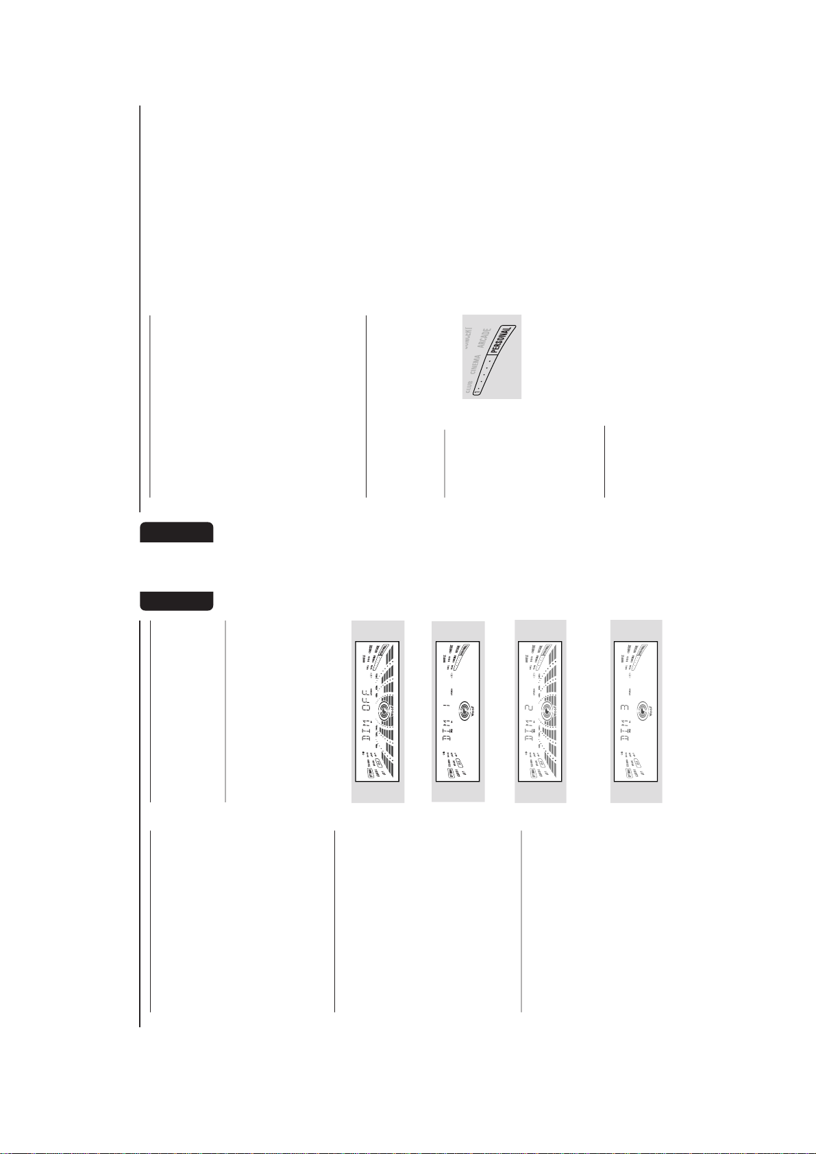
Dim mode
You can select the desired brightness for the
display.
● Press DIM repeatedly to select DIM 1, DIM 2,
DIM 3 or DIM OFF.
➜
DIM
appears on the display, except for DIM
OFF mode.
DIM OFF - normal brightness with
Spectrum Analyser On
DIM 1 - normal brightness w th Spectrum
Analyser Off
DIM 2 - half brightness with Spectrum
Analyser On
DIM 3 - half brightness with Spectrum
Analyser Off and all LEDs on the system
will be switched off.
Basic Functions
14
English
Volume Control
Adjust VOLUME to increase (turn knob
clockwise or press VOLUME +) or decrease
(turn knob anti-clockwise or press VOLUME -)
the sound level.
To listen through the headphones
● Connect the headphones plug to the n socket
at the front of the system.
➜ The speakers will be muted.
To switch off the volume temporarily
● Press MUTE on the remote control.
➜ Playback will continue without sound and
"MUTE" will be displayed.
● To restore the volume, press MUTE again or
increase the VOLUME level.
Interactive Sound Control
For optimal sound listen ng, select only one
of the following interactive sound controls
at a t me : PERSONAL, DSC, VEC or BASS/
TREBLE.
Personal Sound
1
Press PERSONAL.2Adjust the JOG
CONTROL (or press
PERSONAL on the
remote control
repeatedly) to select the desired Personal setting.
➜ The selected Personal setting number will
appear on the display.
➜ If no name has been stored previously,
“PERSONAL X" will be displayed. "X" is the
setting number.
Personal Setting
You can use the JOG CONTROL to adjust the
Per sonal setting to your desired level. Up to 6
Per sonal settings can be stored.
1
Press and hold PERSONAL on the system
until "SELECT PRESET NUMBER" is displayed.2Adjust the JOG CONTROL to select the
desired Personal setting number and press á
on the system to confirm the selection.
➜ "ADAPT LOW FREQ LEVEL" will be
displayed.
3
Adjust the JOG CONTROL to select the
desired Spectrum Analyser band level for low
frequency.
➜ The level will increase or decrease
between+3 and -3.
4
Press á to confirm the selection.
➜ "ADAPT MID FREQ LEVEL" will be
displayed, followed by "ADAPT HIGH FREQ
LEVEL".
● Repeat steps 3–4 to select the desired middle
and high frequency Spectrum Analyser band
levels.5You can edit the name for the personal setting.
➜ The first character of the setting name will be
flashing.
6
Adjust the JOG CONTROL to select the
desired letter, number or symbol.
➜ "A to Z", "0 to 9" or "*, -, +, \, /, _".7Press á to confirm the selection.
➜ The next character for editing will be flashing.
● Repeat steps 6–7 to store up to 10 characters.
8
To store the setting, press PERSONAL on the
system again.
To change any previous setting before
storing
● Press à on the system to retrace the steps in
reverse order and make the changes accordingly.
To exit without storing the setting
● Press Çon the system.
Notes:
– During personal setting, if no button is pressed
within 90 seconds, the system will exit the Personal
setting mode automatically.
– The wOOx level cannot be stored as par t of the
Personal setting.
– When making a Personal setting, it is not
possible to adjust the Bass/Treble level, "USE
JOG" will be displayed.
Basic Functions
2-6
15
English
Digital Sound Control (DSC)
The DSC feature enables you to adjust the
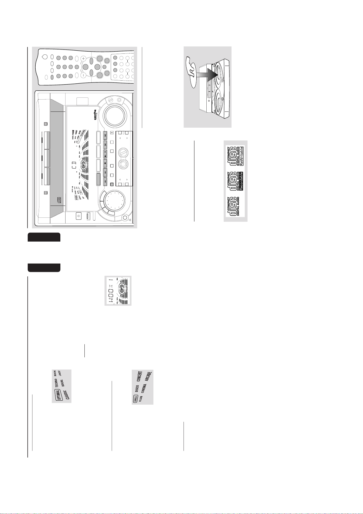
system to suit your type of music.1Press DSC.2Adjust the JOG
CONTROL (or press
DSC on the remote control
repeatedly) to select the desired Digital Sound
Control effect : OPTIMAL, CLASSIC, TECHNO,
VOC AL, ROCK or JAZZ.
➜ The selected DSC will be encircled.
Note:
–For a neutral sound effect, select CLASSIC.
Virtual Environment Control (VEC)
The VEC feature enables you to adjust the
system to select a type of environment.
1
Press VEC.2Adjust the JOG
CONTROL (or press
VEC on the remote
control repeatedly) to
select the desired Vir tual Environment Control
effect : HALL, CLUB, DISCO, CINEMA,
CONCERT or ARCADE.
➜ The selected VEC will be encircled.
BASS/TREBLE
The BASS/TREBLE feature enables you to define
the sound-processor settings for Bass and Treble.
1
Press BASS/TREBLE.
➜ The BASS and TREBLE LEDs will be lighted.
➜ "ADAPT BASS AND TREBLE LEVELS"
will be displayed.2Use the BASS/TREBLE controls to select the
desired BASS or TREBLE levels respectively.
➜ The BASS/TREBLE level will increase or
decrease between level +3 and -3.
● Press BASS # or $ (or BASS +/- on the
remote control) repeatedly to select the low
tone level.
➜ "BASS -X" or "BASS +X" will be displayed.
● Press TREBLE # or $ (or TREBLE +/- on
the remote control) repeatedly to select the high
tone level.
➜ "TREBLE -X" or "TREBLE +X" will be
displayed.
Basic Functions
Note:
–"
X
" denotes the sound level.
Automatic DSC-wOOx / VEC-wOOx
selection
The best wOOx setting is generated
automatically for each DSC or VEC selection.
You can manually select the wOOx setting that
best suits your listening environment.
wOOx
There are three wOOx settings to enhance the
bass response.
1
Press wOOx ON•OFF (or
wOOx on the remote
control) to switch ON
(enhanced) or OFF (normal)
the wOOx sound effect.
● When wOOx is switched on;
➜ The
WOOX
will appear on the display.
● When wOOx is switched off;
➜ The display will show "WOOX NORM" and
WOOX
will disappear from the display.
2
When wOOx is switched on, adjust wOOx
LEVEL to select the desired wOOx settings:
WOOX 1, WOOX 2 or WOOX 3.
Notes:
– When Personal or Bass/Treble sound control is
selected, wOOx will be switched off automatically.
– Some discs or tapes might be recorded in high
modulation, which causes a distortion at high
volume. If this occurs, deactivate wOOx or reduce
the volume.
16
English
CD Operation
DISC CHANGE
DISC 1 DISC 2 DISC 3
OPEN•CLOSE
DC
3
CHANGER
M N H F SYSTEM
DUB
(HSD)
RECORD
DM
CLOCK/
TMER
PROG
V
O
L
U
M
E
STOP CLEAR
SEARCH•TUNNG PLAY PAUSE
PREV NEXTS DE
PRESET
▲
▲
R SENSOR
AUTO
REVERSE
ECO POWER
DEMO STOP
JOG CONTROL
STANDBY-ON
1
3
BASS
1
3
2
4
6
5
7
9
8
VOLUME
á
à
2
ë
í
Ç
0
2
AUX CDR
MUTE
CD 123
TUNER TAPE 1 2
AUTO REVCLOCK
SHUFFLE
PERSONAL
BASS/TREBLE
DM PROGRAM
REPEAT
TREBLE
CD
DRECT
VEC
TMER ON/OFF SLEEP
WOOX
WOOX LEVEL
+
-
+
-
ÅÉ
DSC
BASS
TREBLE
B
A
S
S
T
R
E
B
L
E
P
E
R
S
O
N
A
L
D
S
C
V
E
C
TAPE 1•2
CD 1•2•3
BAND
CDR/DVD
TAPE
CD
TUNER
AUX
wOOx
DYNAMC AMPL F CAT ON CONTROL
ON OFF
LEVEL
MC LEVEL
IMPORTANT!
– This system is designed for regular discs .
Therefore, do not use any accessories such
as disc stabiliser r ngs or disc treatment
sheets, etc., as offered on the market,
because they may jam the changer
mechanism.
– Do not load more than one disc into
each tray.
Discs for Playback
This system can playback all digital audio CD,
finalised digital audio CD-Recordable (CDR)
discs and finalised digital audio CD-Rewritable
(CDRW)discs.
Loading Discs
1
Press CD to select CD mode.2Press OPEN•CLOSE to open the disc tray.3Load up to two discs on the individual disc trays.
To load the third disc, press DISC CHANGE.
➜ The disc tray will rotate until the empty tray
is ready for loading.
2
2
1
D C CHAN E
1
4
Press OPEN•CLOSE to close the disc tray.
➜ "READING" will be displayed. The selected
disc, total number of tracks and the playing time
will appear on the display.
➜ A lighted button indicates that a disc is loaded
on the disc tray.
Notes:
– Load the discs with the label side facing up.
–To ensure good system performance, wait until
the disc tray completely reads the disc(s) before
proceeding.

2-7
17
English
CD Operation
Disc Playback
To playback all discs on the disc tray
● Press PLAYÉÅ.
➜ All the available discs will playback once, then
stop.
➜ During playback, the selected disc tray, track
number and elapsed playing time of the current
track will appear on the display.
To playback one disc only
● Press the DISC DIRECT PLAY button : DISC 1,
DISC 2 or DISC 3.
➜ The selected disc will playback once, then
stop.
To interrupt playback
● Press PA USEÉÅ.
● To resume playback, press PLAYÉÅ again.
To stop playback
● Press Ç.
To search for a particular passage during
playback
● Press and hold à or á and release it when
the desired passage is located.
➜ During searching, the volume will be reduced.
To select a desired track
● Press í or ë repeatedly (or Digits 0–9 on
the remote control) until the desired track
appears on the display.
● If playback is stopped, press PLAYÉÅ to start
playback.
Note:
– In Shuffle mode , pressing
í
will cause the
player to skip only to the beginning of the current
track.
To skip to the beginning of the current
track during playback
● Press í once.
Replace discs during playback
1
Press DISC CHANGE.2To change the inner disc, press DISC
CHANGE again.
➜ "DISC CHANGE" will be displayed and the
disc will stop playing.
➜ The disc tray will close to retrieve the inner
disc, then reopen with the inner disc accessible.
Programming the disc tracks
Programming tracks is possible when playback is
stopped. Up to 40 tracks can be stored in the
memory in any order.
1
Load the desired discs on the disc tray (refer to
“Loading Discs”).
2
Press PROG to start programming.
➜
PROGRAM
will start flashing.
3
Press CD (CD 1•2•3) or DISC 1/2/3 button
to select a disc.4Press í or ë (or Digits 0–9 on the remote
control) to select the desired track.
5
Press PROG to store the track.
● Repeat steps 3–5 to store other discs and
tracks.6Press PLAYÉÅ to star t programme playback.
➜ "PLAY PROGRAM" will be displayed.
● To end programming without star ting playback,
pressÇ once .
➜ The total number of tracks programmed and
the total playing time will appear on the display.
Notes:
– If the total playing time is more than "99:59"
or if one of the programmed tracks has a number
greater than 30, then "--:--" will appear on the
display instead of the total playing time.
– If you attempt to programme more than 40
tracks, "
PROGRAM FULL
" will be displayed.
– If you press any of the DISC DIRECT PLAY
buttons, the system will playback the selected disc
or track, and the stored programme will be ignored
temporarily. The
PROGRAM
symbol also will
disappear temporarily from the display. It will
reappear when playback of the selected disc ends.
– During programming, if no button is pressed
within 20 seconds, the system will exit the
Programme mode automatically.
18
English
To review the programme
● Stop playback and press í or ë repeatedly.
● To exit review mode, press Ç.
To erase the entire programme
● Press Ç once when playback is stopped or
twice during playback.
➜ "PROGRAM CLEARED" will be displayed.
➜
PROGRAM
will disappear from the display.
Note:
– The programme will be erased when the system
is disconnected from the power supply or when the
disc tray is opened.
Repeat
The current track, a disc, all available discs or all
programmed tracks can be played repeatedly.
1
Press REPEAT on the remote control
repeatedly to select various repeat modes.
● In normal playback
➜ "TRACK" – to repeat the current track.
"DISC" – to repeat the entire disc.
"ALL DISC" – to repeat all available discs.
➜
REPEAT
appears on the display.
● In programme playback
➜ "TRACK" – to repeat the current
programmed track.
"PROGRAM" – to repeat all programmed
tracks.
➜
REPEAT
and
PROGRAM
will appear on the
display.
● The selected track/disc(s)/progr amme will now
be played repeatedly until you press Ç.
2
To resume normal playback, press REPEAT
until the "OFF" mode is displayed.
➜
REPEAT
will disappear from the display.
Note:
– Selecting SHUFFLE during repeat playback will
cancel all repeat modes.
CD Operation
Shuffle
All the available discs and their tracks or all the
programmed tracks can be played in random
order.
1
Press SHUFFLE on the remote control.
➜ "SHUFFLE" and
SHUFFLE
will appear on the
display.
● The discs and the tr acks will be played in
random order until you press Ç.
2
To resume normal playback, press SHUFFLE
again.
➜
SHUFFLE
will disappear from the display.
When REPEAT is selected during
shuffling
● In normal shuffled playback
➜ "TRACK" and "ALL DISC" repeat modes are
available for selection.
➜
REPEAT
and
SHUFFLE
will appear on the
display.
● In programme shuffled playback
➜ "TRACK" or "PROGRAM" repeat modes are
available for selection.
➜
REPEAT
,
PROGRAM
and
SHUFFLE
will appear on
the display.
For Recording, please refer to “Tape
Operation/Recording”.
2-8
19
English
Radio Reception
M N H F SYSTEM
DUB
(HSD
RECORD
DM
CLOCK/
TMER
PROG
V
O
L
U
M
E
STOP•CLEAR
SEARCH•TUNNG PLAY PAUSE
PREV NEXTS DE
PRESET
▲
▲
1
3
ÅÉ
1
3
2
4
6
5
7
9
8
OLUME
á
à
2
ë
í
Ç
0
2
AUXCDR
MUTE
CD 123
TUNER
TAPE 1/2
AUTO REVCLOCK
SHUFFE
P RSONAL
BASS/TREBLE
DM PROGRAM
REPEAT
CD
DRECT
B
A
S
S
/
T
R
B
L
E
P
E
R
S
O
N
A
L
D
S
C
V
E
C
TAPE 1•2
CD 1•2•3
BAND
CDR/DVD
TAPE
CD
TUNER
AUX
R SENSOR
AUTO
REVERSE
ECO POWER
DEMO STOP
JOG CONTROL
STANDBY-ON
wOOx
DYNAMC AMPL F CAT ON CONTROL
ON•OFF
LEVEL
MC LEVEL
BASS
TREBLE
Storing Preset Radio Stations
You can store up to 40 preset radio stations in
the memory.
Automatic Preset Programming
● EASY SET setting (refer to “Basic Functions -
EAST SET”).
OR
1
Press TUNER (BAND) to select TUNER mode .
➜ "TUNER" will be displayed. A few seconds
later, the current radio frequency will be
displayed.
To begin automatic preset from a desired
preset number
● Press í or ë (or Digits 0–9 on the remote
control) to select the desired preset number.
➜ For those radio stations that had been stored
in one of the preset will not be restored again to
another preset number.
2
Press and hold PROG until "AUTO" appears on
the display.
➜
PROGRAM
will start flashing.
➜ The system will star t searching for all radio
stations on the FM band, then the MW band.
➜ All available radio stations with sufficient signal
strength will be stored automatically.
➜ The system will stop searching when all the
available radio stations are stored or when the
memory for 40 preset radio stations is used.
➜ The last preset radio station will then be
played when completed.
To stop storing the automatic preset
● Press PROG or Ç on the system.
Note:
– If no preset number is selected, automatic preset
will begin from preset (1) and all your former
presets will be overridden.
Manual Preset Programming
1
Press TUNER (BAND) repeatedly to select the
desired waveband : FM or MW.2Press PROG.
➜
PROGRAM
will start flashing.
➜ The next available preset number will be
displayed for selection.
3
Press and hold à or á until the frequency
indication starts to change, then release .
➜ The display will show "SEARCH" until a radio
station with sufficient signal strength is found.
To store the radio station to another
preset number
● Press í or ë (or Digits 0–9 on the remote
control) to select the desired preset number.
4
Press PROG again to store the radio station.
➜
PROGRAM
will disappear from the display.
● Repeat steps 2–4 to store other preset radio
stations.
Tuning to a weak radio station
● Press à or á briefly and repeatedly until the
optimal reception is found.
To stop storing the manual preset
● Press Ç
on the system.
20
English
Notes:
– If you attempt to store more than 40 preset
radio stations, "
PROGRAM FULL
" will be
displayed.
– During programming, if no button is pressed
within 20 seconds, the system will exit the
Programme mode automatically.
Tuning to Preset Radio Stations
● Press í or ë (or Digits 0–9 on the remote
control) to select the desired preset number.
➜ The preset number, radio frequency, and
waveband will appear on the display.
For Recording, please refer to “Tape
Operation/Recording”.
Radio Reception
Changing Tuning Grid
(not available for
all versions)
In North and South America, the frequency step
between adjacent channels in the MW band is
10 kHz (9 kHz in some areas). The preset
frequency step in the factory is 9 kHz.
Changing the tun ng grid will erase all
previously stored preset radio stations.
1
Disconnect the system from the AC power
supply (pull out the AC power cord).2While holding down TUNER and á on the
system, reconnect the system to the AC power
supply.
➜ The display will show "GRID 9" or "GRID
10".
Notes:
– GRID 9 and GRID 10 indicate that the tuning
grid is in step of 9 kHz and 10 kHz respectively.
– The FM tuning grid also will be changed from
50 kHz to 100 kHz or vice versa.
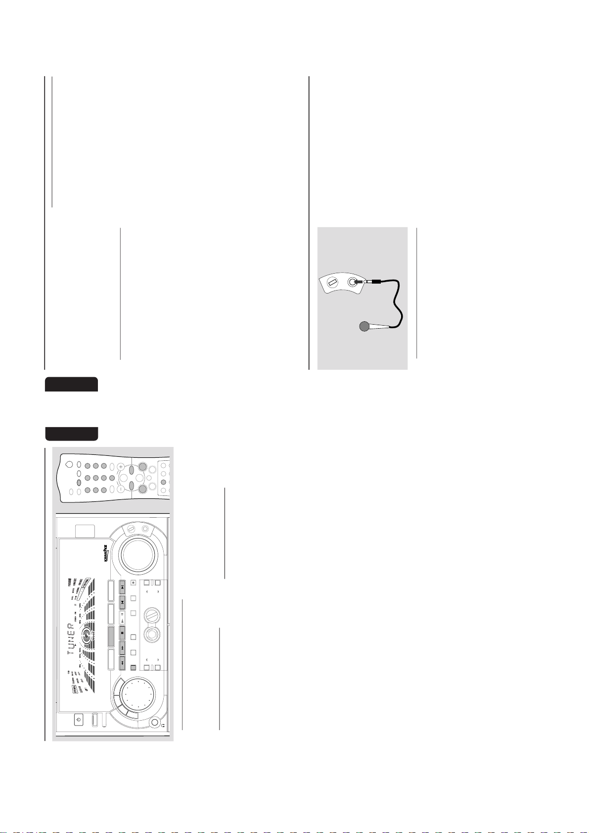
Microphone Mixing
Connect a microphone (not supplied) to the
system allowing you to sing along with the music
source.1Connect a microphone to the MIC jack.
● Before connecting the microphone, set the MIC
LEVEL to the minimum level to prevent
howling sound.
MIC LEVEL
2
Press CD, TUNER, TAPE or AUX to select
the source to be mixed and start playback.3Adjust the volume level of the source with
VOLUME control.4Adjust the microphone volume with MIC
LEVEL control.
Note:
–Keep the microphone away from the speakers to
prevent howling.
For Recording, please refer to “Tape
Operation/Recording”.
Karaoke
2-9
21
English
Ta pe Operation/Recording
M N H F SYSTEM
DUB
(HSD)
RECORD
DM
CLOCK/
TMER
PROG
V
O
L
U
M
E
STOP•CLEAR
SEARCH•TUNNG PLAY PAUSE
PREV NEXTS DE
PRESET
▲
▲
R SENSOR
AUTO
REVERSE
ECO POWER
DEMO STOP
JOG CONTROL
STANDBY-ON
OPEN
OPEN
BASS
TREBLE
B
A
S
S
/
T
R
E
B
L
E
1
3
DSC
BASS
1
3
2
4
6
5
7
9
8
VOLUME
á
à
2
ë
í
Ç
0
2
AUX/CDR
MUTE
CD 123
TUNER TAPE 1/2
AUTO REVCLOCK
SHUFFLE
PERSONAL
BASS/TREBLE
DM PROGRAM
REPEAT
TREBLE
+
-
CD
DRECT
VEC
TMER ON/OFF SLEEP
WOOX
WOOX LEVEL
+
-
ÅÉ
P
E
R
S
O
N
A
L
D
S
C
V
E
C
TAPE 1•2
CD 1•2•3
BAND
CDR/DVD
TAPE
CD
TUNER
AUX
wOOx
DYNAMC AMPL F CAT ON CONTROL
ON•OFF
LEVEL
MC LEVEL
IMPORTANT!
– Before playing a tape , check and tighten
slack tape with a pencil. Slack tape may get
jammed or may burst in the mechanism.
– C-120 tape is extremely thin and is easily
deformed or damaged. It is not
recommended for use in this system.
– Store the tapes at room temperature and
do not put them too close to a magnetic
field (for example, a transformer, TV or
speaker).
Ta pe Playback
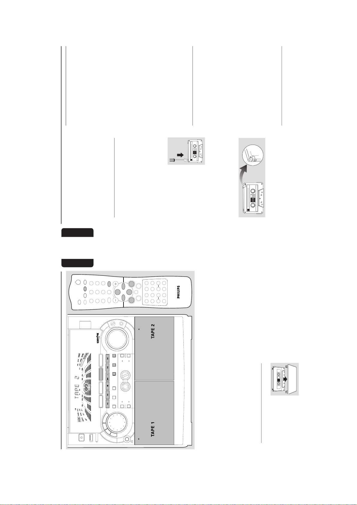
1
Press # OPEN to open the
tape deck door.2Insert a recorded tape and
close the tape door.
● Load the tape with the open
side down and the full spool
to the left.
3
Press TAPE (TAPE 1•2) repeatedly to select
tape deck 1 or tape deck 2.
➜ The selected tape deck number is displayed.4Press PLAYÉÅ to star t playback.
To stop playback
● Press Ç.
To change the playback side on tape
deck 2 only
● Press í or ë.
➜ The A (BACK) or B (FRONT) appear on
the display, depending on the tape side selected.
To change the playback mode on tape
deck 2 only
● Press AUTO REVERSE repeatedly to select
the different playback modes.
å : playback on one side of the tape only.
∂ : both sides are played once.
∫ : both sides are played repeatedly, up
to 10 times each side unless you pressÇ.
To rewind or fast forward during
playback
● Press and hold à or á until the desired
passage is reached, then release.
➜ The tape continues playing.
● The tape will stop automatically at the end of
the rewinding or fast forwarding.
➜ During searching,
the sound is reduced to a
low volume.
22
English
To rewind or fast forward when playback
is stopped
1
Press à or á.2Press Ç when you reached the desired passage.
Note:
– During rewinding or fast forwarding of a tape, it
is also possible to select another source (CD,
TUNER or AUX, for example).
General Information on
Recording
● If you do not intend to record via the
microphone, unplug the microphone to avoid
accidental mixing with other recording source.
● For recording, use only tape of IEC type I
(normal tape) or IEC type II (Cr0
2
).
● The recording level is set automatically, regardless
of the position of the Volume, VEC, DSC and so
forth.
● The tape is secured at both ends
with leader tape. At the
beginning and end of the tape,
nothing will be recorded for six
to seven seconds.
● To prevent accidental recording,
break out the tab on the left
shoulder of the tape side you want to protect.
● If “CHECK TAPE” is displayed, the protection
tab has been broken. Put a piece of clear
adhesive tape over the opening. Do not cover
the Cr0
2
tape detection hole when covering the
tab opening.
IMPORTANT!
– Recording is permissible if copyright or
other rights of third parties are not
nfringed upon.
– Recording is possible only on tape deck 2.
Preparation for Recording
1
Press TAPE (TAPE 1•2) to select TAPE 2.2Load a recordable tape into tape deck 2.
3
Press í or ë to select the recording tape side.
➜ A appears on the display for the reverse side .
➜ B appears on the display for the forward side.4Press AUTO REVERSE repeatedly to select a
recording mode.
➜ å for recording on one side only.
➜
∂
∂ for recording on both sides.
5
Prepare the source to be recorded.
CD – load the disc(s).
TUNER – tune to the desired radio station.
TAPE – load the prerecorded tape into tape
deck 1 with the full spool to the left.
AUX – connect external equipment.
When recording is in progress
➜
REC
starts flashing.
● It is not possible to change tape side.
● It is not possible listen to another source except
for dubbing tapes.
● It is not possible to activate the timer function.
One Touch Recording/Recording
the mixed sound
1
Press CD, TUNER or AUX to select the
source.
● You can connect a microphone to record the
mixed sound in tape deck 2 (refer to “Karaoke -
Microphone Mixing”).
2
Start playback of the selected source.3Press RECORD to start recording.
To stop recording
● Press Ç.
Note:
– One Touch Recording is not possible in TAPE
mode, "
SELECT SOURCE
" will be displayed.
CD Synchro Recording
1
Press CD 1•2•3 to select the disc.
● Press í or ë (or Digits 0–9 on the remote
control) to select the desired track to start
recording.
● You can programme the tracks in the order you
want them to be recorded (refer to “CD
Operation - Programming the disc tracks”).
2
Press RECORD to start recording.
➜ The disc will star t playback automatically.
Ta pe Operation/Recording
2-10
23
English
Ta pe Operation/Recording
To select another track during recording
1
Press PA USEÉÅ to interrupt recording.
2
Pressí or ë (or Digits 0–9 on the remote
control) to select the desired track.3Press PLAYÉÅ to resume recording.
To stop recording
● Press Ç.
➜ Recording and disc playback will stop
simultaneously.
Dubbing Tapes
1
Load the prerecorded tape in tape deck 1.
● You can set the tape to the desired passage
where recording will start.2Press DUB (HSD) once for normal speed
dubbing or twice (within 2 seconds) for high
speed dubbing.
➜ Playing and recording will star t simultaneously.
➜ "NORMAL" (normal speed) or "FAST" (high
speed) will be displayed, followed by "DUB" with
an indication on the selected tape side direction.
➜ During high speed dubbing, the volume will
be reduced and
HSD
will appear on the display.
● Dubbing of tapes is possible on one side of the
tape only. To continue record on the reverse
side, at the end of side A, flip the tapes to side B
and repeat the procedure.
To stop dubbing
● Press Ç.
Notes:
– Only
å
mode is available during dubbing.
– Dubbing of tapes is possible only from tape
deck 1 to tape deck 2.
–To ensure good dubbing, use tapes of the same
length.
–You can listen to another source while dubbing.
– During tape dubbing, it is not possible to use the
microphone to record the mixed sound.
Digital Recording via Digital Out
For CD digital recording, please refer to the
instruction manuals for the CD recorder, digital
audio equipment and so forth.
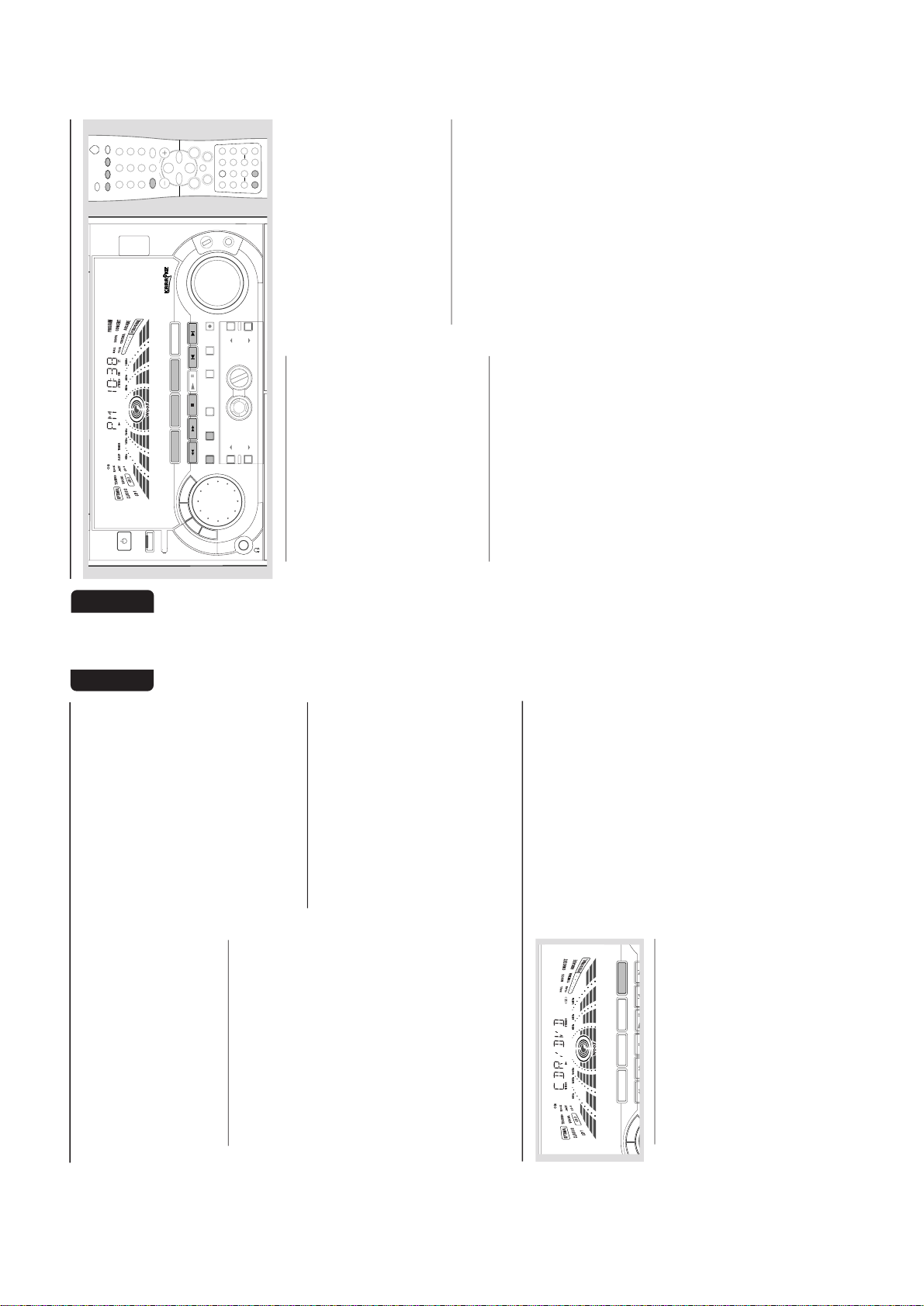
Listening to External Sources
1
Connect the audio out terminals of the external
equipment (TV, VCR, Laser Disc player, DVD
player or CD Recorder) to the AUX/CDR IN
terminals of your system.
2
Press AUX (CDR/DVD) repeatedly to select
CDR/DVD or normal AUX mode.
➜ "CDR/DVD" or "AUX" will be displayed.
M N H F SYSTEM
STOP•CLEAR
SEARCH•TUNNG PLAY PAUSE
PREV NEXTS DE
PRESET
▲
▲
DEMO STOP
B
A
S
S
/
T
R
E
B
E
V
E
C
TAPE 1•2
CD 1•2•3
BAND
CDR/DVD
TAPE
CD
TUNER
AUX
External Sources
● When CDR/DVD mode is selected, any audio
equipment connected to the LINE OUT
terminals of this mini system will be muted. You
will not be able to record or listen to the sound
from the LINE OUT source.
● If the sound from the external source is
distorted, select CDR/DVD mode for listening.
Notes:
–You are advised not to listen to and record from
the same source simultaneously.
– All the interactive sound control features (DSC or
VEC, for example) are available for selection.
– Refer to the operating instructions for the
connected equipment for details.
For Recording, please refer to “Tape
Operation/Recording”.
24
English
Clock/Timer
M N H F SYSTEM
DUB
(HSD)
RECORD
DM
CLOCK/
TMER
PROG
V
O
L
U
M
E
STOP•CLEAR
SEARCH•TUNNG PLAY PAUSE
PREV NEXTS DE
PRESET
▲
▲
BASS
TREBLE
B
A
S
S
/
T
R
E
B
E
P
E
R
S
O
N
A
L
D
S
C
V
E
C
TAPE 1•2
CD 1•2•3
BAND
CDR/DVD
TAPE
CD
TUNER
AUX
R SENSOR
AUTO
REVERSE
ECO POWER
DEMO STOP
JOG CONTROL
STANDBY-ON
wOOx
DYNAMC AMPL F CAT ON CONTROL
ON•OFF
LEVEL
1
3
DSC
BASS
ÅÉ
1
3
2
4
6
5
7
9
8
OLUME
á
à
2
ë
í
Ç
0
2
AUX/CDR
MUTE
CD 1 3
TUNER TAPE /2
AUTO REVCLOCK
SHUFLE
PERSONAL
BASS/TRBLE
DM PROGRAM
R PEAT
TREBLE
+
-
CD
DRECT
VEC
TMER ON/OFFSLE P
WOOX
WOOX LEVEL
+
-
MC LEVEL
View Clock
The clock (if it is set) will be shown in Standby
mode.
To view the clock in any source mode
(CD or TUNER for example)
● Press CLOCK/TIMER briefly (or CLOCK on
the remote control).
➜ The clock will be displayed for a few seconds.
➜ If the clock has not been set, "--:--" will be
displayed.
Note:
– When in Eco Power Standby mode, the clock will
not be displayed.
Clock Setting
The clock can be set in either 12-hour or
24-hour mode ("AM 12:00" or "00:00" for
example)
1
Press CLOCK/TIMER twice.2Press PROG on the system repeatedly to select
clock mode.
➜ If 12-hour mode is selected, "AM 12:00" will
start flashing.
➜ If 24-hour mode is selected, "00:00" will start
flashing.
3
Press à or á on the system repeatedly to set
the hour.4Press í or ë on the system repeatedly to set
the minute.5Press CLOCK/TIMER again to store the
setting.
➜ The clock will star t working.
To exit without storing the setting
● Press Çon the system.
Notes:
– The clock setting will be cancelled when the
power cord is disconnected or if a power failure
occurs.
– When in Eco Power Standby mode, the clock/
timer function will not operate.
– During clock setting, if no button is pressed
within 90 seconds, the system will exit clock setting
mode automatically.
Timer Setting
The system can switch on to CD, TUNER, or
TAPE 2 mode automatically at a preset time,
serving as an alarm to wake you up.
IMPORTANT!
– Before setting the timer, ensure that the
clock is set correctly.
– The timer will always be switched on
after it has been set.
– The timer will not star t if a recording is in
progress.
– The volume of the timer will increase
gradually from the minimum level until it
reaches the last tuned volume level.
1
Press and hold CLOCK/TIMER for more than
two seconds to select timer mode.
➜ "AM 12:00" or "00:00" or the last timer
setting will start flashing.
➜
TIMER
will start flashing.
➜ The selected source will be lighted while
other availab
le sources are flashing.
2-11
25
English
2
Press CD, TUNER or TAPE to select the
desired source.
● Make sure the music source has been prepared.
CD – Load the disc(s). To star t from a specific
track, make a programme (refer to “CD
Operation - Programming the disc tracks”).
TUNER – tune to the desired radio station.
TAPE – load the prerecorded tape into tape
deck 2.
3
Press à or á on the system repeatedly to set
the hour for the timer to start.4Press í or ë on the system repeatedly to set
the minute for the timer to start.5Press CLOCK/TIMER to store the start time.
➜ The timer is now set and activated.
➜
TIMER
will remain on the display.
● At the preset time , the selected source will play.
To exit without storing the setting
● Press Çon the system.
Notes:
– If the selected source (CD or TAPE) is not
available when preset timer is reached, TUNER will
be selected automatically.
– During timer setting, if no button is pressed
within 90 seconds, the system will exit timer setting
mode automatically.
To deactivate the TIMER
● Press TIMER ON/OFF on the remote control.
➜ The display will show "CANCEL" and
TIMER
will disappear from the display.
To activate the TIMER
● Press TIMER ON/OFF on the remote control.
➜ The last set timer information will be shown
for a few seconds and
TIMER
will appear on the
display.
Sleep Timer Setting
The sleep timer enables the system to switch to
Standby mode automatically at a preset time.1Set the clock (refer to “Clock Setting”).
2
Press SLEEP on the remote control repeatedly
to select a preset time.
➜ The selections are as follows (time in
minutes):
60 ™ 45 ™ 30 ™ 15 ™ OFF ™ 60 …
➜ "SLEEP XX" or "OFF" will be displayed. "XX"
is the time in minutes.
3
When you reach the desired length of time, stop
pressing the SLEEP button.
➜ The Sleep Timer is now set. After this
amount of time passes, the system will switch to
Standby mode.
To deactivate the Sleep Timer
● Press SLEEP repeatedly until "OFF" is displayed,
or press the STANDBY ON button.
Clock/Timer
27
English
Maintenance
Cleaning the Cabinet
● Use a soft cloth slightly moistened with a mild
detergent solution. Do not use a solution
containing alcohol, spirits, ammonia or abrasives.
Cleaning Discs
● When a disc becomes dir ty,
clean it with a cleaning cloth.
Wipe the disc from the centre
out. Do not wipe in circular
motion.
● Do not use solvents such as
benzine, thinner, commercially
available cleaners, or antistatic spray intended for
analogue records.
Cleaning the disc lens
● After prolonged use, dir t or dust may
accumulate at the disc lens. To ensure good
playback quality, clean the disc lens with Philips
CD Lens Cleaner or any commercially available
cleaner. Follow the instructions supplied with
cleaner.
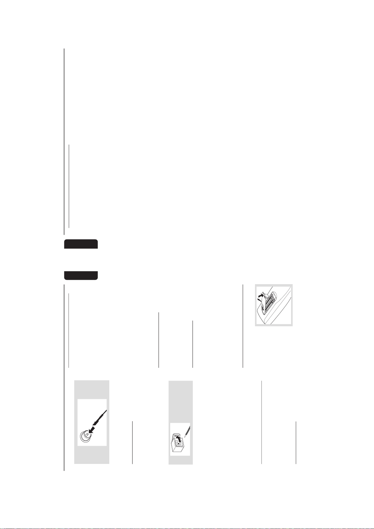
Cleaning the Heads and the Tape Paths
● To ensure good recording and playback quality,
clean the heads
A
, the capstan(s)
B
, and
pressure roller(s)
C
after every 50 hours of
tape operation.
● Use a cotton swab slightly moistened with
cleaning fluid or alcohol.
● You also can clean the heads by playing a
cleaning tape once.
C CB
B
A
Demagnetising the heads
● Use a demagnetising tape available at your
dealer.
Troubleshooting
WARNING
Under no c rcumstances should you try to repair the system yourself, as this will invalidate the
warranty. Do not open the system as there is a risk of electric shock.
If a fault occurs, first check the points listed below before taking the system for repair. If you
are unable to remedy a problem by following these h nts, consult your dealer or service centre.
Problem Solution
CD OPERATION
“NO DISC” is displayed. – Inser t a disc.
– Check if the disc is inser ted upside down.
–Wait until the moisture condensation at the lens
has cleared.
– Replace or clean the disc, see “Maintenance”.
“DISC NOT FINALIZED” is displayed. – Use a finalised CD-R(W) or CD-R.

2-12
28
English
Tr oubleshooting
RADIO RECEPTION
Radio reception is poor. – If the signal is too weak, adjust the antenna or
connect an external antenna for better reception.
– Increase the distance between the Mini HiFi
System and your TV or VCR.
TAPE OPERATION/RECORDING
Recording or playback cannot be made. – Clean deck parts, see “Maintenance”.
– Use only NORMAL (IEC I) or IEC type II (Cr0
2
)
tape.
– Apply a piece of adhesive tape over the missing
tab space.
The tape deck door cannot open. – Remove and reconnect the AC power plug and
switch on the system again.
GENERAL
The system does not react when buttons – Remove and reconnect the AC power plug and
are pressed. switch on the system again.
Sound cannot be heard or is of poor – Adjust the volume.
quality. – Disconnect the headphones.
– Check that the speakers are connected correctly.
– Check if the stripped speaker wire is clamped.
The left and right sound outputs are – Check the speaker connections and location.
reversed.
The remote control does not function – Select the source (CD or TUNER, for example)
properly. before pressing the function button (É,í,ë).
– Reduce the distance between the remote control
and the system.
– Inser t the batteries with their polarities
(+/– signs) aligned as indicated.
– Replace the batteries.
–Point the remote control in the direction of the
system’s IR sensor.
The timer is not working. – Set the clock correctly.
– Press TIMER ON/OFF to switch on the timer.
– If recording is in progress, stop recording.
Not all lighted buttons are showing light. – Press DIM to select DIM OFF display mode.
The Clock/Timer setting is erased. –Power has been interrupted or the power cord
has been disconnected. Reset the clock/timer.
The system displays features – Press and hold DEMO STOP Çon the system
automatically and buttons start flashing. to switch off the demonstration.
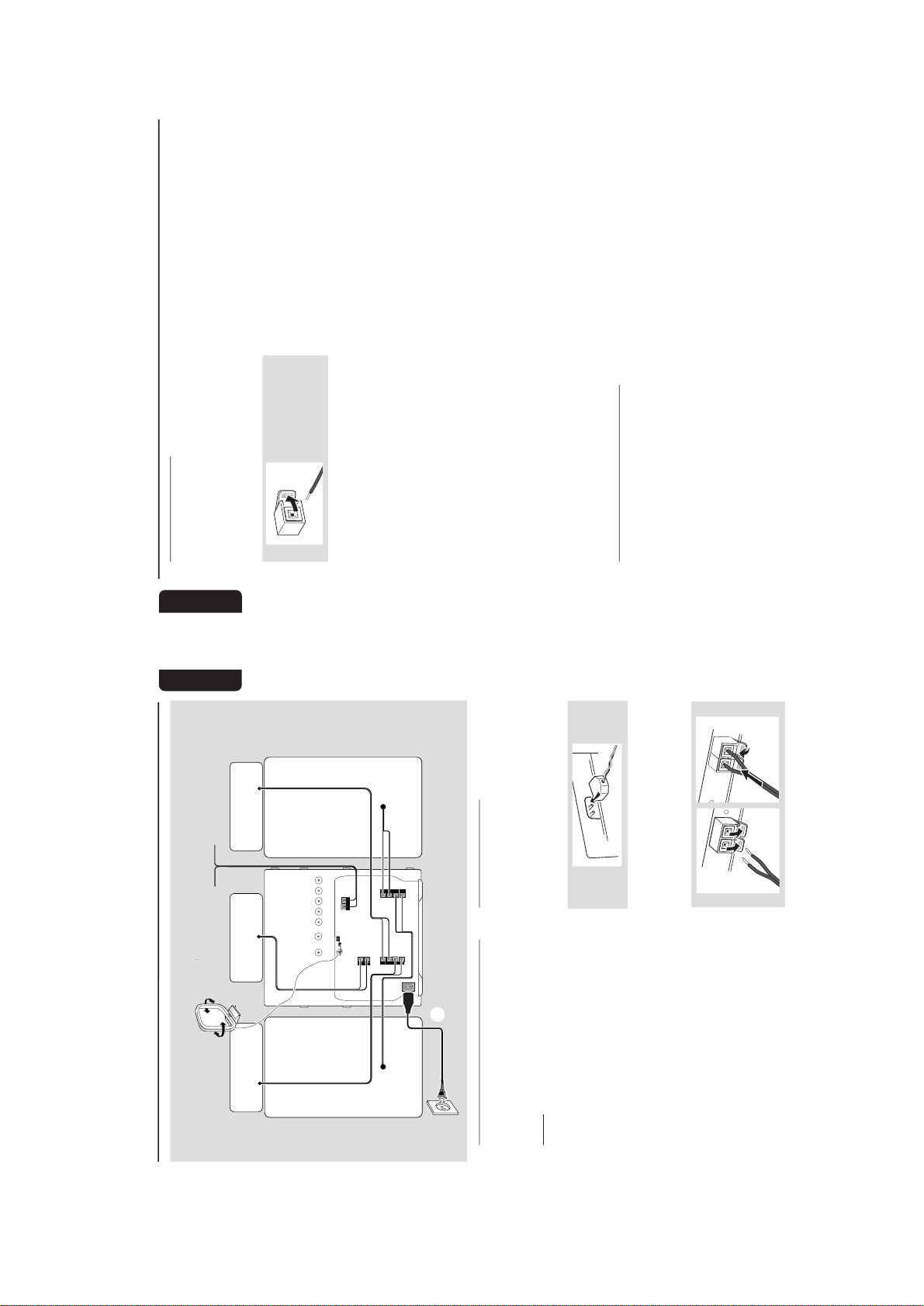
2-13
English
Preparations
Rear Connections
The type plate is located at the rear of the
system.APowe r
Before connecting the AC power cord to the
wall outlet, ensure that all other connections
have been made.
WARNING!
–For optimal performance, use only the
original power cable.
–Never make or change any connections
with the power switched on.
To avoid overheating of the system, a safety
c rcuit has been bui t in. Therefore , your
system may sw tch to Standby mode
automatically under extreme conditions. If
this happens, let the system cool down
before reusing t (not available for all versions).
B
Antennas Connection
Connect the supplied AM loop antenna and FM
antenna to the respective terminals. Adjust the
position of the antenna for optimal reception.
AM Antenna
● Position the antenna as far as possible from a TV,
VCR or other radiation source.
FM Antenna
1
2
● For better FM stereo reception, connect an
outdoor FM antenna to the FM
ANTENNA
terminal.
AM ANTENNA
AUXCDR N
SUB-
WOOFER
OUT
DG TAL
OUT
LNE OUT
LRLR
AC
MANS
REAR
SURROUND
L
+
–
R
–
+
FRONT
speaker
(right)
L
+
R
–
+
SURROUND
OUT
FM ANTENNA 300Ω
CENTER
center speaker
+
–
A
speaker
(left)
left
surround
right
surround
AM loop antenna
FM wire antenna
AC power cord
B
C
Additional Features For FW-P880/37
English
Preparations
C
Speakers Connection
Front Speakers
Connect the speaker wires to the SPEAKERS
(FRONT) terminals, right speaker to "R" and left
speaker to "L", colored (marked) wire to "+"
and black (unmarked) wire to "-".
1
● Clip the stripped portion of the speaker wire as
shown.
Rear Surround Speakers
Connect the speaker wires to the REAR
SURROUND terminals, right speaker to "R" and
left speaker to "L", colored (marked) wire to
"+" and black (unmarked) wire to "-".
Center Speaker
Connect the speaker wires to the CENTER
terminal, colored (marked) wire to "+" and
black (unmarked) wire to "-".
Notes:
–For optimal sound performance, use the
supplied speakers.
– Do not connect more than one speaker to any
one pair of
+
/
-
speaker terminals.
– Do not connect speakers with an impedance
lower than the speakers supplied. Please refer to
the SPECIFICATIONS section of this manual.
Wireless Surround Out Connection
Connect the transmitter unit of wireless rear
speakers to the SURROUND OUT terminal.
Note:
– The availability of a wireless transmitter and its
peripherals are subjected to the approval of local
authorities. Please check with your respective local
safety or approving authority.
Additional Features For FW-P880/37
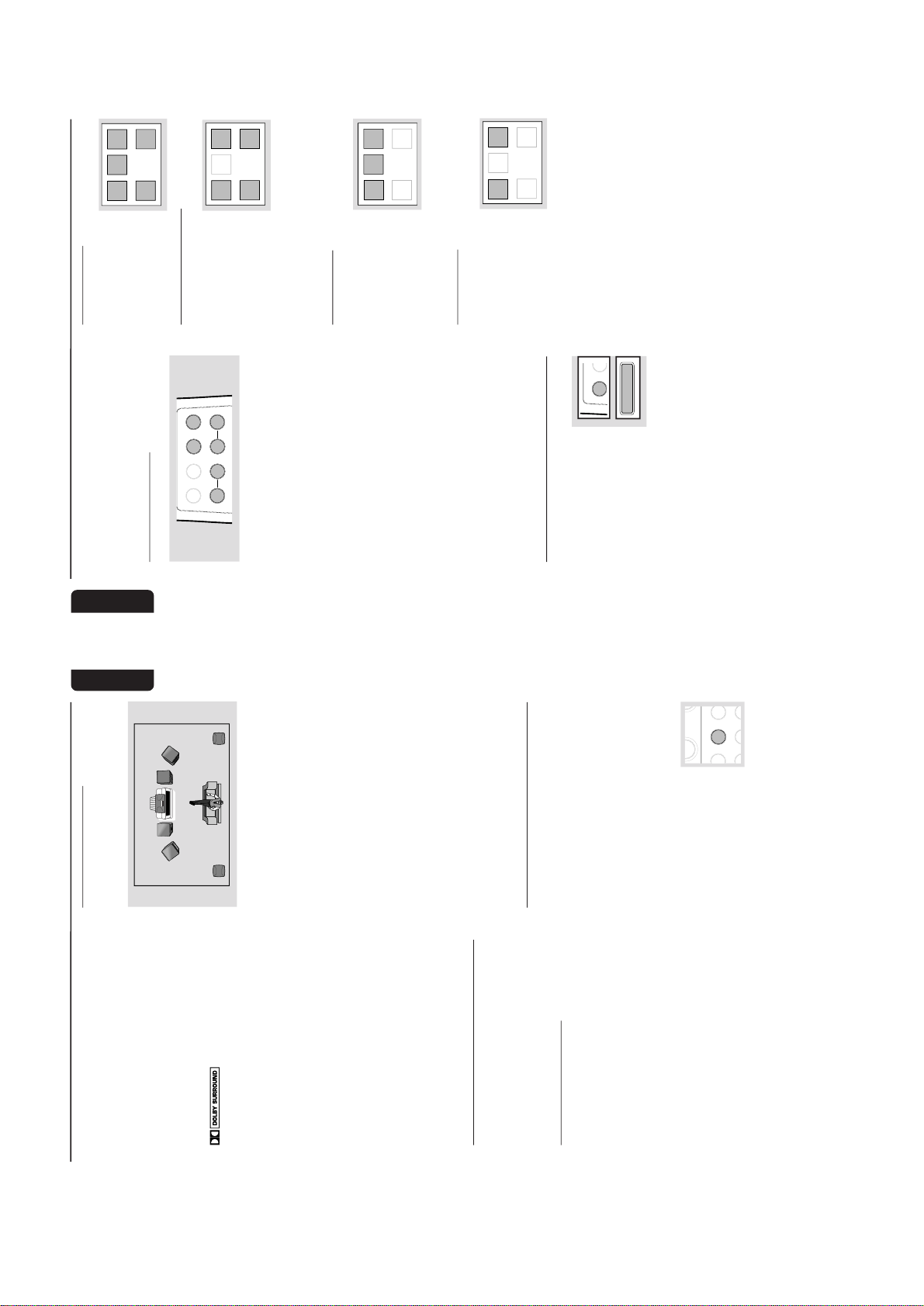
2-14
English
Dolby ProLogic Surround Sound provides the
current industry standard for home cinema
sound from VCR and TV broadcasts. The front
left and right speakers deliver detailed, directional
sound as the center speaker "steers" dialogue/
vocal sound and center screen action toward the
TV screen. Both surround speakers add a
greater sense of depth with special effects.
Audio and video tapes and discs with the
Dolby Surround mark are
encoded for multi channel Dolby Surround
sound. The DOLBY PRO LOGIC sound setting
allows you to listen to audio tracks as they were
recorded through the left, right, center, and rear
channels.
IMPORTANT!
– Dolby Pro Logic Surround sound can only
be reproduced if the program is broadcast
in Dolby Surround Sound.
–For the best Dolby Pro Logic sound,
sw tch on DPL w th DSC set to “Classic”
and with VEC off.
– Dolby Pro Logic mode will automatically
sw tch to normal Stereo mode when
headphones is connected.
– When recording, switch to normal stereo
mode.
Setting up the Dolby Pro Logic
system
You must set up the system properly in order to
experience and enjoy a Home Cinema sound
ambience.
Connecting the Speakers
5-Speakers Connection (refer to
“Preparations - Rear Connections”)
● Front speakers: Connect the front speakers.
● Center speaker : Connect the center speaker.
● Rear (surround) speakers: Connect either the
wired rear surround speakers or a pair of
wireless rear speakers (not supplied) to the
SURROUND OUT terminals.
Positioning the Speakers
To get the best surround sound effect, place the
speakers as follows.
TV
CENTER
SPEAKER
SURROUND
RIGHT
SURROUND
LEFT
FRONT
LEFT
FRONT
RIGHT
MINI HIFI
SYSTEM
SUB-
WOOFER
Front Left and Right Speakers
For the best sound, place the left and right
speakers at an angle of approximately 45
degrees to the listener.
Note:
–To avoid magnetic interference with the picture
on your TV, do not position the front speakers too
close to the TV.
Rear (surround) Speakers
The surround speakers should be placed at
normal listening ear level or mounted on the
wall at the back of the room. Most importantly,
experiment when placing the surround speakers
to obtain the best sound.
Center Speaker
For the best sound, place the center speaker at
the same height as the left and right speakers.
Place the center speaker directly above or
beneath the television.
Te st Tone
This feature enables you to adjust the Front Left,
Front Right, Center and Surround Sound levels
of the respective speakers in Dolby Pro Logic
mode.
You must sit at the ideal sitting position and
use the remote control to perform this
operation.
1
Press CD, TUNER, TAPE or AUX to switch
on the system.
2
Press TEST TONE on the
remote control.
➜ A test signal is generated; it
will move through the Left,
Center, Right, and Sur
round
speakers.
Dolby Pro Logic
BA
CENTER
R
S
REPEAT
L
+
Additional Features For FW-P880/37
English
➜ "TEST TONE" followed by "ADAPT
BALANCE, CENTER AND REAR LEVEL" will
be displayed.
➜ The test signal will last for about 90 seconds.
Adjust the sound level
BALANCE
CENTER
REAR
DPL TEST TONE
LR
+
-
+
-
Front speakers
● Press BALANCE L on the remote control for
left speaker and press BALANCE R on the
remote control for right speaker.
➜ "BAL L +XX" or "BAL R +XX" will be
displayed.
Center speaker
● Press CENTER + or - on the remote
control.
➜ "CENT +XX" or "CENT-XX" will be displayed.
Surround speakers
● Press REAR + or - on the remote control.
➜ "REAR +XX" or "REAR -XX" will be
displayed.
To switch off the TEST TONE
● Press TEST TONE.
Notes:
– It is advisable to set the speakers’ level at
normal listening level.
–"
XX
" denotes the sound level.
Switching the Dolby Pro Logic
● Press DPL (PRO LOGIC)
repeatedly to select and cycle
through the various sound
modes.
➜ The Dolby Pro Logic display
panel will light up with the
selection.
Dolby Surround ➜ Dolby Center Phantom
➜ Dolby 3 Stereo ➜ Stereo ➜ Dolby
Surround …
Dolby Surround
This setting is for a full
Dolby Surround Pro Logic
mode.
➜ “DOLBY SURROUND”
will be displayed.
Dolby Center Phantom
This setting is for use
without the center speaker.
It redistributes the center
speaker sound to the left
and right speakers,
providing conventional
stereo across the front.
➜ “ DOLBY CENTER PHANTOM” will be
displayed.
Dolby 3 Stereo
Use this setting when full
surround is not required,
but a wide stereo sound is
desired. It requires only the
left, right and center
speakers.
➜ “ DOLBY 3 STEREO” will be displayed.
Normal Stereo
This setting is for normal
stereo sound without
Dolby Pro Logic. It requires
only the left and r
ight
speakers.
➜ “STEREO” will be
displayed.
Dolby Pro Logic
LEFT CE NTER RIGHT
SURR
SURR
LEFT CE NTER
RIGHT
SURR
SURR
LEFT CENT ER RIGHT
SURR
SURR
LEFT CE NTER
RIGHT
SURR
SURR
DPL TEST T
PRO LOGIC
Additional Features For FW-P880/37

3-1 3-1
DISMANTLING INSTRUCTIONS
Dismantling of the Cassette Cover
2. Twist screw driver
3. Lift up and out
Dismantling of the CDC Module and Front Panel
3) Remove the Cover Tray CDC (pos 106) as indicated.
1. Place screw driver
(flat side) between
the cassette cover
& cassette door
Remove Cover Tray CDC
Remove Cassette Cover
Dismantling of the CDC Module and Front Panel
1) Loosen 16 screws to remove the Cabinet Rear (pos 259)
of the set :-
-5 screws each on the left side & right side of the
Cabinet Rear.
-6 screws at the rear of the Cabinet Rear.
2) Slide out the CDC Tray as shown in the diagram below with
the help of a flat head screw driver.
Cassette Cover
4) Loosen 2 screws A and 2 screws B to remove the CDC
Module (pos 1104) as indicated.
5) Remove 1 screw (pos 305) at the bottom to separate the
Front Panel Assembly from the Plate Bottom (pos 236).
Front View CDC
Sliding Out The CDC Tray
Remove CDC Module

3-2
3-2
Dismantling of the Front Board
1) Uncatch C as indicated to loosen the Dolby Pro Logic
Board (pos 1108) for set with DPL.
2) Remove 1 screw D as indicated to loosen the Headphone
Board (pos 1100-E).
3) For set with DPL
Remove 5 screws E as indicated to loosen the Plate
Front (pos 254) and 4 screws F as indicated to loosen the
Front Board (pos 1100-A).
For set without DPL
Remove 5 screws E and 4 screws F as indicated to
loosen the Front Board (pos 1100-A).
4) Remove 5 screws H as indicated to loosen the Control
Board (pos 1100-B).
5) Remove 1 screw Q as indicated to loosen the Blue Strip
LED Board (pos 1100-F).
Dismantling of Rear Portion
1) Remove 5 screws J as indicated to loosen the AF Board
(pos 1101).
2) Remove 4 screws K and uncatch M1 as indicated to
loosen the Tuner Board (pos 1102).
3) Remove 3 screws L and 1 screw N (if obstructed) and
uncatch M2 as indicated to take out the Plate Rear (pos
234).
4) Remove 2 screws P to free the Power Module (pos 1 105)
from the Bottom Plate assembly.
Remove Dolby Pro Logic (DPL) Board
AF Board Top View
Remove Control and Blue Strip LED Boards
Dismantling of the ETF Tape Module
1) Remove 6 screws G as indicated to loosen the ETF T ape
Module (pos 1103).
Repair Hints
1) The Knob Volume Rotary (pos 149) can be remove by
inserting a strong string into the slot and pull it out in the
direction as indicated. See picture 1.
2) The Knob Jog Rotary (pos 138) can be remove by
inserting a strong string into the slot and pull it out in the
direction as indicated. See picture 2.
Picture 1
Picture 2

3-3 3-3
Repair Hints
3) During repair it is possible to disconnect the Tuner board
and CDC Module completely unless the fault is suspected to be in that area. This will not affect the
performance of the rest of the set.
4) Due to the short flex cable wires in the ETF Module, the
pc board should be disconnected and reconnected on
the reverse side of the tape mechanism to keep it
electrically connected during repair. See picture 3.
Note: The flex cables are very fragile, care should be taken
not to damage them during repair. After repair, be
very sure that the flex cables are inserted properly
into the flex sockets before encasing, otherwise faults
may occurs.
Picture 3
Service pos B
Use a insulation sheet to prevent
the AF board from being damaged
or short-circuit to any metal parts.
Service pos CService pos A
Use a insulation sheet to prevent
the ETF board from being damaged
or short-circuit to any metal parts.
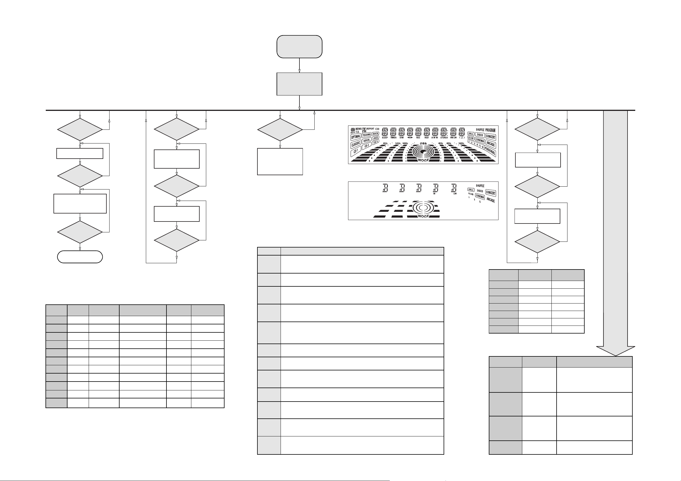
3-4 3-4
SERVICE TEST PROGRAM
"EAS"
QUARTZ
TEST
O
Button pressed?
Y
Display shows
32K
Output at (Front Board)
pin 19 of uP = 2048Hz
O
Button pressed?
Y
Display shows
12M
Output at (Front Board)
pin 19 of uP = 2,929.6875Hz
9
Button pressed?
Y
USA
"USA"
87.5MHz
108MHz
530kHz
1700kHz
560kHz
1500kHz
98MHz
87.5MHz
87.5MHz
87.5MHz
87.5MHz
TUNER
TEST
TUNER
Button pressed?
Y
Display Tuner Version
"ccc"
TUNER
Button pressed?
Service frequencies are
copied to the RAM (see Table 1)
Tuner works normally except:
PROGRAM button
Disconnect
Mains cord ?
Y
Service Mode left
PRESET
Europe
"EUR"
1
87.5MHz
2
108MHz
3
531kHz
4
1602kHz
5
558kHz
6
1494kHz
7
153kHz
8
279kHz
9
198kHz
10
11
98MHz
87.5MHz
Note: * Depending on the selected grid frequency (9 or 10kHz)
By holding the TUNER and R buttons depressed while switching on the Mains supply, one
of the undermentioned features will be activated:
- the tuning grid frequency is toggled between 9kHz and 10kHz for the Oversea (/21) version.
- the extended FM1 (65.81MHz - 74MHz) is toggled on and off for East Eur. (/34) version.
N
N
N
East Eur.
"EAS"
87.5MHz
108MHz
531kHz
1602kHz
558kHz
1494kHz
87.5MHz
87.5MHz
87.5MHz
87.5MHz
98MHz
East Eur. Extended-band
65.81MHz
108MHz
74MHz
87.5MHz
531kHz
1602kHz
558kHz
1494kHz
98MHz
70.01MHz
65.81MHz
Table 1
N
N
N
Oversea
"OSE"
87.5MHz
108MHz
531/530kHz*
1602/1700kHz*
558/560kHz*
1494/1500kHz*
87.5/98MHz*
87.5MHz
87.5MHz
87.5MHz
98/87.5MHz*
To start service test program
hold
depressed while
plugging in the mains cord
Display shows the
ROM version
"S-Vyy"
(Main menu)
SERVICE
PLAY MODE
POWER
Button pressed?
Y
Set is in Service PLAY Mode.
In case of failures, error
codes according to Table 2
will be displayed.
The Service Play Mode is intended to
detect and identify the failures in the CD Mode.
In this mode the electronics will still function
even when an error is detected so that
repair activities can be carried out.
Error code
E1000
E1001
E1002
E1003
E1005
E1006
E1007
E1008
E1020
E1070
E1071
E1079
Error Description
Focus Error
Triggered when the focus could not be found within a certain time when starting up the CD
or when the focus is lost for a certain time during play.
Radial Error
Triggered when the radial servo is off-track for a certain time during play.
Sledge In Error
The sledge did not reach its inner position (inner-switch is still close) before approximately
6 Sec. have passed by. Inner-switch or sledge motor problem.
Sledge Out Error
The sledge did not come out of its inner position (inner-switch is still open) before approximately
250 mSec. have passed by. Inner-switch or sledge motor problem.
Jump-offtrack error
Triggered in normal play when the jump destination could not be found within a certain time.
When this error occurred, software will try to recover by initiating the jump command again.
If it is recoverable, the disc will continue to play.
Subcode Error
Triggered when a new subcode was missing for a certain time during play.
PLL Error
The Phase Lock Loop could not lock within a certain time.
Turntable Motor Error
Generated when the CD could not reached 75% of speed during startup within a certain time.
Discmotor problem.
Focus Search Error
The focus point has not been found within a certain time.
The carousel switch is not open within certain time. This can happen when either the switch is
defective and closed all the time, or when the carousel is blocked when located exactly at a
disc position.
The carousel position switch did not close within a certain time. This can happen when the
switch is defective and never closes electrically, or when the carousel is blocked in between
two disc positions. The time-out is approximately 5 Sec.
The drawer could not enter the inside position is opening again. This can be caused because
the drawer is blocked by something and cannot go fully inside, or the drawer switch is defective
and does not close.
™ & Aux
N
S refers to Service Mode
V refers to Version
yy refers to Software version number of the µProcessor
(counting up from 01 to 99)
Table 2
Figure 1
Figure 2
DISPLAY
TEST
2
Button pressed?
Y
Display shows Figure 1
and switch all LEDs on
2
Button pressed?
Y
Display shows Figure 2
and switch alternate LEDs on
(see Table 3)
9
Button pressed?
Y
LEDs
DISC 1
DISC 3
CD
TAPE
DECOR
DPL CENTRE
STEREO RIGHT
TEST
EEPROM TEST A test pattern will be sent to the EEPROM.
FW-C870
On
On
On
On
On
Table 3
Activated with
R
9 to Exit
TEST
ROTARY
ENCODER TEST
LEAVE SERVICE
TESTPROGRAM
QEEPROM FORMAT
Rotary Volume Knob
or
Rotary WOOX Knob
or
Jog Shuttle Knob
Disconnect
mains cord
N
N
N
FW-P880 , FW-P900
On
On
On
On
On
On
On
Various
other Tests
ACTION
"PASS" is displayed if the uProcessor read
back the test pattern correctly, otherwise
"ERROR" will be displayed.
Load default data. Display shows "NEW"
for 1 second.
Caution!
All presets from the customer will be lost!!
Display shows value for 2 seconds.
Values increases or decreases in steps of 1
until 0 (Min.) or 40 (Max.) is reached.
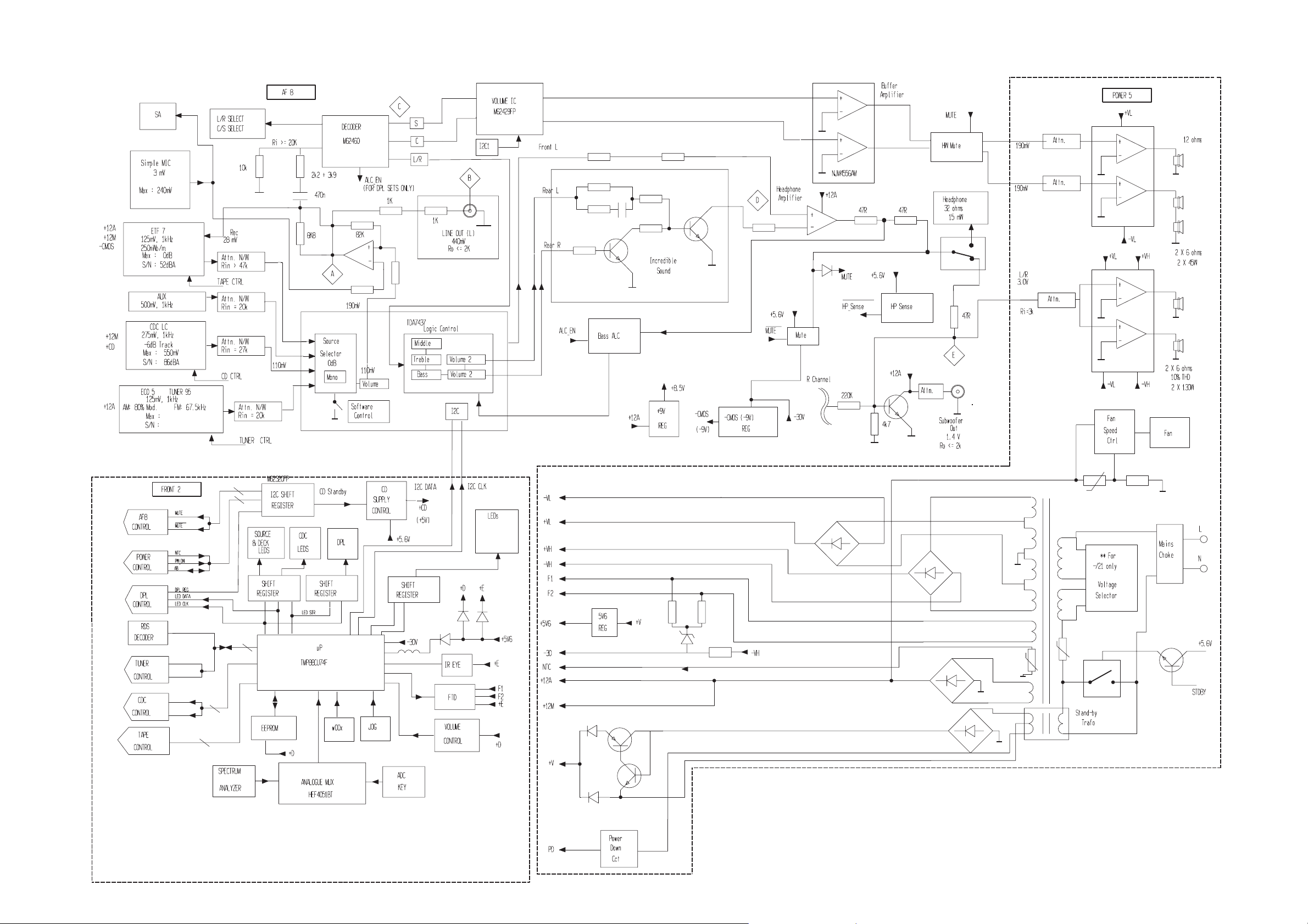
SET BLOCK DIAGRAM
4-1 4-1
(Blue Strip)
(wOOx)
(BassTreble)
PCS 103 615
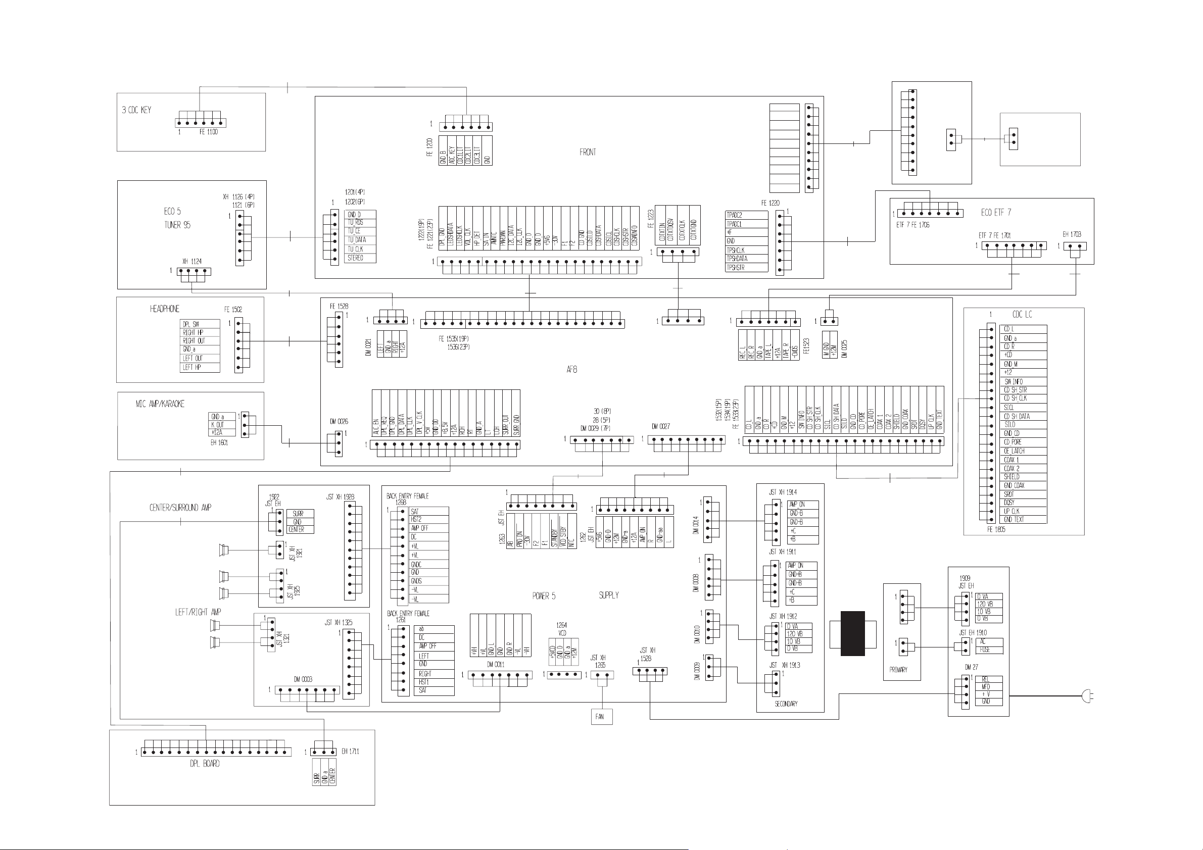
SET WIRING DIAGRAM
5-1
5-1
280
1561
140
1202
180
1204
340
280
1200(19P) (w/o DPL)
(23P) (with DPL)
1203 280
FE 1538
BlueStrip
WooXA
+5V6
WooXB
GND_B
KEY0
GND
KEY2
WooXLIT
BassTreble
FE 1224
1
1205
180
1208
180
FE 1400
1
CONTROL PANEL
EH 1420
1000
1000
180
1206 280 1565
Blue LED
220
1210
1207
140
340
1566
220
FE 1714
1573
280
1577
220
TRAFO
280
1201(19P)
(23P)
(w/o CD TEXT)
(with CD TEXT)
FE 1712
PCS 103 616
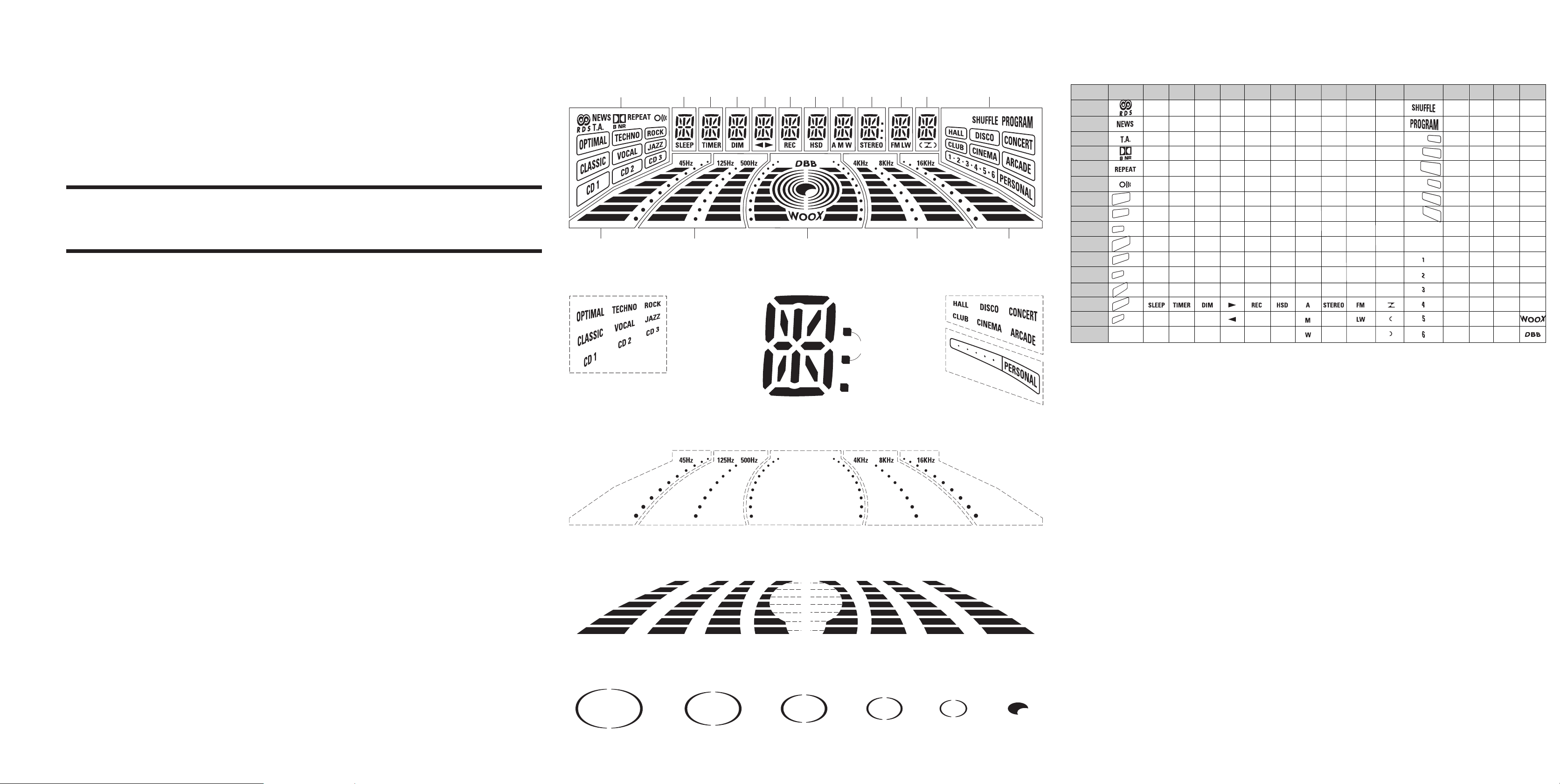
6-1
6-1
6-1
FRONT BOARD
FTD DISPLAY PIN CONNECTIONS
4G2G 6G5G 7G 8G 9G 11G 12G
1G
3G 10G
14G 13G
h j k
f
g
FTD DISPLAY PIN CONNECTIONS
1G
P1
P2
P3
P4
P5
P6
P7
P8
P9
16G 15G13G
a
b
m
col
S2
P10
P11
P12
P13
P14
P15
P16
S1
(OPTIMAL)
(TECHNO)
(ROCK)
(CLASSIC)
(VOCAL)
(JAZZ)
(CD 1)
(CD 2)
(CD 3)
2G
j , p
m
3G
4G
5G
6G
7G
8G
a
a
a
a
a
a
a
h
h
h
h
h
h
h
j , p
j , p
j , p
j , p
j , p
j , p
k
k
k
k
k
k
k
b
b
b
b
b
b
b
f
f
f
f
f
f
f
m
m
m
m
m
m
g
g
g
g
g
g
g
c
c
c
c
c
c
c
e
e
e
e
e
e
e
r
r
r
r
r
r
r
n
n
n
n
n
n
n
d
d
d
d
d
d
d
-
-
-
-
-
-
-
-
-
-
-
9G
j , p
m
col
Dp
10G
a
h
j , p
k
b
f
g
c
e
r
n
d
11G
a
h
j , p
k
b
f
m
g
c
e
r
n
d
-
m
12G
a
h
(HALL)
k
(DISCO)
b
(CONCERT)
f
(CLUB)
(CINEMA)
g
(ARCADE)
c
e
r
n
d
S2
S3
13G
B1
B2
B3
B4
B5
B6
B7
S4
B8
B9
B10
B11
B12
B13
B14
S5
14G
B1
B2
B3
B4
B5
B6
B7
S6
B8
B9
B10
B11
B12
B13
B14
15G
16G
B1
B1
B2
B2
B3
B3
B4
B4
B5
B5
B6
B6
B7
B7
S7
S8
B8
S9
B9
S10
B10
S11
B11
S12
B12
S13
B13
S14
B14
-
-
TABLE OF CONTENTS
FTD pin connection .........................................................6-1
Front Board - Component and Chip layouts ...................6-2
Front Board - Circuit diagram ..........................................6-3
Key-CDC part - Layouts & Circuit diagram .....................6-4
Headphone part - Layouts & Circuit diagram..................6-4
Karaoke part - Layouts & Circuit diagram .......................6-4
Control part - Layouts & Circuit diagram.........................6-5
Blue Strip LED part - Layouts & Circuit diagram.............6-5
Electrical parts list............................................................6-6
(1G)
S1
e
r p n
d
c
Dp
S3
(2G~11G) (12G)
S8S6 S7 S5S4
(13G) (14G) (16G) (15G) (13G)
B1
B2
B3
B7
B6
B5
B4
B4 B4
B3 B3
B2 B2
B1 B1
B7
B6
B5 B5
B14
B13 B13B13
B12 B12 B12
B11 B11 B11
B10 B10 B10
B9 B9 B9
B8 B8 B8
B7
B6
B5
B4
B3
B2
B1
B7 B14B14
B6
(13G) (14G) (16G)
(16G)
(15G) (13G)
S13 S14S12S11S10S9

6-2 6-2 6-2
FRONT BOARD - COMPONENT LAYOUT FRONT BOARD - CHIP LAYOUT
This assembly drawing shows a summary of all possible versions. For components used in a specific version see schematic diagram and respective parts list.
This assembly drawing shows a summary of all possible versions. For components used in a specific version see schematic diagram and respective parts list.
3139 113 3424 pt3 dd wk0035
Some location on this board is prepared for both 0603 & 0805 SMDs footprint, in such locations 0603 SMDs may be substituted.
3139 113 3424 pt3 dd wk0035
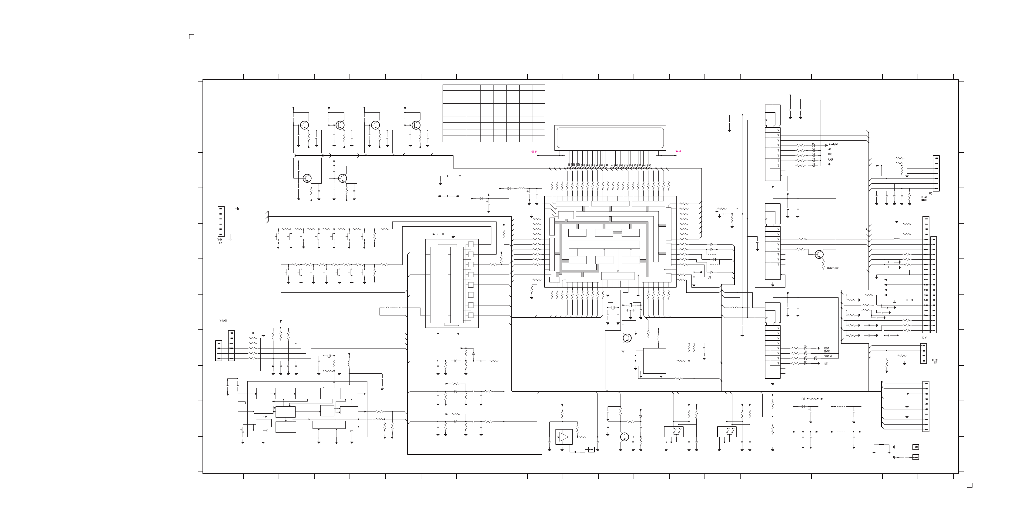
6-3
6-3
6-3
FRONT BOARD - CIRCUIT DIAGRAM
1200 D1
1201 H1
1202 G1
1203 E3
1204 E3
1205 E3
1206 E4
1207 E4
1208 E5
1209 E5
1210 F5
1211 F5
1212 F4
1213 F3
1214 F3
1215 F4
1216 F4
1217 B10
1218 J13
1219 J15
1220 C21
1221 D21
1222 E21
1223 H21
1224 I21
1225 C8
1226 D7
1227 D8
1902 K20
1903 K20
1904 K11
2200 B3
2201 B4
2202 B5
2204 B3
2205 B4
2206 B5
2208 B4
2209 B5
2210 B6
2212 C3
2213 C4
2216 D3
2217 D4
2220 D4
2221 D5
2225 H2
2226 I2
2227 I3
2228 I3
2229 I3
2230 I1
2231 I1
2232 J1
2233 J1
2234 H4
2236 I5
2237 E7
2238 H8
2239 I7
2240 I8
2241 I7
2242 I8
2243 J8
2244 J7
2245 J8
2246 D9
2247 D10
2248 D8
2249 G13
2250 G12
2251 G12
2252 G12
2253 G13
2254 F14
2255 H14
2256 A17
2257 B15
2258 D17
2259 D15
2260 J12
2261 J13
2262 K10
2263 K112235 H4
2264 K12
2265 K14
2266 K14
2267 K16
2268 K16
2269 D19
2270 D20
2271 D20
2272 D20
2273 F20
2274 F20
2275 G20
2276 G19
2277 H19
2278 H20
2279 J17
2280 J19
2281 K17
2282 K17
2283 K19
2284 K20
2285 K20
2286 A17
2287 D17
2288 G15
2289 G17
2290 G17
2291 C7
2292 B6
2293 D7
2294 B6
2296 B7
2297 J12
2298 G20
2299 G20
2300 G20
2301 K11
2302 E16
3200 B3
3201 B4
3202 B5
3204 D3
3205 D4
3208 E3
3209 E3
3210 E3
3211 E4
3212 E4
3213 E5
3214 E5
3215 E5
3216 F3
3217 F3
3218 F4
3219 F4
3220 F4
3221 F5
3223 F5
3224 H2
3225 H3
3226 H3
3227 H2
3228 H2
3229 H2
3230 H2
3231 H2
3232 H4
3233 I4
3234 J5
3235 J5
3236 J5
3237 J6
3238 H8
3239 H9
3240 I7
3241 I8
3242 I8
3243 I8
3244 I7
3245 I8
3246 J7
3247 J8
3248 J7
3249 J8
3250 D103222 F5
3251 E10
3252 E10
3253 E9
3254 E10
3255 E10
3256 E10
3257 E10
3258 E10
3259 F10
3260 F10
3261 F10
3262 F10
3263 C10
3264 C10
3265 C11
3266 C11
3267 C11
3268 C11
3269 C11
3270 C11
3271 C11
3272 C12
3273 C12
3274 C12
3275 C12
3276 C12
3277 C12
3278 C12
3279 C13
3280 C13
3281 C13
3282 C13
3283 C13
3284 C13
3285 C13
3286 C14
3287 G10
3288 G10
3289 G10
3290 G11
3291 G11
3292 G11
3293 G11
3294 G11
3295 G11
3296 G11
3297 G12
3298 G13
3299 G13
3300 G13
3301 G13
3302 G14
3303 H13
3304 D14
3305 D14
3306 D14
3307 D14
3308 D14
3309 E14
3310 E14
3311 E14
3312 E14
3313 E14
3314 E14
3315 E14
3316 F14
3317 F14
3318 F14
3320 H14
3321 H14
3322 H14
3323 I14
3324 B17
3325 B17
3326 C17
3327 C17
3328 C17
3329 D15
3330 E17
3331 H17
3332 H17
3333 H17
3334 H17
3335 J16
3336 J12
3337 J10
3338 J14
3339 J14
3340 J16
3341 J16
3342 J12
3343 J11
3344 J16
3345 J11
3346 K13
3347 C20
3348 C20
3351 C20
3352 D20
3353 E20
3354 E20
3355 E20
3356 F20
3357 F19
3358 G19
3359 G19
3360 G20
3361 G20
3362 G20
3363 H20
3364 H20
3367 G19
3368 G19
3369 G19
3370 H19
3371 E17
3372 F18
3373 F9
3374 F9
3376 B6
3377 D15
3378 D20
3379 I18
5200 H4
5201 H4
5202 G6
5203 G6
5204 C9
5205 G12
5206 G12
5207 H13
5208 G15
5209 E20
6201 J13
6203 H8
6204 H7
6205 I7
6206 J7
6207 D9
6208 D8
6209 E15
6210 E15
6211 E15
6212 F15
6213 F15
6214 B18
6215 B18
6216 C18
6217 C18
6218 C18
6220 H17
6222 H17
6223 H18
6224 H17
6225 H17
6226 J17
6227 I17
7200 B3
7201 B4
7202 B5
7204 A16
7205 C3
7206 C4
7209 D14
7210 D16
7211 E7
7212 H12
7213 H13
7214 I2
7215 J12
7216 K11
7217 E18
7218 G16
7220 B6
9300 J18
9301 J18
9310 E15
9311 F15
9312 J18
1 23456789101112 13 14 15 16 17 18 19 20 21
Variations table for Front Board
1 of 8
6204
6205
6206
1
1225
1201
IN USE
IN USE
IN USE
IN USE
-
IN USE
-
1
6208
+5V6
1N4003
Y0
Y1
Y2
Y3
Y4
Y5
Y6
Y7
Z
VEE
7
+D
3238
680K
6203
1N4148
2238
820p
47K
3241
2240
6n8
47K
3245
2243
47n
47K
3249
FW-C83/22
A
+D
+D
+D
+D
FW-C85/22/34
FW-C85/37
FW-C85/21
FW-C870/21
FW-P900/37
2202
2209
2u2
VDDD
11
2221
3213
150R
1208
100p
150R
1211
3221
GG13
GG16
100p
TUNER
GND-B
GND-B
QUAL
RDDA
RDCL
T57
100p
7202
BC847B
100p
2206
82K
3202
2210
G14
100p
GG14
2292
100p
7220
BC847B
100p
2294
82K
3376
2296
-30V
G1
3214
1K
3215
1209
+C
CD
3222
LEDShCLK
7211
HEF4051BT
A0
11
1K
A1
1210
3223
+C
2K7 2K7
Key0
5203
5202
10u
10u
MuxEnable
TU_CE
TU_DATA
10
LEDShDATA TpADC1
9
A2
VOL_CLK
E
6
TU_CLK
TU_STEREO
SA3
2236
100n
TuRDSCLK
10K
SA2
SA1
1
3234
2
16
15
TuRDSDATA
*
1K
3235
*
1K
10K
3237
3236
##
##
2201
2208
82K
2220
DPL
GND-B
3218
390R
1212
100p
@
GG12
GG15
100p
3211
270R
1206
POWER
GND-B
100p
7201
BC847B
2205
100p
82K
3201
-30V-30V -30V
G13
G16
+D
100p
2213
7206
BC847B
2217
100p
82K
3205
-30V
TAPE
AUX
3212
220R
1207
GND-B
GND-B
BASS/TREBLE
STANDBY
3220
3219
220R
270R
1216
1215
GND-B
GND-B
100p
2200
7200
BC847B
B
2204
100p
3200
82K
G12
G15
+D
C
D
1200
6
5
4
3
2
1
E
Cdc3Lit
Cdc2Lit
Cdc1Lit
GND-B
GND
DOLBY NR
3208
820R
1203
##
GND-B
PERSONAL
F
GND-B
GND-B
NEWS
1214
*
820R
3216
1204
3209
560R
2212
2216
DSC
GND-B
100p
100p
RDS
GND-B
1213
*
3217
560R
1205
-30V
3210
390R
7205
BC847B
3204
VEC
GND-B
G
+D
1202
*
1
2
1
3
2
H
I
4
3
5
4
6
##
1201
2230
J
2225
100p
*
3227 1K
*
1K
3228
1K
3229
3224
1K3230
3231 1K
2226
7214
*
SAA6579T
47p
2231
560p
**
560p
2232
*
2233
*
4
8
7
5
3
2u2
ANTI
MUX
ALIASING
FILTER
SCOUT
CLOCKED
CIN
COMPARATOR
VDDA
VREF
VP1
REFERENCE
VOLTAGE
VSSA VSSD
6
10K
10K
3226
3225
100p
100p
2227
2228
57 Khz
BANDPASS
(8th ORDER)
COSTAS LOOP
VARIABLE AND
FIXED DIVIDER
CLOCK
REGENERATION
AND SYNC
10K
100p
100p
2229
RECONSTRUCTION
FILTER
AT-51
5200
*
82p
2234
*
TEST LOGIC AND OUTPUT
SELECTOR SWITCH
MODE
3233
*
220K
13
OSCI
OSCILLATOR
AND
DIVIDER
BIPHASE
SYMBOL
DECODER
9
2K2
3232
*
14
OSCO
TEST
10
+D
47p
5201
2235
*
*
+5V
12
QUALITY
BIT
GENERATOR
DIFFERENTIAL
DECODER
FW-C870/37
FW-C90/22
FW-P88/37
FW-P880/37
FW-P88/22
100p
GG1
# 2291
100n
GND-B
# 2293
122611227
100n
2237
+D
100n
16
VDD
LOGIC
LEVEL
CONVERSION
VSS
8
3240
2239
220n
+D
3244
2241
220n
+D
3248
220n
2244
DECODER
1N4148
470K
680K 3242
1N4148
470K
3246 680K
1N4148
470K
13
14
15
12
2242
2245
1
5
2
4
3
1203
IN USE
-
-
-
-
IN USE
-
IN USE
2248
3243
100n
3247
1u
1K5
1K5
+C
47u
GND-B
3374
1K
3239
1K5
1402
IN USE
IN USE
IN USE
-
IN USE
-
IN USE
IN USE
+5V6
AmNTC
+C
3373
Options
AmNTC
+D
3253
Key2
SA1
SA2
SA3
MuxIn
IN USE
IN USE
1N4003
6207
100K
2K7
1419
-
-
-
-
-
-
I2C_DATA
I2C_CLK
LEDShDATA
LEDShCLK
CdSwInfo
HP_DET
WooxB
VOL_CLK
WooxA
MuxIn
TpADC2
CdSILD
5204
2u2
3236
3237
10k
10k
3344
-
180R
1k8
27k
10k
820R
12k
10k
-
1k2
3k9
10k
-
470R
-F2
+5V0
47u
2247
2246
3250
1K
3251
1K
3252
1K
3254
1K
3255
1K
3256
1K
3257
1K
3258
1K
3259
1K
3260
1K
3261
1K
1M
3262
PWRDWN
K
# : Provision
: RDS
*
@ : DPL Function
## : Refer to variations table.
Note : Some values may varies, see respective parts list for correct value.
1217
BJ736GNK
4748606162
G15
G14
G13
G16
3263
3264
3265
1K
1K
1K
41
100n
P6042P6143P6244P6345P6446P6547P6648P6749P7050P71
40 VDD
39 VAREF
38 VASS
P5337
36 P52
35 P51
34 P50
33 P47
32 P46
31 P45
30 P44
29 P43
28 P42
27 P41
26 P40
25 P32
I/O PORT 5
I/O PORT 4
I/O P3
3287 1K
TU_CLK
P3024P31
23
1K
3288
TU_DATA
VDD
I/O PORT 6
8 BIT A/D
CONVERTER
1K
1K
3289
3290
RC5
CdShDATA
TIMER/COUNTER
G9G8G7G6G5G4G3G2G1
G12
G11
G10
3268
3267
3269
3266
1K
DATA MEMORY
(RAM)
3270
1K
1K
1K
1K
INTERRUPT CONTROLLER
16 BIT
I O PORT 1
P14
P1521P1622P17
19
20
1K
1K
1K
1K
3291
3294
3293
3295 1K
3292
CdTxtDQSV
JOG_B
TuRDSDATA
TU_STEREO
3276
3274
3271
1K
PROGR MEMORY
TIMER/COUNTER
1K
3296
TuRDSCLK
3275
32731K3272
1K
1K
1K
51
P72
VFT DRIVER CIRCUIT
(ROM)
8 BIT
P1016P1117P1218P13
P2011P2112P22
15
14
1K
52
P7353P7454P7555P7656P7757P8058P8159P8260P8361P8462P8563P8664P87
/O PORT 7
CLOCK/T MING CONTROLLER
(I/O PORT 2)
TEST
RESET
13
10
1K
3297
5206
32K768
2250
JOG A
PWRDWN
22p
2251
22p
0 3V
# 7212
BC847B
RESET
10K
3345
1K
1904
2263
RC5
RESET
1K
47n
3336
2297
10n
# 2260
7215
BC847B
2n2
SA_IN
2262
+D
3337
100R
+4V8
2
VSUP
3343
1
OUT
7216
GND
MT
47n
GR1U28XP
4
3
2301 100n
P2P3P4P5P6P7P8
P1
3279
3278
3277
1K
1K
1K
PROGRAM
COUNTER
SER AL
INTERFACES
VSS
XIN
VSS
XOUT
7
9
8
5205
22p
2249
270p
2253
# 2252
ON
0 7VON
+5V6
6201
3342
680K
2261
10n
3346
2264
3280
1K
15p
7213
M24C02
1
2
3
6
7
3281
1K
I/O PORT 8
MPOscShift
MPOscShift
E0
E1
E2
SCL
WC
1N4148
100n
VOL RE
100K
3282
1K
1K
3298
VOL_B
3303 4K7
3303334353637383940414243444546 151617819 220212223242526272829
3283
1K
I/O PORT 0
1K
3299
VOL_A
+5V6
5207
+5V6
8
VCC
VSS
1
3284
1K
VKK
1K3300
TPShDATA
2u2
SDA
3285
1K
P022P033P044P055P066P07
1
1K
3301
CdSICL
5
4
1218
EC16 1
MT14MT2
3286
1K
TMP88CU74YF
I/O PORT 9I/O PORT D
VKK 78
P00
P01
1K
3302
TPShCLK
3323
VOL B
5
3
+5V6
7204
74HC4094D
16
SRG8
15
EN1
1
STB
2257
220p
3
2
D1
-F1
8
7209
220p
7210
74HC4094D
15
1
3
2
2302
@
7218
74HC4094D
15
1
3
2
SRG8
EN1
STB
D1
680p
SRG8
EN1
STB
D1
16
8
16
8
1K
3304
65P90
66P91
67P92
68P93
69P94
70P95
71P96
72P97
73PD0
74PD1
75PD2
76PD3
77PD4
79
80
470R
1K
P9
1K
3305
P10
33061K
P11
1K
3307
P12
1K
3308
P13
1K
3309
P14
1K
3310
P15
1K
3311
P16
1K
3312
1K
3313
1K
3314
3315
1K
3316
33171K
3318
100n
2254
30V
1N41486209
6210
1N4148
# 9310
6211 1N4148
# 9311
6212
1N4148
1N4148
6213
CDTXTCLK
CDTXTin
3329
10K
2259
220p
LEDShEn
CdShSTR
CdShCLK
TpShStr
LEDShStr
LEDShEn
LEDShDATA
LEDShSTR
3377
5208
100u
10K
LEDShCLK
2288
1u
10K
10K
2255
3320
3322
1K
3321
1K
I2C_DATA
I2C_CLK
+C
+D +D
VOL A
10K
10K
3339
3338
1219
2
10n
10n
2266
2265
EC16
MT15MT2
JOG B
12
34
+D +D
JOG A
3340
2267
Options
2K7
3335
10K
10K
3341
1K8
3344
##
10n
10n
2268
ON 5V0
4
5
6
7
14
13
12
11
9
10
2258
4
5
6
7
14
13
12
11
9
10
2289
@
4
5
6
7
14
13
12
11
9
10
+5V6
+5V6
2256
+5V6
100n
+5V6
100n
@
3334470R
@
@
3332220R
@
3333
100n
3324
3325
3327
@
6227
2286
2287
3371
1K
2290
470R3331
470R
1N4003
220R
100R
100R3326
100R
100R3328
100n
100n
1N4148
6226
2281
100n
22R3330
6225
6220
6222
6224
100n
2279
9312
2282
3379
Cdc1Lit
Cdc2Lit
6214
Cdc3Lit
6215
6217
6216
6218
3372
7217
BC847B
120R
TU_CE
MuxEnable
BassTreble
WooxLit
BlueStrip
TpADC2
TpADC1
+F
TPShCLK
TPShDATA
TPShSTR
2269
LEDShDATA
LEDShCLK
VOL_CLK
HP_DET
SA_IN
AmNTC
PWRDWN
I2C_DATA
I2C_CLK
220n
220p
2270
227310p
2274
3347100R
2271
5209
100u
10p
220p
3354
3355
100R3348
10K
3351
2K2
3378
220p
2272
@
3352
1K
@
3353
1K
330K
220R
3356
220R
+5V6
-30V
2276 10p
F1
F2
2300 47p
10p2277
2299
10p2278
2298
47p
47p
3360
3361
3362 470R
100n2275
470R
470R
CdSILD
3367 10K
CdShDATA
CdSICL
3368
CdShCLK
3369
CdShSTR
3370
3357 470R
3358 470R
3359 470R
10K
2K2
2K2
CdSwInfo
@
@
@
@
6223
@
CDTXTin
CdTxtDQSV
CDTXTCLK
# 3364
3363
1K
1K
B ueStrip
WooxA
47R
+F
+D
9300
F1
47u
2280
-F1
220n
WooxB
Key0
Key2
+5V6
GND-B
WooxLit
GND-B
BassTreble
2284
100n
2285
100n
1902
1903
100n
+5V6
9301
F2
2283
-F2
220n
1220
1
2
3
4
5
6
7
1221
1
2
3
4
1222
5
1
6
2
7
3
8
4
9
3
4
5
6
1223
1
2
7
8
9
1224
5
6
7
8
9
10
11
12
13
14
15
16
17
18
19
1
2
3
4
FE-BT-VK-N
10
11
12
13
14
15
16
17
18
19
20
21
22
23
10
A
B
C
D
E
F
G
H
I
J
K
1 23456
789101112
3139 118 53120...86940 for...3424 pt3 dd wk0035
13 14 15 16 17 18 19 20 21
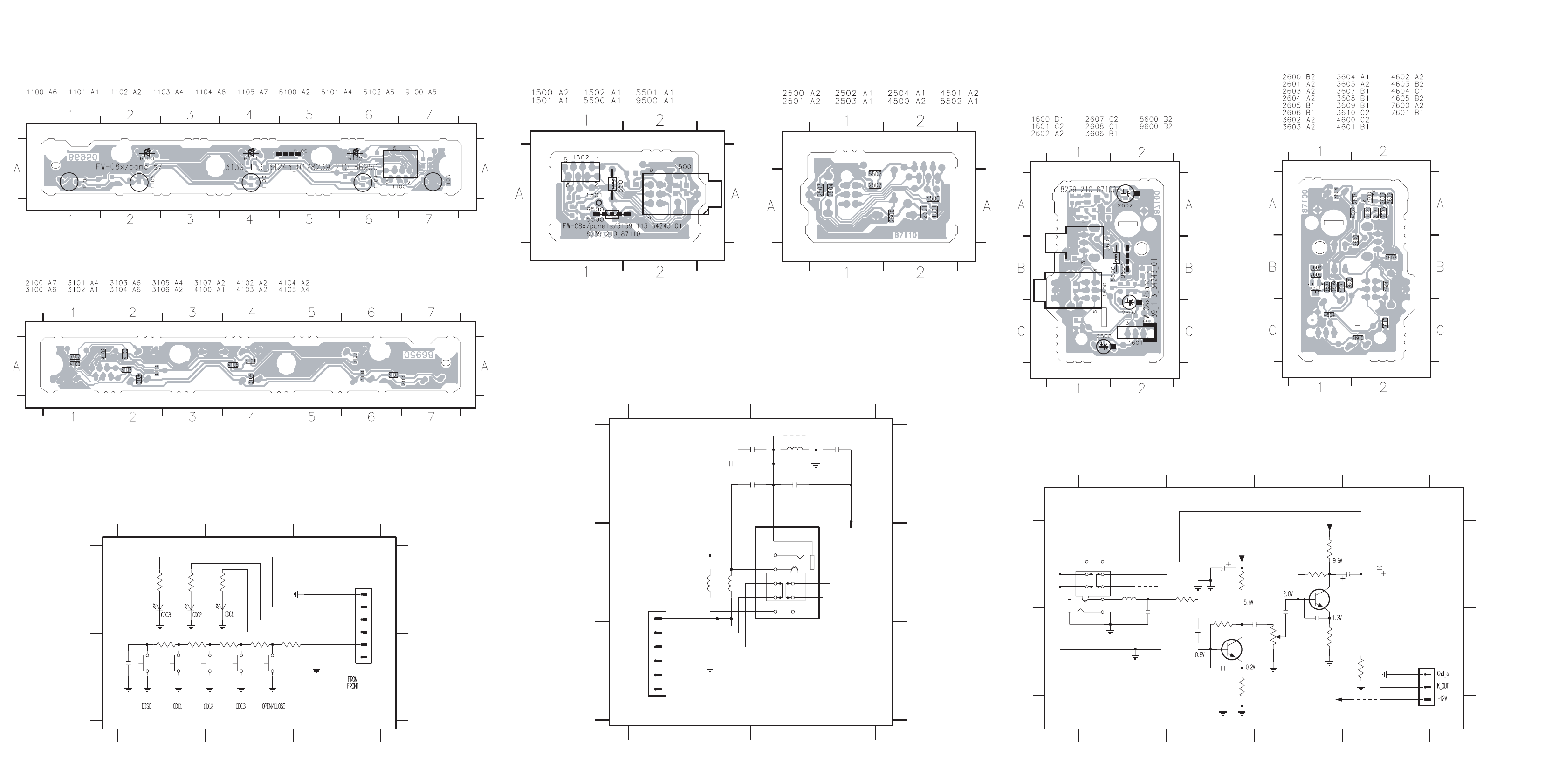
6-4
6-4 6-4
KEY-CDC BOARD - COMPONENT LA YOUT
This assembly drawing shows a summary of all possible versions. For components used in a specific version see schematic diagram and respective parts list.
KEY-CDC BOARD - CHIP LAYOUT
This assembly drawing shows a summary of all possible versions. For components used in a specific version see schematic diagram and respective parts list.
3139 113 3424 pt3 dd wk0035
HEADPHONE BOARD - COMPONENT
LAYOUT
This assembly drawing shows a summary of all possible versions.
For components used in a specific version see schematic diagram and respective parts list.
3139 113 3424 pt3 dd wk0035
HEADPHONE PART - CIRCUIT DIAGRAM
HEADPHONE BOARD - CHIP LAYOUT
This assembly drawing shows a summary of all possible versions.
For components used in a specific version see schematic diagram and respective parts list.
Some location on this board is prepared for both 0603 & 0805 SMDs footprint,
in such locations 0603 SMDs may be substituted.
3139 113 3424 pt3 dd wk0035
KARAOKE BOARD - COMPONENT
LAYOUT
This assembly drawing shows a summary of all possible versions.
For components used in a specific version see schematic diagram
and respective parts list.
KARAOKE BOARD - CHIP LAYOUT
This assembly drawing shows a summary of all possible versions.
For components used in a specific version see schematic diagram
and respective parts list.
Some location on this board is prepared for both 0603 & 0805 SMDs footprint, in such locations 0603 SMDs may be substituted.
KEY-CDC PART - CIRCUIT DIAGRAM
1100 A3
1101 B1
1102 B1
1103 B2
1105 B2
123
Note : Some values may varies, see respective parts list for correct value.
A
2100
100p
3100
6100
3103
1101
120R
3101
6101
1102
120R
3104
4K710K
B
GND-B GND-B
GND-B GND-B
2100 B1
3100 A1
3102
6102
3105
1103
2K7
3101 A1
3102 A2
120R
GND-B
3103 B1
3104 B1
GND
3106
1K8
1104
1105
GND-B
3139 118 53120...86950 for...3424 pt3 dd wk0035
3105 B2
3106 B2
Cdc3Lit
Cdc2Lit
Cdc1Lit
3107
1K2
GND-B
3107 B2
6100 A1 6102 A2
1
2
3
4
5
6
FE-ST-VK-N
6101 A11104 B2
1100
3139 113 3424 pt3 dd wk0035
A
B
1500 B2
1501 A2
1502 B1
2500 A2
2501 A2
2502 A1
12
Note : Some values may varies, see respective
parts list for correct value.
# : Provision
A
B
FE-BT-VK-N
1502
1
2
3
4
5
6
C
DPL_SW
Rhp
R
GNDa
L
Lhp
5501
a
2503 A2
2504 A2
2502
22n
2u2
5502
5500 A2
5501 B1
5502 B1
9500 A2
# 9500
2500
22n
2503
100n
5500 # 2501
2u2
a
2504
100n
1500
22n
1
9
7
8
2u2
4
5
6
1
2
3
TC38
3139 118 53120...87110 for...3424 pt3 dd wk0035
1501
A
B
C
3139 113 3424 pt3 dd wk0035
KARAOKE PART - CIRCUIT DIAGRAM
26 B4
1600 B1
2600 B1
2601 B2
2602 A2
2603 B2
2604 B2
2605 B3
2606 B3
2607 A4
1234
3
2
1
TC38
1600
6
5
4
8
7
9
Mic
5600
2u2
4605
22n
2600
Mic
3602
100R
2601
220n
A
B
Note : Some values may varies, see respective parts list for correct value. 3139 118 53120...87100 for...3424 pt3 dd wk0035
2608 A4
3602 A2
2602
47u
a
3603
1M
2603
1n
+12A
3K9
120R
3603 B2
3604 A2
3604
2604
470n
7600
BC847B
3605
a
Some location on this board is prepared for both 0603 & 0805 SMDs
footprint, in such locations 0603 SMDs may be substituted.
3605 B2
3606 B3
2605
20K
13
a
470n
2
3606
3607 A3
3608 B3
+12A
3607
1M
1n2606
1K2
7601
BC847B
560R
+12A
3609 A3
3610 B4
3609
10u
2607
3608
a
100K
4601
3139 113 3424 pt3 dd wk0035
4600 B4
4601 B4
10u
2608
4600
a
3610
a
4605 A1
5600 A1
DIPMATE
26
1
2
3
7600 B2
7601 A3
A
B
123
12
1234
 Loading...