

Philips 21PV385 58, 21PV385 39, 21PV385 07, 21PV385 01 Service Manual

TV-VCR Combination
Service
21PV385
/01/07/39/58
Service
Service
Service Manual
Contents
Chapter
Adjustment Procedure
Sec. 1:
Schematic Diagrams and CBA's
Exploded Views
Mechanical and Electrical Parts Lists
Survey of versions:
/01 PAL-BG, EURO
/07 PAL I, UK/IRELAND
/39 PAL/SECAM-BG+PAL/SECAM-L/L',FRANCE
/58 PAL-BG/DK+SECAM-BG/DK,EAST-EURO
VN: 1A
Sec. 2:
Standard Maintenance
Mechanism Alignment Procedures
Disassembly / Assembly of Mechanism
Deck Exploded Views
Safety regulations require that the set be restored to its original
condition and that parts which are identical with those specified
be used.
Published by BK 2004 Video Service Department Printed in the Netherlands c
Copyright reserved Subject to modification GB 3103 785 22300

MAIN SECTION
TV-VCR COMBINATION
Sec. 1: Main Section
I Adjustment Procedures
I Schematic Diagrams and CBA’s
I Exploded Views
I Mechanical and Electrical Parts List
TABLE OF CONTENTS
IMPORTANT SAFETY PRECAUTIONS . . . . . . . . . . . . . . . . . . . . . . . . . . . . . . . . . . . . . . . . . . . . . . . . . . . . . . 1-1-1
STANDARD NOTES FOR SERVICING . . . . . . . . . . . . . . . . . . . . . . . . . . . . . . . . . . . . . . . . . . . . . . . . . . . . . . 1-2-1
PREPARATION FOR SERVICING . . . . . . . . . . . . . . . . . . . . . . . . . . . . . . . . . . . . . . . . . . . . . . . . . . . . . . . . . . 1-3-1
OPERATING CONTROLS AND FUNCTIONS . . . . . . . . . . . . . . . . . . . . . . . . . . . . . . . . . . . . . . . . . . . . . . . . . 1-4-1
CABINET DISASSEMBLY INSTRUCTIONS. . . . . . . . . . . . . . . . . . . . . . . . . . . . . . . . . . . . . . . . . . . . . . . . . . . 1-5-1
ELECTRICAL ADJUSTMENT INSTRUCTIONS . . . . . . . . . . . . . . . . . . . . . . . . . . . . . . . . . . . . . . . . . . . . . . . . 1-6-1
BLOCK DIAGRAMS . . . . . . . . . . . . . . . . . . . . . . . . . . . . . . . . . . . . . . . . . . . . . . . . . . . . . . . . . . . . . . . . . . . . . 1-7-1
SCHEMATIC DIAGRAMS / CBA’S AND TEST POINTS . . . . . . . . . . . . . . . . . . . . . . . . . . . . . . . . . . . . . . . . . 1-8-1
WAVEFORMS . . . . . . . . . . . . . . . . . . . . . . . . . . . . . . . . . . . . . . . . . . . . . . . . . . . . . . . . . . . . . . . . . . . . . . . . . . 1-9-1
WIRING DIAGRAM . . . . . . . . . . . . . . . . . . . . . . . . . . . . . . . . . . . . . . . . . . . . . . . . . . . . . . . . . . . . . . . . . . . . 1-10-1
SYSTEM CONTROL TIMING CHARTS . . . . . . . . . . . . . . . . . . . . . . . . . . . . . . . . . . . . . . . . . . . . . . . . . . . . . 1-11-1
IC PIN FUNCTION DESCRIPTIONS . . . . . . . . . . . . . . . . . . . . . . . . . . . . . . . . . . . . . . . . . . . . . . . . . . . . . . . 1-12-1
LEAD IDENTIFICATIONS . . . . . . . . . . . . . . . . . . . . . . . . . . . . . . . . . . . . . . . . . . . . . . . . . . . . . . . . . . . . . . . . 1-13-1
ELECTRICAL PARTS LIST . . . . . . . . . . . . . . . . . . . . . . . . . . . . . . . . . . . . . . . . . . . . . . . . . . . . . . . . . . . . . . . 1-14-1
EXPLODED VIEWS . . . . . . . . . . . . . . . . . . . . . . . . . . . . . . . . . . . . . . . . . . . . . . . . . . . . . . . . . . . . . . . . . . . . 1-15-1
MECHANICAL PARTS LIST . . . . . . . . . . . . . . . . . . . . . . . . . . . . . . . . . . . . . . . . . . . . . . . . . . . . . . . . . . . . . . 1-16-1
IMPORTANT SAFETY PRECAUTIONS
Prior to shipment from the factory, our products are strictly inspected for recognized product safety and electrical
codes of the countries in which they are to be sold. However, in order to maintain such compliance, it is equally
important to implement the following precautions when a set is being serviced.
Safety Precautions for TV Circuit
1. Before returning an instrument to the customer, always make a safety check of the entire instru-
ment, including, but not limited to, the following
items:
a. Be sure that no built-in protective devices are de-
fective and have been defeated during servicing.
(1) Protective shields are provided on this chassis
to protect both the technician and the customer.
Correctly replace all missing protective shields, including any removed for servicing convenience.
(2) When reinstalling the chassis and/or other assembly in the cabinet, be sure to put back in place
all protective devices, including but not limited to,
nonmetallic control knobs, insulating fishpapers,
adjustment and compartment covers/shields, and
isolation resistor/capacitor networks. Do not oper-
ate this instrument or permit it to be operated
without all protective devices correctly installed and functioning. Servicers who defeat
safety features or fail to perform safety checks
may be liable for any resulting damage.
b. Be sure that there are no cabinet openings through
which an adult or child might be able to insert their
fingers and contact a hazardous voltage. Such
openings include, but are not limited to, (1) spacing between the picture tube and the cabinet
mask, (2) excessively wide cabinet ventilation
slots, and (3) an improperly fitted and/or incorrectly
secured cabinet back cover.
c. Antenna Cold Check - With the instrument AC
plug removed from any AC source, connect an
electrical jumper across the two AC plug prongs.
Place the instrument AC switch in the on position.
Connect one lead of an ohmmeter to the AC plug
prongs tied together and touch the other ohmmeter lead in turn to each tuner antenna input exposed terminal screw and, if applicable, to the
coaxial connector. If the measured resistance is
less than 1.0 megohm or greater than 5.2 megohm, an abnormality exists that must be corrected
before the instrument is returned to the customer.
Repeat this test with the instrument AC switch in
the off position.
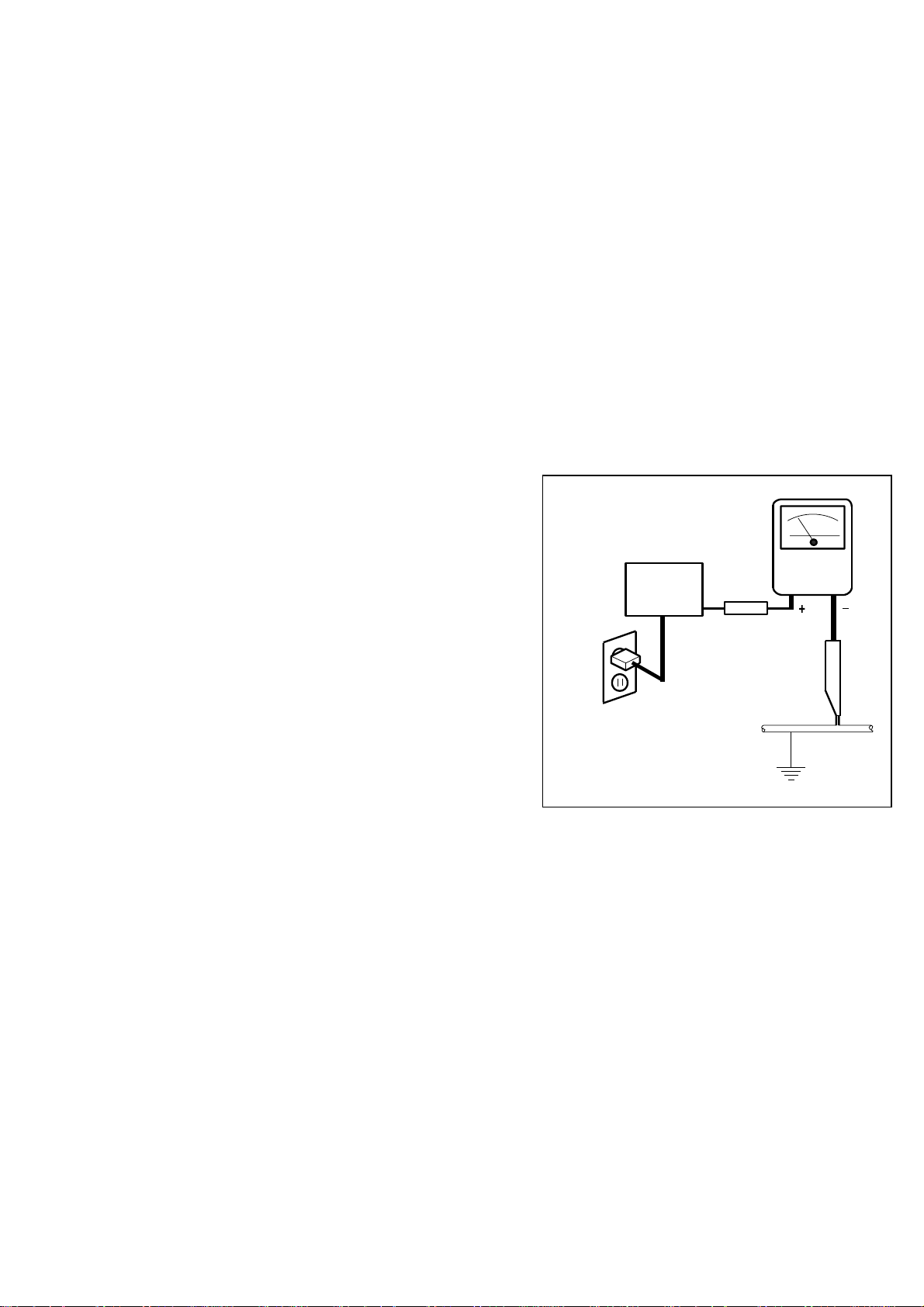
d. Leakage Current Hot Check - With the instru-
ment completely reassembled, plug the AC line
cord directly into a 120V AC outlet. (Do not use an
isolation transformer during this test.) Use a leak-
age current tester or a metering system that complies with American National Standards Institute
(ANSI) C101.1 Leakage Current for Appliances
and Underwriters Laboratories (UL) 1410, (50.7).
With the instrument AC switch first in the on position and then in the off position, measure from a
known earth ground (metal water pipe, conduit,
etc.) to all exposed metal parts of the instrument
(antennas, handle brackets, metal cabinet, screw
heads, metallic overlays, control shafts, etc.), especially any exposed metal parts that offer an electrical return path to the chassis. Any current
measured must not exceed 0.5 milli-ampere. Reverse the instrument power cord plug in the outlet
and repeat the test.
READING SHOULD
NOT BE ABOVE 0.5 mA
LEAKAGE
DEVICE
BEING
TESTED
TEST ALL EXPOSED
METAL SURFACES
ALSO TEST WITH
PLUG REVERSED
USING AC
ADAPTER PLUG
AS REQUIRED
CURRENT
TESTER
EARTH
GROUND
ANY MEASUREMENTS NOT WITHIN THE LIMITS
SPECIFIED HEREIN INDICATE A POTENTIAL
SHOCK HAZARD THAT MUST BE ELIMINATED
BEFORE RETURNING THE INSTRUMENT TO
THE CUSTOMER OR BEFORE CONNECTING
THE ANTENNA OR ACCESSORIES.
e. X-Radiation and High Voltage Limits - Because
the picture tube is the primary potential source of
X-radiation in solid-state TV receivers, it is specially constructed to prohibit X-radiation emissions.
For continued X-radiation protection, the replacement picture tube must be the same type as the
original. Also, because the picture tube shields
and mounting hardware perform an X-radiation
protection function, they must be correctly in place.
High voltage must be measured each time servic-
1-1-1 T6550SFTY

ing is performed that involves B+, horizontal deflection or high voltage. Correct operation of the
X-radiation protection circuits also must be reconfirmed each time they are serviced. (X-radiation
protection circuits also may be called "horizontal
disable" or "hold down.") Read and apply the high
voltage limits and, if the chassis is so equipped,
the X-radiation protection circuit specifications given on instrument labels and in the Product Safety
& X-Radiation Warning note on the service data
chassis schematic. High voltage is maintained
within specified limits by close tolerance safety-related components/adjustments in the high-voltage
circuit. If high voltage exceeds specified limits,
check each component specified on the chassis
schematic and take corrective action.
2. Read and comply with all caution and safety-related notes on or inside the receiver cabinet, on the
receiver chassis, or on the picture tube.
3. Design Alteration Warning - Do not alter or add
to the mechanical or electrical design of this TV receiver. Design alterations and additions, including,
but not limited to circuit modifications and the addition of items such as auxiliary audio and/or video
output connections, might alter the safety characteristics of this receiver and create a hazard to the
user. Any design alterations or additions will void
the manufacturer's warranty and may make you,
the servicer, responsible for personal injury or
property damage resulting therefrom.
4. Picture Tube Implosion Protection Warning -
The picture tube in this receiver employs integral
implosion protection. For continued implosion protection, replace the picture tube only with one of
the same type number. Do not remove, install, or
otherwise handle the picture tube in any manner
without first putting on shatterproof goggles
equipped with side shields. People not so
equipped must be kept safely away while picture
tubes are handled. Keep the picture tube away
from your body. Do not handle the picture tube by
its neck. Some "in-line" picture tubes are equipped
with a permanently attached deflection yoke; because of potential hazard, do not try to remove
such "permanently attached" yokes from the picture tube.
5. Hot Chassis Warning -
a. Some TV receiver chassis are electrically connect-
ed directly to one conductor of the AC power cord
and maybe safety-serviced without an isolation
transformer only if the AC power plug is inserted
so that the chassis is connected to the ground side
of the AC power source. To confirm that the AC
power plug is inserted correctly, with an AC voltmeter, measure between the chassis and a known
earth ground. If a voltage reading in excess of 1.0V
is obtained, remove and reinsert the AC power
plug in the opposite polarity and again measure
the voltage potential between the chassis and a
known earth ground.
b. Some TV receiver chassis normally have 85V
AC(RMS) between chassis and earth ground regardless of the AC plug polarity. This chassis can
be safety-serviced only with an isolation transformer inserted in the power line between the receiver
and the AC power source, for both personnel and
test equipment protection.
c. Some TV receiver chassis have a secondary
ground system in addition to the main chassis
ground. This secondary ground system is not isolated from the AC power line. The two ground systems are electrically separated by insulation
material that must not be defeated or altered.
6. Observe original lead dress. Take extra care to assure correct lead dress in the following areas: a.
near sharp edges, b. near thermally hot parts-be
sure that leads and components do not touch thermally hot parts, c. the AC supply, d. high voltage,
and e. antenna wiring. Always inspect in all areas
for pinched, out of place, or frayed wiring. Check
AC power cord for damage.
7. Components, parts, and/or wiring that appear to
have overheated or are otherwise damaged
should be replaced with components, parts, or wiring that meet original specifications. Additionally,
determine the cause of overheating and/or damage and, if necessary, take corrective action to remove any potential safety hazard.
8. Product Safety Notice - Some electrical and mechanical parts have special safety-related characteristics which are often not evident from visual
inspection, nor can the protection they give necessarily be obtained by replacing them with components rated for higher voltage, wattage, etc.. Parts
that have special safety characteristics are identified by a ( ! ) on schematics and in parts lists. Use
of a substitute replacement that does not have the
same safety characteristics as the recommended
replacement part might create shock, fire, and/or
other hazards. The Product's Safety is under review continuously and new instructions are issued
whenever appropriate. Prior to shipment from the
factory, our products are strictly inspected to confirm with the recognized product safety and electrical codes of the countries in which they are to be
sold. However, in order to maintain such compliance, it is equally important to implement the following precautions when a set is being serviced.
1-1-2 T6550SFTY

Precautions during Servicing
A. Parts identified by the ( ! ) symbol are critical for
safety.
Replace only with part number specified.
B. In addition to safety, other parts and assemblies
are specified for conformance with regulations applying to spurious radiation. These must also be replaced only with specified replacements.
Examples: RF converters, RF cables, noise blocking capacitors, and noise blocking filters, etc.
C. Use specified internal wiring. Note especially:
1) Wires covered with PVC tubing
2) Double insulated wires
3) High voltage leads
D. Use specified insulating materials for hazardous
live parts. Note especially:
1) Insulation Tape
2) PVC tubing
3) Spacers
4) Insulators for transistors.
E. When replacing AC primary side components
(transformers, power cord, etc.), wrap ends of
wires securely about the terminals before soldering.
F. Observe that the wires do not contact heat produc-
ing parts (heatsinks, oxide metal film resistors, fusible resistors, etc.)
G. Check that replaced wires do not contact sharp
edged or pointed parts.
H. When a power cord has been replaced, check that
5~6 kg of force in any direction will not loosen it.
I. Also check areas surrounding repaired locations.
J. Use care that foreign objects (screws, solder drop-
lets, etc.) do not remain inside the set.
K. Crimp type wire connector
When replacing the power transformer in sets
where the connections between the power cord
and power transformer primary lead wires are performed using crimp type connectors, in order to
prevent shock hazards, perform carefully and precisely the following steps.
Replacement procedure
1) Remove the old connector by cutting the wires at a
point close to the connector.
Important: Do not re-use a connector (discard it).
2) Strip about 15 mm of the insulation from the ends
of the wires. If the wires are stranded, twist the
strands to avoid frayed conductors.
3) Align the lengths of the wires to be connected. Insert the wires fully into the connector.
4) Use the crimping tool to crimp the metal sleeve at
the center position. Be sure to crimp fully to the
complete closure of the tool.
L. When connecting or disconnecting the VCR con-
nectors, first, disconnect the AC plug from AC supply socket.
1-1-3 T6550SFTY
Safety Check after Servicing
Examine the area surrounding the repaired location for
damage or deterioration. Observe that screws, parts
and wires have been returned to original positions.
Afterwards, perform the following tests and confirm the
specified values in order to verify compliance with
safety standards.
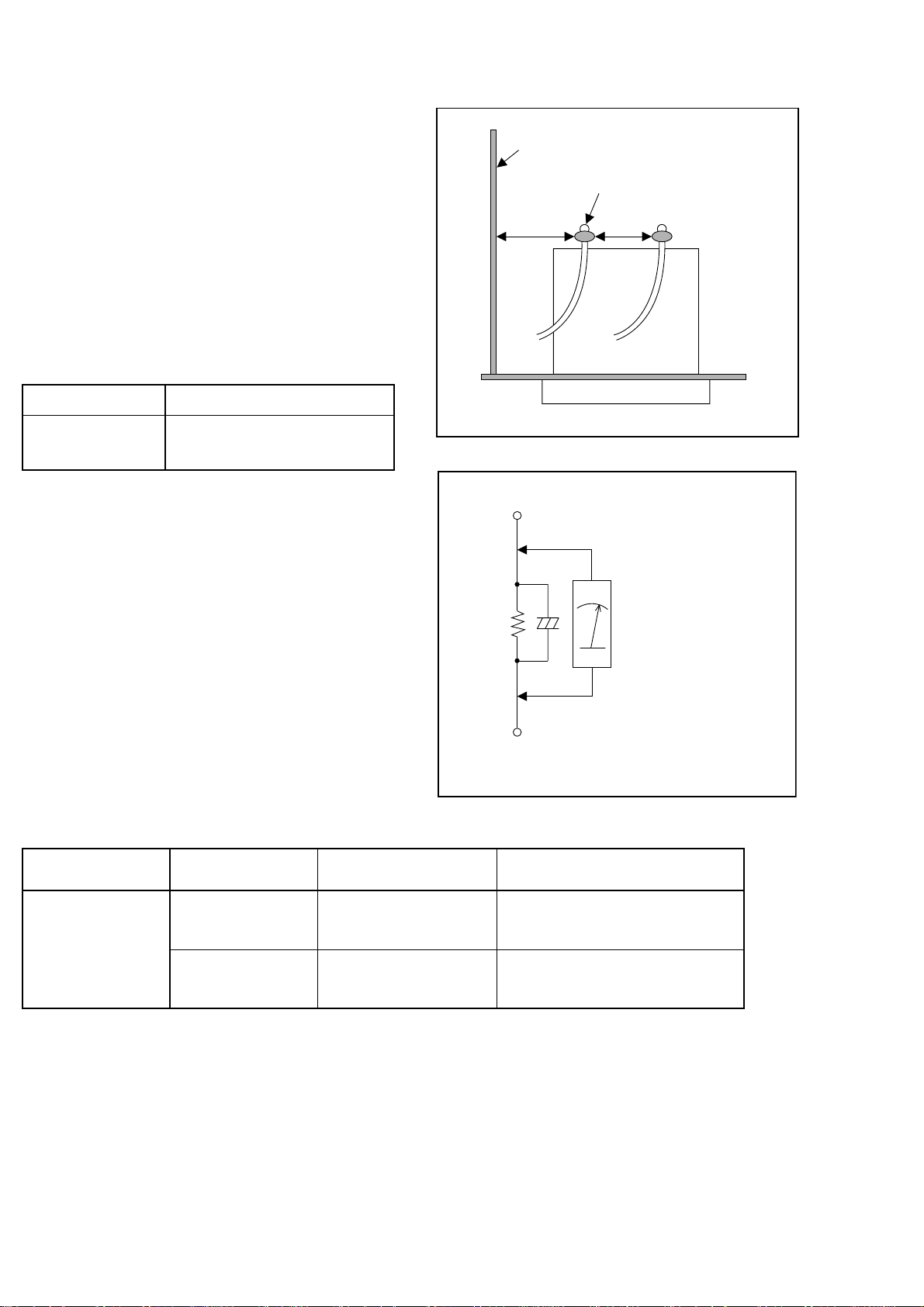
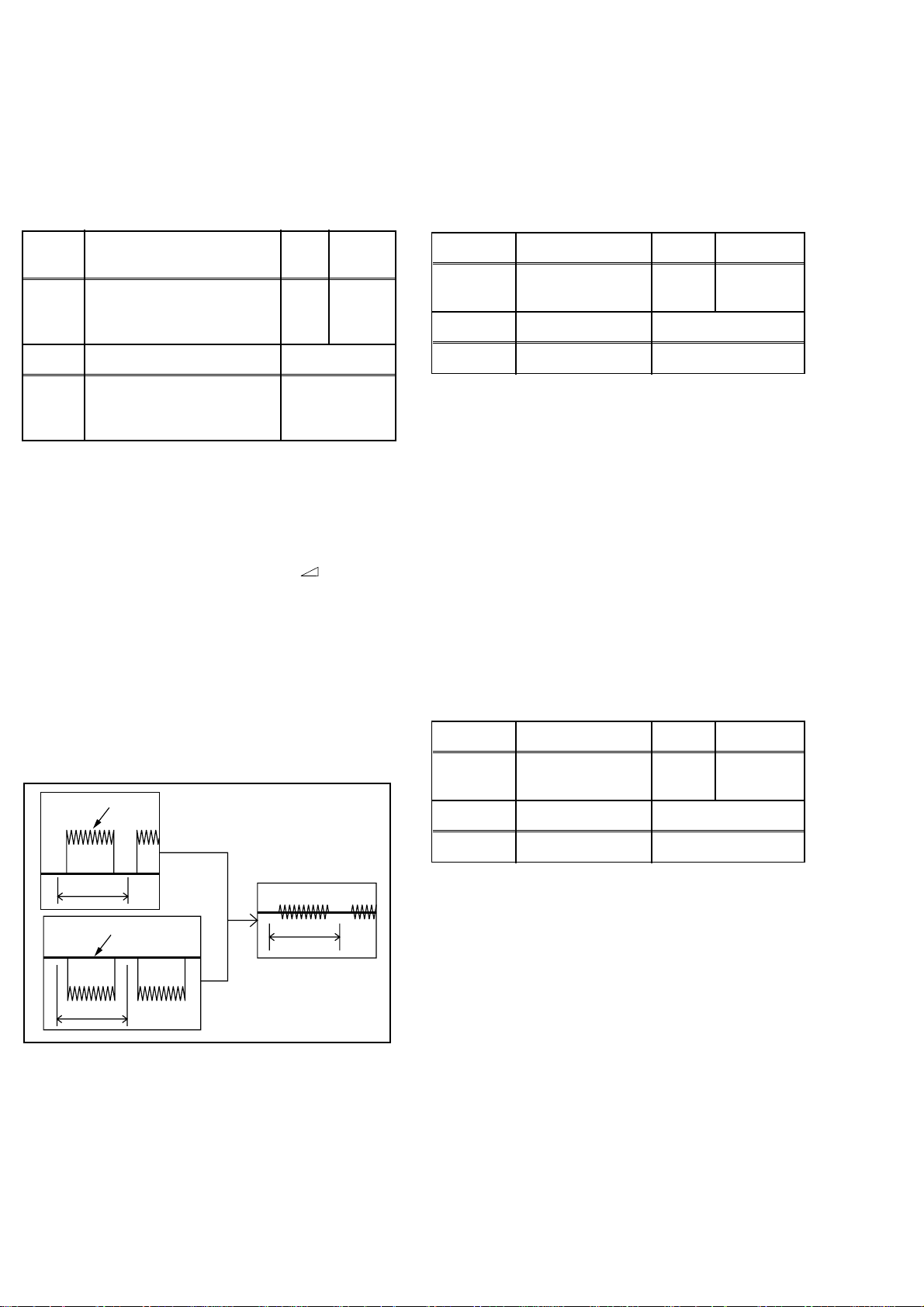
1. Clearance Distance
When replacing primary circuit components, confirm
specified clearance distance (d) and (d') between soldered terminals, and between terminals and surrounding metallic parts. (See Fig. 1)
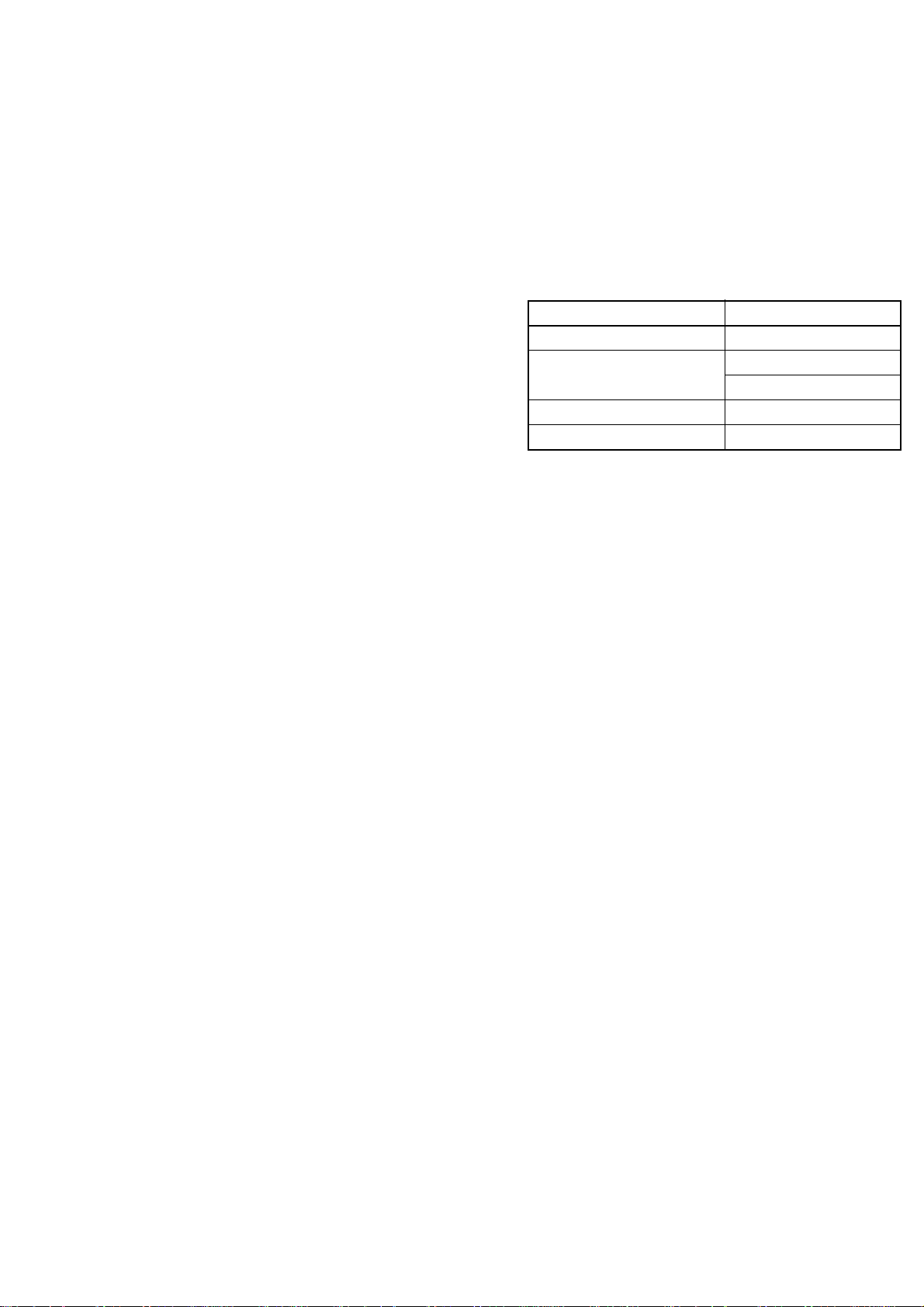
Table 1 : Ratings for selected area
AC Line Voltage Clearance Distance (d) (d’)
220 to 240 V
Note: This table is unofficial and for reference only.
Be sure to confirm the precise values.
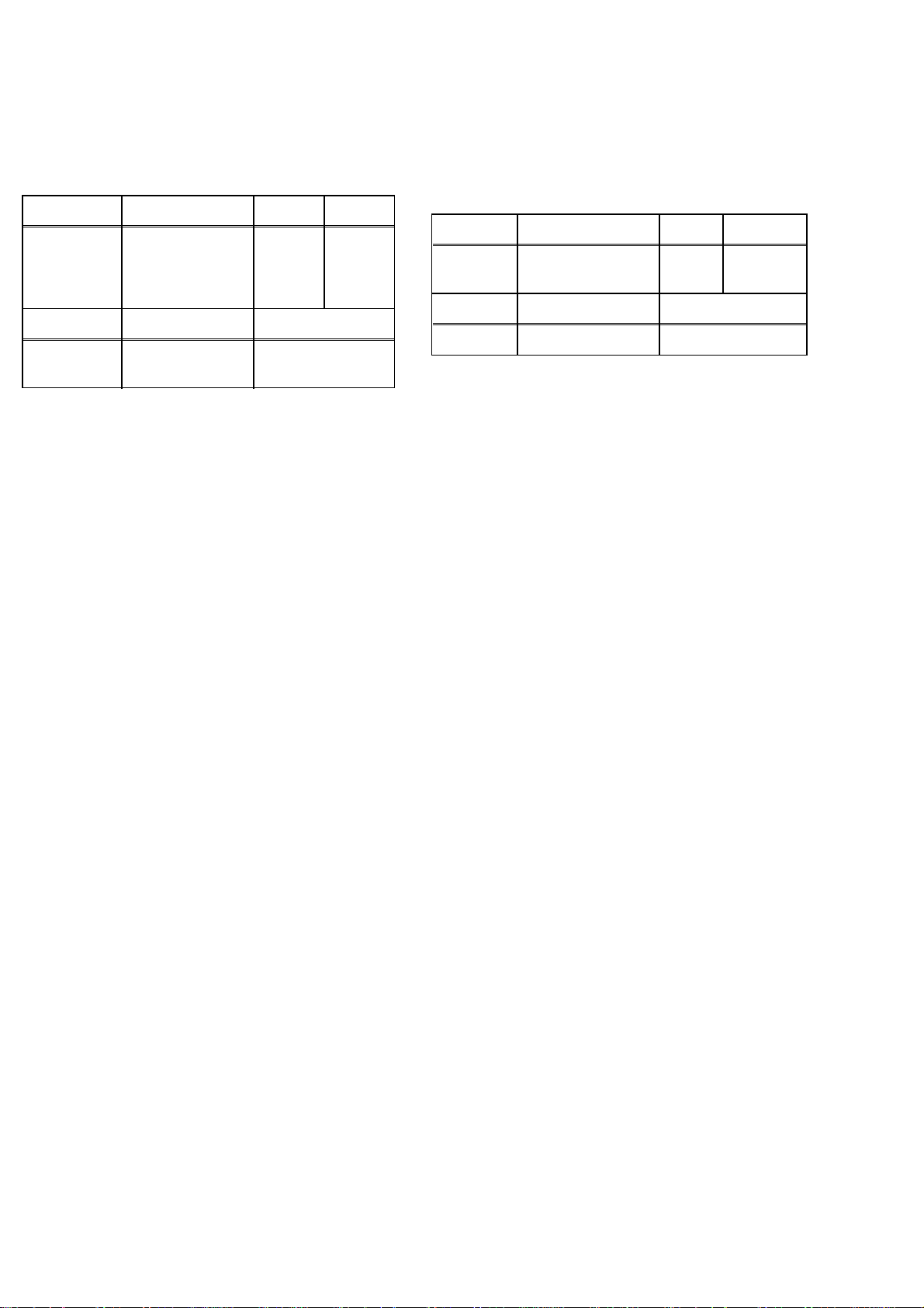
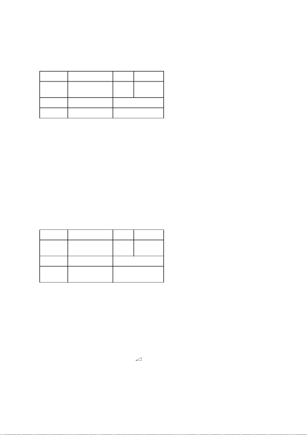
2. Leakage Current Test
Confirm the specified (or lower) leakage current between B (earth ground, power cord plug prongs) and
externally exposed accessible parts (RF terminals, antenna terminals, video and audio input and output terminals, microphone jacks, earphone jacks, etc.).
≥ 3mm(d)
≥ 6 mm(d’)
Chassis or Secondary Conductor
Primary Circuit Terminals
dd’
Exposed Accessible Part
Z
AC Voltmeter
(High Impedance)
Fig. 1
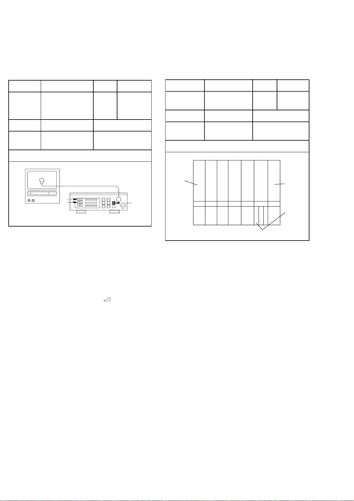
Measuring Method : (Power ON)
Insert load Z between B (earth ground, power cord
plug prongs) and exposed accessible parts. Use an
AC voltmeter to measure across both terminals of load
Z. See Fig. 2 and following table.
Table 2: Leakage current ratings for selected areas
AC Line Voltage Load Z Leakage Current (i)
2kΩ RES.
Connected in
220 to 240 V
Note: This table is unofficial and for reference only. Be sure to confirm the precise values.
parallel
50kΩ RES.
Connected in
parallel
i≤0.7mA AC Peak
i≤2mA DC
i≤0.7mA AC Peak
i≤2mA DC
One side of
B
Power Cord Plug Prongs
One side of power cord plug
prongs (B) to:
RF or
Antenna terminals
A/V Input, Output
Fig. 2
1-1-4 T6550SFTY
STANDARD NOTES FOR SERVICING
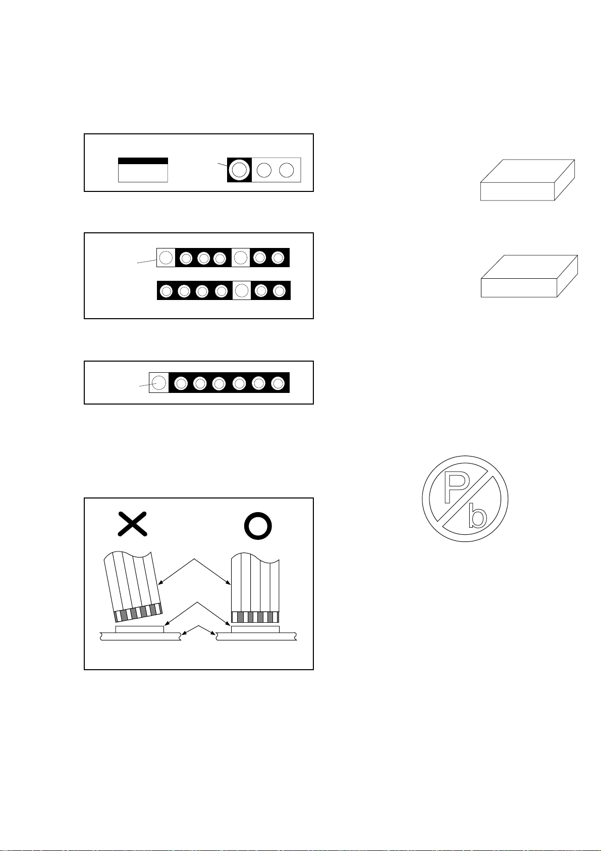
Circuit Board Indications
1. The output pin of the 3 pin Regulator ICs is indicated as shown:
Top View
Out
2. For other ICs, pin 1 and every 5th pin is indicated
as shown:
Pin 1
3. The 1st pin of every pin connector are indicated as
shown:
Input
In
Bottom View
5
10
How to Read the Values of the Rectangular Type Chip Components
Example:
(a) Resistor
473
= 473 = 47 [kΩ]
(b) Capacitor
= Not Shown
Caution:
Once chip parts (Resistors, Capacitors, Transistors,
etc.) are removed, they must not be reused. Always
use a new part.
(Top View)
(Top View)
Pin 1
Instructions for Connectors
1. When you connect or disconnect FFC cable (connector), be sure to disconnect the AC cord.
2. FFC cable (connector) should be inserted parallel
into the connector, not at an angle.
FFC Cable
Connector
CBA
* Be careful to avoid a short circuit.
[ CBA= Circuit Board Assembly ]
Pb (Lead) Free Solder
Pb free mark will be found on PCBs used Pb free
solder. (Refer to figure.) For PCBs with Pb free
mark, be sure to use Pb free solder. For PCBs
without Pb free mark, use standard solder.
Pb free mark
Replacement Procedures for
Leadless (Chip) Components
The Following Procedures are Recommended for the Replacement of the Leadless Components Used in this Unit.
1. Preparation for replacement
1.1. Pb free solder
a. Soldering Iron
Use a soldering iron for Pb free solder.
b. Solder
Be sure to use Pb free solder.
c. Soldering time
Do not apply heat for more than 4 seconds.
d. Preheating
Leadless capacitor must be preheated before
installation. (130°C~150°C, for about two minutes.)
1-2-1 SFTY_Z13P
1.2. Standard solder
a. Soldering Iron
Use a pencil-type soldering iron (less than 30
watts).
b. Solder
Eutectic solder (Tin 63%, Lead 37%) is recommended.
c. Soldering time
Do not apply heat for more than 4 seconds.
d. Preheating
Leadless capacitor must be preheated before
installation. (130°C~150°C, for about two minutes.)
Notes:
a. Leadless components must not be reused after
removal.
b. Excessive mechanical stress and rubbing for the
component electrode must be avoided.
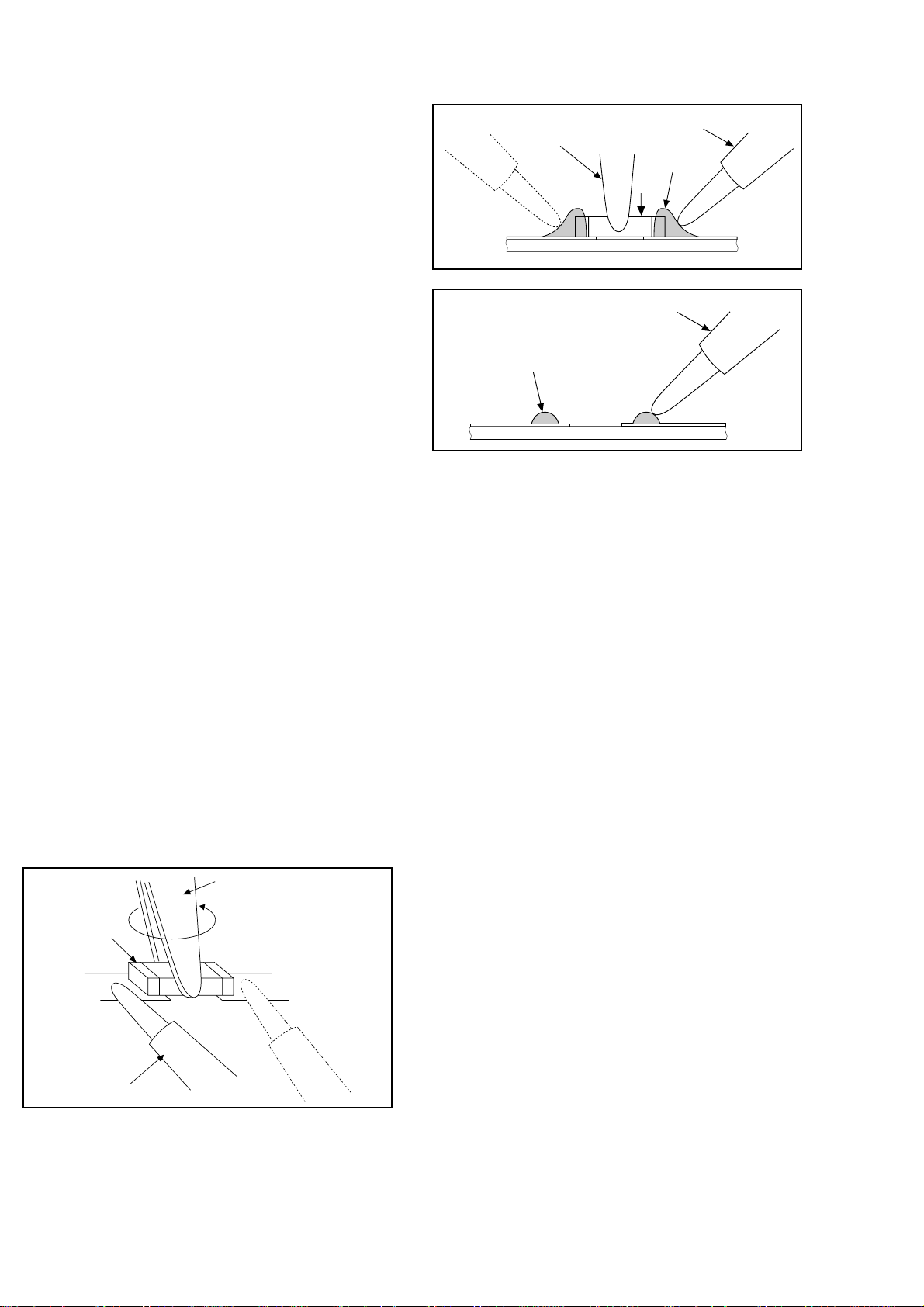
2. Removing the leadless component
Grasp the leadless component body with tweezers
and alternately apply heat to both electrodes. When
the solder on both electrodes has melted, remove
leadless component with a twisting motion.
Notes:
a. Do not attempt to lift the component off the board
until the component is completely disconnected
from the board by the twisting action.
b. Take care not to break the copper foil on the printed
board
3. Installing the leadless component
a. Presolder the contact points of the circuit board.
b. Press the part downward with tweezers and solder
both electrodes as shown below.
Note:
Do not glue the replacement leadless component to
the circuit board.
Tweezers
Chip
Soldering Iron
Tweezers
Soldering Iron
Solder
Soldering Iron
Presolder
How to Remove / Install Flat Pack IC
Caution:
1. The Flat Pack-IC shape may differ by models. Use
an appropriate hot-air flat pack-IC desoldering machine, whose shape matches that of the Flat PackIC.
2. Do not apply the hot air to the chip parts around the
Flat Pack-IC for over 6 seconds as damage may
occur to the chip parts. Put Masking Tape around
the Flat Pack-IC to protect other parts from damage. (Fig. S-1-2)
3. The Flat Pack-IC on the CBA is affixed with glue, so
be careful not to break or damage the foil of each
pin or solder lands under the IC when removing it.
1. Removal
With Hot - Air Flat Pack - IC Desoldering Machine:
a. Prepare the Hot - Air Flat Pack - IC Desoldering
Machine, then apply hot air to Flat Pack - IC (about
5~6 seconds). (Fig. S-1-1)
b. Remove the Flat Pack- IC with tweezers while
applying the hot air.
With Soldering Iron:
a. Using desoldering braid, remove the solder from all
pins of the Flat Pack - IC. When you use solder flux
which is applied to all pins of the Flat Pack - IC, you
can remove it easily. (Fig. S-1-3)
b. Lift each lead of the Flat Pack - IC upward one by
one, using a sharp pin or wire to which solder will
not adhere (iron wire). When heating the pins, use
a fine tip soldering iron or a hot air Desoldering
Machine. (Fig. S-1-4)
With Iron Wire:
a. Using desoldering braid, remove the solder from all
pins of the Flat Pack - IC. When you use solder flux
which is applied to all pins of the Flat Pack - IC, you
can remove it easily. (Fig. S-1-3)
1-2-2 SFTY_Z13P
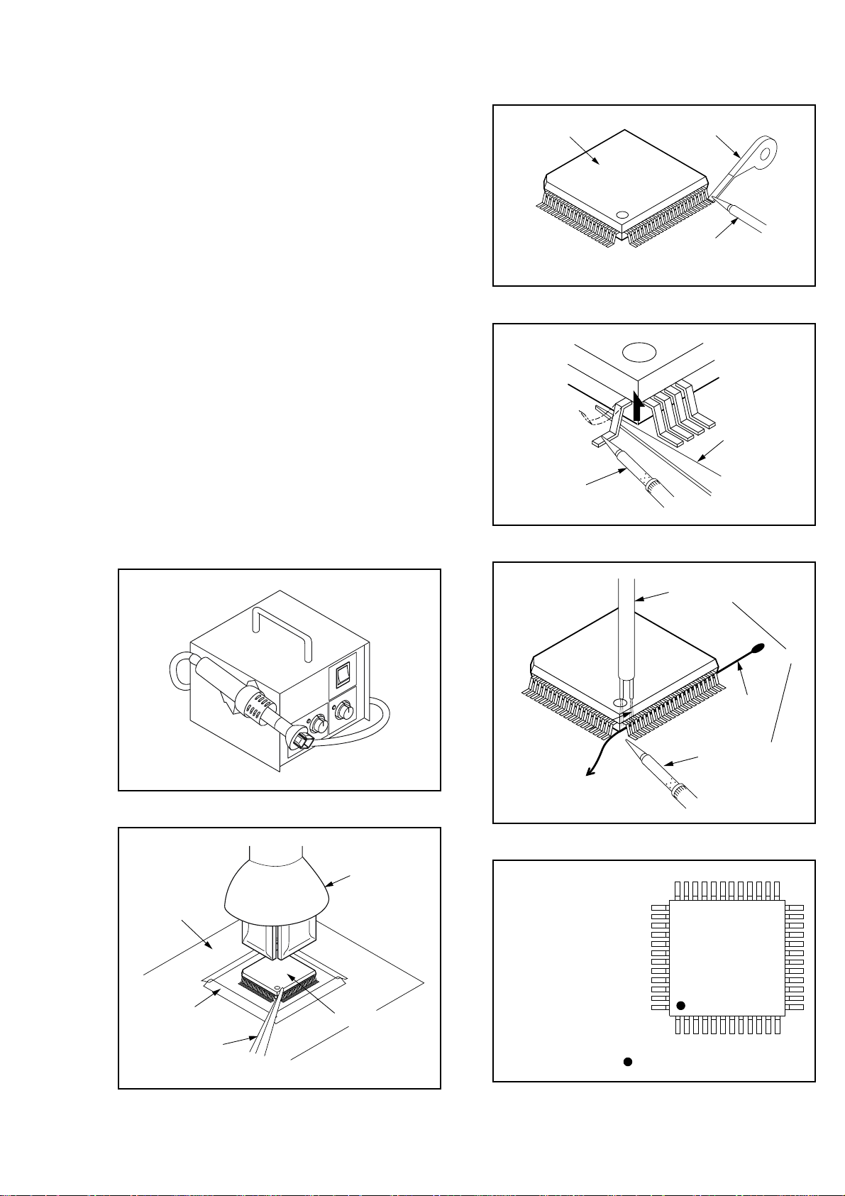
b. Affix the wire to a workbench or solid mounting
point, as shown in Fig. S-1-5.
c. Pull up on the wire as the solder melts so as to lift
the IC leads from the CBA contact pads, while
heating the pins using a fine tip soldering iron or
hot air blower.
Note:
When using a soldering iron, care must be taken
to ensure that the Flat Pack - IC is not being held
by glue, or when it is removed from the CBA, it
may be damaged if force is used.
2. Installation
a. Using desoldering braid, remove the solder from
the foil of each pin of the Flat Pack - IC on the CBA,
so you can install a replacement Flat Pack - IC
more easily.
b. The "I" mark on the Flat Pack - IC indicates pin 1
(See Fig. S-1-6). Make sure this mark matches the
1 on the CBA when positioning for installation.
Then pre - solder the four corners of the Flat PackIC (See Fig. S-1-7).
c. Solder all pins of the Flat Pack - IC. Make sure that
none of the pins have solder bridges.
Flat Pack-IC
Fine Tip
Soldering Iron
Desoldering Braid
Soldering Iron
Fig. S-1-3
Sharp
Pin
Fig. S-1-4
CBA
Fig. S-1-1
Hot-air
Flat Pack-IC
Desoldering
Machine
Hot Air Blower
or
Iron Wire
Soldering Iron
To Solid
Mounting Point
Fig. S-1-5
Example :
Masking
Tape
Tweezers
Flat Pack-IC
Fig. S-1-2
Pin 1 of the Flat Pack-IC
is indicated by a " " mark.
1-2-3 SFTY_Z13P
Fig. S-1-6
Presolder
<Correct>
Grounding Band
1MΩ
CBA
Flat Pack-IC
CBA
Fig. S-1-7
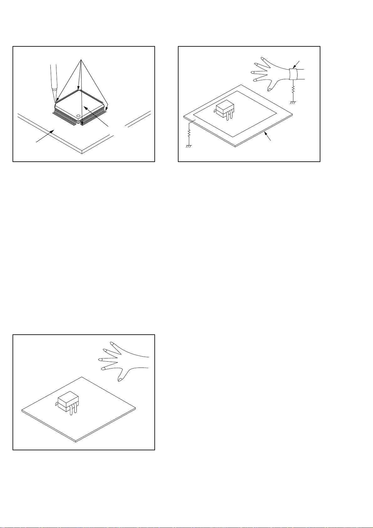
Instructions for Handling
Semiconductors
Electrostatic breakdown of the semiconductors may
occur due to a potential difference caused by electrostatic charge during unpacking or repair work.
Ground for Human Body
Be sure to wear a grounding band (1MΩ) that is properly grounded to remove any static electricity that may
be charged on the body.
Ground for Work Bench
Be sure to place a conductive sheet or copper plate
with proper grounding (1MΩ) on the work bench or
other surface, where the semiconductors are to be
placed. Because the static electricity charge on the
clothing will not escape through the body grounding
band, be careful to avoid contacting semiconductors to
clothing.
1MΩ
Conductive Sheet or
Copper Plate
<Incorrect>
CBA
1-2-4 SFTY_Z13P

PREPARATION FOR SERVICING
How to Enter the Service Mode
Caution: 1
1. Optical sensors system are used for Tape Start and
End Sensor on this equipment. Read this page
carefully and prepare as described on this page
before starting to service; otherwise, the unit may
operate unexpectedly.
Preparing: 1
1. Cover Q202 (START SENSOR) and Q201 (END
SENSOR) with Insulation Tape or enter the service
mode to activate Sensor Inhibition automatically.
Note: Avoid playing, rewinding or fast forwarding the
tape to its beginning or end, because both Tape End
Sensors are not active.
How to Enter the Service Mode
1. Turn the power on. (Use main power on the TV
unit.)
2. Press [STANDBY/ON], [2], [7], [1], and [MUTE] buttons on the remote control unit in that order within 5
seconds. When entering the service mode, “4” will
display at corners of the screen.
3. During the service mode, electrical adjustment
mode can be selected by remote control key.
Details are as follows.
Key Adjustment Mode
6 No need to use.
7 No need to use.
8
9
Caution: 2
1. The deck mechanism assembly is mounted on the
Main CBA directly, and SW211 (REC-SAFETY
SW) is mounted on the Main CBA. When deck
mechanism assembly is removed from the Main
CBA due to servicing, this switch can not be operated automatically.
H. Shift adjustment mode: See adjustment instructions page 1-6-5.
V.size/V. shift adjustment: See adjustment instructions page 1-6-4.
Preparing: 2
1. To eject the tape, press the STOP/EJECT button
on the unit (or Remote Control).
2. When you want to record during the Service mode,
press the Rec button while depressing SW211
(REC-SAFETY SW) on the Main CBA.
Q201
(END SENSOR)
Q202
(START SENSOR)
Key Adjustment Mode
Picture adjustment mode: Press the
MENU button to change from BRT
(Bright), *CNT (Contrast), *COL
MENU
-
0
1
2
3
4
5
(Color), *TNT(Tint) and SHP(SHARP).
Press P+/P- key to adjust Initial Value.
*Marked items are not necessary to
adjust normally.
SECAM Black Level adjustment mode:
See adjustment instructions page
1-6-4.
Cut-Off adjustment mode: See adjustment instructions page 1-6-5.
White Balance adjustment mode: See
adjustment instructions page 1-6-6.
C-Trap adjustment mode: See adjustment instructions page 1-6-3.
DSPC adjustment mode: See adjustment instructions page 1-6-3.
H adjustment mode: See adjustment
instructions page 1-6-2.
Head switching point adjustment mode
(Auto adjustment): See adjustment
instructions page 1-6-8.
Auto record mode: Perform recording
(15 Sec.)-->Stop-->Rewind (Zero
return) automatically.
Head switching point adjustment mode
(Manual adjustment): See adjustment
instructions page 1-6-8.
SW211
(REC-SAFETY SW)
MAIN CBA
1-3-1 T6550PFS
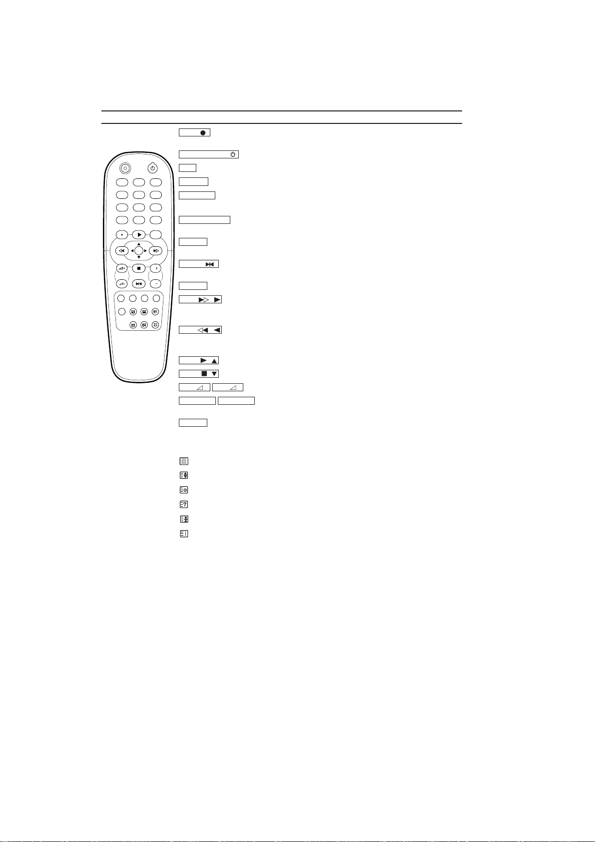
OPERATING CONTROLS AND FUNCTIONS
The remote control
To record the TV channel selected at this moment or press repeatedly to start a
To switch off or on, interrupt menu function.
Press to select channels at TVCR.
To select the switch-off time in 30 minutes intervals.
Doesn’t work on these models. (21PV385/01,07)
To access or remove the TVCR’s on-screen status display. To exit on-
To delete last entry. To clear a programmed recording (TIMER). To reset the
To stop the tape and play back a picture step by step. (except for during fast
To call up main menu of TVCR.
When tape playback is stopped, press to fast forward the tape at high
-
When tape playback is stopped, press to rewind the tape at high speed.
-
To play back a tape, select an item in the menu of TVCR.
-
To stop the tape, select an item in the menu of TVCR.
-
+
VOL
PROG P–PROG P
–
To adjust the volume.
To select the programme number. During playback, press to
+
To eliminate the TV’s sound. Press again to restore the volume.
: To switch Teletext on or off, or transparent mode.
: Enlarge font
: Select Teletext sub-page
: Recall hidden information
:
Stop page changes
: Go back to start page.
REC STANDBY/ON
1 2 3
4 5 6
7 8 9
SLEEP SYSTEM
0
PLAYSTATUS/EXIT CLEAR
REW FWD
MENU
STOP
PROGVOL
STILL
MUTE
REC
One-Touch Recording.
STANDBY/ON
0..9
SLEEP
SYSTEM
To change Video (colour) system. (21PV385/39,58)
STATUS/EXIT
screen menus.
CLEAR
elapsed time counter in the playback, recording or stop mode.
STILL
P
P
forwarding and fast rewinding)
P
MENU
FWD
speed. During playback, press to fast forward the tape while the picture stays on the
screen. To store or confirm entry in the menu. Press to adjust the controls of TVCR menu.
REW
During playback, press to rewind the tape while the picture stays on the screen.To return
the cursor in the menu. Press to adjust the controls of TVCR menu.
PLAY
STOP
VOL
adjust the tracking.
MUTE
Red button/ Green button/ Yellow button/ Blue button/ Doesn’t work on these models.
[21PV385]
1-4-1 T6550IB
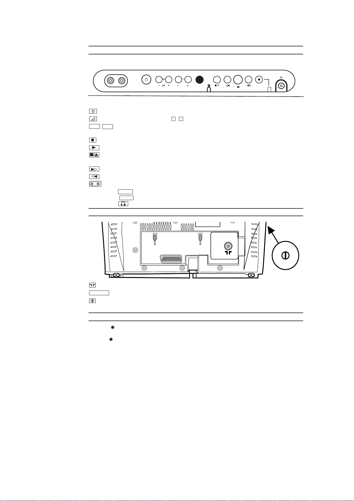
Front of your TVCR
VIDEO AUDIO
STANDBY/ON
P
Standby/on: To switch TVCR on or off, interrupt menu function.
Volume: In connection with the button , to adjust the volume.
P+
Programme number: To select the programme number. During playback, press to adjust the
P-
–+
tracking. To remove vertical jitter in a Still picture.
Record: To record the programme currently selected.
Playback: To play a recorded cassette.
Pause/Stop, eject cassette: To stop the tape; If this key is depressed while in STOP, the cassette is then
ejected from the machine.
When tape playback is stopped, press to fast forward the tape at hight speed.
When tape playback is stoped, press to rewind the tape at hight speed.
Sockets on the front:
White socket / input socket: To connect a camcorder or video game machine (audio).
Yellow socket / input socket: To connect a camcorder or video game machine (video).
AUDIO
VIDEO
Small socket / socket for headphones: To connect headphones.
Back of your TVCR
EXT1/AV1
Aerial input socket: To connect the aerial cable
EXT1/AV
Scart socket :To connect a satellite receiver, decoder, video recorder, etc
Power switch: To switch the TV-Video Combi off.
Caution: If you switch off using the power switch, TIMER-recordings are impossible!
The control lights at the front of machine
STANDBY Standby light: lights up when the TV-Video Combi has been switched on by means of the main
switch.
RECORD Recording light: lights up during recording.
Fast blink: recording pause; timer recording not stand-by.
Slow blink: timer recording is stored in a timer block.
1-4-2 T6550IB
CABINET DISASSEMBLY INSTRUCTIONS
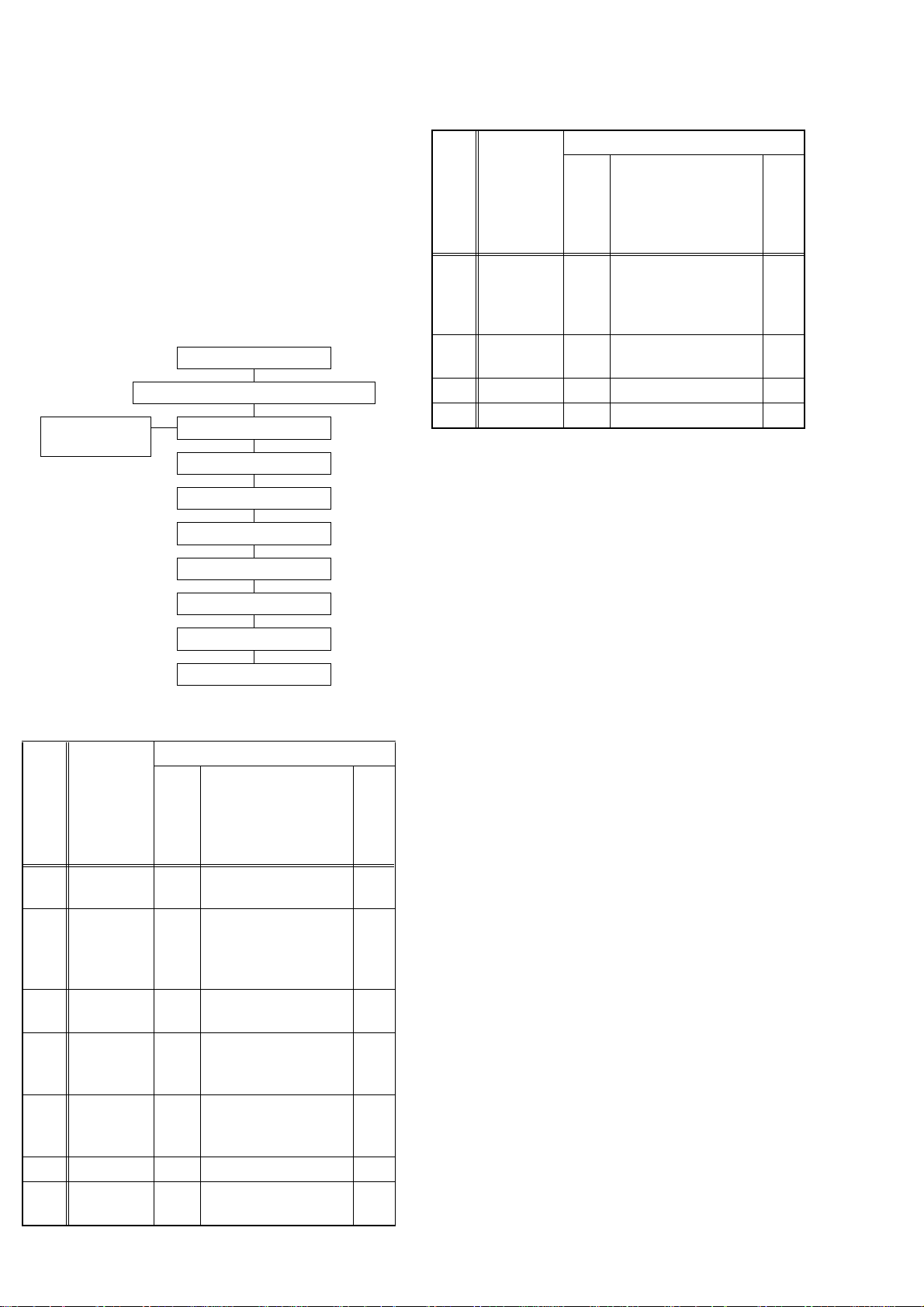
1. Disassembly Flowchart
This flowchart indicates the disassembly steps for the
cabinet parts, and the CBA in order to gain access to
item(s) to be serviced. When reassembling, follow the
steps in reverse order. Bend, route and dress the
cables as they were.
Caution !!
When removing the CRT, be sure to discharge the
Anode Lead of the CRT with the CRT Ground Wire
before removing the Anode Cap.
[1] Rear Cabinet
[2] Power Unit and Tray Chassis Unit
[3] Power Unit[5] H.V./Power
Supply CBA
[4] Tray Chassis Unit
[6] Top Cover
[7] Bottom Plate
[8] Deck Unit
[9] Text CBA
[10] Main CBA
[11] CRT
2. Disassembly Method
REMOVAL
ID/
LOC.
No.
[1]
[2]
[3] Power Unit 3,5
[4]
[5]
[6] Top Cover 3 5(S-4), CL604 5
[7]
PAR T
Rear
Cabinet
Power Unit
and Tray
Chassis
Unit
Tr ay
Chassis
Unit
H.V./Power
Supply
CBA
Bottom
Plate
REMOVE/
*UNHOOK/
Fig.
UNLOCK/RELEASE/
No.
UNPLUG/
DESOLDER
1,2,5
3,4,5
3 ---------- -
36(S-3) 4
3(S-5) 6
7(S-1), 2(S-2),
*CN151
Anode Cap, *CN501,
*CN551, *CN601,
CRT CBA, Power
Knob
*CN502, *CN552,
*CN602
Note
1
2
3
REMOVAL
ID/
LOC.
No.
[8] Deck Unit 3, 5
[9] Text CBA 3, 5
[10] Main CBA 3 4(S-10) 9
[11] CRT 4 4(S-11) 10
↓
(1)
(1): Order of steps in Procedure. When reassembling,
(2): Parts to be removed or installed.
(3): Fig. No. showing Procedure of Part Location.
(4): Identification of part to be removed, unhooked,
(5): Refer to the following "Reference Notes in the
PA RT
↓
(2)
follow the steps in reverse order.These numbers
are also used as the identification (location) No. of
parts in Figures.
unlocked, released, unplugged, unclamped, or
desoldered.
S=Screw, P=Spring, L=Locking Tab, CN=Connector, *=Unhook, Unlock, Release, Unplug, or Desolder
2(S-2) = two Screw (S-2)
Ta bl e ."
REMOVE/
*UNHOOK/
Fig.
UNLOCK/RELEASE/
No.
UNPLUG/
DESOLDER
7(S-6), (S-7), (S-8),
Desolder *(CN201,
CL401, CL402,
CL403)
(S-9), Text Holder,
*CN751, *CN752
↓
(3)
↓
(4)
Note
7
8
↓
(5)
Reference Notes in the Table
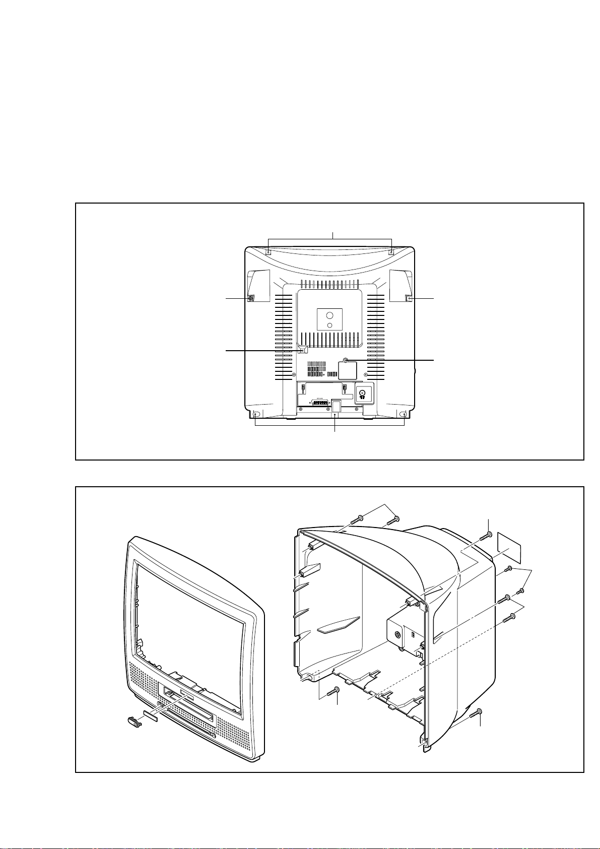
1. Removal of the Rear Cabinet.
Remove seven screws (S-1) and two screws (S-2).
Disconnect connector CN151 and remove the Rear
Cabinet.
Caution !!
Discharge the Anode Lead of the CRT with the CRT
Ground Wire before removing the Anode Cap.
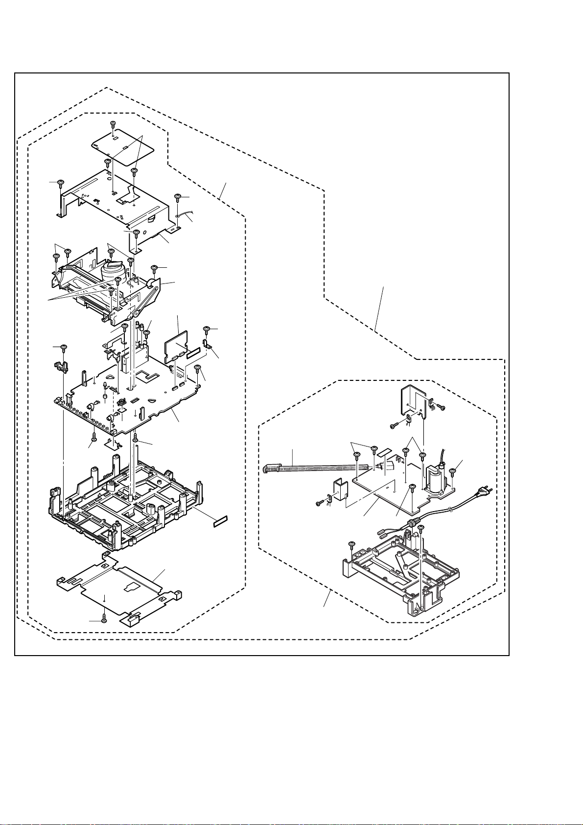
2. Removal of the Power Unit and Tray Chassis Unit.
Discharge the Anode Lead of the CRT with the
CRT Ground before removing the Anode Cap.
Disconnect the following: Anode Cap, CN501,
CN551, CN601, CRT CBA, and Power Knob. Then
pull the Power Unit and Tray Chassis Unit out backward.
3. Removal of the Power Unit.
Disconnect connectors CN502, CN552, and
CN602. Then slide the Power Unit out.
4. Removal of the H.V./Power Supply CBA.
Remove six screws (S-3) and pull up the H.V./
Power Supply CBA.
1-5-1 T6550DC
5. Removal of the Top Cover.
Remove five screws (S-4) and CL604, and remove
the Top Shield.
6. Removal of the Bottom Plate.
Remove a screw (S-5). Then slide the Bottom Plate
out front.
7. Removal of the Deck Unit.
Remove seven screws (S-6), screw (S-7) and
screw (S-8). Then, desolder connectors (CN201,
CL401, CL402, CL403) and lift up the Deck Unit.
S-1 S-1
8. Removal of the Text CBA.
Remove a screw (S-9) and Text Holder, and disconnect connectors CN751 and CN752. Then, lift
the Text CBA up.
9. Removal of the Main CBA.
Remove four screws (S-10) and pull up the Main
CBA.
10.Removal of the CRT.
Remove four screws (S-11) and pull the CRT backward.
S-1
[1] REAR CABINET
S-2
S-2
S-1
Fig. 1
S-1
S-1
S-2
S-1
S-1
S-1
[1] REAR CABINET
1-5-2 T6550DC
Fig. 2
S-4
S-4
[4] Tray
Chassis Unit
S-4
S-6
S-6
S-10
S-7
S-6
S-10
S-4
[6] Top Cover
S-6
[8] Deck Unit
[9] Text CBA
S-10
[10] Main CBA
S-8
CL604
Text
Holder
S-10
S-9
Power Knob
[2] Power Unit and
Tray Chassis Unit
S-3
S-3
S-3
S-5
[7] Bottom Plate
[5] H.V./Power
Supply CBA
[3] Power Unit
S-3
Fig. 3
1-5-3 T6550DC
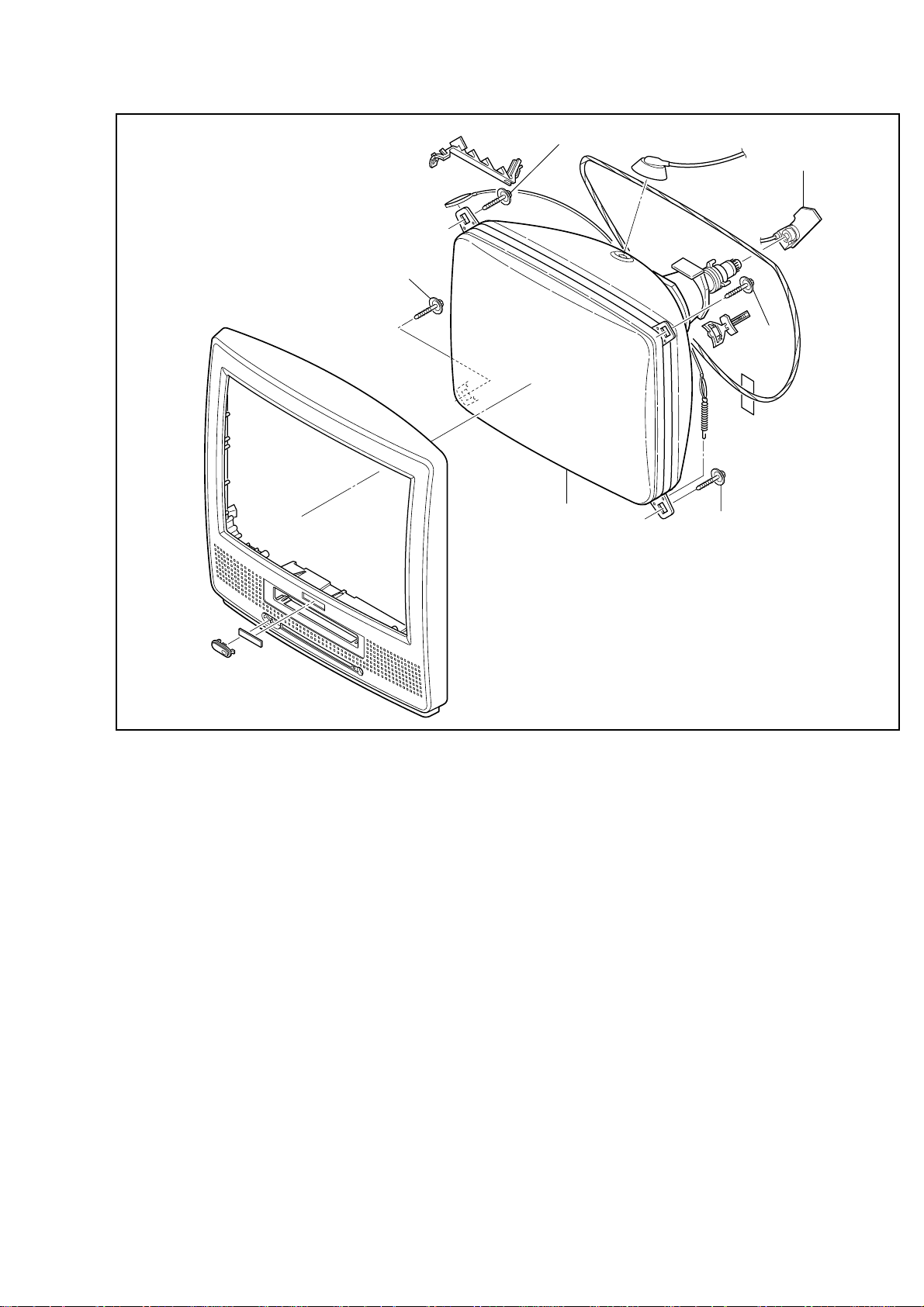
S-11
S-11
Anode Cap
CRT CBA
S-11
[11] CRT
S-11
Fig. 4
1-5-4 T6550DC
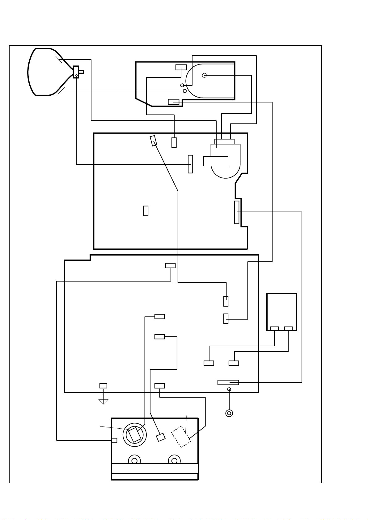
ANODE
CRT
GND
CRT CBA
CN501B
SCREEN
CN502
H.V./POWER SUPPLY CBA
CN552
CL501A
FOCUS
CN501
CN551
MAIN CBA
CN151
CN601
TO DEGAUSS
COIL
CL403
CL401
CL402
CN201
CN751
CL603A
CN602
CL302A
CL301A
CN752
TEXT CBA
CN901
CN902
TO SPEAKER
CYLINDER
ASSEMBLY
FE HEAD
CAPSTAN
ACE HEAD
ASSEMBLY
MOTOR
TO TOP COVER
DECK UNIT
CL604
1-5-5 T6550DC
Fig. 5
ELECTRICAL ADJUSTMENT INSTRUCTIONS
General Note:
"CBA" is abbreviation for "Circuit Board
Assembly."
NOTE:
Electrical adjustments are required after replacing
circuit components and certain mechanical parts.
It is important to perform these adjustments only
after all repairs and replacements have been completed.
Also, do not attempt these adjustments unless the
proper equipment is available.
Test Equipment Required
1. PAL Pattern Generator (Color Bar, Monoscope,
Black Raster, White Raster, Sympte)
2. SECAM Pattern Generator (Gray Scale)
3. AC Milli Voltmeter (RMS)
4. Alignment Tape (9965 000 14514), Blank Tape
(E180)
5. DC Voltmeter
6. Oscilloscope: Dual-trace with 10:1 probe,
V-Range: 0.001~50V/Div,
F-Range: DC~AC-60MHz
7. Frequency Counter
8. Plastic Tip Driver
9. RF input (at each broadcasting system)
Receiving Channel : VHF Low
Input level : 80dBµV
10.Ext.input
FRONT VIDEO-IN JACK or REAR SCART JACK
How to set up the option code
1. Enter the Service mode.
2. Press the [STATUS/EXIT] button on the remote
control unit. The option code appears on the display.
3. If needed, input the option code as shown below
using number buttons on the remote control unit.
Model Option Code
21PV385/07 0176
0178
21PV385/01
0242
21PV385/58 0179
21PV385/39 0177
4. To reset the software, press [PAUSE] and [5] buttons on the remote control unit.
The option code is changed.
How to Set up the Service mode:
NOTE:
After replacing the IC202 (Memory) or Main CBA,
the set value in IC202 (Memory) will be lost. So it
is necessary to set up or adjust in the Service
mode after its replacement.
Service Mode:
1. Turn the power on. (Use main power on the TV
unit.)
2. Press [STANDBY/ON], [2], [7], [1], and [MUTE] buttons on the remote control unit in that order within 5
seconds.
- To cancel the service mode, press [STANDBY/ON]
button on the remote control.
1-6-1 T6550EA
1. DC114V (+B) Adjustment
2. H Adjustment
Purpose: To obtain correct operation.
Symptom of Misadjustment: The picture is dark and
unit does not operate correctly.
Test point Adj. Point Mode Input
TP503
(+B),
TP504
(GND)
Tape M. EQ . Spec .
---
Note: TP503(+B), TP504(GND), VR601 --- H.V./Power
Supply CBA
1. Connect the unit to AC Power Outlet. (exact
AC230V)
2. Input a color bar signal from RF (or Ext.) input and
leave it for at least 20 minutes.
3. Connect DC Volt Meter to TP503(+B) and
TP504(GND).
4. Adjust VR601 so that the voltage of TP503(+B)
becomes +114±0.5V DC.
VR601
DC Voltmeter,
Plastic Tip Driver
RF
(or Ext.)
+114±0.5V DC
Color
Bar
Purpose: To get correct horizontal position and size of
screen image.
Symptom of Misadjustment: Horizontal position and
size of screen image may not be properly displayed.
Test point Adj. Point Mode Input
R590
Tape M. EQ. Spec.
--- Frequency Counter 15.625kHz±75Hz
Note: R590 --- H.V./Power Supply CBA
1. Connect Frequency Counter to R590.
2. Set the unit to the Ext. mode and no input is necessary. Enter the Service mode.
(See page 1-6-10.)
3. Operate the unit for at least 20 minutes.
4. Press [2] button on the remote control unit and
select H-Adj mode.
5. Press [P+/P-] buttons on the remote control unit so
that the display will change [0] to [7.]
At this moment, choose display [0] to [7] when the
Frequency counter display is closest to
15.625kHz±75Hz.
6. Turn the power off and on again.
P+/P-
buttons
Ext. ---
1-6-2 T6550EA
3. C-Trap Adjustment
Purpose: To get minimum leakage of the color signal
carrier.
Symptom of Misadjustment: If C-Trap Adjustment is
incorrect, stripes will appear on the screen.
Test point Adj. Point Mode Input
4. To enter the DSPC mode, press [1] button on the
remote control unit. Recording starts automatically
and “DSPC” appears on the display.
TVCR
DSPC
J349F3
(B-OUT)
Tape M. EQ. Spec.
---
minimum
Note: J349F3 (B-Out)--- Main CBA
1. Connect Oscilloscope to J349F3.
2. Input a color bar signal from RF (or Ext.) input.
Enter the Service mode. (See page 1-6-10.)
3. Press [0] button on the remote control unit and
select C-TRAP mode.
4. Press [P+/P-] buttons on the remote control unit so
that the carrier leakage B-Out (4.43MHz) value
becomes minimum on the oscilloscope.
5. Turn the power off and on again.
P+/P-
buttons
Oscilloscope,
Pattern Generator
Figure
RF
(or Ext.)
200mVp-p Max.
Color Bar
Fig. 1
VIDEO INPUT JACK (Ext. input)
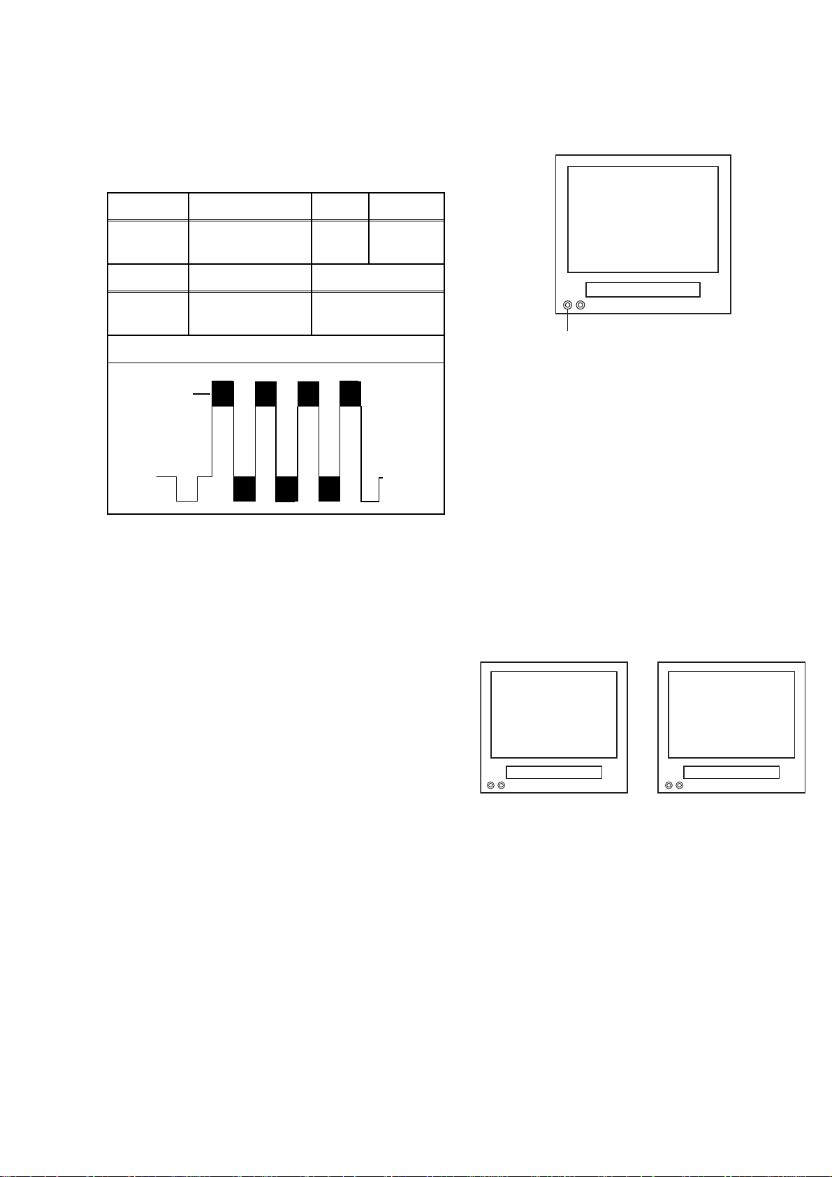
5. Recording continues for 10 seconds in SP mode.
Note: Since the reference value of LP V-ENV is
computed from the reference value of SP V-ENV,
there is no need to survey it.
6. The tape is rewinded to the recording start point.
7. The unit enters the play mode automatically and
the V-ENV levels of each the reference value of SP
mode and the computing value of LP mode are
memorized into the EEPROM.
8. "OK" or "NG" appears on upper left corner of the
screen with blueback.
In case of "OK": "OK" (green) is indicated without
ejecting tape.
In case of "NG": "NG" (red) is indicated with ejecting tape.
l
TVCR TVCR
OK
NG
Fig. 2
4. How to measure the standard
V-ENV value of Digital Studio
Picture Control
Purpose: To set the recording condition appropriate
for the recording tape.
Symptom of Misadjustment: Recording or playing
back picture quality may fall. The picture will be tinted.
1. Insert a new tape (type: E180) for the DSPC alignment into the TV/VCR.
2. Input the black raster signal from the video input
jack (VIDEO-IN).
3. Enter the service mode. (See page 1-6-10.)
Normal
Abnormal
Fig. 3
1-6-3 T6550EA
5. SECAM Black Level Adjustment
6. V. Size Adjustment
Purpose: To set Black Level of the SECAM signal R-
Y/B-Y to Ref. level.
Symptom of Misadjustment: If Black Level of the
SECAM signal R-Y/B-Y is incorrect, the picture is bluish or reddish in grayscale compared with PAL signal.
Tes t
point
J361G4
Tape M. EQ. Spec.
---
Analog Oscilloscope (unus-
able Digital Oscilloscope)
1. Degauss the CRT and allow CRT to operate for 20
minutes before starting the alignment.
2. Input the SECAM Gray Scale signal from Ext.
input.
3. Enter the service mode. (See page 1-6-10.)
4. To enter the C/D/S mode, press [ -] on the
remote control unit.
5. To select SBR (SECAM Black Level R-Y), press [6]
button on the remote control unit.
6. Press [P+/P-] buttons to adjust Y signal to the black
ref. level.
7. To select SBB (SECAM Black Level B-Y), press [7]
button on the remote control unit.
8. Press [P+/P-] buttons to adjust Y signal to the black
ref. level.
Y Signal
Adj. Point Mode Input
P+/P-
buttons
Pattern Generator,
Ext.
SECAM
Gray
Scale
---
Purpose: To obtain correct vertical height of screen
image.
Symptom of Misadjustment: If V. Size is incorrect,
vertical height of image on the screen may not be
properly displayed.
Test point Adj. Point Mode Input
Screen
Tape M. EQ. Spec.
--- Pattern Generator 90±5%
1. Enter the Service mode. (See page 1-6-10.)
Press [9] button on the remote control unit and
select V-S mode. (Press [9] button then display will
change to V-P and V-S).
2. Input monoscope pattern and leave it for at least 20
minutes.
3. Press [P+/P-] buttons on the remote control unit so
that the monoscope pattern is 90±5% of display
size and the circle is round.
P+/P-
buttons
RF
(or Ext.)
Monoscope
7. V. Shift Adjustment
Purpose: To obtain correct vertical position of screen
image.
Symptom of Misadjustment: If V. position is incorrect, vertical position of image on the screen may not
be properly displayed.
Test point Adj. Point Mode Input
Screen
Tape M. EQ. Spec.
P+/P-
buttons
RF
(or Ext.)
Monoscope
1H
Black REF. Level
1H
1H
5mV/Div (10:1 Prove)
Fig. 4
--- Pattern Generator 90±5%
1. Enter the Service mode. (See page 1-6-10.)
Press [9] button on the remote control unit and
select V-P mode. (Press [9] button then display will
change to V-P and V-S).
2. Input monoscope pattern and leave it for at least 20
minutes.
3. Press [P+/P-] buttons on the remote control unit so
that the top and bottom of the monoscope pattern
are equal to each other.
1-6-4 T6550EA
8. H. Shift Adjustment
Purpose: To obtain correct horizontal position and
size of screen image.
Symptom of Misadjustment: Horizontal position and
size of screen image may not be properly displayed.
Test point Adj. Point Mode Input
Screen
Tape M. EQ. Spec.
--- Pattern Generator 90±5%
1. Enter the Service mode. (See page 1-6-10.)
Press [8] button on the remote control unit and
select H-P mode.
2. Input monoscope pattern and leave it for at least 20
minutes.
3. Press [P+/P-] buttons on the remote control unit so
that the left and right side of the monoscope pattern are equal to each other.
4. Turn the power off and on again.
P+/P-
buttons
RF
(or Ext.)
Monoscope
8. To enter the CUT OFF (G) mode, press [2] button
on the remote control unit.
9. Press the [P+/P-] buttons until the horizontal line
becomes white.
10.To enter the CUT OFF (B) mode, press [3] button
on the remote control unit.
11.Press the [P+/P-] buttons until the horizontal line
becomes white.
12.Turn the screen control so that the horizontal line
adjusted white looks lightly.
13.Turn the power off and on again.
9. Cut-off Adjustment
Purpose: To adjust the beam current of R, G, B, and
screen voltage.
Symptom of Misadjustment: White color may be
reddish, greenish or bluish.
Test point Adj. Point Mode Input
Screen
Tape M. EQ. Spec.
--- Pattern Generator
Notes:
Screen Control (FBT) --- H.V./Power Supply CBA
FBT= Fly Back Transformer
Use the Remote Control Unit
1. Degauss the CRT and allow CRT to operate for 20
minutes before starting the alignment.
2. Set the screen control to minimum position. Input
the Black raster signal from RF (or Ext.) input.
3. Enter the service mode. (See page 1-6-10.)
Dimmed horizontal line appears on the CRT.
4. To enter the C/D/S mode, press the [ -] button
on the remote control unit.
5. To enter the CUT OFF (R) mode, press [1] button
on the remote control unit.
6. Turn the screen control up until dimmed horizontal
line appears.
7. Press the [P+/P-] buttons until the horizontal line
becomes white.
Screen-Control,
P+/P- buttonsRF(or Ext.)
Black Ras-
ter
See Reference
Notes below
1-6-5 T6550EA
10. White Balance Adjustment
11. Sub-Brightness Adjustment
Purpose: To mix red, green and blue beams correctly
for pure white.
Symptom of Misadjustment: White becomes bluish
or reddish.
Test point Adj. Point Mode Input
Screen
Tape M. EQ. Spec.
---
Screen-Control,
P+/P- buttonsRF(or Ext.)
Pattern Generator,
Color analyzer
Figure
Color Ajalyzer
See below
White
Raster
(APL 100%)
Fig. 5
Purpose: To get proper brightness.
Symptom of Misadjustment: If Sub-Brightness is
incorrect, proper brightness cannot be obtained by
adjusting the Brightness Control.
Test point Adj. Point Mode Input
Screen
Tape M. EQ. Spec.
---
White
P+/P-
buttons
Pattern
Generator
Figure
RF
(or Ext.)
See below
ABC
SYMPTE
Black
This bar
(A) just
visible
Note: Use remote control unit
1. Operate the unit more than 20 minutes.
2. Face the unit to east. Degauss the CRT using Degaussing Coil.
3. Input the White Raster (APL 100%).
4. Set the color analyzer to the CHROMA mode and
after zero point calibration, bring the optical receptor to the center on the tube surface (CRT).
5. Enter the Service mode. Press [ -] button on the
remote control.
6. Press [4] button on the remote control unit for Red
adjustment. Press [5] button on the remote control
unit for Blue adjustment.
7. In each color mode, Press [P+/P-] buttons to adjust
the values of color.
8. Adjusting Red and Blue color so that the temperature becomes 8500K (x : 290 / y : 300) ±3%.
9. At this time, Re-check that Horizontal line is white.
If not, Re-adjust Cut-off Adjustment until the Horizontal Line becomes pure white.
10. Turn off and on again to return to normal mode. Receive APL 100% white signal and Check Chroma
temperatures become 8500K (x : 290 / y : 300) ±3%.
Note: Confirm that Cut Off Adj. is correct after this
adjustment, and attempt Cut Off Adj. if needed.
Fig. 6
Note: Bar (A) in Fig. 7 --- 0 IRE
1. Enter the service mode. (See page 1-6-10.)
Then input SYMPTE signal from RF (or Ext.) input
and leave it for at least 20 minutes.
2. Press [MENU] button. (Each time [MENU] button is
pressed, display will change BRT, CNT, COL, TNT,
and SHP in that order.) Select BRT and press [P+/
P-] buttons so that the bar (A) in Fig. 6 is just visible.
3. Turn the power off and on again.
1-6-6 T6550EA

12. Setting for CONTRAST,
COLOR, TINT and SHARP
Data Values
General
1. Enter the Service mode. (See page 1-6-10)
2. Press [MENU] button. (Each time [MENU] button is
pressed, display will change BRT, CNT, COL, TNT,
and SHP in that order.)
CONTRAST (CNT)
1. Press [MENU] button on the remote control unit.
Then select CNT display.
2. Press [P+/P-] buttons on the remote control unit so
that the value of "CONTRAST" (CNT) becomes 83.
COLOR (COL)
1. Press [MENU] button on the remote control unit.
Then select "COLOR" (COL) display.
2. Press [P+/P-] buttons on the remote control unit so
that the value of "COLOR" (COL) becomes 65.
TINT (TNT)
1. Press [MENU] button on the remote control unit.
Then select "TINT" (TNT) display.
2. Press [P+/P-] buttons on the remote control unit so
that the value of "TINT" (TNT) becomes 68.
13. Focus Adjustment
Purpose: Set the optimum Focus.
Symptom of Misadjustment: If Focus Adjustment is
incorrect, blurred images are shown on the display.
Test point Adj. Point Mode Input
Screen Focus Control
Ta p e M. EQ . Sp ec .
--- Pattern Generator See below.
Note: Focus VR (FBT) --- H.V./Power Supply CBA
FBT= Fly Back Transformer
1. Operate the unit more than 30 minutes.
2. Face the unit to the East and degauss the CRT
using a Degaussing Coil.
3. Input the monoscope pattern.
4. Adjust the Focus Control on the FBT to obtain clear
picture.
RF
(or Ext.)
Monoscope
SHARP (SHP)
1. Press [MENU] button on the remote control unit.
Then select "SHARP" (SHP) display.
2. Press [P+/P-] buttons on the remote control unit
and select "0."
1-6-7 T6550EA

14. Head Switching Position Adjustment
Purpose: Determine the Head Switching Point during
Playback.
Symptom of Misadjustment: May cause Head
Switching Noise or Vertical Jitter in the picture.
Note: Unit reads Head Switching Position automatically and displays it on the screen (Upper Left Corner).
Manual Adjustment
1. Enter the service mode. (See page 1-6-10.)
2. Playback the test tape (9965 000 14514).
3. Press the number [5] button on the remote control
unit.
4. The Head Switching position will display on the
screen; if adjustment is necessary follow step 4.
7.0H (448µs) is preferable.
5. Press [P+/P-] buttons on the remote control unit if
necessary. The value will be changed in 0.5H steps
up or down. Adjustable range is up to 9.5H. If the
value is beyond adjustable range, the display will
change as:
Lower out of range: 0.0H
Upper out of range: -.-H
6. Turn the power off and on again.
Auto Adjustment
1. Load the test tape (9965 000 14514) that have
been recorded the Head Switching Position Value.
2. Enter the service mode.
3. Press [3] button on the remote control unit in the
tape stop mode. The unit playback and adjust the
Head Switching Position automatically.
4. The adjusting report appears on upper left corner
of the screen with blueback.
In case of adjusting correctly: the Head Switching
Position Value recorded in the test tape (9965 000
14514) is indicated with green.
In case of adjusting incorrectly: "NG" (red) is indicated with ejecting tape.
l
TVCR TVCR
7.0H
NG
Correct
Incorrect
Fig. 7
1-6-8 T6550EA
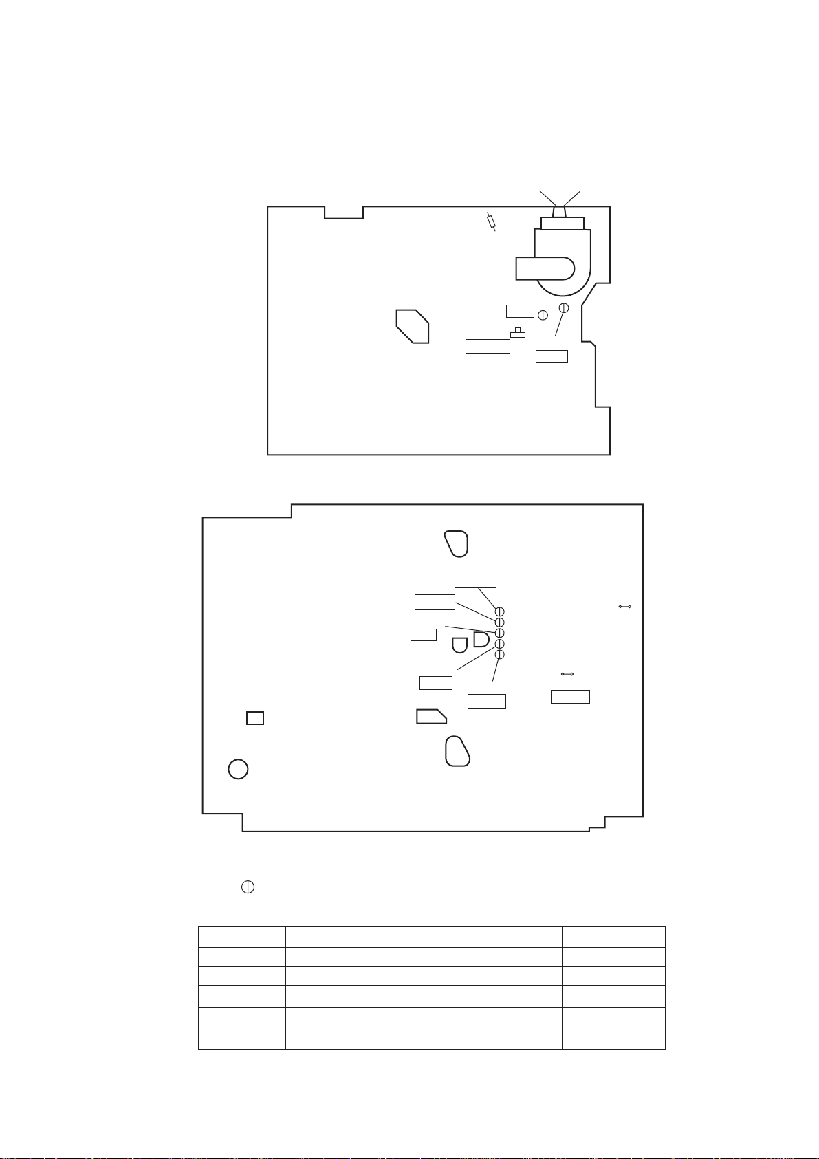
Adjustment Points and Test Points
H.V./Power Supply CBA Top View
Focus-control (Upper side)
R590
(H Adjustment)
VR601
+B ADJ
Main CBA Top View
TP007
N-A-PB
TP002
RF-SW
TP001
CTL
Screen-control (Lower side)
TP503
+B
TP504
GND
J361G4
(SECAM
Black Level
Adjustment)
TP008
IC202
C-PB
TP003
V-OUT
J349F3
B-OUT
TEST POINT INFORMATION
: Indicates a test point with a jumper wire across a hole in the PCB.
TEST POINTS NOT USED IN ELECTRICAL ADJUSTMENTS
Test Point
TP001
TP002
TP008
TP503
TP504
Mechanical Alignment Procedures
Mechanical Alignment Procedures
Mechanical Alignment Procedures
Electrical Adjustment Instructions
Electrical Adjustment Instructions
Used in: Page No.
2-3-3
2-3-3, 2-3-4
2-3-3, 2-3-4
1-6-1
1-6-1
1-6-9 T6550EA
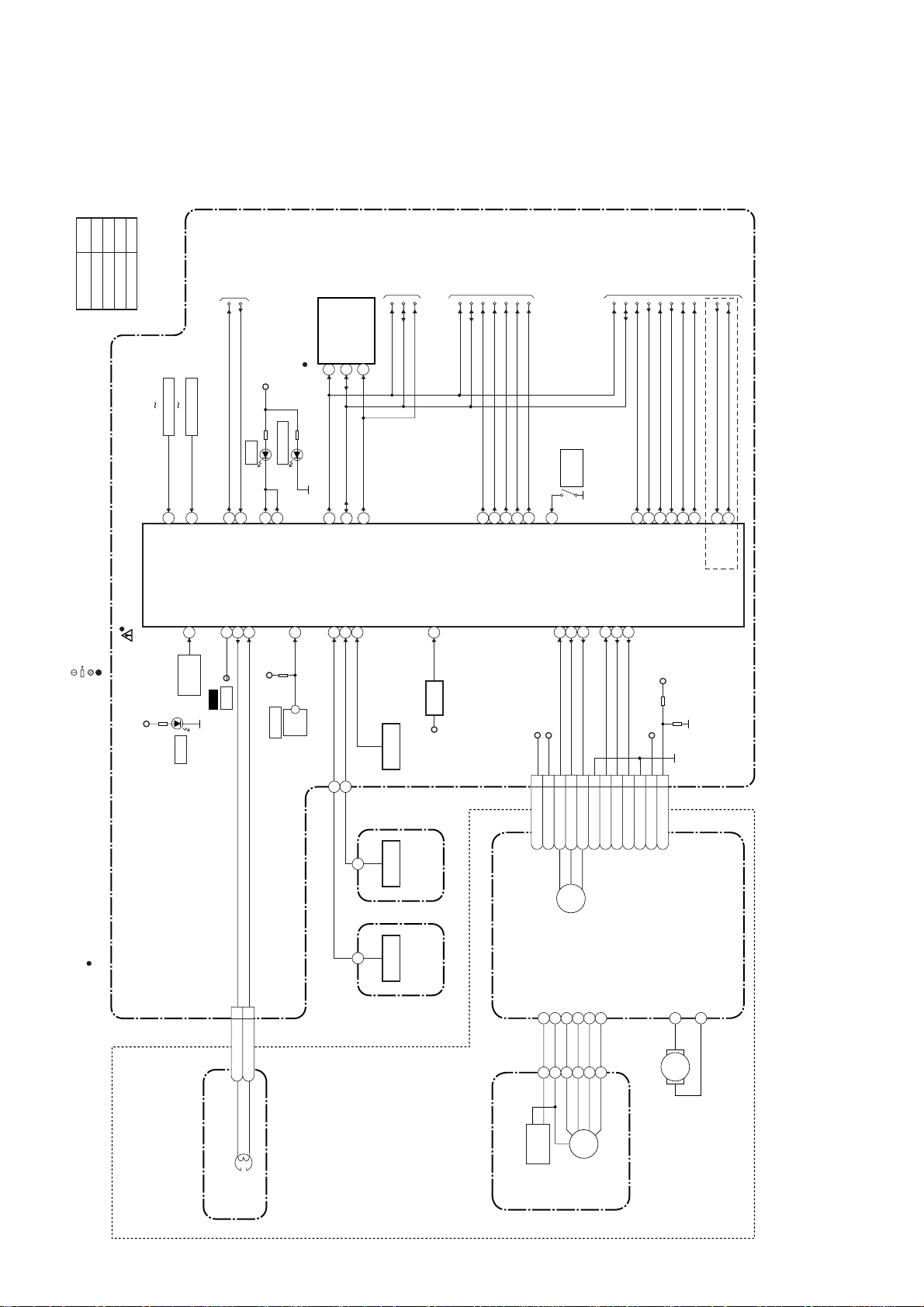
BLOCK DIAGRAMS
Servo/System Control Block Diagram
A
B
C
D
TO POWER
Model Mark
21PV385/07
Comparison Chart of
Models & Marks
21PV385/01
21PV385/58
21PV385/39
SUPPLY BLOCK
P-ON-H
P-DOWN-L
AL+5V
(MEMORY)
SCL
IC202
6
SDA
5
CS
7
TO CHROMA
SCL
SDA
BLOCK
C-OPEN
2
I
SCL
SDA
SP-MUTE
TO AUDIO
BLOCK
EXT-L
SCART-H
A-MUTE-H
SCART-MUTE
SCL
SDA
C-SYNC
D-REC-H
TO VIDEO
BLOCK
V-ENV
C-ROTA
DV-SYNC
RF-SW
TRICK-H
SECAM-H
THE PCB.
WITH A COMPONENT LEAD ON FOIL SIDE.
:INDICATES A TEST POINT WITH A JUMPER WIRE ACROSS A HOLE IN
:USED TO INDICATE A TEST POINT
:USED TO INDICATE A TEST POINT WITH NO TEST PIN.
:USED TO INDICATE A TEST POINT WITH A TEST PIN.
TEST POINT INFORMATION
OR.
.)
KEY SWITCH
SW201 SW205
7
KEY-1
IC201
(SERVO/SYSTEM CONTROL)
RS201
AL+5V
D201
KEY SWITCH
SW206 SW210
8
KEY-2
P-ON-H
CTL AMP-OUT
REMOTE
14
97
TP001
REMOTE
SENSOR
CTL
WF3
S-LED
85
67
P-DOWN-L
CTL(+)
95
D202 REC
CTL(-)
94
D204 STANDBY
24
23
REC-LED
REC-LED
AL+5V
LD-SW
SW212
LD-SW
9
72
71
SCL
SDA
ST-SENS.
END-SENS.
10480
45
C-OPEN
2
I
T-REEL
Q205Q201
T-REEL
RESET
34
Q204
RESET
TIMER+5V
424829
20
44
EXT-L
SP-MUTE
A-MUTE-H
SCART-H
SCART-MUTE
CM+12V
1CM+12V
CN201
REC
SAFETY
SW211
31
REC-SAFETY
C-CONT
C-F/R
C-FG
76
78
87
P-ON+5V(3)
4C-F/R
2P-ON+5V(3)
3C-FG
5
C-CONT
LD-CONT81D-CONT
6FG-GND
7LD-CONT
D-PFG
77
90
8D-CONT
9
D-PFG
74
47
C-SYNC
D-REC-H
AL+12V(1)
10M-GND
11AL+12V(1)
6
15
13
V-ENV
C-ROTA
DV-SYNC
+33V
12VG
18
RF-SW
D
32
33
TRICK-H
SECAM-H
NOTE FOR WIRE CONNECTORS:
1. PREFIX SYMBOL "CN" MEANS CONNECT
(CAN DISCONNECT AND RECONNECT
2. PREFIX SYMBOL "CL" MEANS WIRE-SOLDER
HOLES OF THE PCB.
(WIRE IS SOLDERED DIRECTLY.)
MAIN CBA
" " = SMD
)
ASSEMBLY
(DECK
CL402
1CTL(-)
2CTL(+)
AC HEAD ASSEMBLY
CONTROL
HEAD
END-SENS.
ST-SENS.
Q202
1-7-1
SENSOR CBA
(END-SENSOR)
SENSOR CBA
(ST-SENSOR)
M
CAPSTAN
PG
SENSOR
MOTOR
M
DRUM
MOTOR
CAPSTAN MOTOR
CYLINDER ASSEMBLY
M
LOADING
MOTOR
T6550BLS
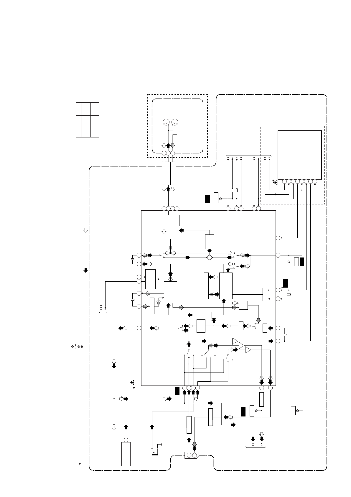
Video Block Diagram
A
B
D
C
VIDEO (L)
VIDEO (R)
HEAD
HEAD
Model Mark
21PV385/07
21PV385/01
21PV385/58
Comparison Chart of
Models & Marks
21PV385/39
(DECK ASSEMBLY)
THE PCB.
REC-VIDEO SIGNAL PB-VIDEO SIGNAL MODE: SP/REC
WITH A COMPONENT LEAD ON FOIL SIDE.
WITH A TEST PIN.
SDA
SCL
TO
SERVO/SYSTEM
:INDICATES A TEST POINT WITH A JUMPER WIRE ACROSS A HOLE IN
:USED TO INDICATE A TEST POINT
:USED TO INDICATE A TEST POINT WITH NO TEST PIN.
:USED TO INDICATE A TEST POINT
CONTROL BLOCK
7978
69684643
65
CYLINDER ASSEMBLY
123
V(L)
V(R)
CL401
V-COM
969593
SP
HEAD
AMP
P
R
SERIAL
DECORDER
LUMINANCE
SIGNAL
PROCESS
Y. DELAY
94
AGC
BYPASS
WF1
REC FM
+
Y
CCD 1H DELAY
CHARA.
INS.
TP002
AGC
C
1/2
RF-SW
RF-SW
C-ROTA
D-REC-H
DV-SYNC
70
80
D-REC-H
RF-SW/C-ROTA
RPRP
CHROMINANCE
SIGNAL
PROCESS
D
TO SERVO/SYSTEM
CONTROL BLOCK
V-ENV
C-SYNC
67
84
62
V-ENV
C-SYNC
DV-SYNC
Y/C
MIX
PR
FBC
TRICK-H
SECAM-H
IC471 (PAL/SECAM DECTECOTR)
28
PB-H OUT
21
2928 44
AGC VXO
58 59
WF2
1
29
C-PB
TP008
X401
4.43MHz
PAL/SECAM
DETECTOR
17
12216
14
WF6
TEST POINT INFORMATION
OR.
.)
WIRE-SOLDER
C-VIDEO
NOTE FOR WIRE CONNECTORS:
1. PREFIX SYMBOL "CN" MEANS CONNECT
(CAN DISCONNECT AND RECONNECT
2. PREFIX SYMBOL "CL" MEANS
HOLES OF THE PCB.
(WIRE IS SOLDERED DIRECTLY.)
TO
CHROMA
MAIN CBA
" " = SMD
BLOCK
TU001
IC401
(VIDEO/AUDIO SIGNAL PROCESS)
24
VIDEO OUT
JK701
V-IN
WF4
TUNER
SCART
485254
Q705
JK703
LINE
BUFFER
20
19
V-IN
V-OUT
1-7-2
SCART
56
LINE
PB/EE
BUFFER
Q703
MUTE
TUNER
PB/EE
MUTE
WF5
V-OUT
TP003
TU-VIDEO
61
BUFFER
Q401
VIDEO
TO CHROMA
BLOCK
63
GND
TP010
T6550BLV
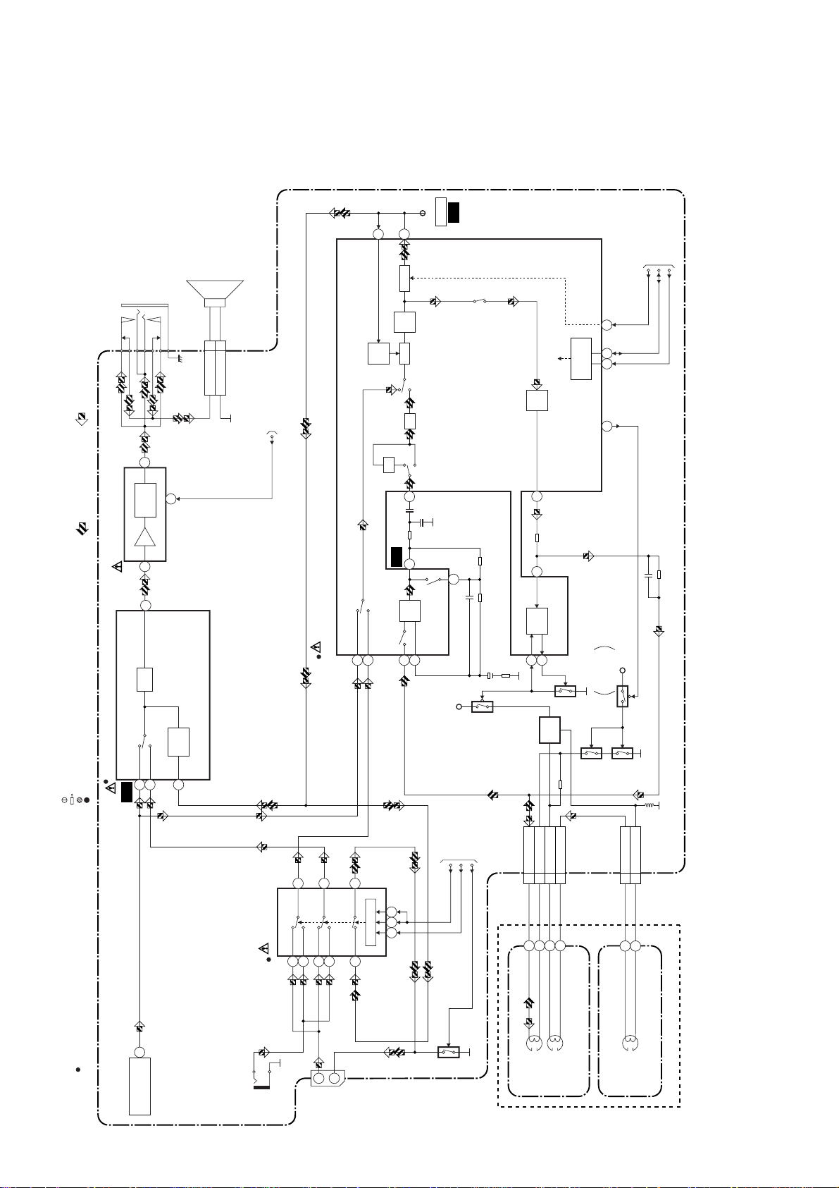
Audio Block Diagram
SP151
JK151
Mode : SP/REC
PB-AUDIO SIGNAL REC-AUDIO SIGNAL
HEADPHONE JACK
1
AMP
OUTPUT
MUTE
CL801
CN151
SP1SP-GND 2
5
SPEAKER
TO
SERVO/SYSTEM
CONTROL BLOCK
SP-MUTE
ALC
WF8
N-A-PB
TP007
11
12
TO
SERVO/SYSTEM
CONTROL BLOCK
DET
INV
LINE
R
MUTE
AMP
ALC
ATT
98
SERIAL
DECODER
AUDIO HD-SW
CONTROL
71
68 69
16
REC-ON
P
REC
AMP
100
SCL
SDA
A-MUTE-H
IC151 (AMP)
7
MAIN CBA
THE PCB.
50
WITH A COMPONENT LEAD ON FOIL SIDE.
:INDICATES A TEST POINT WITH A JUMPER WIRE ACROSS A HOLE IN
:USED TO INDICATE A TEST POINT
:USED TO INDICATE A TEST POINT WITH NO TEST PIN.
:USED TO INDICATE A TEST POINT WITH A TEST PIN.
TEST POINT INFORMATION
OR.
.)
WIRE-SOLDER
ATT
(VIDEO/AUDIO/CHROMA/DEFLECTION/IF)
LINE
TUNER
IC301
52
53
WF7
AUDIO
54
MUTE
IC701 (SW)
WF9
7
EQ
AMP
SP/LP-ON
PB-ON
TUNER
LINE
IC401
(AUDIO SIGNAL PROCESS)
13
4
14
SCART
LINE
SCART
LINE
1
2155
3
12
17
SW CTL
5
6
+5V
Q854
TO SERVO
/SYSTEM
CONTROL
BLOCK
EXT-L
SCART-H
1011 9
SCART-MUTE
CL402
3 A-PB/REC
3
AUTO
1
Q855
BIAS
2
BIAS
OSC
4 A-COM
6 AE-H/FE-H
Q856
Q853(PB=ON)
5 FE-H
+5V
SWITCHING
D-REC-OFF
Q851
CL403
1 FE-H
Q852(PB=ON)
2 FE-H-GND
NOTE FOR WIRE CONNECTORS:
1. PREFIX SYMBOL "CN" MEANS CONNECT
(CAN DISCONNECT AND RECONNECT
2. PREFIX SYMBOL "CL" MEANS
HOLES OF THE PCB.
(WIRE IS SOLDERED DIRECTLY.)
21
" " = SMD
AUDIO OUT
TU001
JK702
A-IN
JK703
2
A-IN
1
A-OUT
1-7-3
Q701
AUDIO
HEAD
AUDIO
ERASE
HEAD
(DECK ASSEMBLY)
FE HEAD
ACE HEAD ASSEMBLY
FULL
ERASE
HEAD
T6550BLA
 Loading...