

Page 1
PFAFF
246
®
Service
Innovation
Nr.
296-12-1^
552
Manual
mode
by
PFAFF
engl.
9/89
Page 2
Notes
The
machine
If
it
observed.
Service-
Apart
is
not
CONTENTS
on
safety
is
converted
.
and
from
exceptions
permitted.
must
repair
only
to
be
used
another
work
must
according
for
the
version,
only
be
to
DIN
purpose
all
valid
carried
57 105 and
it
out
was
designed
safety
by
qualified
VDE
0105, work on
for.
regulations
personnel.
Page
must
live
be
parts
11
12
10
1
2
3
4
5
6
7
8
Positioning the feed dog
Preliminaryadjustment of feed lifting
Centering the needle in the needle hole
Topand bottom feed advancing motions
Hook
timing,
hook-to-needle clearance and
Needle guard
Final adjustment of feed lifting
Clearance
between
presser
foot
motion
and
needle
motion
needle
plate
bar
height
4
7
8
9
10
12
13
14
(-706/35; -706/47and -706/48)
9
Top-to-bottom-feed timing
Top feed lifting motion
Bobbin
Tension
case opener
release
mechanism
15
16
17
18
13
14
15
Threadcheck
Bobbin
winder
Final worksteps
spring
19
20
21
Page 3
Instructions for adjusting Pfaff
245,
1245
and
1246 machines
Note:
Technical
Needle
Needle
Top
feed lift: 5
data
system:
bar
rise:
All illustrations in this book apply to Pfoff 245 and 1245 single-needle
machines. On Pfaff 246 and 1246 two-needle machines various adjustments
have to be mode
effect;
some
twice.
The respective sections contain a note to this
of the illustrations in these sections apply in reflex.
134-35 on subcl. -706/05, -706/07 and -706/35
134 on subcl. -706/25
190
ModelsAand
Models B/C and C =
Models C/D and D =
7
5
5.5
8.0
• on subcl.-706/47 and-706/48
B
=1.6
mm
2.0
mm
2.2-2.5
mm
on subcl. -706/05
mmonsubcl.
mm
on subcl. -706/25
mm
on subcl. -706/35
mm
on subcl. -706/48
-706/07
and
mm
-706/47
Max.
clearance
between
presser
foot
and
needle
plate:14mm*
Tools, gauges and other items needed for adjustment
Setofscrewdrivers
Set of alien keys ranging
Set of spanners from 7 to 14
C-clomp, No. 08-880 137-00
Gauge,
Metal
Sewing
No.
rule
thread and material for testing
En
machines equipped with knee lifter or subcl. -910/04.
08-880
with
136-14
blades
from
mm
from 2to10 mm
2 to 6
mm
wide
purposes
wide
Page 4
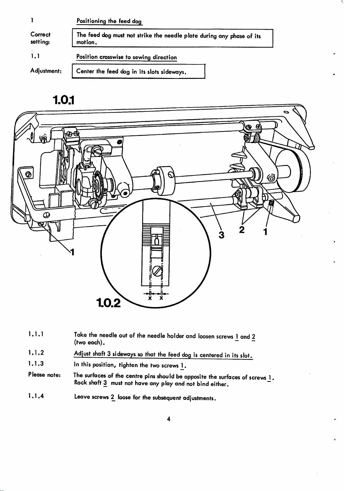
1
Positioning the feed dog
Correct
setting:
1.1
Adjustment:
The
feed
dog
must
not
strike
the
needle
motion.
Position crosswise to sewing direction
Center the feed
dog
in its
slots
sideways.
plate
during
any
phaseofits
1.1.1
1.1.2
1.1.3
Please
1.1.4
note:
Take
the
needle
(two each). ~ ~
Adjust
In this
The
Rock
Leave
shaft3sidewayssothat the
|X}sition,
surfacesofthe
shaft3must
screws^loose
outof the
tighten the
centre
not
have
for
the
needle
holder
feed
two
screws
pins
shouldbeopposite
any
play
and
subsequent
and
loosen
screws
dogiscentered
1.
the
not
bind
either.
adjustments.
1and 2
in itsslot.
surfacesofscrews
1
""
Page 5
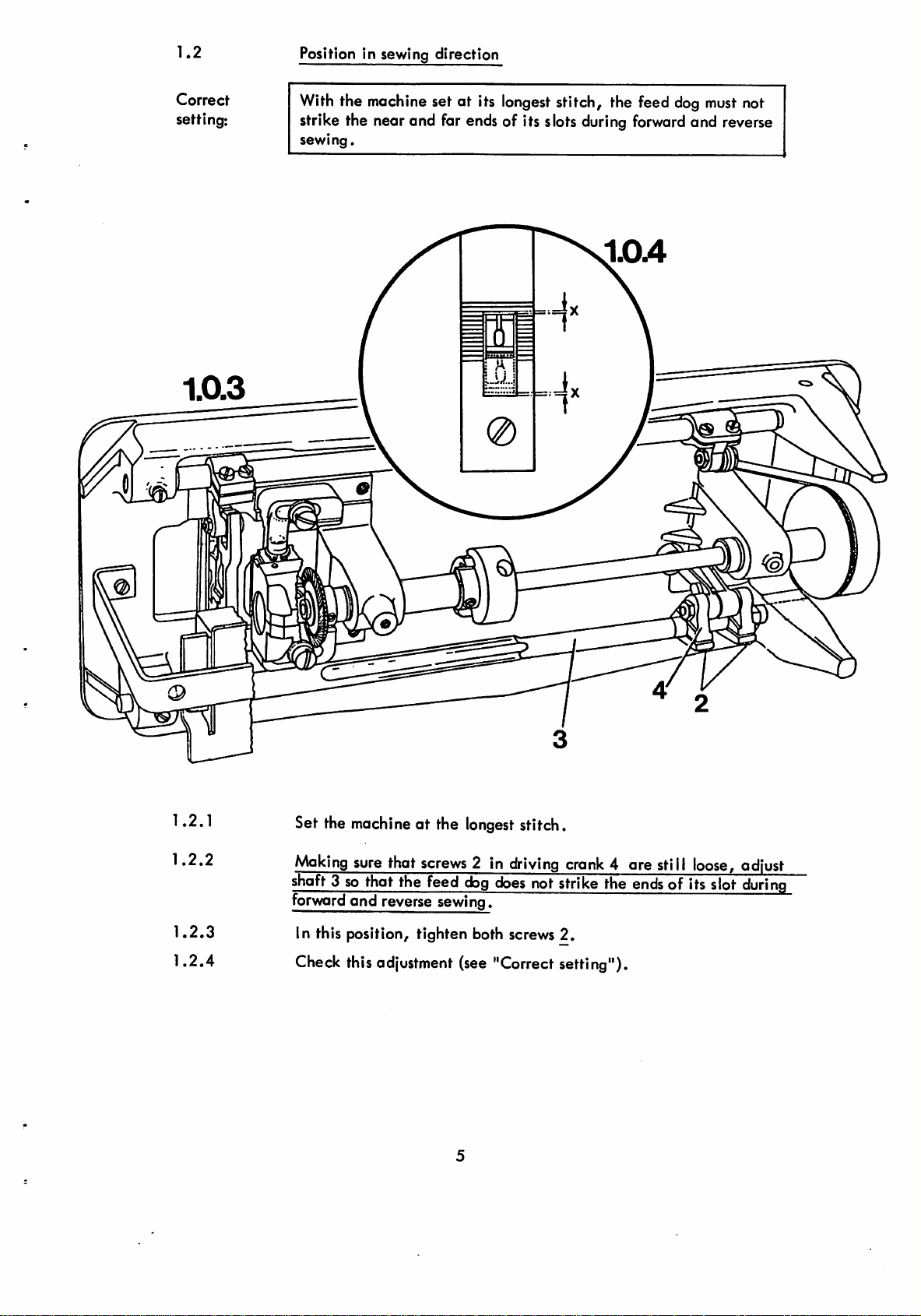
1.2
Position in sewing direction
Correct
setting:
With
the
machine
set at its
longest
stitch, the feed
strike the near and far ends of its slots
sewing.
0
during
forward
dog
must
and reverse
not
1.2.1
1.2.2
1.2.3
1.2.4
Set the machine at the longest stitch.
Making
shaft3 so that the feed
forward
In this position, tighten both screws 2.
sure
that
screws
2 in
dog
and reverse sewing.
driving
does
notstrike the
crank
Check this adjustment (see "Correct setting").
4 ore still
ends
of its slot
loose,
adjust
during
Page 6
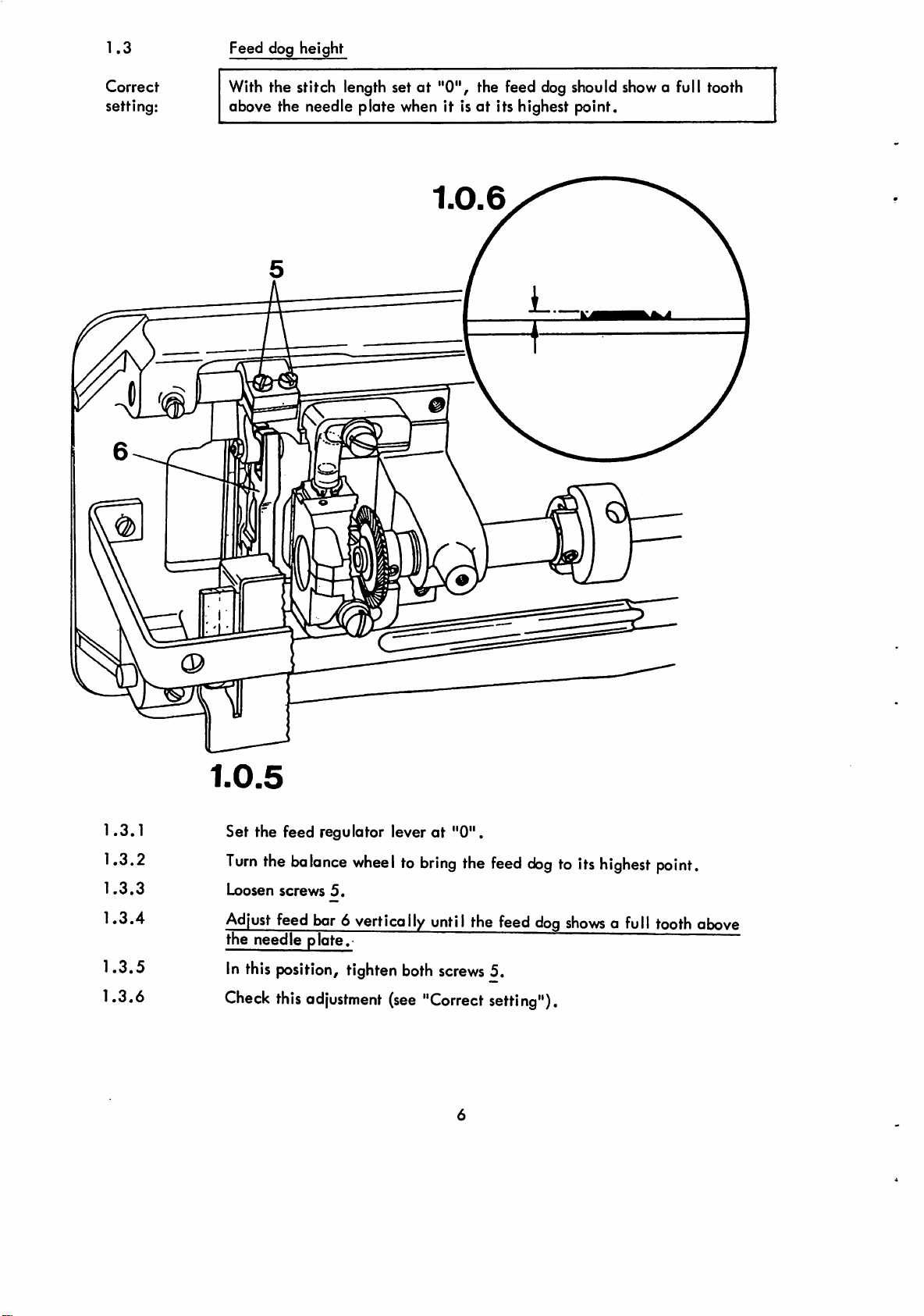
1.3
Feed dog height
Correct
setting:
With the stitch length setat"0",
above the needle plate when it isatits highest point.
the feed dog should show a full tooth
1.3.1
1.3.2
1.3.3
1.3.4
1.3.5
1.3.6
1.0.5
Set
the feed regulator leverat"0".
Turn
the
balance
Loosen
Adjust
the needle plate.
In this position, tighten both
Check
screws
feed bar 6 vertically until the feed
this
wheeltobring
5.
adjustment
(see
the
screws
"Correct
feed
dogtoits
dog
5.
setting").
highest
shows
a full tooth above
point.
Page 7
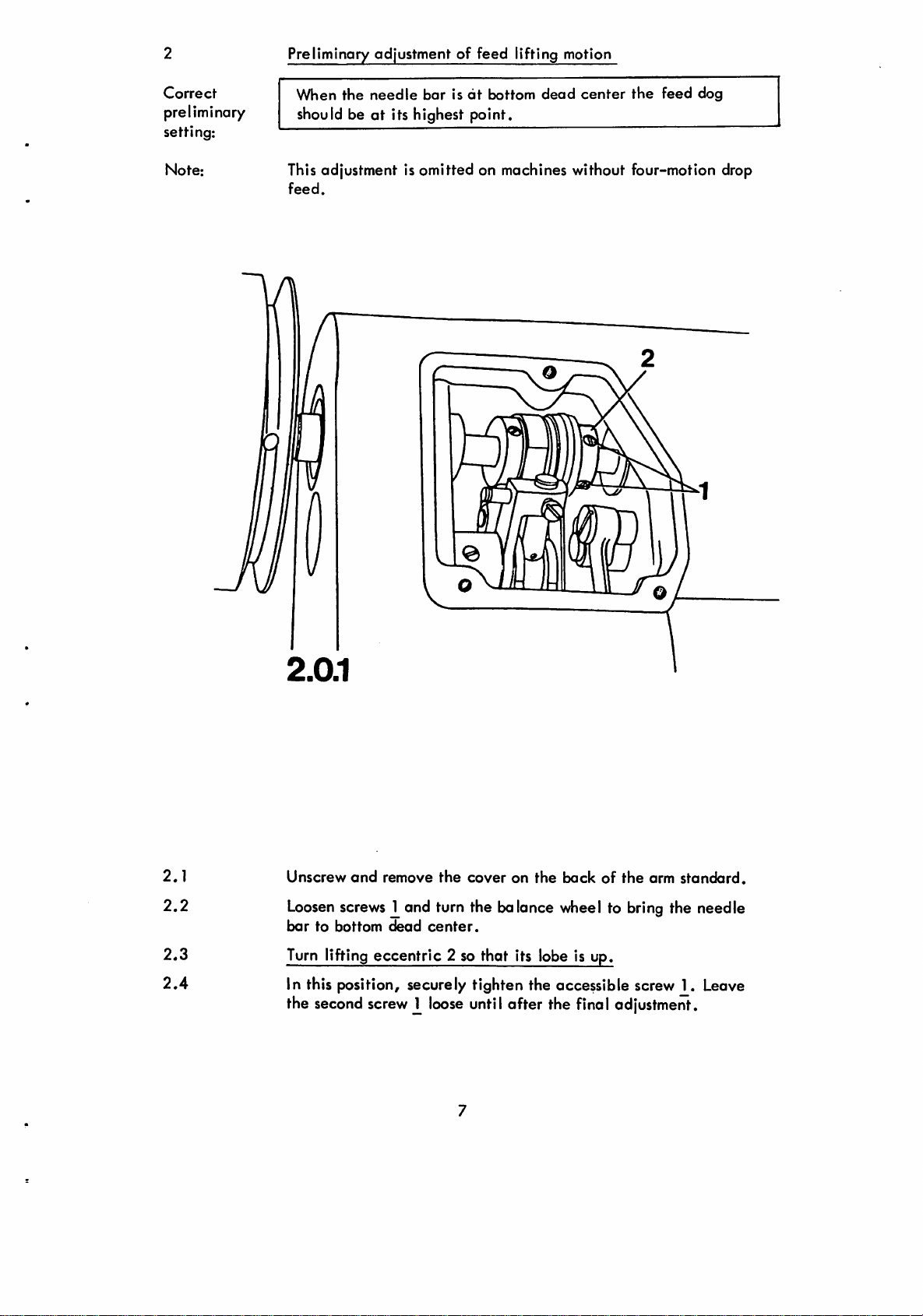
Preliminary adjustment of feed lifting motion
Correct
preliminary
setting:
Note:
When
the
needle
barisdt
bottom
dead
center
the
feed
dog
should beatits highest point.
This adjustment is omitted on machines without four-motion drop
feed.
2.1
2.2
2.3
2.4
©
Unscrew
Loosen
bartobottom
Turn lifting
and
screws
remove
the
coveronthe
bockofthe
arm
and turn the balance wheel to bring the needle
dead
center.
eccentric
2 so that its lobe is up.
standard.
In this position, securely tighten the accessible screw 1. Leave
the
second
screw^loose
until
after the
final
adjustment.
Page 8
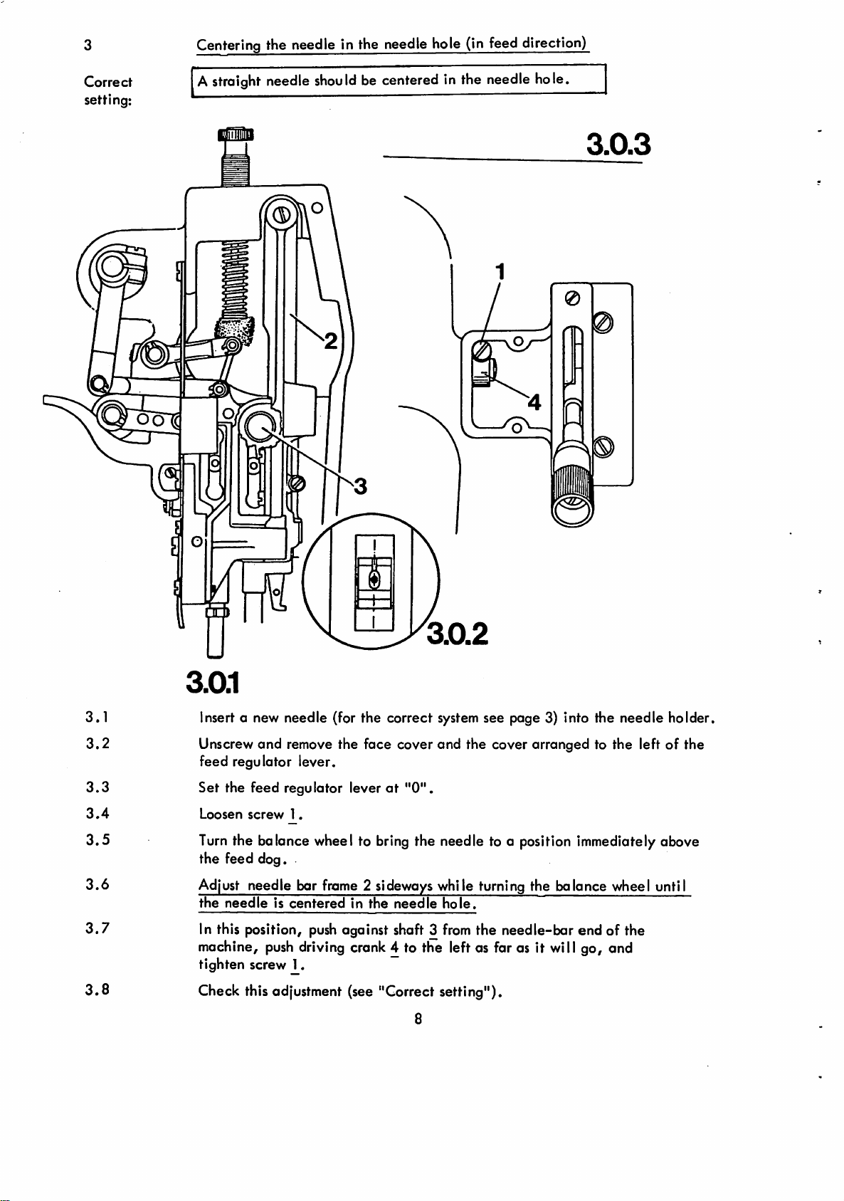
Centering the needle in the needle hole (in feed direction)
Correct
setting:
OOT(
Astraight needle
should
be centered in the needle hole.
3.0.3
0
3.1
3.2
3.3
3.4
3.5
3.6
3.7
3.8
3.0.1
Insert a new needle (for the correct
Unscrew
and
remove the face cover and the cover arranged to the left of the
feed regulator lever.
Set the feed regulator lever
Loosen
Turn
screw
1.
the balance wheel to
at
bring
the feed dog.
Adjust needle bar
the
needleiscentered
In this position,
machine,
push
frome
2 sideways while turning the balance wheel until
in
the
needle
push
against shaft 3
driving crank 4 to the left as far as it will go, and
tighten screw 1.
Check this adjustment (see "Correct setting").
system
"0".
the needle to a position immediately above
hole.
from
8
see page 3) into the needle holder.
the needle-bar end of the
Page 9

Top and bottom feed advancing motions
Correct
setting:
With the machine set for its longest stitch and the needle bar
positionedatbottom dead center the top and bottom feeds should
remain
motionless
when
the feed regulator lever is operated.
4.1
4.2
4.3
4.4
4.5
4.6
4.0.1
Set the machine for its longest stitch.
Loosen
to be turned on its shaft against resistance. ~
Bring the needle bar to bottom dead
Position
(without disturbing the above setting) and turn
direction until the top and bottom feeds remain completely
when the feed regulatior lever is operated.
In this position, tighten screws 1.
Check this adjustment (see "Correctsetting").
screws2just
the
eccentric
sufficiently toallow
center.
lobeoffeed
advancing
feed
advancing
eccentric
just
2 "down"
lightly in feeding
eccentric 2
motion
less
Page 10
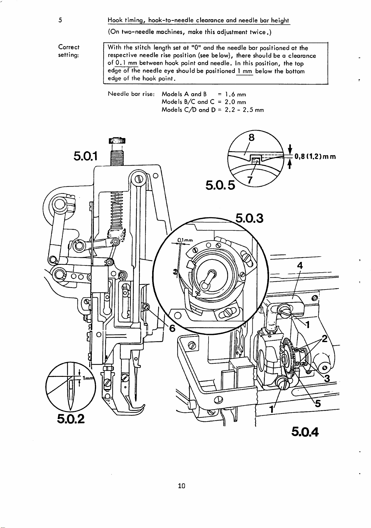
Hook timing, hook-to-needle clearance and needle bar height
Correct
setting:
(On two-needle machines,
With
the stitch
length
moke
this adjustment twice.)
set at "0" and the needle bar positioned at the
respective needle rise position (see below), there should be a clearance
of 0.1
edge of the needle eye should be positioned 1
edge of the hook
Needle
mm
bar
between
rise:
hook
point and needle. In this position, the top
point.
ModelsAand
Models
Models
B/C
C/D
B
and
C =
and D =
=1.6
2.0
2.2-2.5
mm
below the bottom
mm
mm
mm
0,8
(1.2)nim
m
10
Page 11

5.1
Make sure o new
length at
"0".
needle
has been inserted, then set
the
stitch
5.2
5.3
5.4
Unscrew
Loosen
and
remove needle
screws^cmd
2 as
well
plate
as the
and
screws
feed dog.
of collar3.
Turn the balance wheel and bevel gear 5 until the hook point is
positioned in the middle of the needle scarf.
5.5
5.6
5.7
5.8
5.9
5.10
5.11
Adjust hook bracket 4 sideways until there is a clearance of 0.1
between hook point
In this position, tighten screws
Turn bevel
those on the large bevel gear.
Push
gear
bevel gear 5 up against the small bevel gear so that both gears are
neither set too close nor hove too
and
needle.
5 to set the marks of the small bevel gear between
much
play.
mm
In this position, move collar 3 up against bevel gear 5 and tighten the
screwsinthe
Turn the balance wheel to bring the needle bar to bottom dead
Push
the appropriate blade of the needle rise gouge (see needle rise data)
onto the needle bar immediately below its lower bearing, push the
collar.
center.
C-clamp up against the blade and tighten its screw.
5.12 Pull out the gauge blade and turn the balance wheel until the C-clamp
contacts the needle bar bearing.
5.13
5.14
5.15
5.16
5.17
5.18
5.19
Note:
Turn bevel gear 5 until the hook point is opposite the center line of the
needle.
In this position, tighten the accessible screw 2.
Remove
Making sure that the hook point is still positioned opposite the center
line of the
until the bottom
top edge of the needle
In this position, tighten screw6,making sure that the needle scarf
faces the hook point.
Turn the
tighten
the
C-clamp
needle,
balance
it.
from the needle bar.
loosen screw 6
edgeofthe
eye.
wheel until the second screw 2 is accessible, then
and
adjust the needle bar
hook point is positioned
1.0
vertically
mm
above
Check this adjustment (see "Correct setting").
When
exchangingahook
and the cutoutof needle plate 8 the
Models A andB:roughly
Models C and D: roughly 1/2mm
bracket
0,8
mm
make
sure
following
(see Fig.
that
between
clearancesare
5.0.5.)
position
kept:
lug
If necessary, correct hook height by inserting respective washers.
the
7
On NIO machines, make this adjustment with the machine set
at
its longest
stitch.
11
Page 12
Needle
(On two-needle machines, make this adjustment twice.)
guard
Correct
setting:
Requirement: The hook-to-needle clearance
When
the
needle
should contact the needle just lightly, thus preventing the needle
striking the hook point.
bar is at the needle
rise
position, needle
must
have been set correctly.
guard
^
6.1
6.2
6.0.1
Turn
the balance
Adjust needle guard 1 so that it contacts the needle just lightly, however
without
deflecting
wheeltobring
it.
the needle to the
q.eedle
rise position.
12
Page 13
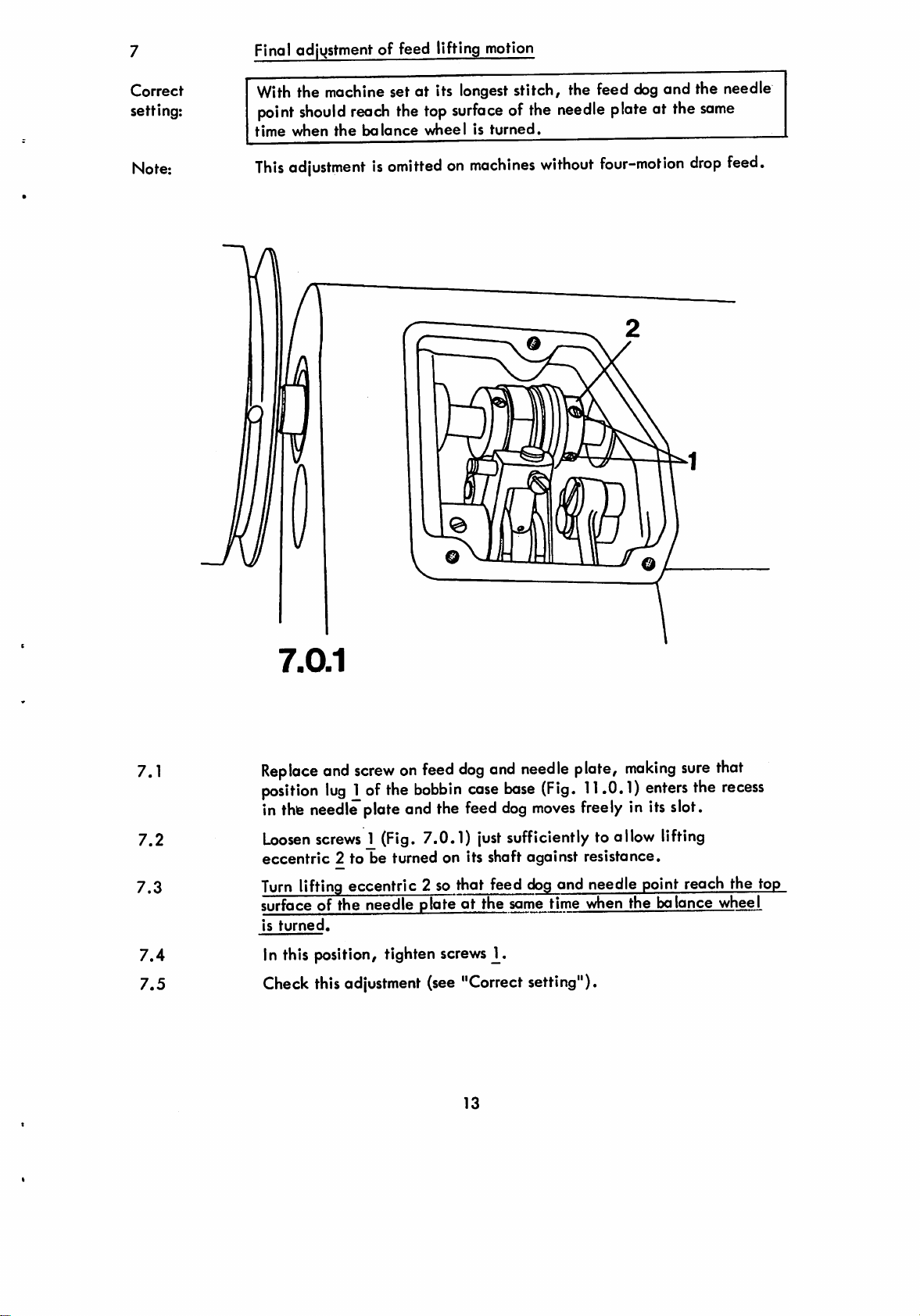
Final adjvjstment of feed lifting motion
Correct
setting:
Note:
With
the machine set at its
point
should
time when
This
adjustmentisomittedonmachines
the
reach
balance
the
longest
top
surfaceofthe
wheelisturned.
stitch, the feed
needle
without
plate
four-motion
dog
and the needle
at the
drop
same
feed.
7.1
7.2
7.3
7.4
7.5
7.0.1
Replace
position
in
Loosen
eccentric
Turn
surface of
is
In this position, tighten screws2•
Check this
and
screwonfeed
lug
1of
the
thiB
needle
screws
lifting eccentric 2 so that feed
turned.
plateand the
1 (Fig. 7.0.1)
2 to be turned on its shaft against resistance.
the
needle
adjustment
dog
bobbin
feed
plateatthe
(see "Correctsetting").
13
and
case
just
needle
base
dog
(Fig.
moves
plate,
11.0.1)
freely
making
enters
in its slot.
sufficiently to allow lifting
dog
and needle point reach the top
same time when the
balance
sure
the
that
recess
wheel
Page 14

Correct
setting;
Note:
Cleoronce
(On
subcl.
When
on
subcl.
it and the needle plate.
The
clearanceonsubcl.
determinedbythe
between
"706/35;
the
presser
-706/35orabout14mmonsubcl.-706/47
presser
footisraised,
machine
0
D
foot
-706/47
-706/05,
design.
and
end
there
needle
-706/48
shouldbea
-706/07
plate
machines
and
only)
clearanceofabout11mm
and
-706/48
-706/25
machines
between
is
8.1
8.2
8.3
8.4
8.5
8.6
Note:
Operate
Reduce
Loosen
Adjust
or
14.0
In
this
to
the
Check
Regulate
a
sewing
the
the
screws
the
mm
|:»sition,
edgeofthe
this
the
test.
presser
bar
pressureonthe
2of
lifting
presser
bar
vertically
respectively
tighten
needle
adjustment
presser
(see
foot
8.0.2
liftertoraise
presser
collar
between
screws2,making
plater ^orisser
"Correct
pressurebyturninginscrew1while
the
presser
barbyturning
3.
untfl
thereisa
presser
foot
sure
setting").
14
foot.
out
screw
1.
clearanceofabout11mm
and
needle
the
plate.
presser
footisset
making
— ®
parallel
parallel
Page 15

Top-to-boftom-feed timing
Correct
setting:
With
stud1centeredinits
needle
and
the
plote,
other
the
half
vibroting
below
the
slot
and
presser
presser
the
should
foot
presser
moke
sole.
foot
half
lowered
its
motion
onto
above
the
9.1
9.2
9.3
9.4
n
9.0.2
Make
sure
the
presser
1 is centered in its slot, then
allow
lever 3 to be
Adjust
above and the other half
balance
In this position, tighten both
Check this
lever3so
wheelisturned.
adjustment
footislowered
turned
that the
vibrating
below
'
(see "Correct setting").
ontothe
loosen
on drive shaft 4
screws 2 just sufficiently to
presser
the
presser
screws
2.
needle
against
makes
foot sole
half its
plate and
resistance.
motion
when
the
stud
15
Page 16

10
Top feed lifting motion
Correct
setting;
With
and
the
the
presser
needle
foot
point
should
restingonthe
reach
needle
the
needle
plate,tevibrating
plateatthe
same
presser
time.
10.1
10.2
10.3
10.4
10.5
10.0.2
Operate
Loosen
on Its shaft
Turn
lifting
reach
the
In
this
position,
Check
this
presser
bar
screws2|ust
against
eccentric3until
needle
plateatthe
tighten
adjustment
lifter^to
lower
the
sufficientlytoallow
resistance.
the
vibrating
same
time
screws
(see
2.
"Correct
16
setting").
presser
lifting
presser
when
the
foot
onto
the
needle
plate,
eccentric3tobeturned
~
and
the
balance
needle
wheelisturned.
point
Page 17

11
Bobbin cose
(On
two-needle
opener
machines,
moke
this
adjustment
twice.)
Correct
setting;
The
and
of
the
needle
bobbin
thread
cose
recessinthe
mustbetrapped
base5nor
needle
between
plate
neither
position
(see
arrowsinFig.
between
lug
and
opener
the
11.0.2).
finger
walls
11.0.2
4
11.1
11.2
11.3
11.4
11.5
Thread
and
Loosen
against
Turn
vMeel
finger4and
wallsofthe
from
up through the needle holeT
In this position, tighten
Check
the
machine,
lower
the
screws2just
resistance.
collar3on
the
needle
bobbin
recessinthe
the
time
the
this
adjustment
placeapieceoffabric
latter.
sufficientlytoallow
the
hook
thread
loopispickedupby
willbetrapped
cose
base5nor
screws
(see
bracketsothat
between
needle
plate
the
2.
"Correct
17
setting").
under
collar
when
neither
position
(see
arrowsinFig.
hook
the
3 to be
you
turn
between
lug1and
point
untilitis
presser
turned
the
balance
opener
11.0.2)
foot
the
pulled
Page 18

12
Correct
setting:
Note:'
Tension
(On
When
0.5
The
a clearance of more than
release
two-needle
the
presser
mm
apart.
clearance of
mechanism
machines,
footisraised,
0.5
mm
moke
is the
1.0
this
adjustment
both
tension
minimum
mm
may be required.
twice).
discs
shouldbeat
clearance; for thicker threads
least
12.1
12.2
12.3
j
iJT
12.0.1
Operate the presser bar lifter to raise the presser foot.
Adjust
ofatleast
With effective tension pin 3 must,not be under stress.
Check this adjustment (see "Correct setting").
thrust plate 1 behind tension base plate 2 so that there is oclearance
0.5
mm
between
both
tension
discs.
12.0.2
18
Page 19

13
Threod check spring
Correct
setting:
Note:
The
strokeofthe
needle
thickness
Special
spring for a shorter or longer stroke.
point
(which
sewing
thread
has
reached
equalsastroke
operations
check
the
may
spring
surface
of obt. 7
makeitnecessary
shouldbecompleted
ofa pieceof
mm).
fabricofmedium
to setthe
O
when
check
the
13.1
13.2
13.3
13.4
13.5
Make
sure
the
fabric
Loosen
Turn
lever
Continue
thread
stroke.
In
tighten screw 1.
the
to its
this
under
the
screw
balance
highest
turning
check
spring
position,
©
machine
presser
1.
has
foot
been
wheeltosewafew
point.
the
balance
has
recededtothe
push
stop2up
threaded,
and
lower
stitches,
wheelinits
against
then
the latter.
then
normal
starting
the
thread
placeapiece
bring
direction
the
until
of
take-up
the
positionofits7mm
check
spring
and
13.6
Check
this
adjustment
(see
19
"Correct
setting").
Page 20

14
Correct
setting:
Bobbin
When
reliably;
wheel 3
winder
the
must
bobbin
when
outomoTically
about
1.0
mm
winderisengaged
the
bobbin
winderisdisengaged,
the
winder
spindle
however,
shouldbedriven
friction
not contact drive wheel 2. The bobbin winder should stop
when
the
below
its
thread
rim.
woundonthe
bobbin
has
reachedapoint
14.1
14.2
14.3
14.4
14.5
14.6
14.7
14.0.1
Engage the bobbin winder.
Loosen
Adjust the position of the arm shaft to set drWe wheel 2 so close to
friction wheel 3 that the latter will be driven reliably when the
balance
winderisdisengaged.
In this position, tighten
Loosen
If the bobbin is too full, push stud 5 toward the
enough, push the stud toward
Check this adjustment (see "Correct setting").
screws
wheel is
screws
J_,
4.
turned,
but
both
will
not be driven when
screws
the
20
left
J_.
and
right,
tighten screw
the
bobbin
if it is not full
4.
14.0.2
Page 21

15 Final worksteps
15.1 Replace and screw on the face
15.2
15.3 Make a sewing test and
Replace
both of them)below bedplate.
bar pressure by turning screw 1 in or out (Fig.
proper feeding is ensured evenattop speed.
and
screw on bevel gear housing (on 2-needle machines
at
the same time regulate the presser
and
all
other covers.
8.0.1)
until
21
Page 22

PFAFF
Innovation
Pfaff,
D-6750
Kaisersbutern,
Postfach
Telefax
mode
3020/3040,Telefon (0631) 200<D,
(0631)17202
by
PFAFF
Telex45753
 Loading...