

Page 1

1245
1246
Instruction manual
This instruction manual applies to machines from the
following serial numbers onwards:
PFAFF 1245 # 527 678
PFAFF 1246 # 527 679
296-12-18 401/002
Betriebsanleitung engl. 01.02
Page 2

This Instruction manual is valid for all models and subclasses listed in the
chapter „Specifications“.
The reprinting, copying or translation of PFAFF Instruction Manuals, whether in whole or in
part, is only permitted with our previous permission and with written reference to the
source.
PFAFF Industrie Maschinen GmbH
Postfach 3020
D-67653 Kaiserslautern
Königstr. 154
D-67655 Kaiserslautern
Editing/Illustrations
Verlag - TD
D - 77901 Lahr
Page 3

Index
Contents ............................................................................... Chapter - Page
1 Safety ..........................................................................................................................1 - 1
1.01 Directives ..................................................................................................................... 1 - 1
1.02 General notes on safety ............................................................................................... 1 - 1
1.03 Safety symbols ............................................................................................................ 1 - 2
1.04 Important points for the user ....................................................................................... 1 - 2
1.05 Operating and specialist personnel .............................................................................. 1 - 3
1.05.01 Operating personnel .................................................................................................... 1 - 3
1.05.02 Specialist personnel ..................................................................................................... 1 - 3
1.06 Danger ......................................................................................................................... 1 - 4
2 Proper use .................................................................................................................. 2 - 1
3 Specifications ............................................................................................................. 3 - 1
3.01 PFAFF 1245 ................................................................................................................. 3 - 1
3.02 Possible models and subclasses ................................................................................. 3 - 1
-1
3.03 Max. number of stitches/min
3.04 PFAFF 1246 ................................................................................................................. 3 - 3
3.05 Possible models and subclasses ................................................................................. 3 - 3
3.06 Max. number of stitches/min
......................................................................................................................................................
-1
......................................................................................................................................................
3 - 2
3 - 4
4 Disposal of the machine ........................................................................................... 4 - 1
5 Transport, packaging and storage ........................................................................... 5 - 1
5.01 Transport to the customer ........................................................................................... 5 - 1
5.02 Transport within the customer’s premises .................................................................. 5 - 1
5.03 Disposal of the packaging ............................................................................................ 5 - 1
5.04 Storage ........................................................................................................................ 5 - 1
6 Explanation of the symbols ...................................................................................... 6 - 1
7 Controls ...................................................................................................................... 7 - 1
7.01 On/off switch ............................................................................................................... 7 - 1
7.02 Pedals (on machines with subclass -910/01) ............................................................... 7 - 1
7.03 Pedal (on machines with automatic presser-foot lifter (subclass -910/98) ................... 7 - 1
7.04 Key on the machine head (for machines with backtacking mechanism -911/97) ......... 7 - 2
7.05 Lever for lifting the presser foot .................................................................................. 7 - 2
7.06 Feed regulator / reverse sewing .................................................................................. 7 - 3
7.07 Feed regulator on machines with backtacking mechanism -911/97 ............................ 7 - 3
7.08 Adjustment nut for the top-feed stroke ....................................................................... 7 - 4
Page 4

Index
Contents ............................................................................... Chapter - Page
8 Mounting and commissioning the machine ........................................................... 8 - 1
8.01 Mounting .....................................................................................................................8 - 1
8.01.01 Adjusting the table-top height ...................................................................................... 8 - 1
8.01.02 Adjusting the V-belt tension ......................................................................................... 8 - 2
8.01.03 Mounting the upper V-belt guard ................................................................................. 8 - 2
8.01.04 Mounting the lower V-belt guard ................................................................................. 8 - 3
8.01.05 Mounting tilt-over safeguard ........................................................................................ 8 - 3
8.01.06 Mounting the spool holder ............................................................................................. 8 - 4
8.01.07 Mounting the sewing lamp ........................................................................................... 8 - 4
8.02 Table top cutout ............................................................................................................ 8 - 5
8.02.01 PFAFF 1245 .................................................................................................................. 8 - 5
8.02.02 PFAFF 1246 .................................................................................................................. 8 - 6
8.03 Commissioning the machine ........................................................................................ 8 - 7
8.04 Switching the machine on/off ....................................................................................... 8 - 7
9 Preparation .................................................................................................................. 9 - 1
9.01 Inserting the needle in the PFAFF 1245 ......................................................................... 9 - 1
9.02 Inserting the needle in the PFAFF 1246 ......................................................................... 9 - 2
9.03 Winding the bobbin thread, adjusting the thread tension ............................................... 9 - 2
9.04 Removing/Threading the bobbin case ........................................................................... 9 - 3
9.05 Inserting the bobbin case / Adjusting the bobbin thread tension .................................... 9 - 3
9.06 Threading the needle thread /
Adjusting the needle thread tension in the PFAFF 1245 ................................................. 9 - 5
9.07 Threading the needle thread /
Adjusting the needle thread tension in the PFAFF 1246 .............................................. 9 - 6
10 Care and maintenance ............................................................................................ 10 - 1
10.01 Servicing and maintenance intervals .......................................................................... 10 - 1
10.02 Cleaning ..................................................................................................................... 10 - 1
10.03 General lubrication ...................................................................................................... 10 - 2
10.04 Lubricating the hook ................................................................................................... 10 - 3
10.05 Lubricating the head ................................................................................................... 10 - 4
10.06 Lubricating the top-feed drive excentric ...................................................................... 10 - 4
10.07 Checking the air pressure ........................................................................................... 10 - 5
10.08 Emptying / Cleaning the water container of the air filter .............................................. 10 - 5
11 Adjustment ............................................................................................................... 11 - 1
11.01 Tools, gauges and other accessories for adjusting .................................................... 11 - 1
11.02 Notes on adjusting ..................................................................................................... 11 - 1
Page 5

Index
Contents ............................................................................... Chapter - Page
11.03 Abbreviations .............................................................................................................. 11 - 1
11.04 Adjusting the basic machine ................................................................................... 11 - 2
11.04.01 Positioning the feed dog across the direction of sewing .............................................. 11 - 2
11.04.02 Positioning the feed dog in the direction of sewing ..................................................... 11 - 3
11.04.03 Height of the bottom feed-dog .................................................................................... 11 - 4
11.04.04 Pre-adjusting the needle height ................................................................................... 11 - 5
11.04.05 Centering the needle in the needle hole ...................................................................... 11 - 6
11.04.06 Lifting motion of the bottom feed-dog ......................................................................... 11 - 7
11.04.07 Driving motion of the bottom and top feeds ................................................................ 11 - 8
11.04.08 Hook-to-needle clearance, needle rise, needle height and needle guard ...................... 11 - 9
11.04.09 Top-feed stroke ............................................................................................................ 11-11
11.04.10 Lifting motion of the top feed ....................................................................................... 11-12
11.04.11 Bobbin-case opener ..................................................................................................... 11-13
11.04.12 Safety clutch ............................................................................................................... 11-14
11.04.13 Needle thread tension release ...................................................................................... 11-15
11.04.14 Thread check spring .................................................................................................... 11-16
11.04.15 Thread check spring on PFAFF 1246 with thread trimmer -900/56 ............................... 11-17
11.04.16 Bobbin winder ............................................................................................................. 11-18
11.04.17 Presser-foot pressure .................................................................................................. 11-19
11.05 Adjusting the thread trimmer -900/56 ........................................................................ 11-20
11.05.01 Pre-adjusting the control cam ...................................................................................... 11-20
11.05.02 Tripping lever ............................................................................................................... 11-21
11.05.03 Pawl ............................................................................................................................ 11-22
11.05.04 Engaging solenoid ........................................................................................................ 11-23
11.05.05 Release trip ................................................................................................................. 11-24
11.05.06 Engaging lever ............................................................................................................. 11-25
11.05.07 Linkage rod .................................................................................................................. 11-26
11.05.08 Final adjustment of the control cam ............................................................................. 11-27
11.05.09 Catch ........................................................................................................................... 11-28
11.05.10 Connecting rod (for PFAFF 1246 only) .......................................................................... 11-29
11.05.11 Thread-catcher height .................................................................................................. 11-30
11.05.12 Knife ............................................................................................................................ 11-31
11.05.13 Thread catcher reverse position ................................................................................... 11-32
11.05.14 Bobbin-thread clamp spring ......................................................................................... 11-34
11.05.15 Tension release bar ..................................................................................................... 11-36
11.05.16 Positioner .................................................................................................................... 11-38
12 Wearing parts ........................................................................................................... 12 - 1
Page 6

Safety
1 Safety
1.01 Directives
1.02 General notes on safety
This machine is constructed in accordance with the European regulations contained in the
conformity and manufacturer’s declarations.
In addition to this Instruction Manual, observe also all generally accepted, statutory and
other regulations and legal requirements -including those of the country and all valid environmental protection regulations!
The regionally valid regulations of the social insurance society for occupational accidents or
other supervisory organisations are to be strictly adhered to!
● This machine may only be operated by adequately trained operators and only after
having completely read and understood the Instruction Manual!
● All Notes on Safety and Instruction Manuals of the motor manufacturer are to be read
before operating the machine!
● The danger and safety instructions on the machine itself are to be followed!
● This machine may only be used for the purpose for which it is intended and may not be
operated without its safety devices. All safety regulations relevant to its operation are to
be adhered to.
● When exchanging sewing tools (e.g. needle, presser foot, needle plate, feed dog or
bobbin), when threading the machine, when leaving the machine unattended and during
maintenance work, the machine is to be separated from the power supply by switching
off the On/Off switch or by removing the plug from the mains!
● Everyday maintenance work is only to be carried out by appropriately trained personnel!
● Repairs and special maintenance work may only be carried out by qualified service staff
or appropriately trained personnel!
● When servicing or carrying out repairs on pneumatic devices, the machine is to be
removed from the compressed air supply! The only exceptions to this are adjustments
and function checks carried out by appropriately trained personnel!
● Work on electrical equipment may only be carried out by appropriately trained personnel!
1 - 1
● Work is not permitted on parts and equipment which are connected to the power
supply! Exceptions to this are only to be found in the regulations EN 50110.
● Modifications and alterations to the machine may only be carried out under observance
of all the relevant safety regulations!
● Only spare parts which have been approved by us are to be used for repairs! We
expressly point out that any replacement parts or accessories which are not supplied by
us have not been tested and approved by us. The installation and/or use of any such
products can lead to negative changes in the structural characteristics of the machine.
We shall not be liable for any damage which may be caused by non-original parts.
Page 7
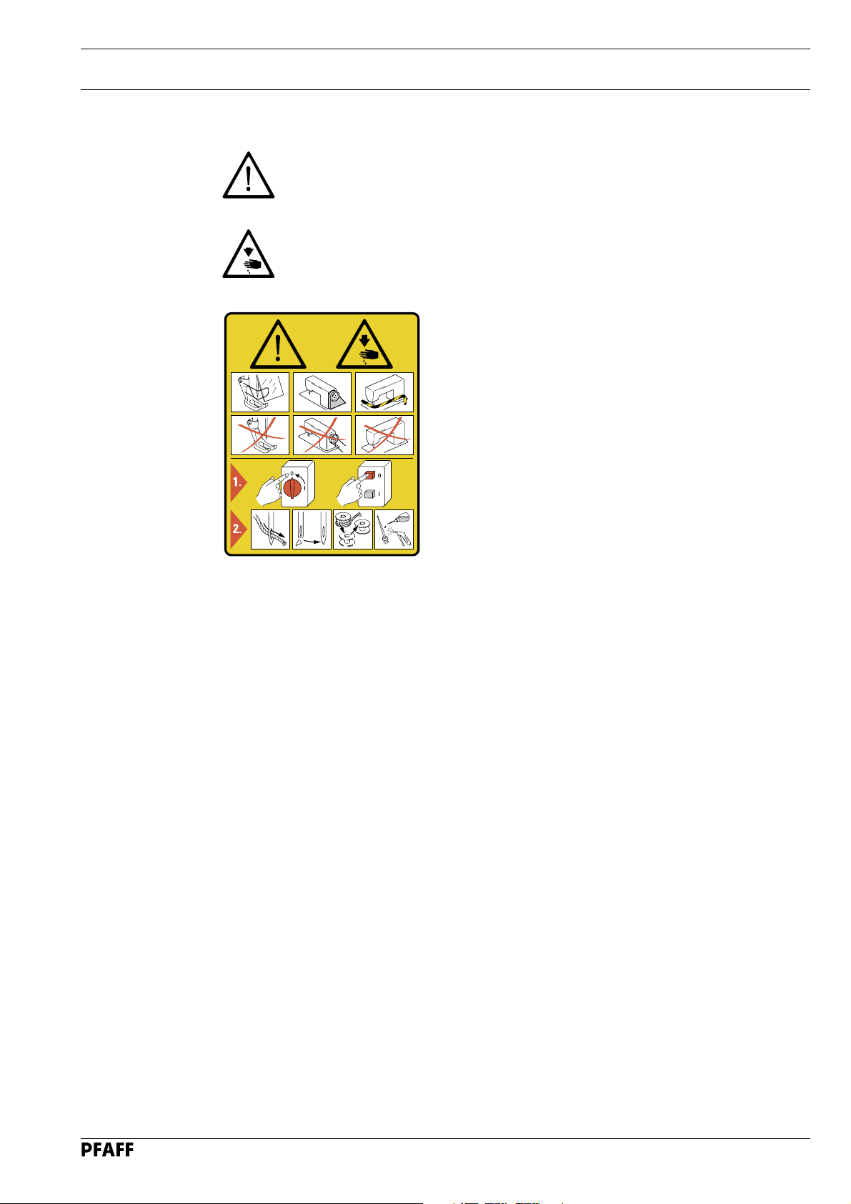
1.03 Safety symbols
Danger!
Points to be observed.
Danger of injury for operating and specialist personnel!
Safety
Caution
Do not operate without finger guard and safety devices.
Before threading, changing bobbin and needle, cleaning
etc. switch off main switch.
I
1.04 Important points for the user
● This Instruction Manual is a component part of the machine and must be available to the
operating personnel at all times.
● The Instruction Manual must be read before operating the machine for the first time.
● The operating and specialist personnel is to be instructed as to the safety equipment of
the machine and regarding safe work methods.
● It is the duty of the operator to only operate the machine in perfect running order.
● It is the obligation of the operator to ensure that none of the safety mechanisms are
removed or deactivated.
● It is the obligation of the operator to ensure that only authorized persons operate and
work on the machine.
Further information can be obtained at your PFAFF agent.
1 - 2
Page 8

Safety
1.05 Operating and specialist personnel
1.05.01 Operating personnel
Operating personnel are persons responsible for the equipping, operating and cleaning of
the machine as well as taking care of faults arising in the sewing area.
The operating personnel is obliged to observe the following points and must:
● always observe the Notes on Safety in the Instruction Manual!
● never use any working methods which could limit the level of safety in using the
machine!
● not wear loose-fitting clothing or jewellery such as chains or rings!
● also ensure that only authorized persons operate the machine.
● always immediately report to the user any changes in the machine which may limit its
safety!
1.05.02 Specialist personnel
Specialist personnel are persons with a specialist education in the fields of electrics,
electronics and mechanics. They are responsible for the lubrication, maintenance, repair and
adjustment of the machine.
The specialist personnel is obliged to observe the following points and must:
● always observe the Notes on Safety in the Instruction Manual!
● switch off the On/Off switch before carrying out adjustments or repairs and ensure that
it cannot be switched on again unintentionally!
● never work on parts which are still connected to the power supply! Exceptions are
contained only in the regulations EN 50110.
● when servicing or carrying out repairs on pneumatic devices, remove the machine from
the compressed air supply! The only exceptions to this are function checks.
● replace the protective coverings and close the electrical control box after all repairs or
maintenance work!
1 - 3
Page 9
1.06 Danger
A working area of 1 metre is to be kept free both in front of and behind the
machine while it is in operation so that it is always easily accessible.
Never reach into the sewing area while sewing! Danger of injury by the needle!
Never leave objects on the table or in the needle plate area while adjusting the
machine settings! Objects can become trapped or be slung away! Danger of
injury!
On mechanically activated clutch motors without an actuating lock, wait until
the motor has come to a standstill! Danger of injury!
Safety
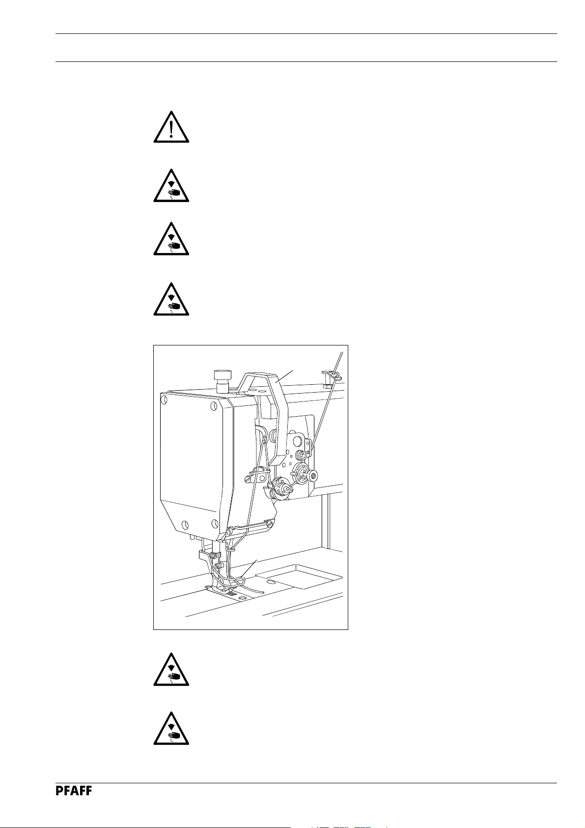
Fig. 1 - 01
1
2
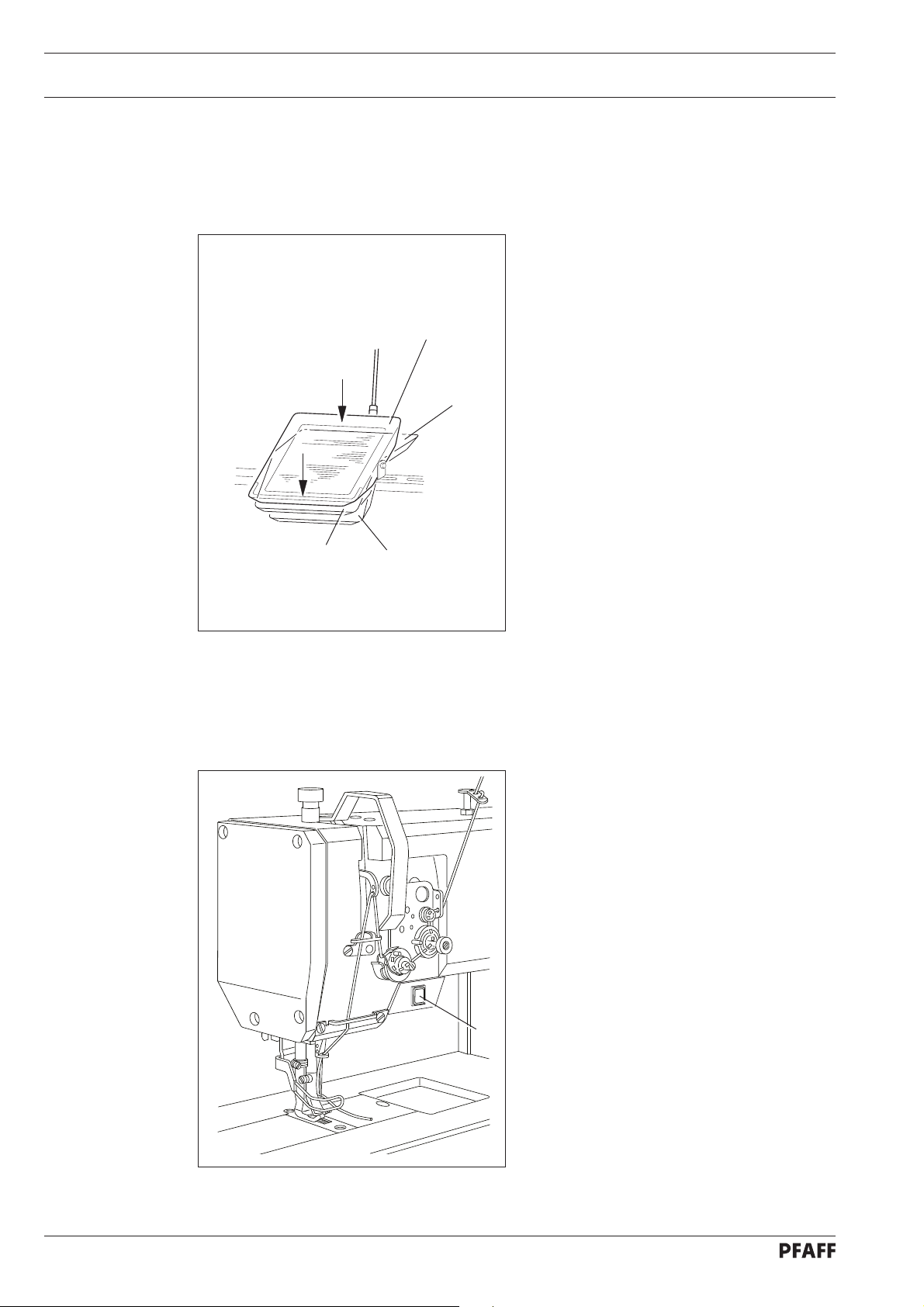
Do not operate the machine without the take-up lever guard 1!
Danger of injury due to the movement of the take-up lever!
Do not operate the machine without the finger guard 2!
Danger of injury by the moving needle!
1 - 4
Page 10
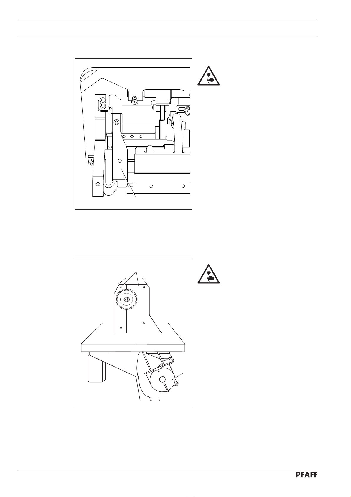
Safety
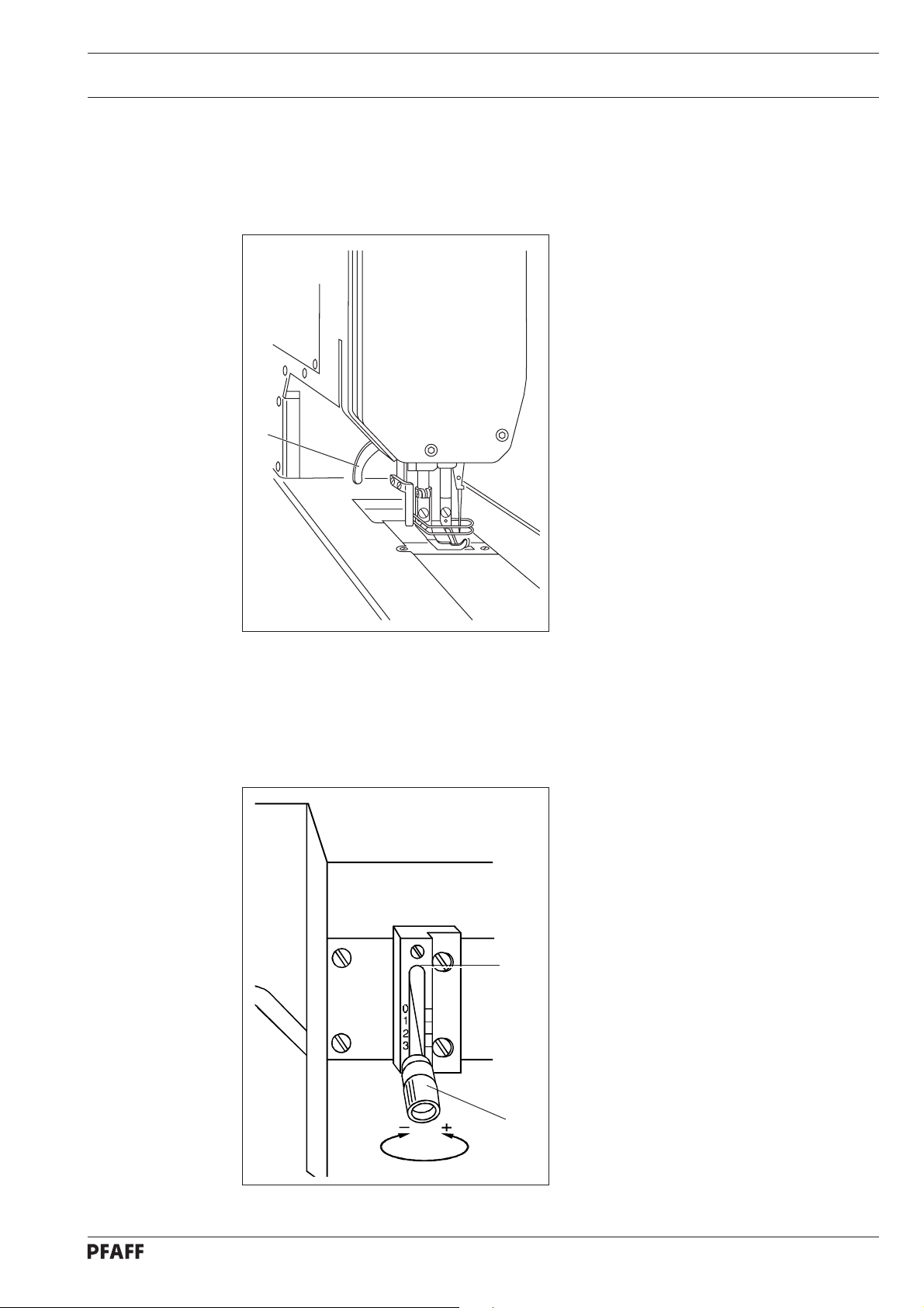
Do not operate the machine
without tilt-back safeguard 3!
Danger of crushing between
upper part and table top!
Fig.1 - 02
3
4
Do not operate the machine
without belt guards 4 and 5!
Danger of injury by the revolving
V-belt!
5
1 - 5
Fig. 1 - 03
Page 11

2 Proper use
PFAFF 1245
The PFAFF 1245 is a single needle, flatbed sewing machine with bottom, top and needle
feeds as well as a large vertical hook for sewing lockstitch seams. The machine is designed
for commercial use (industry).
PFAFF 1246
The Pfaff 1246 is a two-needle, flat bed sewing machine with bottom, top and needle feed
as well as vertical sewing hook for lockstitch seams. The machine is intended for commercial
(industrial) use only.
Proper use
Any and all uses of this machine which have not been approved of by the
manufacturer are considered to be inappropriate! The manufacturer cannot be
held liable for any damage caused by the inappropriate use of the machine!
The appropriate use of the machine includes the observance of all operational,
adjustment, maintenance and repair measures required by the manufacturer!
2 - 1
Page 12

Specifications
3 Specifications
3.01 PFAFF 1245
Stitch type:........................................................................................................ 301 (lockstitch)
Needle system:..............................................................................................................134-35
Needle thickness in 1/100 mm:
Model C: .....................................................................................................................110 - 140
Max. thread thickness (synthetic ▲ ):
Model C: ........................................................................................................................... 20/3
Max. stitch length:
Model N: ...................................................................................................................... 6.0 mm
Model N8: .................................................................................................................... 8.0 mm
Handwheel eff. dia.: ...................................................................................................... 80 mm
Max. speed: ................................................................................................... see chapter 3.03
Dimensions of machine:
Length:........................................................................................................... approx. 570 mm
Width: .............................................................................................................approx. 177 mm
Height: ............................................................................................................approx. 410 mm
◆
Clearance width: ......................................................................................................... 265 mm
Clearance height: .........................................................................................................115 mm
Fabric clearance (presser foot raised): .......................................................................... 14 mm
Net weight (machine head): ................................................................................ approx. 40 kg
Power supply:.......................................................................... 190 - 240 V 50 / 60 Hz, 1 phase
Power consumption: .............................................................................................max. 600 VA
Fuse protection:.................................................................................. 1 x 16 A, delayed action
Working air pressure:....................................................................................................... 6 bar
Air consumption:......................................................................................... ~0.8 l / work cycle
Working noise level:
Emission at workplace
n = 2300 spm: ...........................................................................................................82 dB (A)
Noise measurement in accordance with DIN 45 635-48-A-1
◆
Subject to alteration
▲
Or comparable thicknesses of other thread types
3.02 Possible models and subclasses
Model C: ................................................................... For processing medium-heavy materials
Additional equipment:
Subclass -900/56..............................................................................................Thread trimmer
Subclass -910/ ...............................................................................Automatic presser- foot lifter
Subclass -911/ ............................................................................................................Bartacker
3 - 1
Page 13

Specifications
3.03 Max. number of stitches/min
Top feed lift Max. number of
stitch lengths up to 6 mm
less than 3.5 mm
from 3.5 to 5.5 mm
from 5.5 to 7 mm
-1
Max. number of
stitches/min
2800
2500
2000
-1
for
stitches/min-1 for stitch
lengths from 6 mm to 8 mm
2600
2500
2000
3 - 2
Page 14

Specifications
3.04 PFAFF 1246
Stitch type:........................................................................................................ 301 (lockstitch)
Needle system:..............................................................................................................134-35
Needle thickness in 1/100 mm:
Model B: ......................................................................................................................80 - 100
Model C: .....................................................................................................................110 - 140
Max. thread thickness (synthetic ▲ ):
Model B: ........................................................................................................................... 40/3
Model C: ........................................................................................................................... 20/3
Max. stitch length:
Model BN and CN: ....................................................................................................... 6.0 mm
Model CN8:.................................................................................................................. 8.0 mm
Handwheel eff. dia.: ...................................................................................................... 80 mm
Max. speed: ................................................................................................... see chapter 3.06
Dimensions of machine:
Length:........................................................................................................... approx. 570 mm
Width: .............................................................................................................approx. 177 mm
Height: ............................................................................................................approx. 410 mm
◆
Clearance width: ......................................................................................................... 265 mm
Clearance height: .........................................................................................................115 mm
Fabric clearance (presser foot raised): .......................................................................... 14 mm
Net weight (machine head): ................................................................................ approx. 40 kg
Power supply:.......................................................................... 190 - 240 V 50 / 60 Hz, 1 phase
Power consumption: .............................................................................................max. 600 VA
Fuse protection:.................................................................................. 1 x 16 A, delayed action
Working air pressure:....................................................................................................... 6 bar
Air consumption:......................................................................................... ~0.8 l / work cycle
Working noise level:
Emission at workplace
n = 2200 spm: ...........................................................................................................82 dB (A)
Noise measurement in accordance with DIN 45 635-48-A-1
◆
Subject to alteration
▲
Or comparable thicknesses of other thread types
3.05 Possible models and subclasses
3 - 3
Model B: ..............................................................................For processing medium materials
Model C: ................................................................... For processing medium-heavy materials
Additional equipment:
Subclass -900/56..............................................................................................Thread trimmer
Subclass -910/04 ...........................................................................Automatic presser-foot lifter
Subclass -911/35 ........................................................................................................Bartacker
Page 15

Specifications
3.06 Max. number of stitches/min
for
-1
Top feed lift
less than 3.5 mm
from 3.5 to 5.5 mm
from 5.5 to 7 mm
Max. number of stitches/min
stitch lengths up to 6 mm and
2700 2500
2400 2200
1900 1700
-1
needle gauge of up to 10 mm
for
-1
Max. number of stitches/min
stitch lengths up to 6 mm and
needle gauge of more than 10 mm
for
-1
Max. number of stitches/min
2500 230 0
2400 2100
1900 1600
for
-1
stitch lengths from 6 mm to 8 mm
and needle gauge of up to 10 mm
Max. number of stitches/min
stitch lengths up to 6 mm to 8 mm
and needle gauge of more than
10 mm
3 - 4
Page 16

Disposal of the machine
4 Disposal of machine waste
● The proper disposal of machine waste is the responsibility of the customer.
● The materials used on the machines are steel, aluminium, brass and various plastics.
The electrical equipment consists of plastics and copper.
● The machine waste is to be disposed of in accordance with the locally valid
environmental protection regulations. If necessary a specialist is to be commissioned.
Special care is to be taken that parts soiled with lubricants are separately
disposed of in accordance with the locally valid pollution control regulations!
4 - 1
Page 17

Transport pack aging and storage
5 Transport packaging and storage
5.01 Transport to the customer’s premises
Within the Federal Republic of Germany, the machine is delivered without packaging.
Machines for export are packaged in a crate or wrapped depending on how they are
transported.
5.02 Transport within the customer’s premises
The manufacturer carries no liability for transport within the customer’s premises. Care is
to be taken to transport the machine in an upright position only.
5.03 Disposal of the packaging
The packaging of the machine consists of wood, paper, cardboard and VCE fibre. The proper
disposal of the packaging is the responsibility of the customer.
5.04 Storage
The machine can be stored for up to 6 months if not in use. During this time it should be
protected from dust and moisture.
For longer storage the individual parts of the machine, especially the moving parts, should
be protected against corrosion e.g. by a film of oil.
5 - 1
5 - 1
Page 18

Explanation of the symbols
6 Explanation of the symbols
In the following section of this Instruction Manual, certain tasks or important pieces of
information are accentuated by symbols.
The symbols used have the following meanings:
Note, information
Cleaning, care
Lubrication, greasing
Servicing, repairing, adjustment, maintenance
(only to be carried out by specialist personnel)
6 - 1
Page 19
7 Controls
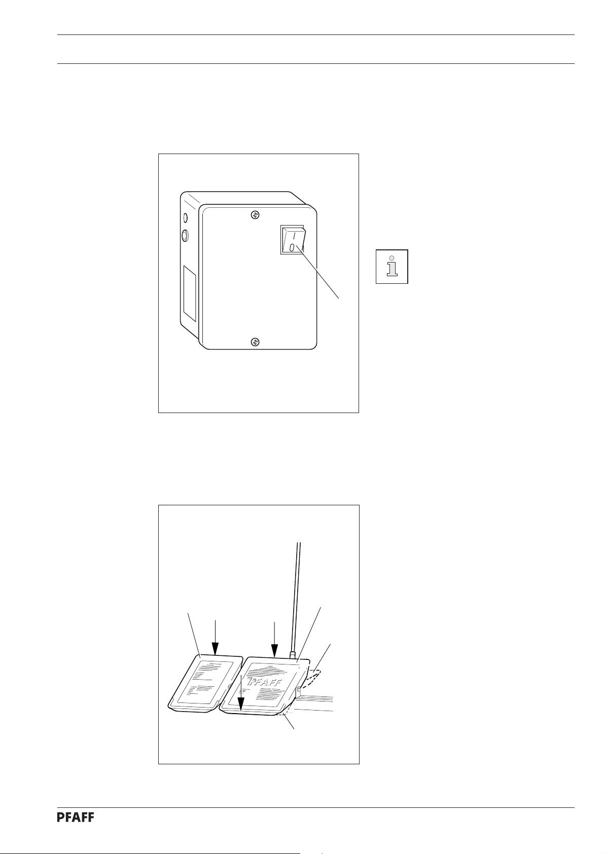
7.01 On/off switch
Controls
● Turn the machine on and off by switching
the on/of f switch 1 on and off. When the
machine is on, the light in the switch is
also on.
The switch in the illustration can
be found on machines with Quick
motors. When other motors are
used, the switch may not look
the same.
1
Fig. 7 - 01
7.02 Pedals (on machines with subclas -910/01)
+ 2
0
+ 1
With the on/off switch on
0 = Machine stop
+1 = Sew
- 1 = Trim thread (on machines with thread
trimmer)
+2 = Raise presserfoot
Fig. 7 - 02
- 1
7 - 1
Page 20
Controls
7.03 Pedal (on machines with automatic presser-foot lifter -910/98)
With the on/off switch on
0 = Machine stop
+1 = Sew
Fig. 7 - 03
- 1
0
+ 1
- 2
- 1 = Raise presserfoot
- 2 = Trim thread (on machines with thread
trimmer)
7.04 Key on the machine head (for machines with backtacking mechanism -911/97)
Fig. 7 - 04
● Switch to reverse sewing by pressing
key 1 while sewing.
1
7 - 2
Page 21
7.05 Lever for lifting the presser foot
1
Controls
● The sewing foot can be lifted by raising
lever 1.
Fig. 7 - 05
7.06 Feed regulator / reverse sewing
R
● Adjust the stitch length by turning the
knurled nut 1 accordingly.
Reverse sewing
● Press knurled nut 1 upwards as far as
possible (position „R“).
Fig. 7 - 06
1
7 - 3
Page 22
Controls
7.07 Feed regulator (on machines with backtacking mechanism -911/97)
You can set the length of the reverse stitch
2
1
as large as is required, independent of the
forward stitch.
● The forward stitch is set with knurled
screw 1 and the re v erse stitch with
knurled screw 2.
The options for setting the
automatic start and end bartacks
are to be found in the instruction
manual of the motor.
Fig. 7 - 07
7.08 Adjustment nut for the top-feed stroke
1
2
Turn the machine off!
● Open cover 1 on the back of the
mac hine, loosen screw 2 and move as
required.
7 - 4
Fig. 7 - 08
Page 23
Mounting and commissioning the machine
8 Mounting and commissioning the machine
The machine must only be mounted and commissioned by qualified personnel!
All relevant safety regulations are to be observed!
If the machine is delivered without a table, it must be ensured that the frame
and the table top which you intend to use can hold the weight of the machine
and the motor, even while sewing.
8.01 Mounting
The necessary electricity and compressed air supplies must be available at the machine’s
location (see specifications).
A stable and horizontal surface as well as sufficient illumination at the machine’s location.
Due to reasons of packaging, the table top is lowered for transport. The
following is a description of how to adjust the height of the table top.
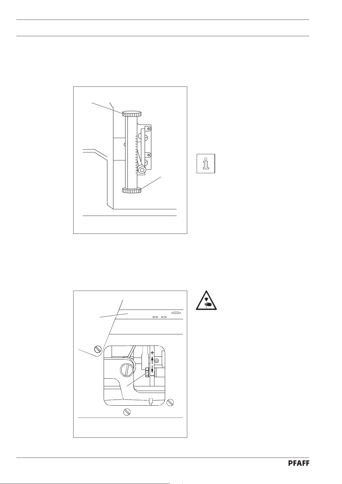
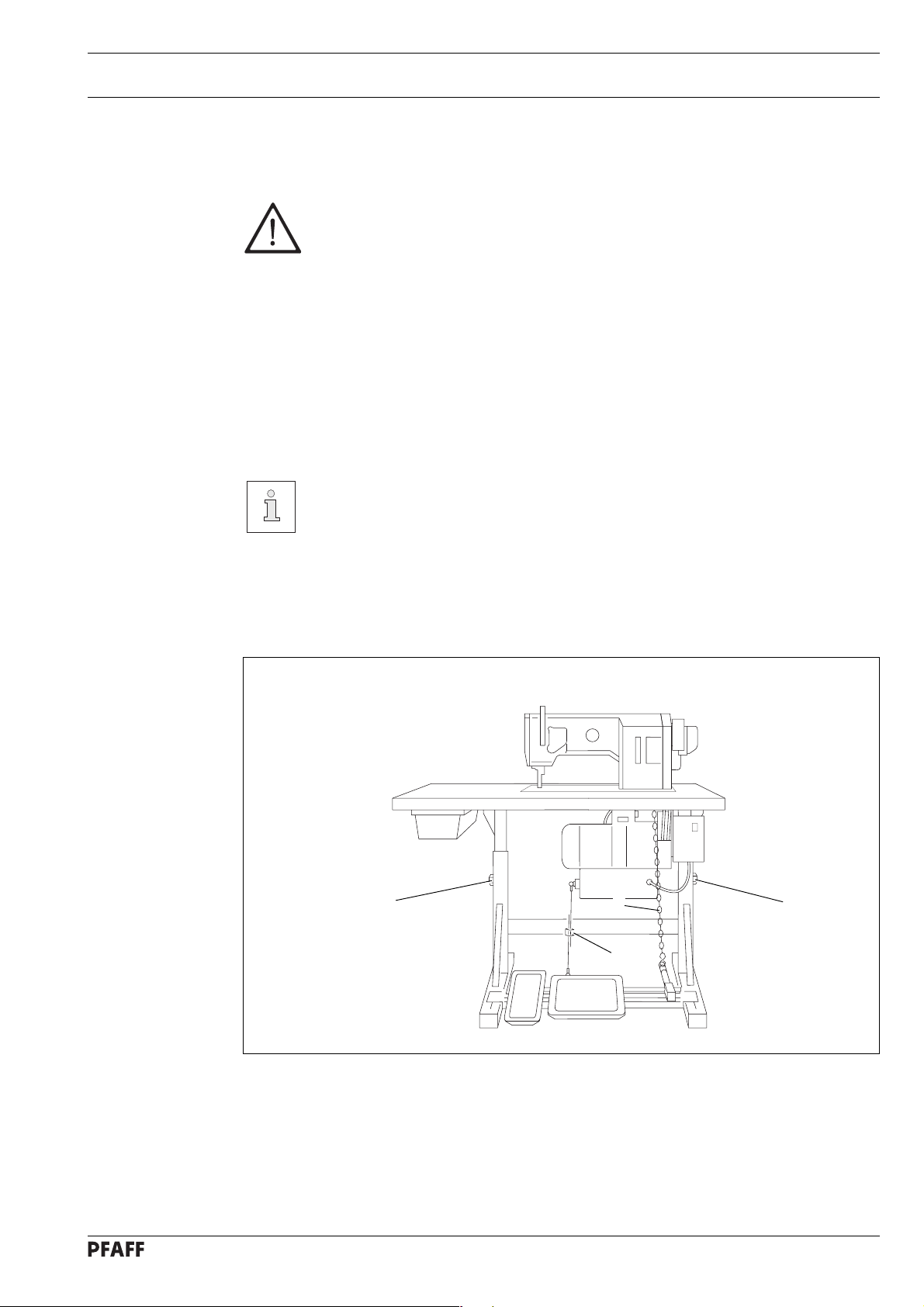
8.01.01 Adjusting the table-top height
1
Fig. 8 - 01
3
1
2
● Loosen screws 1 and 2.
● Set the desired table-top height and tighten screws 1 well.
● Adjust the position of the right pedal so that you can operate it comfortably and tighten
screw 2.
● The setting of the left pedal can be adjusted with chain 3. (This adjustment is not
necessary on machines with an automatic presser-foot lifter)
8 - 1
Page 24
Mounting and commissioning the machine
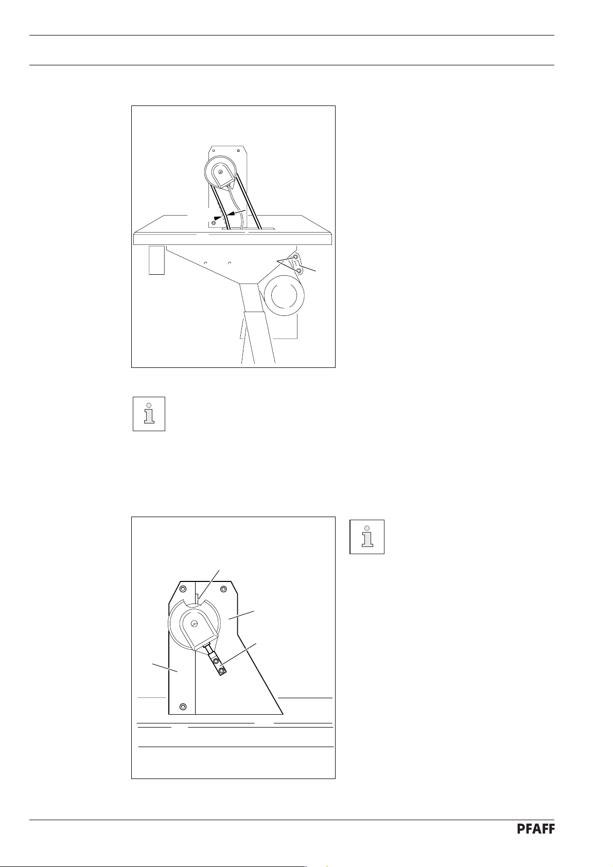
8.01.02 Adjusting the V-belt tension
● Loosen nuts 1.
● Tighten the V-belt with belt take-up
● Tighten nuts 1.
2 cm
1
2
hanger 2.
Fig. 8 - 02
Fig. 8 - 02 shows a Quick motor. If another motor is used, proceed as described
in the motor’s instruction manual.
8.01.03 Mounting the upper V-belt guard
1
3
2
If a large balance wheel is used,
the corner 1 of the belt guard 3
must be broken out.
● Screw position stop 2 to the belt guard
section 3.
● Attach belt guard section 3.
● Attach belt guard section 4.
8 - 2
4
Fig. 8 - 03
Page 25
Mounting and commissioning the machine
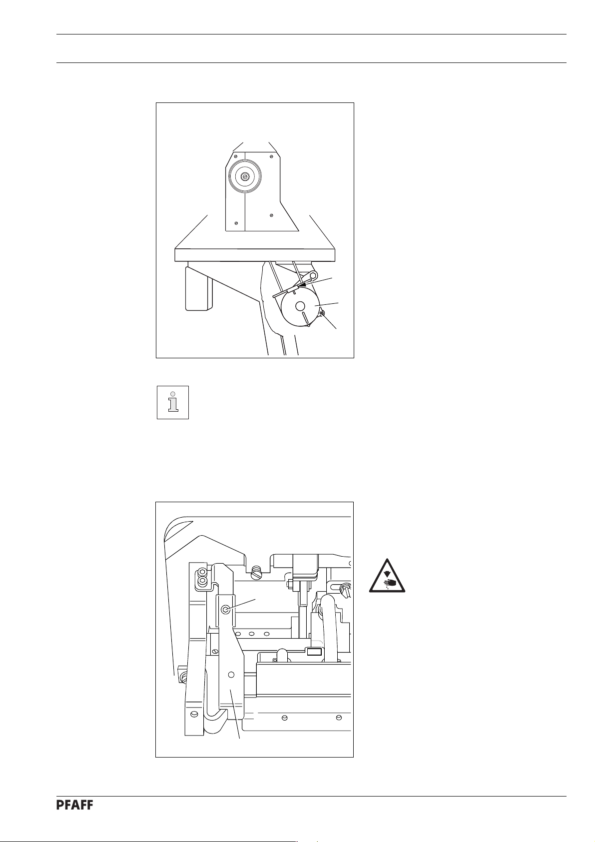
8.01.04 Mounting the lower V-belt guard
● Align belt-guard 7 in such a way that both
the motor pulley and the V-belt run freely.
● Tighten screws 8.
8
7
8
Fig. 8 - 04
Fig. 8 - 04 shows a Quick motor. If another motor is used, proceed as described
in the motor’s instruction manual.
8.01.05 Mounting tilt-over safeguard
2
● Screw-mount tilt-over safeguard 1
included in the accessories with screw 2.
Do not operate the machine
without tilt-over safeguard 1!
Danger of crushing between
upper part and table top!
Fig. 8 - 06
1
8 - 3
Page 26

Mounting and commissioning the machine
8.01.06 Mounting the spool holder
● Mount the spool holder as shown in
● Insert spool holder in the table-top hole
Fig. 8 - 05.
and fasten it by means of the included
nuts.
Fig. 8 - 05
8.01.07 Mounting the sewing lamp
● Screw the sewing lamp onto the table top (wood screws 5x35) and have it connected by
a specialist.
▲
The sewing lamp is not included in the normal delivery package.
▲
8 - 4
Page 27
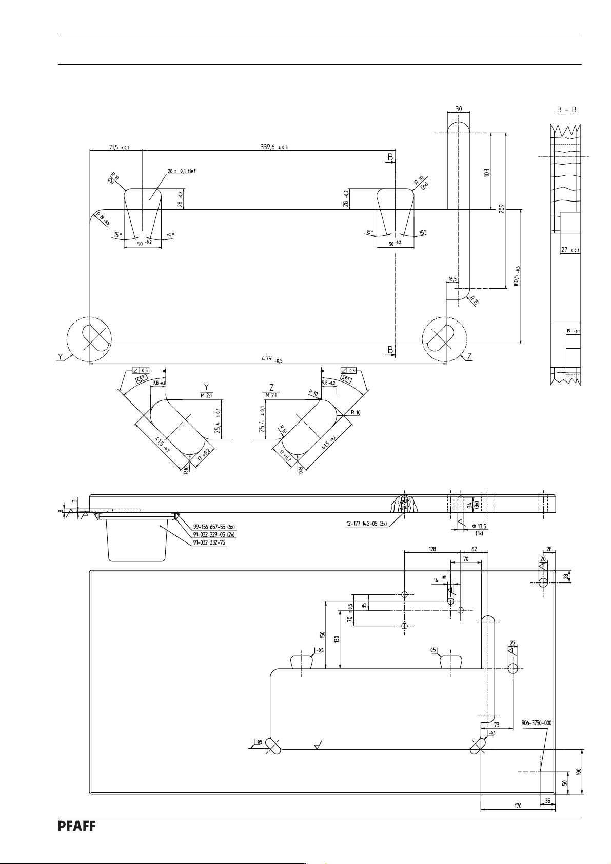
8.02 Table top cutout
8.02.01 PFAFF 1245
Mounting and commissioning the machine
Stand
position
8 - 5
Page 28

Mounting and commissioning the machine
8.02.02 PFAFF 1246
8 - 6
Gestell
Page 29
Mounting and commissioning the machine
8.03 Commissioning the machine
● Before commissioning the machine, check the electrical leads and pneumatic hoses for
any damage.
● Remove pin 1 of the oil reservoir 2 (Fig. 8 - 06). The pin serves only to protect the machine
from damage during transport and must not be used when sewing.
● Clean the machine thoroughly and oil it (see chapter 10 Care and maintenance)
● Have specialists ensure that the machine’s motor can be operated with the available
electricity supply and that it is connected correctly to the terminal box. If not, the machine
must not be operated.
● The handwheel must rotate towards the operator when the machine is running, if not, have
the motor re-adjusted converted by a specialist.
● Connect the machine to the compressed air system. The pressure gauge must display a
pressure of approx. 6 bar. If not, adjust the pressure to this value (see chapter 10.07
Checking the air pressure).
1
Fig. 8 - 06
8.04 Switching the machine on/off
● Switch on the machine (see chapter 7.01).
● Carry out a test run.
2
8 - 7
Page 30

Preparation
9 Preparation
9.01 Inserting the needle in the PFAFF 1245
All regulations and instructions in this Instruction manual are to be observed!
Special attention is to be paid to all Notes on Safety!
All preparation work is only to be carried out by appropriately trained personnel.
Before all preparation work, the machine is to be switched off via the on/off
switch or to beseparated from the electricity supply by removing the plug from
the mains!
Fig. 9 - 01
Turn the machine off!
Use only system 134 - 35 needles!
● Loosen needle retaining screw 1.
● Insert the needle as far as possible (the
long needle-groove must be f acing left).
● Tighten needle retaining screw 1.
The selection of the correct
needle depends on the model of
1
the machine and the material and
threads being sewn.
9 - 1
Page 31
9.02 Inserting the needle in the PFAFF 1246
1
Preparation
Turn the machine off!
Use only system 134 - 35 needles!
● Loosen needle retaining screws 1.
● Insert needles as far as it will go (the
longitudinal needle groove of the left-hand
needle must be pointing to the right and
that of the right-hand needle to the left).
● Tighten needle retaining screws 1.
Fig. 9 - 01a
1
The selection of the correct
needle depends on the model of
the machine and the material and
threads being sewn.
9 - 2
Page 32

Preparation
9.03 Winding the bobbin thread, adjusting the thread tension
4
6
1
3
2
Fig. 9 - 02
● Place an empty bobbin 1 onto bobbin shaft 2.
● Thread the bobbin in accordance with Fig. 9 - 02 and wind it clockwise around bobbin 1
a few times.
● Switc h on the bobbin winder while at the same time pressing bobbin winder spindle 2
and lever 3.
The bobbin fills up while you are sewing.
● The tension of the thread on bobbin 1 can be adjusted with knurled screw 4.
● The bobbin winder stops automatically when bobbin 1 is full.
5
9 - 3
If the thread is wound unev enly:
● Loosen nut 5.
● Turn the thread guide 6 accordingly.
● Tighten nut 5.
Page 33

9.04 Removing/Threading the bobbin case
Preparation
Fig. 9 - 03
1
2
Removing the bobbin case.
● Open the bed slide.
● Raise latch 1 and remove bobbin
case 2.
Inserting the bobbin case.
● Insert bobbin case 2 so that it clicks into
place.
● Close latch 1 and close the bed slide.
Turn the machine off!
9.05 Inserting the bobbin case / Adjusting the bobbin thread tension
Turn the machine off!
5 cm
1
Fig. 9 - 04
Threading the bobbin case.
● Thread the bobbin as shown in
Fig. 9 - 04.
● When the thread is pulled, the bobbin
must rotate in the direction of the arrow.
Regulating the bobbin thread tension.
● Regulate the bobbin thread tension with
screw 1.
9 - 4
Page 34
Preparation
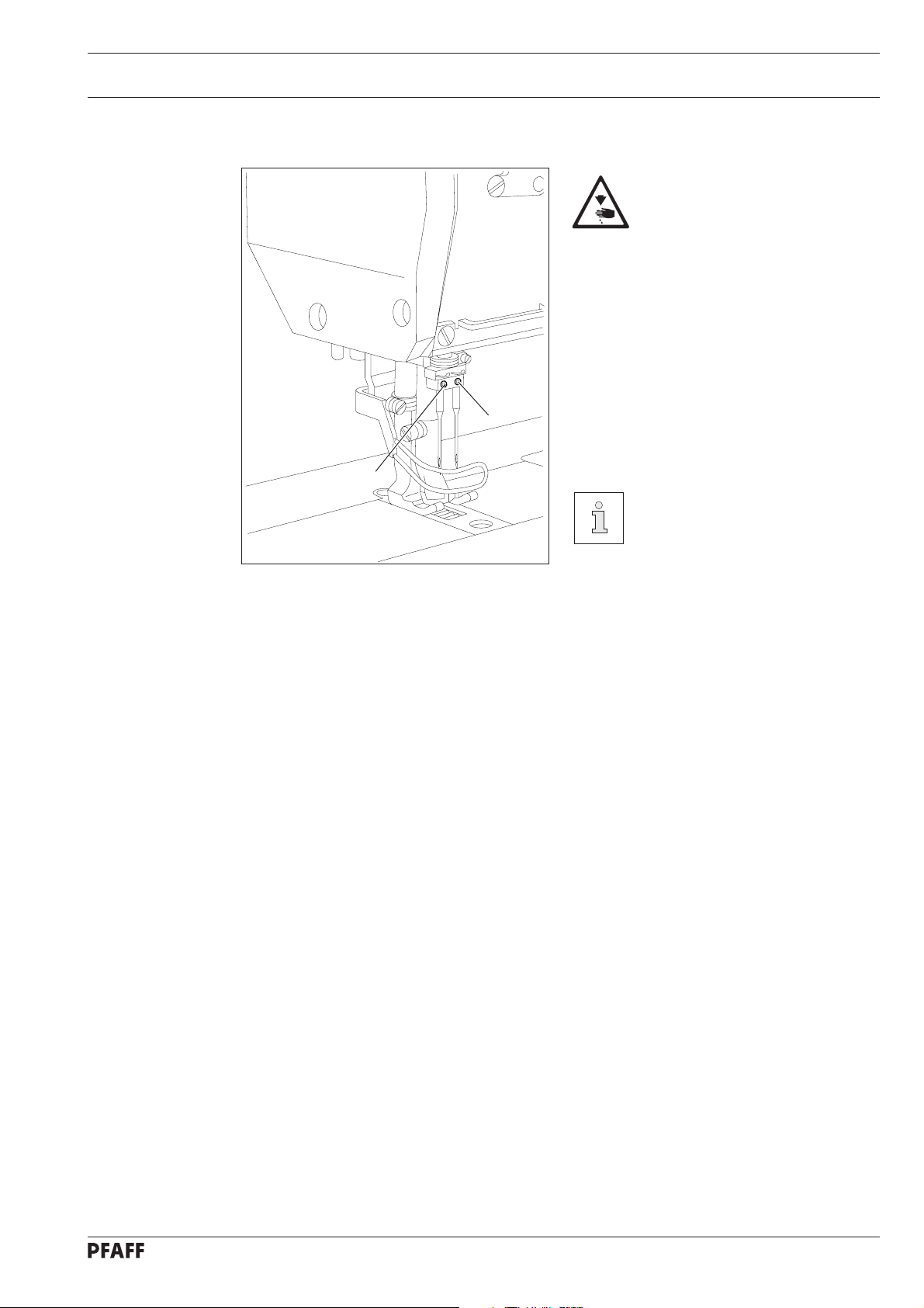
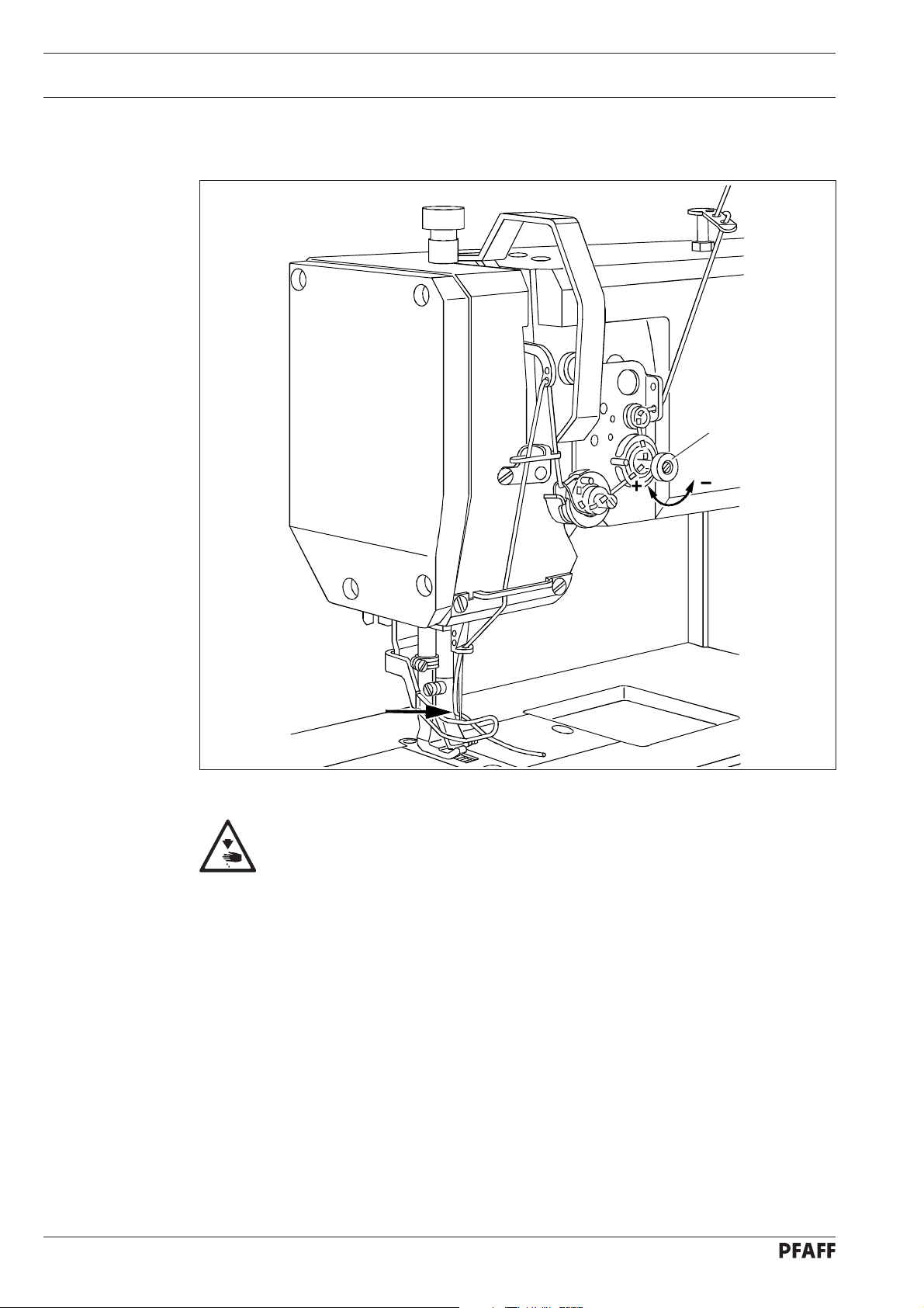
9.06 Threading the needle thread / Adjusting the needle thread tension in the
PFAFF 1245
1
Fig. 9 - 05
Turn the machine off!
● Thread the machine as shown in Fig. 9 - 05. T ak e note that the needle is threaded from
the lef t (see arrow).
● Adjust the needle thread tension by turning knuled scre ws 1..
9 - 5
Page 35
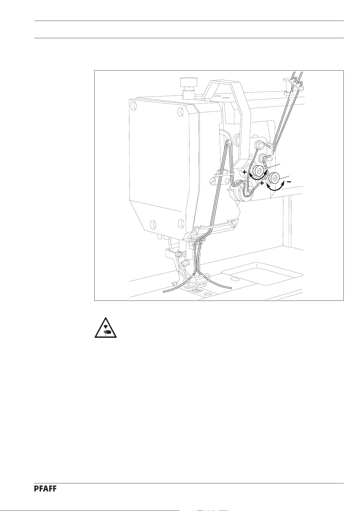
Preparation
9.07 Threading the needle thread / Adjusting the needle thread tension in the
PFAFF 1246
1
1
Fig. 9 - 06
Maschine ausschalten!
● Thread the machine as shown in Fig. 9 - 06. Care must be taken that the left-hand needle
is threaded from the right and the right-hand needle is threaded from the left.
● Adjust the needle thread tension by turning knurled scre ws 1.
9 - 6
Page 36

Care and maintenance
10 Care and maintenance
10.01 Servicing and maintenance intervals
Check the air pressure ............................................................................. daily before use
Clean the hook compartment ........................ daily, more often if in continuous operation
Check the water container of the air filter................................................ daily before use
General lubrication ....................................................................................... twice a week
Lubricate the front parts .............................................................................. twice a week
Check the hook oil-container......................................................................... once a week
Clean the hook.............................................................................................. once a week
Lubricate the top-feed drive eccentric.................................................................. Annually
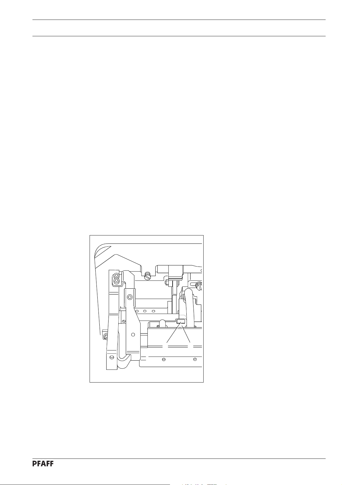
10.02 Cleaning
Fig. 10 - 01
● When inserting the bobbin case, ensure that horn 5 meshes in the groove of the needle
plate (see arrow).
● Finally, screw hook gib 1 back on.
● Insert the bobbin case and close the bed slide.
These maintenance intervals are calculated for the average running time of a
single shift operation. If the machine is operated more than this, shorter
intervals are recommended.
32
5
41
Turn the machine off!
● Clean the hook compartment daily with a
brush, more often if in continuous
operation.
● Thoroughly clean the hook once a week.
● Open the bed slide.
● Bring the needle bar to its highest
position.
● Remove the bobbin case cap and the
bobbin.
● Unscrew hook gib 1.
● Turn the handwheel until point 2
penetrates into groov e 3 approx. 5 mm.
● In this position, remove bobbin case 4.
● Clean the hook race with paraffin.
10 - 1
Page 37

10.03 General lubrication
Care and maintenance
1
Fig. 10 - 02
Only use oil with a mean viscosity of 22.0 mm2/s at 40°C and a density of
0.865 g/cm3 at 15°C.
We recommend PFAFF sewing machine oil. Part no. 280-1-120 144.
Fig. 10 - 03
10 - 2
Page 38

Care and maintenance
Turn the machine off!
● Lubricate all bearings marked in Fig. 10.02 twice a week.
● Open the bed slide to gain access to oiling point 1.
● Pull the knee lever out to the front and lay the machine on its back.
● Lubricate all bearings marked in Fig. 10.03 twice a week.
Setting the machine upright
● Hold the machine, press tilt safety device 3 (Fig. 10-04) and ret urn the machine to an
upright position with both hands.
Danger of crushing between machine and table top!
10.04 Lubricating the hook
Turn the machine off!
● Pull the knee lev er out to the front and
lay the machine on its back.
● Fill oil reservoir 1 through hole 2 up till
the topmost marking.
Setting the machine upright
● Hold the machine, press tilt safety
device 3 and return the mac hine to an
1
2
upright position with both hands.
10 - 3
Fig. 10 - 04
Danger of crushing between
machine and table top!
3
Page 39
10.05 Lubricating the head
Care and maintenance
Turn the machine off!
● Unscrew the face plate.
● Lubricate all bearings and moving parts
marked in Fig. 10 - 05 twice a w eek.
● Screw the face plate back on.
Only use oil with a mean
viscosity of 22.0 mm2/s at 40°C
and a density of 0.865 g/cm
at 15°C.
We recommend PFAFF sewing
machine oil. Part no.
280-1-120 144.
3
Fig. 10 - 05
10.06 Lubricating the top-feed drive excentric
● Open cover 1 on the back of the
● Grease nipple 2 at least once a year (use
● Screw cover 1 back on.
2
1
Turn the machine off!
machine.
grease gun).
Only use lithium base grease
with a dripping point of 185°C
and a worked penetration of
22-25 mm at 25°C.
Fig. 10 - 06
We recommend Pfaff
sewingmachine grease Part no.
280-1-120 247.
10 - 4
Page 40

Care and maintenance
10.07 Checking the air pressure
1
● Before each use of the machine, check
the air pressure on gauge 1.
2
● The gauge must display a pressure of
6 bar.
● If necessary, alter the pressure to this
level.
● To do so, lift button 2 and turn it so that
the gauge shows a pressure of 6 bar.
● Press but ton 2 back down again.
Fig. 10 - 07
10.08 Emptying / Cleaning the water container of the air filter
Turn the machine off!
Remove the compressed-air hose
from the air filter.
Emptying the water trap
● Water trap 1 empties itself automatically
when the compressed-air hose is
removed from the air filter.
10 - 5
Fig. 10 - 08
Cleaning the filter
● Unscrew water trap 1 and filter 2.
● Clean the filter with compressed air or
2
max.
1
with isopropyl alcohol, Part number
95-665 735-91.
● Screw filter 2 back in and water trap 1
back on.
Page 41

11 Adjustment
The illustrations in this section show the PFAFF 1245 single-needle machine.
For the PFAFF 1246 two-needle mac hine, various adjustments must be made
twice, i.e. to the left- and right-hand sewing hooks. This will be pointed out in
the respective sections, whereby it is often possible to apply the mirror image
of the illustrations.
11.01 Tools, gauges and other accessories for adjusting
● Screwdrivers with blade widths from 2 to 10 mm
● Screwdrivers with blade widths from 7 to 14 mm
● Allan keys from 2 to 6 mm
● Metal rule, (Part No. 08-880 218-00)
● Adjustment gauge, (Part No. 08-880 136-14)
● Adjustable clamp, (Part No. 08-880 137-00)
● Gauge, (top feed stroke 7 mm) (Part No. 61- 111 630-14)
● Needles, system 134-35
● Sewing thread and test material
Adjustment
11.02 Notes on adjusting
All adjustments in these adjustment instructions are based on a completely installed
machine and must only be carried out by appropriately trained specialists. Covers on the
machine which have to be removed and replaced for checks and adjustment work are not
mentioned here. The screws and nuts in brackets ( ) are attachments of machine parts which
are to be loosened before making the adjustment and tightened again when the adjustment
is complete.
11.03 Abbreviations
TDC = top dead center
BDC = bottom dead center
11 - 1
Page 42

Adjustment
11.04 Adjusting the basic machine
11.04.01 Positioning the feed dog across the direction of sewing
Requirement
The bottom feed dog must be the same distance from the left and right side of the needleplate cutout.
X
4
Fig. 11 - 01
● Loosen screws 1 and 2.
● Laterally align rock shaft 3 in accordance with the requirement.
● Now tighten scre ws 1.
1
X
4
1
23
11 - 2
The flat sides of pins 4 must be opposite the flat sides of screws 1 and rock
shaf t 3 must exhibit neither play nor stiffness.
● Screws 2 remain loose for the follo wing adjustments.
Page 43
11. 04.02 Positioning the feed dog in the direction of sewing
Requirement
With the longest stitch set, the bottom feed dog must have the same clearance the front
and the back with respect to the needle-plate cutout when feeding both forwards and
backwards.
X
Adjustment
Fig. 11 - 02
X
2
1
● Set the longest stitch.
● Adjust rock shaft 1 in accordance with the requirement and tighten screws 2.
11 - 3
Page 44

Adjustment
11.04.03 Height of the bottom feed-dog
Requirement
With the stitch length set at „0“, the bottom feed dog must protrude over the needle plate
as high as the teeth when at TDC.
2
1
11 - 4
Fig. 11 - 03
● Set stitch length „0“.
● Bring the bottom feed dog to its TDC by turning the handwheel.
● Adjust feed dog carrier 1 (screws 2) in accordance with the requirement.
If required, the feed dog height can be reduced a little on machines without a
bottom feed lifting phase (without P).
Page 45

11. 04.04 Pre-adjusting the needle height
Requirement
With the needle bar at BDC, the distance between the needle bar and the needle plate
must be 15 mm.
Adjustment
2
1
15 mm
Fig. 11 - 04
● Move needle bar 1 (screw 2) in accordance with the requirement without moving it
laterally.
11 - 5
Page 46

Adjustment
11. 04.05 Centering the needle in the needle hole
Requirement
With the stitch length set at „0“, the needle must enter the needle hole exactly in the
middle.
4
3
7
6
8
5
1
9
2
Fig. 11 - 05
● Unscrew vibrating presser 1 and presser foot 2.
● Set stitch length „0“ and bring the needle bar to its TDC.
● Insert a new needle. Loosen screws 3, 4, 5 and 6.
● Position the needle directly over the bottom feed dog by turning the handwheel.
● Move needle bar frame 7 in accordance with the requirement.
● Tighten screws 3, 4 and 5.
● Position stop 8 so that it is touching needle bar frame 7 and tighten screw 6.
11 - 6
The movement of needle bar frame 7 in guide 9 and of the top f eed drive bars
must not be stiff.
Page 47

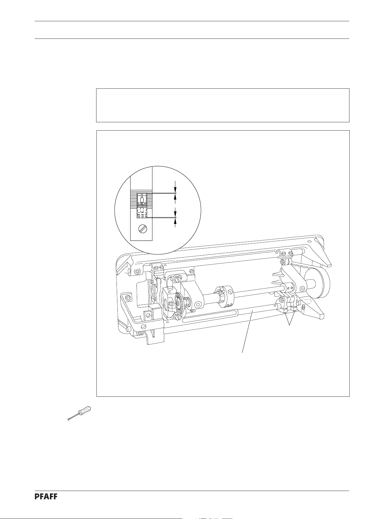
11. 04.06 Lifting motion of the bottom feed-dog
This adjustment does not apply for machines without a bottom feed lifting phase (without P).
Requirement
1. With the needle bar at its BDC, the bottom feed dog must be at its TDC.
2. With the longest stitch set, the bottom feed dog must reach the top surface of the
needle plate at the same time as the needle point when the handwheel is turned.
Adjustment
21
Fig. 11 - 06
● Bring the needle bar to its BDC.
● Turn f eed lifting eccentric 1 (screws 2) in accordance with requirement 1.
● In this position, tighten the accessible screw 2 until feed lifting eccentric 1 can be turned
with difficulty.
● Turn feed lifting eccentric 1 a little further in accordance with requirement 2.
● Tighten both screws 2.
11 - 7
Page 48

Adjustment
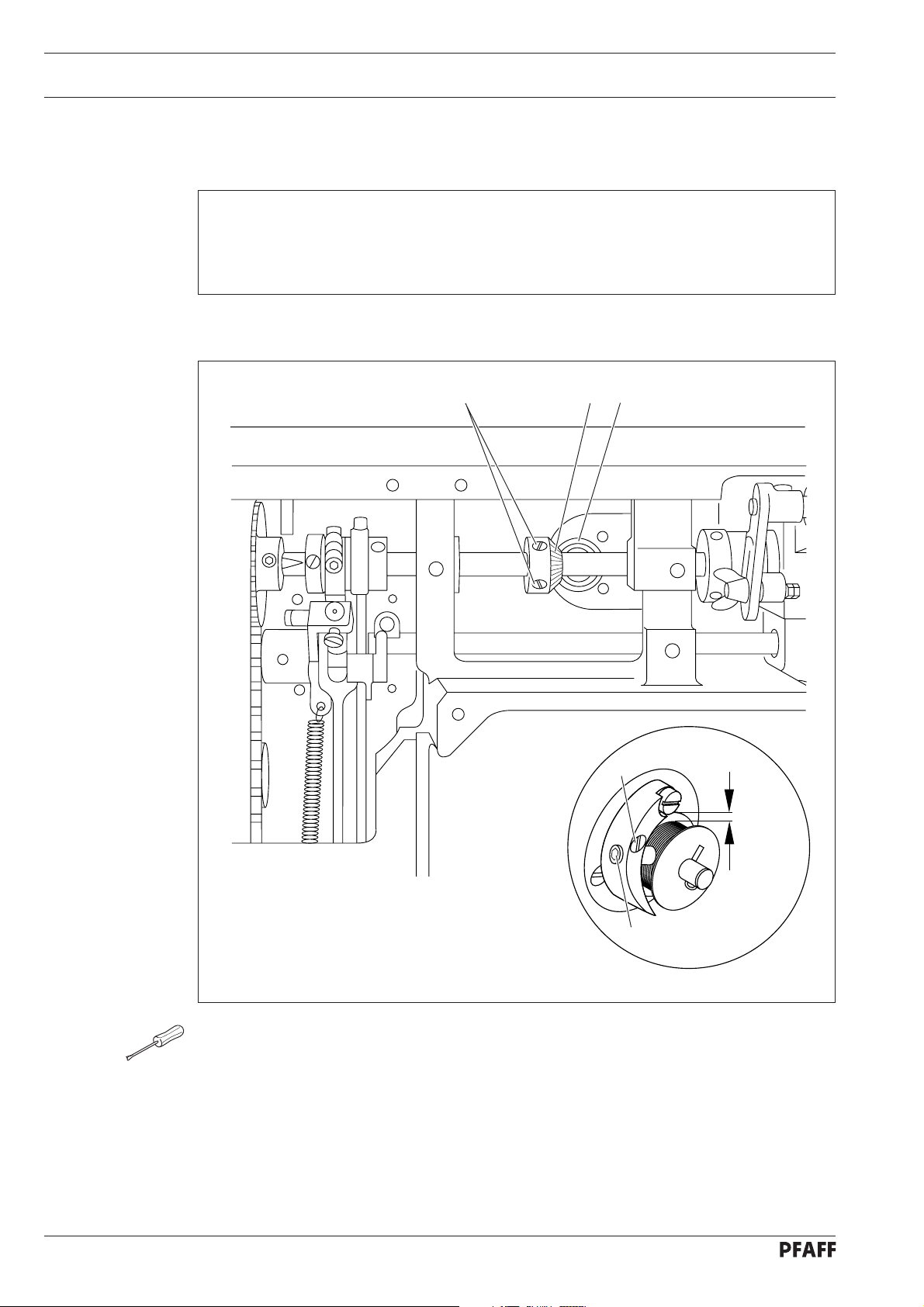
11. 04.07 Driving motion of the bottom and top feeds
Requirement
With the longest stitch length set and the needle bar at its BDC, the top and bottom feeds
should not move when the reverse-feed lever is activated.
2
1
11 - 8
Fig. 11 - 07
● Set the longest stitch.
● Loosen screws 1 just f ar enough so that the feed driving eccentric 2 can be turned on
the shaft with difficulty.
● Bring the needle bar to its BDC.
● Turn the feed driving eccentric 2 so that its eccentricity is facing downwards.
● Now turn it a little in the direction of rotation in accordance with the requirement.
● In this position, tighten screws 1.
● Carry out a check in accordance with the requirement.
Page 49

Adjustment
11. 04.08 Hook-to-needle clearance, needle rise, needle height and needle guard
(On Model 1246 make these adjustments on both sewing hooks.)
Requirement
With the stitch length set at „3“ and the needle rise at (1.8 mm after BDC of the needle
bar on model „B“ and 2.0 mm after BDC of the needle bar on model „C“), the following
must be true:
1. The distance to the needle must be 0.05 - 0.1 mm and the hook point must be pointing
to the middle of the needle.
2. The top edge of the eye of the needle must be 0.8 - 1 mm below the hook point.
3. The needle guard must lightly touch the needle.
0.05 - 0.1 mm
4
1
1
2
5
0.8 - 1 mm
3
Fig. 11 - 08
● Set stitch length „3“ and loosen screws 1 and 2 (also loosen screws 3 on mac hines with
automatic thread trimmer -900/56).
● Move hook bearing 4 in accordance with requirement 1.
● Tighten screws 1.
● Bring the needle to its BDC and slide the 1.8 or 2 mm thick feeler gauge under the
needle bar bearing, allow the adjustable clamp to come to rest on the feeler gauge and
screw it tight.
● Remove the feeler gauge and turn the handwheel in its direction of rotation until the
11 - 9
Page 50

Adjustment
4
1
1
2
5
5
7
6
3
Fig. 11 - 08
adjustable clamp is touching the needle bar bearing.
● Position the hook point at the middle of the needle, taking care to ensure that the needle
is not pressed by needle guard 7.
● While ensuring that bevel pinion 5 is not too close, and that the hook does not exhibit too
muc h play, tighten screws 2.
● On machines with automatic thread trimmer -900/56, bring retaining collar 6 to rest on
bevel pinion 5 and tighten screws 3.
● Adjust the needle height in accordance with requirement 2 (see also chapter 11.04.04).
● Align needle guard 7 in accordance with requirement 3.
Bei der PFAFF 1246 ist nach Veränderung des Nadelabstandes unbedingt die
V erbindungsstange zum Fadenabschneider (siehe auc h Kap.11.05.10)
neu zu justieren.
11 - 10
Page 51

11. 04.9 Top-feed stroke
Requirement
At the largest top-feed stroke setting and stitch length „0“, presser foot 1 and vibrating
presser foot 2 must lift 7.0 mm from the needle plate when the handwheel is turned.
4
Adjustment
3
Fig. 11 - 9
7 mm
2
7 mm
1
● Set the largest top-feed stroke and the stitch length at „0“.
● Bring presser foot 1 to rest on the needle plate.
● Turn the handwheel in the direction of rotation until vibrating presser foot 2 has reached
its highest point.
● Turn crank 3 (screws 4) in accordance with the requirement.
● Carry out a check in accordance with the requirement.
11 - 11
Page 52

Adjustment
11. 04.10 Lifting motion of the top feed
Requirement
When presser foot 1 is resting on the needle plate, the vibrating presser foot 4 and the
point of the needle must both reach the needle plate at the same time when the top feed
stroke is set at maximum.
2 3
1
4
Fig. 11 - 10
● Allow presser foot 1 to rest on the needle plate.
● Loosen screws 2 until feed lifting eccentric 3 can be turned on its shaft with difficulty.
● Turn feed lifting eccentric 3 in accordance with the requirement.
● Tighten screws 2.
● Carry out a check in accordance with the requirement.
11 - 12
Page 53

11. 04.11 Bobbin-case opener
(On Model 1246 make these adjustments on both bobbin openers.)
Requirement
The needle thread must not be clamped between the bobbin-case opener 1 and the bobbin-case base 3 nor may it be clamped between projection 4 and the retaining trip of the
needle plate (see arrows).
4
Adjustment
2
3
1
Fig. 11 - 11
● Thread the machine, insert test material and allow the presser foot to rest on the needle
plate.
● Sew a few stitches by turning the handwheel and carry out a check in accordance with
the requirement.
● Turn bobbin-case opener 1 (screw 2) in accordance with the requirement.
11 - 13
Page 54

Adjustment
11. 04.12 Safety clutch
The safety clutch is set by the manufacturer and screws 5 are sealed.
If the thread jams, the safety clutch snaps out to prevent damage to the hook.
A description of how to snap the clutch back in follows.
3
4
2
1
5
11 - 14
Fig. 11 - 12
● Remove the jammed thread.
● Press piston 1 and t urn the handwheel until hook 3 of pa wl 2 clicks into groov e 4.
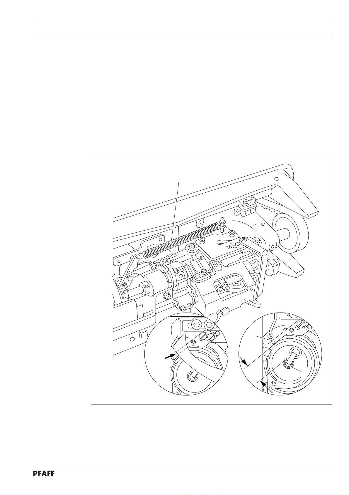
Page 55
11. 04.13 Needle thread tension release
Requirement
With the presser foot raised, both of the tension discs must be at least 0.5 mm apart.
The clearance of 0.5 mm is a minimum and can increase to more than 1 mm
when using thick threads.
Adjustment
3
1
2
0.5 mm
Fig. 11 - 13
● Align pressure plate 1 behind tension carrier plate 2 in accordance with the requirement.
If the tension is correct, release pin 3 must not be under pressure.
11 - 15
Page 56

Adjustment
11. 04.14 Thread check spring
Requirement
The movement of thread check spring 2 must be finished when the needle point enters the
material (approx. 7 mm spring path).
Due to technical reasons, the length of the thread-check spring path can vary a
little in either direction.
7 mm
2
3
1
Fig. 11 - 14
● Thread the machine, place test material under the presser foot and allow the presser
foot to rest on the fabric using the presser foot lifter.
● Loosen screw 1.
● Sew a few stitches by turning the handwheel and then bring the take-up lever to its TDC.
● Continue to turn the handwheel (in its direction of rotation) until the needle enters the
material.
● In this position, bring stop 3 to rest on thread check spring 2 and tighten screw 1.
11 - 16
Page 57

Adjustment
11. 04.15 Thread check spring on PFAFF 1246 with thread trimmer -900/56
Requirement
The motion of thread controller springs 1 and 6 should cease as soon as the needle point
penetrates the material (= about 7 mm spring deflection).
Due to technical reasons, the length of the thread-check spring path can vary a
little in either direction.
Fig. 11 - 14a
7 mm
1
4
6
9
7
2
8
10
5
3
● Turn screw 2 (scre w 3) to adjust the spring resistance of thread check spring 1.
● Turn retainer 4 (screw 5) according to the requirement.
● Turn scre w 7 (screw 8) to adjust the spring resistance of thread check spring 6.
● Turn retainer 9 (screw 10) according to the requirement.
11 - 17
Page 58
Adjustment
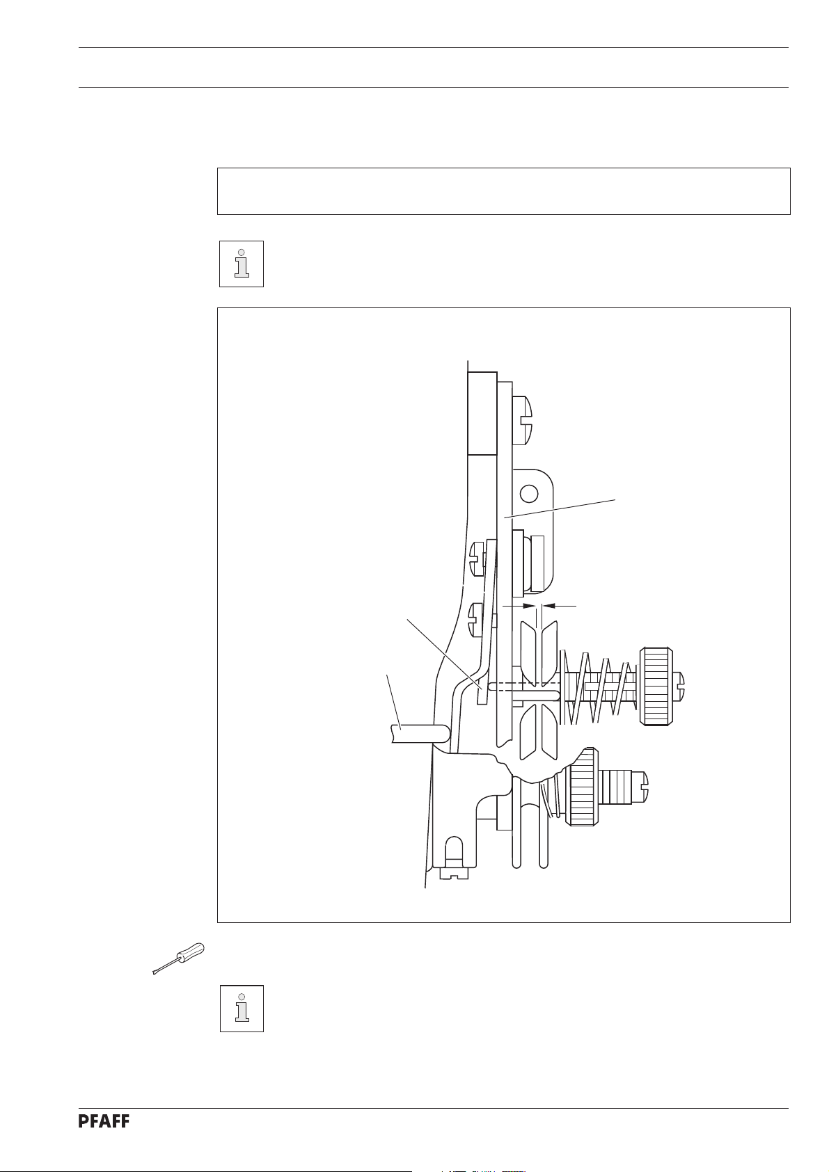
11. 04.16 Bobbin winder
Requirement
1. With the bobbin winder switched on, the bobbin winder spindle must engage reliably.
With the bobbin winder switched of f, friction wheel 5 must not touch driv e wheel 1.
2. The bobbin winder must switch off automatically when the thread level is approximately
1 mm from the edge of the bobbin.
2 1 5
4
1 mm
3
Fig. 11 - 15
● Move drive wheel 1 (screws 2) in accordance with requirement 1.
● Place a bobbin on the bobbin winder, thread the bobbin and switch on the bobbin winder.
● Move stop latch 3 (screws 4) in accordance with requirement 2.
11 - 18
Page 59
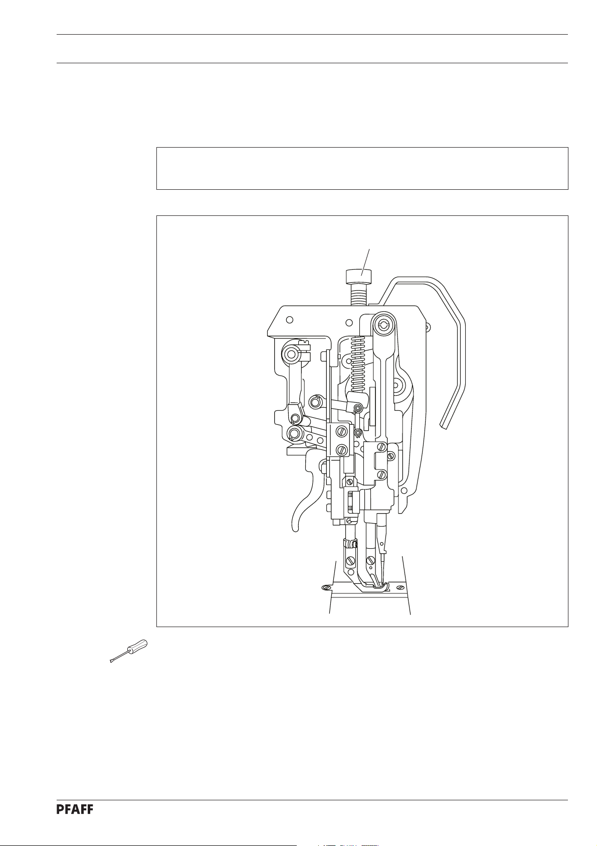
11. 04.17 Presser-foot pressure
Requirement
The material must be fed reliably even at top sewing-speed. There mustn’t be pressure
marks on the material.
Adjustment
1
Fig. 11 - 16
● Turn screw 1 in accordance with the requirement.
11 - 19
Page 60

Adjustment
11.05 Adjusting the thread trimmer -900/56
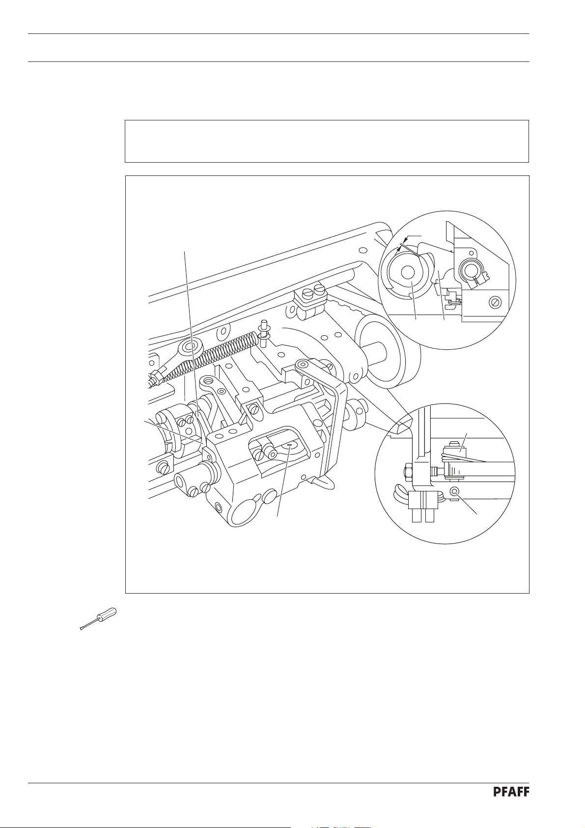
11.05.01 Pre-adjusting the control cam
Requirement
1. The eccentric bearing-surf ace of control cam 5 must be laterally in the middle of pa wl 8.
2. With the take-up lever at its TDC, the beginning of the largest eccentricity of the
bearing surface (in the direction of rotation) must be underneath the point of pawl 8.
4
3
4
1
8
8
5
5
6
5
2
8
7
Fig. 11 - 17
● Remove catch 1 (screws 2).
● Remov e plate 3 (screws 4).
● Loosen the four screws of control cam 5 and screws 6 of retaining collar 7.
● Move control cam 5 laterally in accordance with requirement 1.
● In this position bring retaining collar 7 to rest on control cam 5 and tighten screws 6.
● Bring the take-up lever to its TDC by turning the handwheel.
● Turn control cam 5 in the direction of rotation in accordance with requirement 2, taking
care to note that it is touching retaining collar 7.
● In this position, tighten the four screws on control cam 5.
11 - 20
Page 61

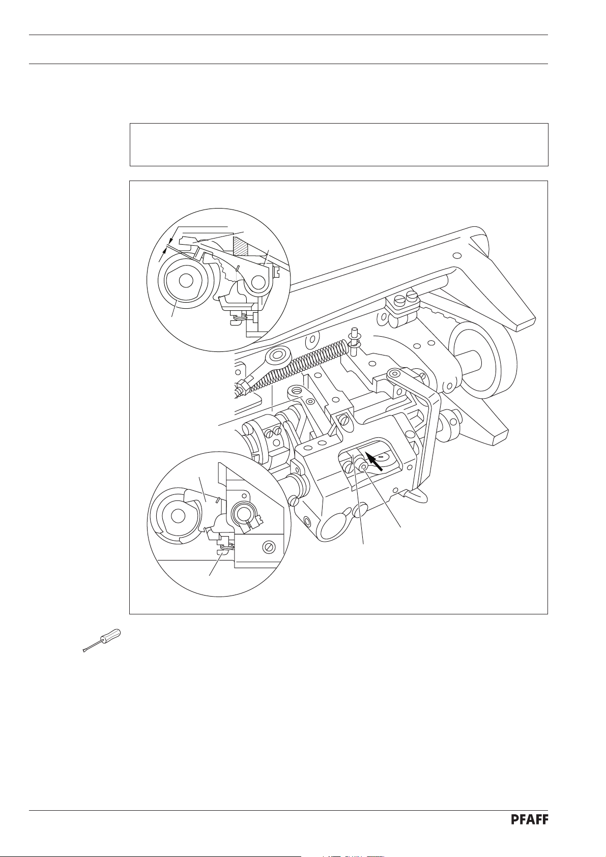
11. 05.02 Tripping lever
Requirement
In needle rise position, the flattened pin of control le ver 6 (see arrow) must fall slightly into
the track of control cam 7 when activating lev er 8 is activ ated.
Adjustment
6
1
2
6
7
5
7
3
4
8
Fig. 11 - 18
● Screw out screw 1 and swing out connecting rod 2.
● Loosen screws 3 and 4.
● Bring the needle bar to needle rise position by turning the handwheel.
● Bring clamp 5 to rest on the right side of the housing.
● Keeping this position, move control lever 6 laterally in accordance with the requirement
and then press control lev er 6 onto the bottom of the cam track.
● In this position, tighten screw 3.
● Carry out a check in accordance with the requirement.
● Screw 4 remains loosened until the release trip is adjusted.
11 - 21
Page 62
Adjustment
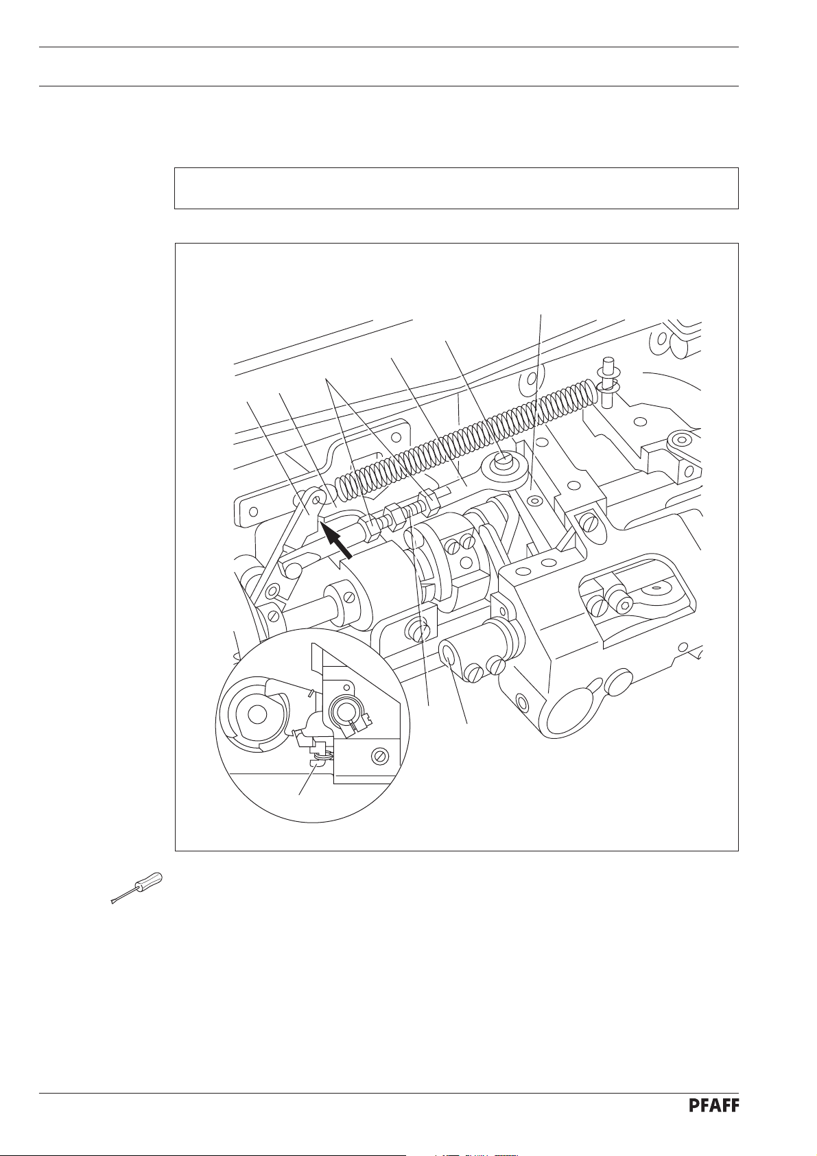
11. 05.03 Pawl
Requirement
With the cut-off mechanism in resting position, there must be a distance of 0.3 mm
between the largest eccentricity of bearing surface 1 and pawl 2.
0.3 mm
2
2
1
1
3
Fig. 11 - 19
● Position the largest eccentricity of bearing surface 1 underneath pawl 2 by t urning the
handwheel.
● Move bearing bolt 3 (screw 4) in accordance with the requirement.
3
4
11 - 22
Page 63

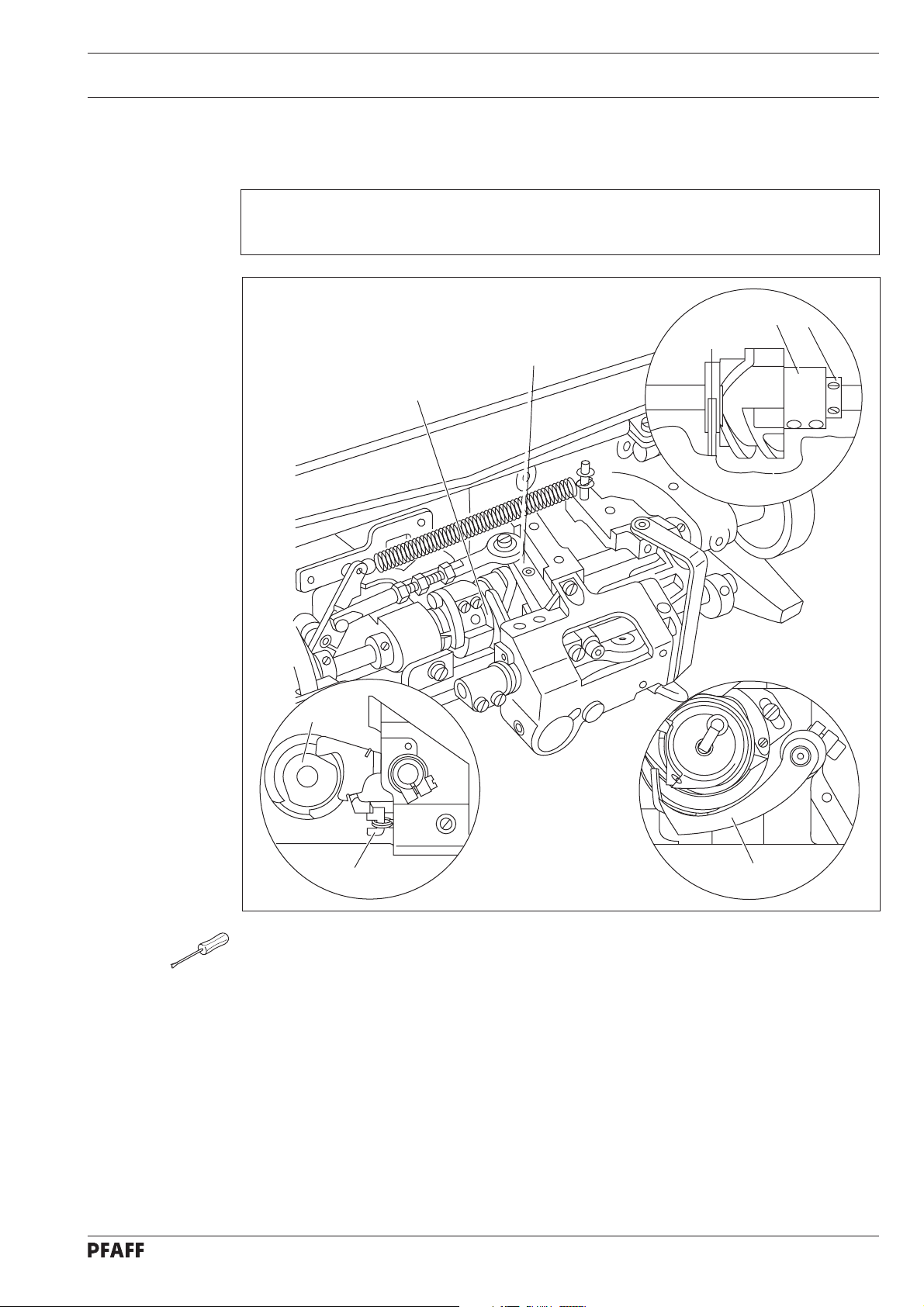
11. 05.04 Engaging solenoid
Requirement
In needle rise position and with engaging solenoid 5 activated, there must be a distance
of 0.3 mm between engaging lever 2 and pawl 3.
Adjustment
3
4
5
1
5
2
0.3 mm
Fig. 11 - 20
● Bring the machine to needle rise position by turning the handwheel.
● Loosen screw 1 until the engaging solenoid can be turned with difficulty.
● Manually activate engaging lever 2 so that pawl 3 engages.
● Press magneto inductor 4 as far as possible into solenoid housing 5 and move both the
solenoid housing and the magneto inductor in accordance with the requirement.
● In this position tighten screw 1.
11 - 23
Page 64
Adjustment
11. 05.05 Release trip
Requirement
In needle rise position and with control lev er 4 engaged, there must be a distance of
approx. 0.3 mm between the bolt of the control lever and the base of the cam track.
0.3 mm
4
6
5
4
2
3
6
1
Fig. 11 - 21
● Bring the machine to needle rise position by turning the handwheel.
● Manually activate engaging lever 1 so that pawl 2 engages.
● Taking care to ensure that screw 3 is still loose, press control le ver 4 down to the base
of the track of control cam 5.
● Maintaining this position, lightly tighten screw 3 while bringing release trip 6 into a
resting position against engaging lever 1 and laterally against control le ver 2 in the
direction of the arrow.
● By lightly tapping on release trip 6 in the direction of the arrow, while simultaneously
tapping control lever 4, create a distance between the bolt and the base of the cam track
which corresponds with the requirement.
● In this position tighten screw 3.
● Carry out a check in accordance with the requirement.
11 - 24
Page 65

11. 05.06 Engaging lever
Requirement
With the needle bar at TDC and with control lev er 3 at starting position, there must be a
distance of approx. 0.3 mm between bolt 4 and the outer diameter of control cam 5.
0.3 mm
5
3
Adjustment
4
3
5
Fig. 11 - 22
● Bring the needle bar to TDC by turning the handwheel.
● Turn screw 1 (nut 2) in accordance with the requirement.
● Carry out a chec k by tapping control lever 3.
1
2
11 - 25
Page 66
Adjustment
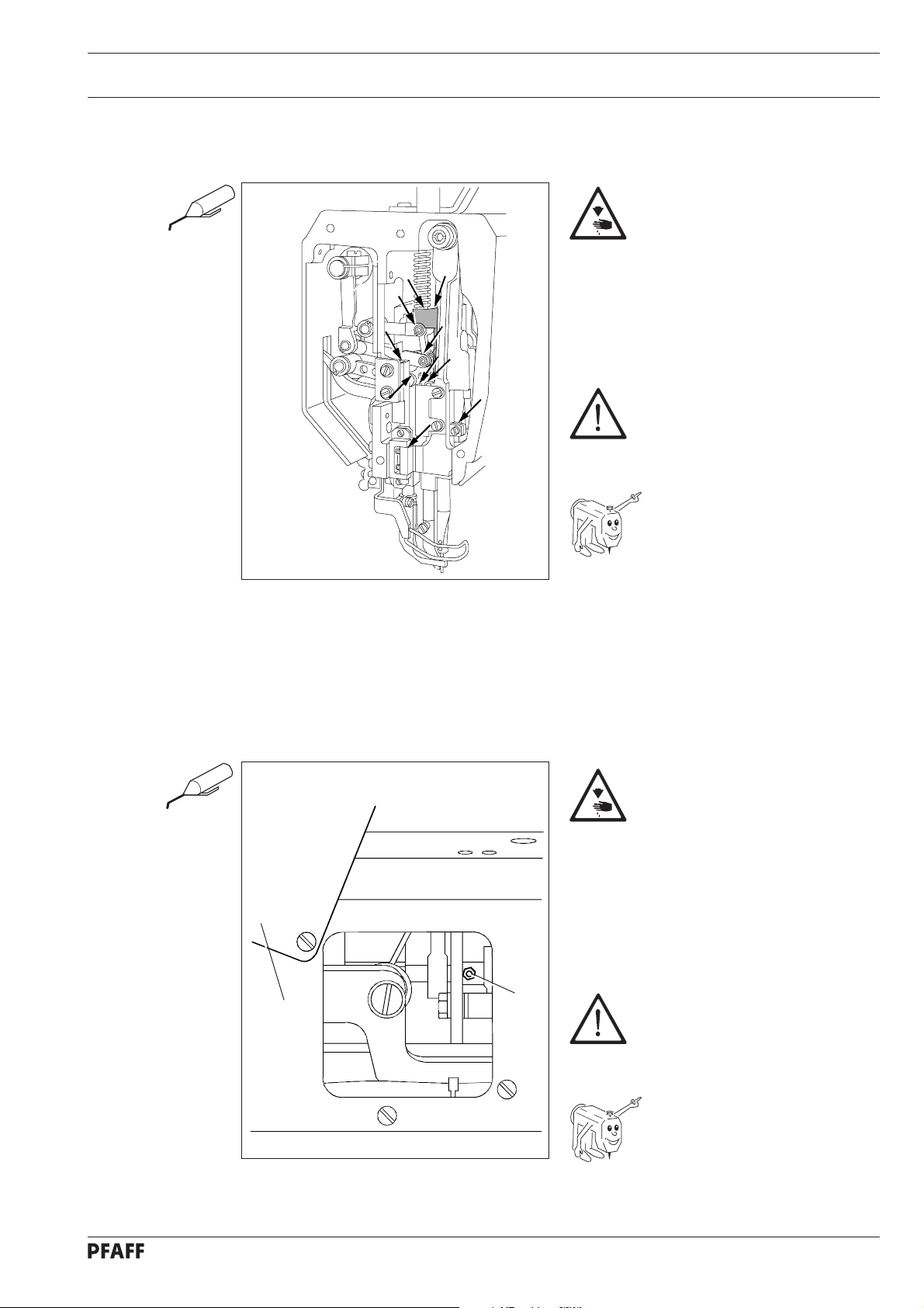
11. 05.07 Linkage rod
Requirement
When shaft 9 begins its sliding motion, le v er 6 must simultaneously lif t from stop 7.
3
2
1
4
7
6
11 - 26
8
9
5
Fig. 11 - 23
● Affix spherical head 1 to control lev er 3 using screw 2.
● Loosen nuts 4 (right and lef t handed thread).
● Bring the machine to needle rise position by turning the handwheel and activate
engaging lever 5.
● Taking care to ensure that lever 6 is touching stop 7 (see arrow), turn linkage rod 8 in
accordance with the requirement.
● In this position tighten both nuts 4.
● Carry out a check in accordance with the requirement.
Page 67
11. 05.08 Final adjustment of the control cam
Requirement
When control lever 3 is engaged and the needle point is 12 mm above the needle plate
coming from its BDC, the motion of the thread catc her 5 must begin.
1
3
Adjustment
1
4
1
2
Fig. 11 - 24
● Bring the take-up lever to just past its TDC by turning the handwheel and loosen the
accessible screws on control cam 1.
● Continue turning the handwheel in its direction of rotation until the machine is in needle
rise position and then activate engaging le ver 2.
● Taking care to ensure that control lev er 3 is engaged, loosen the remaining screws on
control cam 1.
● Continue turning the handwheel in its direction of rotation until the point of the needle is
12 mm above the needle plate.
● In this position, and taking care to ensure that control cam 1 is touc hing retaining collar
4, turn in the direction of rotation until you feel some resistance.
● In this position, tighten the accessible screws on control cam 1.
● Make the remaining screws on control cam 1 accessible and tighten these as w ell.
● Carry out a check in accordance with the requirement.
5
11 - 27
Page 68

Adjustment
11. 05.09 Catch
Requirement
With the cut-off mechanism in resting position, there must be a distance of approx. 5 mm
between catch 1 and control lever 6.
4
5
6
1
6
5 mm
1
2
3
Fig. 11 - 25
● Lightly affix catc h 1 and cover plate 2 using scre ws 3.
● Move catch 1 as far as possible in the direction of the arrow and then move it laterally in
accordance with the requirement.
● In this position, tighten screws 3.
● Using screws 5, screw plate 4 on.
11 - 28
Page 69

11. 05.10 Connecting rod (for PFAFF 1246 only)
Requirement
When the cut ting device is in the off-position, the length of spacer rod 4 should be equal to
the distance between shafts 2 and 3.
X
Adjustment
2
3
1
4
1
X
Fig. 11 - 25a
● Loosen nuts 1 (right- and lef t-hand thread) when the cutting de vice is in the off-position.
● Measure the distance between shafts 2 and 3.
● Rotate connecting rod 4 according to the requirement.
● Re-tighten nuts 1.
11 - 29
Page 70

Adjustment
11. 05.11 Thread-catcher height
(On Model 1246 make these adjustments on both thread catchers.)
Requirement
When thread catcher 2 is pushed forwards manually with the take-up lever at its TDC, the
lower point of the thread catcher must pass 1 mm over the back of hook 4.
4
3
1
2
2
0,1 mm
4
11 - 30
Fig. 11 - 26
● Loosen screw 1 enough so that thread catcher 2 can be turned.
● Loosen the screws in retaining collar 3.
● Bring the take-up lever to its TDC by turning the handwheel.
● Move thread catcher 2 in accordance with the requirement.
● In this position, and taking care to ensure that retaining collar 3 is touching the shaft
bushing, tighten screws 3 of the retaining collar .
● Carry out a check in accordance with the requirement.
● Screw 1 remains loosened for the following adjustment.
Page 71

11. 05.12 Knife
(On Model 1246 make these adjustments on both knives.)
Requirement
1. The elongated hole of knife 3 must be parallel to knife carrier 5 and the knife must not
2. When the point of needle catcher 4 protrudes approx. 3 mm over the cutting edge of
Adjustment
be touching the casting (see arrow).
the knife, knif e 3 must just touch thread catcher 4.
3 mm
4
23
5
1
Fig. 11 - 27
● Loosen screws 2.
● Move knife 3 in such a way that it cannot collide with thread catcher 4.
● Taking care to ensure that screw 1 is loosened, manually turn thread catcher 4 in
accordance with requirement 2.
● Bring knife 3 to rest against thread catcher 4 and align it in accordance with
requirement 1.
● In this position tighten screws 2.
● Screw 1 remains loosened for the following adjustment.
11 - 31
Page 72

Adjustment
11. 05.13 Thread catcher reverse position
(On Model 1246 make these adjustments on both thread catchers.)
Requirement
At the front point of reversal of thread catcher 3, its rear edge must be flush with the
cut ting edge of knife 4 (see arrow).
4
2
1
3
4
3
11 - 32
Fig. 11 - 28
● Taking care to ensure that screw 1 is loosened, bring the machine to needle rise
position and activate the engaging lever.
● By continuing to turn the handwheel, bring rock shaf t 2 to its left point of reversal.
● Maintaining this position, turn thread catcher 3 in accordance with the
requirement.
Page 73

Adjustment
● In this position and taking care to ensure that there is no horizontal play, tighten screw 1.
11 - 33
Page 74

Adjustment
11. 05.14 Bobbin-thread clamp spring
(On Model 1246 make these adjustments on both clamp springs.)
Requirement
1. Between clamp spring 5 and the bottom of thread catcher 4, there must be a distance
of 0.3 mm.
2. At the front point of reversal of thread catc her 4, the points of clamp spring 5 must be
flush with the back edge of catcher 4 (see arrow). There must be a distance of approx.
12 mm between the inner edge of clamp spring 5 and guide slee v e 7.
The bobbin-case must be able to be inserted and removed from the hook
without any interference..
7
6
1
2
5
4
11 - 34
4
0.3 mm
Fig. 11 - 29
● Align carrier 1 (screws 2) in such a way that it is in the middle of its adjustment range
and parallel to the bedplate of the machine.
● Unhook spring 3.
● Manually pivot thread catcher 4 over clamp spring 5.
● Bend clamp spring 5 in accordance with requirement 1.
● Hook spring 3 back in again.
Page 75
Adjustment
● Bring the machine to needle rise position, activate the engaging lever and bring the
thread catcher to its front point of reversal by turning the handwheel.
● Align clamp spring 5 (screws 6) in the elongated hole in accordance with requirement 2
- if necessary carrier 1 (screws 2) as well.
● In this position, and taking care to ensure that carrier 1 is parallel to the machine
bedplate, tighten screws 2 and 6.
3
Fig. 11 - 29 A
5
12 mm
7
11 - 35
Page 76

Adjustment
11. 05.15 Tension release bar
Requirement
1. With the cut-off mechanism in resting position and the presser foot raised, there must
be a distance of approx. 7 mm between the left edge of release bar 8 and housing 9.
2. When the point of thread catcher 5 is at the same height as the rear edge of stop trip 6
of the needle plate (see arrow) with the presser foot resting on the needle plate, the
tension discs must be loosened to such an extent that the needle thread can be easily
pulled through them.
3
2
4
Fig. 11 - 30
● Taking care to ensure that the cut-off mechanism is in resting position, raise the presser
foot.
● Loosen screws 1.
● Set transmission bar 2 (screws 3) to the height stipulated in requirement 1.
On machines without automatic presser-foot lifter (subclass -910/..), bracket 4
must be unscrewed to obtain access to screws 3.
11 - 36
● By turning the handwheel, bring the machine to needle rise position and manually
activate the engaging lever.
Page 77

Adjustment
● Allow the presser foot to rest on the needle plate.
● By continuing to turn the handwheel, position the point of thread catcher 5 at the same
height as the edge of rear stop trip 6 of the needle plate and press release bar 8 to the
lef t in accordance with requirement 2 using retaining collar 7.
● In this position tighten screws 1.
The eccentricity of retaining collar 7 must be pointing downwards.
● Carry out a check in accordance with the requirement.
Fig. 11 - 30 A
5
8
6
9
1
7
7 mm
11 - 37
Page 78

Adjustment
11. 05.16 Positioner
Requirement
When interrupting the sewing process, the machine must position itself at approx.
4 mm after the BDC of the needle bar.
After trimming the thread, the machine must position itself at the TDC of the
take-up lever.
● Carry out the adjustment as stipulated in the instruction manual of the motor.
11 - 38
Page 79

12 Wearing parts
This list indicates the most important wearing parts.
You can request a detailed parts list for the complete machine under
parts number 296-12-18 085.
Wearing parts
11-330 082-15
PFAFF 1245PFAFF 1245-6/07
11-108 093-15
11-174 089-15
PFAFF 1245; 1246
91-140 538-91(Version B)
91-140 539-91(Version C)
91-173 664-15 (2x)
91-000 390-05
PFAFF 1246
91-000 085-25
91-100 366-15
91-000 425-15 (2x)
91-000 407-15 (2x)
System 134-35
PFAFF 1245-900; 1246-900
91-140 540-91(Version B)
91-140 451-91(Version C)
91-000 390-05
91-000 928-15
91-018 339-05
91-019 891-05
91-000 529-15 (3x)
91-100 396-15 (4x)
91-000 928-15
91-018 480-05
91-019 891-05
91-000 529-15 (3x)
91-100 396-15 (4x)
12 - 1
Page 80

Wearing parts
99-137 151-45
91-171 049-05
91-171 042-05
91-140 726-01
91-140 180-91
11-108 006-15 (2x)
91-113 480-91
11-130 089-15 (2x)
91-018 885-15
11-130 089-15 (2x)
91-018 147-05
PFAFF 1245; 1246
91-010 937-05 (1245 Version C)
91-010 179-05 (1246 Version B)
91-015 519-05 (1246 Version C)
12 - 2
PFAFF 1245-900; 1246-900
91-176 328-0591-176 328-05
Page 81

Notes
Page 82

PFAFF Industrie Maschinen GmbH
Postfach 3020
D-67653 Kaiserslautern
Königstr. 154
D-67655 Kaiserslautern
Telefon: (0631) 200-0
Telefax: (0631) 17202
E-Mail: info@pfaff-industrial.com
Gedruckt in der BRD
Printed in Germany
Imprimé en R.F.A.
Impreso en la R.F.A.
 Loading...