

PEUGEOT Satelis 500, Satelis 400 Workshop Manual

Sales division
Technical network leadership
WORKSHOP MANUAL
-

Workshop manual
Technical network leadership
Reproduction or translat ion, even partial, is forbi dden without the written co nsent of Peugeot Motocyc les

TABLE OF CONTENTS
1
Reproduction or translation, even partial, is forbidden without the written consent of Peugeot Motocycles
TABLE OF CONTENTS
TABLE OF CONTENTS . ... ....................................... ... ... ... .... ... ....................................... ... ... ... ... ....................... 1
PRODUCTS DANGER SYMBOLS USED..... ... .... .......................................... ... ... ... ... .... ................................... 4
CHARACTERISTICS......................................................................................................................................... 6
Engine........................................................................................................................................................6
Capacities..................................................................................................................................................6
Chassis......................................................................................................................................................7
Dimensions and weight.................................................... ... ... .... ... ... ..........................................................7
Tyres ..........................................................................................................................................................7
SERVICE SCHEDULE AND COMMISSIONING............................................................................................... 8
Check.........................................................................................................................................................8
Change ......................................................................................................................................................8
Check and lubricate ...................................................................................................................................9
Reading the ECU fault codes.............................................. .......................................... .............................9
Test machine..............................................................................................................................................9
Time required for maintenance........................................... ... .... ... ... ..........................................................9
Battery preparation (Except battery without maintenance)* ....................................................................10
Checks before handing over to the customer...........................................................................................10
SPECIAL IMPORTANT POINTS..................................................................................................................... 11
Oil and fuel...............................................................................................................................................11
Starting up after overhauling the engine..................................................................................................11
Electricity..................................................................................................................................................11
Special features ........................... .... ...................................... .... ... ... ... .... .................................................11
TIGHTENING TORQUES ................................. .... ... ... ... ... .......................................... .... ... .............................. 12
Engine part ..............................................................................................................................................12
Body panels .............................................................................................................................................13
Cycle part.................................................................................................................................................13
Standard ..................................................................................................................................................13
SPECIAL TOOLS ............................................................................................................................................ 14
Standard tools..........................................................................................................................................15
ELECTRONIC INSTRUMENT FUNCTIONING PRINCIPLE ...........................................................................16
Functions of the instrument pane l.......... ... .............................................................................. .................16
Initializing the system............................. ... .... ...........................................................................................16
Analog functions (hands) .........................................................................................................................17
Speedometer. ..................................................................................................................................17
Revolution counter............................................................................................................................................ 17

TABLE OF CONTENTS
2
Reproduction or translation, even partial, is forbidden without the written consent of Peugeot Motocycles
Numeric functions (multifunctional display)..............................................................................................17
Tripmeter........................................................................................................................................................... 18
Daily odometer.. ................................................................................................................................................18
Fuel gauge........................................................................................................................................................18
Digital clock.......................................................................................................................................................19
Outside temperature gauge.............................................................................................................................. 19
Engine temperature gauge. .............................................................................................................................. 19
Battery voltage fault.......................................................................................................................................... 19
Maintenance indicator..................................................... ... ... .................................... ... ..................................... 19
Additional functions..................................................................................................................................20
Flasher unit............. ... ..................................... .. ..................................... ... ........................................................20
Instrument panel indicator lamps......................................................................................................................20
Lighting control.................................... ..................................... ... .. ....................................................................20
ABS/MBS system control..................................................................................................................................20
Incident. ............................................................................................................................................................20
ELECTRICITY..................................................................................................................................................22
4 stroke indirect injection system functional diagram...............................................................................22
Schematic diagram of the instrument panel and of the lighting ...............................................................23
ABS/MBS system schematic diagram .....................................................................................................24
Fuses and energy distribution..................................................................................................................25
LOCATION OF COMPONENTS...................................................................................................................... 27
BODY PANELS ............................................................................................................................................... 28
Location of body components..................................................................................................................28
Body component sequence of disassembly.............................................................................................29
Removal of the rider's saddle...................................................................................................................30
Removal of the passenger's saddle.........................................................................................................30
Removal of a RH or LH grab handle........................................................................................................31
Removal of a RH or LH taillight................................................................................................................31
Removal of a taillight bulb........................................................................................................................31
Removal of a RH or LH side cover...........................................................................................................32
Removal of the storage compartment......................................................................................................33
Removal of the tank covers......................................................................................................................34
Removal of a RH or LH footboard............................................................................................................34
Removal of the front top cover panel .......................................................................................................35
Removal of the headlight and sidelight assemblies .................................................................................36
Removal of the headlight bulbs................................................................................................................36
Removal of the front shield panel.............................................................................................................36
Removal of the rear shield panel .............................................................................................................37
Removal of the instrument cluster ...........................................................................................................39
Removal of the dirt shield ........................................................................................................................40
Removal of the battery holder..................................................................................................................40

TABLE OF CONTENTS
3
Reproduction or translation, even partial, is forbidden without the written consent of Peugeot Motocycles
SERVICE OPERATIONS................................................................................................................................. 41
Changing the engine oil and replacing the oil filter ....... ... ... ... .... ... ... .......................................... ..............41
Draining the relay box..............................................................................................................................42
Replacing the air filter ..............................................................................................................................43
Removal of the transmission air filter.......................................................................................................45
Replacing the rollers and the drive belt....................................................................................................45
Removal of the spark plug .......................................................................................................................46
Draining the cooling circuit.......................................................................................................................46
Installing the valve clearance........................ ... ... .......................................... ... ... .... ... ..............................48
Replacing the brake pads ........................................................................................................................50
Front brake..................................... ... .... ... ........................................................................................50
Rear brake.......................................................................................................................................50
Checking the brake fluid level..................................................................................................................54
SERVICING THE ABS/MBS SYSTEM............................................................................................................55
Reminder .................................................................................................................................................55
Removal of the brake modulator..............................................................................................................55
Re-installing the modulator ......................................................................................................................57
Bleed procedure.......................................................................................................................................58
Draining the rear brake circuit...........................................................................................................................58
Bleeding the assistance circuit..........................................................................................................................60
Draining the front brake circuit..........................................................................................................................61
MISCELLANEOUS OPERATIONS ................................................................................................................. 64
Procedure for reducing the fuel circuit pressure. ............................................. ... .... ... ..............................64
Checking fuel pressure ............................................................................................................................65
Removal of the fuel pump........................................................................................................................66
Removal of the fuel gauge.......................................................................................................................66
Removal of the throttle box......................................................................................................................67
Removal of the lambda sensor ................................................................................................................68
Removal of the regulator..........................................................................................................................68
Removal of the radiator............................................................................................................................69
Removal of the engine mounting assembly .............................................................................................70
Removal of the engine.............................................................................................................................72
Removal of the fork..................................................................................................................................76
Replacing the steering head cups............................................................................................................76
Removal of the fork..................................................................................................................................76
Replacing the steering head cups............................................................................................................76
Steering system tightening method..........................................................................................................79

PRODUCTS DANGER SYMBOLS USED
4
Reproduction or translation, even partial, is forbidden without the written consent of Peugeot Motocycles
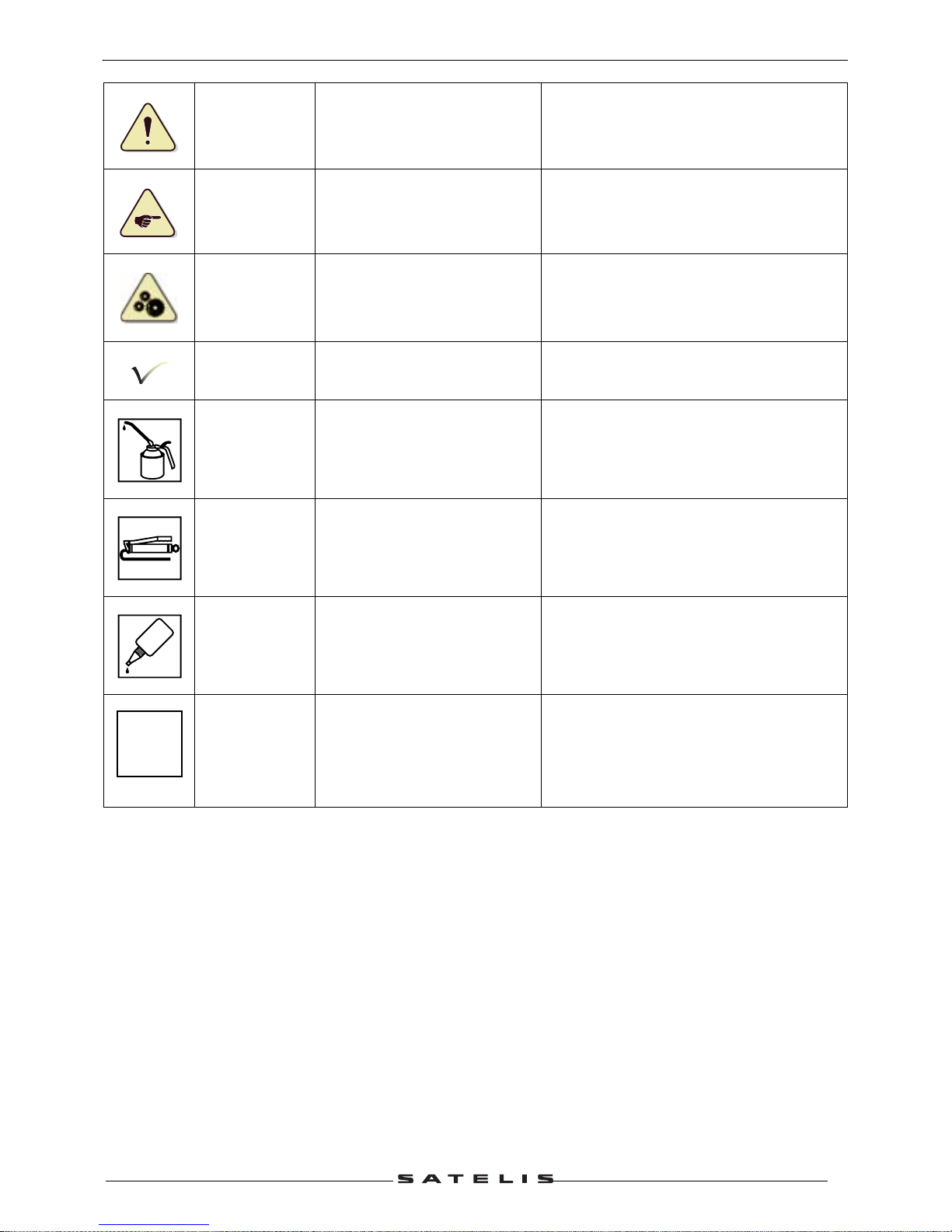
PRODUCTS DANGER SYMBOLS USED
Protection of individuals and of the environment. .
Möbius band Recyclable
Means that the product or the package
can be recycled. However, this does not
guarantee that the product will be recycled
Irritant
The product can irritate the
skin, eyes and repiratory
organs
Avoid contact with the skin and clothes.
Wear gloves, safety glasses and
appropriate clothes such as a cotton
overall. Do not breath fumes. If in contact,
wash thoroughly with water
Flammable The product is flammable
Keep it away from any flame or heat
source (barbecue, radiator, heating
device, etc.). Do not leave the product in
the sun
Corrosive
The product can damage living
tissues or other surfaces
Avoid contact with the skin and clothes.
Wear gloves, safety glasses and
appropriate clothes such as a cotton
overall. Do not breath fumes
Explosive
The product can explode under
certain circumstances (flame,
heat, impact, friction)
Avoid impacts, friction, sparks and heat
Hazardous to
the environment
The product affects fauna and
flora. Do not dump it in
garbage cans, sinks or nature
The ideal solution is to bring this product
to your nearest household waste recycling
centre
Toxic
The product can seriously
affect health if it is inhaled,
ingested or in contact with skin
Avoid direct contact with body even by
inhalation. If you fee l unwell, seek medical
advice immediately
Do not throw
away into a
garbage can
One of the product's
component is toxic and can be
hazardous to environment. F or
example: Used batteries
This symbol informs the consumer that the
used product shall not be thrown awa y into
a garbage can, but shall be brought back
to the merchant or dropped at a specific
collection point
Compulsory
gloves
Operation that can be
dangerous for people
People's saf ety can be seriously aff ected if
the recommendations are not fully
respected
PRODUCTS DANGER SYMBOLS USED
5
Reproduction or translation, even partial, is forbidden without the written consent of Peugeot Motocycles
People's safety
Operation that can be
dangerous for people
People's saf ety can be seriously aff ected if
the recommendations are not fully
respected
Important
Operation that can be
hazardous to the vehicle
Indicate the specific procedures that shall
be followed in order not to damage the
vehicle
Good operating
condition of the
vehicle
The operation must be carried
out in strict compliance with the
documents
Serious damage to the vehicle and in
certain cases a cancellation of the
warranty can be involved if the
recommendations are not fully respected
Note Operation that can be difficult
Indicate a note which gives key
information to make the procedure easier
Lubricate
Lubricate the parts to be
assembled
Indicate the specific procedures that shall
be followed in order not to damage the
vehicle
Grease
Grease the parts to be
assembled
Indicate the specific procedures that shall
be followed in order not to damage the
vehicle
Glue Glue the parts to be assembled
Indicate the specific procedures that shall
be followed in order not to damage the
vehicle
New part Use a new part
Indicate the specific procedures that shall
be followed in order not to damage the
vehicle
GLUE
N

CHARACTERISTICS
6
Reproduction or translation, even partial, is forbidden without the written consent of Peugeot Motocycles
CHARACTERISTICS
Engine
Capacities
400 cc 500 cc
Marking M564M M563M
Type
4-stroke single-cylinder
4 valves per cylinder with chain driven overhead camshaft
Cooling Liquid
Bore x stroke 85.8 x 69 mm 94 x 71 mm
Cubic capacity 398.9 cc 492.7 cc
Max. power output 24 kW at 7250 rpm 29 kW at 7500 rpm
Max. torque rating 5250 rpm
Compression ratio 10.6 bars
Lubrication Trochoidal pump
Transmission By 2 variable pulleys and V-type belt
Clutch Centrifugal automatic
Exhaust Catalytic
Starter motor Mitsuba 900 W
Spark plug
1 spark plug 2 spark plugs
NGK CR7EKB
Electrode gap
0.7-0.8 mm
Magneto flywheel Mitsuba 350 W
Fuel supply
Indirect electronic injection
Magneti-Marelli
Engine oil
1.7 l SAE 5W40.
Minimum grade: API SJ.
Relay box oil
0.25 l SAE 80W90.
Minimum grade: API GL4.
Coolant 1.4 LPeugeot coolant part number 754614
Fork oil 200 cc per tube (Esso Univis 46 or Agip HLift 46)
Fuel tank 13.2 L
CHARACTERISTICS
7
Reproduction or translation, even partial, is forbidden without the written consent of Peugeot Motocycles
Chassis
Dimensions and weight
Tyres
Chassis Double cradle out of high-resistance steel tube
Front suspension Hydraulic telescopic fork. Ø40 mm
Travel 110 mm
Rear suspension 2 adjustable combined spring hydraulic shock absorbers
Travel 90 mm
Overall length
2168 mm
Width at handlebar
769 mm
Height. (without rear-view
mirrors)
1140 mm
Wheelbase 1534 mm
Ground clearance
174 mm
Saddle height
784 mm
Unladen weight
218 kg.
Front wheel rim 14 inch aluminium alloy
Front tyre 120/70 - 14
Front tyre pressure 2.2 bars
Rear wheel rim 14 inch aluminium alloy
Rear tyre 150/70 - 14
Rear tyre pressure 2.4 bars
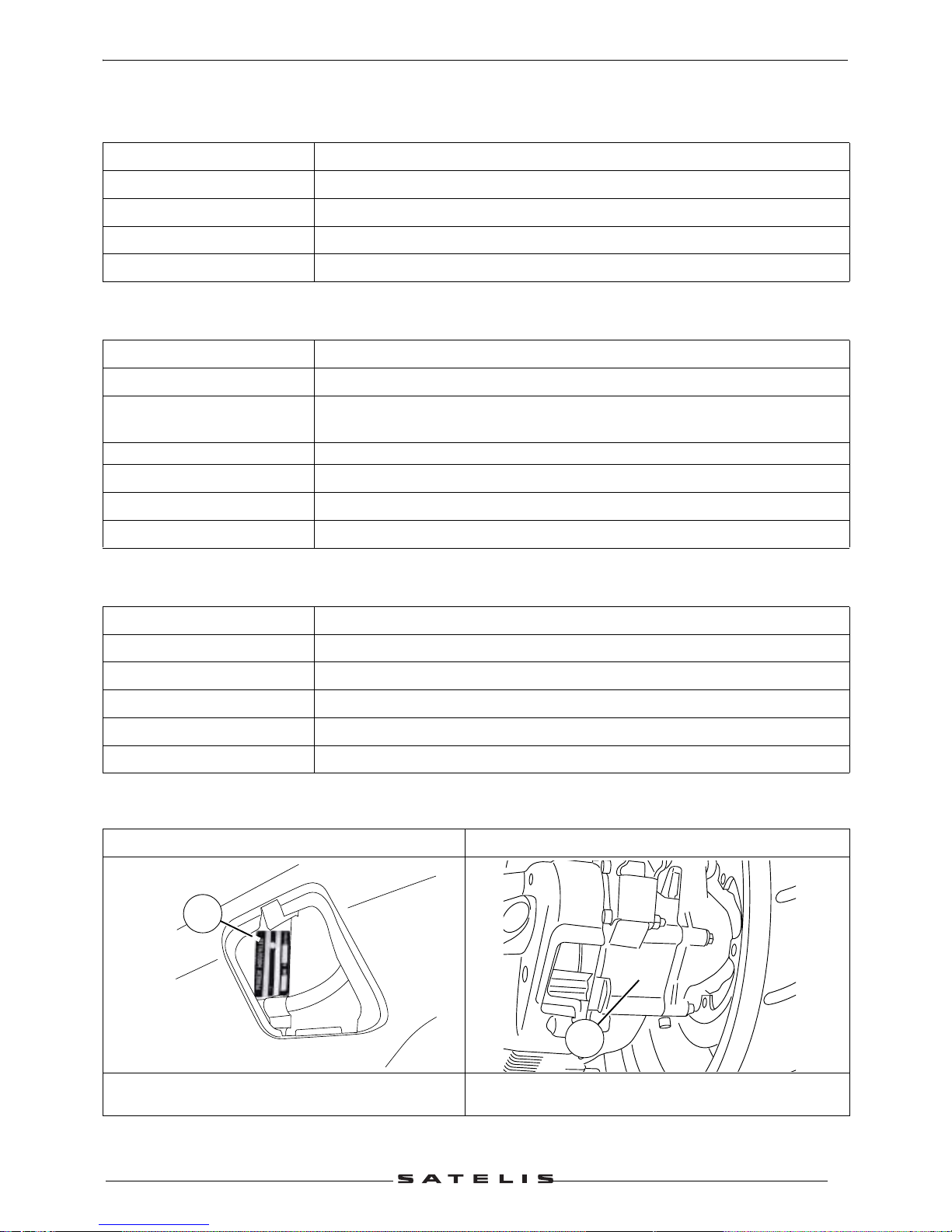
Chassis markings Engine marking
1. Manufacturer's plate. (Left side).
- VIN number of the RH side of the vehicle
2. Engine number
1
xxxxxxxxxx
M461M
2
SERVICE SCHEDULE AND COMMISSIONING
8
Reproduction or translation, even partial, is forbidden without the written consent of Peugeot Motocycles
SERVICE SCHEDULE AND COMMISSIONING
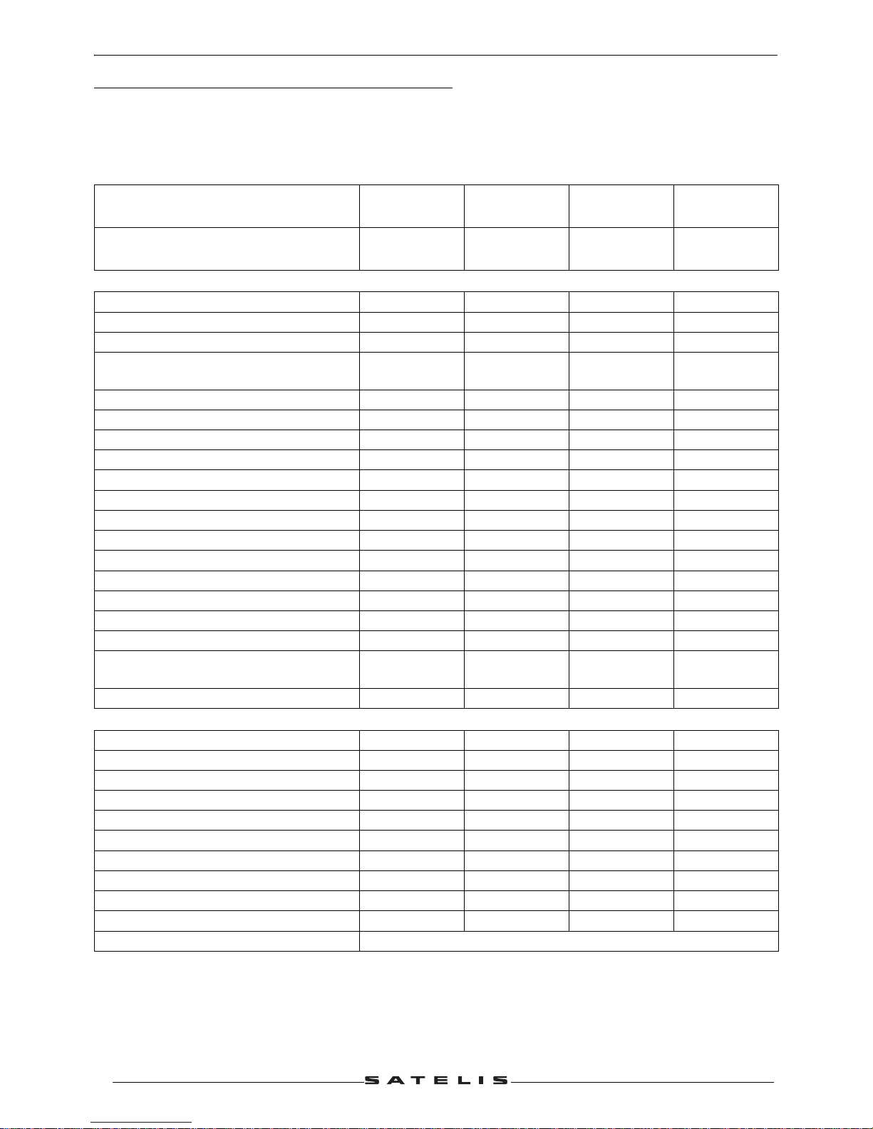
Heavy duty servicing is for vehicles used under "harsh" conditions: door-to-door deliveries, intensive
urban use (courier), short journeys with engine cold, dusty areas, ambient temperature over 30°C.
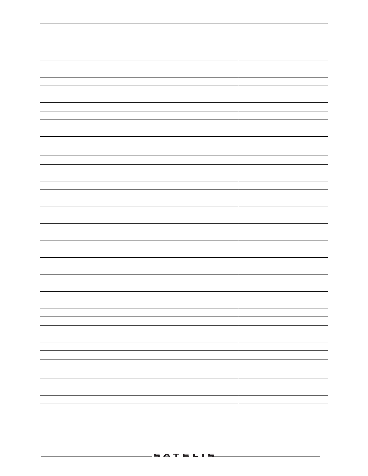
Service operations
1000 kms or
1 months
Every
5000 kms
Every
10000 kms
Every
20000 kms
Heavy duty servicing 500 kms
Every
2500 kms
Every
5000 kms
Every
10000 kms
Check
Throttle cable play C C C C
Steering column play C C C C
Operation of electrical equipment C C C C
Condition of front and rear brake
hydraulic controls
CCCC
Condition of petrol pipes C C C C
Condition of oil pipes C C C C
Tyre pressures C C C C
Tyre condition, pressure and wear C C C
Condition of the front suspension C C C C
Condition of the rear suspension C C C C
Brake fluid level C C C C
Battery electrolyte level* C C C C
Coolant level C C C C
Engine oil level C
Valve clearances C
Transmission air filter N N
Intake silencer drain N N N N
Tightening the engine mounting and
linkrod
CCC
Tightness of nuts and bolts C C C C
Change
Spark plug R R
Inlet silencer/air filter R R
Front brake pads #. C C C
Rear brake pads #. C C C
Drive pulley bearings and guides #. C C
Transmission belt R R
Belt anti-flapping roller #. C C
Engine oil (+ clean strainer) R R R
Engine oil filter R R R
Relay box oil R C C
Brake fluid and coolant Once every 2 years
SERVICE SCHEDULE AND COMMISSIONING
9
Reproduction or translation, even partial, is forbidden without the written consent of Peugeot Motocycles
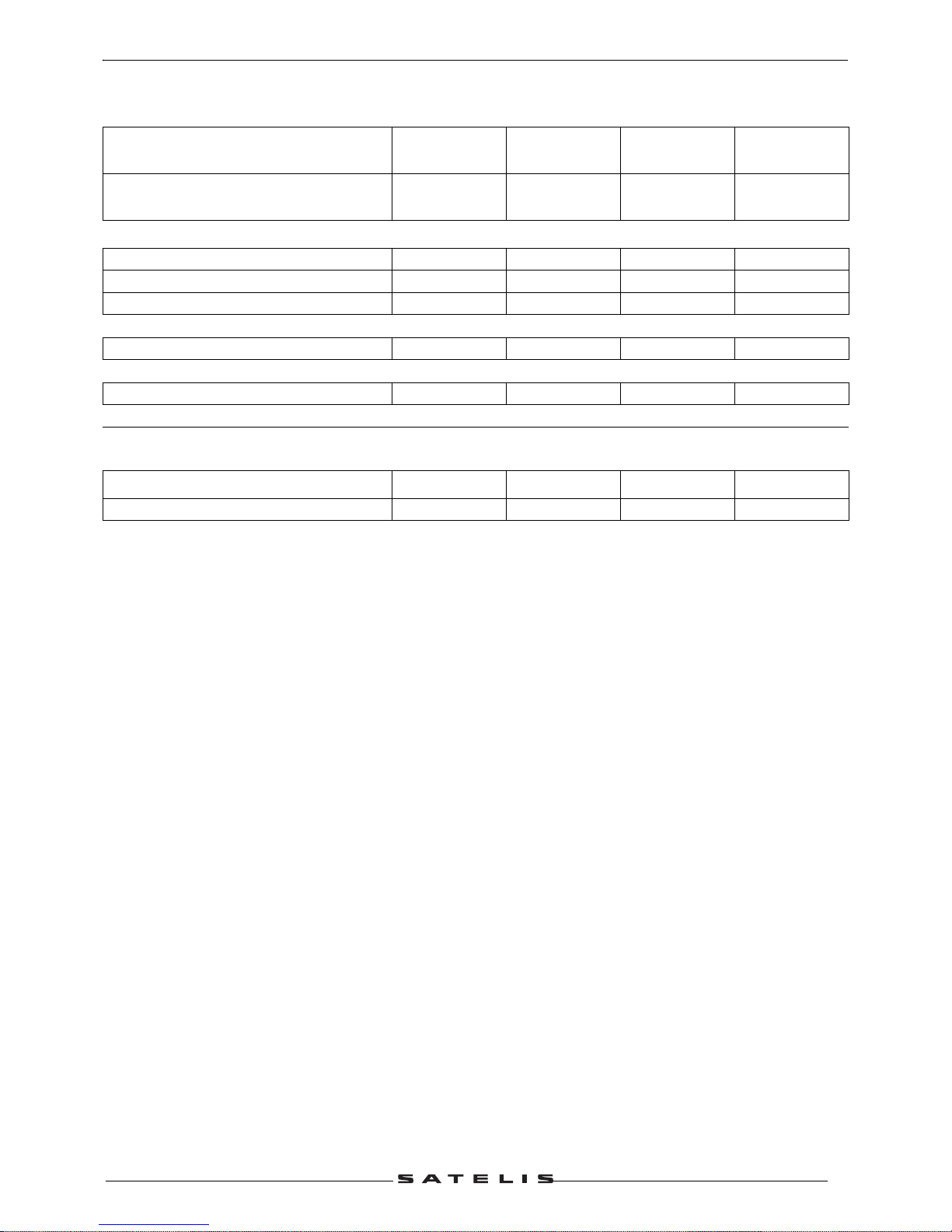
C: Check.
N: Clean.
R: Change.
G: Check and lubricate.
* Depending on equipment.
# Change if necessary.
Service operations
1000 kms or
1 months
Every
5000 kms
Every
10000 kms
Every
20000 kms
Heavy duty servicing 500 kms
Every
2500 kms
Every
5000 kms
Every
10000 kms
Check and lubricate
Drive pulley/Movable face C C
Driven pulley: Movable face C C
Driven pulley caged needle bearing G G
Reading the ECU fault codes
Injection and ABS/MBS* system C C C C
Test machine
On road (at least 2 km) C C C C
Time required for
maintenance
Code 9100 9300 9400 9600
Time required for maintenance 1.0 0.8 2.4 3.5

SERVICE SCHEDULE AND COMMISSIONING
10
Reproduction or translation, even partial, is forbidden without the written consent of Peugeot Motocycles
Battery preparation (Except battery without maintenance)*
Remove the battery.
Remove the 6 filler caps and the vent plug.
Fill all the battery cells with electrolyte to the upper level shown on the battery "UPPER LEVEL".
Electrolyte: (35 sulfuric acid = 1.28g/cm
3
).1 litre can P/N 752740. 5 litre can P/N 752741.
Leave the battery to stand for around half an hour.
Top up if necessary.
Charge the battery for at least 2 hours with a current of 1.4 A.
Refit the battery and connect the vapour vent pipe.
Connect the red wire lug to the battery's + terminal, and the green wire lug to the battery's - terminal.
Then, the battery level should be topped up if necessary, after fully charging, using distilled water only.
Checks before handing over to the customer
Check the wheel nuts are tight.
Check nuts and bolts are tight.
Check brake adjustment and efficiency.
Check the tyre pressures cold.
Check operation of the lights, flashers, horn, and brake light.
Check the different warning lights work.
Carry out a road test.
* Depending on equipment.
SPECIAL IMPORTANT POINTS
11
Reproduction or translation, even partial, is forbidden without the written consent of Peugeot Motocycles
SPECIAL IMPORTANT POINTS
Oil and fuel
This engine is designed to run on 95 or 98 unleaded fuel only.
Fuel pipes must absolutely be changed if there are any signs of wear, cracks, etc.
The clips are specific, they must always be changed each time they are removed and replaced
with new genuine parts clips.
Petrol is highly inflammable, do not smoke in the working area and avoid pr oximity to flames or
sparks.
Before carrying out any work, leave the engine to cool for at least 2 hours.
Starting up after overhauling the engine
When starting the engine hot or cold do not accelerate.
Check the coolant level in the header tank.
After road-testing the machine, check there are no fault codes left in the ECUs (using the diagnostic
tool).
Electricity
All components of the electrical system are powered with 12 volts DC.
The battery must not be disconnected while the engine is running and the voltage must be at least
7 volts for the ECU to function and enable engine starting.
Special features
An immobiliser built in the ECU provides the antitheft function by means of a transponder.
The ECU has a diagnostic function which via the instrument cluster LED or the diagnostic tool, enables
reading of the faults in the memory.

TIGHTENING TORQUES
12
Reproduction or translation, even partial, is forbidden without the written consent of Peugeot Motocycles
TIGHTENING TORQUES
Engine part
Drive pulley 17 m.daN
Driven pulley 9.6 m.daN
Clutch plate and shoes 7 m.daN
Belt anti-flapping roller 1.8 m.daN
Transmission cover;
• 6 mm diameter screw
• 8 mm diameter screw
1.2 m.daN
2.4 m.daN
Relay box cover 2.5 m.daN
Relay box drain plug 1.5 m.daN
Flywheel magneto cover 1.2 m.daN
Stator 1m.daN
Engine speed sensor 0.5 m.daN
Rotor 12 m.daN
Freewheel 1.4 m.daN
Starter motor 1.2 m.daN
Automatic tensioner 1.2 m.daN
Automatic tensioner plug 0.5 m.daN
Spark plug 1.2 m.daN
Decompressor valve balance weight 0.8 m.daN
Decompressor valve housing 3.2 m.daN
Chain tensioner 1.2 m.daN
Camshaft stop plat 0.5 m.daN
Cylinder head. (Guide pins) Procedure
Cylinder head bolts and nuts 1.2 m.daN
Cylinder head cover 0.8 m.daN
Inlet manifold 1.2 m.daN
Engine temperature sensor 1.1 m.daN
Injection ECU 1.2 m.daN
Injection rail 0.3 m.daN
Oil pressure switch 1.2 m.daN
Oil pump 0.6 m.daN
Oil filter 1.4 m.daN
Oil pump cover 0.9 m.daN
Crankcase 1.2 m.daN
Conrod and crankshaft assembly gear 1.1 m.daN
Balancing shaft 2.8 m.daN
Engine drain plug 2.5 m.daN
Water pump cap 0.4 m.daN
Water pump impeller 0.5 m.daN
Cooling system bleeder screw 0.3 m.daN
TIGHTENING TORQUES
13
Reproduction or translation, even partial, is forbidden without the written consent of Peugeot Motocycles
Body panels
Cycle part.
Standard
Front mudguard 0.8 to 1.2 m.daN
Handlebar cover 0.2 to 0.4 m.daN
Front shield panels 0.2 to 0.4 m.daN
Rear shield 0.2 to 0.4 m.daN
Bottom panel 0.2 to 0.4 m.daN
Floor panel 0.4 to 0.6 m.daN
Saddle storage compartment 0.8 to 1.2 m.daN
Rear panels 0.2 to 0.4 m.daN
Grab handle 2 to 2.5 m.daN
Rear mudguard 0.4 to 0.6 m.daN
Front wheel spindle 6.5 m.daN
Rear wheel bolt 2.5 m.daN
Rear wheel spindle nut 13.5 m.daN
Linkrod to engine pivot 8 m.daN
Linkrod to frame pivot 8 m.daN
Linkrod connecting pin 8 m.daN
Linkage torque arms 3.8 m.daN
Shock absorber top mount 4.5 m.daN
Shock absorber bottom mount 4.5 m.daN
Exhaust to cylinder head mounting nut 2.2 m.daN
Exhaust to casing mounting bolt 2.2 m.daN
Exhaust system strap 1.8 m.daN
Exhaust clamp 1.8 m.daN
Centre stand holder 2.2 m.daN
Suspension arm 2.8 m.daN
Lambda sensor 4.5 m.daN
Upper cone (in 2 operations) 4/2.2 m.daN
Upper cone locknut Hand tightened
Steering locknut 7.5 m.daN
Front brake caliper 2.5 m.daN
Rear brake caliper 2.5 m.daN
Front brake disc 3 m.daN
Rear brake disc 3 m.daN
Handle bar 4 m.daN
Nut and bolt 5 mm diameter 0.6 m.daN
Nut and bolt 6 mm diameter 1 m.daN
Nut and bolt 8 mm diameter 2.2 m.daN
Nut and bolt 10 mm diameter 3.5 m.daN
Nut and bolt 12 mm diameter 5.5 m.daN
SPECIAL TOOLS
14
Reproduction or translation, even partial, is forbidden without the written consent of Peugeot Motocycles
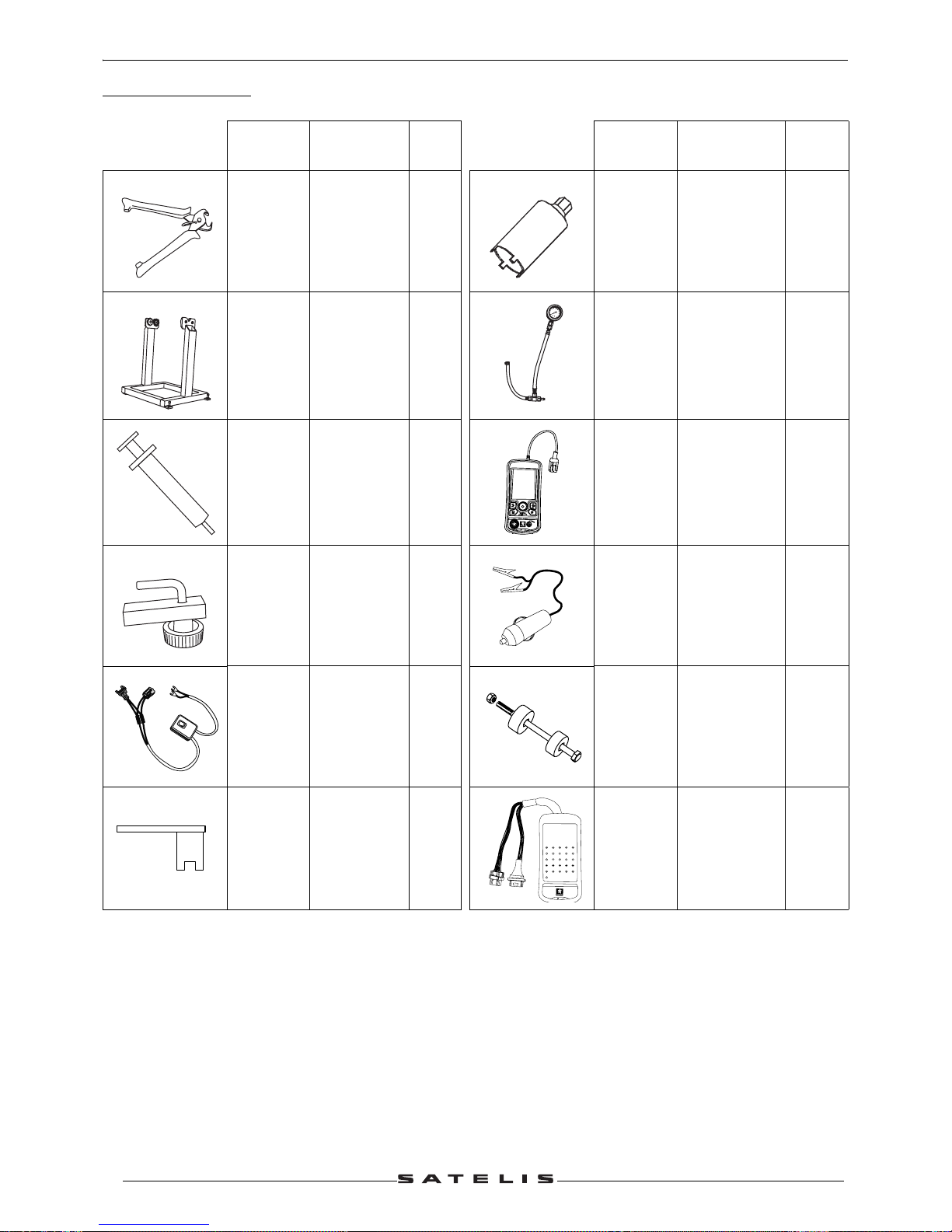
SPECIAL TOOLS
(*) New or modified tool
Tool N° Designation
Used
with
Tool N° Designation
Used
with
750539
Tie-wrap
pliers
757860 Steering tool
754278
Balance
support with
pins Ø15 and
Ø17 mm
757877
Pressure
gauge
754306
Bleed
syringe
758358 TEP 2005
755996 Hose clamp 758585
Power supply
cable tool
756017
Fuel injector
power supply
harness
758810
Steeing head
cup
installation
tool
756715
(*)
Tank gauge
spanner
758924
24 way
terminal block
0
6
8
1
0
2
4
b
a
r
OK
TEP 2005
by
xxo
test
1
24122311221021
9208197186
17516
151413
26
25
432
BM 2005
b
y
xxo
t
e
s
t

SPECIAL TOOLS
15
Reproduction or translation, even partial, is forbidden without the written consent of Peugeot Motocycles
Standard tools
Oil filter notched cap
wrench.
Type: Facom D155
Automatic resetting type
torque wrench.
10 to 50 Nm
Type: Facom J.208A50
Automatic resetting type
torque wrench.
5 to 25 Nm
Type: Facom R.306A25
Automatic resetting type
torque wrench.
40 to 200 Nm
Type: Facom S.208A200
ELECTRONIC INSTRUMENT FUNCTIONING PRINCIPLE
16
Reproduction or translation, even partial, is forbidden without the written consent of Peugeot Motocycles
ELECTRONIC INSTRUMENT FUNCTIONING PRINCIPLE
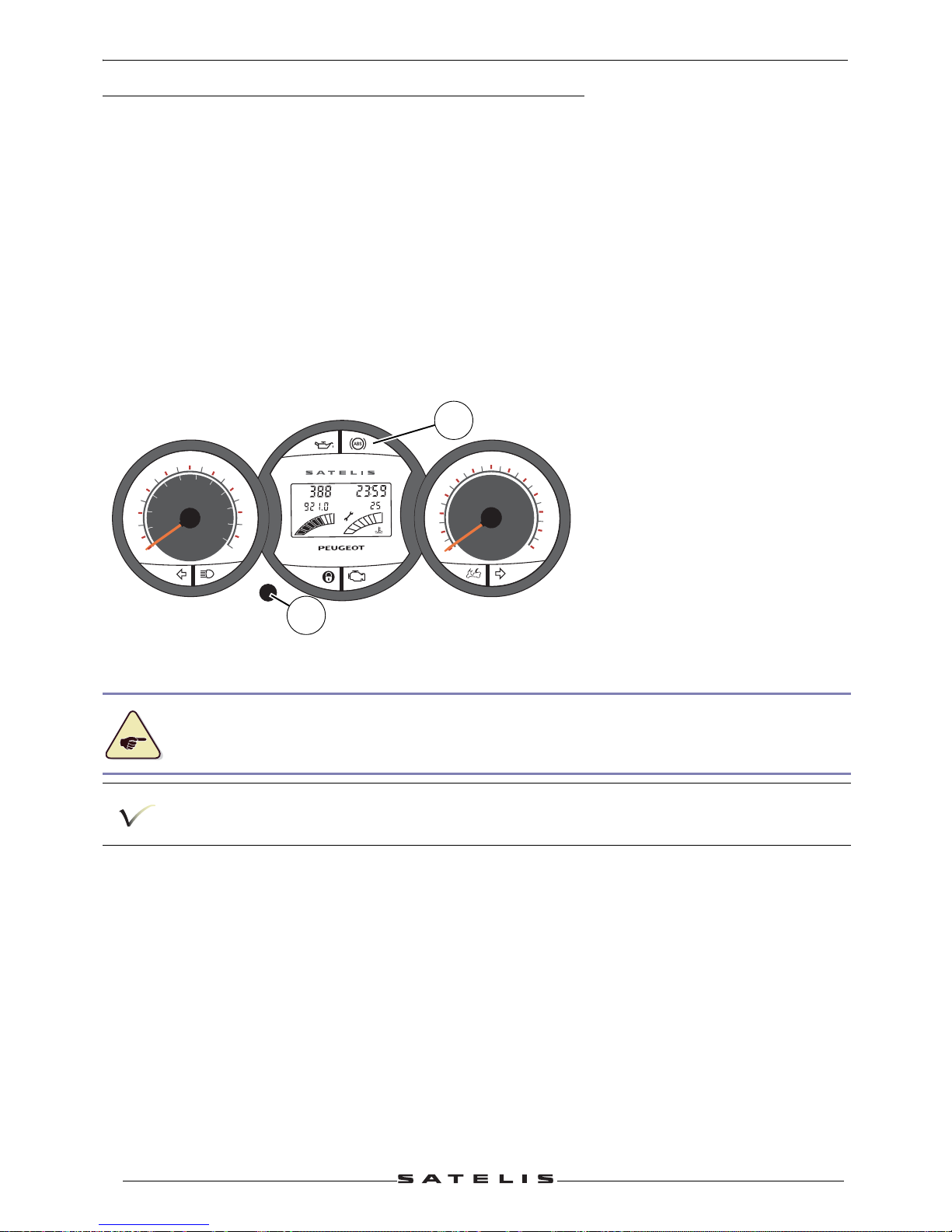
Functions of the instrument panel
Initializing the system
The instrument panel initializes itself every time the ignition is switched on:
- All warning lights are switched on.
- All elements of the multifunctional display are activated.
- The two hands (speedometer and revolution counter) move simultaneously from the minimum to
the maximum and back.
If this is not the case, switch the ignition off, disconnect and re-connect the battery.
After initializing, the low oil, stoplight or ABS, injection diagnosis indicator lights remain on.
- Speedometer.
- Revolution counter.
- Tripmeter.
- Daily odometer.
-Digital clock.
- Fuel gauge.
- Outside temperature gauge.
- Engine temperature gauge.
- Battery voltage fault.
- Maintenance indicator.
- Flasher unit.
Instrument panel indicator lamps:
• Oil pressure.
• ABS/MBS or STOP
• Left direction indicator.
• High beam.
• Immobiliser state.
• Diagnosis of the ignition system.
• Opening the storage compartment.
• Right direction indicator.
(A) Control button.
Two versions are available:
1. Basic version featuring
a STOP indicator light (B).
2. ABS/MBS version
featuring an ABS indicator
light (B)
When preparing the vehicle, switch off the ignition and connect the battery. The system
initializes itself when connecting the battery.
The battery must never be connected or disconnected when the ignition is switched on.
ABS
km
°C
C
F
E
H
Trip
EFI
km/h
mph
70
10
20
30
40
50
60
80
90
100
110
10
0
30
50
70
90
110
130
150
170
X1000 r/min
0
1
2
3
4
5
6
7
8
9
10
11
12
B
A
ELECTRONIC INSTRUMENT FUNCTIONING PRINCIPLE
17
Reproduction or translation, even partial, is forbidden without the written consent of Peugeot Motocycles
Analog functions (hands)
Speedometer.
Double-scale indication, kilometres/miles.
Vehicle without ABS/MBS: The signal is supplied by the speed sensor mounted on the front wheel.
Vehicle with ABS/MBS: The signal is sent by the ABS/MBS ECU.
Revolution counter.
Vehicle with Magneti Marelli ECU: 2 pulses per engine revolution.
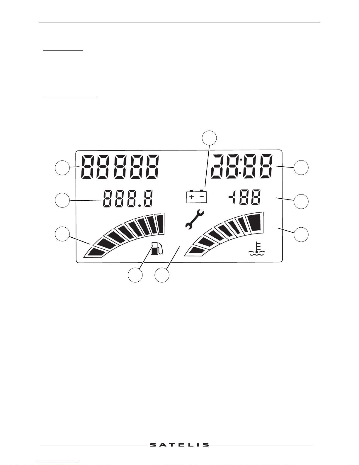
Numeric functions (multifunctional display)
1. The tripmeter.
2. Daily odometer.
3. Fuel gauge.
4. Digital clock.
5. Outside temperature gauge.
6. Engine temperature gauge.
7. Battery voltage fault.
8. Maintenance indicator.
9. Empty tank indicator light.
km
Miles
°C
°F
C
F
E
H
Trip
1
2
6
3
89
7
4
5
ELECTRONIC INSTRUMENT FUNCTIONING PRINCIPLE
18
Reproduction or translation, even partial, is forbidden without the written consent of Peugeot Motocycles
Tripmeter.
The tripmeter displays and stores the number of kilometres travelled by the vehicle.
Changing the distance unit (km or miles) is as follows
- The ignition is switched off, press the control button while switching on the ignition, the distance unit
will flash.
- Select the unit by briefly pressing the control button, the distance unit changes from "km" to "miles"
or inversely.
- Switch off ignition to confirm.
Daily odometer.
The tripmeter displays and stores the number of kilometers travelled during a given period.
The daily odometer uses the same unit of measurement as the tripmeter.
Resetting the daily odometer:
- Press the control button (several times briefly) until the figures of the daily odometer flash.
- Pressing the control button for more than 3 s allows you to reset the daily odometer.
Fuel gauge.
In the fuel reserve position, the two last segments are lit and flash.
When the fuel tank is empty, all segments are off and the pump flashes.
Fuel gauge self-diagnostic
All segments flash if the fuel gauge or its wiring is faulty. Open circuit (wire cut).
The machine total kilometres remains in the memory when the battery is disconnected.
If the distance unit is kilometres, the outside temperature is displayed in °C.
If the distance unit is miles, the outside temperature is displayed in °F.
ELECTRONIC INSTRUMENT FUNCTIONING PRINCIPLE
19
Reproduction or translation, even partial, is forbidden without the written consent of Peugeot Motocycles
Digital clock.
Time setting:
Press the control button (several times briefly) until the figures of the clock flash.
Pressing the control button for more than 3 s make the the time characters flash.
Set the time by successive pushes on the control button.
Pressing the control button for more than 3 s will make the first character of the minutes flash.
Set the time by successive pushes on the control button.
Pressing the control button for more than 3 s will make the second characters of the minutes flash.
Set the time by successive pushes on the control button.
Pressing the control button for more than 3 s will allow you to confirm the time.
Outside temperature gauge.
Engine temperature gauge.
Vehicle with Magneti Marelli ECU: the engine temperature sensor controls the temperature gauge.
When the engine temperature is too high, all segments are switched on and the last flashes.
Temperature alarm. On the basic instrument panel, the stop warning light is on.
If the temperature information does not reach the instrument panel, all segments flash. Open circuit
(wire cut).
Battery voltage fault.
The battery charge warning light flashes if the battery voltage goes below 11.2 volts and it stops
flashing when the voltage passes again above 11.7 volts.
The battery charge warning light flashes and the stop warning light comes on (only basic instrument
panel version) when the battery voltage is below 16 volts.
Maintenance indicator.
Maintenance function:
The maintenance indicator goes on 5000 kms after the last reset.
Maintenance reset:
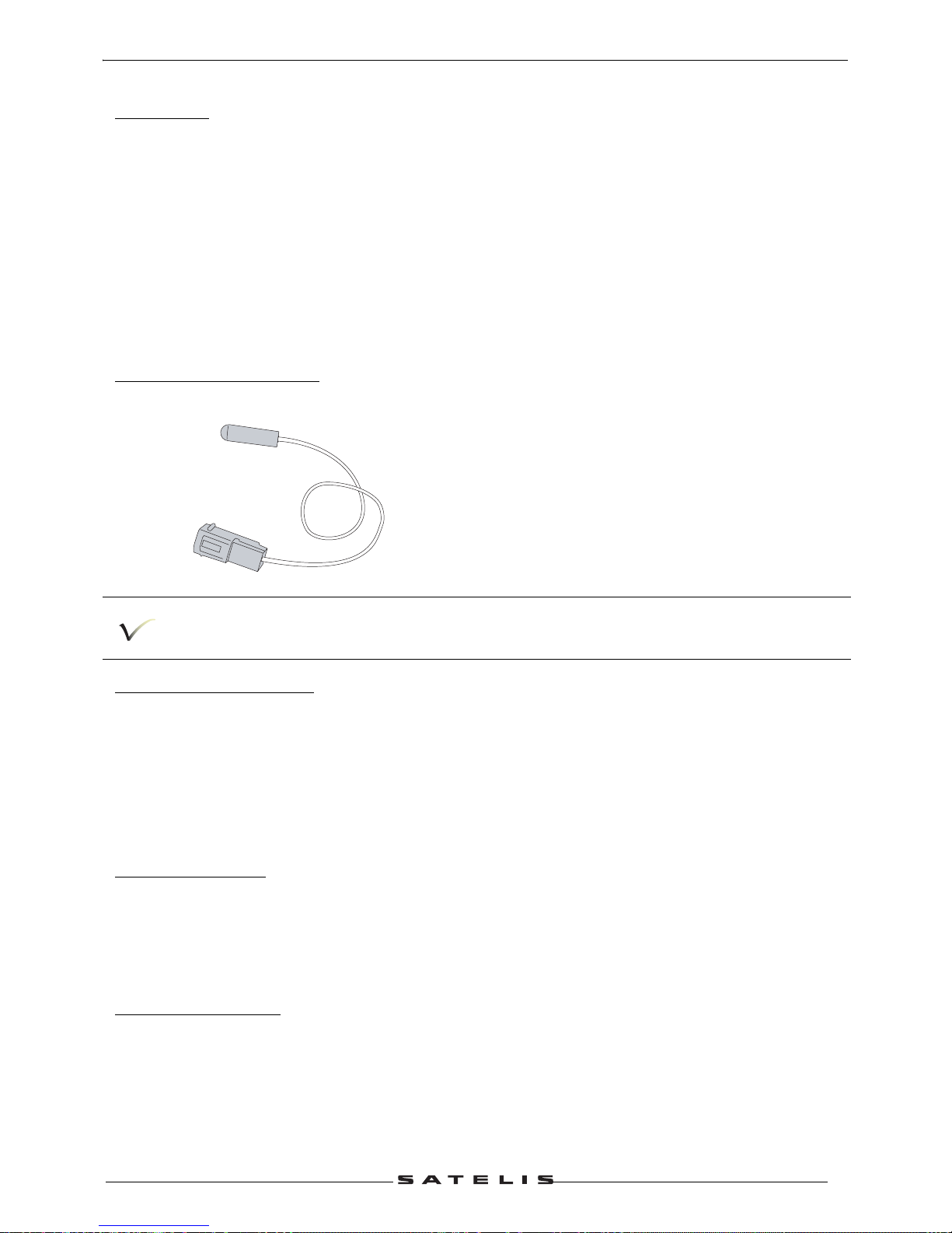
Outside temperature sensor.
If the distance unit is kilometres, the outside temperature is displayed in °C.
If the distance unit is miles, the outside temperature is displayed in °F.
ELECTRONIC INSTRUMENT FUNCTIONING PRINCIPLE
20
Reproduction or translation, even partial, is forbidden without the written consent of Peugeot Motocycles
- The ignition is switched off, press the control button while switching on the ignition, the distance unit
will flash.
- Pressing the control button for more than 5s allows you to reset the maintenance indicator, and the
"key" icon will go off.
Additional functions
Flasher unit.
The instrument panel is equipped with one flasher unit per side.
A buzzer reminds the driver of the direction indicators.
For the hazard warning lights, both flasher units operate.
The flasher unit is protected against accidental short-circuits.
The ignition must be turned on again to activate the hazard warning lights function.
The hazard warning lights can only operate with the ignition off if they were turned on before switching
off the ignition.
The hazard warning lights are switched off automatically 1 hour after the ignition was switched off, to
perserve the battery.
Instrument panel indicator lamps.
Basic version:
To allow a better warning of the driver, the stop warning light will come on besides the spe cific alarm
warning light in the following cases:
- Oil pressure fault.
- Engine temperature fault.
- Battery overvoltage faulr.
Lighting control.
The instrument panel controls the lighting of the vehicle. When the ignition is switched on, the parking
lights go on. The headlight goes on when the engine is started (Depending on the position of the dip
beam/high beam switch).
The headlight remains on as long as the vehicle runs, even if the engine stalled, and remains on 7 s
after the vehicle stopped running.
The headlight remains on for 3 s after the ignition was switched off, when the wehicle is stopped.
ABS/MBS system control.
The ABS/MBS ECU remains powered as long as the vehicle runs, even if the engine stalled.
Incident.
Revolution counter and speedometer hands are not synchronized when switching the ignition on.
When a flasher bulb has failed the repeater light an d the other f lasher light f lash more quickly t o
alert the rider of a failure.
In the high beam position, both dip beam and high beam are on simultaneously.

ELECTRONIC INSTRUMENT FUNCTIONING PRINCIPLE
21
Reproduction or translation, even partial, is forbidden without the written consent of Peugeot Motocycles
- Turn off the ignition.
- Disconnect and re-connect the battery.
The engine speed displayed is the double of the actual speed. Faulty detection of the measuring
system.
Vehicle with Magneti Marelli system. Temperature sensor circuit not detected.
- Check the engine temperature sensor circuit.
- Turn off the ignition.
- Disconnect and re-connect the battery.
ELECTRICITY
22
Reproduction or translation, even partial, is forbidden without the written consent of Peugeot Motocycles
ELECTRICITY
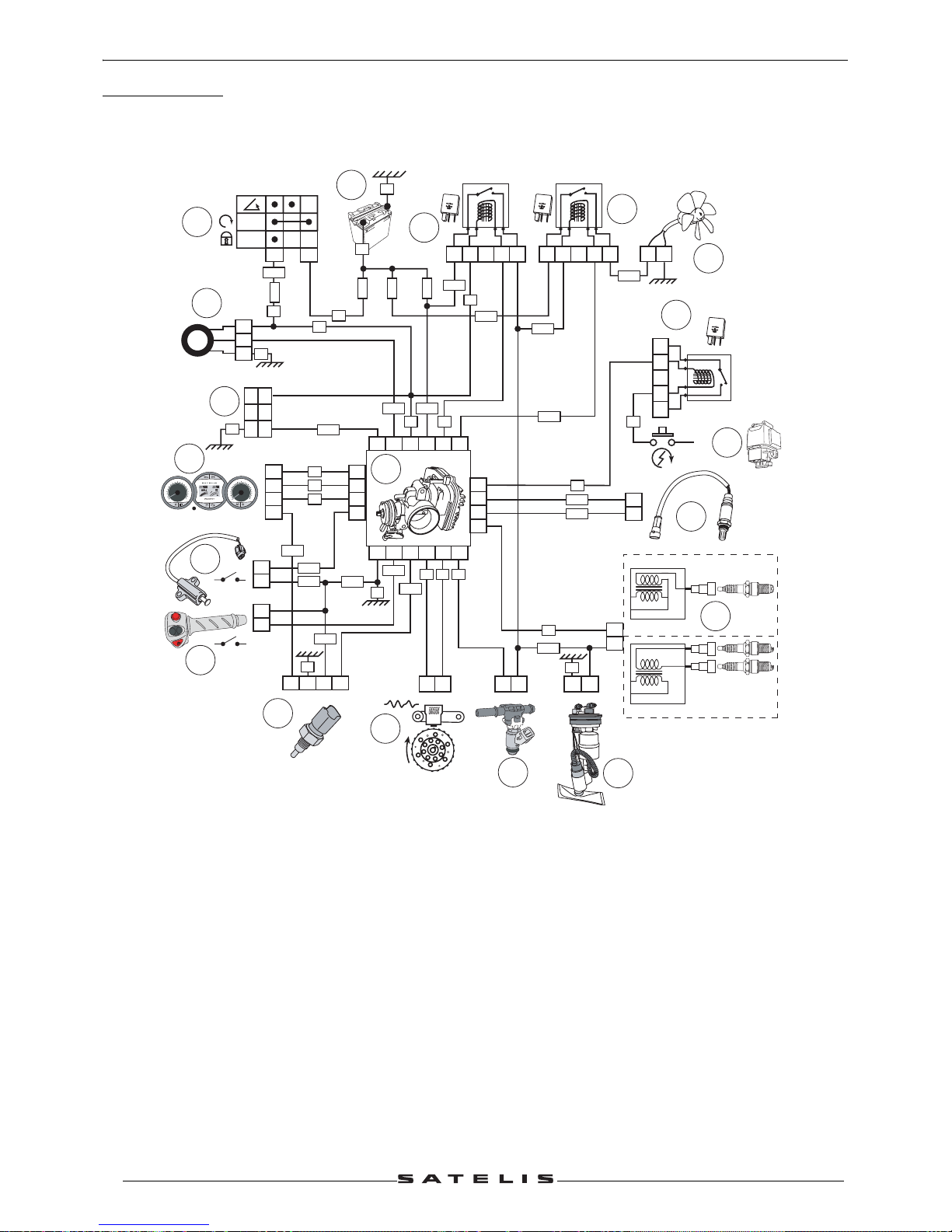
4 stroke indirect injection system functional diagram
1. Injection ECU.
2. Engine speed and position sensor.
3. Petrol injector.
4. Fuel pump.
5. Ignition coil.
6. Lambda sensor.
7. Starter motor switch.
8. Starter motor relay.
9. Cooling fan.
10. Fan relay.
11. Injection relay.
12. Battery.
13. Ignition switch.
14. Transponder antenna.
15. Diagnostic plug.
16. Instrument panel.
17. Kickstand switch.
18. Emergency stop switch.
19. Engine temperature sensor.
1
2
V
2
5
A
21345
1
2
V
2
5
A
12345
2
1
3
4
5
1
2
6
3
OFF
ON
8
14
2
1
-
U
P
P
E
R
L
E
V
E
L
L
O
W
E
R
L
E
V
E
L
VE
B1A1
A3
VE
6
5
4
3
2
19
16
15
14
13
12
11
10
9
8
7
2
1
21
22
11
4
15 1413926 12
2
1
17
18
82420716 5 6
1
1
2
1
2
3
2
1
x
x
1
2
30A
F1
7,5A
F6
15 A
F2
15A
F4
VE
VE
JN
BCNR
NR
NR
RG
RG
VI
VE-NR
RG-BA
BA-BE
VE-NR
BE-NR
BA-VE
VI-BA
BE-NR
GR-RG
RG-NR
VI-NR
VE-NR
GR-RGMR-BA
BA-NR
12
+
VC
BE
BA
VE
VE
RG MR OR
VI
NR
ABS
k
m
°C
C
F
E
H
T
r
i
p
EFI
km/h
mph
7
0
10
2
0
3
0
4
0
5
0
60
8
0
90
100
110
1
0
0
30
50
7
0
90
110
1
3
0
1
50
17
0
X1000 r/min
0
1
2
3
4
5
6
7
8
9
10
11
12
GR-VE
GR-VE
GR-VE
GR-VE
R
R
R
400cc
500cc
17
18
0
1
0
1
1
2
V
-
2
5A
ELECTRICITY
23
Reproduction or translation, even partial, is forbidden without the written consent of Peugeot Motocycles
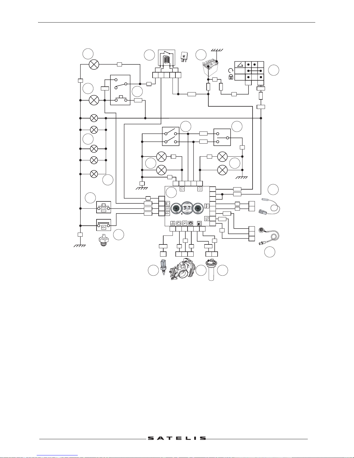
Schematic diagram of the instrument panel and of the lighting
1. Instrument panel.
2. Battery.
3. Ignition switch.
4. Immobilizer.
5. Injection ECU.
6. Fuel gauge.
7. Speed sensor.
8. Outside temperature sensor.
9. Oil pressure switch.
10.Saddle opening contact switch.
11.Lighting relay.
12.Dip beam.
13.High beam.
14.Dip switch (main/low headlight).
15."Side light" bulbs.
16.Number plate light.
17.Direction indicator switch.
18.Hazard warning lights switch.
19.RH direction indicators.
20.LH direction indicators.
-
U
P
P
E
R
LE
V
E
L
L
O
W
E
R
LE
V
E
L
3
6
OFF
ON
11 20122223
15
24
17
10
0
1
2
3
4
5
6
7
8
9
1
0
11
12
12
V
2
5
A
21543
30A
F1
15A
F4
15A
F5
4 514218
172 1
3
1
2
EFI
16
19
6
7
9
26
21
18
H7 12V-55W
H7 12V-55W
12V-5W
12V-5W
12V-5W
12V-10W12V-10W
VE
VE
JN
MFVC
BE BA
GR
RS
RS
BCOR
RG
RG
VE
VE
VE
BA
MR
GR-NR
GR-BE
OR-BA
GR-NR
RG-NR
BA-BE
GR-NR
GR-BE
VE-NR
MR-BA
RS-BA
VE-BE
JN-BE
JN-BA
JN-BE
ABS
km
°
C
C
F
E
H
Tri
p
EFI
km/h
mph
7
0
1
0
20
3
0
4
0
5
0
6
0
80
90
1
0
0
110
10
0
3
0
50
7
0
90
110
1
3
0
1
5
0
1
70
X1000 r/min
0
1
2
3
4
5
6
7
8
9
1
0
1
1
1
2
RG-BA
9
5
7
64
15
17
8
10
11
13
18
1920
14
3
16
2
1
12

ELECTRICITY
24
Reproduction or translation, even partial, is forbidden without the written consent of Peugeot Motocycles
ABS/MBS system schematic diagram
1. Pressure control unit.
2. Speed sensor and pulse wheel.
3. Battery.
4. Ignition switch.
5. Power supply relay.
6. ABS/MBS relay.
7. ABS diode.
8. Starter motor switch.
9. Starter motor relay.
10.Injection ECU.
11.Diagnostic plug.
12.Instrument panel (diagnostic lamp,
machine speed).
7,5A
30A
START
PIN
VI
VI
VI
VE
BE/NR
BE/NR
BE/NR
GR/NR
RG/NR
MR/BA
JN/BA
JN/VE
VE
GR
BA
OR
JN
RG
VE
RG
RG
RG
BE
RG
VE
VE
A3
A2
A1 B1
B3
23911
3
14
5
17
19
21
25
20
13101
-
U
P
P
E
R
L
E
V
E
L
L
O
W
E
R
L
E
V
E
L
1
2
V
-
2
5
A
12345
1
2
V
2
5
A
12345
1
2
V
- 25
A
12345
6
3
OFF
ON
24
ABS
km
°
C
C
F
E
H
Tri
p
EFI
km/h
mph
70
10
20
30
40
5
0
60
80
9
0
1
0
0
1
1
0
10
0
30
50
70
90
1
10
130
150
1
7
0
X1000 r/min
0
1
2
3
4
5
6
7
8
9
10
11
12
24132623
12
5 6
7
8
10
9
11
3
4
2
1
 Loading...