

PEUGEOT MOTOR ENGINE Workshop Manual

WORKSHOP
MANUAL
MOTOR
ENGINE
SALES DIVISION
NETWORK TECHNICAL INFORMATION
CONTENTS
Page: 4
Reproduction or translation, even partial, forbidden without the written consent of Peugeot Motocycles
CHARACTERISTICS......................................................................................................................... 5
Engine markings............................................................................................................................................. 5
TIGHTENING TORQUES................................................................................................................. 5
SPECIAL TOOLS ............................................................................................................................... 6
IDENTIFICATION ............................................................................................................................. 7
Differences between the 3 types of assembly ................................................................................................ 7
DISASSEMBLY................................................................................................................................... 8
Fitting the engine to the support and adapter ................................................................................................. 8
To remove the drive pulley - types 1 and 2.................................................................................................... 8
To remove the governor - type 3.................................................................................................................... 9
To remove the clutch pulley assembly........................................................................................................... 9
To remove the magneto flywheel................................................................................................................. 11
To remove the coil assembly and the stator ................................................................................................. 11
To remove the coil assembly plate............................................................................................................... 12
To remove the cylinder head and cylinder/piston ........................................................................................ 13
To remove the inlet manifold and valve....................................................................................................... 13
Opening the casings...................................................................................................................................... 14
To remove the crank assembly..................................................................................................................... 15
To remove the bearings and seals................................................................................................................. 16
RE-ASSEMBLY................................................................................................................................. 17
To fit the bearing and seal in the LH casing................................................................................................. 17
To fit the bearing and seal in the RH casing ................................................................................................ 19
To fit the crank assembly in the LH casing.................................................................................................. 20
Assembling the casings ................................................................................................................................ 21
To assemble the engine bottom end and engine mount................................................................................ 22
To fit the valve and inlet manifold ............................................................................................................... 23
To fit the piston ............................................................................................................................................ 23
To fit the cylinder ......................................................................................................................................... 24
To fit the cylinder head ................................................................................................................................ 24
Type 1 - drive pulley without governor, without kickstart ............................................................ 26
Fitting the non-governor drive pulley (type 1)............................................................................................. 26
Type 2 - drive pulley with governor, without kickstart.................................................................. 28
Fitting the with-governor drive pulley (type 2)............................................................................................ 28
Type 3 - drive pulley with governor, with kickstart ....................................................................... 30
To fit the governor (type 3) .......................................................................................................................... 30
To fit the magneto flywheel ......................................................................................................................... 31
To remove the coil assembly and the stator ................................................................................................. 31
MISCELLANEOUS OPERATIONS ............................................................................................... 33
Drive pulley assembly .................................................................................................................................. 33
Clutch adjustment (with and without governor) types 1 and 2 .................................................................... 34
Changing the starting jaws (with and without governor) types 1 and 2....................................................... 35
To assemble the governor - type 2 ............................................................................................................... 35
Drive pulley assembly .................................................................................................................................. 37
To change clutch shoes................................................................................................................................. 37
To remove the drive pulley sprocket............................................................................................................ 37
To remove and fit a coil ............................................................................................................................... 39
To change the decompressor assembly ........................................................................................................ 40
CHARACTERISTICS AND TIGHTENING TORQUES
Page: 5
Reproductions ou traductions, même partielles, interdites sans autorisation écrite de Peugeot Motocycles
CHARACTERISTICS
Engine
2-stroke with precompression in the cooling
casings
- either by natural air
circulation
- or by natural water
circulation and a fanless
radiator
Bore x stroke 40x39.1
Cubic capacity 49,13
Max. power
output
1.9 kW / 2.2 kW
Maximum torque 0.37 Nm / 0.44 Nm
Gross
compression ratio
8,5±1
Ignition
CDI
Spark plug
KVAS 850 / NGK BR7HS
(depending on plug cap)
Carburettor
Gurtner or Dell’Orto
Inlet
Valves
Transmission
Automatic clutch with or
without speed governor
Magneto
flywheel
Peugeot electronic 12 V 4-
pole or 6V 6-pole
Engine markings
T059 (version H)
T055 (version F.G)
T051 (version A)
Engine type
T054 (version B.C)
TIGHTENING TORQUES
Cylinder head 1,5 m.daN
Decompressor 3,5 m.daN
Spark plug 3 m.daN
Magneto flywheel 4 m.daN
Sensor 1 m.daN
Clutch without governor 3 m.daN
Clutch with governor 4 m.daN
Governor 6 m.daN
Cylinder casings 1 m.daN
Engine mount 2,2 m.daN
Inlet manifold 0.65 m.daN
Driven pulley sprocket 8 m.daN
SPECIAL TOOLS
Page: 6
Reproduction or translation, even partial, forbidden without the written consent of Peugeot Motocycles
SPECIAL TOOLS
Clutch bushing 53527
Casing extractor and opening tool 64706
Shoulder locator 64710
Pin Ø 10 mm pitch 100 64711
Shell for Ø 40mm bearing 64728
Shell for Ø 47mm bearing 64729
Pin Ø 11 pitch 100 64754
Engine mount 64765
Engine mount adapter 65255
Protective cap small model 68007
Decompressor removal/fitting tool 68048
Clutch strap 68460
Protective cap large model 69098
Butterfly nut 69104
Bearing and crank assembly seal guide 69108
Bearing and crank assembly seal remover 69109
Assembly guide 69110
Assembly plate tool 69111
Assembly guide 69112
Assembly guide 69113
Bearing and crank assembly seal remover 69114
Assembly guide 69115
Casing open/close bush 69137
Clutch setting plate 69140
Clutch fitting setting shaft 69141
Clutch alignment dowel 69142
Seal tapered dowel 69143
Magneto wheel extractor 69254
Pin Ø 10 mm pitch 125 750069
Plate for opening/closing casings 750369
Governor removal/refitting support 750411
1.5 mm base washer 750495
Piston clip pliers 752000
RCX/SPX driven pulley sprocket removal tool 754269
Adjustable pin wrench 755586
IDENTIFICATION
Page: 7
Reproduction or translation, even partial, forbidden without the written consent of Peugeot Motocycles
IDENTIFICATION
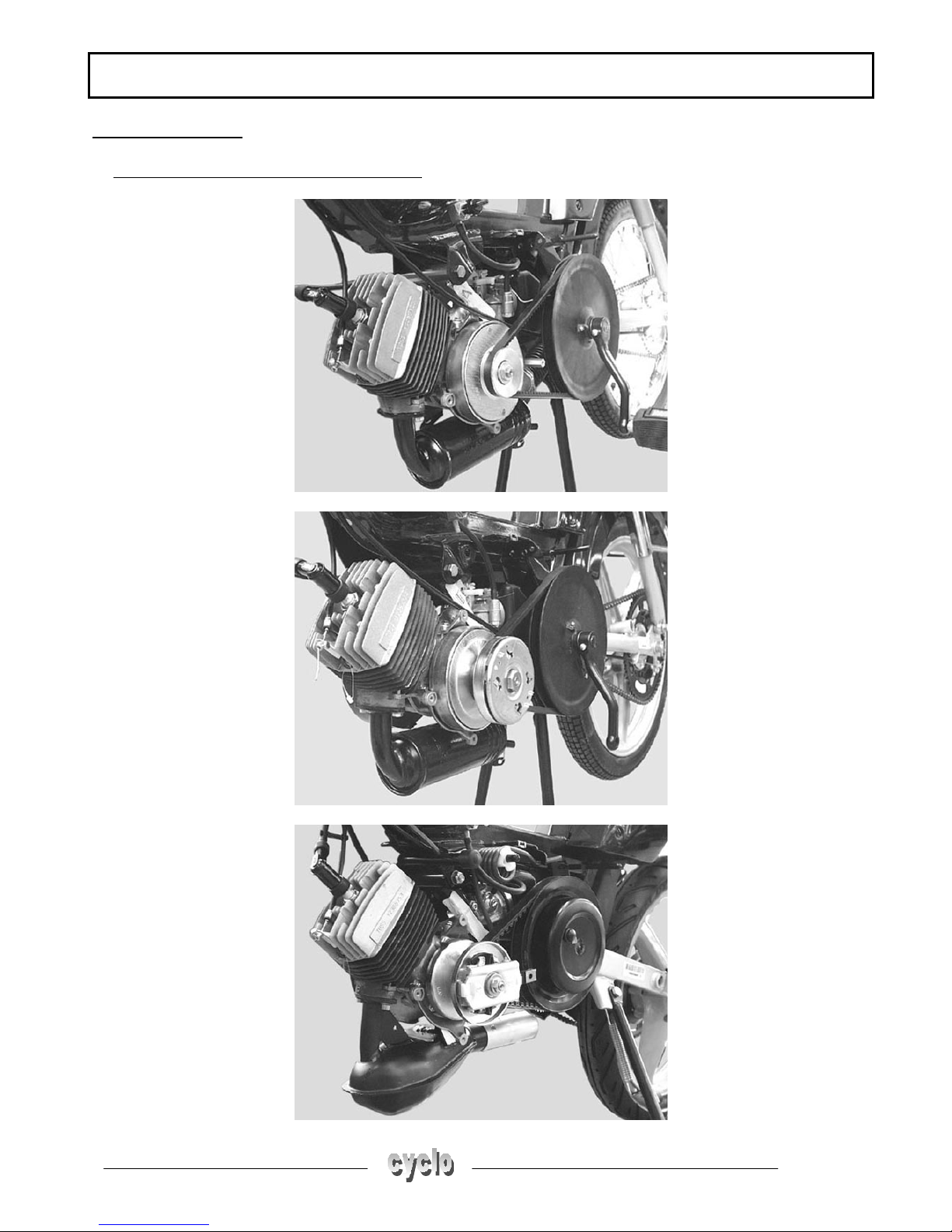
Differences between the 3 types of assembly
- Type 1 without governor and kickstart
- Type 2 with governor and without kickstart
- Type 3 with governor and with kickstart
DISASSEMBLY
Page: 8
Reproduction or translation, even partial, forbidden without the written consent of Peugeot Motocycles
DISASSEMBLY
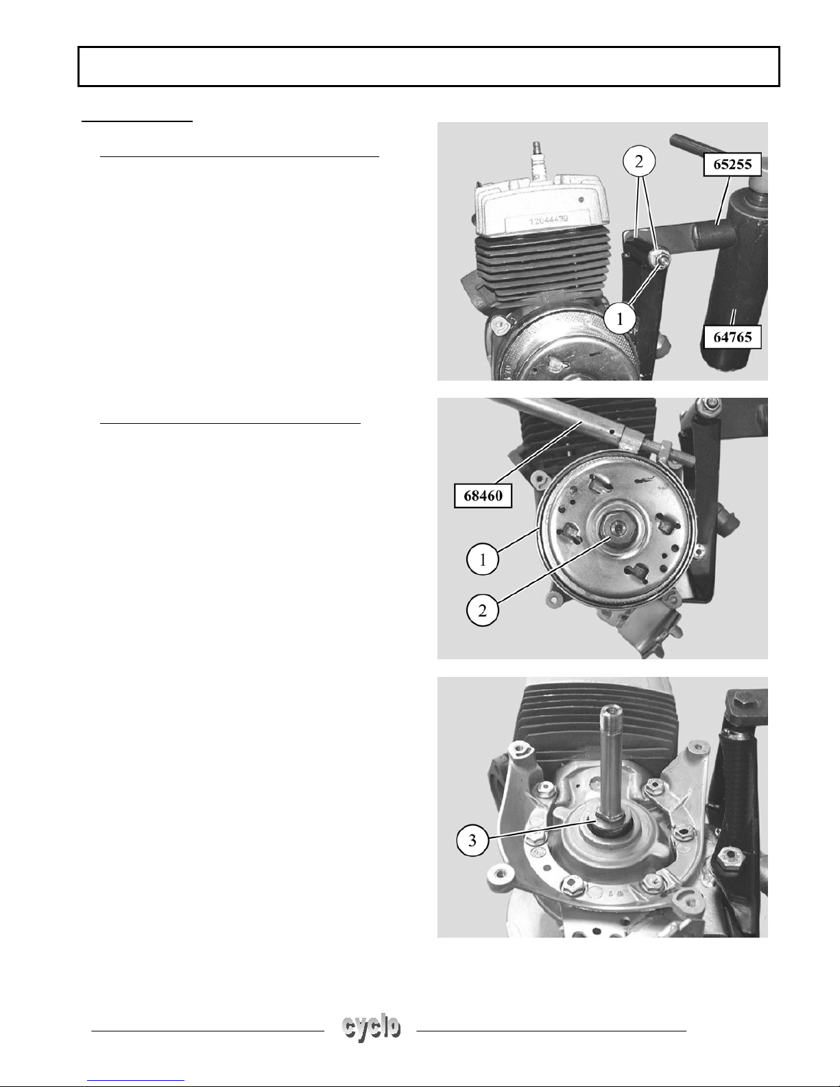
Fitting the engine to the support and adapter
- Fit the engine to adapter P/N 65255 using a nut and
bolt (1) diameter 8 x 110 mm
- Protect both ends of the engine mount with 2
washers (2)
- Fit the engine with its adapter to the stand P/N
64765, with the stand held in a vice
To remove the drive pulley - types 1 and 2
- Lock the clutch drum (1) with the strap 68460
- Remove the nut (2) from the end of the crank
assembly
- Remove the drive pulley not forgetting the washer
(3) under the drum
DISASSEMBLY
Page: 9
Reproduction or translation, even partial, forbidden without the written consent of Peugeot Motocycles
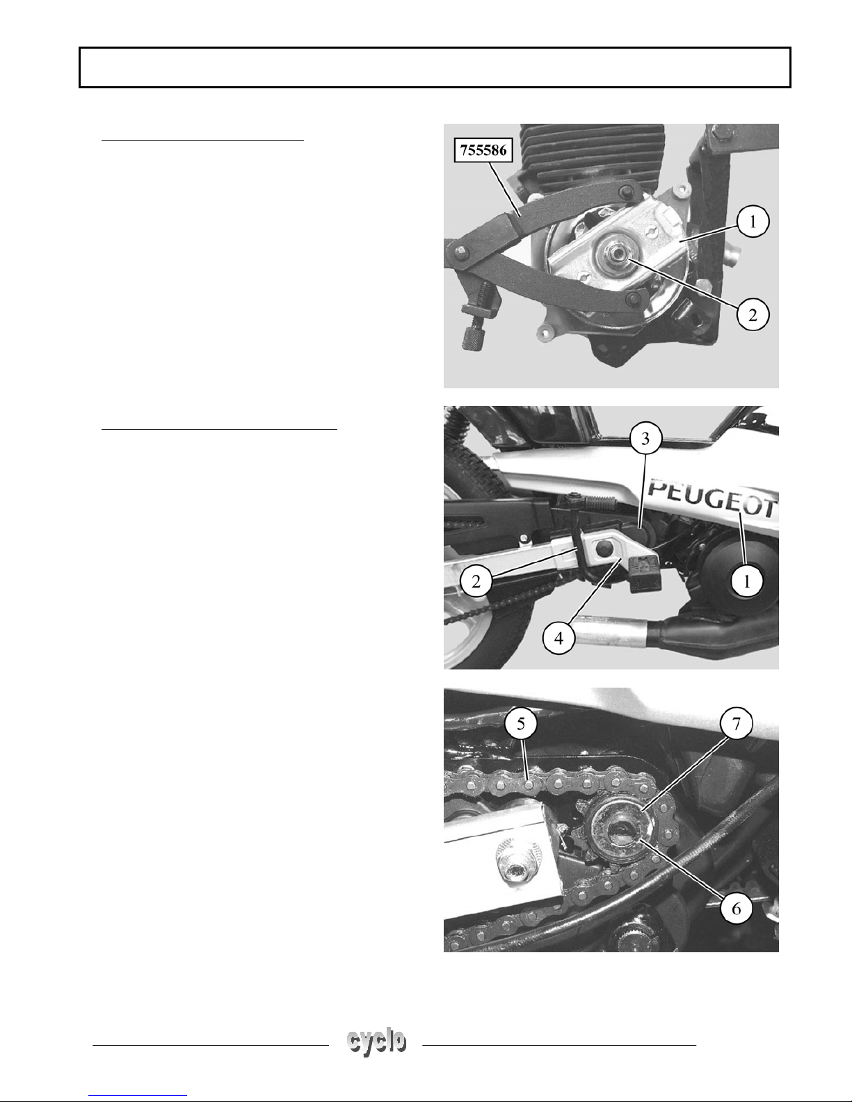
To remove the governor - type 3
Lock the bobweight plate (1) with the adjustable pin
wrench P/N 755586
- Remove the nut (2) from the end of the crank
assembly
- Remove the governor assembly (1)
To remove the clutch pulley assembly
- Remove the panels (1)
- Remove the kickstart lever (2)
- Remove the chain guard (3) and the RH footrest (4)
- Remove the quick-link and the chain (5)
- Remove the circlip (6), the sprocket (7) and its
plastic washer
DISASSEMBLY
Page: 10
Reproduction or translation, even partial, forbidden without the written consent of Peugeot Motocycles
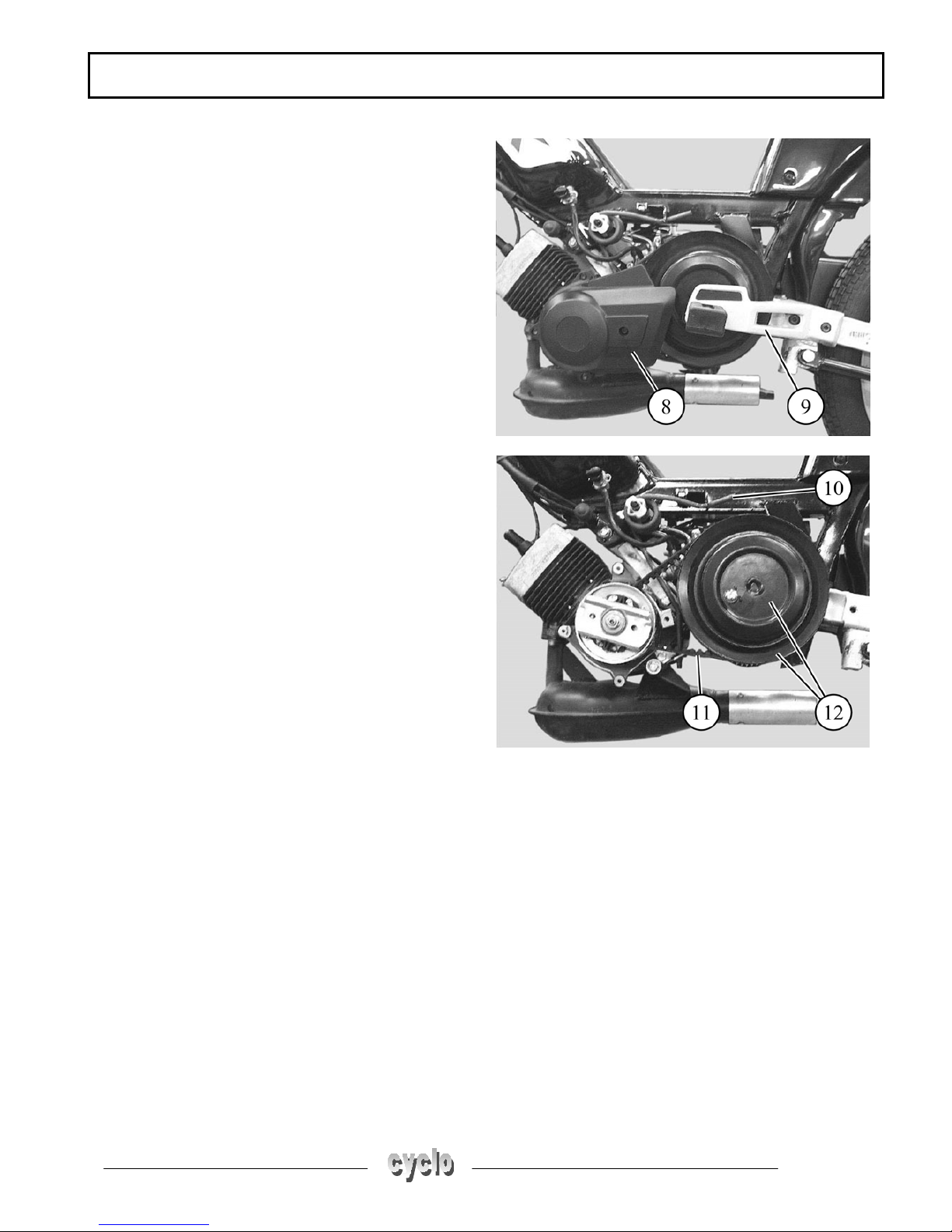
- Remove the governor cover (8)
- Remove the LH footrest (9)
- Slacken the engine tension spring (1)
- Remove the belt (11)
- Remove the clutch/transmission shaft assembly (12)
DISASSEMBLY
Page: 11
Reproduction or translation, even partial, forbidden without the written consent of Peugeot Motocycles
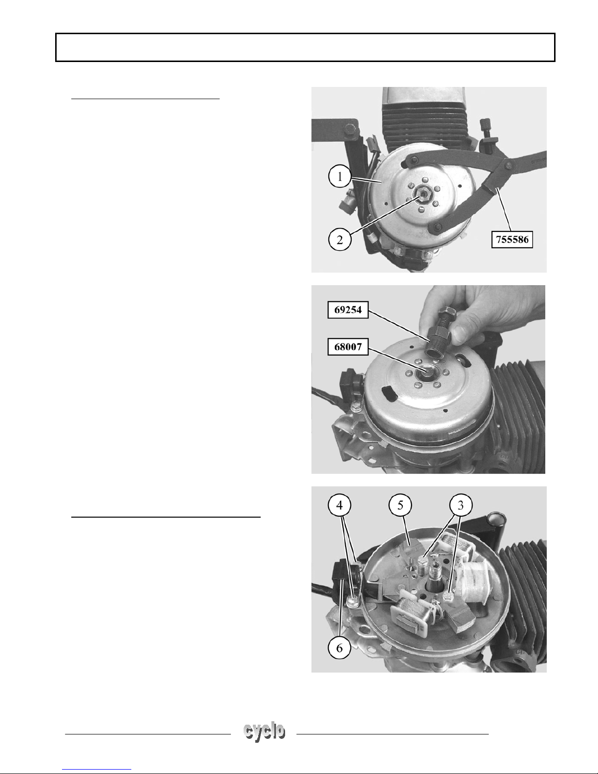
To remove the magneto flywheel
- Remove the flywheel cover
- Lock the rotor (1) with tool P/N 755586
- Remove the nut (2) from the end of the crank
assembly
- Fit protective tool P/N 68007 to the crank assembly
- Fully tighten the flywheel extractor tool P/N 69254
on the rotor
- Lock the rotor with the adjustable pin wrench
P/N 755586
- Tighten the flywheel extractor thrust bolt until the
rotor is freed
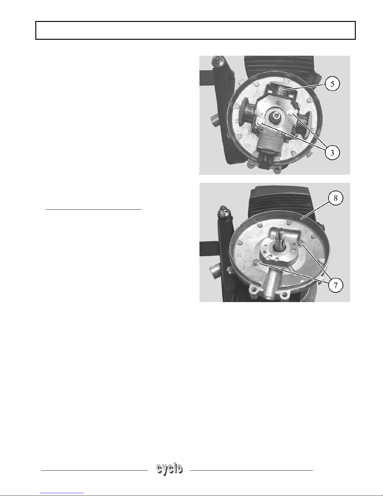
To remove the coil assembly and the stator
Type 1: 6-pole assembly
- Remove the 2 bolts (3) from the coil assembly (5)
and the 2 bolts (4) from the sensor (6)
- Remove the coil assembly
DISASSEMBLY
Page: 12
Reproduction or translation, even partial, forbidden without the written consent of Peugeot Motocycles
Type 2: 4-pole assembly
- Remove the 2 bolts (3) from the coil assembly
- Remove the coil assembly (5)
To remove the coil assembly plate
- Remove the 2 bolts (7) from the stator plate
- Remove the stator plate (8)
DISASSEMBLY
Page: 13
Reproduction or translation, even partial, forbidden without the written consent of Peugeot Motocycles
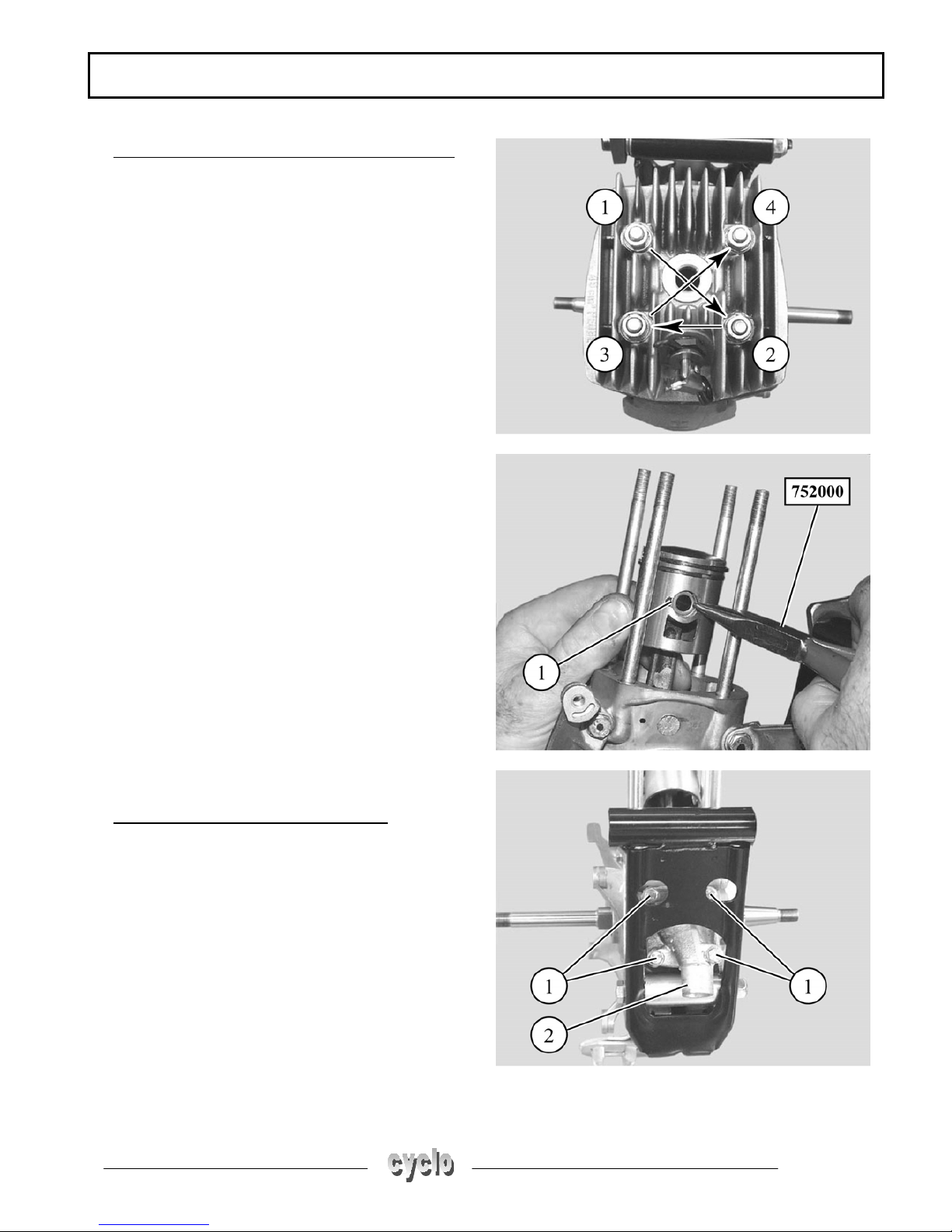
To remove the cylinder head and cylinder/piston
- Remove the 4 cylinder head bolts and lockwashers
in the order shown
- Remove the cylinder head and its gasket
- Remove the cylinder and its gasket
- Remove one of the clips (1) with pliers P/N 752000
- Remove the gudgeon pin and the piston
- Remove the needle bearing cage
To remove the inlet manifold and valve
- Remove the inlet manifold (2) 4 bolts (1)
Remove:
- the inlet manifold
- the inlet valve and its seals
DISASSEMBLY
Page: 14
Reproduction or translation, even partial, forbidden without the written consent of Peugeot Motocycles
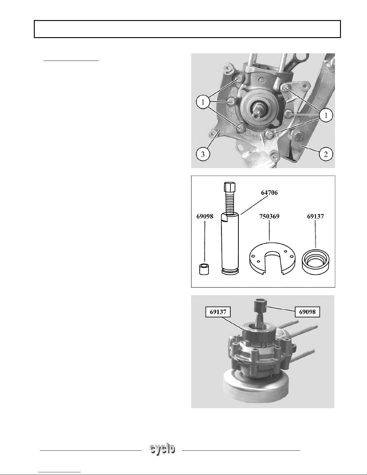
Opening the casings
- Remove the casing 6 assembly nuts and bolts (1)
- Remove the engine mount (2) and the belt guard
bracket (3)
Special tooling required
- Protective cap P/N 69098
- Casing extraction and opening tool P/N 64706
- Casing opening/closing plate P/N 750369
- Casing opening/closing bush P/N 69137
+ Have handy 2 bolts Ø 5 x 40 mm
- On the RH casing, on the magneto flywheel side, fit:
- bush P/N 69137 (large diameter side)
- protector P/N 69098 on the end of the crank
assembly
 Loading...