

Page 1
N
SALES DIVISION
ETWORK TECHNICAL INFORMATION
WORKSHOP MANUAL
Page 2
CONTENTS
CONTENTS
CONTENTS ..................................................................................................................................................... 2
CHARACTERISTICS .................................................................................................................................... 4
Engine characteristics.................................................................................................................................... 4
Engine markings............................................................................................................................................ 4
Frame characteristics..................................................................................................................................... 5
Capacities....................................................................................................................................................... 5
Machine markings ......................................................................................................................................... 5
SERVICE SCHEDULE AND COMMISSIONING..................................................................................... 6
Check:............................................................................................................................................................6
Change:..........................................................................................................................................................6
Check and remove carbon: ............................................................................................................................ 6
Check and lubricate:...................................................................................................................................... 6
Clean and adjust:............................................................................................................................................ 6
Test machine:................................................................................................................................................. 6
Battery preparation (except for maintenance-free battery)*.......................................................................... 7
Checks before handing over to the customer................................................................................................. 7
SPECIAL IMPORTANT POINTS................................................................................................................ 8
Oil and fuel.................................................................................................................................................... 8
TIGHTENING TORQUES AND SPECIAL TOOLS.................................................................................. 9
Tightening torques.........................................................................................................................................9
Body panels: .............................................................................................................................................. 9
Frame:........................................................................................................................................................9
Standard:....................................................................................................................................................9
Special tools:.................................................................................................................................................. 9
CONTROL CABLE AND HARNESS ROUTINGS .................................................................................. 10
Ludix basic version...................................................................................................................................... 10
Ludix luxury version.................................................................................................................................... 12
Caption for Ludix basic and luxury versions............................................................................................... 14
BODY PANELS............................................................................................................................................. 15
Removal of the front leg shield Procedure 1.............................................................................................. 15
Removal of the rear leg shield Procedure 2............................................................................................... 15
Removal of the floor assembly Procedure 3.............................................................................................. 16
Removal of the lower panel......................................................................................................................... 17
FRAME........................................................................................................................................................... 18
Removal of the handlebar Procedure 4...................................................................................................... 18
Removal of the fork or cone, cups, lower ball cage .................................................................................... 19
Steering composition................................................................................................................................... 19
MISCELLANEOUS OPERATIONS........................................................................................................... 20
Removal of the front brake hydraulic hose.................................................................................................. 20
Removal of the rear brake cable.................................................................................................................. 20
Removal of the oil and fuel tank assembly or the tap.................................................................................. 21
Removal of the headlight bulb, instrument panel, speedometer cable........................................................ 22
Removal of the ignition switch.................................................................................................................... 22
Removal of the voltage regulator or high-tension coil................................................................................ 22
Removal of the starter motor relay or CDI module, fuse, oil pump control unit ........................................ 23
Removal of the throttle cable....................................................................................................................... 23
Removal of the horn .................................................................................................................................... 23
Removal of the exhaust Procedure 5.......................................................................................................... 24
Removal of the oil pump ............................................................................................................................. 24
Oil pump bleeding procedure on LUDIX with battery................................................................................ 25
Page: 2
Reproduction or translation, even partial, are forbidden without the written consent of Peugeot Motocycles
Page 3
CONTENTS
Oil pump bleeding procedure on LUDIX without battery........................................................................... 26
WORK ON THE ENGINE WITHOUT REMOVING THE ENGINE.................................................... 27
Removal of the magneto flywheel armature................................................................................................ 27
Removal of the starter motor....................................................................................................................... 27
Removal of the carburettor Procedure 6 .................................................................................................... 27
Removal of the inlet coupling and valves.................................................................................................... 28
Removal of the cylinder and piston............................................................................................................. 28
Removal of the engine mounting linkrod.................................................................................................... 29
ELECTRICITY ............................................................................................................................................. 30
Removal of the main harness....................................................................................................................... 30
ENGINE REMOVAL.................................................................................................................................... 31
Removal of the power unit .......................................................................................................................... 31
Removal of the engine.................................................................................................................................31
FRAME........................................................................................................................................................... 32
Removal of the frame .................................................................................................................................. 32
Frame fitting ................................................................................................................................................ 33
Page : 3
Reproduction or translation, even partial, are forbidden without the written consent of Peugeot Motocycles
Page 4
CHARACTERISTICS
CHARACTERISTICS
Engine characteristics
Engine
2-stroke, exhaust air injection (I.A.E.)
Air cooling
Bore x stroke 39.9 X 39.8
Cubic capacity 49.9 cc
Max. power output 3.2 kW
Max. torque engine
speed
Maximum power
output engine speed
6800 rpm
7100 rpm
Ignition CDI
Spark plug
NGK BR7HS
Eyquem R850
Carburettor Gurtner PY 12
Oil pump control
unit
Dell'Orto
Air pump Dell'Orto
Oil pump Dell'Orto
Magneto Kokusan 89 W
Starter motor Mitsuba 150 W ou Moric 160 W
Exhaust Catalytic
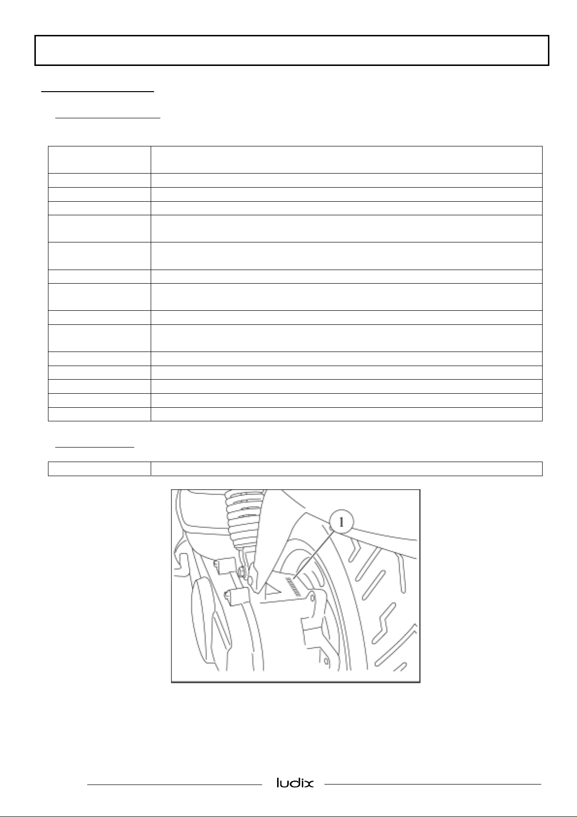
Engine markings
Engine type HA1
1. Engine number
Page: 4
Reproduction or translation, even partial, are forbidden without the written consent of Peugeot Motocycles
Page 5
CARACTERISTICS
Frame characteristics
Capacities
Fuel tank
Oil tank
5.5 litres
Lead-free 95 or 98
1.2 litre
Semi-synthetic oil
0.12 litre
Transfer box
Oil SAE 80W90
Life lubricated
Fork Mechanical
Machine markings
1. Manufacturer’s plate
2. VIN number
Page : 5
Reproduction or translation, even partial, are forbidden without the written consent of Peugeot Motocycles
Page 6
SERVICE SCHEDULE AND COMMISSIONING
SERVICE SCHEDULE AND COMMISSIONING
Heavy duty servicing is for machines used under “harsh” conditions: door-to-door deliveries, intensive urban
use (courier), short journeys with engine cold, dusty areas, ambient temperature over 30°C.
Service operations 500 kms
or 1 months
Every 5000 kms
or 12 months
Every 10000 kms
Heavy duty servicing 500 kms Every 2500 kms Every 5000 kms
Check:
Idle setting X X X
Throttle cable play X X X
Steering column play X X X
Functioning of electrical devices X X X
Condition and adjustment of front and rear
X X X
brake cables *
Condition of fuel pipes X X X
Condition of oil pipes X X X
Condition of front brake fluid pipe X X X
Tyre pressures X
Tyre condition, pressure and wear X X
Brake fluid level X X X
Battery electrolyte level * X X X
Tightness of nuts and bolts X X X
Change:
Spark plug X X
Inlet silencer X
Front brake pads or linings # X X
Rear brake linings * # X
Drive pulley rollers # X X
Transmission belt X
Check and remove carbon:
Piston X
Cylinder head X
Exhaust port X
Check and lubricate:
Expanding flange driven pulley and needle
X
cages
Drive pulley / expanding flange X X
Kickstart drive gear and kickstart shaft X X
Front and rear brake cam X X
Clean and adjust:
Carburettor X
Test machine:
On road X X X
* Depending on equipment
# If necessary
Page: 6
Reproduction or translation, even partial, are forbidden without the written consent of Peugeot Motocycles
Page 7
SERVICE SCHEDULE AND COMMISSIONING
Battery preparation (except for maintenance-free battery)*
- Remove the battery
- Remove the 6 filler caps and the vent plug
- Fill the battery with electrolyte to the level marked UPPER LEVEL
- Electrolyte: (35% sulphuric acid = 1.28g/cm3) 1 litre can ref: 752740, 5 litre can ref: 752741.
- Leave the battery to stand for around half an hour
- Top up if necessary
- Charge the battery for at least 2 hours with a current of 400 mA (0.4A)
- Refit the battery and connect the vapour vent pipe
- Connect the red wires to the + terminal and the green wire to the - terminal
- Then, the battery level should be topped up if necessary, after fully charging, using distilled water only.
Checks before handing over to the customer
- Check the wheel nuts are tight
- Check nuts and bolts are tight
- Check brake adjustment and efficiency
- Check the tyre pressures cold
- Check operation of the lights, flashers *, horn, and brake light
- Check the different warning lights work
- Carry out a road test
* Depending on equipment
Page : 7
Reproduction or translation, even partial, are forbidden without the written consent of Peugeot Motocycles
Page 8
SPECIAL IMPORTANT POINTS
SPECIAL IMPORTANT POINTS
Oil and fuel
This machine is designed to run on super 95 or 98 unleaded fuel
The oil to use for the separate lubrication system is semi-synthetic oil
The oil pump must be bled according to the methods specified depending on the models.
The air pipe between the air pump and the exhaust has specific heat resistance properties.
In case of replacement, an original pipe must be fitted.
For machines equipped with a battery, the instrument panel oil warning light comes on when the ignition is
turned on and then goes off when the engine starts ; this means that the lubrication system warning light and
electrical circuit are operational
Page: 8
Reproduction or translation, even partial, are forbidden without the written consent of Peugeot Motocycles
Page 9
TIGHTENING TORQUES AND SPECIAL TOOLS
TIGHTENING TORQUES AND SPECIAL TOOLS
Tightening torques
Body panels:
Bottom panel 0.4 m.daN
Floor 0.4 m.daN
Handlebar cover 0.1 m.daN
Front panel 0.1 m.daN
Rear shield 0.1 m.daN
Side fairings 0.1 m.daN
Front mudguard 0.8 m.daN
Grab handle 1.2 m.daN
Frame:
Front wheel spindle nut 6 m.daN
Rear wheel spindle nut 10 m.daN
Engine to rod pivot 5.2 m.daN
Frame to rod pivot 5.2 m.daN
Shock absorber top mount 4.3 m.daN
Shock absorber bottom mount 2 m.daN
Exhaust to cylinder mounting nut 1.5 m.daN
Exhaust fixing bolt on engine casing 2 m.daN
Upper cone (in 2 operations) 4 and 2.3 m.daN
Steering locknut 7 m.daN
Front brake caliper 2.5 m.daN
Front brake disc 1 m.daN
Standard:
Nut and bolt 5 mm diameter 0.5 m.daN
Nut and bolt 6mm diameter 1 m.daN
Nut and bolt 8mm diameter 2.2 m.daN
Nut and bolt 10mm diameter 3.5 m.daN
Nut and bolt 12mm diameter 5.5 m.daN
Special tools:
Designation Reference
Hose clamp 755996
Steering column wrench 757860
Oil circuit bleeding harness 757854
Page : 9
Reproduction or translation, even partial, are forbidden without the written consent of Peugeot Motocycles
Page 10
CONTROL CABLE AND HARNESS ROUTINGS
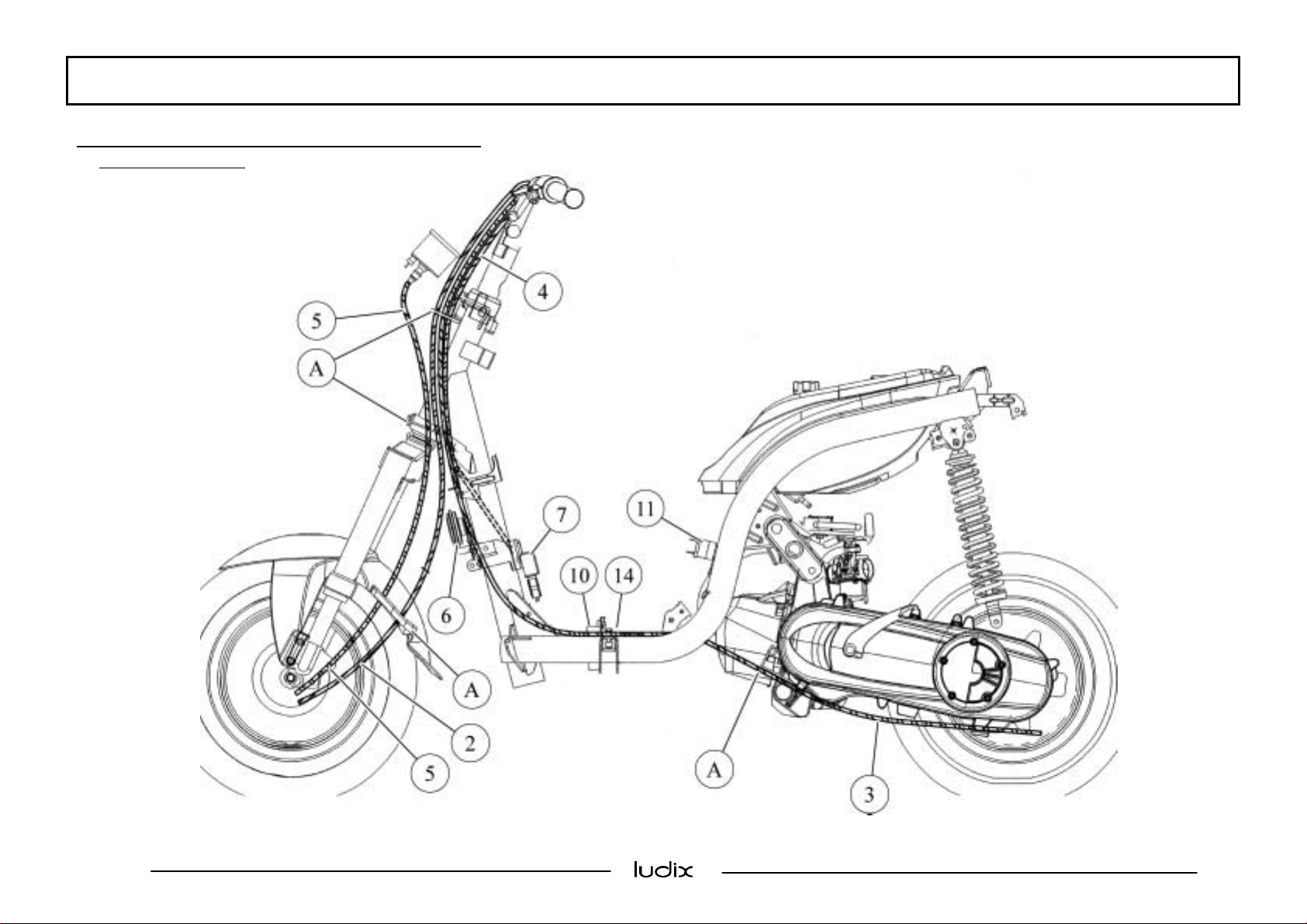
CONTROL CABLE AND HARNESS ROUTINGS
Ludix basic version
Page: 10
Reproduction or translation, even partial, are forbidden without the written consent of Peugeot Motocycles
Page 11
CONTROL CABLE AND HARNESS ROUTINGS
Page : 11
Reproduction or translation, even partial, are forbidden without the written consent of Peugeot Motocycles
Page 12

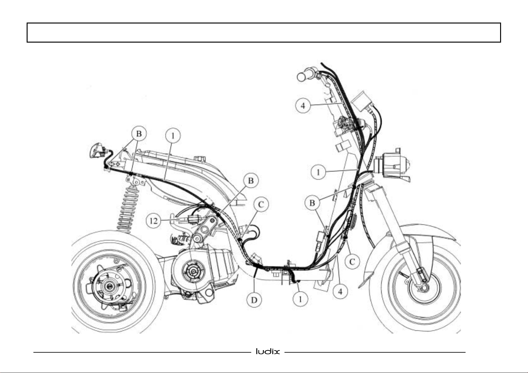
Ludix luxury version
CONTROL CABLE AND HARNESS ROUTINGS
Page: 12
Reproduction or translation, even partial, are forbidden without the written consent of Peugeot Motocycles
Page 13

CONTROL CABLE AND HARNESS ROUTINGS
Page : 13
Reproduction or translation, even partial, are forbidden without the written consent of Peugeot Motocycles
Page 14

Caption for Ludix basic and luxury versions
1. Main harness
2. Front brake cable
3. Rear brake cable
4. Throttle cable
5. Speedometer cable
6. Horn
7. Regulator
8. Fuse
9. Battery
10.Oil pump control unit
11. HT coil
12. Oil pump
13.Starter motor relay
14.CDI ignition unit
A. Cable sheath guide
B. Clip for positioning the harness on the frame
C. Clip
D. Plastic tie
CONTROL CABLE AND HARNESS ROUTINGS
Page: 14
Reproduction or translation, even partial, are forbidden without the written consent of Peugeot Motocycles
Page 15

BODY PANELS
BODY PANELS
Removal of the front leg shield Procedure 1
- Disconnect the speedometer cable from the drive
system
- Unclip the front mudguard cable clip
- Remove the leg shield 4 fixing bolts (1)
- Unclip the rubber protector (2)
- Disconnect the headlight
- Disconnect the instrument cluster (3)
- Remove the front leg shield
Removal of the rear leg shield Procedure 2
- Remove the front leg shield (see procedure 1)
- Remove the rear leg shield 4 fixing bolts (1)
Page : 15
Reproduction or translation, even partial, are forbidden without the written consent of Peugeot Motocycles
Page 16

BODY PANELS
Remove the ignition switch key
- Unclip the rear leg shield from the footboard
assembly (A)
- Remove the rear leg shield
Removal of the floor assembly Procedure 3
- Remove the rear shield panel (see procedure 2)
- Remove the shock absorber trim (1) (1 screw)
- Remove the rear side fairings (2) (2 screws each)
- Remove the 2 clips (2) to avoid scratches on the
frame
- Remove the cap / footrest assembly (4) (1 screw
each)
- Remove the floor 2 fixing bolts (5)
- Remove the floor assembly
Page: 16
Reproduction or translation, even partial, are forbidden without the written consent of Peugeot Motocycles
Page 17

BODY PANELS
Removal of the lower panel
- Remove the floor assembly (see procedure 3)
- Unhook the lower panel (1) from the frame
- - Pivot the lower panel to the right in order to
release the frame front clip
Page : 17
Reproduction or translation, even partial, are forbidden without the written consent of Peugeot Motocycles
Page 18

BODY PANELS
FRAME
Removal of the handlebar Procedure 4
- Remove the rear shield panel (see procedure 2)
- Disconnect the RH and LH flashers from the main
harness
- Remove the handlebar front cover 4 fixing bolts (1)
- - Remove the handlebar rear cover 3 fixing bolts (2)
- - Remove the RH and LH grips (3)
- Remove the handlebar central fixing bolt (4)
- Remove the handlebar
Page: 18
Reproduction or translation, even partial, are forbidden without the written consent of Peugeot Motocycles
Page 19

FRAME
Removal of the fork or cone, cups, lower ball cage
- Remove the rear shield panel (see procedure 2)
- Remove the front mudguard (1)
- Slacken the front wheel spindle nut (2)
- Remove the 2 front brake caliper bolts (3)
- Suspend the front caliper without disconnecting it
- Remove the front wheel
- - Remove the handlebar central fixing screw and bolt
(4)
- Suspend the handlebar
- Remove the steering nut and its stack using tool par
number: 757860
- Remove the fork
Note
: it is recommended to check that the ball cages,
raceway and steering cone are in good condition and to
replace them if necessary
Steering composition
1. Self-lubricating lower ball cage
2. Upper ball cage
3. Adjustable cone
4. Rubber washer
5. Locknut
6. Lockwasher
Page : 19
Reproduction or translation, even partial, are forbidden without the written consent of Peugeot Motocycles
Page 20

MISCELLANEOUS OPERATIONS
MISCELLANEOUS OPERATIONS
Removal of the front brake hydraulic hose
- Remove the rear shield panel (see procedure 2)
- Remove the handlebar front cover 4 fixing bolts
- Remove the handlebar front cover
- Protect any plastics which may be exposed to brake
fluid splashes
- Remove the screws (1) from the hydraulic hose to
the master cylinder and to the brake caliper
- Remove the brake hydraulic hose
When refitting, bleed the brake circuit
Removal of the rear brake cable
- Remove the rear shield panel (see procedure 2)
- Remove the handlebar front cover
- Remove the brake cable (1)
Note:
- When refitting, first insert the cable into the guide
(2) and take it out through the battery cover at (A)
- - Then, insert the cable in the battery cover again
and take it out at the rear side of the floor (B)
- Make sure the cable passes through its different
guides
Page: 20
Reproduction or translation, even partial, are forbidden without the written consent of Peugeot Motocycles
Page 21

MISCELLANEOUS OPERATIONS
Removal of the oil and fuel tank assembly or the tap
- Remove the fixing bolt (1) from the saddle and the
tank
- Remove the saddle
- Remove the tank assembly rear fixing nut (2)
- - Disconnect the oil level low switch from the
harness (3) under the tank
- Close the fuel tap
- Disconnect the fuel pipe (4) from the tap
- Place a hose clamp P/N 755996 on the oil feed pipe
to the oil pump (5)
- Disconnect the oil pump inlet pipe
- Remove the oil and fuel tank assembly
Note
: Using a clean cloth, protect the pump against
dirt splashes
When refitting, bleed the oil pump according to the
recommended method
Page : 21
Reproduction or translation, even partial, are forbidden without the written consent of Peugeot Motocycles
Page 22

MISCELLANEOUS OPERATIONS
Removal of the headlight bulb, instrument panel, speedometer cable
- Remove the front leg shield (see procedure 1)
- Unclip the rubber protector (1)
- Remove the headlight bulb
- Remove the 3 headlight fixing bolts (2)
- Remove the headlight
- Remove the 3 instrument panel fixing bolts (3)
- Remove the instrument panel and/or with the
speedometer cable
Note
: When removing the speedometer cable, the
headlight must be removed
Removal of the ignition switch
- Remove the rear shield panel (see procedure 2)
- Disconnect the ignition switch
- Remove the tamperproof bolt (1) using an adapted
tool
- Remove the ignition switch
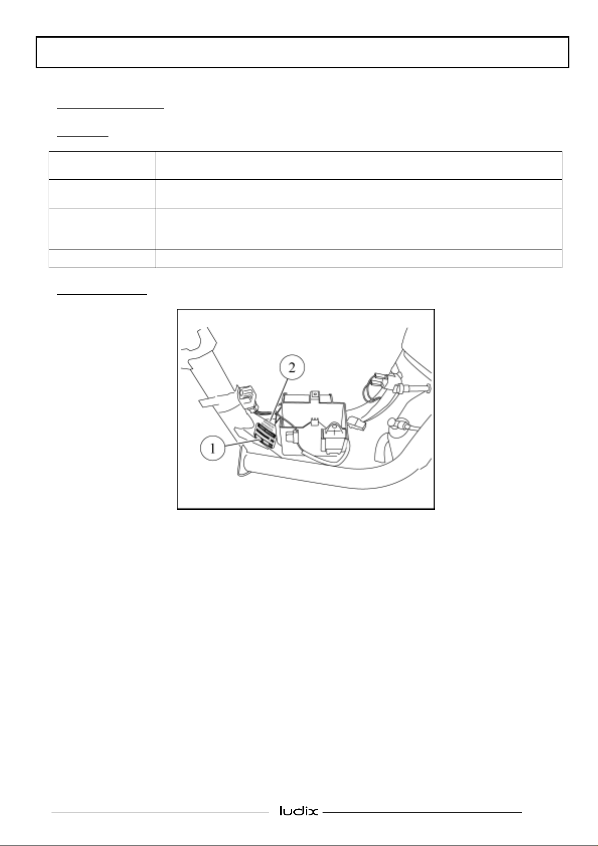
Removal of the voltage regulator or high-tension coil
- Remove the battery cover (1 screw)
- Disconnect and remove the battery (1 screw)
- Disconnect and remove the voltage regulator (1) or
the high-tension coil (2) (1 screw each) from the
battery cover
Page: 22
Reproduction or translation, even partial, are forbidden without the written consent of Peugeot Motocycles
Page 23

MISCELLANEOUS OPERATIONS
Removal of the starter motor relay or CDI module, fuse, oil pump control unit
- Remove the battery cover (1 screw)
- Disconnect the battery
- Disconnect and remove the element concerned (1)
from the battery cover
Note:
All these elements are placed in supports which
are integrated in the battery compartment
Removal of the throttle cable
- Remove the floor assembly (see procedure 3)
- Remove the RH grip (2 screws)
- Release the accelerator cable by turning it 1/4 of a
turn
- Remove the carburettor chamber cover
- Remove the valve
- Unclip the cable from the cable clips and plastic tie
(1) on the frame
- Remove the throttle cable (2)
Note:
On Ludix basic version, the throttle cable is a
cable adjusted and cut according to the customer's
requirements, connected to the turning handle
The cable must be changed each time it is removed
Removal of the horn
- Remove the floor assembly (see procedure 3)
- Disconnect the horn (1)
- Remove the horn
Page : 23
Reproduction or translation, even partial, are forbidden without the written consent of Peugeot Motocycles
Page 24

MISCELLANEOUS OPERATIONS
Removal of the exhaust Procedure 5
- Disconnect the air pipe (1) from the exhaust
- Remove the 2 exhaust nuts on the cylinder nose
- Remove the 2 fixing bolts (2) from the exhaust and
the stiffener plate (3) on the engine casing
- Remove the exhaust
Note:
The 2 exhaust fixing bolts on the engine casing
are pre-coated with locking compound and must be
changed when they are removed, including the
exhaust seal at cylinder end
Removal of the oil pump
- Remove the oil pump (1) fixing bolt
- Disconnect the oil pump connecting pipes
- Disconnect the oil pump
- Remove the oil pump
Note
: The oil pump circuit must be bled according to
the specified procedure each time a work is carried
out on the lubrication system
Page: 24
Reproduction or translation, even partial, are forbidden without the written consent of Peugeot Motocycles
Page 25

MISCELLANEOUS OPERATIONS
Oil pump bleeding procedure on LUDIX with battery
- Check the level in the oil tank
- Check the ignition is off.
- Disconnect the oil pump
- Disconnect the oil inlet pipe from the carburettor
- Use a recipient to recover the oil when bleeding
- Turn on the ignition
- Connect the oil pump
Note:
The procedure starts with a slow pumping during 4-5
minutes, followed by a faster pumping during 30
seconds.
During the bleeding procedure, the instrument panel
oil warning light flashes as the pump is activated and
stays on at the end of the bleeding.
During bleeding, ensure the oil flows regularly and
there are no air bubbles in the pipe
Otherwise, repeat the operation
- Turn off the ignition
- Connect the oil inlet pipe to the carburettor
Page : 25
Reproduction or translation, even partial, are forbidden without the written consent of Peugeot Motocycles
Page 26

MISCELLANEOUS OPERATIONS
Oil pump bleeding procedure on LUDIX without battery
- Prepare a battery correctly loaded
- Check the level in the oil tank
- Disconnect the oil pump
- Remove the battery cover
- Disconnect the voltage regulator
- Connect the red wire on the supply harness P/N
757854 to the red wire on the regulator connector
(A)
- Connect the green wire on the supply harness to the
ground screw on the casing cover (B)
- Connect the 2 supply harness wires to the battery
(red to + and green to -)
- Disconnect the oil inlet pipe from the carburettor
- Use a recipient to recover the oil when bleeding
- Connect the oil pump to begin the procedure
Note
: The procedure starts with a slow pumping
during 4-5 minutes, followed by a faster pumping
during 30 seconds.
During the bleeding procedure, the instrument panel
oil warning light flashes as the pump is activated and
stays on at the end of the bleeding.
During bleeding, ensure the oil flows regularly and
there are no bubbles in the pipe
Otherwise, repeat the operation
- Disconnect the battery and the supply harness
- Connect the voltage regulator
- Connect the oil inlet pipe to the carburettor
Page: 26
Reproduction or translation, even partial, are forbidden without the written consent of Peugeot Motocycles
Page 27

WORK ON THE ENGINE WITHOUT REMOVING THE ENGINE
WORK ON THE ENGINE WITHOUT
REMOVING THE ENGINE
Removal of the magneto flywheel armature
- Remove the exhaust (see procedure 5)
- Remove the battery cover (1 screw)
- Disconnect and remove the battery (1 screw)
- Disconnect the armature from the main harness (in
the lower panel)
Note
: See the 50cc Engine, Horizontal Cylinder, IAE
workshop manual for removal of the cooling volute,
magneto flywheel rotor and armature
Removal of the starter motor
- Remove the battery cover (1 screw)
- Disconnect and remove the battery (1 screw)
- Disconnect the starter motor from the main harness
(in the lower panel, from the battery cover)
- Remove the starter motor (1) 2 bolts
- Remove the starter motor
Removal of the carburettor Procedure 6
- Remove the shock absorber trim
- Remove the LH side fairing
- Close the fuel tap
- Disconnect the air pipe (1) from the air filter
housing (2)
- Remove the air filter housing (1 screw and 1 clip)
Page : 27
Reproduction or translation, even partial, are forbidden without the written consent of Peugeot Motocycles
Page 28

WORK ON THE ENGINE WITHOUT REMOVING THE ENGINE
- Disconnect the choke (3) from the main harness
- Disconnect the fuel (4) and separate lubrication (5)
pipes
- Remove the chamber cover (6) (1 bolt)
- Disconnect the throttle cable
- Remove the carburettor (1 clip)
Removal of the inlet coupling and valves
- Remove the carburettor (see procedure 6)
Note:
See the 50cc Engine, Horizontal Cylinder, IAE
workshop manual for removal of the inlet coupling
and valves
Removal of the cylinder and piston
- Remove the floor assembly (see procedure 3)
- Remove the exhaust (see operation 5)
Note
: See the 50 cc Engine, Horizontal Cylinder, IAE
workshop manual for removal of the cylinder cover,
cylinder head, cylinder and piston.
Page: 28
Reproduction or translation, even partial, are forbidden without the written consent of Peugeot Motocycles
Page 29

WORK ON THE ENGINE WITHOUT REMOVING THE ENGINE
Removal of the engine mounting linkrod
- Remove the shock absorber trim (1 screw)
- Remove the side fairings (2 screws each)
- Remove the shock absorber lower mount (1)
- Suspend the rear of the machine
- Remove the 2 linkrod fixing pins (2)
- Remove the engine mounting linkrod
Note
: When refitting, ensure correct positioning of
the rubber bump stop of the engine mounting linkrod
Page : 29
Reproduction or translation, even partial, are forbidden without the written consent of Peugeot Motocycles
Page 30

ELECTRICITY
ELECTRICITY
Removal of the main harness
- Remove the floor assembly (see procedure 3)
- Remove the handlebar front cover
- Depending on the model, disconnect:
the battery
the brake light switches
the steering lock
the RH and LH switches
the front direction indicators
the horn
the voltage regulator
the CDI unit
the starter motor relay
the oil pump control unit
the high tension coil
the magneto flywheel armature
the starter motor
the choke
the oil level low switch
the oil pump
the rear light
the rear direction indicators
- Unclip the harness from its supports on the frame and cut the plastic ties
- Remove the main harness
Page: 30
Reproduction or translation, even partial, are forbidden without the written consent of Peugeot Motocycles
Page 31

ENGINE REMOVAL
ENGINE REMOVAL
Removal of the power unit
- Remove the battery cover
- Disconnect and remove the battery
- Disconnect the choke, suppressor, ignition rotor and starter motor (depending on model) from the main
harness
- Close the fuel tap
- Disconnect the oil level low switch from the main harness under the fuel tank
- Disconnect the carburettor throttle cable and the fuel and oil supply pipes
- Disconnect the rear brake cable
- Suspend the rear of the machine
- Remove the engine to rod fixing pin
- Remove the shock absorber lower mount
- Remove the power unit
Removal of the engine
- Remove the rear mudguard
- Remove the exhaust
- Remove the rear wheel
- Remove the stand
- Remove the kickstart pedal
- Remove the air filter housing
- Remove the carburettor
Page : 31
Reproduction or translation, even partial, are forbidden without the written consent of Peugeot Motocycles
Page 32

FRAME
FRAME
Removal of the frame
This method is used only when changing the frame only, with the removal of several assemblies
When changing the frame due to an accident, the method must be completed by the repair or replacement of
damaged items
- Remove the battery cover
- Disconnect and remove the battery (depending on model)
- Remove the floor assembly (see procedure 3)
- Remove the lower panel
- Remove the handlebar front cover
- Remove the throttle cable from the grip
- Remove from the main harness:
the LH or RH control clusters
the front direction indicators
- Remove the metal clamp from the front brake cable
- Disconnect and remove the steering lock
- Remove the tube pivot handlebar shaft
- Tilt the handlebar assembly
- Remove the fork assembly with the wheel
- Remove the horn and the voltage regulator without disconnecting them
- Remove the battery tray with the starter motor relay, oil pump control unit and CDI unit without
disconnecting them
- Disconnect and remove the high tension coil
- Disconnect the starter motor and magneto flywheel harnesses from the main harness
- Close the fuel tap
- Disconnect the oil level low switch
- Remove the saddle, tank assembly and storage compartment
- Remove the oil pump without disconnecting it
- Remove the grab handle
- Remove the rear light and rear direction indicator assembly without disconnecting them
- Remove the shock absorber upper mount
- Remove the engine linkrod to frame shaft
- Unclip the harness from the frame and cut the plastic ties
- Remove the frame
- Remove the manufacturer's plate (A), captive nuts and linkrod rubber bump stop
Page: 32
Reproduction or translation, even partial, are forbidden without the written consent of Peugeot Motocycles
Page 33

FRAME
Frame fitting
- Engrave the VIN number
- Fit the manufacturer’s plate
- Fit the upper and lower steering cups
- Fit the steering lock
Note:
Use a shear bolt when refitting the steering lock
- Fit the frame on the power unit
- Fit the shaft on the engine mounting linkrod
- Fit the shock absorber upper mount
- Grease the upper steering cup
- Position the self-lubricating ball cage in the lower cup
- Fit the fork assembly in the fork tube
- Position the ball cage in the upper cup
- Position the steering nuts and washers
Note:
Once the steering play has been assembled and tightened according to the recommended torques, check
for correct steering functional clearance
- Position the handlebar assembly
- Position and tighten the handlebar fixing bolt and nut
- Fit the main harness, starter motor harness and flywheel output harness (clips and plastic ties) on the frame
RH side once they have been connected
- Position and connect the high tension coil
- Position the battery tray
- Position the voltage regulator, starter motor relay, CDI unit and oil pump control unit in the battery tray
supports
- Position and connect the horn
- Connect the steering lock
- Fit the brake and throttle cables on the frame LH side
- Fit the fuel and oil tank assembly
- Connect the fuel and oil tank supply pipes
- Connect the choke
- Connect the oil level low switch to the main harness under the tank assembly
- Fit the saddle
- Fit the floor assembly (see procedure 3, in reverse order to removal)
- Connect the rear light
- Position and connect the battery
- Fit the battery cover
Note:
Test all electrical functions of the machine
Carry out a road test to check the machine as a whole
Page : 33
Reproduction or translation, even partial, are forbidden without the written consent of Peugeot Motocycles
Page 34

RECOMMENDS
REF: 757812
For reasons of continuous improvement, Peugeot Motocycles reserves the right to modify, delete or add any part number quoted
DC/PS/ATR printed in EU 02/2004 (photos non-contractual)
Reproduction or translation, even partial, are forbidden without the written consent of Peugeot Motocycles
 Loading...