

Page 1

Operation and
Maintenance
Manual
SEBU9073 (en-us)
December 2015
404A-22SG1 Gas Industrial Engine
EX1 1-UP (Engine)
Page 2
Important Safety Information
Most accidents that involve product operation, maintenance and repair are caused by failure to
observe basic safety rules or precautions. An accident can often be avoided by recognizing potentially
hazardous situations before an accident occurs. A person must be alert to potential hazards. This
person should also have the necessary training, skills and tools to perform these functions properly.
Improper operation, lubrication, maintenance or repair of this product can be dangerous and
could result in injury or death.
Do not operate or perform any lubrication, maintenance or repair on this product, until you have
read and understood the operation, lubrication, maintenance and repair information.
Safety precautions and warnings are provided in this manual and on the product. If these hazard
warnings are not heeded, bodily injury or death could occur to you or to other persons.
The hazards are identified by the “Safety Alert Symbol” and followed by a “Signal Word” such as
“DANGER”, “WARNING” or “CAUTION”. The Safety Alert “WARNING” label is shown below.
The meaning of this safety alert symbol is as follows:
Attention! Become Alert! Your Safety is Involved.
The message that appears under the warning explains the hazard and can be either written or
pictorially presented.
Operations that may cause product damage are identified by “NOTICE” labels on the product and in
this publication.
Perkins cannot anticipate every possible circumstance that might involve a potential hazard. The
warnings in this publication and on the product are, therefore, not all inclusive. If a tool, procedure,
work method or operating technique that is not specifically recommended by Perkins is used,
you must satisfy yourself that it is safe for you and for others. You should also ensure that the
product will not be damaged or be made unsafe by the operation, lubrication, maintenance or
repair procedures that you choose.
The information, specifications, and illustrations in this publication are on the basis of information that
was available at the time that the publication was written. The specifications, torques, pressures,
measurements, adjustments, illustrations, and other items can change at any time. These changes can
affect the service that is given to the product. Obtain the complete and most current information before
you start any job. Perkins dealers or Perkins distributors have the most current information available.
When replacement parts are required for this
product Perkins recommends using Perkins
replacement parts.
Failure to heed this warning can lead to premature failures, product damage, personal injury or
death.
Page 3

SEBU9073
3
Table of Contents
Table of Contents
Foreword ........................................................... 4
Safety Section
Safety Messages............................................... 5
General Hazard Information.............................. 5
Burn Prevention................................................. 8
Fire Prevention and Explosion Prevention........ 9
Crushing Prevention and Cutting Prevention...11
Mounting and Dismounting ..............................11
Ignition Systems ...............................................11
Before Starting Engine .....................................11
Engine Starting .................................................11
Maintenance Interval Schedule....................... 34
Reference Information Section
Reference Materials ........................................ 51
Index Section
Index................................................................ 53
Engine Stopping .............................................. 12
Electrical System............................................. 12
Product Information Section
Model Views and Specifications...................... 13
Product Identification Information ................... 16
Operation Section
Lifting and Storage .......................................... 17
Gauges and Indicators .................................... 19
Features and Controls..................................... 20
Engine Starting ................................................ 23
Engine Operation ............................................ 26
Engine Stopping .............................................. 27
Maintenance Section
Refill Capacities............................................... 28
Page 4

4
Foreword
SEBU9073
Foreword
Literature Information
This manual contains safety, operation instructions,
lubrication and maintenance information. This
manual should be stored in or near the engine area in
a literature holder or literature storage area. Read,
study and keep it with the literature and engine
information.
English is the primary language for all Perkins
publications. The English used facilitates translation
and consistency.
Some photographs or illustrations in this manual
show details or attachments that may be different
from your engine. Guards and covers may have been
removed for illustrative purposes. Continuing
improvement and advancement of product design
may have caused changes to your engine which are
not included in this manual. Whenever a question
arises regarding your engine, or this manual, please
consult with your Perkins dealer or your Perkins
distributor for the latest available information.
Safety
This safety section lists basic safety precautions. In
addition, this section identifies hazardous, warning
situations. Read and understand the basic
precautions listed in the safety section before
operating or performing lubrication, maintenance and
repair on this product.
Operation
Operating techniques outlined in this manual are
basic. They assist with developing the skills and
techniques required to operate the engine more
efficiently and economically. Skill and techniques
develop as the operator gains knowledge of the
engine and its capabilities.
The operation section is a reference for operators.
Photographs and illustrations guide the operator
through procedures of inspecting, starting, operating
and stopping the engine. This section also includes a
discussion of electronic diagnostic information.
Maintenance
The maintenance section is a guide to engine care.
The illustrated, step-by-step instructions are grouped
by service hours and/or calendar time maintenance
intervals. Items in the maintenance schedule are
referenced to detailed instructions that follow.
Recommended service should be performed at the
appropriate intervals as indicated in the Maintenance
Interval Schedule. The actual operating environment
of the engine also governs the Maintenance Interval
Schedule. Therefore, under extremely severe, dusty,
wet or freezing cold operating conditions, more
frequent lubrication and maintenance than is
specified in the Maintenance Interval Schedule may
be necessary.
The maintenance schedule items are organized for a
preventive maintenance management program. If the
preventive maintenance program is followed, a
periodic tune-up is not required. The implementation
of a preventive maintenance management program
should minimize operating costs through cost
avoidances resulting from reductions in unscheduled
downtime and failures.
Maintenance Intervals
Perform maintenance on items at multiples of the
original requirement. We recommend that the
maintenance schedules be reproduced and
displayed near the engine as a convenient reminder.
We also recommend that a maintenance record be
maintained as part of the engine's permanent record.
Your authorized Perkins dealer or your Perkins
distributor can assist you in adjusting your
maintenance schedule to meet the needs of your
operating environment.
Overhaul
Major engine overhaul details are not covered in the
Operation and Maintenance Manual except for the
interval and the maintenance items in that interval.
Major repairs should only be carried out by Perkins
authorized personnel. Your Perkins dealer or your
Perkins distributor offers a variety of options
regarding overhaul programs. If you experience a
major engine failure, there are also numerous after
failure overhaul options available. Consult with your
Perkins dealer or your Perkins distributor for
information regarding these options.
California Proposition 65 Warning
Diesel engine exhaust and some of its constituents
are known to the State of California to cause cancer,
birth defects, and other reproductive harm. Battery
posts, terminals and related accessories contain lead
and lead compounds. Wash hands after handling.
Page 5
SEBU9073
Safety Section
i06149155
Safety Messages
SMCS Code: 1000; 7405
There may be several specific warning signs on your
engine. The exact location and a description of the
warning signs are reviewed in this section. Become
familiar with all warning signs.
Ensure that all the warning signs are legible. Clean
the warning signs or replace the warning signs if the
words cannot be read or if the illustrations are not
visible. Use a cloth, water, and soap to clean the
warning signs. Do not use solvents, gasoline, or
other harsh chemicals. Solvents, gasoline, or harsh
chemicals could loosen the adhesive that secures the
warning signs. The warning signs that are loosened
could drop off the engine.
Replace any warning sign that is damaged or
missing. If a warning sign is attached to a part of the
engine that is replaced, install a new warning sign on
the replacement part. Your Perkins your distributor
can provide new warning signs.
(A) Universal Warning
5
Safety Section
Safety Messages
Illustration 2 g06012059
Typical example
i06149170
General Hazard Information
SMCS Code: 1000
Do not operate or work on this equipment unless
you have read and understand the instructions
and warnings in the Operation and Maintenance
Manuals. Failure to follow the instructions or
heed the warnings could result in serious injury
or death.
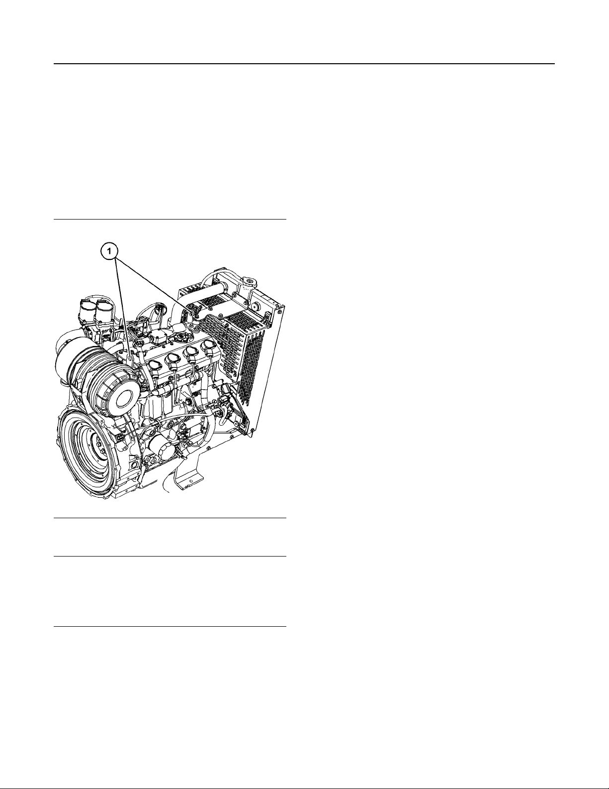
Illustration 1 g01154807
Typical example
The universe warning label (1) is on the left side of
the engine on the valve mechanism cover
Illustration 3 g00104545
Attach a “Do Not Operate” warning tag or a similar
warning tag to the start switch or to the controls
before the engine is serviced or before the engine is
repaired. Attach the warning tags to the engine and
to each operator control station. When appropriate,
disconnect the starting controls.
Do not allow unauthorized personnel on the engine,
or around the engine when the engine is being
serviced.
Page 6
6
Safety Section
General Hazard Information
SEBU9073
• Tampering with the engine installation or
tampering with the OEM supplied wiring can be
dangerous. Personal injury, death and/or engine
damage could result.
• Vent the engine exhaust to the outside when the
engine is operated in an enclosed area.
• If the engine is not running, do not release the
secondary brake or the parking brake systems
unless the vehicle is blocked or unless the vehicle
is restrained.
• Wear a hard hat, protective glasses, and other
protective equipment, as required.
• When work is performed around an engine that is
operating, wear protective devices for ears in
order to help prevent damage to hearing.
• Do not wear loose clothing or jewelry that can
snag on controls or on other parts of the engine.
• Ensure that all protective guards and all covers
are secured in place on the engine.
• Never put maintenance fluids into glass
containers. Glass containers can break.
• For initial start-up of a new engine or for starting
an engine that has been serviced, make
provisions to stop the engine if an overspeed
occurs. The stopping of the engine may be
accomplished by shutting off the fuel supply and/
or the air supply to the engine. Ensure that only
the fuel supply line is shut off. Ensure that the fuel
return line is open.
• Start the engine from the operators station (cab).
Never short across the starting motor terminals or
the batteries. This action could bypass the engine
neutral start system and/or the electrical system
could be damaged.
Engine exhaust contains products of combustion
which may be harmful to your health. Always start the
engine and operate the engine in a well ventilated
area. If the engine is in an enclosed area, vent the
engine exhaust to the outside.
Cautiously remove the following parts. To help
prevent spraying or splashing of pressurized fluids,
hold a rag over the part that is being removed.
• Filler caps
• Grease fittings
• Use all cleaning solutions with care.
• Report all necessary repairs.
Unless other instructions are provided, perform the
maintenance under the following conditions:
• The engine is stopped. Ensure that the engine
cannot be started.
• The protective locks or the controls are in the
applied position.
• Engage the secondary brakes or parking brakes.
• Block the vehicle or restrain the vehicle before
maintenance or repairs are performed.
• Disconnect the batteries when maintenance is
performed or when the electrical system is
serviced. Disconnect the battery ground leads.
Tape the leads in order to help prevent sparks.
• Do not attempt any repairs or any adjustments to
the engine while the engine is operating.
• Do not attempt any repairs that are not
understood. Use the proper tools. Replace any
equipment that is damaged or repair the
equipment.
• Pressure taps
• Breathers
• Drain plugs
Use caution when cover plates are removed.
Gradually loosen, but do not remove the last two
bolts or nuts that are located at opposite ends of the
cover plate or the device. Before removing the last
two bolts or nuts, pry the cover loose in order to
relieve any spring pressure or other pressure.
Illustration 4 g00702020
• Wear a hard hat, protective glasses, and other
protective equipment, as required.
Page 7
SEBU9073
7
Safety Section
General Hazard Information
• When work is performed around an engine that is
operating, wear protective devices for ears in
order to help prevent damage to hearing.
• Do not wear loose clothing or jewelry that can
snag on controls or on other parts of the engine.
• Ensure that all protective guards and all covers
are secured in place on the engine.
• Never put maintenance fluids into glass
containers. Glass containers can break.
• Use all cleaning solutions with care.
• Report all necessary repairs.
Unless other instructions are provided, perform
the maintenance under the following conditions:
• The engine is stopped. Ensure that the engine
cannot be started.
• Disconnect the batteries when maintenance is
performed or when the electrical system is
serviced. Disconnect the battery ground leads.
Tape the leads in order to help prevent sparks.
• Do not attempt any repairs that are not
understood. Use the proper tools. Replace any
equipment that is damaged or repair the
equipment.
The maximum air pressure for cleaning purposes
must be below 205 kPa (30 psi). The maximum
water pressure for cleaning purposes must be below
275 kPa (40 psi).
Containing Fluid Spillage
Care must be taken to ensure that fluids are
contained during performance of inspection,
maintenance, testing, adjusting, and repair of the
product. Be prepared to collect the fluid with suitable
containers before opening any compartment or
disassembling any component containing fluids.
Dispose of all fluids according to local regulations
and mandates.
Inhalation
Electrostatic Discharge
Before performing any service or repair follow the
instruction:
• Discharge the static electricity on your body to
ground by touching and holding a grounded metal
object.
Pressurized Air and Water
Pressurized air and/or water can cause debris and/or
hot water to be blown out. This action could result in
personal injury.
When pressurized air and/or pressurized water is
used for cleaning, wear protective clothing, protective
shoes, and eye protection. Eye protection includes
goggles or a protective face shield.
Illustration 5 g00702022
Exhaust
Use caution. Exhaust fumes can be hazardous to
health. If you operate the equipment in an enclosed
area, adequate ventilation is necessary.
Asbestos Information
Perkins equipment and replacement parts that are
shipped from Perkins engine company limited are
asbestos free. Perkins recommends the use of only
genuine Perkins replacement parts. Use the following
guidelines when you handle any replacement parts
that contain asbestos or when you handle asbestos
debris.
Use caution. Avoid inhaling dust that might be
generated when you handle components that contain
asbestos fibers. Inhaling this dust can be hazardous
to your health. The components that may contain
asbestos fibers are brake pads, brake bands, lining
material, clutch plates, and some gaskets. The
asbestos that is used in these components is usually
bound in a resin or sealed in some way. Normal
handling is not hazardous unless airborne dust that
contains asbestos is generated.
Page 8
8
Safety Section
Burn Prevention
SEBU9073
If dust that may contain asbestos is present, there
are several guidelines that should be followed:
• Never use compressed air for cleaning.
• Avoid brushing materials that contain asbestos.
• Avoid grinding materials that contain asbestos.
• Use a wet method in order to clean up asbestos
materials.
• A vacuum cleaner that is equipped with a high
efficiency particulate air filter (HEPA) can also be
used.
• Use exhaust ventilation on permanent machining
jobs.
• Wear an approved respirator if there is no other
way to control the dust.
• Comply with applicable rules and regulations for
the work place. In the United States, use
Occupational Safety and Health Administration
(OSHA) requirements. These OSHA requirements
can be found in “29 CFR 1910.1001”.
• Obey environmental regulations for the disposal of
asbestos.
• Stay away from areas that might have asbestos
particles in the air.
Always use leakproof containers when you drain
fluids. Do not pour waste onto the ground, down a
drain, or into any source of water.
i06149208
Burn Prevention
SMCS Code: 1000
Allow the engine system to cool before any
maintenance is performed. Relieve all pressure in the
air system, hydraulic system, lubrication system, fuel
system, and the cooling system before the related
items are disconnected.
Allow the pressure to be purged in the air system, in
the hydraulic system, in the lubrication system, or in
the cooling system before any lines, fittings, or
related items are disconnected.
Coolant
When the engine is at operating temperature, the
engine coolant is hot. The coolant is also under
pressure. The radiator and all lines to the heaters or
to the engine contain hot coolant.
Any contact with hot coolant or with steam can cause
severe burns. Allow cooling system components to
cool before the cooling system is drained.
Check that the coolant level after the engine has
stopped and the engine has been allowed to cool.
Dispose of Waste Properly
Illustration 6 g00706404
Improperly disposing of waste can threaten the
environment. Potentially harmful fluids should be
disposed of according to local regulations.
Ensure that the filler cap is cool before removing the
filler cap. The filler cap must be cool enough to touch
with a bare hand. Remove the filler cap slowly in
order to relieve pressure.
Page 9
SEBU9073
9
Safety Section
Fire Prevention and Explosion Prevention
Cooling system conditioner contains alkali. Alkali can
cause personal injury. Do not allow alkali to contact
the skin, the eyes, or the mouth.
Oils
Skin may be irritated following repeated or prolonged
exposure to mineral and synthetic base oils. Refer to
your suppliers Material Safety Data Sheets for
detailed information. Hot oil and lubricating
components can cause personal injury. Do not allow
hot oil to contact the skin. Appropriate personal
protective equipment should be used.
Batteries
Electrolyte is an acid. Electrolyte can cause personal
injury. Do not allow electrolyte to contact the skin or
the eyes. Always wear protective glasses for
servicing batteries. Wash hands after touching the
batteries and connectors. Use of gloves is
recommended.
i06149211
Fire Prevention and Explosion
Prevention
SMCS Code: 1000
Determine whether the engine will be operated in an
environment that allows combustible gases to be
drawn into the air inlet system. These gases could
cause the engine to overspeed. Personal injury,
property damage, or engine damage could result.
If the application involves the presence of
combustible gases, consult your Perkins distributor
for additional information about suitable protection
devices.
Remove all flammable combustible materials or
conductive materials such as fuel, oil, and debris
from the engine. Do not allow any flammable
combustible materials or conductive materials to
accumulate on the engine.
Store fuels and lubricants in correctly marked
containers away from unauthorized persons. Store
oily rags and any flammable materials in protective
containers. Do not smoke in areas that are used for
storing flammable materials.
Do not expose the engine to any flame.
Exhaust shields (if equipped) protect hot exhaust
components from oil or fuel line, tube, or a seal
failure. Exhaust shields must be installed correctly.
Do not weld on lines or tanks that contain flammable
fluids. Do not flame cut lines or tanks that contain
flammable fluid. Clean any such lines or tanks
thoroughly with a nonflammable solvent prior to
welding or flame cutting.
Illustration 7 g00704000
All fuels, most lubricants, and some coolant mixtures
are flammable.
Flammable fluids that are leaking or spilled onto hot
surfaces or onto electrical components can cause a
fire. Fire may cause personal injury and property
damage.
After the emergency stop button is operated, ensure
that you allow 15 minutes, before the engine covers
are removed.
Wiring must be kept in good condition. Ensure that all
electrical wires are correctly installed and securely
attached. Check all electrical wires daily. Repair any
wires that are loose or frayed before you operate the
engine. Clean all electrical connections and tighten
all electrical connections.
Eliminate all wiring that is unattached or
unnecessary. Do not use any wires or cables that are
smaller than the recommended gauge. Do not
bypass any fuses and/or circuit breakers.
Arcing or sparking could cause a fire. Secure
connections, recommended wiring, and correctly
maintained battery cables will help to prevent arcing
or sparking.
Ensure that the engine is stopped. Inspect all lines
and hoses for wear or for deterioration. Ensure that
the hoses are correctly routed. The lines and hoses
must have adequate support and secure clamps.
Oil filters and fuel filters must be installed correctly.
The filter housings must be tightened to the correct
torque. Refer to the Disassembly and Assembly
manual for more information.
Page 10
10
Safety Section
Fire Prevention and Explosion Prevention
Illustration 8 g00704059
SEBU9073
Never check the battery charge by placing a metal
object across the terminal posts. Use a voltmeter or a
hydrometer.
Incorrect jumper cable connections can cause an
explosion that can result in injury. Refer to the
Operation Section of this manual for specific
instructions.
Do not charge a frozen battery. A frozen battery may
cause an explosion.
The batteries must be kept clean. The covers (if
equipped) must be kept on the cells. Use the
recommended cables, connections, and battery box
covers when the engine is operated.
Fire Extinguisher
Make sure that a fire extinguisher is available. Be
familiar with the operation of the fire extinguisher.
Inspect the fire extinguisher and service the fire
extinguisher regularly. Obey the recommendations
on the instruction plate.
Use caution when you are refueling an engine. Do
not smoke while you are refueling an engine. Do not
refuel an engine near open flames or sparks. Always
stop the engine before refueling.
Avoid static electricity risk when fueling. Consult your
fuel or fuel system supplier to ensure that the delivery
system is in compliance with fueling standards for
proper grounding and bonding practices.
Lines, Tubes, and Hoses
Do not bend high-pressure lines. Do not strike highpressure lines. Do not install any lines that are
damaged.
Leaks can cause fires. Consult your Perkins
distributor for replacement parts.
Replace the parts if any of the following conditions
are present:
• End fittings are damaged or leaking.
• Outer coverings are chafed or cut.
• Wires are exposed.
• Outer coverings are ballooning.
• Flexible parts of the hoses are kinked.
• Outer covers have embedded armoring.
• End fittings are displaced.
Illustration 9 g00704135
Gases from a battery can explode. Keep any open
flames or sparks away from the top of a battery. Do
not smoke in battery charging areas.
Page 11
SEBU9073
11
Safety Section
Crushing Prevention and Cutting Prevention
Make sure that all clamps, guards, and heat shields
are installed correctly. During engine operation,
correct installation will help to prevent vibration,
rubbing against other parts, and excessive heat.
i06149222
Crushing Prevention and
Cutting Prevention
SMCS Code: 1000
Support the component correctly when work beneath
the component is performed.
Unless other maintenance instructions are provided,
never attempt adjustments while the engine is
running.
Stay clear of all rotating parts and of all moving parts.
Leave the guards in place until maintenance is
performed. After the maintenance is performed,
reinstall the guards.
Keep objects away from moving fan blades. The fan
blades will throw objects or cut objects.
When objects are struck, wear protective glasses in
order to avoid injury to the eyes.
Chips or other debris may fly off objects when objects
are struck. Before objects are struck, ensure that no
one will be injured by flying debris.
i06149224
Ensure that the power supply is isolated before any
service or repairs are performed.
i03560601
Before Starting Engine
SMCS Code: 1000
NOTICE
For initial start-up of a new or rebuilt engine, and for
start-up of an engine that has been serviced, make
provision to shut the engine off should an overspeed
occur. This may be accomplished by shutting off the
air and/or fuel supply to the engine.
Engine exhaust contains products of combustion
which may be harmful to your health. Always
start and operate the engine in a well ventilated
area and, if in an enclosed area, vent the exhaust
to the outside.
Inspect the engine for potential hazards.
Do not start the engine or move any of the controls if
there is a “DO NOT OPERATE” warning tag or similar
warning tag attached to the start switch or to the
controls.
Before starting the engine, ensure that no one is on,
underneath, or close to the engine. Ensure that the
area is free of personnel.
Mounting and Dismounting
SMCS Code: 1000
Do not climb on the engine . The engine has not
been designed with mounting or dismounting
locations.
Refer to the OEM for the location of foot and hand
holds for your specific application.
i06210914
Ignition Systems
SMCS Code: 1550
Ignition systems can cause electrical shocks. Avoid
contacting the ignition system components and
wiring.
If the control is in the AUTOMATIC or START position
the ignition system may discharge, and a spark plug
will operate. The spark plug will ignite any gas that
has accumulated in that cylinder. The crankshaft and
the driven equipment can move. Personal injury may
result. Gas that has accumulated in the exhaust
system can also be ignited.
If equipped, ensure that the lighting system for the
engine is suitable for the conditions. Ensure that all
lights work properly, if equipped.
All protective guards and all protective covers must
be installed if the engine must be started in order to
perform service procedures. To help prevent an
accident that is caused by parts in rotation, work
around the parts carefully.
Do not bypass the automatic shutoff circuits. Do not
disable the automatic shutoff circuits. The circuits are
provided in order to help prevent personal injury. The
circuits are also provided in order to help prevent
engine damage.
See the Service Manual for repairs and for
adjustments.
i06149227
Engine Starting
SMCS Code: 1000
If a warning tag is attached to the engine start switch,
or to the controls DO NOT start the engine or move
the controls. Consult with the person that attached
the warning tag before the engine is started.
Page 12

12
Safety Section
Engine Stopping
SEBU9073
All protective guards and all protective covers must
be installed if the engine must be started in order to
perform service procedures. To help prevent an
accident that is caused by parts in rotation, work
around the parts carefully.
Start the engine from the operators compartment or
from the engine start switch.
Always start the engine according to the procedure
that is described in the Operation and Maintenance
Manual, “Engine Starting” topic in the Operation
Section. Knowing that the correct procedure will help
to prevent major damage to the engine components.
Knowing that the procedure will also help to prevent
personal injury.
To ensure that the jacket water heater (if equipped)
and/or the lube oil heater (if equipped) is working
correctly, check the water temperature gauge. Also,
check the oil temperature gauge during the heater
operation.
Engine exhaust contains products of combustion
which can be harmful to your health. Always start the
engine and operate the engine in a well ventilated
area. If the engine is started in an enclosed area,
vent the engine exhaust to the outside.
i02234873
To help prevent sparks from igniting combustible
gases that are produced by some batteries, the
negative “−” jump start cable should be connected
last from the external power source to the negative
“−” terminal of the starting motor. If the starting motor
is not equipped with a negative “−” terminal, connect
the jump start cable to the engine block.
Check the electrical wires daily for wires that are
loose or frayed. Tighten all loose electrical wires
before the engine is started. Repair all frayed
electrical wires before the engine is started. See the
Operation and Maintenance Manual for specific
starting instructions.
Grounding Practices
Correct grounding for the engine electrical system is
necessary for optimum engine performance and
reliability. Incorrect grounding will result in
uncontrolled electrical circuit paths and in unreliable
electrical circuit paths.
Uncontrolled electrical circuit paths can result in
damage to main bearings, to crankshaft bearing
journal surfaces, and to aluminum components.
Engines that are installed without engine-to-frame
ground straps can be damaged by electrical
discharge.
Engine Stopping
SMCS Code: 1000
Stop the engine according to the procedure in the
Operation and Maintenance Manual, “Engine
Stopping (Operation Section)” in order to avoid
overheating of the engine and accelerated wear of
the engine components.
Use the Emergency Stop Button (if equipped) ONLY
in an emergency situation. Do not use the
Emergency Stop Button for normal engine stopping.
After an emergency stop, DO NOT start the engine
until the problem that caused the emergency stop
has been corrected.
Stop the engine if an overspeed condition occurs
during the initial start-up of a new engine or an
engine that has been overhauled.
To stop an electronically controlled engine, cut the
power to the engine and/or shutting off the air supply
to the engine.
i02176668
Electrical System
SMCS Code: 1000; 1400
To ensure that the engine and the engine electrical
systems function correctly, an engine-to-frame
ground strap with a direct path to the battery must be
used. This path may be provided by way of a direct
engine ground to the frame.
All grounds should be tight and free of corrosion. The
engine alternator must be grounded to the negative
“-” battery terminal with a wire that is adequate to
handle the full charging current of the alternator.
Never disconnect any charging unit circuit or battery
circuit cable from the battery when the charging unit
is operating. A spark can cause the combustible
gases that are produced by some batteries to ignite.
Page 13
SEBU9073
Product Information
Section
Model Views and
Specifications
i06198554
Model View Illustrations
SMCS Code: 1000
The following model views show typical features of
the engine. Due to individual applications, your
engine may appear different from the illustrations.
13
Product Information Section
Model Views and Specifications
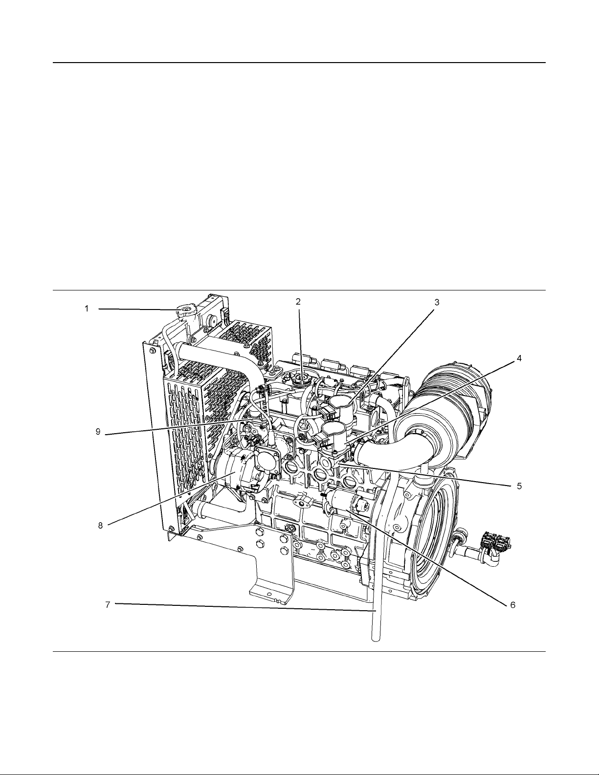
Illustration 10 g03848732
Typical example
(1) Coolant filler pressure cap
(2) Top oil filler cap
(3) Control throttle
(4) Control
(5) Mixer
(6) Starting motor
(7) Breather outlet hose
(8) Alternator
(9) Thermostat housing
Page 14
14
Product Information Section
Product Description
SEBU9073
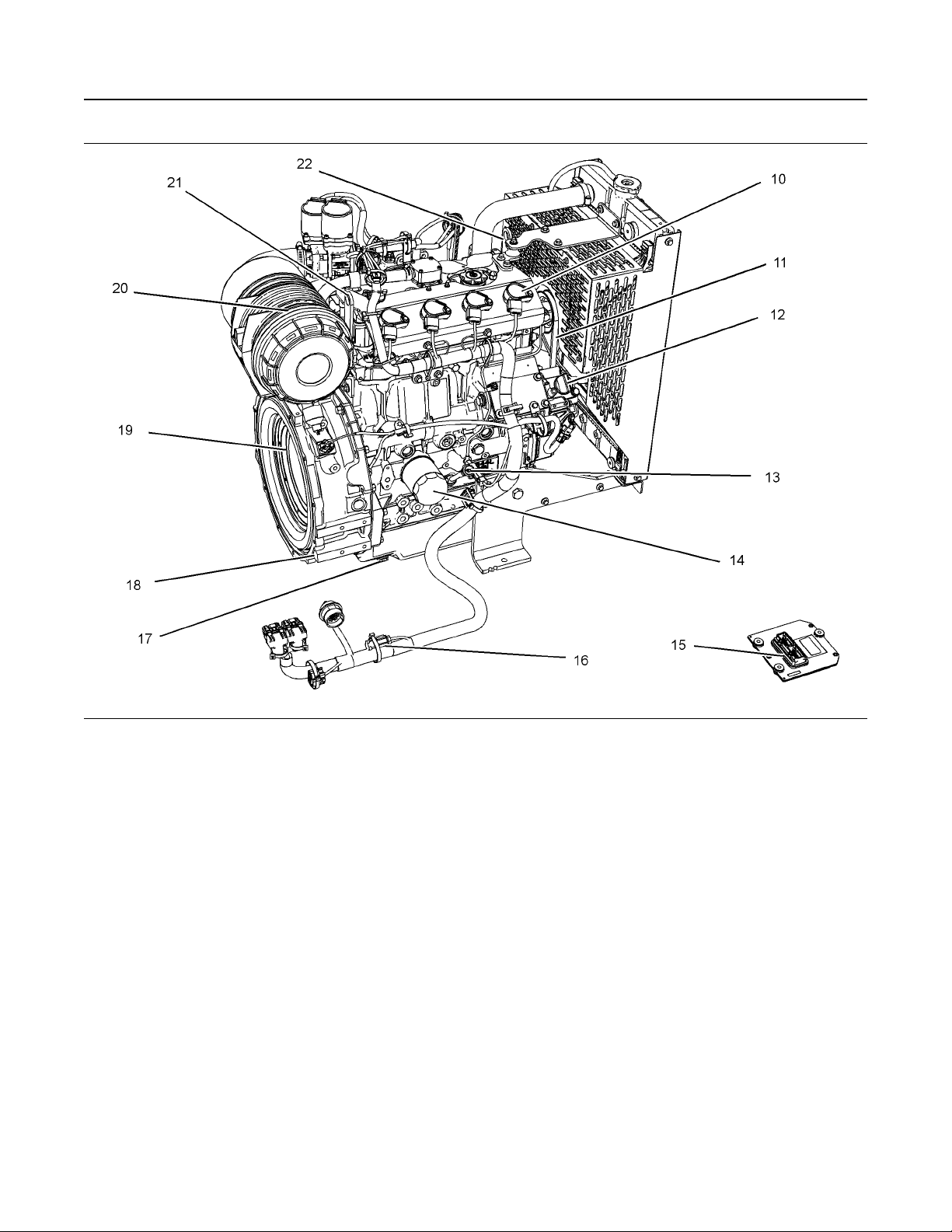
Illustration 11 g03848772
Typical example
(10) Ignition coil
(11) Fan belt
(12) Lower oil filler
(13) Oil gauge (Dipstick)
(14) Oil filter
(15) Electronic control module
(16) Wiring harness
(17) Oil drain plug
(18) Flywheel housing
(19) Flywheel
i06149296
• Valve Lash Setting (Exhaust) 0.20 mm
(20) Air cleaner
(21) Engine rear lifting eye
(22) Engine front lifting eye
(0.00787 inch)
Product Description
• Compression Ratio 9: 1
SMCS Code: 1000; 4450; 4491
• Firing Order 1-3-4-2
The Perkins 404A-22SG1 is a gas fueled constant
speed industrial engine.
• RPM 1500/1800
The 404A-22SG1 has the following characteristics:
• In-line four cylinder
• Two valves per cylinder
• Four stroke cycle
• Valve Lash Setting (Inlet) 0.20 mm (0.00787 inch)
Page 15
SEBU9073
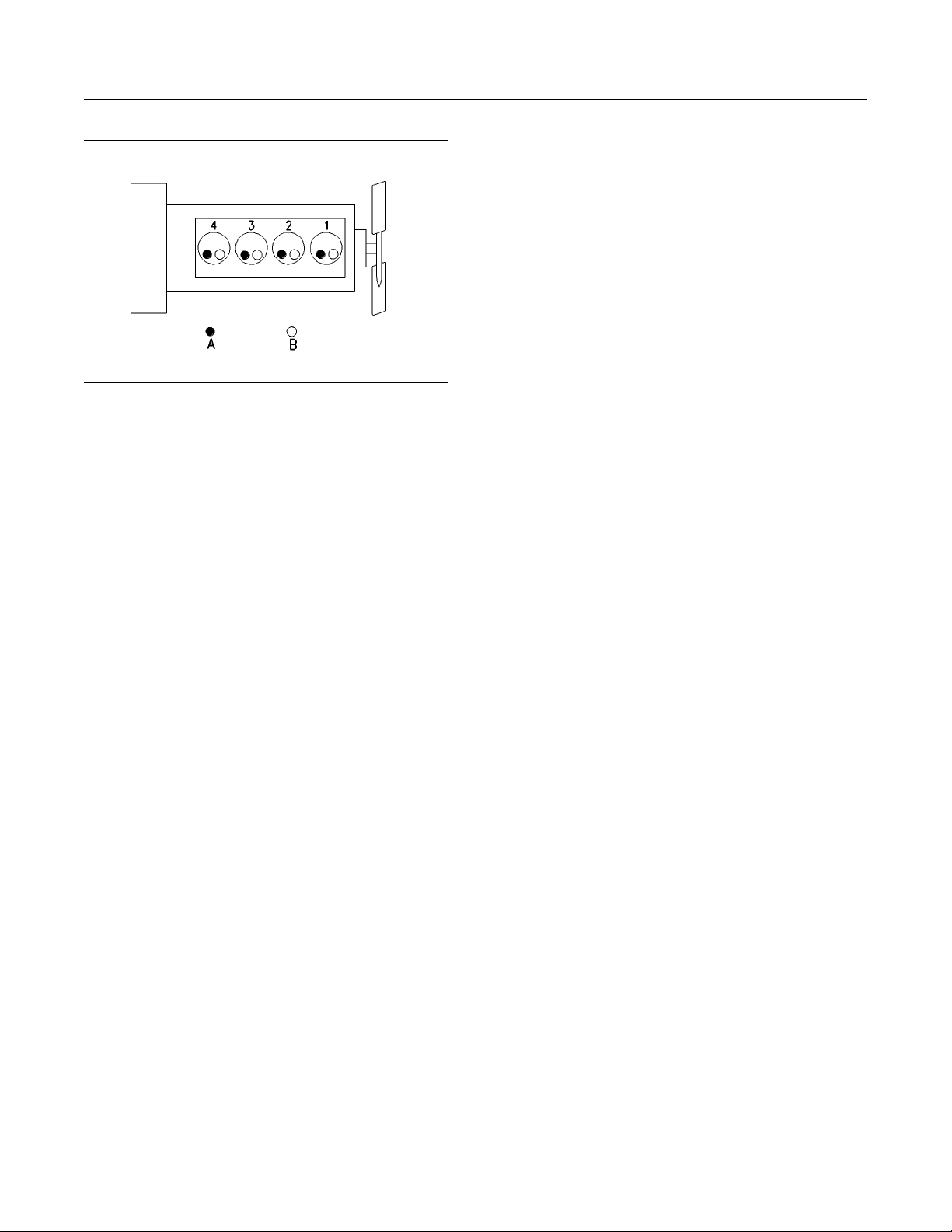
Illustration 12 g00296424
(A) Exhaust valves
(B) Inlet valves
The front end of the engine is opposite the flywheel
end of the engine. The left and the right side of the
engine is determined from the flywheel end. The No.
1 cylinder is the front cylinder.
15
Product Information Section
Product Description
When auxiliary devices, accessories, or
consumables (filters, additives, catalysts,) which are
made by other manufacturers are used on Perkins
products, the Perkins warranty is not affected simply
because of such use.
However, failures that result from the installation or
use of other manufacturers devices, accessories, or
consumables are NOT Perkins defects. Therefore,
the defects are NOT covered under the Perkins
warranty.
Ignition System
• ECM
• 4 Ignition coils
• Crankshaft position sensor and camshaft position
sensor
• Spark Plug
Gas System
• Fuel filter
• Electric fuel vapor lock off solenoid valve
• Fuel pressure regulator
• Fuel trim valve
• Gas/air mixer
Engine Service Life
Engine efficiency and maximum utilization of engine
performance depend on the adherence to proper
operation and maintenance recommendations. In
addition, use recommended fuels, coolants, and
lubricants. Use the Operation and Maintenance
Manual as a guide for required engine maintenance.
Aftermarket Products and Perkins
Engines
Perkins does not warrant the quality or performance
of non-Perkins fluids and filters.
Page 16
16
Product Information Section
Product Identification Information
SEBU9073
Product Identification
Information
Plate Locations and Film
Locations
SMCS Code: 1000; 4450
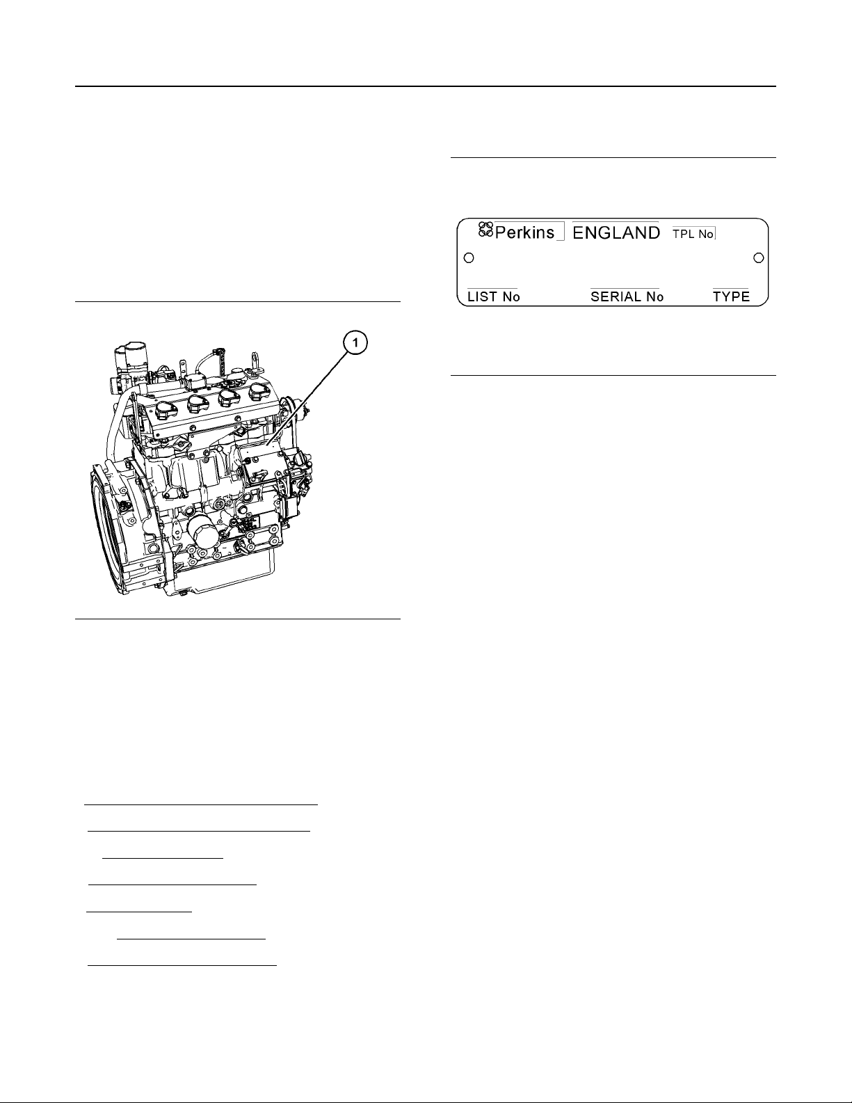
Serial Number Plate
i06156142
Illustration 14 g01094203
Typical example
Illustration 13 g03831850
Typical example
(1) Engine serial plate location
Perkins engines are identified by a serial number.
This number is shown on a serial number plate that is
mounted above the fuel injection pump on the righthand side of the engine block.
An example of an engine number is
EX*****U000001A.
E Engine family
X Type of engine
***** The list number of the engine
U Country of manufacture
0 The first digit is a production code.
00001 Engine Serial Number
A Year of Manufacture
Perkins dealers or Perkins distributors need all these
numbers to determine the components that were
included with the engine. This information permits
accurate identification of replacement part numbers.
Page 17
SEBU9073
17
Operation Section
Lifting and Storage
Operation Section
Lifting and Storage
Product Lifting
SMCS Code: 1000; 7002
i06205337
Lifting eyes are designed and installed for specific
engine arrangements. Alterations to the lifting eyes
and/or the engine make the lifting eyes and the lifting
fixtures obsolete. If alterations are made, ensure that
correct lifting devices are provided. Consult your
Perkins distributor for information regarding fixtures
for correct engine lifting.
i06152951
Product Storage
SMCS Code: 1000; 7002
Perkins are not responsible for damage which may
occur when an engine is in storage after a period in
service.
Your Perkins distributor can assist in preparing the
engine for extended storage periods.
Condition for Storage
The engine must be stored in a water proof building.
The building must be kept at a constant temperature.
Engines that are filled with Perkins ELC will have
coolant protection to an ambient temperature of
−36° C (−32.8° F). The engine must not be subjected
to extreme variations in temperature and humidity.
Illustration 15 g03851874
Typical example
NOTICE
Never bend the eyebolts and the brackets. Only load
the eyebolts and the brackets under tension. Remember that the capacity of an eyebolt is less as the
angle between the supporting members and the object becomes less than 90 degrees.
Use a hoist to remove heavy components. Use an
adjustable lifting beam to lift the engine. All
supporting members (chains and cables) should be
parallel to each other. The chains and cables should
be perpendicular to the top of the object that is being
lifted.
The lifting eyes should be used to lift only the engine
and radiator as supplied by Perkins.
Storage Period
An engine can be stored for up to 6 months provided
all the recommendation are adhered to.
Storage Procedure
Keep a record of the procedure that has been
completed on the engine.
1. Ensure that the engine is clean and dry.
2. Ensure that all open ports on the fuel system are
capped so that no ingress of fluid or dirt can enter
the fuel system.
3. The engine oil will not need to be drained in order
to store the engine. Provided the correct
specification of engine oil is used the engine can
be stored for up to 6 months. For the correct
specification of engine oil refer to this Operation
and Maintenance Manual, “Fluid
recommendations”.
4. Remove the drive belts from the engine.
Sealed Coolant System
Ensure that the cooling system is filled with Perkins
ELC, or an antifreeze that meets “ASTM D6210”
specification.
Page 18

18
Operation Section
Product Storage
Open Cooling System
Ensure that all cooling drain plugs have been
opened. Allow the coolant to drain. Install the drain
plugs. Place a vapor phase inhibitor into the system.
The coolant system must be sealed once the vapor
phase inhibitor has been introduced. The effect of the
vapor phase inhibitor will be lost if the cooling system
is open to the atmosphere.
For maintenance procedures ref to this Operation
and Maintenance Manual.
Monthly Checks
The crankshaft must be rotated in order to change
the spring loading on the valve train. Rotate the
crankshaft more than 180 degrees. Visibly check for
damage or corrosion to the engine.
SEBU9073
Page 19

SEBU9073
19
Operation Section
Gauges and Indicators
Gauges and Indicators
i06151034
Gauges and Indicators
SMCS Code: 7450
Your engine may not have the same gauges or all the
gauges that are described. For more information
about the gauge package, see the OEM information.
Gauges provide indications of engine performance.
Ensure that the gauges are in good working order.
Determine the normal operating range by observing
the gauges over a period of time.
Noticeable changes in gauge readings indicate
potential gauge or engine problems. Problems may
also be indicated by gauge readings that change
even if the readings are within specifications.
Determine and correct the cause of any significant
change in the readings. Consult your Perkins
distributor for assistance.
NOTICE
If no oil pressure is indicated, STOP the engine. If
maximum coolant temperature is exceeded, STOP
the engine. Engine damage can result.
2. Inspect the cooling system for leaks.
3. Determine if the engine must be shutdown
immediately or if the engine can be cooled by
reducing the load.
The engine system is equipped with a warning
indicator. The light will illuminate or flash to indicate a
warning.
i06211154
Diagnostic Lamp
SMCS Code: 1000; 1900; 1901; 1902; 7451
A diagnostic lamp is used to indicate the existence of
an active fault. A fault diagnostic code will remain
active until the problem is repaired. Refer to
Troubleshooting manual for more information.
Engine Oil Pressure – The oil pressure
should be greatest after a cold engine is
started. The typical engine oil pressure
with SAE10W30 is 207 kPa to 413 kPa
(30 psi to 60 psi) at rated rpm.
A lower oil pressure is normal at low idle. If the load is
stable and the gauge reading changes, perform the
following procedure:
1. Remove the load.
2. Stop the engine
3. Check and maintain the oil level. If necessary,
determine the reason why the oil level is low.
Jacket Water Coolant Temperature –
Typical temperature range is
71°C to 96°C (160°F to 205°F). The
maximum allowable temperature with the
pressurized cooling system at 90 kPa (13 psi) is
112° C (233.6° F). Higher temperatures may occur
under certain conditions. The water temperature
reading may vary according to load. The reading
should never exceed the boiling point for the
pressurized system that is being used.
If the engine is operating above the normal range
and steam becomes apparent, perform the following
procedure:
1. Reduce the load and the engine rpm.
Page 20

20
Operation Section
Features and Controls
Features and Controls
i06151051
Sensors and Electrical
Components
SMCS Code: 1900; 7400
The engine is equipped with the following sensors or
switches:
• Coolant temperature switch
• Temperature and Manifold Air Pressure (TMAP)
sensor
• Camshaft position sensor
• Crankshaft position sensor/Flywheel
• Heated Exhaust Gas Oxygen (HEGO) sensor
SEBU9073
• Oil pressure switch
The engine is equipped with the following electrical
components:
• Shut off solenoid valve
• Control throttle (mixer)
• Control (Trim valve)
• Ignition coils
• Spark plug
• ECM
• Alternator
• Starting motor
Page 21

SEBU9073
21
Operation Section
Sensors and Electrical Components
Illustration 16 g03849448
Typical example
(1) Coolant temperature sensor
(2) Temperature and Manifold Air Pressure
(TMAP) sensor
(3) Control throttle (mixer)
(4) Control
(5) Heated Exhaust Gas Oxygen (HEGO)
sensor
(6) Starting motor
(7) Alternator
(8) Electronic control module
Page 22

22
Operation Section
Alarms and Shutoffs
SEBU9073
Illustration 17 g03849450
Typical example
(9) Ignition coil
(10) Camshaft speed/timing sensor
Alarms and Shutoffs
SMCS Code: 7400
Shutoffs
The shutoff is electrically controlled, and
mechanically operated. The mechanically operated
shutoff is controlled by the Electronic Control Module
(ECM).
(11) Oil pressure sensor (12) Crankshaft speed/timing sensor (
i06157535
• Heated Exhaust Gas Oxygen (HEGO) sensor
These sensors are connected to the ECM and will
signal the ECM. The ECM will send a signal in order
to illuminate the lamp, if action is required.
Flywheel)l
i06157531
Control Panel
SMCS Code: 7451
For information on the control panel installed, refer to
the OEM instructions.
Alarms
The engine is equipped with the following sensors:
• Crankshaft position sensor
• Camshaft position sensor
• Oil pressure switch
• Temperature and Manifold Air Pressure (TMAP)
sensor
• Coolant temperature sensor
Page 23

SEBU9073
23
Operation Section
Engine Starting
Engine Starting
i06157532
Before Starting Engine
SMCS Code: 1000
Before the engine is started, perform the required
daily maintenance and any other periodic
maintenance that is due. Refer to the Operation and
Maintenance Manual, “Maintenance Interval
Schedule” for more information.
• For the maximum service life of the engine, make
a thorough inspection within the engine
compartment before the engine is started. Look for
the following items: oil leaks, coolant leaks, loose
bolts and excessive dirt and/or grease. Remove
any excess dirt and/or grease buildup. Repair any
faults that were identified during the inspection.
• Inspect the cooling system hoses for cracks and
for loose clamps.
• Inspect the alternator and accessory drive belts for
cracks, breaks, and other damage.
• Reset all of the shutoffs or alarm components (if
equipped).
• Check the engine lubrication oil level. Maintain the
oil level between the “ADD” mark and the “FULL”
mark on the engine oil level gauge.
• Check the coolant level. Observe the coolant level
in the header tank (if equipped). Maintain the
coolant level to the “FULL” mark on the header
tank.
• If the engine is not equipped with a header tank,
maintain the coolant level within 13 mm (0.5 inch)
of the bottom of the filler pipe. If the engine is
equipped with a sight glass, maintain the coolant
level in the sight glass.
• Observe the air cleaner service indicator (if
equipped). Service the air cleaner when the yellow
diaphragm enters the red zone, or when the red
piston locks in the visible position.
• Ensure that any equipment that is driven by the
engine has been disengaged from the engine.
Minimize electrical loads or remove any electrical
loads.
• Inspect the wiring for loose connections and for
worn wires or frayed wires.
• Check the fuel supply. Ensure that the fuel supply
valve is open.
Engine exhaust contains products of combustion
which may be harmful to your health. Always
start and operate the engine in a well ventilated
area and, if in an enclosed area, vent the exhaust
to the outside.
• Do not start the engine or move any of the controls
if there is a “DO NOT OPERATE” warning tag or
similar warning tag attached to the start switch or
to the controls.
• Ensure that the areas around the rotating parts are
clear.
• All of the guards must be put in place. Check for
damaged guards or for missing guards. Repair
any damaged guards. Replace damaged guards
and/or missing guards.
i06160445
Starting the Engine
SMCS Code: 1000
Engine exhaust contains products of combustion
which may be harmful to your health. Always
start and operate the engine in a well ventilated
area and, if in an enclosed area, vent the exhaust
to the outside.
Unburned gas in the air inlet and exhaust system
may ignite when the engine is started. Personal
injury and/or property damage may result.
Before starting an engine that may contain unburned gas, purge the unburned gas from the air
inlet and exhaust system. Refer to the topic on
purging unburned gas in the ““Starting the Engine””
section.
• Disconnect any battery chargers that are not
protected against the high current drain that is
created when the electric starting motor is
engaged. Check electrical cables and check the
battery for poor connections and for corrosion.
For initial start-up of a new or rebuilt engine, and for
NOTICE
start-up of an engine that has been serviced, make
provision to shut the engine off should an overspeed
occur. This may be accomplished by shutting off the
fuel supply and/or the ignition to the engine.
Page 24

24
Operation Section
Starting the Engine
SEBU9073
First Engine Start
Note: The fuel system must comply with all local
regulations.
1. The starting and the stopping of the engine must
be on no load.
2. Ensure that the starting procedure and stopping
procedure are understood before starting the
engine. If necessary, select the desired engine
speed. Refer to OEM for the correct procedure to
select the engine speed.
3. Start the engine and allow the engine to run at the
desired speed for 10 minutes.
4. Operate the engine under normal working
conditions. Check the gauges and lamps to see
the condition of the engine. If a diagnostic lamp is
active, stop the engine and investigator flash code.
For a full explanation for the flash codes, refer to
Troubleshooting for more information.
5. If the engine fails to start after two attempts,
manually turn off the gas supply and investigate
the cause. Purge the unburned gas then, refer to
Troubleshooting for more information.
Purging Unburned Gas
The following events cause unburned gas to remain
in the air inlet and in the exhaust manifold:
• Emergency stop
• Engine overspeed
• Unsuccessful successive attempts to start the
engine
Unburned gas may remain in the air inlet and exhaust
system after several unsuccessful attempts to start
the engine. The unburned gas may increase to a
concentration that may ignite during a successive
attempt to start the engine.
1. Disengage any equipment that is driven by the
engine.
2. Ensure that there is an adequate supply of fuel in
the fuel tank. Ensure that the gas supply valve is in
the ON position. Turn the keyswitch to the ON
position.
3. Check the control panel for the correct operation of
the indicator lamps. The diagnostic lamp should
illuminate for a few seconds and then be
extinguished. If the lamp does not extinguish or
does not illuminate investigator the issue
immediately, refer to Troubleshooting, “Engine
Cranks But Will Not Start” for more information.
The other indicator lamps should stay illuminated
until the engine starts and then be extinguished. If
the indicator lamps do not illuminate, and then be
extinguished after the engine starts, investigator
the issue immediately.
4. Turn keyswitch to start position and allow the
engine to crank.
NOTICE
Do not engage the starting motor when flywheel is
turning. Do not start the engine under load.
If the engine fails to start within 30 seconds, release
the starter switch or button and wait two minutes to
allow the starting motor to cool before attempting to
start the engine again.
5. Allow the keyswitch to the return to the RUN
position after the engine has started.
6. If the engine will not start, repeat steps 1 through
to step 5. After repeat attempts to start the engine,
perform (Purging Unburned Gas) procedure.
Refer to this Operation and Maintenance Manual,
“After Starting Engine”Operation and Maintenance
Manual, “Engine Operation” for more information.
Perform the following procedure to purge the
unburned gas:
1. Turn the manual gas shutoff valve to the CLOSED
position. refer to OEM information for the location
of the valve.
2. Start the engine and crank the engine for 20
seconds. Stop the engine cranking.
3. Refer to the Troubleshooting for more information.
Starting the Engine
Refer to the OEM manual for your type of controls.
Page 25

SEBU9073
25
Operation Section
Starting with Jump Start Cables
If the engine will not start, refer to Troubleshooting,
“Engine Cranks But Will Not Start”.
i06157533
Starting with Jump Start
Cables
(Do Not Use This Procedure in
Hazardous Locations that have
Explosive Atmospheres)
SMCS Code: 1000; 1401; 1402
Improper jump start cable connections can cause
an explosion resulting in personal injury.
Prevent sparks near the batteries. Sparks could
cause vapors to explode. Do not allow jump start
cable ends to contact each other or the engine.
Note: If possible, first diagnose the reason for the
starting failure. Make any necessary repairs. If the
engine will not start only due to the condition of the
battery, either charge the battery, or start the engine
with jump-start cables. The condition of the battery
can be rechecked after the engine has been switched
OFF.
NOTICE
Using a battery source with the same voltage as the
electric starting motor. Use ONLY equal voltage for
jump starting. The use of higher voltage will damage
the electrical system.
Do not reverse the battery cables. The alternator can
be damaged. Attach ground cable last and remove
first.
When using an external electrical source to start the
engine, turn the generator set control switch to the
“OFF” position. Turn all electrical accessories OFF
before attaching the jump start cables.
3. Connect one negative end of the jump-start cable
to the negative cable terminal of the electrical
source. Connect the other negative end of the
jump-start cable to the engine block or to the
chassis ground. This procedure helps to prevent
potential sparks from igniting the combustible
gases that are produced by some batteries.
Note: Before starting engine, ensure that the ECM
and control panel have power. Check control panel
for issues.
4. Start the engine.
5. Immediately after the stalled engine is started,
disconnect the jump-start cables in reverse order.
After jump starting, the alternator may not be able to
recharge fully batteries that are severely discharged.
The batteries must be replaced or charged to the
correct voltage with a battery charger after the engine
is stopped. Many batteries which are considered
unusable are still rechargeable. Refer to Operation
and Maintenance Manual, “Battery - Replace” and
Testing and Adjusting Manual, “Battery - Test”.
i06160415
After Starting Engine
SMCS Code: 1000
Operate the engine with out load.
• Visible check for fluid or gas leaks
• Check all gauges for normal operation
Note: Gauge readings should be observed and the
data should be recorded frequently while the engine
is operating. Comparing the data over time will help
to determine normal readings for each gauge.
Comparing data over time will also help detect
abnormal operating developments. Significant
changes in the readings should be investigated.
Ensure that the main power switch is in the OFF position before attaching the jump start cables to the engine being started.
1. Turn the start switch to the OFF position. Turn off
all the engines accessories.
2. Connect one positive end of the jump-start cable to
the positive cable terminal of the discharged
battery. Connect the other positive end of the
jump-start cable to the positive cable terminal of
the electrical source.
Page 26

26
Operation Section
Engine Operation
Engine Operation
i06157540
Engine Operation
SMCS Code: 1000
Correct operation and maintenance are key factors in
obtaining the maximum life and economy of the
engine. If the directions in the Operation and
Maintenance Manual are followed, costs can be
minimized and engine service life can be maximized.
For constant speed engines, allow the engine to
operate without load in order to warm the engine
before applying load.
Gauge readings should be observed and the data
should be recorded frequently while the engine is
operating. Comparing the data over time will help to
determine normal readings for each gauge.
Comparing data over time will also help detect
abnormal operating developments. Significant
changes in the readings should be investigated.
SEBU9073
Page 27

SEBU9073
27
Operation Section
Engine Stopping
Engine Stopping
i05955161
Emergency Stopping
SMCS Code: 1000
NOTICE
Emergency shutoff controls are for EMERGENCY
use ONLY. DO NOT use emergency shutoff devices
or controls for normal stopping procedure.
The OEM may have equipped the application with an
emergency stop button. For more information about
the emergency stop button, refer to the OEM
information.
Ensure that any components for the external system
that support the engine operation are secured after
the engine is stopped.
i05955160
Manual Stop Procedure
SMCS Code: 1000
2. Stop the engine after the cool down period
according to the shutoff system on the engine and
turn the ignition keyswitch to the OFF position. If
necessary, refer to the instructions that are
provided by the OEM.
i06157539
After Stopping Engine
SMCS Code: 1000
Note: Before you check the engine oil, do not
operate the engine for at least 10 minutes in order to
allow the engine oil to return to the oil pan.
• Check the crankcase oil level. Maintain the oil
level between the “MIN” mark and the “MAX” mark
on the oil level dipstick.
• If necessary, perform minor adjustments. Repair
any leaks and tighten any loose bolts.
• Note the required service interval. Perform the
maintenance that is in the Operation and
Maintenance Manual, “Maintenance Interval
Schedule”.
Stopping the Engine
NOTICE
Stopping the engine immediately after it has been
working under load, can result in overheating and accelerated wear of the engine components.
Avoid accelerating the engine prior to shutting it
down.
Avoiding hot engine shutdowns will maximize turbocharger shaft and bearing life.
Note: Individual applications will have different
control systems. Ensure that the shutoff procedures
are understood. Use the following general guidelines
in order to stop the engine.
1. Remove the load from the engine. Allow the
engine to run under no load conditions for 5
minutes in order to cool the engine.
• Check fuel level.
NOTICE
Only use antifreeze/coolant mixtures recommended
in this Operation and Maintenance Manual, “Refill
Capacities and Recommendations” topic or in this
Operation and Maintenance Manual, “Fluid Recommendations” topic. Failure to do so can cause engine
damage.
• Allow the engine to cool. Check the coolant level.
• If freezing temperatures are expected, check the
coolant for the correct antifreeze protection. The
cooling system must be protected against freezing
to the lowest expected outside temperature. Add
the correct coolant/water mixture, if necessary.
• Perform all required periodic maintenance on all
driven equipment. This maintenance is outlined in
the instructions from the OEM.
Page 28

28
Maintenance Section
Refill Capacities
SEBU9073
Maintenance Section
Refill Capacities
i06207180
Fluid Recommendations
SMCS Code: 1280; 1348; 1395; 7560
General Coolant Information
NOTICE
Never add coolant to an overheated engine. Engine
damage could result. Allow the engine to cool first.
NOTICE
If the engine is to be stored in, or shipped to an area
with below freezing temperatures, the cooling system
must be either protected to the lowest outside temperature or drained completely to prevent damage.
NOTICE
Frequently check the specific gravity of the coolant
for proper freeze protection or for anti-boil protection.
Clean the cooling system for the following reasons:
• Contamination of the cooling system
• Overheating of the engine
• Foaming of the coolant
NOTICE
Never operate an engine without water temperature
regulators in the cooling system. Water temperature
regulators help to maintain the engine coolant at the
proper operating temperature. Cooling system problems can develop without water temperature
regulators.
Water
Water is used in the cooling system in order to
transfer heat.
Distilled water or deionized water is
recommended for use in engine cooling systems.
DO NOT use the following types of water in cooling
systems: Hard water, softened water that has been
conditioned with salt and sea water.
If distilled water or deionized water is not available,
use water with the properties that are listed in Table 1
.
Table 1
Acceptable Water
Property
Chloride (Cl) 40 mg/L
Sulfate (SO
Total Hardness
Total Solids
Acidity pH of 5.5 to 9.0
) 100 mg/L
4
Maximum Limit
170 mg/L
340 mg/L
For a water analysis, consult one of the following
sources:
• Local water utility company
• Agricultural agent
• Independent laboratory
Additives
Additives help to protect the metal surfaces of the
cooling system. A lack of coolant additives or
insufficient amounts of additives enable the following
conditions to occur:
• Corrosion
• Formation of mineral deposits
Many engine failures are related to the cooling
system. The following problems are related to cooling
system failures: Overheating, leakage of the water
pump and plugged radiators or heat exchangers.
These failures can be avoided with correct cooling
system maintenance. Cooling system maintenance is
as important as maintenance of the fuel system and
the lubrication system. Quality of the coolant is as
important as the quality of the fuel and the lubricating
oil.
Coolant is normally composed of three elements:
Water, additives and glycol.
• Rust
• Scale
• Foaming of the coolant
Many additives are depleted during engine operation.
These additives must be replaced periodically.
Additives must be added at the correct concentration.
Over concentration of additives can cause the
inhibitors to drop out-of-solution. The deposits can
enable the following problems to occur:
• Formation of gel compounds
• Reduction of heat transfer
Page 29

SEBU9073
29
Maintenance Section
Fluid Recommendations
• Leakage of the water pump seal
• Plugging of radiators, coolers, and small passages
Glycol
Glycol in the coolant helps to provide protection
against the following conditions:
• Boiling
• Freezing
• Cavitation of the water pump
For optimum performance, Perkins recommends a
1:1 mixture of a water/glycol solution.
Note: Use a mixture that will provide protection
against the lowest ambient temperature.
Note: 100 percent pure glycol will freeze at a
temperature of −13 °C (8.6 °F).
Most conventional antifreezes use ethylene glycol.
Propylene glycol may also be used. In a 1:1 mixture
with water, ethylene and propylene glycol provide
similar protection against freezing and boiling. Refer
to Table 2 and refer to table 3 .
Table 2
Ethylene Glycol
Concentration Freeze Protection
50 Percent
60 Percent
NOTICE
Do not use propylene glycol in concentrations that
exceed 50 percent glycol because of the reduced
heat transfer capability of propylene glycol. Use ethylene glycol in conditions that require additional protection against boiling or freezing.
Table 3
Propylene Glycol
Concentration Freeze Protection
50 Percent
−36 °C (−33 °F)
−51 °C (−60 °F)
−29 °C (−20 °F)
The following two coolants are used in Perkins
engines:
Preferred – Perkins ELC
Acceptable – A commercial heavy-duty antifreeze
that meets “ASTM D6210 ” specifications
NOTICE
The 404A-22SG1 industrial engines must be
operated with a 1:1 mixture of water and glycol.
NOTICE
Do not use a commercial coolant/antifreeze that only
meets the ASTM D3306 specification. This type of
coolant/antifreeze is made for light automotive
applications.
Perkins recommends a 1:1 mixture of water and
glycol. This mixture of water and glycol will provide
optimum heavy-duty performance as an antifreeze.
This ratio may be increased to 1:2 water to glycol if
extra freezing protection is required.
A mixture of SCA inhibitor and water is acceptable
but will not give the same level of corrosion, boiling
and, freezing protection as ELC. Perkins
recommends a 6 percent to 8 percent concentration
of SCA in those cooling systems. Distilled water or
deionized water is preferred. Standard required
ASTM D1384, D2570, and D4340
Table 4
Coolant Service Life
Coolant Type
Perkins ELC
Commercial Heavy-Duty Anti-
freeze that meets “ASTM
Commercial SCA inhibitor and
(1)
Use the interval that occurs first. The cooling system must also
be flushed out at this time.
D6210”
Water
3000 Service Hours or Two Year
3000 Service Hours or One Year
Service Life
6,000 Service Hours or Three
(1)
Years
ELC
To check the concentration of glycol in the coolant,
measure the specific gravity of the coolant.
Coolant Recommendations
• ELC Extended Life Coolant
• SCA Supplement Coolant Additive
• ASTM American Society for Testing and
Materials
Perkins provides ELC for use in the following
applications:
• Heavy-duty spark ignited gas engines
Page 30

30
Maintenance Section
Fluid Recommendations
SEBU9073
The anti-corrosion package for ELC is different from
the anti-corrosion package for other coolants. ELC is
an ethylene glycol base coolant. However, ELC
contains organic corrosion inhibitors and antifoam
agents with low amounts of nitrite. Perkins ELC has
been formulated with the correct amount of these
additives in order to provide superior corrosion
protection for all metals in engine cooling systems.
ELC is available in a premixed cooling solution with
distilled water. ELC is a 1:1 mixture. The Premixed
ELC provides freeze protection to −36 °C (−33 °F).
The Premixed ELC is recommended for the initial fill
of the cooling system. The Premixed ELC is also
recommended for topping off the cooling system.
Containers of several sizes are available. Consult
your Perkins distributor for the part numbers.
ELC Cooling System Maintenance
Correct additions to the Extended Life
Coolant
NOTICE
Use only Perkins products for pre-mixed or concentrated coolants.
Mixing Extended Life Coolant with other products reduces the Extended Life Coolant service life. Failure
to follow the recommendations can reduce cooling
system components life unless appropriate corrective
action is performed.
In order to maintain the correct balance between the
antifreeze and the additives, you must maintain the
recommended concentration of ELC. Lowering the
proportion of antifreeze lowers the proportion of
additive. This change will lower the ability of the
coolant to protect the system from pitting, from
cavitation, from erosion, and from deposits.
NOTICE
Do not use a conventional coolant to top-off a cooling
system that is filled with Extended Life Coolant
(ELC).
Do not use standard supplemental coolant additive
(SCA).
When using Perkins ELC, do not use standard SCA's
or SCA filters.
ELC Cooling System Cleaning
Clean water is the only cleaning agent that is
required when ELC is drained from the cooling
system.
Before the cooling system is filled, the heater control
(if equipped) must be set to the HOT position. Refer
to the OEM in order to set the heater control. After
the cooling system is drained and the cooling system
is refilled, operate the engine until the coolant level
reaches the normal operating temperature and until
the coolant level stabilizes. As needed, add the
coolant mixture in order to fill the system to the
specified level.
Changing to Perkins ELC
To change from heavy-duty antifreeze to the Perkins
ELC, perform the following steps:
NOTICE
Care must be taken to ensure that all fluids are contained during performance of inspection, mainte-
nance, testing, adjusting and the repair of the
product. Be prepared to collect the fluid with suitable
containers before opening any compartment or disassembling any component containing fluids.
Dispose of all fluids according to local regulations
and mandates.
1. Drain the coolant into a suitable container.
2. Dispose of the coolant according to local
regulations.
3. Fill the cooling system with distilled or deionized
water and operate the engine until the engine is
warmed to 49° to 66°C (120° to 150°F).
4. Fill the cooling system with a 33 percent solution of
Perkins ELC and operate the engine, ensure that
the thermostat opens. Stop the engine and allow
the engine to cool. Drain the coolant.
5. Again, fill the cooling system with a 33 percent
solution of Perkins ELC and operate the engine
ensure that the thermostat opens. Stop the engine
and allow to cool.
6. Drain the drain the cooling system.
NOTICE
Incorrect or incomplete flushing of the cooling system
can result in damage to copper and other metal
components.
Note: If the cooling system is already using ELC,
cleaning agents are not required to be used at the
specified coolant change interval. Cleaning agents
are only required if the system has been
contaminated by the addition of some other type of
coolant or by cooling system damage.
7. Fill the cooling system with the Perkins Premixed
ELC. Operate the engine. Ensure that all coolant
valves open then stop the engine. When cool
check the coolant level.
Page 31

SEBU9073
31
Maintenance Section
Fluid Recommendations
ELC Cooling System Contamination
NOTICE
Mixing ELC with other products reduces the effectiveness of the ELC and shortens the ELC service life.
Use only Perkins Products for premixed or concentrate coolants. Failure to follow these recommenda-
tions can result in shortened cooling system
component life.
ELC cooling systems can withstand contamination to
a maximum of 10 percent of conventional heavy-duty
antifreeze or SCA. If the contamination exceeds 10
percent of the total system capacity, perform ONE of
the following procedures:
• Drain the cooling system into a suitable container.
Dispose of the coolant according to local
regulations. Flush the system with a 5 to 10
percent solution of Perkins ELC. Fill the system
with the Perkins ELC.
• Drain a portion of the cooling system into a
suitable container according to local regulations.
Then, fill the cooling system with premixed ELC.
This procedure should lower the contamination to
less than 10 percent.
Adding the SCA to Heavy-Duty Coolant
at the Initial Fill
Use the equation that is in Table 5 to determine the
amount of SCA that is required when the cooling
system is initially filled.
Table 5
Equation For Adding The SCA To The Heavy-Duty Coolant At
V is the total volume of the cooling system.
X is the amount of SCA that is required.
Table 6 is an example for using the equation that is in
Table 5 .
Table 6
Example Of The Equation For Adding The SCA To The Heavy-
Duty Coolant At The Initial Fill
Total Volume of the
Cooling System (V)
15 L (4 US gal) × 0.045 0.7 L (24 oz)
The Initial Fill
V × 0.045 = X
Multiplication
Factor
Amount of SCA
that is Required
(X)
• Maintain the system as a conventional HeavyDuty Coolant. Treat the system with an SCA.
Change the coolant at the interval that is
recommended for the conventional Heavy-Duty
Coolant.
Commercial Heavy-Duty Antifreeze and
SCA
NOTICE
Commercial Heavy-Duty Coolant which contains
Amine as part of the corrosion protection system
must not be used.
NOTICE
Never operate an engine without water temperature
regulators in the cooling system. Water temperature
regulators help to maintain the engine coolant at the
correct operating temperature. Cooling system problems can develop without water temperature
regulators.
Check the antifreeze (glycol concentration) in order
to ensure adequate protection against boiling or
freezing. Perkins recommends the use of a
refractometer for checking the glycol concentration. A
hydrometer should not be used.
Perkins engine cooling systems should be tested at
500 hour intervals for the concentration of SCA.
Adding The SCA to The Heavy-Duty
Coolant For Maintenance
Heavy-duty antifreeze of all types REQUIRE periodic
additions of an SCA.
Test the antifreeze periodically for the concentration
of SCA. For the interval, refer to the Operation and
Maintenance Manual, “Maintenance Interval
Schedule” (Maintenance Section). Cooling System
Supplemental Coolant Additive (SCA) Test/Add.
Additions of SCA are based on the results of the test.
The size of the cooling system determines the
amount of SCA that is needed.
Use the equation that is in Table 7 to determine the
amount of SCA that is required, if necessary:
Table 7
Equation For Adding The SCA To The Heavy-Duty Coolant
For Maintenance
V × 0.014 = X
V is the total volume of the cooling system.
X is the amount of SCA that is required.
Table 8 is an example for using the equation that is in
Table 7 .
Additions of SCA are based on the results of the test.
An SCA that is liquid may be needed at 500 hour
intervals.
Page 32

32
Maintenance Section
Fluid Recommendations
Table 8
Example Of The Equation For Adding The SCA To The Heavy-
Total Volume of the
Cooling System (V)
15 L (4 US gal) × 0.014 0.2 L (7 oz)
Duty Coolant For Maintenance
Multiplication
Factor
that is Required
Amount of SCA
(X)
Cleaning the System of Heavy-Duty
Antifreeze
• Clean the cooling system after used coolant is
drained or before the cooling system is filled with
new coolant.
• Clean the cooling system whenever the coolant is
contaminated or whenever the coolant is foaming.
i06211092
SEBU9073
Generally, use the highest oil viscosity that is
available to meet the requirement for the temperature
at start-up.
Fluid Recommendations
SMCS Code: 1280; 1348; 1395; 7560
General Lubricant Information
Because of government regulations regarding the
certification of exhaust emissions from the engine,
the lubricant recommendations must be followed.
Commercial Oils
Perkins require the use of the following specification of engine oil. Failure to use the appropriate
specification of engine oil will reduce the life of
your engine.
Table 9
Classifications for the
API CI-4
Lubricant Viscosity Recommendations
The correct SAE viscosity grade of oil is determined
by the minimum ambient temperature during cold
engine start-up, and the maximum ambient
temperature during engine operation.
Refer to illustration 18 (minimum temperature) to
determine the required oil viscosity for starting a cold
engine.
Refer to illustration 18 (maximum temperature) to
select the oil viscosity for engine operation at the
highest ambient temperature that is anticipated.
NOTICE
404A-22SG1 Gas Industrial Engine
Oil Specification
Illustration 18 g03329707
Lubricant Viscosities
Supplemental heat is recommended for cold soaked
starts below the minimum ambient temperature.
Supplemental heat may be required for cold soaked
starts that are above the minimum temperature that
is stated, depending on the parasitic load and other
factors. Cold soaked starts occur when the engine
has not been operated for aperiod of time. This
interval will allow the oil to become more viscous due
to cooler ambient temperatures.
Note: −10° C (14.° F) is the lowest temperature that
the engine may be operated.
Aftermarket Oil Additives
Perkins does not recommend the use of aftermarket
additives in oil. Do not use aftermarket additives to
achieve the engines maximum service life or rated
performance. Fully formulated, finished oils consist of
base oils and of commercial additive packages.
These additive packages are blended into the base
oils at precise percentages in order to help provide
finished oils with performance characteristics that
meet industry standards.
There are no industry standard tests that evaluate
the performance or the compatibility of aftermarket
additives in finished oil. Aftermarket additives may
not be compatible with the finished oils additive
package, which could lower the performance of the
finished oil. The aftermarket additive could fail to mix
with the finished oil. This failure could produce sludge
in the crankcase. Perkins discourages the use of
aftermarket additives in finished oils.
Page 33

SEBU9073
33
Maintenance Section
Fluid Recommendations
To achieve the best performance from a Perkins
engine, conform to the following guidelines:
• See the appropriate “Lubricant Viscosities”. Refer
to the illustration 18 to find the correct oil viscosity
grade for your engine.
• At the specified interval, service the engine. Use
new oil and install a new oil filter.
• Perform maintenance at the intervals that are
specified in the Operation and Maintenance
Manual, “Maintenance Interval Schedule”.
Oil analysis
Some engines may be equipped with an oil sampling
valve. If oil analysis is required, the oil sampling valve
is used to obtain samples of the engine oil. The oil
analysis will complement the preventive maintenance
program.
The oil analysis is a diagnostic tool that is used to
determine oil performance and component wear
rates. Contamination can be identified and measured
by using oil analysis. The oil analysis includes the
following tests:
• The Wear Rate Analysis monitors the wear of the
engines metals. The amount of wear metal and
type of wear metal that is in the oil is analyzed.
The increase in the rate of engine wear metal in
the oil is as important as the quantity of engine
wear metal in the oil.
• Tests are conducted to detect contamination of the
oil by water, glycol, or fuel.
• The Oil Condition Analysis determines the loss of
the oils lubricating properties. An infrared analysis
is used to compare the properties of new oil to the
properties of the used oil sample. This analysis
allows technicians to determine the amount of
deterioration of the oil during use. This analysis
also allows technicians to verify the performance
of the oil according to the specification during the
entire oil change interval.
i06211095
Fluid Recommendations
SMCS Code: 1280; 1348; 1395; 7560
Gas Specification
The Gas specification for the 404A-22SG1 gas
industrial engine is ASTM1835. The fuel grade
required is HD- 5 with Propane content of 95
percent.
i06162648
Refill Capacities
SMCS Code: 7560
Lubrication System
The refill capacities for the engine crankcase reflect
the approximate capacity of the crankcase or sump
plus standard oil filters. Auxiliary oil filter systems will
require additional oil. Refer to the OEM specifications
for the capacity of the auxiliary oil filter.
• Engine only 8.9 to 10.6 L (1.9 to 2.3 Imp gal)
Coolant System
• Engine only 3.6 L (0.8 Imp gal)
Page 34

34
Maintenance Section
Maintenance Interval Schedule
SEBU9073
i06151123
Maintenance Interval Schedule
SMCS Code: 7500
When Required
“ Battery - Replace” . . . . . . . . . . . . . . . . . . . . . . . . . 36
“ Engine - Clean” . . . . . . . . . . . . . . . . . . . . . . . . . . . 42
Daily
“ Control Panel - Inspect”. . . . . . . . . . . . . . . . . . . . . 37
“ Cooling System Coolant Level - Check”. . . . . . . . 41
“ Driven Equipment - Check” . . . . . . . . . . . . . . . . . . 42
“ Engine Air Cleaner Service Indicator - Inspect” . . 43
“ Engine Oil Level - Check” . . . . . . . . . . . . . . . . . . . 44
“Walk-Around Inspection” . . . . . . . . . . . . . . . . . . . . 50
Every Week
“ Engine Protective Devices - Check” . . . . . . . . . . . 46
“ Hoses and Clamps - Inspect/Replace” . . . . . . . . . 47
“ Gas Pressure Regulator - Check”. . . . . . . . . . . . . 47
Every 2000 Service Hours
“ Alternator - Inspect” . . . . . . . . . . . . . . . . . . . . . . . . 35
“ Engine Crankcase Breather - Replace” . . . . . . . . 44
“ Engine Mounts - Check” . . . . . . . . . . . . . . . . . . . . 44
Every 3000 Service Hours
“ Ignition System Spark Plugs - Replace”. . . . . . . . 48
“ Water Pump - Inspect”. . . . . . . . . . . . . . . . . . . . . . 50
Every 3000 Service Hours or 2
Years
“ Cooling System Coolant (DEAC) - Change” . . . . 37
Every 6000 Service Hours or 3
Years
“ Cooling System Coolant Extender (ELC) -
Add” . . . . . . . . . . . . . . . . . . . . . . . . . . . . . . . . . . . . . 41
Every 12 000 Service Hours or 6
Years
Every 250 Service Hours or 6
Months
“ Alternator and Fan Belts - Inspect/Adjust” . . . . . . 35
Every 500 Service Hours or 1 Year
“ Battery Electrolyte Level - Check” . . . . . . . . . . . . 37
“ Radiator - Clean” . . . . . . . . . . . . . . . . . . . . . . . . . . 49
Every 1000 Service Hours
“ Alternator and Fan Belts - Replace” . . . . . . . . . . . 36
“ Carburetor Air/Fuel Ratio - Check/Adjust” . . . . . . 37
“ Engine Air Cleaner Element (Single Element) -
Inspect/Clean/Replace” . . . . . . . . . . . . . . . . . . . . . . 42
“ Engine Oil and Filter - Change”. . . . . . . . . . . . . . . 45
“ Engine Valve Lash - Inspect/Adjust” . . . . . . . . . . . 47
“ Fuel System Filter - Replace” . . . . . . . . . . . . . . . . 47
“ Cooling System Coolant (ELC) - Change” . . . . . . 39
Page 35

SEBU9073
i02322311
Alternator - Inspect
SMCS Code: 1405-040
Perkins recommends a scheduled inspection of the
alternator. Inspect the alternator for loose
connections and correct battery charging. Check the
ammeter (if equipped) during engine operation in
order to ensure correct battery performance and/or
correct performance of the electrical system. Make
repairs, as required.
Check the alternator and the battery charger for
correct operation. If the batteries are correctly
charged, the ammeter reading should be very near
zero. All batteries should be kept charged. The
batteries should be kept warm because temperature
affects the cranking power. If the battery is too cold,
the battery will not crank the engine. When the
engine is not run for long periods of time or if the
engine is run for short periods, the batteries may not
fully charge. A battery with a low charge will freeze
more easily than a battery with a full charge.
i02665597
35
Maintenance Section
Alternator - Inspect
Illustration 19 g01003936
Typical example
(1) Burroughs Gauge
Install the gauge (1) at the center of the belt between
the alternator and the crankshaft pulley and check
the belt tension. The correct tension for a new belt is
400 N (90 lb) to 489 N (110 lb). The correct tension
for a used belt that has been in operation for 30
minutes or more at the rated speed is 267 N (60 lb)
to 356 N (80 lb).
Alternator and Fan Belts Inspect/Adjust
SMCS Code: 1357-025; 1357-040; 1405-025-BE;
1405-040-BE
Inspection
To maximize the engine performance, inspect the
belts for wear and for cracking. Replace belts that are
worn or damaged.
For applications that require multiple drive belts,
replace the belts in matched sets. Replacing only one
belt of a matched set will cause the new belt to carry
more load because the older belt is stretched. The
additional load on the new belt could cause the new
belt to break.
If the belts are too loose, vibration causes
unnecessary wear on the belts and pulleys. Loose
belts may slip enough to cause overheating.
To accurately check the belt tension, a suitable
gauge should be used.
If twin belts are installed, check and adjust the
tension on both belts.
Adjustment
Illustration 20 g01091158
Typical example
(1) Adjusting bolt
(2) Mounting bolts
1. Loosen mounting bolts (2) and adjusting bolt (1).
Page 36

36
Maintenance Section
Alternator and Fan Belts - Replace
SEBU9073
2. Move the alternator in order to increase or
decrease the belt tension.
3. Tighten adjusting bolt (1). Tighten mounting bolts
(2). Refer to the Specifications Manual for the
correct torque settings.
i02166560
Alternator and Fan Belts Replace
SMCS Code: 1357-510
i02322315
Battery - Replace
SMCS Code: 1401-510
Batteries give off combustible gases which can
explode. A spark can cause the combustible
gases to ignite. This can result in severe personal
injury or death.
Ensure proper ventilation for batteries that are in
an enclosure. Follow the proper procedures in order to help prevent electrical arcs and/or sparks
near batteries. Do not smoke when batteries are
serviced.
The battery cables or the batteries should not be
removed with the battery cover in place. The battery cover should be removed before any servicing is attempted.
Removing the battery cables or the batteries with
the cover in place may cause a battery explosion
resulting in personal injury.
Illustration 21 g01091158
Typical example
(1) Adjusting bolt
(2) Mounting bolts
For applications that require multiple drive belts,
replace the belts in matched sets. Replacing only one
belt of a matched set will cause the new belt to carry
more load because the older belt is stretched. The
additional load on the new belt could cause the new
belt to break.
Note: When new belts are installed, check the belt
tension again after 20 hours of engine operation.
Refer to the Disassembly and Assembly Manual for
the installation procedure and the removal procedure
for the belt.
1. Switch the engine to the OFF position. Remove all
electrical loads.
2. Turn off any battery chargers. Disconnect any
battery chargers.
3. The NEGATIVE “-” cable connects the NEGATIVE
“-” battery terminal to the NEGATIVE “-” terminal
on the starting motor. Disconnect the cable from
the NEGATIVE “-” battery terminal.
4. The POSITIVE “+” cable connects the POSITIVE
“+” battery terminal to the POSITIVE “+” terminal
on the starting motor. Disconnect the cable from
the POSITIVE “+” battery terminal.
Note: Always recycle a battery. Never discard a
battery. Dispose of used batteries to an appropriate
recycling facility.
5. Remove the used battery.
6. Install the new battery.
Note: Before the cables are connected, ensure that
the engine start switch is OFF.
7. Connect the cable from the starting motor to the
POSITIVE “+” battery terminal.
8. Connect the NEGATIVE “-” cable to the
NEGATIVE “-” battery terminal.
Page 37

SEBU9073
37
Maintenance Section
Battery Electrolyte Level - Check
i02747977
Battery Electrolyte Level Check
SMCS Code: 1401-535-FLV
When the engine is not run for long periods of time or
when the engine is run for short periods, the batteries
may not fully recharge. Ensure a full charge in order
to help prevent the battery from freezing. If batteries
are correctly charged, the ammeter reading should
be very near zero, when the engine is in operation.
All lead-acid batteries contain sulfuric acid which
can burn the skin and clothing. Always wear a
face shield and protective clothing when working
on or near batteries.
1. Remove the filler caps. Maintain the electrolyte
level to the “FULL” mark on the battery.
If the addition of water is necessary, use distilled
water. If distilled water is not available use clean
water that is low in minerals. Do not use artificially
softened water.
2. Check the condition of the electrolyte with a
suitable battery tester.
3. Install the caps.
4. Keep the batteries clean.
Clean the battery case with one of the following
cleaning solutions:
• Use a solution of 0.1 kg (0.2 lb) baking soda
and 1 L (1 qt) of clean water.
• Use a solution of ammonium hydroxide.
Thoroughly rinse the battery case with clean
water.
i06157572
Carburetor Air/Fuel Ratio Check/Adjust
(Mixer)
SMCS Code: 1266-535
An engine failure may occur if the air/fuel ratio is not
appropriate for the fuel and for the operating
conditions. The service life of the engine components
may be reduced.
Ensure that the mixer is adjusted properly so that the
air/fuel ratio is correct.
i01762721
Control Panel - Inspect
SMCS Code: 4490-040
Inspect the condition of the panel. If a component is
damaged, ensure that the component is repaired or
that the component is replaced. If equipped, ensure
that the electronic displays are operating properly.
Inspect the wiring for good condition. Ensure that the
wiring connections are secure.
Record the Data and Review the
Data
If equipped, check the gauges and check the
indicators frequently during normal operation. Record
the data in a log. Compare the new data to the data
that was previously recorded. Comparing the new
data to the recorded data will establish the normal
gauge readings for the engine. A gauge reading that
is abnormal may indicate a problem with operation or
with the gauge.
i06155904
Cooling System Coolant
(DEAC) - Change
SMCS Code: 1395-044
NOTICE
Care must be taken to ensure that fluids are contained during performance of inspection, mainte-
nance, testing, adjusting and repair of the product.
Be prepared to collect the fluid with suitable containers before opening any compartment or disassembling any component containing fluids.
Dispose of all fluids according to Local regulations
and mandates.
NOTICE
Keep all parts clean from contaminants.
Contaminants may cause rapid wear and shortened
component life.
Clean the cooling system and flush the cooling
system before the recommended maintenance
interval if the following conditions exist:
• The engine overheats frequently.
• Foaming of the coolant is observed.
• The oil has entered the cooling system and the
coolant is contaminated.
Note: When the cooling system is cleaned, only
clean water is needed.
Page 38

38
Maintenance Section
Cooling System Coolant (DEAC) - Change
SEBU9073
Drain
Pressurized System: Hot coolant can cause serious burns. To open the cooling system filler cap,
stop the engine and wait until the cooling system
components are cool. Loosen the cooling system
pressure cap slowly in order to relieve the
pressure.
1. Stop the engine and allow the engine to cool.
Loosen the cooling system filler cap slowly in
order to relieve any pressure. Remove the cooling
system filler cap.
For information regarding the disposal and the
recycling of used coolant, consult your Perkins
distributor.
Flush
1. Flush the cooling system with clean water in order
to remove any debris.
2. Close the drain cock or install the drain plug in the
engine. Close the drain cock or install the drain
plug on the radiator.
NOTICE
Do not fill the cooling system faster than 5 L
(1.3 US gal) per minute to avoid air locks.
Cooling system air locks may result in engine
damage.
3. Fill the cooling system with clean water. Install the
cooling system filler cap.
4. Start and operate the engine with no load until the
temperature reaches 49 to 66 °C (120 to 150 °F).
5. Stop the engine and allow the engine to cool.
Loosen the cooling system filler cap slowly in
order to relieve any pressure. Remove the cooling
system filler cap. Open the drain cock or remove
the drain plug on the engine. Open the drain cock
or remove the drain plug on the radiator. Allow the
water to drain. Flush the cooling system with clean
water.
Illustration 22 g03831696
Typical example
2. Open the drain cock or remove the drain plug (1)
on the engine. Open the drain cock or remove the
drain plug on the radiator.
Allow the coolant to drain.
NOTICE
Dispose of used engine coolant or recycle. Various
methods have been proposed to reclaim used coolant for reuse in engine cooling systems. The full distillation procedure is the only method acceptable by
Perkins to reclaim the coolant.
Fill
1. Close the drain cock or install the drain plug on the
engine. Close the drain cock or install the drain
plug on the radiator.
NOTICE
Do not fill the cooling system faster than 5 L
(1.3 US gal) per minute to avoid air locks.
Cooling system air locks may result in engine
damage.
2. Fill the cooling system with Commercial HeavyDuty Coolant. Add Supplemental Coolant Additive
to the coolant. For the correct amount, refer to the
Operation and Maintenance Manual, “Fluid
Recommendations” for more information on
cooling system specifications. Do not install the
cooling system filler cap.
Page 39

SEBU9073
39
Maintenance Section
Cooling System Coolant (ELC) - Change
3. Start and operate the engine with no load. Operate
the engine for 1 minute in order to purge the air
from the cavities of the engine block. Stop the
engine.
4. Check the coolant level. Maintain the coolant level
within 13 mm (0.5 inch) below the bottom of the
pipe for filling. Maintain the coolant level in the
expansion bottle (if equipped) at the correct level.
Illustration 23 g03831699
Filler cap
Keep all parts clean from contaminants.
NOTICE
Contaminants may cause rapid wear and shortened
component life.
Clean the cooling system and flush the cooling
system before the recommended maintenance
interval if the following conditions exist:
• The engine overheats frequently.
• Foaming of the coolant is observed.
• The oil has entered the cooling system and the
coolant is contaminated.
• The fuel has entered the cooling system and the
coolant is contaminated.
Note: When the cooling system is cleaned, only
clean water is needed when the ELC is drained and
replaced.
Note: Inspect the water pump and the water
temperature regulator after the cooling system has
been drained. This maintenance is a good
opportunity to replace the water pump, the water
temperature regulator, and the hoses, if necessary.
5. Clean the cooling system filler cap and inspect the
gasket. If the gasket is damaged, discard the old
filler cap and install a new filler cap. If the gasket is
not damaged, use a suitable pressurizing pump in
order to pressure test the filler cap. The correct
pressure is stamped on the face of the filler cap. If
the filler cap does not retain the correct pressure,
install a new filler cap.
6. Start the engine. Inspect the cooling system for
leaks and for correct operating temperature.
i06155977
Cooling System Coolant (ELC)
- Change
SMCS Code: 1395-044-NL
NOTICE
Care must be taken to ensure that fluids are contained during performance of inspection, mainte-
nance, testing, adjusting and repair of the product.
Be prepared to collect the fluid with suitable containers before opening any compartment or disassembling any component containing fluids.
Drain
Pressurized System: Hot coolant can cause serious burns. To open the cooling system filler cap,
stop the engine and wait until the cooling system
components are cool. Loosen the cooling system
pressure cap slowly in order to relieve the
pressure.
1. Stop the engine and allow the engine to cool.
Loosen the cooling system filler cap slowly in
order to relieve any pressure. Remove the cooling
system filler cap.
Dispose of all fluids according to Local regulations
and mandates.
Page 40

40
Maintenance Section
Cooling System Coolant (ELC) - Change
SEBU9073
4. Start and run the engine at low idle until the
temperature reaches 49 to 66 °C (120 to 150 °F).
5. Stop the engine and allow the engine to cool.
Loosen the cooling system filler cap slowly in
order to relieve any pressure. Remove the cooling
system filler cap. Open the drain cock or remove
the drain plug on the engine. Open the drain cock
or remove the drain plug on the radiator. Allow the
water to drain. Flush the cooling system with clean
water.
Fill
1. Close the drain cock or install the drain plug on the
engine. Close the drain cock or install the drain
plug on the radiator.
Illustration 24 g03831696
Typical example
2. Open the drain cock or remove the drain plug (1)
on the engine. Open the drain cock or remove the
drain plug on the radiator.
Allow the coolant to drain.
NOTICE
Dispose of used engine coolant or recycle. Various
methods have been proposed to reclaim used coolant for reuse in engine cooling systems. The full distillation procedure is the only method acceptable by
Perkins to reclaim the coolant.
For information regarding the disposal and the
recycling of used coolant, consult your Perkins dealer
or your Perkins distributor.
Flush
1. Flush the cooling system with clean water in order
to remove any debris.
Do not fill the cooling system faster than 5 L
NOTICE
(1.3 US gal) per minute to avoid air locks.
Cooling system air locks may result in engine
damage.
2. Fill the cooling system with Extended Life Coolant
(ELC). Refer to the Operation and Maintenance
Manual, “Fluid Recommendations” for more
information on cooling system specifications. Do
not install the cooling system filler cap.
3. Start and run the engine at low idle. Increase the
engine rpm to high idle. Run the engine at high
idle for 1 minute in order to purge the air from the
cavities of the engine block. Decrease the engine
speed to low idle. Stop the engine.
4. Check the coolant level. Maintain the coolant level
within 13 mm (0.5 inch) below the bottom of the
pipe for filling. Maintain the coolant level in the
expansion bottle (if equipped) at the correct level.
2. Close the drain cock or install the drain plug in the
engine. Close the drain cock or install the drain
plug on the radiator.
NOTICE
Do not fill the cooling system faster than 5 L
(1.3 US gal) per minute to avoid air locks.
Cooling system air locks may result in engine
damage.
3. Fill the cooling system with clean water. Install the
cooling system filler cap.
Illustration 25 g03831699
Filler cap
Page 41

SEBU9073
5. Clean the cooling system filler cap and inspect the
gasket. If the gasket is damaged, discard the old
filler cap and install a new filler cap. If the gasket is
not damaged, use a suitable pressurizing pump in
order to pressure test the filler cap. The correct
pressure is stamped on the face of the filler cap. If
the filler cap does not retain the correct pressure,
install a new filler cap.
6. Start the engine. Inspect the cooling system for
leaks and for correct operating temperature.
i06155979
Cooling System Coolant
Extender (ELC) - Add
SMCS Code: 1352-045
In order for Perkins ELC to achieve 12000 hours an
extender must be added at 6000 hours. For a
suitable extender, contact your Perkins distributor.
41
Maintenance Section
Cooling System Coolant Extender (ELC) - Add
Pressurized System: Hot coolant can cause serious burns. To open the cooling system filler cap,
stop the engine and wait until the cooling system
components are cool. Loosen the cooling system
pressure cap slowly in order to relieve the
pressure.
2. Loosen filler cap slowly in order to relieve any
pressure. Remove the filler cap.
3. Pour the correct coolant mixture into the tank.
Refer to the Operation and Maintenance Manual,
“Refill Capacities and Recommendations” for
information on the correct mixture and type of
coolant. Refer to the Operation and Maintenance
Manual, “Refill Capacities and Recommendations”
for the cooling system capacity. Do not fill the
coolant recovery tank above “COLD FULL” mark.
i06155917
Cooling System Coolant Level
- Check
SMCS Code: 1395-535
Engines With a Coolant Recovery
Tank
Note: The cooling system may not have been
provided by Perkins. The procedure that follows is for
typical cooling systems. Refer to the OEM
information for the correct procedures.
Check the coolant level when the engine is stopped
and cool.
NOTICE
When any servicing or repair of the engine cooling
system is performed, the procedure must be performed with the engine on level ground. This action
will allow you to check accurately the coolant level.
This action will also help in avoiding the risk of introducing an air lock into the coolant system.
1. Observe the coolant level in the coolant recovery
tank. Maintain the coolant level to “COLD FULL”
mark on the coolant recovery tank.
Illustration 26 g03831702
Filler cap
4. Clean filler cap and the receptacle. Reinstall the
filler cap and inspect the cooling system for leaks.
Note: The coolant will expand as the coolant heats
up during normal engine operation. The additional
volume will be forced into the coolant recovery tank
during engine operation. When the engine is stopped
and cool, the coolant will return to the engine.
Engines Without a Coolant
Recovery Tank
Check the coolant level when the engine is stopped
and cool.
Page 42

42
Maintenance Section
Driven Equipment - Check
Illustration 27 g00285520
Cooling system filler cap
Pressurized System: Hot coolant can cause serious burns. To open the cooling system filler cap,
stop the engine and wait until the cooling system
components are cool. Loosen the cooling system
pressure cap slowly in order to relieve the
pressure.
1. Remove the cooling system filler cap slowly in
order to relieve pressure.
2. Maintain the coolant level at the maximum mark
that is correct for your application. If the engine is
equipped with a sight glass, maintain the coolant
level to the correct level in the sight glass.
3. Clean the cooling system filler cap and inspect the
gasket. If the gasket is damaged, discard the old
filler cap and install a new filler cap. If the gasket is
not damaged, use a suitable pressurizing pump in
order to pressure test the filler cap. The correct
pressure is stamped on the face of the filler cap. If
the filler cap does not retain the correct pressure,
install a new filler cap.
4. Inspect the cooling system for leaks.
i02151646
SEBU9073
• Other maintenance recommendations
Perform any maintenance for the driven equipment
which is recommended by the OEM.
i01936072
Engine - Clean
SMCS Code: 1000-070
Personal injury or death can result from high
voltage.
Moisture can create paths of electrical
conductivity.
Make sure that the electrical system is OFF. Lock
out the starting controls and tag the controls ““DO
NOT OPERATE”” .
NOTICE
Accumulated grease and oil on an engine is a fire
hazard. Keep the engine clean. Remove debris and
fluid spills whenever a significant quantity accumulates on the engine.
Periodic cleaning of the engine is recommended.
Steam cleaning the engine will remove accumulated
oil and grease. A clean engine provides the following
benefits:
• Easy detection of fluid leaks
• Maximum heat transfer characteristics
• Ease of maintenance
Note: Caution must be used in order to prevent
electrical components from being damaged by
excessive water when the engine is cleaned.
Pressure washers and steam cleaners should not be
directed at any electrical connectors or the junction of
cables into the rear of the connectors. Avoid
electrical components such as the alternator, and the
starter. Protect the fuel injection pump from fluids in
order to wash the engine.
Driven Equipment - Check
SMCS Code: 3279-535
Refer to the OEM specifications for more information
on the following maintenance recommendations for
the driven equipment:
• Inspection
• Adjustment
• Lubrication
i06157544
Engine Air Cleaner Element
(Single Element) - Inspect/
Clean/Replace
(If Equipped)
SMCS Code: 1051; 1054-070; 1054-040; 1054-510
Due to individual applications, your air cleaner
assembly may appear different from the illustration.
Page 43

SEBU9073
43
Maintenance Section
Engine Air Cleaner Service Indicator - Inspect
Some engines are equipped with a differential gauge
for inlet air pressure. The differential gauge for inlet
air pressure displays the difference in the pressure
that is measured before the air cleaner element and
the pressure that is measured after the air cleaner
element. As the air cleaner element becomes dirty,
the pressure differential rises. If your engine is
equipped with a different type of service indicator,
follow the OEM recommendations in order to service
the air cleaner service indicator.
The service indicator may be mounted on the air
cleaner element or in a remote location.
Illustration 28 g03576017
Typical example
Note: Some engines may be able to auto start.
Ensure that the power supply is isolated before any
service or repair is performed.
1. Release the clips (3) and remove the cover (2).
2. Remove the element (1) and discard the element.
3. Check the operation of the rubber valve (4). If
valve is damaged, replace the valve.
4. Ensure that all parts are clean and free from dirt.
Install a new element.
5. Align the cover to the body of the air cleaner.
Ensure that the cover is oriented correctly and
install the cover. The rubber valve (4) is vertically
down.
Note: In harsh environments, the air filter element
will need to be replaced more often. Always check
the service indicator daily.
For more information on removing and installing air
filter element, refer to the OEM.
Illustration 29 g00103777
Typical service indicator
Observe the service indicator. The air cleaner
element should be cleaned or the air cleaner element
should be replaced when one of the following
conditions occur:
• The yellow diaphragm enters the red zone.
• The red piston locks in the visible position.
Test the Service Indicator
Service indicators are important instruments.
• Check for ease of resetting. The service indicator
should reset in less than three pushes.
• Check the movement of the yellow core when the
engine is accelerated to the engine rated speed.
The yellow core should latch at the greatest
vacuum that is attained.
Engine Air Cleaner Service
Indicator - Inspect
SMCS Code: 7452-040
Some engines may be equipped with a different
service indicator.
i02335405
If the service indicator does not reset easily, or if the
yellow core does not latch at the greatest vacuum,
the service indicator should be replaced. If the new
service indicator will not reset, the hole for the service
indicator may be restricted.
Page 44

44
Maintenance Section
Engine Crankcase Breather - Replace
SEBU9073
The service indicator may need to be replaced
frequently in environments that are severely dusty.
i06223500
Engine Crankcase Breather Replace
SMCS Code: 1317-510
NOTICE
Keep all parts clean from contaminants.
Contaminants may cause rapid wear and shortened
component life.
3. Remove the seal (5) and discard.
4. Clean the cavity in the valve mechanism cover (6)
and the breather cover (2). Install a new seal (5).
5. Install the breather cover (2) and the screws (1).
Tighten the screws (1) securely.
6. Install the hose (4) and tighten clip (3) securely.
i02463642
Engine Mounts - Check
SMCS Code: 1152-535
Misalignment of the engine and the driven equipment
will cause extensive damage. Excessive vibration
can lead to misalignment. Excessive vibration of the
engine and the driven equipment can be caused by
the following conditions:
• Improper mounting
• Loose bolts
• Deterioration of the isolators
Ensure that the mounting bolts are tightened to the
proper torque.
Illustration 30 g06006518
Typical example
(1) Screws for the breather cover
(2) Breather cover
(3) Clip
(4) Hose
(5) Seal
(6) Valve mechanism cover
1. Loosen clip (3) and remove hose (4). Ensure the
hose (4) is clean and free from damage and
obstructions.
2. Remove the screws (1) and remove the breather
cover (2) from the valve mechanism cover (6).
Ensure that the isolators are free of oil and
contamination. Inspect the isolators for deterioration.
Ensure that the bolts for the isolators are tightened to
the correct torque.
Replace any isolator that shows deterioration. For
more information, see the literature that is provided
by the OEM of the isolators.
i02153660
Engine Oil Level - Check
SMCS Code: 1348-535
Hot oil and hot components can cause personal
injury. Do not allow hot oil or hot components to
contact the skin.
Illustration 31 g00110310
(Y) “ADD” mark. (X) “FULL” mark.
Page 45

SEBU9073
45
Maintenance Section
Engine Oil and Filter - Change
Perform this maintenance with the engine stopped.
NOTICE
1. Maintain the oil level between “ADD” mark (Y) and
“FULL” mark (X) on oil level gauge (1). Do not fill
the crankcase above “FULL” mark (X).
NOTICE
Operating your engine when the oil level is above the
“FULL” mark could cause your crankshaft to dip into
the oil. The air bubbles created from the crankshaft
dipping into the oil reduces the oil's lubricating characteristics and could result in the loss of power.
2. Remove the oil filler cap and add oil, if necessary.
Clean the oil filler cap. Install the oil filler cap.
i06155896
Engine Oil and Filter - Change
SMCS Code: 1318-510
Drain the Engine Oil
After the engine has been run at the normal
operating temperature, stop the engine. Use one of
the following methods to drain the engine crankcase
oil:
• If the engine is equipped with a drain valve, turn
the drain valve knob counterclockwise in order to
drain the oil. After the oil has drained, turn the
drain valve knob clockwise in order to close the
drain valve.
• If the engine is not equipped with a drain valve,
remove the oil drain plug (4) in order to allow the
oil to drain. After the oil has drained, the oil drain
plug should be cleaned and installed. The oil drain
plug must be tightened securely.
Replace the Oil Filter
Hot oil and hot components can cause personal
injury. Do not allow hot oil or hot components to
contact the skin.
NOTICE
Care must be taken to ensure that fluids are contained during performance of inspection, mainte-
nance, testing, adjusting and repair of the product.
Be prepared to collect the fluid with suitable containers before opening any compartment or disassembling any component containing fluids.
Dispose of all fluids according to local regulations
and mandates.
NOTICE
Keep all parts clean from contaminants.
Contaminants may cause rapid wear and shortened
component life.
Do not drain the oil when the engine is cold. As the oil
cools, suspended waste particles settle on the
bottom of the oil pan. The waste particles are not
removed with the draining cold oil. Drain the
crankcase with the engine stopped. Drain the
crankcase with the oil warm. This draining method
allows the waste particles that are suspended in the
oil to be drained correctly.
Illustration 32 g03831682
Typical example
(1) Sealing surface on cylinder block
(2) Oil filter
(3) Oil filter seal
(4) Oil drain plug
1. Remove the oil filter (2) with a suitable tool.
2. Clean the sealing surface of the cylinder block (1).
3. Apply clean engine oil to the new oil filter seal (3)
and Install the oil filter.
Failure to follow this recommended procedure will
cause the waste particles to be recirculated through
the engine lubrication system with the new oil.
Page 46

46
Maintenance Section
Engine Protective Devices - Check
4. Tighten the oil filter by hand. Do not overtighten
the oil filter.
Fill the Engine Crankcase
1. Ensure that the fuel supply is isolated and the
engine cannot start if cranked.
2. Remove the oil filler cap. Refer to the Operation
and Maintenance Manual for more information on
lubricant specifications. Fill the crankcase with the
correct amount of oil. Refer to the Operation and
Maintenance Manual for more information on refill
capacities.
SEBU9073
If equipped with an auxiliary oil filter system or a re-
NOTICE
mote oil filter system, follow the OEM or filter manufacturer's recommendations. Under filling or
overfilling the crankcase with oil can cause engine
damage.
NOTICE
To prevent crankshaft bearing damage, crank the en-
gine with the fuel OFF. This will fill the oil filters before
starting the engine. Do not crank the engine for more
than 30 seconds.
3. Crank the engine in order to fill oil filter.
4. Open valve in order to allow fuel to flow to engine.
Start the engine and operate the engine.
5. Allow the engine to operate with no load for 2
minutes. Inspect oil filter and oil drain for leaks.
6. Stop the engine and allow the oil to drain back to
the sump for a minimum of 10 minutes.
Illustration 33 g03306420
(Y) “ADD” mark. (X) “FULL” mark.
(A) Original oil level gauge
(B) Alternative oil level gauge
7. Remove the oil level gauge in order to check the oil
level. Maintain the oil level between the “MIN” and
“MAX” marks on the oil level gauge.
i06160484
Engine Protective Devices Check
SMCS Code: 7400-535
Alarms and shutoffs must function properly. Alarms
provide timely warning to the operator. Shutoffs help
to prevent damage to the engine. Determining if the
engine protective devices are in good working order
during normal operation is impossible. Malfunctions
must be simulated in order to test the engine
protective devices.
A calibration check of the engine protective devices
will ensure that the alarms and shutoffs activate at
the setpoints. Ensure that the engine protective
devices functioning properly.
During testing, abnormal operating conditions must
be simulated.
The tests must be performed correctly in order to prevent possible damage to the engine.
To prevent damage to the engine, only authorized
service personnel or your Perkins distributor should
perform the tests.
NOTICE
Page 47

SEBU9073
47
Maintenance Section
Engine Valve Lash - Inspect/Adjust
Visually check the condition of all gauges, sensors,
and wiring. Look for wiring and components that are
loose, broken, or damaged. Damaged wiring or
components should be repaired or replaced
immediately.
Check the correct operation of the fuel shutoff valve.
Refer to Systems Operation Testing and Adjusting for
more information.
i02676023
Engine Valve Lash - Inspect/
Adjust
SMCS Code: 1102-535; 1105-535
This maintenance is recommended by Perkins as
part of a lubrication and preventive maintenance
schedule in order to help provide maximum engine
life. The maintenance for the valve lash is important
in order to keep the engine compliant.
NOTICE
Only qualified service personel should perform this
maintenance. Refer to the Service Manual or your authorized Perkins dealer or your Perkins distributor for
the complete valve lash adjustment procedure.
i06157530
Fuel System Filter - Replace
SMCS Code: 1261-510; 1261
The fuel filter should be 40 micron filter. The filter
element must be capable of a 1000 hours service
period. Refer to OEM for instructions on how the filter
is replaced.
i06160494
Gas Pressure Regulator Check
SMCS Code: 1270-535
The gas pressure regulator maintains a pressure
differential between the air and the fuel that is
supplied to the mixer. After setting, the gas pressure
regulator will maintain the pressure differential in
response to changes in the air pressure.
Visually check the gas pressure regulator for cracks
or abrasions.
Required Procedure
Operation of Perkins engines with incorrect valve
lash can reduce engine efficiency, and also reduce
engine component life.
Ensure that the engine can not be started while
this maintenance is being performed. To help prevent possible injury, do not use the starting motor
to turn the flywheel.
Hot engine components can cause burns. Allow
additional time for the engine to cool before
measuring/adjusting valve lash clearance.
Ensure that the engine is stopped before measuring
the valve lash. The engine valve lash can be
inspected and adjusted when the temperature of the
engine is hot or cold.
Refer to Systems Operation, Testing and Adjusting,
“Engine Valve Lash - Inspect/Adjust” for more
information.
The control system on the engine has a feature
called adaptive learn. This feature adjusts for longterm corrections in gas supply pressure. The
adaptive learn will create values that must be
removed (reset) at this service interval, using the
electronic service tool.
The values must be removed (reset) at:
• Every time the gas pressure is adjusted
• Change in gas type
• Every 1000 hours
For more information on pressure setting and
adjustment, refer to Systems Operation Testing and
Adjusting, “Air/Fuel Ratio Control-Adjust”.
i06160513
Hoses and Clamps - Inspect/
Replace
SMCS Code: 1000; 7554-510; 7554-040
Inspect all oil vacuum and coolant hoses for leaks
that are caused by the following conditions:
• Cracking
• Softness
• Loose clamps
Page 48

48
Maintenance Section
Ignition System Spark Plugs - Replace
SEBU9073
Replace hoses that are cracked or soft. Tighten any
loose clamps.
Check for the following conditions:
• End fittings that are damaged or leaking
• Outer covering that is chafed or cut
• Exposed wire that is used for reinforcement
• Outer covering that is ballooning locally
• Flexible part of the hose that is kinked or crushed
• Armoring that is embedded in the outer covering
Inspection of Gas Hoses and
Connection
The fuel lines can be checked for leaks by using a
gas detector, or by using detection spray.
i06205373
Ignition System Spark Plugs Replace
SMCS Code: 1555-510
Removing the Spark Plug
Illustration 34 g03851910
Typical example
(1) Coil
(2) Bolt
(3) Connector
Ignition systems can cause electrical shocks.
Avoid contacting the ignition system components and wiring.
Do not attempt to remove the valve covers when
the engine is operating. The transformers are
grounded to the valve covers. Personal injury or
death may result and the ignition system will be
damaged if the valve covers are removed during
engine operation. The engine will not operate
without the valve covers.
Ensure that the engine is stopped. Ensure that the
engine fuel system is in the closed position. Allow
engine to cool before replacing the spark plugs.
At the maintenance interval all the spark plugs must
be replaced.
1. Ensure that the area around the components to be
removed are clean and free from dirt.
2. Disconnect electrical connector (3).
3. Remove bolt (2) and remove coil assembly (1).
Page 49

SEBU9073
Illustration 35 g03851914
Typical example
(4) Cylinder head
(5) Spark plug
Note: Ensure that debris cannot enter the cylinder
head (4), after the spark plug (5) has been removed.
4. Using a suitable tool remove the spark plug (5)
from cylinder head (4). Discard the old spark plug.
Installing the Spark Plug
1. Visually inspect the new spark plug (5) for damage
check that the spark plug gap is correct. The spark
plug gap is 0.7 mm (0.02756 inch). Ensure that
the threads of the spark plug are clean and free
from dirt.
2. Install the new spark plug (5) and tighten to a
torque of 25 N·m (221 lb in).
3. Install coil assembly (1) and install bolt (2). Tighten
bolt (2) to a torque of 10 N·m (88 lb in).
4. Connect electrical connection (3).
49
Maintenance Section
Radiator - Clean
Inspect the radiator for these items: Damaged fins,
corrosion, dirt, grease, insects, leaves, oil and other
debris. Clean the radiator, if necessary.
Personal injury can result from air pressure.
Personal injury can result without following proper procedure. When using pressure air, wear a
protective face shield and protective clothing.
Maximum air pressure at the nozzle must be less
than 205 kPa (30 psi) for cleaning purposes.
Pressurized air is the preferred method for removing
loose debris. Direct the air in the opposite direction to
the fan's air flow. Hold the nozzle approximately
6 mm (0.25 inch) away from the radiator fins. Slowly
move the air nozzle in a direction that is parallel with
the radiator tube assembly. This will remove debris
that is between the tubes.
Pressurized water may also be used for cleaning.
The maximum water pressure for cleaning purposes
must be less than 275 kPa (40 psi). Use pressurized
water in order to soften mud. Clean the core from
both sides.
Use a degreaser and steam for removal of oil and
grease. Clean both sides of the core. Wash the core
with detergent and hot water. Thoroughly rinse the
core with clean water.
If the radiator is blocked internally, refer to the OEM
Manual for information regarding flushing the cooling
system.
After cleaning the radiator, start the engine. Allow the
engine to operate at low idle speed for three to five
minutes. Accelerate the engine to high idle. This will
help in the removal of debris and the drying of the
core. Slowly reduce the engine speed to low idle and
then stop the engine. Use a light bulb behind the core
in order to inspect the core for cleanliness. Repeat
the cleaning, if necessary.
Inspect the fins for damage. Bent fins may be opened
with a “comb”. Inspect these items for good condition:
Welds, mounting brackets, air lines, connections,
clamps and seals. Make repairs, if necessary.
i02335774
Radiator - Clean
SMCS Code: 1353-070
The radiator is not usually supplied by Perkins. The
following text describes a typical cleaning procedure
for the radiator. Refer to the OEM information for
further information on cleaning the radiator.
Note: Adjust the frequency of cleaning according to
the effects of the operating environment.
Page 50

50
Maintenance Section
Walk-Around Inspection
SEBU9073
i06558895
Walk-Around Inspection
SMCS Code: 1000-040
Inspect the Engine for Leaks and
for Loose Connections
A walk-around inspection should only take a few
minutes. When the time is taken to perform these
checks, costly repairs and accidents can be avoided.
For maximum engine service life, thoroughly inspect
the engine room before starting the engine. Look for
items such as leaks, loose bolts, loose connections,
and trash buildup. Make repairs, as needed.
• The guards must be in the proper place. Repair
damaged guards or replace missing guards.
• Wipe all caps and plugs before the engine is
serviced to reduce the chance of system
contamination.
NOTICE
For any type of leak, clean up the fluid. If leaking is
observed, find the source and correct the leak. If
leaking is suspected, check the fluid levels more
often than recommended until the leak is found or
fixed, or until the suspicion of a leak is proved to be
unwarranted.
NEVER use a flame to check for gas leaks. Use a
gas detector.
An open flame can ignite mixtures of air and fuel.
This will cause explosion and/or fire which could
result in severe personal injury or death.
• Check the fuel system for leaks. Look for loose
fuel line clamps.
• Inspect the piping for the air inlet system and the
elbows for cracks and for loose clamps.
• Inspect the wiring and the wiring harnesses for
loose connections and for worn wires or frayed
wires.
• Inspect the ground straps for good connections
and for good condition.
• Check the condition of the gauges. Replace any
gauge that is damaged. Replace any gauge that
cannot be calibrated.
• Inspect the exhaust system for leaks. If a leak is
found, make repairs.
• Ensure that the breather hose is free from
obstructions.
Accumulated grease and oil on an engine is a fire
NOTICE
hazard. Keep the engine clean. Remove debris and
fluid spills whenever a significant quantity accumulates on the engine.
• Ensure that cooling lines are properly clamped.
Check for leaks. Check the condition of all pipes.
• Inspect the water pumps for coolant leaks. Refer
to this manual, “Water Pump - Inspect”.
Note: The water pump seal is lubricated by coolant in
the cooling system. It is normal for a small amount of
leakage to occur when the engine cools and the parts
contract.
• Inspect the lubrication system for leaks at the front
crankshaft seal, the rear crankshaft seal, the oil
pan, the oil filters, and the valve covers.
i01907756
Water Pump - Inspect
SMCS Code: 1361-040
A failed water pump may cause severe engine
overheating problems that could result in the
following conditions:
• Cracks in the cylinder head
• A piston seizure
• Other potential damage to the engine
Note: The water pump seal is lubricated by the
coolant in the cooling system. It is normal for a small
amount of leakage to occur as the engine cools down
and parts contract.
Visually inspect the water pump for leaks. Renew the
water pump seal or the water pump if there is an
excessive leakage of coolant. Refer to the
Disassembly and Assembly Manual, “Water Pump Remove and Install” for the disassembly and
assembly procedure.
Page 51

SEBU9073
Reference Information
Section
Reference Materials
i02484851
Maintenance Records
SMCS Code: 1000
Perkins recommends the retention of accurate
maintenance records. Accurate maintenance records
can be used for the following purposes:
• Determine operating costs.
• Establish maintenance schedules for other
engines that are operated in the same
environment.
51
Reference Information Section
Reference Materials
• Show compliance with the required maintenance
practices and maintenance intervals.
Maintenance records can be used for a variety of
other business decisions that are related to engine
maintenance.
Maintenance records are a key element of a
maintenance program that is well managed. Accurate
maintenance records can help your Perkins dealer to
fine tune the recommended maintenance intervals in
order to meet the specific operating situation. This
should result in a lower engine operating cost.
i02481255
Maintenance Log
SMCS Code: 1000
Table 10
Engine Model Customer Identifier
Serial Number
Service
Hours
Quantity Of
Fuel
Arrangement Number
Service Item Date Authorization
(continued)
Page 52

52
Reference Information Section
Warranty Information
(Table 10, contd)
SEBU9073
i06218382
Warranty Information
SMCS Code: 1000
For all warranty information refer to your Perkins
distributor. Ensure that you have all the information
from the serial number plate.
Page 53

SEBU9073
Index
53
Index Section
A
After Starting Engine ....................................... 25
After Stopping Engine ..................................... 27
Alarms and Shutoffs ........................................ 22
Alarms.......................................................... 22
Shutoffs........................................................ 22
Alternator - Inspect .......................................... 35
Alternator and Fan Belts - Inspect/Adjust ....... 35
Adjustment................................................... 35
Inspection .................................................... 35
Alternator and Fan Belts - Replace ................. 36
B
Battery - Replace............................................. 36
Battery Electrolyte Level - Check .................... 37
Before Starting Engine ...............................11, 23
Burn Prevention................................................. 8
Batteries......................................................... 9
Coolant .......................................................... 8
Oils................................................................. 9
C
E
Electrical System ............................................. 12
Grounding Practices .................................... 12
Emergency Stopping ....................................... 27
Engine - Clean................................................. 42
Engine Air Cleaner Element (Single
Element) - Inspect/Clean/Replace (If
Equipped) ...................................................... 42
Engine Air Cleaner Service Indicator -
Inspect ........................................................... 43
Test the Service Indicator ............................ 43
Engine Crankcase Breather - Replace ........... 44
Engine Mounts - Check ................................... 44
Engine Oil and Filter - Change ........................ 45
Drain the Engine Oil..................................... 45
Fill the Engine Crankcase............................ 46
Replace the Oil Filter ................................... 45
Engine Oil Level - Check ................................. 44
Engine Operation ............................................ 26
Engine Protective Devices - Check................. 46
Engine Starting ...........................................11, 23
Engine Stopping ........................................ 12, 27
Engine Valve Lash - Inspect/Adjust................. 47
Carburetor Air/Fuel Ratio - Check/Adjust
(Mixer)............................................................ 37
Control Panel................................................... 22
Control Panel - Inspect.................................... 37
Record the Data and Review the Data ........ 37
Cooling System Coolant (DEAC) - Change .... 37
Drain ............................................................ 38
Fill ................................................................ 38
Flush ............................................................ 38
Cooling System Coolant (ELC) - Change ....... 39
Drain ............................................................ 39
Fill ................................................................ 40
Flush ............................................................ 40
Cooling System Coolant Extender (ELC) -
Add ................................................................ 41
Cooling System Coolant Level - Check........... 41
Engines With a Coolant Recovery Tank ...... 41
Engines Without a Coolant Recovery
Tank............................................................ 41
Crushing Prevention and Cutting Prevention...11
D
Diagnostic Lamp.............................................. 19
Driven Equipment - Check .............................. 42
F
Features and Controls..................................... 20
Fire Prevention and Explosion Prevention........ 9
Fire Extinguisher.......................................... 10
Lines, Tubes, and Hoses ............................. 10
Fluid Recommendations ..................... 28, 32–33
ELC Cooling System Maintenance.............. 30
Gas Specification......................................... 33
General Coolant Information ....................... 28
General Lubricant Information..................... 32
Foreword ........................................................... 4
California Proposition 65 Warning................. 4
Literature Information .................................... 4
Maintenance .................................................. 4
Maintenance Intervals ................................... 4
Operation ....................................................... 4
Overhaul ........................................................ 4
Safety............................................................. 4
Fuel System Filter - Replace ........................... 47
G
Gas Pressure Regulator - Check .................... 47
Required Procedure .................................... 47
Page 54

54
Index Section
SEBU9073
Gauges and Indicators .................................... 19
General Hazard Information.............................. 5
Containing Fluid Spillage............................... 7
Dispose of Waste Properly ............................ 8
Electrostatic Discharge.................................. 7
Inhalation ....................................................... 7
Pressurized Air and Water............................. 7
H
Hoses and Clamps - Inspect/Replace............. 47
Inspection of Gas Hoses and Connection ... 48
I
Ignition System Spark Plugs - Replace........... 48
Removing the Spark Plug............................ 48
Ignition Systems ...............................................11
Important Safety Information............................. 2
L
Lifting and Storage .......................................... 17
M
Maintenance Interval Schedule....................... 34
Daily ............................................................. 34
Every 1000 Service Hours........................... 34
Every 12 000 Service Hours or 6 Years....... 34
Every 2000 Service Hours........................... 34
Every 250 Service Hours or 6 Months......... 34
Every 3000 Service Hours........................... 34
Every 3000 Service Hours or 2 Years ......... 34
Every 500 Service Hours or 1 Year ............. 34
Every 6000 Service Hours or 3 Years ......... 34
Every Week ................................................. 34
When Required............................................ 34
Maintenance Log............................................. 51
Maintenance Records ..................................... 51
Maintenance Section....................................... 28
Manual Stop Procedure .................................. 27
Stopping the Engine .................................... 27
Model View Illustrations .................................. 13
Model Views and Specifications...................... 13
Mounting and Dismounting ..............................11
O
Operation Section............................................ 17
P
Plate Locations and Film Locations ................ 16
Serial Number Plate..................................... 16
Product Description ......................................... 14
Aftermarket Products and Perkins
Engines ...................................................... 15
Engine Service Life...................................... 15
Gas System ................................................. 15
Ignition System ............................................ 15
Product Identification Information ................... 16
Product Information Section............................ 13
Product Lifting ................................................. 17
Product Storage .............................................. 17
Condition for Storage................................... 17
R
Radiator - Clean .............................................. 49
Reference Information Section ....................... 51
Reference Materials ........................................ 51
Refill Capacities......................................... 28, 33
Coolant System ........................................... 33
Lubrication System ...................................... 33
S
Safety Messages ............................................... 5
(A) Universal Warning.................................... 5
Safety Section ................................................... 5
Sensors and Electrical Components............... 20
Starting the Engine.......................................... 23
First Engine Start ......................................... 24
Purging Unburned Gas................................ 24
Starting the Engine ...................................... 24
Starting with Jump Start Cables (Do Not
Use This Procedure in Hazardous
Locations that have Explosive
Atmospheres) ................................................ 25
T
Table of Contents .............................................. 3
W
Walk-Around Inspection .................................. 50
Inspect the Engine for Leaks and for Loose
Connections............................................... 50
Warranty Information....................................... 52
Water Pump - Inspect...................................... 50
Page 55

Product and Dealer Information
Note: For product identification plate locations, see the section “Product Identification Information” in the Operation
and Maintenance Manual.
Delivery Date:
Product Information
Model:
Product Identification Number:
Engine Serial Number:
Transmission Serial Number:
Generator Serial Number:
Attachment Serial Numbers:
Attachment Information:
Customer Equipment Number:
Dealer Equipment Number:
Dealer Information
Name: Branch:
Address:
Dealer Contact
Sales:
Phone Number Hours
Parts:
Service:
Page 56

SEBU9073
©2015 Perkins Engines Company Limited
All Rights Reserved
56 December 2015
 Loading...