

Page 1

Operation and
This document has been printed from SPI². Not for Resale
Maintenance
Manual
SEBU8311-01
April 2008
402D-403D-404D Industrial Engine
(Engine)
GG
GH
(Engine)
(Engine)
GJ
GK
(Engine)
GL
(Engine)
(Engine)
GM
GN
(Engine)
(Engine)
GP
GQ
(Engine)
GS
(Engine)
Page 2
Important Safety Information
This document has been printed from SPI². Not for Resale
Most accidents that involve product operation, maintenance and repair are caused by failure to
observe basic safety rules or precautions. An accident can often be avoided by recognizing potentially
hazardous situations before an accident occurs. A person must be alert to potential hazards. This
person should also have the necessary training, skills and tools to perform these functions properly.
Improper operation, lubrication, maintenance or repair of this product can be dangerous and
could result in injury or death.
Do not operate or perform any lubrication, maintenance or repair on this product, until you have
read and understood the operation, lubrication, maintenance and repair information.
Safety precautions and warnings are provided in this manual and on the product. If these hazard
warnings are not heeded, bodily injury or death could occur to you or to other persons.
The hazards are identified by the “Safety Alert Symbol” and followed by a “Signal Word” such as
“DANGER”, “WARNING” or “CAUTION”. The Safety Alert “WARNING” label is shown below.
The meaning of this safety alert symbol is as follows:
Attention! Become Alert! Your Safety is Involved.
The message that appears under the warning explains the hazard and can be either written or
pictorially presented.
Operations that may cause product damage are identified by “NOTICE” labels on the product and in
this publication.
Perkins cannot anticipate every possible circumstance that might involve a potential hazard. The
warnings in this publication and on the product are, therefore, not all inclusive. If a tool, procedure,
work method or operating technique that is not specifically recommended by Perkins is used,
you must satisfy yourself that it is safe for you and for others. You should also ensure that the
product will not be damaged or be made unsafe by the operation, lubrication, maintenance or
repair procedures that you choose.
The information, specifications, and illustrations in this publication are on the basis of information that
was available at the time that the publication was written. The specifications, torques, pressures,
measurements, adjustments, illustrations, and other items can change at any time. These changes can
affect the service that is given to the product. Obtain the complete and most current information before
you start any job. Perkins dealers or Perkins distributors have the most current information available.
When replacement parts are required for this
product Perkins recommends using Perkins
replacement parts.
Failure to heed this warning can lead to premature failures, product damage, personal injury or
death.
Page 3

SEBU8311-01 3
This document has been printed from SPI². Not for Resale
Table of Contents
Table of Contents
Foreword ................................................................. 4
Safety Section
Safety Messages .................................................... 5
General Hazard Information ................................... 7
Burn Prevention ...................................................... 8
Fire Prevention and Explosion Prevention .............. 8
Crushing Prevention and Cutting Prevention ........ 10
Before Starting Engine ........................................... 11
Engine Starting ...................................................... 11
Engine Stopping .................................................... 11
Electrical System .................................................. 12
Product Information Section
Model Views ......................................................... 13
Product Identification Information ........................ 23
Operation Section
Lifting and Storage ................................................ 25
Gauges and Indicators .......................................... 28
Features and Controls .......................................... 29
Engine Starting ..................................................... 30
Engine Operation .................................................. 33
Engine Stopping ................................................... 34
Cold Weather Operation ....................................... 35
Maintenance Section
Refill Capacities .................................................... 39
Maintenance Interval Schedule ............................ 58
Warranty Section
Warranty Information ............................................ 89
Index Section
Index ..................................................................... 90
Page 4

4 SEBU8311-01
This document has been printed from SPI². Not for Resale
Foreword
Foreword
Literature Information
This manual con
lubrication and maintenance information. This
manual should be stored in or near the engine area
in a literatur
study and keep it with the literature and engine
information.
English is the primary language for all Perkins
publications. The English used facilitates translation
and consiste
Some photographs or illustrations in this manual
show details
from your engine. Guards and covers may have
been removed for illustrative purposes. Continuing
improvemen
may have caused changes to your engine which are
not included in this manual. Whenever a question
arises reg
consult with your Perkins dealer or your Perkins
distributor for the latest available information.
Safety
This safety section lists basic safety precautions.
In addition, this section identifies hazardous,
warning si
precautions listed in the safety section before
operating or performing lubrication, maintenance and
repair on
this product.
tains safety, operation instructions,
e holder or literature storage area. Read,
ncy.
or attachments that may be different
t and advancement of product design
arding your engine, or this manual, please
tuations. Read and understand the basic
Recommended se
appropriate intervals as indicated in the Maintenance
Interval Schedule. The actual operating environment
of the engine a
Schedule. Therefore, under extremely severe,
dusty, wet or freezing cold operating conditions,
more frequen
specified in the Maintenance Interval Schedule may
be necessary.
The maintenance schedule items are organized for
a preventive maintenance management program. If
the prevent
periodic tune-up is not required. The implementation
of a preventive maintenance management program
should mini
avoidances resulting from reductions in unscheduled
downtime and failures.
ive maintenance program is followed, a
mize operating costs through cost
rvice should be performed at the
lso governs the Maintenance Interval
t lubrication and maintenance than is
Maintenance Intervals
Perform maintenance on items at multiples of
the original requirement. We recommend that the
maintenan
near the engine as a convenient reminder. We also
recommend that a maintenance record be maintained
as part of
Your authorized Perkins dealer or your Perkins
distribu
maintenance schedule to meet the needs of your
operating environment.
ce schedules be reproduced and displayed
the engine’s permanent record.
tor can assist you in adjusting your
Overhaul
Operatio
Operating techniques outlined in this manual are
basic. Th
techniques required to operate the engine more
efficiently and economically. Skill and techniques
develop
engine and its capabilities.
The oper
Photographs and illustrations guide the operator
through procedures of inspecting, starting, operating
and sto
discussion of electronic diagnostic information.
n
ey assist with developing the skills and
as the operator gains knowledge of the
ation section is a reference for operators.
pping the engine. This section also includes a
Maintenance
The mai
The illustrated, step-by-step instructions are grouped
by service hours and/or calendar time maintenance
interv
referenced to detailed instructions that follow.
ntenance section is a guide to engine care.
als. Items in the maintenance schedule are
Major engine overhaul details are not covered in
the Operation and Maintenance Manual except
for the i
interval. Major repairs should only be carried out by
Perkins authorized personnel. Your Perkins dealer
or your P
regarding overhaul programs. If you experience
a major engine failure, there are also numerous
after f
your Perkins dealer or your Perkins distributor for
information regarding these options.
nterval and the maintenance items in that
erkins distributor offers a variety of options
ailure overhaul options available. Consult with
California Proposition 65 Warning
Diesel engine exhaust and some of its constituents
are known to the State of California to cause cancer,
defects, and other reproductive harm. Battery
birth
posts, terminals and related accessories contain lead
and lead compounds. Wash hands after handling.
Page 5
SEBU8311-01 5
This document has been printed from SPI². Not for Resale
Safety Section
Safety Messages
Safety Section
i02959960
Safety Message s
There may be s
engine. The exact location and a description of the
warning signs are reviewed in this section. Please
become famil
Ensure that all of the warning signs are legible. Clean
the warning s
the words cannot be read or if the illustrations are
not visible. Use a cloth, water, and soap to clean
the warning
other harsh chemicals. Solvents, gasoline, or harsh
chemicals could loosen the adhesive that secures the
warning si
could drop off of the engine.
Replace an
missing.Ifawarningsignisattachedtoapartofthe
engine that is replaced, install a new warning sign on
the replac
distributor can provide new warning signs.
everal specific warning signs on your
iar with all warning signs.
igns or replace the warning signs if
signs. Do not use solvents, gasoline, or
gns. The warning signs that are loosened
y warning sign that is damaged or
ement part. Your Perkins dealer or your
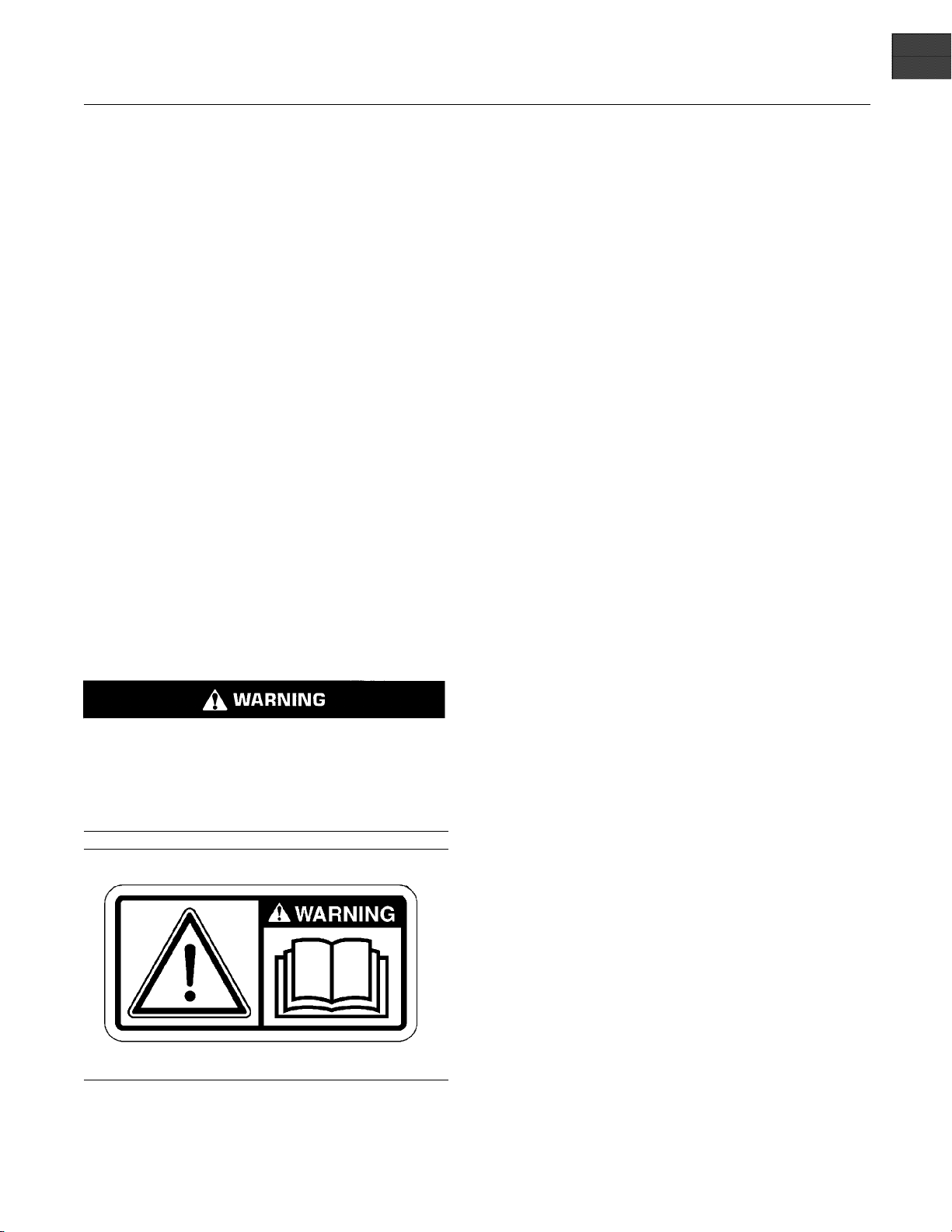
Warning label (
The location will change according to the physical
size of the engine.
A) is installed in different locations.
(A) Universal Warning
Do not operate or work on this equipment unless
you have r
and warnings in the Operation and Maintenance
Manuals. Failure to follow the instructions or
heed the
or death.
Illustration 1
lexample
Typica
ead and understand the instructions
warnings could result in serious injury
g01154807
Page 6
6 SEBU8311-01
This document has been printed from SPI². Not for Resale
Safety Section
Safety Messages
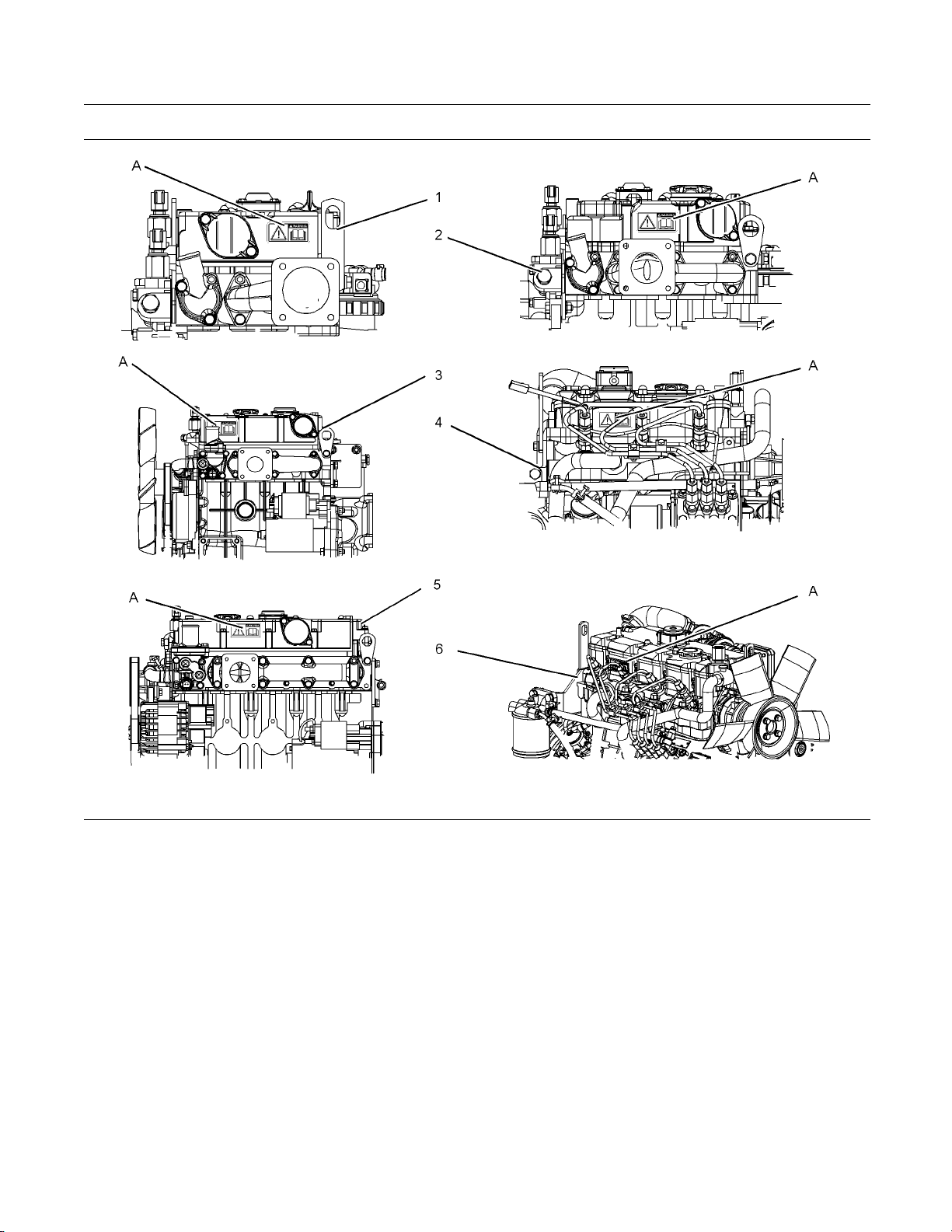
Illustration 2
(A) Location of warning label
(1) 402D-05
(2) 403D-07
(3) 403D-11
(4) 403D-15, 403D-15T and 403D-17
(5) 404D-15
(6) 404D-22, 404D-22T and 404D-22TA
g01324126
Page 7
SEBU8311-01 7
This document has been printed from SPI². Not for Resale
Safety Section
General Hazard Information
i02328435
General Hazard Information
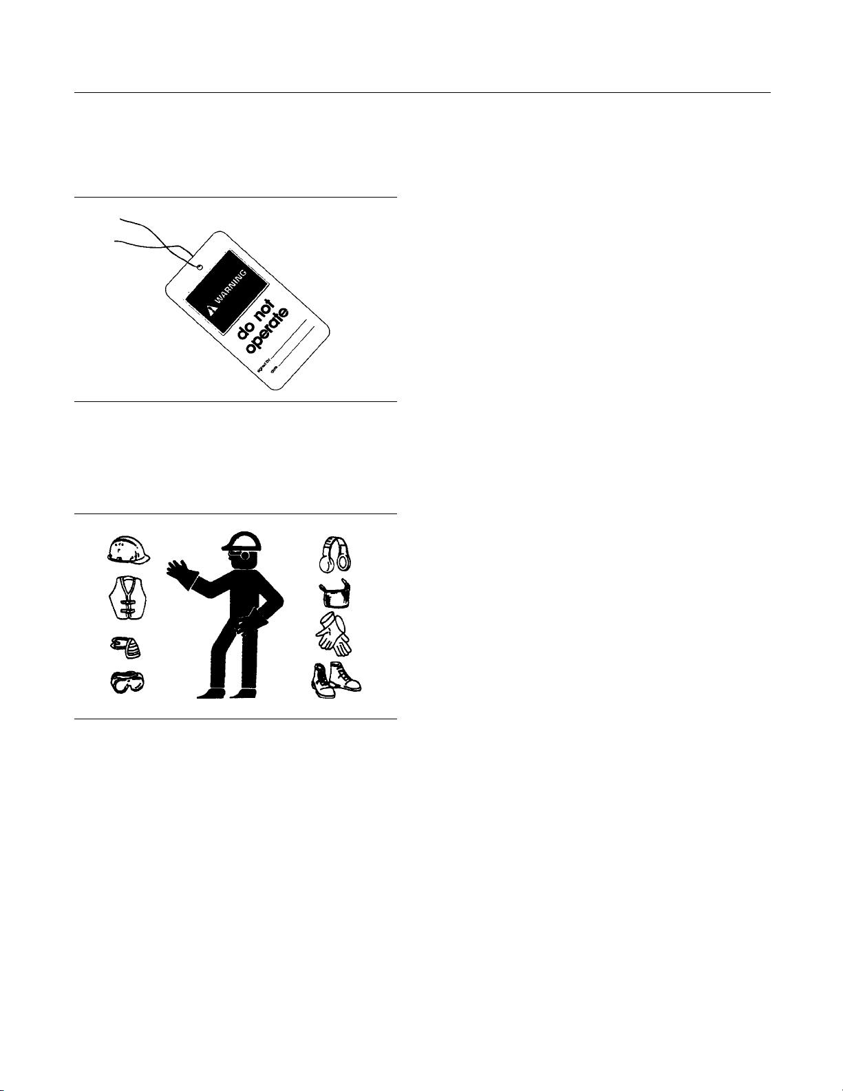
Illustration 3
Attach a “Do Not Operate” warning tag or a similar
warning tag to the start switch or to the controls
before you s
repair the equipment.
ervice the equipment or before you
g00104545
Report all nece
Do not allow unauthorized personnel on the
equipment.
Ensure that the power supply is disconnected before
youworkonthe
Perform maintenance on the engine with the
equipment in t
OEM information for the procedure for placing the
equipment in the servicing position.
ssary repairs.
bus bar or the glow plugs.
he servicing position. Refer to the
Pressure Air and Water
Pressurized air and/or water can cause debris
and/or hot water to be blown out. This could result in
personal inj
The direct application of pressurized air or
pressurize
injury.
When pressu
cleaning, wear protective clothing, protective shoes,
and eye protection. Eye protection includes goggles
or a protect
ury.
d water to the body could result in personal
rized air and/or water is used for
ivefaceshield.
Illustration 4
Wear a hard hat, protective glasses, and other
protective equipment, as required.
Do not wear loose clothing or jewelry that can snag
on controls or on other parts of the engine.
Make sure that all protective guards and all covers
are secured in place on the engine.
Keep the engine free from foreign material. Remove
debris, oil, tools, and other items from the deck, from
walkway
s, and from steps.
g0070202
The maximum air pressure for cleaning purposes
must be belo
water pressure for cleaning purposes must be below
275 kPa (40 psi).
w 205 kPa (30 psi). The maximum
Fluid Penetration
Pressure can be trapped in the hydraulic circuit long
after the engine has been stopped. The pressure can
cause hyd
escape rapidly if the pressure is not relieved correctly.
0
Do not rem
until pressure has been relieved or personal injury
may occur. Do not disassemble any hydraulic
componen
or personal injury may occur. Refer to the OEM
information for any procedures that are required to
relieve
raulic fluid or items such as pipe plugs to
ove any hydraulic components or parts
ts or parts until pressure has been relieved
the hydraulic pressure.
Never put maintenance fluids into glass containers.
Drain al
Obey all local regulations for the disposal of liquids.
Use all cleaning solutions with care.
l liquids into a suitable container.
Page 8
8 SEBU8311-01
This document has been printed from SPI². Not for Resale
Safety Section
Burn Prevention
Coolant
When the engine is at operating temperature, the
engine coolant is hot. The coolant is also under
pressure. The radiator and all lines to the heaters or
to the engine contain hot coolant.
Any contact with hot coolant or with steam can cause
severe burns. Allow cooling system components to
cool before the cooling system is drained.
Check the coolant level after the engine has stopped
and the engine has been allowed to cool.
Illustration 5
Always use a board or cardboard when you check
for a leak. Leaking fluid that is under pressure can
penetrate body tissue. Fluid penetration can cause
serious injury and possible death. A pin hole leak can
cause severe injury. If fluid is injected into your skin,
you must get treatment immediately. Seek treatment
from a doctor that is familiar with this type of injury.
g00687600
Containing Fluid Spillage
Care must be taken in order to ensure that fluids
are contained during performance of inspection,
maintenance, testing, adjusting and repair of the
engine. Make provision to collect the fluidwitha
suitable container before any compartment is opened
or before any component is disassembled.
Only use the tools that are suitable for collecting
•
fluids and equipment that is suitable for collecting
fluids.
Only use the tools that are suitable for containing
•
fluids and equipment that is suitable for containing
fluids.
Obey all local regulations for the disposal of liquids.
Ensure that the filler cap is cool before removing the
filler cap. The filler cap must be cool enough to touch
with a bare hand. Remove the filler cap slowly in
order to relieve pressure.
Cooling system conditioner contains alkali. Alkali can
cause personal injury. Do not allow alkali to contact
the skin, the eyes, or the mouth.
Oils
Hot oil and hot lubricating components can cause
personal injury. Do not allow hot oil to contact the
skin. Also, do not allow hot components to contact
the skin.
Batteries
Electrolyte is an acid. Electrolyte can cause personal
injury. Do not allow electrolyte to contact the skin or
the eyes. Always wear protective glasses for servicing
batteries. Wash hands after touching the batteries
and connectors. Use of gloves is recommended.
i028134
Fire Prevention an d Explosion
Prevent
ion
88
i02143195
Burn Pre
Do not touch any part of an operating engine.
Allow the engine to cool before any maintenance
is perfo
in the air system, in the hydraulic system, in the
lubrication system, in the fuel system, or in the
coolin
items are disconnected.
rmed on the engine. Relieve all pressure
g system before any lines, fittings or related
vention
Illust
ration 6
g00704000
Page 9
SEBU8311-01 9
This document has been printed from SPI². Not for Resale
Safety Section
Fire Prevention and Explosion Prevention
All fuels, most
are flammable.
Flammable flui
surfaces or onto electrical components can cause
a fire. Fire may cause personal injury and property
damage.
A flash fire may result if the covers for the engine
crankcase ar
an emergency shutdown.
Determine wh
environment that allows combustible gases to be
drawn into the air inlet system. These gases could
cause the eng
property damage, or engine damage could result.
If the appli
gases, consult your Perkins dealer and/or your
Perkins distributor for additional information about
suitable p
Remove all flammable combustible materials or
conductiv
the engine. Do not allow any flammable combustible
materials or conductive materials to accumulate on
the engine
lubricants, and some coolant mixtures
ds that are leaking or spilled onto hot
e removed within fifteen minutes after
ether the engine will be operated in an
ine to overspeed. Personal injury,
cation involves the presence of combustible
rotection devices.
e materials such as fuel, oil, and debris from
.
Arcing or spark
connections, recommended wiring, and correctly
maintained battery cables will help to prevent arcing
or sparking.
Inspect all lines and hoses for wear or for
deteriorati
The lines and hoses must have adequate support
and secure clamps. Tighten all connections to the
recommended
Oil filters and fuel
The filter hou
torque.
ing could cause a fire. Secure
on. The hoses must be correctly routed.
torque. Leaks can cause fires.
filters must be correctly installed.
sings must be tightened to the correct
Store fuels and lubricants in correctly marked
container
oily rags and any flammable materials in protective
containers. Do not smoke in areas that are used for
storing fl
Do not expose the engine to any flame.
Exhaust shields (if equipped) protect hot exhaust
components from oil or fuel spray in case of a line,
a tube, or
installed correctly.
Do not we
fluids. Do not flame cut lines or tanks that contain
flammable fluid. Clean any such lines or tanks
thoroug
welding or flame cutting.
Wiring m
wires must be correctly routed and securely attached.
Check all electrical wires daily. Repair any wires
that ar
engine. Clean all electrical connections and tighten
all electrical connections.
Eliminate all wiring that is unattached or unnecessary.
Do not use any wires or cables that are smaller than
the rec
and/or circuit breakers.
s away from unauthorized persons. Store
ammable materials.
a seal failure. Exhaust shields must be
ld on lines or tanks that contain flammable
hly with a nonflammable solvent prior to
ust be kept in good condition. All electrical
e loose or frayed before you operate the
ommended gauge. Do not bypass any fuses
Illustration 7
Use caution when you are refueling an engine. Do
not smoke while you are refueling an engine. Do not
refuel an engine near open flames or sparks. Always
stop the engine before refueling.
g00704059
Page 10
10 SEBU8311-01
This document has been printed from SPI². Not for Resale
Safety Section
Crushing Prevention and Cutting Prevention
Illustration 8
Gases from a battery can explode. Keep any open
flames or sparks away from the top of a battery. Do
not smoke in battery charging areas.
Never check the battery charge by placing a metal
object across the terminal posts. Use a voltmeter or
ahydrometer.
g00704135
Repair any line
can cause fires. Consult your Perkins dealer or your
Perkins distributor for repair or for replacement parts.
Check lines, tubes and hoses carefully. Do not use
your bare hand to check for leaks. Use a board or
cardboard to
to the recommended torque.
Replace the p
are present:
End fittings a
•
Outer coverings are chafed or cut.
•
Wires are exposed.
•
Outer coveri
•
Flexible part of the hoses are kinked.
•
Outer covers have embedded armoring.
•
End fittings a
•
Make sure that all clamps, guards, and heat shields
are installe
will help to prevent vibration, rubbing against other
parts, and excessive heat.
s that are loose or damaged. Leaks
check for leaks. Tighten all connections
arts if any of the following conditions
re damaged or leaking.
ngs are ballooning.
re displaced.
d correctly. During engine operation, this
Incorrect jumper cable connections can cause
an explosion that can result in injury. Refer to
the Operation Section of this manual for specific
instructions.
Do not charge a frozen battery. This may cause an
explosion.
The batteries must be kept clean. The covers
(if equipped) must be kept on the cells. Use the
recommended cables, connections, and battery box
covers when the engine is operated.
Fire Extinguisher
Make sure that a fire extinguisher is available. Be
familiar with the operation of the fire extinguisher.
Inspect the fire extinguisher and service the fire
extinguisher regularly. Obey the recommendations
on the instruction plate.
Lines, Tubes and Hoses
Do not bend high pressure lines. Do not strike high
pressure lines. Do not install any lines that are bent
or damaged. Do not clip any other items to the high
pressure lines.
i02143194
Crushing Prevention and
Cutting Prevention
Support th
the component is performed.
Unless oth
never attempt adjustments while the engine is
running.
Stay clear of all rotating parts and of all moving
parts. Leave the guards in place until maintenance
is perfor
reinstall the guards.
Keep obje
blades will throw objects or cut objects.
When obje
order to avoid injury to the eyes.
Chips or o
are struck. Before objects are struck, ensure that no
one will be injured by flying debris.
e component correctly when work beneath
er maintenance instructions are provided,
med. After the maintenance is performed,
cts away from moving fan blades. The fan
cts are struck, wear protective glasses in
ther debris may fly off objects when objects
Page 11

SEBU8311-01 11
This document has been printed from SPI². Not for Resale
Safety Section
Before Starting Engine
i02813489
Before Starting Engine
Before the init
serviced or repaired, make provision to shut the
engine off, in order to stop an overspeed. This may
be accomplish
supply to the engine.
Overspeed shu
engines that are controlled electronically. If automatic
shutdown does not occur, press the emergency stop
buttoninord
Inspect the engine for potential hazards.
Before starting the engine, ensure that no one is on,
underneath, or close to the engine. Ensure that the
area is free
If equipped, ensure that the lighting system for the
engine is su
lights work correctly, if equipped.
All protect
be installed if the engine must be started in order
to perform service procedures. To help prevent an
accident t
around the parts carefully.
Do not bypa
disable the automatic shutoff circuits. The circuits are
provided in order to help prevent personal injury. The
circuits
engine damage.
See the Se
adjustments.
ial start-up of an engine that is new,
ed by shutting off the air and/or fuel
tdown should occur automatically for
er to cut the fuel and/or air to the engine.
of personnel.
itable for the conditions. Ensure that all
ive guards and all protective covers must
hat is caused by parts in rotation, work
ss the automatic shutoff circuits. Do not
are also provided in order to help prevent
rvice Manual for repairs and for
All protective
be installed if the engine must be started in order
to perform service procedures. T o help prevent an
accident that
around the parts carefully.
Start the eng
from the engine start switch.
Always start
that is described in the Operation and Maintenance
Manual, “Engine Starting” topic in the Operation
Section. Kno
prevent major damage to the engine components.
Knowing the procedure will also help to prevent
personal in
To ensure that the jacket water heater (if equipped)
and/or the l
correctly, check the water temperature gauge and the
oil temperature gauge during the heater operation.
Engine exhaust contains products of combustion
which can be harmful to your health. Always start the
engine and
area. If the engine is started in an enclosed area,
vent the engine exhaust to the outside.
Note: The engine is equipped with an automatic
device for cold starting for normal conditions of
operatio
conditions, then an extra cold starting aid may be
required. Normally, the engine will be equipped with
the corre
operation.
The 400 S
plug starting aid in each individual cylinder that heats
the intake air in order to improve starting.
guards and all protective covers must
is caused by parts in rotation, work
ine from the operator’s compartment or
theengineaccordingtotheprocedure
wing the correct procedure will help to
jury.
ube oil heater (if equipped) is working
operate the engine in a well ventilated
n. If the engine will be operated in very cold
ct type of starting aid for your region of
eries engines are equipped with a glow
i02590389
i02157354
Engine Starting
Do not use aerosol types of starting aids such as
ether. Such use could result in an explosion and
personal injury.
If a warning tag is attached to the engine start switch
or to the controls, DO NOT start the engine or move
the controls. Consult with the person that attached
the warning tag before the engine is started.
Engine St opp ing
To avoid overheating of the engine and accelerated
wear of the engine components, stop the engine
according to this Operation and Maintenance Manual,
“Engine Stopping” topic (Operation Section).
Use the Emergency Stop Button (if equipped)
ONLY in an emergency situation. DO N OT use the
Emergency Stop Button for normal engine stopping.
After an emergency stop, DO NOT start the engine
until the problem that caused the emergency stop
has been corrected.
Page 12

12 SEBU8311-01
This document has been printed from SPI². Not for Resale
Safety Section
Electrical System
On the initial s
that has been serviced, make provisions to stop the
engine if an overspeed condition occurs. This may be
accomplished
the air supply to the engine.
If equipped,
controlled engine, cut the power to the engine.
tart-up of a new engine or an engine
by shutting off the fuel supply and/or
in order to stop an electronically
i02176668
Electrical System
Never disconnect any charging unit circuit or battery
circuit cable from the battery when the charging unit
is operating. A spark can cause the combustible
gases that are produced by some batteries to ignite.
To help prevent sparks from igniting combustible
gases that are produced by some batteries, the
negative “−” jump start cable should be connected
last from the external power source to the negative
“−” terminal of the starting motor. If the starting motor
is not equipped with a negative “−” terminal, connect
thejumpstartcabletotheengineblock.
Check the electrical wires daily for wires that are
loose or frayed. Tighten all loose electrical wires
before the engine is started. Repair all frayed
electrical wires before the engine is started. See
the Operation and Maintenance Manual for specific
starting instructions.
Grounding Practices
Correct grounding for the engine electrical system
is necessary for optimum engine performance
and reliability. Incorrect grounding will result in
uncontrolled electrical circuit paths and in unreliable
electrical circuit paths.
Uncontrolled electrical circuit paths can result in
damage to main bearings, to crankshaft bearing
journal surfaces, and to aluminum components.
Engines that are installed without engine-to-frame
ground straps can be damaged by electrical
discharge.
To ensure that the engine and the engine electrical
systems function correctly, an engine-to-frame
ground strap with a direct path to the battery must be
used. This path may be provided by way of a direct
engine ground to the frame.
All grounds should be tight and free of corrosion. The
engine alternator must be grounded to the negative
“-” battery terminal with a wire that is adequate to
handle the full charging current of the alternator.
Page 13
SEBU8311-01 13
This document has been printed from SPI². Not for Resale
Product Information Section
Model Views
Product Information
Section
Model Views
i02590436
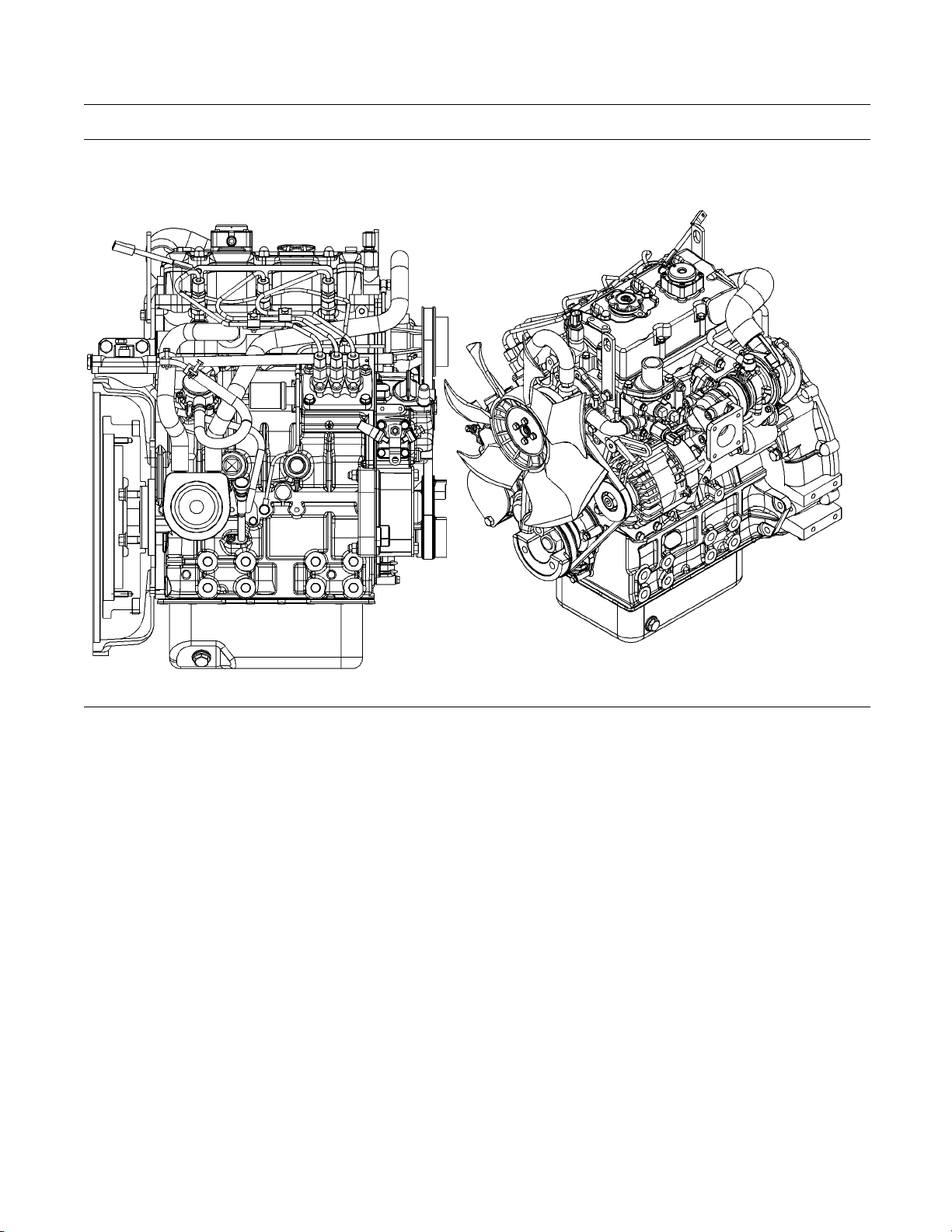
Model View Illustrations
The following model views show typical features
of the 400 series engines. Due to individual
applications, your engine may appear different from
the illustrations.
Note: Individual components are detailed on the
404D-22T turbocharged engine only.
Illustration 9
Typical view of the 402D-05 engine
g01299985
Page 14
14 SEBU8311-01
This document has been printed from SPI². Not for Resale
Product Information Section
Model Views
Illustration 10
Typical view of the 403D-15 T engine
g01300431
Page 15
SEBU8311-01 15
This document has been printed from SPI². Not for Resale
Product Information Section
Model Views
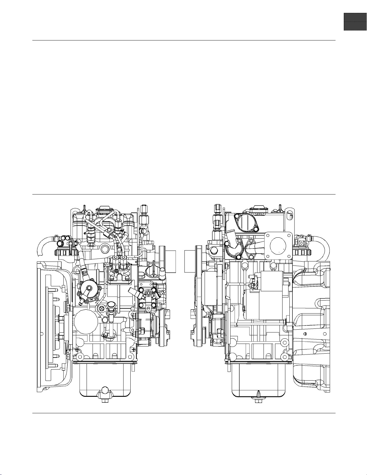
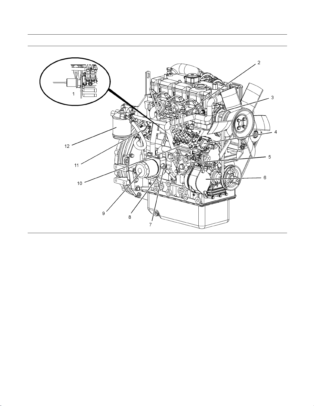
Illustration 11
Front and right side view of the 404D-22T Engine
(1) Fuel shutoff solenoid
(2) Number one fuel injector
(3) Water pump
(4) Lower engine oil filler cap
(5) Throttle lever
(6) Cover plate for the a ccessory drive
(7) Engine oil level gauge
(8) Engine oil coo ler
g01304893
(9) Engine oil filter
(10) Fuel injection pump
(11) Transfer pump
(12) Fuel filter
Page 16
16 SEBU8311-01
This document has been printed from SPI². Not for Resale
Product Information Section
Model Views
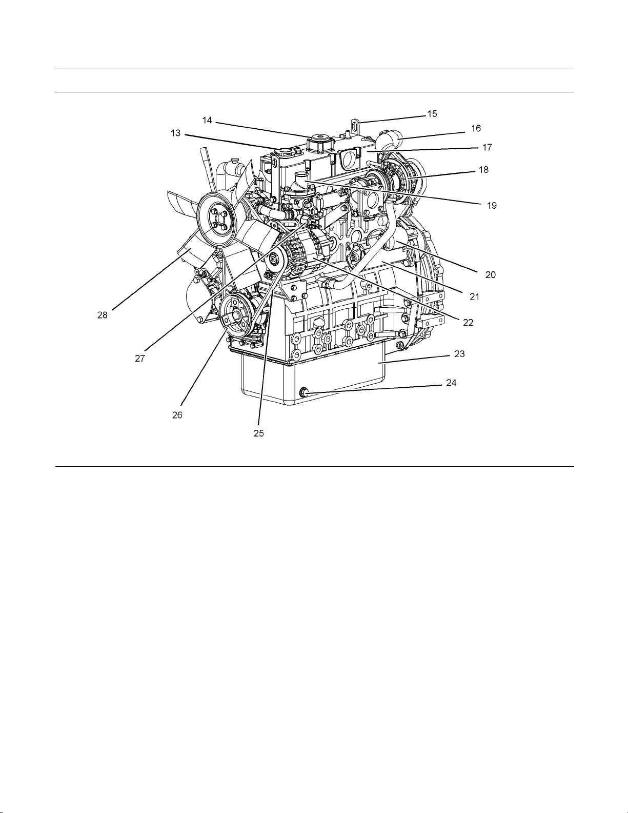
Illustration 12
Front and left side view of the 404D-22T Engine
(13) Top engine oil filler c ap
(14) Crankcase breather
(15) Rear Lifting eye
(16) Air inlet elbow
(17) Valve mechanism cover
(18) Turbocharger
(19) Water temperature regulator hous ing
(20) Starting motor solenoid
(21) Electric starting motor
(22) Alternator
(23) Engine oil pan
(24) Engine oil drain plug
i02959055
Engine De script ion
The 400 series engines are indirect injection engines.
The engines are controlled with a mechanically
actuated fuel injection pump. The engine cylinders
are arranged in-line.
The cylinder head assembly has one inlet valve and
one exhaust valve for each cylinder. Each cylinder
valve has a single valve spring.
g01305224
(25) Fan drive belt
(26) Crankshaft pulley
(27) Coolant tem perature switch
(28) Cooling fan
The pistons have two compression rings and an
oil control ring. It is important to ensure the correct
piston height so that the piston does not contact the
cylinder head. The correct piston height also ensures
efficient combustion of fuel that is necessary in order
to conform to requirements for emissions.
The crankshaft for a two cylinder engine has two
main bearing journals. The crankshaft for a three
cylinder engine has four main bearing journals. The
crankshaft for a four cylinder engine has five main
bearing journals. End play is controlled by the thrust
washers that are located on the rear main bearing.
Page 17

SEBU8311-01 17
This document has been printed from SPI². Not for Resale
Product Information Section
Model Views
The timing gear
order to ensure the correct assembly of the gears.
WhentheNo.1pistonisattopcentercompression
stroke, the te
gear and the camshaft gear will be in alignment with
the idler gear.
The crankshaft gear turns the idler gear which then
turns the camshaft gear and the gear for the engine
oil pump.
The fuel injection pump is mounted in the cylinder
block. The fu
on the camshaft. The fuel transfer pump is located
on the right hand side of the cylinder block. The
fuel transf
camshaft.
The fuel inj
for emissions. If any adjustments to the fuel injection
pumptimingandhighidlearerequiredyoumust
refer to yo
dealer. Some fuel injection pumps have mechanical
governors that control the engine rpm. Some fuel
injection
controlled.
s are stamped with timing marks in
eth that are stamped on the crankshaft
el injection pump is operated by lobes
er pump is also operated by lobes on the
ection pump conforms to requirements
ur Perkins distributoror your Perkins
pumps have a governor that is electrically
Engine Specifications
Note: The front end of the engine is opposite the
flywheel end of the engine. The left and the right side
of the engine are determined from the flywheel end.
The No. 1 cylinder is the front cylinder.
A gerotor
gear. The engine oil pump sends lubricating oil to the
main oil gallery through a pressure relief valve and an
engine oi
oil through an externally located oil line that runs from
the main oil gallery to the cylinder head.
Coolant from the bottom of the radiator passes
through the belt driven centrifugal water pump. The
coolant
is regulated by a water temperature regulator.
Engine e
engine performance depend on adherence to correct
operation and maintenance recommendations.
Engine
the use of recommended fuels, lubrication oils, and
coolants. Refer to the Operation and Maintenance
Manual
information on maintenance items.
oil pump is located in the center of the idler
l filter. The rocker arms receive pressurized
is cooled by the radiator and the temperature
fficiency, efficiency of emission controls, and
performance and efficiency also depend on
, “Maintenance Interval Schedule” for more
Page 18
18 SEBU8311-01
This document has been printed from SPI². Not for Resale
Product Information Section
Model Views
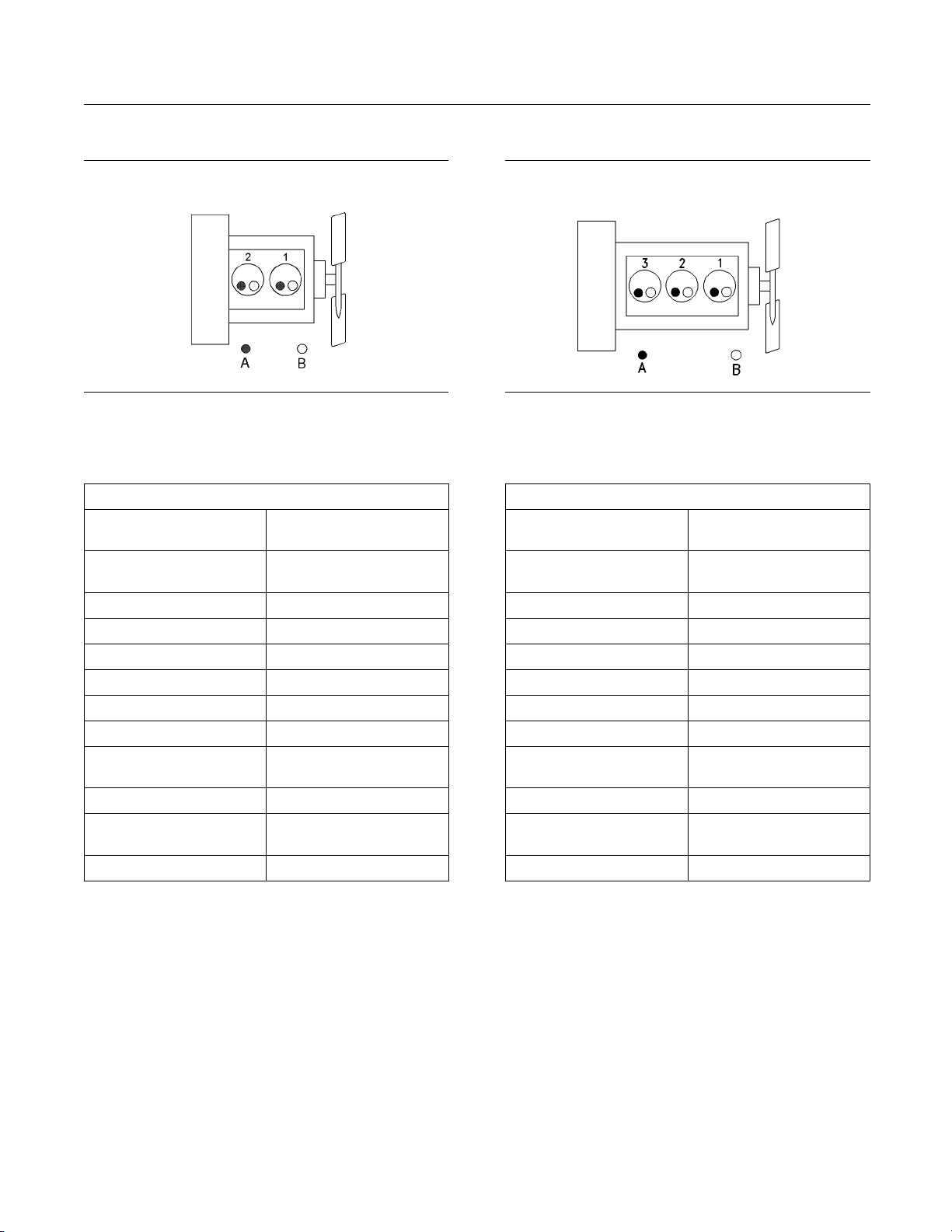
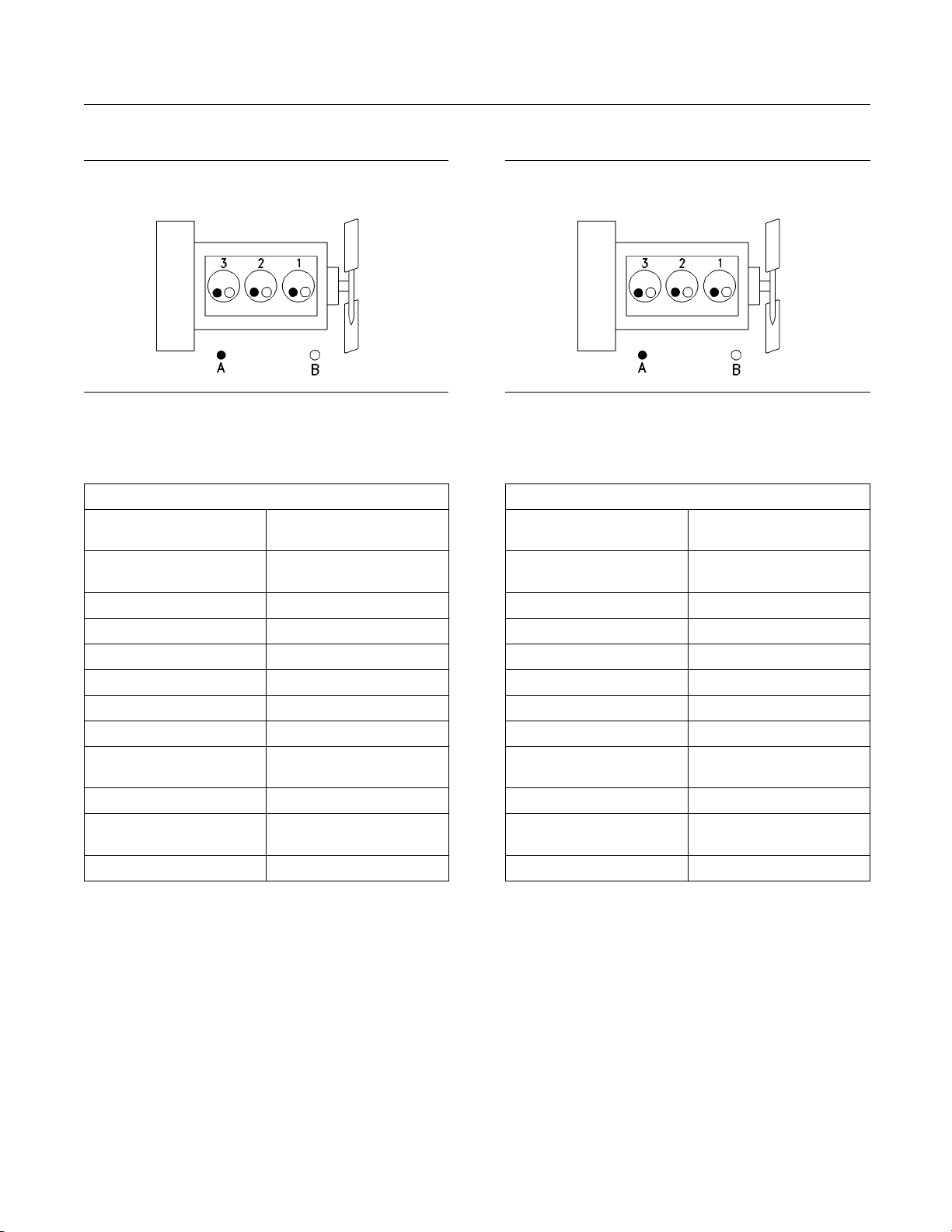
402D-05 Engine
Illustratio
(A) Ex haust valves
(B) I nlet valves
Table 1
n13
402D-05 Engine Specifications
Maximum Operating
Speed (rpm)
Cylinders and
Arrangement
Bore
3600 rpm
In-Line two cylinder
67 mm (2.64 inch)
Stroke 72 mm (2.83 inch)
Displacement 0.507 L (30.939 in3)
Aspiration NA
Compression Ratio
Firing Order
Rotation that is viewed
from the fly
wheel
23.5:1
1-2
Counterclockwise
Valve Lash Setting (Inlet) 0.20 mm (0.008 inch)
Valve Lash Setting
(Exhaust)
0.20 mm (0.008 inch)
Injection Indirect
(1)
Naturally Aspirated
g01108476
(1)
403D-07 Engine
Illustratio
(A) Exhaus t valves
(B) Inlet valves
Table 2
n14
403D-07 Engine Specifications
Maximum Operating
Speed (rpm)
Cylinders and
Arrangement
Bore
3600 rpm
In-Line three cylinder
67 mm (2.64 inch)
Stroke 72 mm (2.83 inch)
Displacement 0.762 L (46.500 in3)
Aspiration NA
Compression Ratio
Firing Order
Rotation that is viewed
from the fly
wheel
23.5:1
1-2-3
Counterclockwise
Valve Lash Setting (Inlet) 0.20 mm (0.008 inch)
Valve Lash Setting
(Exhaust)
0.20 mm (0.008 inch)
Injection Indirect
(1)
Naturally A spirat ed
g00852304
(1)
Page 19

SEBU8311-01 19
This document has been printed from SPI². Not for Resale
Product Information Section
Model Views
403D-11 Engine
Illustratio
(A) Ex haust valves
(B) I nlet valves
Table 3
n15
403D-11 Engine Specifications
Maximum Operating
Speed (rpm)
Cylinders and
Arrangement
Bore
3600 rpm
In-Line three cylinder
77 mm (3.03 inch)
Stroke 81 mm (3.19 inch)
Displacement 1.131 L (69.018 in3)
Aspiration NA
Compression Ratio
Firing Order
Rotation that is viewed
from the fly
wheel
23:1
1-2-3
Counterclockwise
Valve Lash Setting (Inlet) 0.20 mm (0.008 inch)
Valve Lash Setting
(Exhaust)
0.20 mm (0.008 inch)
Injection Indirect
(1)
Naturally Aspirated
g00852304
(1)
403D-15 Engine
Illustratio
(A) Exhaus t valves
(B) Inlet valves
Table 4
n16
403D-15 Engine Specifications
Maximum Operating
Speed (rpm)
Cylinders and
Arrangement
Bore
3000 rpm
In-Line three cylinder
84 mm (3.31 inch)
Stroke 90 mm (3.54 inch)
Displacement 1.496 L (91.291 in3)
Aspiration NA
Compression Ratio
Firing Order
Rotation that is viewed
from the fly
wheel
22.5:1
1-2-3
Counterclockwise
Valve Lash Setting (Inlet) 0.20 mm (0.008 inch)
Valve Lash Setting
(Exhaust)
0.20 mm (0.008 inch)
Injection Indirect
(1)
Naturally A spirat ed
g00852304
(1)
Page 20
20 SEBU8311-01
This document has been printed from SPI². Not for Resale
Product Information Section
Model Views
403D-15T Engin
Illustratio
(A) Ex haust valves
(B) I nlet valves
Table 5
n17
e
g00852304
403D-15T Engine Specifications
Maximum Operating
Speed (rpm)
Cylinders and
Arrangement
Bore
3000 rpm
In-Line three cylinder
84 mm (3.31 inch)
Stroke 90 mm (3.54 inch)
Displacement 1.496 L (91.291 in3)
Aspiration T
Compression Ratio
Firing Order
Rotation that is viewed
from the fly
wheel
Counterclockwise
(1)
22.5:1
1-2-3
Valve Lash Setting (Inlet) 0.20 mm (0.008 inch)
Valve Lash Setting
(Exhaust)
0.20 mm (0.008 inch)
Injection Indirect
(1)
Turbocharged
403D-17 Engine
Illustratio
(A) Exhaus t valves
(B) Inlet valves
Table 6
n18
403D-17 Engine Specifications
Maximum Operating
Speed (rpm)
Cylinders and
Arrangement
Bore
2600 rpm
In-Line three cylinder
84 mm (3.31 inch)
Stroke 100 mm (3.94 inch)
Displacement 1.66 L (101.3 in3)
Aspiration NA
Compression Ratio
Firing Order
Rotation that is viewed
from the fly
wheel
23.1:1
1-2-3
Counterclockwise
Valve Lash Setting (Inlet) 0.20 mm (0.008 inch)
Valve Lash Setting
(Exhaust)
0.20 mm (0.008 inch)
Injection Indirect
(1)
Naturally A spirat ed
g00852304
(1)
Page 21

SEBU8311-01 21
This document has been printed from SPI². Not for Resale
Product Information Section
Model Views
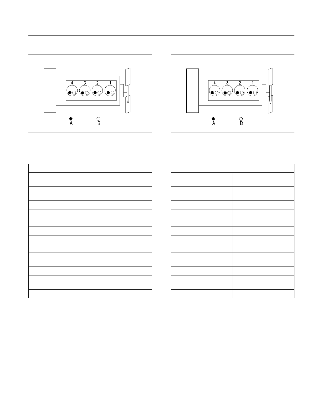
404D-15 Engine
Illustratio
(A) Ex haust valves
(B) I nlet valves
Table 7
n19
404D-15 Engine Specifications
Maximum Operating
Speed (rpm)
Cylinders and
Arrangement
Bore
3000 rpm
In-Line four cylinder
77 mm (3.03 inch)
Stroke 81 mm (3.19 inch)
Displacement 1.508 L (92.024 in3)
Aspiration NA
Compression Ratio
Firing Order
Rotation that is viewed
from the fly
wheel
23.5:1
1-3-4-2
Counterclockwise
Valve Lash Setting (Inlet) 0.20 mm (0.008 inch)
Valve Lash Setting
(Exhaust)
0.20 mm (0.008 inch)
Injection Indirect
(1)
Naturally Aspirated
g00296424
(1)
404D-22 Engine
Illustratio
(A) Exhaus t valves
(B) Inlet valves
Table 8
n20
404D-22 Engine Specifications
Maximum Operating
Speed (rpm)
Cylinders and
Arrangement
Bore
3000 rpm
In-Line four cylinder
84.0 mm (3.31 inch)
Stroke 100.0 m m (3.94 inch)
Displacement 2.216 L (135.229 in3)
Aspiration NA
Compression Ratio
Firing Order
Rotation that is viewed
from the fly
wheel
23.3:1
1-3-4-2
Counterclockwise
Valve Lash Setting (Inlet) 0.20 mm (0.008 inch)
Valve Lash Setting
(Exhaust)
0.20 mm (0.008 inch)
Injection Indirect
(1)
Naturally A spirat ed
g00296424
(1)
Page 22
22 SEBU8311-01
This document has been printed from SPI². Not for Resale
Product Information Section
Model Views
404D-22T Engin
Illustratio
(A) Ex haust valves
(B) I nlet valves
Table 9
n21
e
g00296424
404D-22T Engine Specifications
Maximum Operating
Speed (rpm)
Cylinders and
Arrangement
Bore
3000 rpm
In-Line four cylinder
84.0 mm (3.31 inch)
Stroke 100.0 mm (3.94 inch)
Displacement 2.216 L (135.229 in3)
Aspiration T
Compression Ratio
Firing Order
Rotation that is viewed
from the fly
wheel
Counterclockwise
(1)
23.5:1
1-3-4-2
Valve Lash Setting (Inlet) 0.20 mm (0.008 inch)
Valve Lash Setting
(Exhaust)
0.20 mm (0.008 inch)
Injection Indirect
(1)
Turbocharged
404D-22TA Engi
Illustratio
(A) Exhaus t valves
(B) Inlet valves
Table 10
n22
ne
g00296424
404D-22TA Engine Specifications
Maximum Operating
Speed (rpm)
Cylinders and
Arrangement
Bore
2800 rpm
In-Line four cylinder
84.0 mm (3.31 inch)
Stroke 100.0 m m (3.94 inch)
Displacement 2.216 L (135.229 in3)
Aspiration TA
Compression Ratio
Firing Order
Rotation that is viewed
from the fly
wheel
Counterclockwise
(1)
23.5:1
1-3-4-2
Valve Lash Setting (Inlet) 0.20 mm (0.008 inch)
Valve Lash Setting
(Exhaust)
0.20 mm (0.008 inch)
Injection Indirect
(1)
Turbocharged aftercooled
Page 23
SEBU8311-01 23
This document has been printed from SPI². Not for Resale
Product Information Section
Product Identification Information
Product Identification
Information
i02643641
Engine Identification
Perkins engines are identified by a serial number.
This number is shown on a serial number plate that
is mounted above the fuel injection pump on the right
hand side of the engine block.
An example of an engine number is
GP*****U000001M.
GP
________________________________ _________Type of engine
____________________________ Built in the United Kingdom
U
______________________ The list number of the engine
*****
000001
___________________________ Engine Serial Number
The following i
Number Plate: Engine serial number, Model, and
Arrangement number.
nformation is stamped on the Serial
i02164876
Reference Numbers
Information for the following items may be needed to
order parts. Locate the information for your engine.
Record the information in the appropriate space.
Make a copy of this list for a record. Keep the
information for future reference.
Record for Reference
Engine Model _ ______________________________________________
Engine Serial number _____________________________________
Engine Low Idle rpm ______________________________________
Engine Full Load rpm _____________________________________
____________________________________ Year of Manufacture
M
Perkins dealers or Perkins distributors need all of
these numbers in order to determine the components
that were included with the engine. This permits
accurate identification of replacement part numbers.
i02157258
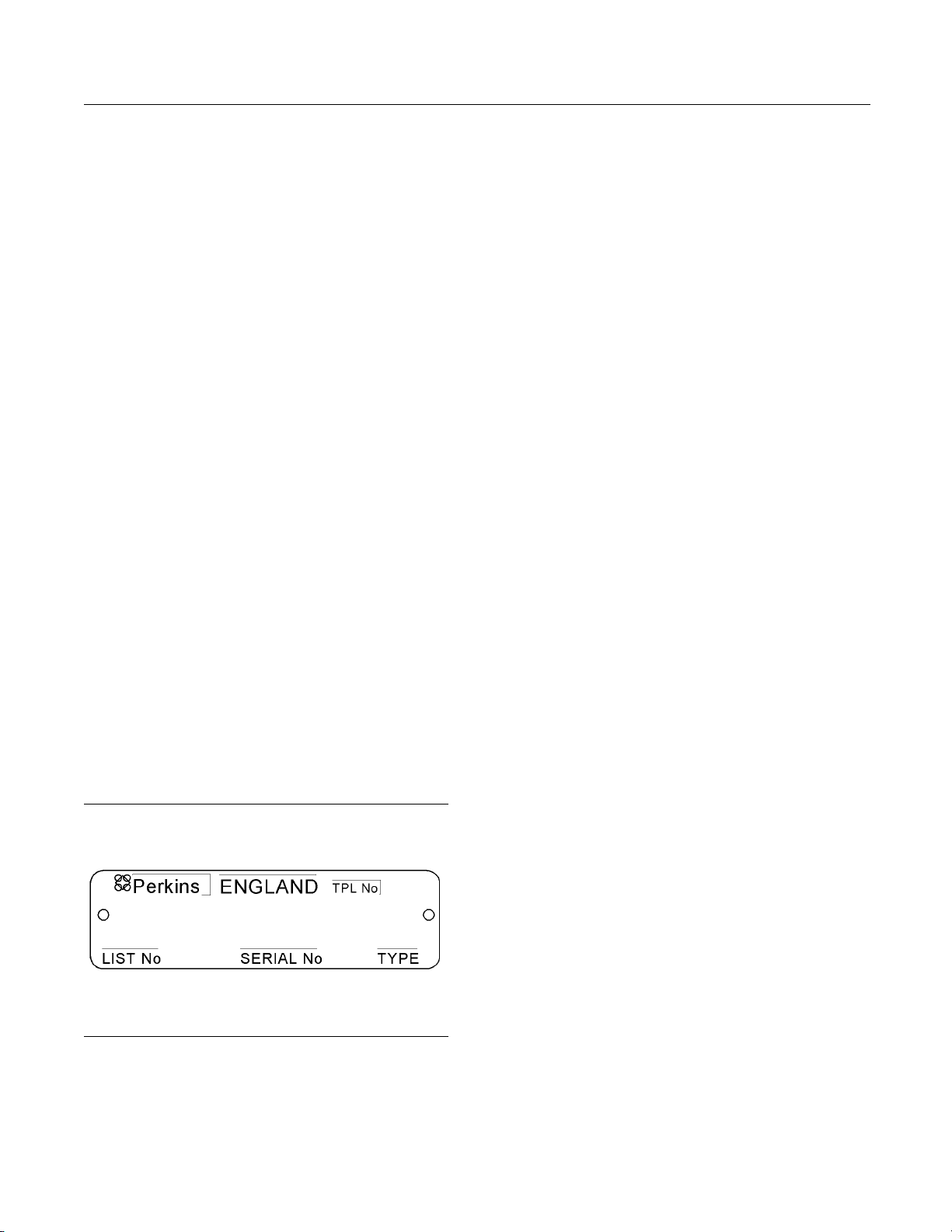
Serial Number Plate
Primary Fuel Filter _________________________________________
Water Separator Element ________________________________
Secondary Fuel Filter Element __________________________
Lubrication Oil Filter Element ___________________________
Auxiliary Oil Filter Element _______________________________
Total Lubrication System Capacity ______ _______________
Total Cooling System Capacity _________________________
Air Cleaner Element _______________________________________
Fan Drive Belt ______________________________________________
Alternator Belt ______________________________________________
tion 23
Illustra
Typical serial number plate
The Serial Number Plate is located above the fuel
injection pump on the right side of the cylinder block.
g01094203
Page 24
24 SEBU8311-01
This document has been printed from SPI². Not for Resale
Product Information Section
Product Identification Information
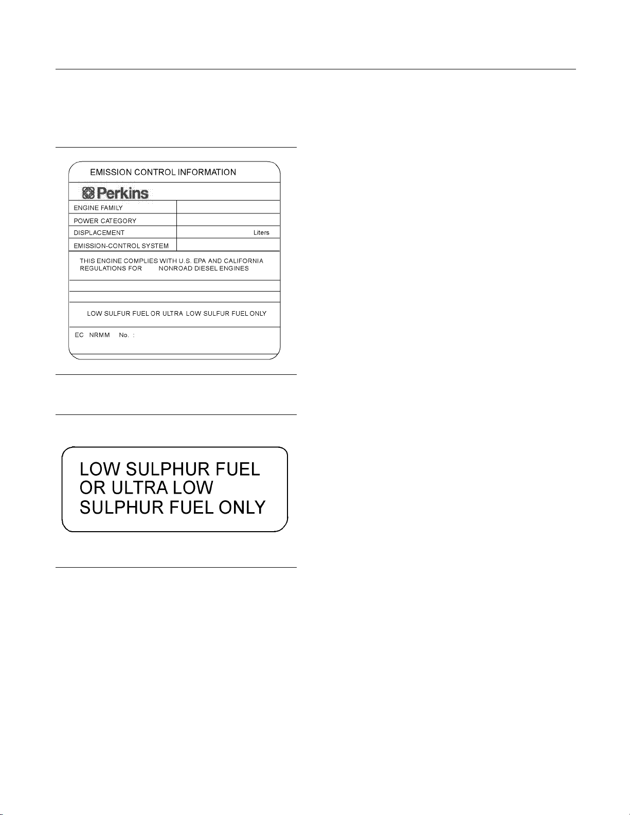
i02959144
Emissions Certification Film
Illustration 24
Typical exam p le
Illustration 25
Typical exam p le
g01478138
g01476654
Perkins Shibaura Engines Limited will supply the
fuel label with every engine. Refer to illustration
25. The equipment manufacturer must install the
label to the equipment. This is recommended by
Perkins Shibaura Engines Limited. The label must be
attached to the equipment near the fuel inlet. This
will comply with the EPA regulations. The equipment
manufacturer may install another fuel label. If another
fuel label is used, the equipment manufacturer must
send a drawing or a photo of the label to Perkins
Shibaura Engines Limited through the Perkins
Distributor. This will ensure compliance of the label.
Page 25
SEBU8311-01 25
This document has been printed from SPI². Not for Resale
Operation Section
Lifting and Storage
Operation Section
Lifting and Storage
Engine Lifting
i02164186
Some removals r
obtain correct balance and safety.
To r em ov e t h e e
are on the engine.
Lifting eyes a
engine arrangements. Alterations to the lifting eyes
and/or the engine make the lifting eyes and the lifting
fixtures obso
that correct lifting devices are provided. Consult
your Perkins dealer or your Perkins distributor for
information
lifting.
equire lifting the fixtures in order to
ngine ONLY, use the lifting eyes that
re designed and installed for specific
lete. If alterations are made, ensure
regarding fixtures for correct engine
i02593735
Engine Storage
If the engine will not be started for several weeks, the
lubricating oil will drain from the cylinder walls and
from the piston rings. Rust can form on the cylinder
walls. Rust on the cylinder walls will cause increased
engine wear and a reduction in engine service life.
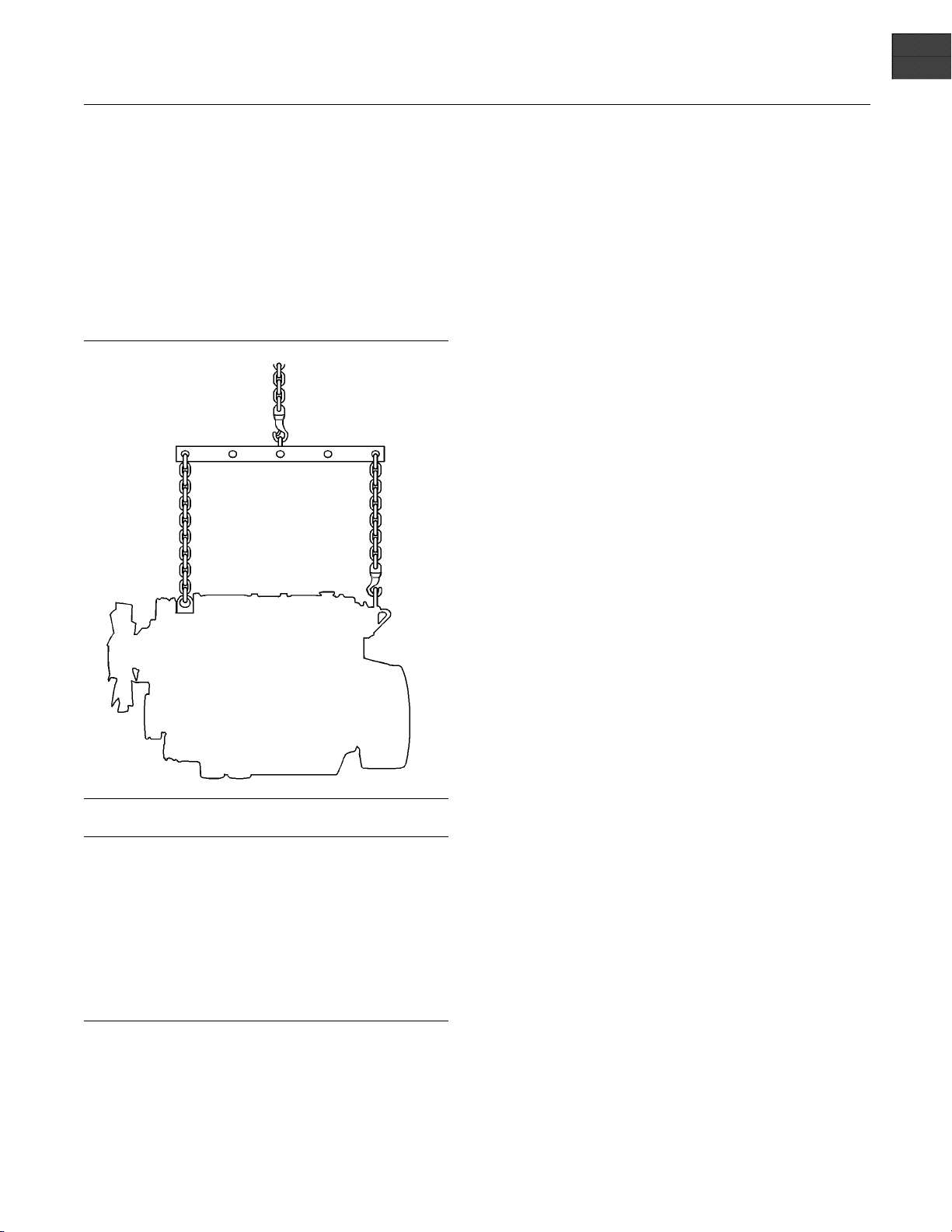
Illustration 26
NOTICE
Never bend the eyebolts and the brackets. Only load
the eyeb
ber that the capacity of an eyebolt is less as the angle
between the supporting members and the object becomes le
When it is necessary to remove a component at an
angle, o
the weight.
Use a ho
an adjustable lifting beam to lift the engine. All
supporting members (chains and cables) should be
parall
be perpendicular to the top of the object that is being
lifted.
olts and the brackets under tension. Remem-
ss than 90 degrees.
nly use a link bracket that is properly rated for
ist to remove heavy components. Use
el to each other. The chains and cables should
g01097527
Lubrication System
To help prevent excessive engine wear, use the
following guidelines:
Complete all of the lubrication recommendations that
are listed in this Operation and Maintenance Manual,
“Maintenance Interval Schedule” (Maintenance
Section).
If an engine is out of operation and if use of the engine
is not planned, special precautions should be made.
If the engine will be stored for more than one month,
a complete protection procedure is recommended.
Use the following guidelines :
Completely clean the outside of the engine.
•
Drain the fuel system completely and refill
•
thesystemwithpreservativefuel.1772204
POWERPART Lay-Up 1 can be mixed with
the normal fuel in order to change the fuel into
preservative fuel.
If preservative fuel is not available, the fuel system
•
can be filled with normal fuel. This fuel must be
discarded at the end of the storage period together
with the fuel filter elements.
Operate the engine until the engine reaches normal
•
operating temperature. Stop any leaks from fuel,
lubricating oil or air systems. Stop the engine and
drain the lubricating oil from the oil pan.
Page 26
26 SEBU8311-01
This document has been printed from SPI². Not for Resale
Operation Section
Lifting and Storage
Renew the canis
•
FilltheoilpantotheFullMarkontheengineoil
•
level gauge wi
1762811 POWERPART Lay-Up 2 to the oil in
order to protect the engine against corrosion. If
1762811 POWE
use a preservative of the correct specification
instead of the lubricating oil. If a preservative is
used, this mu
the storage period and the oil pan must be refilled
to the correct level with normal lubricating oil.
ter(s) of the lubricating oil filter.
th new, clean lubricating oil. Add
RPART Lay-Up 2 is not available,
st be drained completely at the end of
Cooling System
To help prevent excessive engine wear, use the
following guidelines:
NOTICE
Do not drain the coolant while the engine is still hot and
the system is under pressure because dangerous hot
coolant can
If freezing temperatures are expected, check the
cooling sys
freezing. Refer to this Operation and Maintenance
Manual, “Fluid Recommendations” (Maintenance
Section).
To prevent frost damage, ensure that all the coolant is
removed fr
tem is drained after it has been flushed with water, or if
an antifreeze solution too weak to protect the system
from frost
be discharged.
tem for adequate protection against
NOTICE
om the engine. This is important if the sys-
has been used.
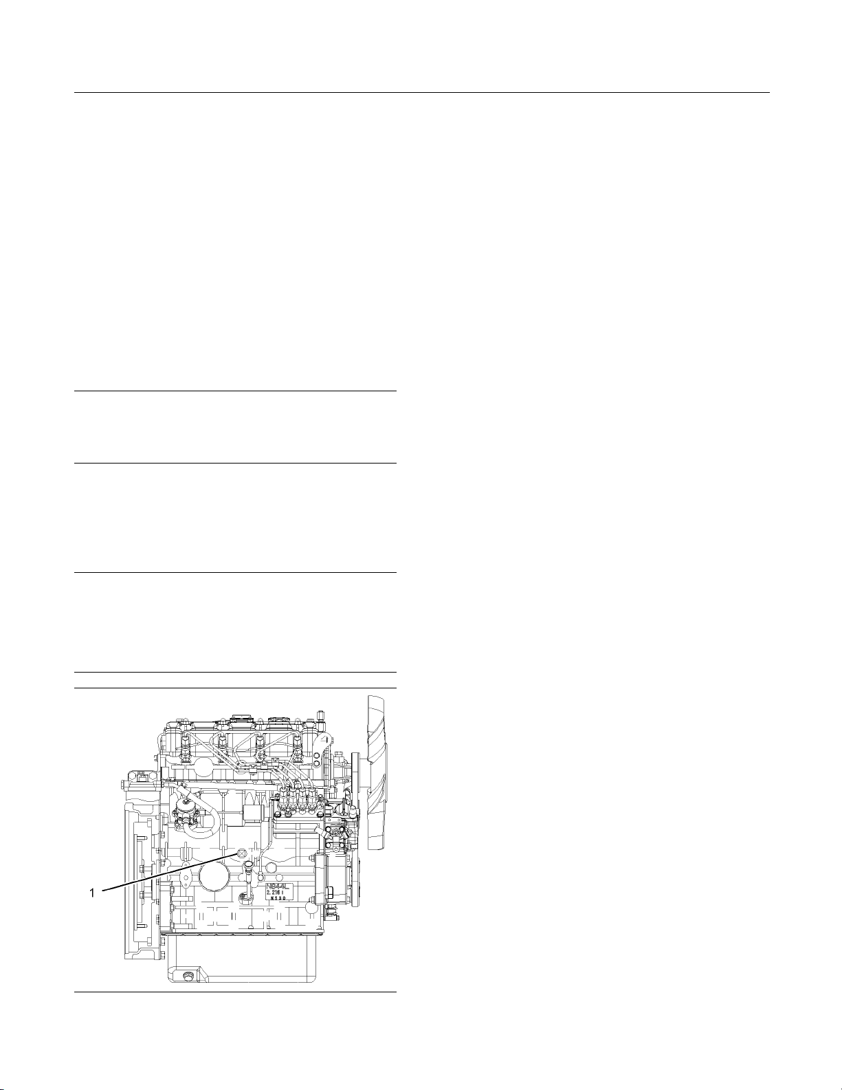
1. Ensure that the
2. Remove the filler cap of the cooling system.
3. Remove the drain plug (1) from the side of the
cylinder block in order to drain the engine. Ensure
that the drain
4. Open the tap or remove the drain plug at the
bottom of the r
If the radiator does not have a tap or a drain plug,
disconnect the hose at the bottom of the radiator.
5. Flushthecoolingsystemwithcleanwater.
6. Fit the drain
or connect the radiator hose.
7. Fill the cool
mixture because this gives protection against
corrosion.
Note: Certain corrosion inhibitors could cause
damage to some engine components. Contact the
Service Dep
8. Operate the engine for a short period in order to
circulate t
engine.
9. Disconnect
storage in a fully charged condition. Before the
battery is put into storage, protect the terminals
against co
Lay-Up 3 can be used on the terminals.
10. Clean the c
Seal the end of the pipe.
vehicle is on level ground.
hole is not restricted.
adiator in order to drain the radiator.
plugs and the filler cap. Close the tap
ing system with an approved antifreeze
artment of Perkins for advice.
he lubricating oil and the coolant in the
the battery. Put the battery into safe
rrosion. 1734115 POWERPART
rankcase breather if one is installed.
11. Remove the
POWERPART Lay-Up 2 for one or two seconds
into each cylinder bore with the piston at BDC.
12. Slowly rotate the crankshaft for one complete
revolution and then replace the fuel injectors.
fuel injectors and spray 1762811
Induction System
Remove the air filter assembly. If necessary,
•
remove the pipes that are installed between
ter assembly and the turbocharger.
ntainer. Seal the turbocharger with
Illustration 27
Typical exam p le
the air fil
Spray 1762811 POWERPART Lay-Up 2 into the
turbocharger. The duration of the spray is printed
on the co
waterproof tape.
g01298045
Page 27

SEBU8311-01 27
This document has been printed from SPI². Not for Resale
Operation Section
Lifting and Storage
Exhaust System
Remove the exhaust pipe. Spray 1762811
•
POWERPART Lay-Up 2 into the turbocharger. The
duration of the spray is printed on the container.
Seal the turbocharger with waterproof tape.
General Items
If the lubricating oil filler is installed on the valve
•
mechanism cover, remove the filler cap. If the
lubricating oil filler cap is not installed on the valve
mechanism cover, remove the valve mechanism
cover. Spray 1762811 POWERPART Lay-Up 2
around the rocker shaft assembly. Replace the
filler cap or the valve mechanism cover.
Seal the vent of the fuel tank or the fuel filler cap
•
with waterproof tape.
Remove the alternator drive belts and put the drive
•
belts into storage.
In order to prevent corrosion, spray the engine with
•
1734115 POWERPART Lay-Up 3. Do not spray
the area inside the alternator.
When the engine protection has been completed in
accordance with these instructions, this ensures that
no corrosion will occur. Perkins are not responsible
for damage which may occur when an engine is in
storage after a period in service.
Your Perkins dealer or your Perkins distributor can
assist in preparing the engine for extended storage
periods.
Page 28
28 SEBU8311-01
This document has been printed from SPI². Not for Resale
Operation Section
Gauges and Indicators
Gauges and Ind icators
i02216960
Gauges and Indicators
Your engine m
the gauges that are described. For more information
about the gauge package, see the OEM information.
Gauges provide indications of engine performance.
Ensure that the gauges are in good working order.
Determine th
the gauges over a period of time.
Noticeable c
potential gauge or engine problems. Problems may
also be indicated by gauge readings that change
even if the r
Determine and correct the cause of any significant
change in the readings. Consult your Perkins dealer
or your Per
If no oil pressure is indicated, STOP the engine. If
maximum co
the engine. Engine damage can result.
SAE10W30
rpm.
ay not have the same gauges or all of
e normal operating range by observing
hanges in gauge readings indicate
eadings are within specifications.
kins distributor for assistance.
NOTICE
olant temperature is exceeded, STOP
Engine Oil
should be greatest after a cold engine is
started. The typical engine oil pressure with
is 207 to 413 kPa (30 to 60 psi) at rated
Pressure – The oil pressure
1. Reduce the load
2. Inspect the cooling system for leaks.
3. Determine if the engine must be shut down
immediately or if the engine can be cooled by
reducing the l
Tachometer – This gauge indicates engine
speed (rpm). W
ismovedtothefullthrottlepositionwithout
load, the engine is running at high idle. The engine is
running at th
lever is at the full throttle position with maximum
rated load.
To help prevent engine damage, never exceed the
high idle rpm. Overspeeding can result in serious
damage to the engine. The engine can be operated
at high idle without damage, but should never be
allowedtoexceedhighidlerpm.
indicator should be to the right side of “0” (zero).
is in the “ON” position.
efullloadrpmwhenthethrottlecontrol
Ammeter – This gauge indicates the
amount of charge or discharge in the
battery charging circuit. Operation of the
Fuel Level – This gauge indicates the fuel
level in the fuel tank. The fuel level gauge
operates when the “START/ST OP” switch
Service Hour Meter – The gauge indicates
operating time of the engine.
and the engine rpm.
oad.
hen the throttle control lever
NOTICE
A lower oil pressure is normal at low idle. If the load
is stable
the following procedure:
1. Remove th
2. Reduce engine speed to low idle.
3. Check and maintain the oil level.
tempera
at 90 kPa (13 psi) is 110°C (230°F). Higher
temperatures may occur under certain conditions.
The wate
to load. The reading should never exceed the boiling
point for the pressurized system that is being used.
If the en
and steam becomes apparent, perform the following
procedure:
and the gauge reading changes, perform
e load.
Jacket Wa
Typical temperature range is 71 to 96°C
(160 to 205°F). The maximum allowable
ture with t he pressurized cooling system
r temperature reading may vary according
gine is operating above the normal range
ter Coolant Temperature –
Page 29
SEBU8311-01 29
This document has been printed from SPI². Not for Resale
Operation Section
Features and Controls
Features and Controls
i02593769
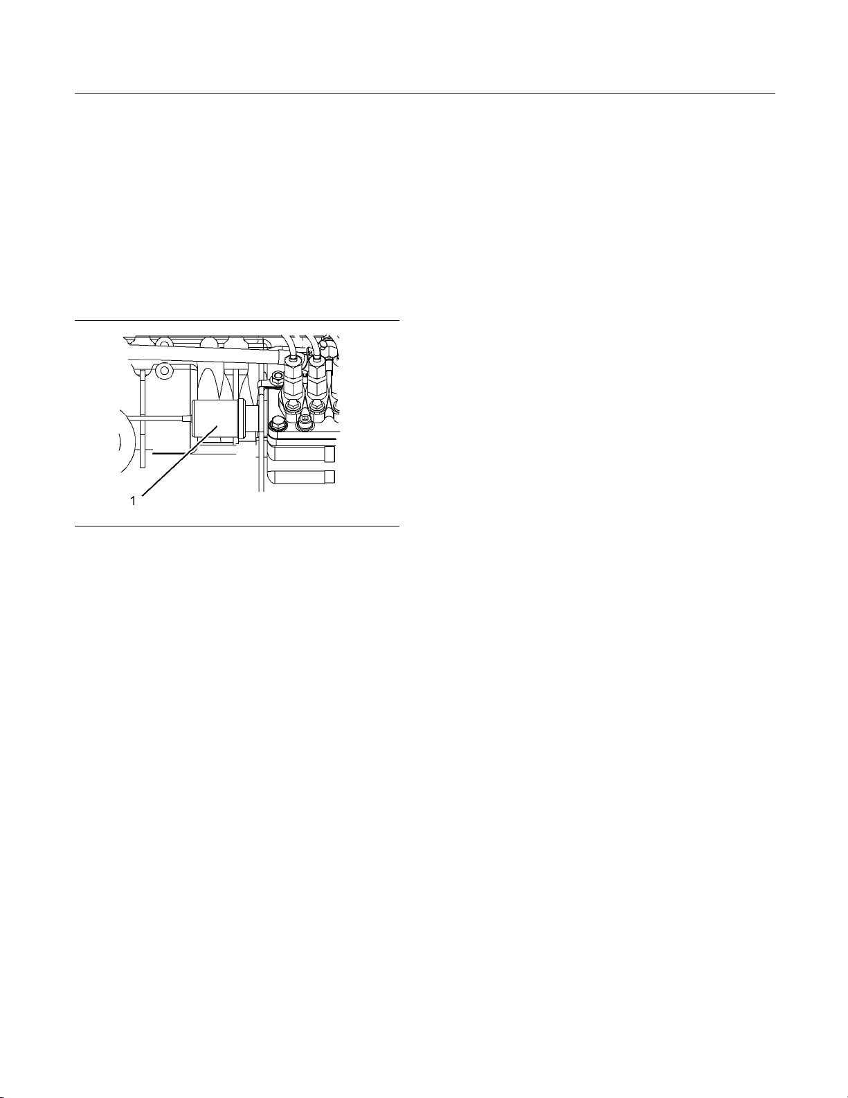
Fuel Shutoff
The fuel shutoff solenoid is located on the fuel
injection pump. When the fuel shutoff solenoid is
activated, the solenoid moves the fuel rack to the
“OFF” position.
Illustration 28
(1) Fuel shutoff solenoid
If an electronically controlled governor has been
installed the governor operates the fuel rack in order
to stop the engine.
g01305771
Page 30

30 SEBU8311-01
This document has been printed from SPI². Not for Resale
Operation Section
Engine Starting
Engine Starting
i02194223
Before Starting Engine
Before the en
daily maintenance and any other periodic
maintenance that is due. Refer to the Operation
and Maintena
Schedule” for more information.
For the maxim
•
thorough inspection within the engine compartment
before the engine is started. Look for the following
items: oil l
excessive dirt and/or grease. Remove any excess
dirt and/or grease buildup. Repair any faults that
were ident
Inspect the cooling system hoses for cracks and
•
for loose c
Inspect the alternator and accessory drive belts for
•
cracks, br
Inspect the wiring for loose connections and for
•
worn wires
Check the fuel supply. Drain water from the water
•
separator
(if equipped).
All valve
and during engine operation to help prevent high fuel
pressure. High fuel pressure may cause filter housing
failure o
gine is started, perform the required
nce Manual, “Maintenance Interval
um service life of the engine, make a
eaks, coolant leaks, loose bolts, and
ified during the inspection.
lamps.
eaks, and other damage.
or frayed wires.
(if equipped). Open the fuel supply valve
NOTICE
s in the fuel return line must be open before
r other damage.
Do not start the
•
if there is a “DO NOT OPERATE” warning tag or
similar warning tag attached to the start switch or
to the control
Ensure that the areas around the rotating parts are
•
clear.
All of the guards must be put in place. Check for
•
damaged guar
any damaged guards. Replace damaged guards
and/or missing guards.
Disconnect any battery chargers that are not
•
protected against the high current drain that
is created wh
engaged. Check electrical cables and check the
battery for poor connections and for corrosion.
Reset all of the shutoffs or alarm components (if
•
equipped).
Check the engine lubrication oil level. Maintain the
•
oil level between the “ADD” mark and the “FULL”
mark on the
Check the coolant level. Observe the coolant level
•
in the head
coolant level to the “FULL” mark on the header
tank.
If the engine is not equipped with a header tank
•
maintain the coolant level within 13 mm (0.5 inch)
of the bott
equipped with a sight glass, maintain the coolant
level in the sight glass.
Observe the air cleaner service indicator (if
•
equipped). Service the air cleaner when the yellow
diaphrag
piston locks in the visible position.
m enters the red zone, or when the red
engine or move any of the controls
s.
ds or for missing guards. Repair
en the electric starting motor is
engine oil level gauge.
er tank (if equipped). Maintain the
om of the filler pipe. If the engine is
If the engine has not been started for several weeks,
fuel may h
may have entered the filter housing. Also, when fuel
filters have been changed, some air pockets will be
trapped
fuel system. Refer to the Operation and Maintenance
Manual, “Fuel System - Prime” for more information
on primi
Engine exhaust contains products of combustion
which may be harmful to your health. Always start
and ope
and, if in an enclosed area, vent the exhaust to the
outside.
ave drained from the fuel system. Air
in the engine. In these instances, prime the
ng the fuel system.
rate the engi ne in a well ventilated area
Ensure t
•
engine has been disengaged from the engine.
Minimize electrical loads or remove any electrical
loads.
Startin
Do not use aerosol types of starting aids such as
ether. Such use could result i n an explosion and
personal injury.
hat any equipment that is driven by the
g the Engine
i02665533
Page 31

SEBU8311-01 31
This document has been printed from SPI². Not for Resale
Operation Section
Engine Starting
Refer to the OEM
Use the following procedure to start the engine.
1. Move the throt
before you start the engine.
Do not operate
onds at one time. Damage to the glow plugs could occur.
2. Turn the engin
Hold the engine start switch in the HEAT position
for 6 seconds until the glow plug indicator light
illuminates
aid in the starting of the engine.
Do not crank t
Allow the electric starting motor to cool for two minutes
before cranking the engine again.
3. While the glow plug indicator light is illuminated,
turn the engine start switch to the START position
and crank th
4. When the engine starts, release the engine start
switch.
5. Slowly move the throttle lever to the low idle
position an
the Operation and Maintenance Manual, “After
Starting Engine” topic.
Note: If the glow plug indicator light illuminates
rapidly for 2 to 3 seconds, or if the glow plug indicator
light fail
start system. Do not use ether or other starting fluids
to start the engine.
s to illuminate, a malfunction exists in the cold
manual for your type of controls.
tle lever to the low idle position
NOTICE
theglowplugsformorethan60sec-
e start switch to the HEAT position.
. This will activate the glow plugs and
NOTICE
he engine for more than 30 seconds.
e engine.
dallowtheenginetoidle.Referto
i02177935
Starting with Jump Start
Cables
Improper jump start cable connections can cause
an explosion resulting in personal injury.
Prevent sparks near the batteries. Sparks could
cause vapors to explode. Do not allow jump start
cable ends to contact each other or the engine.
Note: If it is possible, first diagnose the reason
for the starting failure. Make any necessary
repairs. If the engine will not start only due to
the condition of the battery, either charge the
battery, or start the engine with jump start cables.
The condition of the battery can be rechecked
after the engine has been switched OFF.
NOTICE
Using a battery source with the same voltage as the
electric st
jump starting. The use of higher voltage will damage
the electrical system.
Do not reverse the battery cables. The alternator can
be damaged. Attach ground cable last and remove
first.
When using an external electrical source to start the
engine, tu
“OFF” position. Turn all electrical accessories OFF before attaching the jump start cables.
arting motor. Use ONLY equal voltage for
rn the generator set control switch to the
6. If the engine does not start, release the engine
start switch and allow the electric starting motor to
cool. The
7. Turn the engine start switch to the OFF position in
order to s
n, repeat steps 2 through step 5.
top the engine.
Ensure that the main power switch is in the OFF position before attaching the jump start cables to the engine bein
1. Turn the start switch to the OFF position. Turn off
2. Connect one positive end of the jump start cable
gstarted.
all the en
to the pos
battery. Connect the other positive end of the jump
start cable to the positive cable terminal of the
electri
gine’s accessories.
itive cable terminal of the discharged
cal source.
Page 32

32 SEBU8311-01
This document has been printed from SPI². Not for Resale
Operation Section
Engine Starting
3. Connect one neg
to the negative cable terminal of the electrical
source. Connect the other negative end of the
jump start cab
chassis ground. This procedure helps to prevent
potential sparks from igniting the combustible
gases that ar
4. Start the engine.
5. Immediately after the stalled engine is started,
disconnect the jump start cables in reverse order.
After jump starting, the alternator may not be able to
fully recharge batteries that are severely discharged.
The batterie
correct voltage with a battery charger after the engine
is stopped. Many batteries which are considered
unusable ar
and Maintenance Manual, “Battery - Replace” and
Testing and Adjusting Manual, “Battery - Test”.
s must be replaced or charged to the
e still rechargeable. Refer to Operation
ative end of the jump start cable
le to the engine block or to the
e produced by some batteries.
i01903609
After Starting Engine
Note: In temperatures from 0 to 60°C (32 to 140°F),
the warm-up time is approximately three minutes. In
temperatures below 0°C (32°F), additional warm-up
time may be required.
When the engine idles during warm-up, observe the
following conditions:
Check for any fluid or for any air leaks at idle rpm
•
and at one-half full rpm (no load on the engine)
before operating the engine under load. This is not
possible in some applications.
Operate the engine at low idle until all systems
•
achieve operating temperatures. Check all gauges
during the warm-up period.
Note: Gauge readings should be observed and
the data should be recorded frequently while the
engine is operating. Comparing the data over time
will help to determine normal readings for each
gauge.Comparingdataovertimewillalsohelp
detect abnormal operating developments. Significant
changes in the readings should be investigated.
Page 33

SEBU8311-01 33
This document has been printed from SPI². Not for Resale
Operation Section
Engine Operation
Engine Operation
i02176671
Engine Operation
Correct oper
in obtaining the maximum life and economy of
the engine. If the directions in the Operation and
Maintenance
minimized and engine service life can be maximized.
The engine ca
engine reaches operating temperature. The engine
will reach normal operating temperature sooner
during a low
power demand. This procedure is more effective than
idling the engine at no load. The engine should reach
operating
Gauge readings should be observed and the data
should be r
is operating. Comparing the data over time will
help to determine normal readings for each gauge.
Comparing
abnormal operating developments. Significant
changes in the readings should be investigated.
ation and maintenance are key factors
Manual are followed, costs can be
n be operated at the rated rpm after the
engine speed (rpm) and during a low
temperature in a few minutes.
ecorded frequently while the engine
data over time will also help detect
i02330149
Fuel Conservation Prac tices
The efficiency o
economy. Perkins design and technology in
manufacturing provides maximum fuel efficiency in
all applicati
in order to attain optimum performance for the life
of the engine.
Avoid spilling fuel.
•
Fuel expands
may overflow from the fuel tank. Inspect fuel lines for
leaks. Repair the fuel lines, as needed.
Be aware of the properties of the different fuels.
•
Use only the recommended fuels.
Avoid unnecessary idling.
•
Shut off the
time.
Observe the
•
Keep the air cleaner elements clean.
Maintain th
•
f the engine can affect the fuel
ons. Follow the recommended procedures
when the fuel is warmed up. The fuel
engine rather than idle for long periods of
air cleaner service indicator frequently.
e electrical systems.
One damaged battery cell will overwork the alternator.
This will co
Ensure that the drive belts are correctly adjusted.
•
The drive be
Ensure that all of the connections of the hoses are
•
tight. The
Ensure that the driven equipment is in good
•
working or
Cold engines consume excess fuel. Utilize heat
•
from the j a
system, when possible. Keep cooling system
components clean and keep cooling system
component
engine without water temperature regulators.
All of these items will help maintain operating
temperat
nsume excess power and excess fuel.
lts should be in good condition.
connections should not leak.
der.
cket water system and the exhaust
s in good repair. Never operate the
ures.
Page 34

34 SEBU8311-01
This document has been printed from SPI². Not for Resale
Operation Section
Engine Stopping
Engine Stopping
i02334873
Stopping the Engine
NOTICE
Stopping the engine immediately after it has been
working under load, can result in overheating and accelerated wear of the engine components.
Avoid accelerating the engine prior to shutting it down.
Avoiding hot engine shutdowns will maximize turbocharger shaft and bearing life.
Note: Individual applications will have different
control systems. Ensure that the shutoff procedures
are understood. Use the following general guidelines
in order to stop the engine.
1. Remove the load from the engine. Reduce the
engine speed (rpm) to low idle. Allow the engine
to idle for five minutes in order to cool the engine.
2. Stop the engine after the cool down period
according to the shutoff system on the engine and
turn the ignition key switch to the OFF position.
If necessary, refer to the instructions that are
provided by the OEM.
i02176672
After Stopping Engine
Note: Before yo
the engine for at least 10 minutes in order to allow
the engine oil to return to the oil pan.
Check the crankcase oil level. Maintain the oil level
•
between the “MIN” mark and the “MAX” mark on
the engine oil
If necessary, perform minor adjustments. Repair
•
any leaks and
If the engine is equipped with a service hour meter,
•
note the read
is in the Operation and Maintenance Manual,
“Maintenance Interval Schedule”.
Fill the fuel tank in order to help prevent
•
accumulation of moisture in the fuel. Do not overfill
the fuel tan
Only use antifreeze/coolant mixtures recommended in
the Coolant Specifications that are in the Operation
and Mainten
engine damage.
Allow the en
•
u check the engine oil, do not operate
level gauge.
tighten any loose bolts.
ing. Perform the maintenance that
k.
NOTICE
ance Manual. Failure to do so can cause
gine to cool. Check the coolant level.
i01903586
Emergency
Emergency shutoff controls are for EMERGENCY use
ONLY. DO NOT use emergency shutoff devices or
controls for normal stopping procedure.
The OEM may have equipped the application with
an emergency stop button. For more information
about the emergency stop button, refer to the OEM
information.
Ensure that any components for the external system
that support the engine operation are secured after
the engine is stopped.
Stopping
NOTICE
If freezing temperatures are expected, check
•
the coolan
cooling system must be protected against freezing
to the lowest expected outside temperature. Add
the correc
Perform all required periodic maintenance on all
•
driven equ
the instructions from the OEM.
t for correct antifreeze protection. The
t coolant/water mixture, if necessary.
ipment. This maintenance is outlined in
Page 35

SEBU8311-01 35
This document has been printed from SPI². Not for Resale
Operation Section
Cold Weather Operation
Cold Weather Operation
i02717265
Cold Weather Operation
Perkins Diesel Engines can operate effectively in
cold weather. During cold weather, the starting and
the operation of the diesel engine is dependent on
the following items:
The type of fuel that is used
•
The viscosity of the engine oil
•
The operation of the glow plugs
•
Optional Cold starting aid
•
Battery condition
•
This section will cover the following information:
Potential problems that are caused by cold weather
•
operation
Suggest steps which can be taken in order to
•
minimize starting problems and operating problems
when the ambient air temperature is between
0° to−40 °C (32° to 40 °F).
Install the cor
•
before the beginning of cold weather.
Check all rubb
•
weekly.
Check all elec
•
fraying or damaged insulation.
Keep all batte
•
Fill the fuel tank at the end of each shift.
•
Check the air cleaners and the air intake daily.
•
Check the air intake more often when you operate
in snow.
Ensure that the glow plugs are in working order.
•
Refer to Test
-Test”.
Personal injury or property damage can result
from alcohol or starting fluids.
Alcohol or starting fluids are h ighly flammable and
toxic and if improperly stored could result in injury
or property
rect specification of engine lubricant
er parts (hoses, fan drive belts, etc)
trical wiring and connections for any
ries fully charged and warm.
ing and Adjusting Manual, “Glow Plug
damage.
The operation and maintenance of an engine in
freezing temperatures is complex . This is because
of the following conditions:
Weather conditions
•
Engine applications
•
Recommendations from your Perkins dealer or
your Perkins distributor are based on past proven
practices. The information that is contained in
this section provides guidelines for cold weather
operation.
Hints for Cold Weather Operation
If the engine will start, operate the engine until a
•
minimum operating temperature of 81 °C (177.8 °F)
is achieved. Achieving operating temperature will
help prevent the intake valves and exhaust valves
from sticking.
The cooling system and the lubrication system
•
for the engine do not lose heat immediately upon
shutdown. This means that an engine can be shut
downforaperiodoftimeandtheenginecanstill
have the ability to start readily.
Do not use aerosol types of starting aids such as
ether. Such use could result i n an explosion and
personal injury.
Forjumpstartingwithcablesincoldweather,
•
refer to the Operation and Maintenance Manual,
“Starting with Jump Start Cables.” for instructions.
Viscosity of the Engine Lubrication
Oil
Correct engine oil viscosity is essential. Oil viscosity
affects the amount of torque that is needed to
crank the engine. Refer to this Operation and
Maintenance Manual, “Fluid Recommendations” for
the recommended viscosity of oil.
Recommendations for the Coolant
Provide cooling system protection for the lowest
expected outside temperature. Refer to this Operation
and Maintenance Manual, “Fluid Recommendations”
for the recommended coolant mixture.
Page 36

36 SEBU8311-01
This document has been printed from SPI². Not for Resale
Operation Section
Cold Weather Operation
In cold weather
correct glycol concentration in order to ensure
adequate freeze protection.
, check the coolant often for the
Engine Block Heaters
Engine block h
engine jacket water that surrounds the combustion
chambers. This provides the following functions:
Startability is improved.
•
Warm up time i
•
An electric block heater can be activated once
the engine is
is typically a 1250/1500 W unit. Consult your
Perkins dealer or your Perkins distributor for more
information
Idling the E
When idling after the engine is started in cold
weather, in
rpm. This will warm up the engine more quickly.
Maintaining an elevated low idle speed for extended
periods wil
throttle. The engine should not be “raced” in order to
speed up the warm up process.
While the engine is idling, the application of a light
load (parasitic load) will assist in achieving the
minimum op
operating temperature is 82 °C (179.6 °F).
eaters (if equipped) heat the
s reduced.
stopped. An effective block heater
.
ngine
crease the engine rpm from 1000 to 1200
l be easier with the installation of a hand
erating temperature. The minimum
Recommendations for Cool ant
Warm Up
Warm up an engine that has cooled below normal
operatin
be performed before the engine is returned to full
operation. During operation in very cold temperature
conditio
result from engine operation for short intervals. This
can happen if the engine is started and the engine is
stopped
to warm up completely.
When the
temperatures, fuel and oil are not completely burned
in the combustion chamber. This fuel and oil causes
soft ca
Generally, the deposits do not cause problems and
the deposits are burned off during operation at
normal
When the engine is started and the engine is stopped
many ti
up completely, the carbon deposits become thicker.
This can cause the following problems:
g temperatures due to inactivity. This should
ns, damage to engine valve mechanisms can
many times without being operated in order
engine is operated below normal operating
rbon deposits to form on the valve stems.
engine operating temperatures.
mes without being operated in order to warm
Free operation
•
Valves become stuck.
•
Pushrods may become bent.
•
Other damage t
•
result.
For this reaso
the engine must be operated until the coolant
temperature is 71 °C (160 °F) minimum. Carbon
deposits on t
and the free operation of the valves and the valve
components will be maintained.
In addition, the engine must be thoroughly warmed in
order to keep other engine parts in better condition
and the servi
extended. Lubrication will be improved. There will be
less acid and less sludge in the oil. This will provide
longer serv
rings, and other parts. However, limit unnecessary
idle time to ten minutes in order to reduce wear and
unnecessa
of the valves is prevented.
o valve train components can
n, when the engine is started,
he valve stems will be kept at a minimum
celifeoftheenginewillbegenerally
ice life for the engine bearings, the piston
ry fuel consumption.
The Water Temperature Regulator and
Insulated
The engine is equipped with a water temperature
regulator
correct operating temperature jacket water circulates
through the engine cylinder block and into the
engine cy
cylinder block via an internal passage that bypasses
the valve of the coolant temperature regulator. This
ensures t
cold operating conditions. The water temperature
regulator begins to open when the engine jacket
water ha
temperature. As the jacket water coolant temperature
rises above the minimum operating temperature the
water te
more coolant through the radiator to dissipate excess
heat.
The progressive opening of the water temperature
regulator operates the progressive closing of the
bypass
head. This ensures maximum coolant flow to
the radiator in order to achieve maximum heat
pation.
dissi
Note: Perkins discourages the use of all air flow
iction devices such as radiator shutters.
restr
Restriction of the air flow can result in the following:
high exhaust temperatures, power loss, excessive
fan us
Heater Lines
. When the engine coolant is below the
linder head. The coolant then returns to the
hat coolant flows around the engine under
s reached the correct minimum operating
mperature regulator opens further allowing
passage between the cylinder block and
age, and reduction in fuel economy.
Page 37

SEBU8311-01 37
This document has been printed from SPI². Not for Resale
Operation Section
Cold Weather Operation
A cab heater is b
feed from the engine and the return lines from the
cab should be insulated in order to reduce heat loss
to the outside
eneficial in very cold weather. The
air.
Insulating the Air Inlet a nd Engine
Compartment
When temperatures below −18 °C (−0°F)willbe
frequently e
is located in the engine compartment may be
specified. An air cleaner that is located in the engine
compartment
into the air cleaner. Also, heat that is rejected by the
engine helps to warm the intake air.
Additional heat can be retained around the engine by
insulating the engine compartment.
ncountered, an air cleaner inlet that
may also minimize the entry of snow
i02322217
Fuel and the Effect from Cold
Weather
Note: Only use grades of fuel that are recommended
by Perkins. Refer to this Operation and Maintenance
Manual, “Fluid Recommendations”.
The following fuels can be used in this series of
engine.
Group 1
•
Group 2
•
Group 3
•
Special Fuels
•
Perkins prefer only Group 1 and Group 2 fuels for
use in this series of engines.
Group 1 fuels are the preferred Group of Fuels for
general use by Perkins. Group 1 fuels maximize
engine life and engine performance. Group 1 fuels
are usually less available than Group 2 fuels.
Frequently, Group 1 fuels are not available in colder
climates during the winter.
Note: Group 2 fuels must have a maximum wear
scar of 650 micrometers (HFRR to ISO 12156-1).
Group 2 fuels are considered acceptable for issues
of warranty. This group of fuels may reduce the life
of the engine, the engine’s maximum power, and the
engine’s fuel efficiency.
When Group 2 die
components provide a means of minimizing problems
in cold weather:
Glow plugs (if equipped)
•
Engine coolan
•
option
Fuel heaters,
•
Fuel line insulation, which may be an OEM option
•
There are three major differences between Group
1 fuels and Group 2 fuels. Group 1 fuels have the
following di
A lower cloud point
•
A lower pour point
•
A higher ener
•
Note: Group 3 fuels reduce the life of the engine. The
use of Group 3
warranty.
Group3fuels
Aviation Kerosene Fuels.
Special fuel
The cloud point is a temperature that allows wax
crystals to
the fuel filters to plug.
The pour poi
will thicken. The diesel fuel becomes more resistant
to flow through fuel lines, fuel filters,and fuel pumps.
Be aware of these facts when diesel fuel is
purchased. Consider the average ambient air
temperatu
that are fueled in one climate may not operate well if
the engines are moved to another climate. Problems
can result
Before troubleshooting for low power or for poor
performan
Low temperature fuels may be available for engine
operatio
fuels limit the formation of wax in the fuel at low
temperatures.
For more information on cold weather operation, refer
to the Operation and Maintenance Manual, “Cold
Weather O
Cold Weather”.
fferent characteristics to Group 2 fuels.
s include Biofuel.
form in the fuel. These crystals can cause
re for the engine’s application. Engines
due to changes in temperature.
ce in the winter, check the fuel for waxing.
n at temperatures below 0 °C (32 °F). These
peration and Fuel Related Components in
sel fuels are used the following
t heaters, which may be an OEM
which may be an OEM option
gy per unit volume of fuel
fuelsisnotcoveredbythePerkins
include Low Temperature Fuels and
nt is the temperature when diesel fuel
Page 38

38 SEBU8311-01
This document has been printed from SPI². Not for Resale
Operation Section
Cold Weather Operation
i01903588
Fuel Related Components in
Cold Weather
Fuel Tanks
Condensation can form in partially filled fuel tanks.
Top off the fuel tanks after you operate the engine.
Fuel tanks should contain some provision for draining
water and sediment from the bottom of the tanks.
Some fuel tan
and sediment to settle below the end of the fuel
supply pipe.
Some fuel tanks use supply lines that take fuel
directly from the bottom of the tank. If the engine is
equipped wi
the fuel system filter is important.
ks use supply pipes that allow water
th this system, regular maintenance of
Drain the wa
tank at the following intervals: weekly, oil changes,
and refueling of the fuel tank. This will help prevent
water and/o
fuel storage tank and into the engine fuel tank.
ter and sediment from any fuel storage
r sediment from being pumped from the
Fuel Filters
It is possi
between the fuel tank and the engine fuel inlet. After
you change the fuel filter, always prime the fuel
system in o
system. Refer to the Operation and Maintenance
Manual in the Maintenance Section for more
informat
The micron rating and the location of a primary fuel
filter is i
primary fuel filter and the fuel supply line are the most
common components that are affected by cold fuel.
ble that a primary fuel filter is installed
rder to remove air bubbles from the fuel
ion on priming the fuel system.
mportant in cold weather operation. The
Fuel Heaters
Note: The OEM may equip the application with fuel
heaters. If this is the case, disconnect an electric type
of fuel h
overheating of the fuel. If the type of fuel heater is a
heat exchanger, the OEM should have included a
bypass f
operational during warm weather in order to prevent
overheating of the fuel.
eater in warm weather in order to prevent
or warm weather. Ensure that the bypass is
For more information about fuel heaters (if equipped),
refer to the OEM information.
Page 39

SEBU8311-01 39
This document has been printed from SPI². Not for Resale
Maintenance Section
Refill Capacities
Maintenance Section
Refill Capacities
i02959059
Refill Capaci ties
Lubrication System
The refill capacities for the engine crankcase
reflect the approximate capacity of the crankcase
or sump plus standard oil fi lters. Auxiliary oil filter
systems will require additional oil. Refer to the OEM
specifications for the capacity of the auxiliary oil filter.
Refer to the Operation and Maintenance Manual,
“Maintenance Section” for more information on
Lubricant Specifications.
402D-05 Engine
Table 11
402D-05 Engine
Refill Capacities
Compartment or System Minimum Maximum
Crankcase Oil Sump
Total Lubrication System
(1)
These values are the approximate capacities for the crankcase
oil sump wh ich includes the standard factory installed oil filt ers.
Engines with auxiliary oil filters will require additional oil. Refer
to the OEM specifications for the capacity of the auxiliary oil
filter.
(2)
The Total Lubrication System includes the capacity for the
Crankcase Oil Sump plus the capacity of factory installed oil
filters and other filters added to the lubrication system. Enter
the value for the capacity of the Total Lubrication System in
this row.
(1)
(2)
1.61 L
(1.7 qt)
2.01 L
(2.1 qt)
403D-07 Engine
Table 12
403C-07 Engine
Refill Capacities
Compartment or System Minimum Maximum
Crankcase Oil Sump
Total Lubrication System
(1)
These values are the approximate capacities for the crankcase
oil sump which includes the standard factory installed oil fi lters.
Engines with aux iliary oil filters will require additional oil. Refer
to the OEM specifications for the c apacity of the auxiliary oil
filter.
(2)
The Total Lubrication System includes the c apacity for the
Crankcase Oil Sump plus the capacity of factory installed oil
filters and other filters added to the lubrication system. Enter
the value for t he capacity of the Total Lubrication System in
this row.
(1)
(2)
2.35 L
(2.5 qt)
3.05 L
(3.2 qt)
403D-11 Engine
Table 13
403D-11 Engine
Refill Capacities
Compartment or System
Crankcase Oil Sump
Total Lubrication System
(1)
These values are the approximate capacities for the crankcase
oil sump which includes the standard factory installed oil fi lters.
Engines with aux iliary oil filters will require additional oil. Refer
to the OEM specifications for the c apacity of the auxiliary oil
filter.
(2)
The Total Lubrication System includes the c apacity for the
Crankcase Oil Sump plus the capacity of factory installed oil
filters and other filters added to the lubrication system. Enter
the value for t he capacity of the Total Lubrication System in
this row.
(1)
(2)
Minimum Maximum
3.4 L
(3.6 qt)
4.4 L
(4.6494
403D-15 and 403D-15T Engines
Table 14
403D-15 and 403D-15T Engines
Refill Capacities
Compartment or System
Crankcase Oil Sump
Total Lubrication System
(1)
These values are the approximate capacities for the crankcase
oil sump which includes the standard factory installed oil fi lters.
Engines with aux iliary oil filters will require additional oil. Refer
to the OEM specifications for the c apacity of the auxiliary oil
filter.
(2)
The Total Lubrication System includes the c apacity for the
Crankcase Oil Sump plus the capacity of factory installed oil
filters and other filters added to the lubrication system. Enter
the value for t he capacity of the Total Lubrication System in
this row.
(1)
(2)
Minimum Maximum
4.5 L
(4.8 qt)
6L
(6.3 qt)
qt)
Page 40

40 SEBU8311-01
This document has been printed from SPI². Not for Resale
Maintenance Section
Refill Capacities
403D-17 Engine
Table 15
403D-17 Engine
Refill Capaciti
Compartment or System
Crankcase Oil Sump
Total Lubrication System
(1)
These values are the approximate capacities for the crankcase
oil sump wh ich includes the standard factory installed oil filt ers.
Engines with auxiliary oil filters will require additional oil. Refer
to the OEM specifications for the capacity of the auxiliary oil
filter.
(2)
The Total Lubrication System includes the capacity for the
Crankcase Oil Sump plus the capacity of factory installed oil
filters and other filters added to the lubrication system. Enter
the value for the capacity of the Total Lubrication System in
this row.
(1)
(2)
es
Minimum Maximum
4.5 L
(4.8 qt)
6L
(6.3 qt)
404D-15 Engine
Table 16
404D-15 Engine
Refill Capacities
Compartment or System Minimum Maximum
Crankcase Oil Sump
Total Lubrication System
(1)
These values are the approximate capacities for the crankcase
oil sump wh ich includes the standard factory installed oil filt ers.
Engines with auxiliary oil filters will require additional oil. Refer
to the OEM specifications for the capacity of the auxiliary oil
filter.
(2)
The Total Lub
Crankcase O
filters and o
the value fo
this row.
ther filters added to the lubrication system. Enter
r the capacity of the Total Lubrication System in
(1)
(2)
rication System includes the capacity for the
il Sump plus the capacity of factory installed oil
3.9 L
(4.1211 qt)
5.6 L
(5.9175
qt)
404D-22, 404D-
22T and 404D-22TA
Engines
Table 17
404D-22, 404D-22T and 404D-22TA Engines
Refill Capacities
Compartment or System Minimum Maximum
Crankcase Oil Sump
Total Lubrication System
(1)
More than one style of sump may be used on these engines.
Use these values to estimate the refill capacity. Use the engine
oil level gauge to fill the engine to the correct oil level. Record
the result in this table. T hese values are the approximate
capacities for the Crankcase O il Sump which includes the
standard factory installed oil filters. Engines with auxiliary oil
filters will require additional o il. Refer to the OEM specifications
for the capacity of the auxiliary oil filter.
(2)
The Total Lubrication System includes the c apacity for the
Crankcase Oil Sump plus the capacity of factory installed oil
filters and other filters added to the lubrication system. Enter
the value for t he capacity of the Total Lubrication System in
this row.
(1)
(2)
8.9 L
(9.4 qt)
10.6 L
(11.2 qt)
Cooling System
To maintain the cooling system, the Total Cooling
System capacity must be known. The approximate
capacity is for the engine cooling system. External
System capacities will vary among applications.
Refer to the OEM specifications for the External
System capacity. This capacity information will be
needed in order to determine the amount of coolant
that is required for the Total Cooling System.
402D-05 Engine
Table 18
402D-05 Engine
Refill Capacities
Compartment or System
Engine Only
External System Per OEM
Total Cooling System
(1)
The External System includes a radiator or an expansion
tank with the following components: heat exchanger and
piping. Refer to the OEM specifications. Enter the value for the
capacity of the External S ystem in this row.
(2)
The Total Cooling System capacity includes the capacity of
the Engine plus the External Sys tem. Enter the value for the
capacity of the Total Cooling System in this row.
(1)
(2)
Liters
1.1 1.2
Quarts
Page 41

SEBU8311-01 41
This document has been printed from SPI². Not for Resale
Maintenance Section
Refill Capacities
403D-07 Engine
Table 19
403D-07 Engine
Refill Capaciti
Compartment or System
Engine Only
External System Per OEM
Total Cooling System
(1)
The External System includes a radiator or an expansion
tank w ith the following components: heat exchanger and
piping. Refer to the OEM specifications. Enter the value for the
capacity of the External System in this ro w.
(2)
The Total Cooling System capacity includes the ca pacity of
the Engine plus the External S ystem. Enter the value for the
capacity of the Total Cooling System in this row.
403D-11 Engin
Table 20
(1)
(2)
e
403D-11 Engine
Refill Capacit
Compartment or System
Engine Only
External System Per OEM
Total Cooling System
(1)
The External System includes a radiator or an expansion
tank w ith the following components: heat exchanger and
piping. Refer to the OEM specifications. Enter the value for the
capacity of the External System in this ro w.
(2)
The Total Cooling System capacity includes the ca pacity of
the Engine plus the External S ystem. Enter the value for the
capacity of the Total Cooling System in this row.
403D-15 and 4
(1)
(2)
03D-15T Engines
es
Liters
1.2 1.3
ies
Liters
1.9 2.0
Quarts
Quarts
404D-15 Engine
Table 22
404D-15 Engine
Refill Capaciti
Compartment or System
Engine Only
External System Per OEM
Total Cooling System
(1)
The External System includes a radiator or an expansion
tank with the following components: heat exchanger and
piping. Refer to the OEM specifications. Enter the value for the
capacity of the External S ystem in this row.
(2)
The Total Cooling System capacity includes the capacity of
the Engine plus the External Sys tem. Enter the value for the
capacity of the Total Cooling System in this row.
404D-22, 404D
(1)
(2)
-22T and 404D-22TA
es
Liters
2.4 2.5
Quarts
Engines
Table 23
404D-22,404D-22T and 404D-22TA Engines
Compartment or System Liters Quarts
Engine Only 3.6 3.8
External System Per OEM
Total Coolin
(1)
The External S
tank with the
piping. Refe
capacity of t
(2)
The Total Cooling System capacity includes the capacity for
the Engine plus the External Sys tem. Enter the value for the
capacity of the Total Cooling System in this row.
Refill Capacities
(1)
gSystem
r to the O E M specifications. Enter the value for the
he External System in this row.
(2)
ystem includes a radiator or an expansion
following components: heat exchanger and
Table 21
403D-15 and 403D-15TEngines
Refill Capaci
Compartment or System
Engine Only
External System Per OEM
Total Cooling System
(1)
The External System includes a radiator or an expansion
tank w ith the following components: heat exchanger and
piping. Refer to the OEM specifications. Enter the value for the
capacity of the External System in this ro w.
(2)
The Total Cooling System capacity includes the ca pacity of
the Engine plus the External S ystem. Enter the value for the
capacity of the Total Cooling System in this row.
(2)
ties
Liters
Quarts
2.6 2.7
(1)
Fluid Recommendations
General Lubricant Inform a tion
Because of go
certification of exhaust emissions from the engine,
the lubricant recommendations must be followed.
Engine Manufacturers Association (EMA)
Oils
vernment regulations regarding the
The “Engine Manufacturers Association
Recommended Guideline on Diesel Engine Oil” is
recognize
d by Perkins. For detailed information
about this guideline, see the latest edition of EMA
publication, “EMA DHD -1”.
i02959104
Page 42

42 SEBU8311-01
This document has been printed from SPI². Not for Resale
Maintenance Section
Refill Capacities
API Oils
The Engine Oil Licensing and Certification System by
theAmericanP
etroleum Institute (API) is recognized
by Perkins. For detailed information about this
system, see the latest edition of the “API publication
No. 1509”. En
gine oils that bear the API symbol are
authorized by API.
Illustration 29
Typical API symbol
g00546535
Diesel engine oils CC, CD, CD-2, and CE have
not been API authorized classifications since 1
January 1996. Table 24 summarizes the status of
the classifications.
Table 24
API Classifications
Current Obsolete
CF-4, CG-4, CH-4 CE
CF CC, CD
(1)
CF-2
(1)
The classifications CD-2 and American Petroleum Institute
CF-2 are for two-cycle diesel engines. Perkins does not sell
engines that utilize CD-2 and API CF-2 oils.
CD-2
(1)
Termin olo gy
Certain abbreviations follow the nomenclature of
“SAE J754”. Some classifications follow “SAE J183”
abbreviations, and some classifications follow the
“EMA Recommended Guideline on Diesel Engine
Oil”. In addition to Perkins definitions, there are other
definitions that will be of assistance in purchasing
lubricants. Recommended oil viscosities can be found
in this publication, “Fluid Recommendations/Engine
Oil” topic (Maintenance Section).
Engine Oil
Commercial Oils
The performance of commercial diesel engine
oils is based on American Petroleum Institute
(API) classifications. These API classifications are
developed in order to provide commercial lubricants
for a broad range of diesel engines that operate at
various conditions.
Only use commercial oils that meet the following
classifications:
EMA DHD-1 multigrade oil (pre ferred oil)
•
API CH-4 multigrade oil (preferred oil)
•
ACEAE5
•
In order to make the correct choice of a commercial
oil, refer to the following explanations:
EMA DHD-1 – The Engine Manufacturers
Association (EMA) has developed lubricant
recommendations as an alternative to the API oil
classification system. DHD-1 is a Recommended
Guideline that defines a level of oil performance for
these types of diesel engines: high speed, four stroke
cycle, heavy-duty, and light duty. DHD-1 oils may
be used in Perkins engines when the following oils
are recommended: API CH-4, API CG-4, and API
CF-4. DHD-1 oils are intended to provide superior
performance in comparison to API CG-4 and API
CF-4.
DHD-1 oils will meet the needs of high performance
Perkins diesel engines that are operating in many
applications. The tests and the test limits that are
used to define DHD-1 are similar to the new API
CH-4 classification. Therefore, these oils will also
meet the requirements for diesel engines that require
low emissions. DHD-1 oils are designed to control the
harmful effects of soot with improved wear resistance
and improved resistance to plugging of the oil filter.
These oils will also provide superior control of piston
deposits for engines with either two-piece steel
pistons or aluminum pistons.
All DHD-1 oils must complete a full test program
with the base stock and with the viscosity grade of
the finishedcommercialoil.Theuseof“APIBase
Oil Interchange Guidelines” are not appropriate for
DHD-1 oils. This feature reduces the variation in
performance that can occur when base stocks are
changed in commercial oil formulations.
Page 43

SEBU8311-01 43
This document has been printed from SPI². Not for Resale
Maintenance Section
Refill Capacities
DHD-1 oils are r
change interval programs that optimize the life of the
oil. These oil change interval programs are based
on oil analysi
conditions that demand a premium oil. Your Perkins
dealer or your Perkins distributor has the specific
guidelines f
API CH-4 – API CH-4 oils were developed in order to
meet the requ
diesel engines. Also, the oil was designed to
meet the requirements of the low emissions diesel
engines. AP
in older diesel engines and in diesel engines that
usehighsulfurdieselfuel.APICH-4oilsmaybe
used in Perk
CF-4 oils. API CH-4 oils will generally exceed the
performance of API CG-4 oils in the following criteria:
deposits o
of piston rings, valve train wear, viscosity control,
and corrosion.
Three new engine tests were developed for the API
CH-4 oil. The firsttestspecifically evaluates deposits
on piston
This test (piston deposit) also measures the control
of oil consumption. A second test is conducted
with mode
the following criteria: wear of piston rings, wear of
cylinder liners, and resistance to corrosion. A third
new test
high levels of soot in the oil: wear of the valve train,
resistance of the oil in plugging the oil filter, and
control
In addition to the new tests, API CH-4 oils have
toughe
generate high soot. The oils also have improved
oxidation resistance. API CH-4 oils must pass an
additi
aluminum pistons (single piece). Oil performance is
also established for engines that operate in areas
with h
s for engines with the two-piece steel piston.
measures the following characteristics with
of sludge.
r limits for viscosity control in applications that
onal test (piston deposit) for engines that use
igh sulfur diesel fuel.
ecommended for use in extended oil
s. DHD-1 oils are recommended for
or optimizing oil change intervals.
irements of the new high performance
I CH-4 oils are also acceptable for use
ins engines that use API CG-4 and API
n pistons, control of oil consumption, wear
rate oil soot. The second test measures
NOTICE
Failuretofoll
shortened engine service life due to deposits and/or
excessive wear.
Total Base Nu m
ow these oil recommendations can cause
ber (TBN) and Fuel Sulfur
Levels for Diesel Engines
The Total Base
the fuel sulfur level. For engines that use distillate
fuel, the minimum TBN of the new oil must be
10 times the f
by “ASTM D2896”. The minimum TBN of the oil
is 5 regardless of fuel sulfur level. Illustration 30
demonstrate
Illustration 30
(Y) TBN by “ASTM D2896”
(X) Percentage of fuel sulfur by weight
(1) TBN of new oil
(2) Change the oil when the TBN deteriorates to 50 percent of
the original TBN.
Use the following guidelines for fuel sulfur levels that
exceed 1.5 percent:
Choose an oil with the highest TBN that meets one
•
of these classifications: EMA DHD-1 and API CH-4.
Number (TBN) for an oil depends on
uel sulfur level. The TBN is defined
stheTBN.
g00799818
All of these improvements allow the API CH-4
achieve optimum oil change intervals. API
oil to
CH-4 oils are recommended for use in extended oil
change intervals. API CH-4 oils are recommended
nditions that demand a premium oil. Your
for co
Perkins dealer or your Perkins distributor has specific
guidelines for optimizing oil change intervals.
Some commercial oils that meet the API
classifications may require reduced oil change
rvals. To determine the oil change interval, closely
inte
monitor the condition of the oil and perform a wear
metal analysis.
Reduce the oil change interval. Base the oil
•
change interval on the oil analysis. Ensure that the
oil analysis includes the condition of the oil and a
wear metal analysis.
Excessive piston deposits can be produced by an oil
withahighTBN.Thesedepositscanleadtoaloss
of control of the oil consumption and to the polishing
of the cylinder bore.
NOTICE
Operating diesel engines with fuel sulphur levels over
0.5 percent will require shortened oil change intervals
in order to help maintain adequate wear protection.
Page 44

44 SEBU8311-01
This document has been printed from SPI². Not for Resale
Maintenance Section
Refill Capacities
Table 25
Percentage of Sulfur in
the fuel
Lower than 0.5 Normal
0.5 to 1.0
Greater than 1.0 0.50 of normal
Oil change interval
0.75 of normal
Lubricant Viscosity Recommendations
The correct SAE viscosity grade of oil is determined
by the minimum ambient temperature during
cold engine start-up, and the maximum ambient
temperature during engine operation.
Refer to Table 26 (minimum temperature) in order
to determine the required oil viscosity for starting a
cold engine.
Refer to Table 26 (maximum temperature) in order
to select the oil viscosity for engine operation at the
highest ambient temperature that is anticipated.
Generally, use the highest oil viscosity that is
available to meet the requirement for the temperature
at start-up.
Table 26
Engine Oil Viscosity
EMA LRG-1
API CH-4
Viscosity Grade
SAE 0W20 −40 °C (−40 °F) 10 °C (50 °F)
SAE 0W30 −40 °C (−40 °F) 30 °C (86 °F)
SAE 0W40 −40 °C (−40 °F) 40 °C (104 °F)
SAE 5W30 −30 °C (−22 °F) 30 °C (86 °F)
SAE 5W40 −30 °C (−22 °F) 40 °C (104 °F)
SAE 10W30 −20 °C (−4 °F) 40 °C (104 °F)
SAE 15W40 −10 °C (14 °F) 50 °C (122 °F)
Ambient Temperature
Minimum Maximum
Synthetic Base Stock Oils
Synthetic
these engines if these oils meet the performance
requirements that are specified for the engine.
Synthetic base oils generally perform better than
conventional oils in the following two areas:
Synthetic base oils have improved flow at low
•
temperatures especially in arctic conditions.
Synthetic base oils have improved oxidation
•
stability especially at high operating temperatures.
base oils are acceptable for use in
Some synthetic
characteristics that enhance the service life of the
oil. Perkins does not recommend the automatic
extending of t
oil.
Re-refined Ba
Re-refined base stock oils are acceptable for
use in Perkin
performance requirements that are specified by
Perkins. Re-refinedbasestockoilscanbeused
exclusively
new base stock oils. The US military specifications
and the specifications of other heavy equipment
manufactur
stock oils that meet the same criteria.
The process
stock oil should adequately remove all wear metals
that are in the used oil and all the additives that
areintheu
make re-refined base stock oil generally involves the
process of vacuum distillation and hydrotreating the
used oil. F
high quality, re-refined base stock oil.
Lubrican
When an engine is started and an engine is operated
in ambien
multigrade oils that are capable of flowinginlow
temperatures.
These oils have lubricant viscosity grades of SAE
0W or SAE 5W.
When an engine is started and operated in ambient
temperatures below −30 °C (−22 °F), use a synthetic
base sto
orwitha5Wviscositygrade.Useanoilwithapour
point that is lower than −50 °C (−58 °F).
The number of acceptable lubricants is limited in
cold weather conditions. Perkins recommends the
followi
First Choice – Use oil with an EMA DHD-1
Recomm
an API license. The oil should be either SAE 0W20,
SAE 0W30, SAE 0W40, SAE 5W30, or SAE 5W40
lubric
Second Choic e – Use an oil that has a CH-4
additi
tested for the requirements of the API license, the oil
must be either SAE 0W20, SAE 0W30, SAE 0W40,
SAE 5W
ck multigrade oil with an 0W viscosity grade
ng lubricants for use in cold weather conditions:
ended Guideline. Use a CH-4 oil that has
ant viscosity grade.
ve package. Although the oil has not been
30, or SAE 5W40.
base oils have performance
he oil change intervals for any type of
se Stock Oils
s engines if these oils meet the
in finished oil or in a combination with
ers also allow the use of re-refined base
that is used to make re-refined base
sed oil. The process that is used to
iltering is adequate for the production of
ts for Cold Weather
t temperatures below −20 °C (−4°F),use
Page 45

SEBU8311-01 45
This document has been printed from SPI². Not for Resale
Maintenance Section
Refill Capacities
NOTICE
Shortened engi
choice oils are used.
ne service life could result if second
Aftermarket O il Additives
Perkins does not recommend the use of aftermarket
additives in oil. It is not necessary to use aftermarket
additives in o
service life or rated performance. Fully formulated,
finished oils consist of base oils and of commercial
additive pac
blended into the base oils at precise percentages in
order to help provide finished oils with performance
characteris
There are no industry standard tests that evaluate
the performa
additives in finished oil. Aftermarket additives may
not be compatible with the finished oil’s additive
package, wh
finished oil. The aftermarket additive could fail to
mix with the finished oil. This could produce sludge
in the cran
aftermarket additives in finished oils.
rder to achieve the engine’s maximum
kages. These additive packages are
tics that meet industry standards.
nce or the compatibility of aftermarket
ich could lower the performance of the
kcase. Perkins discourages the use of
The Wear Rate An
•
engine’s metals. The amount of wear metal and
type of wear metal that is in the oil is analyzed. The
increase in th
oil is as important as the quantity of engine wear
metal in the oil.
Tests are conducted in order to detect
•
contamination of the oil by water, glycol or fuel.
The Oil Condition Analysis determines the loss of
•
the oil’s lubricating properties. An infrared analysis
is used to com
properties of the used oil sample. This analysis
allows technicians to determine the amount of
deteriorat
also allows technicians to verify the performance
of the oil according to the specification during the
entire oil c
ion of the oil during use. This analysis
hange interval.
alysis monitors the wear of the
e rate of engine wear metal in the
pare the properties of new oil to the
i02959102
Fluid Recommendations
(Coolant Specifications)
To achieve
engine, conform to the following guidelines:
Select the
•
the “EMA Recommended Guideline on Diesel
Engine Oil” or the recommended API classification.
See the appropriate “Lubricant Viscosities” table in
•
order to find the correct oil viscosity grade for your
engine.
At the specified interval, service the engine. Use
•
new oil an
Perform maintenance at the intervals that are
•
specified
Manual, “Maintenance Interval Schedule”.
Oil analy
Some engines may be equipped with an oil sampling
valve. I
is used to obtain samples of the engine oil. The oil
analysis will complement the preventive maintenance
program
The oil analysis is a diagnostic tool that is used to
determi
rates. Contamination can be identified and measured
through the use of the oil analysis. The oil analysis
includ
the best performance from a Perkins
correct oil, or a commercial oil that meets
dinstallanewoilfilter.
in the Operation and Maintenance
sis
f oil analysis is required the oil sampling valve
.
ne oil performance and component wear
es the following tests:
General Coolant Information
NOTICE
Never add coolant to an overheated engine. Engine
damage could result. Allow the engine to cool first.
NOTICE
If the engine is to be stored in, or shipped to an area
with below freezing temperatures, the cooling system
must be eit
ature or drained completely to prevent damage.
Frequently check the specific gravity of the coolant for
proper freeze protection or for anti-boil protection.
Clean the cooling system for the following reasons:
Contamina
•
Overheating of the engine
•
Foaming of the coolant
•
her protected to the lowest outside temper-
NOTICE
tion of the cooling system
Page 46

46 SEBU8311-01
This document has been printed from SPI². Not for Resale
Maintenance Section
Refill Capacities
Additives
NOTICE
Never operate a
regulators in the cooling system. Water temperature
regulators help to maintain the engine coolant at the
proper operat
lems can develop without water temperature regulators.
n engine without water temperature
ing temperature. Cooling system prob-
Additives help to protect the metal surfaces of
the cooling sy
insufficient amounts of additives enable the following
conditions to occur:
Corrosion
•
stem. A lack of coolant additives or
Many engine fa
system. The following problems are related to cooling
system failures: Overheating, leakage of the water
pump, and plu
These failures can be avoided with correct cooling
system maint
as important as maintenance of the fuel system and
the lubrication system. Quality of the coolant is as
important a
oil.
Coolant is n
Water, additives, and glycol.
ilures are related to the cooling
gged radiators or heat exchangers.
enance. Cooling system maintenance is
s the quality of the fuel and the lubricating
ormally composed of three elements:
Water
Water is used in the cooling system in order to
transfer he
Distilled water or deionized water is
recommend
DO NOT use the following types of water in cooling
systems: H
conditioned with salt, and sea water.
If distill
use water with the properties that are listed in T able
27.
Table 27
at.
ed for use in engine cooling systems.
ard water, softened water that has been
ed water or deionized water is not available,
Acceptabl
Property Maximum Limit
Chloride (Cl) 40 mg/L
Sulfate (SO4) 100 mg/L
Total Hardness 170 mg/L
Total Solids 340 mg/L
Acidity pH of 5.5 to 9.0
e Water
Formation of m
•
Rust
•
Scale
•
Foaming of the
•
Many additives are depleted during engine operation.
These additiv
Additives must be added at the correct concentration.
Overconcent
inhibitors to drop out-of-solution. The deposits can
enable the following problems to occur:
Formation of gel compounds
•
Reduction of
•
Leakage of the water pump seal
•
Plugging of radiators, coolers, and small passages
•
ineral deposits
coolant
es must be replaced periodically.
ration of additives can cause the
heat transfer
Glycol
Glycol in the coolant helps to provide protection
against the
Boiling
•
Freezing
•
Cavitation
•
For optimum performance, Perkins recommends a
1:1 mixture
Note: Use a mixture that will provide protection
against the
Note: 100 percent pure glycol will freeze at a
temperatu
following conditions:
of the water pump
of a water/glycol solution.
lowest ambient temperature.
re of −23 °C (−9°F).
For a water analysis, consult one of the following
sources:
Local water utility company
•
Agricultural agent
•
Independent laboratory
•
Most conventional antifreezes use ethylene glycol.
Propylene
with water, ethylene and propylene glycol provide
similar protection against freezing and boiling. See
Tables 28 a
glycolmayalsobeused.Ina1:1mixture
nd 29.
Page 47

SEBU8311-01 47
This document has been printed from SPI². Not for Resale
Maintenance Section
Refill Capacities
Table 28
Ethylene Glycol
Concentration Freeze Protection
50 Percent −36 °C (−33 °F)
60 Percent
−51 °C (−60 °F)
NOTICE
Do not use propylene glycol in concentrations that exceed 50 percent glycol because of propylene glycol’s
reduced heat transfer capability. Use ethylene glycol
in conditions that require additional protection against
boiling or freezing.
Table 29
Propylene Glycol
Concentration Freeze Protection
50 Percent −29 °C (−20 °F)
To check the concentration of glycol in the coolant,
measure the specific gravity of the coolant.
Coolant Recommendations
ELC____________________________ Extended Life Coolant
•
In stationary e
ngine applications and marine engine
applications that do not require anti-boil protection
or freeze protection, a mixture of SCA and water
is acceptable
. Perkins recommends a six percent
to eight percent concentration of SCA in those
cooling systems. Distilled water or deionized water
is preferred
. Water which has the recommended
properties may be used.
Table 30
Coolant Service Life
Coolant Type Service Life
Perkins ELC
Commercial Heavy-Duty
Antifreeze t
“ASTM D4985”
Perkins POWERPART
Commercial SCA and
hat meets
SCA
Water
6,000 Service Hours or
Three Years
3000 Service Hours or
Two Years
3000 Service Hours or
Two Years
3000 Service Hours or
Two Years
ELC
Perkins provides ELC for use in the following
applications:
SCA___________________Supplement Coolant Additive
•
ASTM__________________________________________ American
•
Society for Testing and Materials
The following two coolants are used in Perkins diesel
engines:
Preferred – Perkins ELC
Acceptable – A commercial heavy-duty antifreeze
that meets “ASTM D4985” specifications
NOTICE
Do not use a commercial coolant/antifreeze that only meets the ASTM D3306 specification. This type of
coolant/antifreeze is made for light automotive applications.
Perkins recommends a 1:1 mixture of water and
glycol. This mixture of water and glycol will provide
optimum heavy-duty performance as a antifreeze.
Thisratiomaybeincreasedto1:2watertoglycolif
extra freezing protection is required.
Note: A commercial heavy-duty antifreeze that
meets “ASTM D4985” specifications MAY require a
treatment with an SCA at the initial fill. Read the label
or the instructions that are provided by the OEM of
the product.
Heavy-duty spark ignited gas engines
•
Heavy-duty diesel engines
•
Automotive applications
•
The anti-corrosion package for ELC is different from
the anti-corrosion package for other coolants. ELC
is an ethylene glycol base coolant. However, ELC
contains organic corrosion inhibitors and antifoam
agents with low amounts of nitrite. Perkins ELC
has been formulated with the correct amount of
these additives in order to provide superior corrosion
protection for all metals in engine cooling systems.
ELC is available in a 1:1 premixed cooling solution
with distilled water. The Premixed ELC provides
freeze protection to −36 °C (−33 °F). The Premixed
ELC is recommended for the initial fill of the cooling
system. The Premixed ELC is also recommended for
topping off the cooling system.
Containers of several sizes are available. Consult
your Perkins distributor for the part numbers.
Page 48

48 SEBU8311-01
This document has been printed from SPI². Not for Resale
Maintenance Section
Refill Capacities
ELC Cooling System Maintenance
NOTICE
Correct additions to the Extended Life
Coolant
NOTICE
Use only Perkins products for pre-mixed or concentrated coolants.
Mixing Extended Life Coolant with other products reduces the Extended Life Coolant service life. Failure to
follow the re
tem components life unless appropriate corrective action is performed.
In order to maintain the correct balance between
the antifreeze and the additives, you must maintain
the recommended concentration of ELC. Lowering
the proportion of antifreeze lowers the proportion of
additive. This will lower the ability of the coolant to
protect the system from pitting, from cavitation, from
erosion, and from deposits.
Do not use a conventional coolant to top-off a cooling
system tha
Do not use standard supplemental coolant additive
(SCA).
When using Perkins ELC, do not use standard SCA’s
or SCA filte
commendations can reduce cooling sys-
NOTICE
tisfilled with Extended Life Coolant (ELC).
rs.
ELC Cooling System Cleaning
Note: If th
cleaning agents are not required to be used at
the specified coolant change interval. Cleaning
agents ar
contaminated by the addition of some other type of
coolant or by cooling system damage.
e cooling system is already using ELC,
e only required if the system has been
Care must b e tak
contained during performance of inspection, maintenance, testing, adjusting and the repair of the
product. Be pr
containers before opening any compartment or disassembling any component containing fluids.
Dispose of all fluids according to local regulations and
mandates.
1. Drain the cool
2. Dispose of the coolant according to local
regulations
3. Flush the system with clean water in order to
remove any de
4. Use Perkins cleaner to clean the system. Follow
the instruct
5. Drain the cleaner into a suitable container. Flush
the cooling
6. Fill the cooling system with clean water and
operate the
49° to 66°C (120° to 150°F).
Incorrect o
can result in damage to copper and other metal components.
To avoid damage to the cooling system, make sure to
completely flush the cooling system with clear water.
Continue t
cleaning agent are gone.
7. Drain the c
and flushthecoolingsystemwithcleanwater.
r incomplete flushing of the cooling system
o flush the system until all the signs of the
en to ensure that all fluids are
epared to collect the fluid with suitable
ant into a suitable container.
.
bris.
ion on the label.
system with clean water.
engine until the engine is warmed to
NOTICE
ooling system into a suitable container
Clean water is the only cleaning agent that is required
when ELC is drained from the cooling system.
Before the cooling system is filled, the heater control
(if equipped) must be set to the hot position. Refer
to the OE
the cooling system is drained and the cooling system
is refilled, operate the engine until the coolant level
reaches
until the coolant level stabilizes. As needed, add
thecoolantmixtureinordertofill the system to the
specifi
M in order to set the heater control. After
the normal operating temperature and
ed level.
Note: The c
flushed from the cooling system. Cooling system
cleaner that is left in the system will contaminate the
coolant. T
system.
8. Repeat St
completely clean.
9. Fill the c
ELC.
ooling system cleaner must be thoroughly
he cleaner may also corrode the cooling
eps6and7untilthesystemis
oolingsystemwiththePerkinsPremixed
Changing to Perkins ELC
To change from heavy-duty antifreeze to the Perkins
ELC, perform the following steps:
Page 49

SEBU8311-01 49
This document has been printed from SPI². Not for Resale
Maintenance Section
Refill Capacities
ELC Cooling Sys
Mixing ELC with other products reduces the effectiveness of the ELC and shortens the ELC service life.
Use only Perkins Products for premixed or concentrate coolants. Failure to follow these recommendations can result in shortened cooling system component life.
ELC cooling systems can withstand contamination to
a maximum of ten percent of conventional heavy-duty
antifreeze or SCA. If the contamination exceeds ten
percent of the total system capacity, perform ONE of
the following procedures:
Drain the cooling system into a suitable container.
•
Dispose of the coolant according to local
regulations. Flush the system with clean water. Fill
the system with the Perkins ELC.
Drain a portion of the cooling system into a suitable
•
container according to local regulations. Then, fill
the cooling system with premixed ELC. This should
lower the contamination to less than 10 percent.
Maintain the system as a conventional Heavy-Duty
•
Coolant. Treat the system with an SCA. Change
the coolant at the interval that is recommended for
the conventional Heavy-Duty Coolant.
tem Contamination
NOTICE
Commercial Heavy -Duty Antifreeze and
SCA
NOTICE
Commercial Heavy-Duty Coolant which contains
Amine as pa
not be used.
Never operate an engine without water temperature
regulators in the cooling system. Water temperature
regulators help to maintain the engine coolant at the
correct operating temperature. Cooling system problems can develop without water temperature regulators.
Check the antifreeze (glycol concentration) in
order to ensure adequate protection against boiling
or freezing. Perkins recommends the use of a
refractometer for checking the glycol concentration.
Perkins engine cooling systems should be tested at
500 hour intervals for the concentration of SCA.
Additions of SCA are based on the results of the test.
An SCA that is liquid may be needed at 500 hour
intervals.
rt of the corrision protection system must
NOTICE
Refer to Table 3
of SCA.
Table 31
Part Number
21825735 10
1 for part numbers and for quantities
Perkins Liquid SCA
Quantity
Adding the SCA to Heavy-Duty Coolant
at the Initial Fill
Commercial heavy-duty antifreeze that meets “ASTM
D4985” specifications MAY require an addition of
SCA at the initial fill. Read the label or the instructions
that are provided by the OEM of the product.
Use the equation that is in Table 32 to determine the
amount of Perkins SCA that is required when the
cooling system is initially filled.
Table 32
Equation For Adding The SCA To The Heavy-Duty
V is the total volume of the cooling s ystem.
X is the amount of SCA that is required.
Table 33 is an example for using the equation that
is in Table 32.
Table 33
Example Of The Equation For Adding The SCA To
The Heavy-Duty Coolant At The Initial Fill
Total Vol u m e
of the Cooling
System (V)
15 L (4 US gal)
Coolant At The Initial Fill
V×0.045=X
Multiplication
Factor
×0.045
Amount of
SCA that is
Required (X)
0.7 L (24 oz)
Adding The SCA to The Heavy-Duty
Coolant For Maintenance
Heavy-duty antifreeze of all types REQUIRE periodic
additions of an SCA.
Test the antifreeze periodically for the concentration
of SCA. For the interval, refer to the Operation
and Maint
Schedule” (Maintenance Section). Test the
concentration of SCA.
Additions of SCA are based on the results of the
test. The size of the cooling system determines the
amount of
enance Manual, “Maintenance Interval
SCA that is needed.
Page 50

50 SEBU8311-01
This document has been printed from SPI². Not for Resale
Maintenance Section
Refill Capacities
Use the equatio
amount of Perkins SCA that is required, if necessary:
Table 34
Equation For Adding The SCA To The Heavy-Duty
V is the total volume of the cooling system.
X is the amount of SCA that is required.
Table35isanexampleforusingtheequationthat
is in Table 34.
Table 35
Example Of The
The Heavy-Duty Coolant For Maintenance
Total Vol u m e
of the Cooling
System (V)
15 L (4 US gal)
n that is in Table 34 to determine the
Coolant For Maintenance
V × 0.014 = X
Equation For Adding The SCA To
Multiplication
Factor
× 0.014
Amount of
SCA that is
Required (X)
0.2 L (7 oz)
Cleaning the System of Heavy-Duty
Antifreeze
LSD Low Sulfur D
•
ULSD Ultra Low Sulfur Diesel
•
RME Rape Methyl Ester
•
SME Soy Methyl
•
EPA Environmental Protection Agency of the
•
United States
General Infor
Every attempt i
information. By use of this document you agree that
Perkins Engines Company Limited is not responsible
forerrorsoro
These recommendations are subject to change without notice. Contact your local Perkins distributor for
the most up to date recommendations.
iesel
Ester
mation
NOTICE
smadetoprovideaccurate,uptodate
missions.
NOTICE
Diesel Fuel Requirements
Perkins cooling system cleaners are designed
to clean the cooling system of harmful scale
and corrosion. Perkins cooling system cleaners
dissolve mineral scale, corrosion products, light oil
contamination and sludge.
Clean the cooling system after used coolant is
•
drained or before the cooling system is filled with
new coolant.
Clean the cooling system whenever the coolant is
•
contaminated or whenever the coolant is foaming.
i02959101
Fluid Recommendations
(Fuel Specification)
Glossary
•
ISO International Standards Organization
•
ASTM American Society for Testing and Materials
•
Satisfactory
use of a good quality fuel. The use of a good quality
fuel will give the following results: long engine life and
acceptable e
meet the minimum requirements that are stated in
tables 36, 37 and 38.
The footnotes are a key part of the Perkins Specification for Distillate Diesel Fuel Table. Read ALL of the
footnotes.
engine performance is dependent on the
xhaust emissions levels. The fuel must
NOTICE
HFRR High F
•
Lubricity testing of diesel fuels
FAM E Fatt
•
CFR Co-ordinating Fuel Research
•
requency Reciprocating Rig for
y Acid Methyl Esters
Page 51

SEBU8311-01 51
This document has been printed from SPI². Not for Resale
Maintenance Section
Refill Capacities
Table 36
Perkins Specification for Distillate Diesel Fuel
Property UNITS Requirements “ASTM”Test “ISO”Test
Aromatics %Volume 35% maximum D1319 “ISO”3837
Ash
Carbon Residue on
%Weight 0.02% maximum
%Weight 0.35% maximum
D482
D524
10% Bottoms
Cetane Number
(2)
Cloud Point °C
-
40 minimum
The cloud point must
D613/D6890 “ISO”5165
D2500
not exceed the lowest
expected ambient
temperature.
Copper Strip
-
No. 3 maximum D130 “ISO”2160
Corrosion
Density at 15 °C
(59 °F)
Distillati
(3)
on
3
Kg / M
°C 10% at 282 °C
801 minimum and 876
maximum
No equivalent test
D86 “ISO”3405
(539.6 °F) maximum
90% at 360 °C (680 °F)
maximum
Flash Point °C legal limit D93 “ISO”2719
Thermal Stability
-
Minimum of 80%
D6468 No equivalent test
reflectance after aging
for 180 minutes at
150 °C (302 °F)
Pour Point
°C 6°C(42.8°
F) minimum
D97
below ambient
temperature
(1)(4)
Sulfur
%mass The level of sulfur
D5453/D26222 “ISO 20846 ”“ISO 20884”
that is in the fuel is
controlled by emissions
regulations. Refer to
Tables 37 and 38 for
more information.
Kinematic Viscosity
(5)
“MM”2“/S (cSt)” The viscosity of the
D445
fuel that is delivered to
the fuel injection pump.
“1.4 minimum/4.5
maximum”
Water and sediment % weight 0.1% maximum D1796 “ISO”3734
Water
% weight 0.1% max
Sediment % weight 0.05% maximum
imum D1744 No equivalent test
D473
(1)
“ISO”6245
“ISO”4262
“ISO”3015
“ISO 3675 ”“ISO 12185”
“ISO”3016
“ISO”3405
“ISO”3735
(continued)
Page 52

52 SEBU8311-01
This document has been printed from SPI². Not for Resale
Maintenance Section
Refill Capacities
(Table 36, contd)
Gums and Resins
Lubricity corrected
wear scar diameter at
60 °C (140 °F).
(1)
This specifica
“ASTM D5453”,
(LSD). LSD fue
methods”. Ref
(2)
A fuel with a h igher cetane number is recommended in order to operate at a higher altitude or in cold weather.
(3)
“Via standards tables, the equivalent API gravity for the minimum density of 801 kg / m3(kilograms per cubic meter) is 45 and for the
maximum density o f 876 kg / m
(4)
Regional regu
regulations b
fuels in terri
for corrosion
information,
(5)
The values of the fuel v iscosity are the values as the f uel is delivered to the fuel injection pumps. Fuel should also m eet the minimum
viscosity requirement and the fuel should meet the maximum viscosity requirements at 40 °C (104 °F) of either the “ASTM D445” test
method or the “ISO 3104” test method. If a fuel with a low viscosity is used, cooling of the fuel may be required to maintain 1.4 cSt or
greater viscosity at the fuel injection pump. Fuels with a high viscosity might require fuel heaters in order to lower the viscosity to 4.5
cSt at the fuel injection pump.
(6)
Follow the test conditions and procedures for gasoline (motor).
(7)
The lubricit
or ASTM D6079
consult your
can c ause pro
(6)
mg/100mL
mm
(7)
tion includes the requirements for Ultra Low Sulfur Diesel (ULSD). U LS D fuel will hav e ≤ 15 ppm (0.0015%) sulfur. Refer to
“ASTM D2622”, or “ISO 20846, ISO 20 884” test methods. This specification includes the requirements for Low Sulfur Diesel
l will have ≤ 500 ppm (0.05%) sulfur. Refer to following:“ASTM 5453, ASTM D2622”, “ISO 20846”, and “ISO 20884 test
er to Tables 37 and 38.
3
lations, national regulations or international regulations can require a fuel w ith a specific sulfur limit. Consult all applicable
efore selecting a fuel for a given engine application. Perkins fuel systems and engine components can operate on high sulfur
tories that are non-e missions regulated. Fuel sulfur levels affect exhaust em issions. High sulfur fuels also increase the potential
of internal components. F uel sulfur levels above 0.5% may significantly shorten the oil change interval. For additional
refer to this manual, “Fluid recommendations (General lubricant Information)”.
y of a fuel is a concern with low sulfur and ultra low sulfur fuel. To determine the lubricity of the fuel, use the “ISO 12156-1
High Frequency Reciprocating Rig (HFRR)” test. If the lubricity of a fuel does not meet the minimum requirements,
fuel supplier. Do not treat the fuel without consulting the fuel supplier. Some additives are not compatible. T hese additives
blems in the fuel system.
is 30”.
10 mg per 100 mL
maximum
0.46 maximum D6079
D381
“ISO”6246
“ISO”12156-1
NOTICE
Operating wi
th fuels that do not meet the Perkins recommendations can cause the following effects: Starting difficulty , poor combustion, deposits in the fuel injectors, red
uced service life of the fuel system, deposits in the combustion chamber, and reduced service life of the engine.
Diesel Fuel Characteristics
Perkins Recommendation
Cetane Numb
Fuel that has a high cetane number will give a shorter
ignition de
quality. Cetane numbers are derived for fuels against
proportions of cetane and heptamethylnonane in the
standard C
test method.
Cetane num
expected from current diesel fuel. However, a cetane
number of 40 may be experienced in some territories.
The Unite
that can have a low cetane value. A minimum cetane
value of 40 is required during average starting
conditio
for operations at high altitudes or in cold weather
operations.
lay. This will produce a better ignition
d States of America is one of t he territories
ns. A higher cetane value may be required
er
FR engine. Refer to “ISO 5165” for the
bers in excess of 45 are normally
Fuel with a lo
w cetane number can be the root cause
of problems during cold start.
Viscosity
Viscosity is the property of a liquid of offering
resistance
increasing temperature. This decrease in viscosity
follows a logarithmic relationship for normal fossil
fuel. The c
This is the quotient of the dynamic viscosity that is
divided by the density. The determination of kinematic
viscosity
viscometers at standard temperatures. Refer to “ISO
3104” for the test method.
The viscosity of the fuel is significant because fuel
serves as a lubricant for the fuel system components.
Fuel must
the fuel system in both extremely cold temperatures
and extremely hot temperatures. If the kinematic
viscosit
injection pump damage to the fuel injection pump
can occur. This damage can be excessive scuffing
and seiz
restarting, stalling and loss of performance. High
viscosity may result in seizure of the pump.
Perkins recommends kinematic viscosities of 1.4 and
4.5 mm2/sec that is delivered to the fuel injection
pump.
to shear or flow. Viscosity decreases with
ommon reference is to kinematic viscosity.
is normally by readings from gravity flow
have sufficient viscosity in order to lubricate
y of the fuel is lower than 1.4 cSt at the fuel
ure. Low viscosity may lead to difficult hot
Page 53

SEBU8311-01 53
This document has been printed from SPI². Not for Resale
Maintenance Section
Refill Capacities
Density
Density is the mass of the fuel per unit volume
at a specificte
mperature. This parameter has a
direct influence on engine performance and a direct
influence on emissions. This determines the heat
output from a
given injected volume of fuel. This
is generally quoted in the following kg/m at 15 °C
(59 °F).
Perkins recommends a value of density of 841 kg/m
in order to obtain the correct power output. Lighter
fuels are acc
eptable but these fuels will not produce
the rated power.
Sulfur
The level of sulfur is governed by emissions
legislatio
or international regulations can require a fuel with
a specific sulfur limit. The sulfur content of the fuel
and the fue
regulations for emissions.
Tables 37 a
sulfur level for specific territories. Consult all
applicable regulations before selecting the fuel for a
given engi
Table 37
ns. Regional regulation, national regulations
l quality must comply with all existing local
nd 38 list the guidelines for the correct
ne application.
Territory
EPA Low Sulfur (500 ppm) maximum
EC
Non-
Regulated
Territories
Fuel Requirements from 2007
Sulfur/
Power
Models 402D-
Sulfur limit of less than 4000 ppm
Low sulfur
(300 ppm)
maximum
for less than
or equal to
19 kW
05 and
403D-07
Sulphur
(1000 ppm)
maximum
for greater
than 19 kW
403D-11,
403D-15,
403D-15T,
403D-17,
404D-15.
404D-22,
404D22T and
404D-22TA
Table 38
Territory Fuel Requirements from 2010
EPA Ultra Low Sulfur (15 ppm) maximum
EC
Non
Regulated
Territories
Sulfur/
Power
Models 402D-05,
Sulfur limit of less than 4000 ppm
Ultra Low
sulphur
(10 ppm)
maximum
for less than
or equal to
37 kW
403D-07,
403D-11,
403D-15,
403D-15T,
403D-17,
404D-15
Low sulphur
(300 ppm)
maximum
for greater
than 37 kW
404D-22,
404D22T and
404D-22TA
By using the test methods “ASTM D5453, ASTM
D2622, or ISO 20846 ISO 20884”, the content of
sulfur in low sulfur diesel (LSD) fuel must be below
500 PPM 0.05%. By using the test methods “ASTM
D5453, ASTM D2622, or ISO 20846 ISO 20884”,
the content of sulfur in ultra low sulfur (ULSD) fuel
must be below 15 PPM 0.0015%. The lubricity of
these fuels must not exceed wear scar diameter of
0.46 mm (0.0181 inch). The fuel lubricity test must be
performed on a HFRR, operated at 60 °C (140 °F).
Refer to “ISO 12156-1 ”.
In some parts of the world and for some applications,
high sulfur fuels above 0.5% by mass might only
be available. Fuel with very high sulfur content
can cause engine wear. High sulfur fuel will have
a negative impact on emissions of particulates.
High sulfur fuel can be used provided that the local
emissions legislation will allow the use. High sulfur
fuel can be used in countries that do not regulate
emissions.
When only high sulfur fuels are available, it will
be necessary that high alkaline lubricating oil is
used in the engine or that the lubricating oil change
interval is reduced. Refer to this Operation and
Maintenance Manual, “Fliud Recommendations
(Genernal Lubrication Information)” for information
on sulfur in fuel.
Page 54

54 SEBU8311-01
This document has been printed from SPI². Not for Resale
Maintenance Section
Refill Capacities
Lubricity
This is the capability of the fuel to prevent pump
wear. The fluid
fluid to reduce the friction between surfaces that are
under load. This ability reduces the damage that is
caused by fri
lubricating properties of the fuel. Until fuel sulfur limits
were mandated, the fuel’s lubricity was generally
believed to b
The lubricity has particular significance to the current
low viscosit
fossil fuel. These fuels are made in order to meet
stringent exhaust emissions. A test method for
measuring t
developed and the test is based on the HFRR
method that is operated at 60 °C (140 °F). Refer to
“ISO 12156 p
the test method.
Lubricity
MUST NOT be exceeded. The fuel lubricity test must
be performed on a HFRR, operated at 60 °C (140 °F).
Refer to “I
Fuel additives can enhance the lubricity of a fuel.
Contact y
when fuel additives are required. Your fuel supplier
can make recommendations for additives to use
and for th
Additive” for more information.
Distilla
’s lubricity describes the ability of the
ction. Fuel injection systems rely on the
e a function of fuel viscosity.
y fuel, low sulfur fuel and low aromatic
he lubricity of diesel fuels has been
art 1 and CEC document F06-A-96” for
wear scar diameter of 0.46 mm (0.0181 inch)
SO 12156-1 ”.
our fuel supplier for those circumstances
e proper level of treatment. Refer to “Fuel
tion
Table 39
Fuel Groups Classification
Group 1 Preferred fuels Full life of the
Product
Group 2 Permissible fuels These fuels
Group 3 Aviation fuels These fuels
Group 4
Biodiesel
MAY cause
reduced
engine l ife and
performance
WILL cause
reduced
engine l ife and
performance
Group 1 Specifications (Preferred Fuels)
This group of fuel specifications is considered
acceptable:
EN590 DERV Grade A, B, C, E, F, Class, 0, 1, 2,
•
3, and 4
“ASTM D975”, Grade 2D S15, and Grade 2D S500
•
“JIS K2204 Grades 1,2,3 and Special Grade 3”
•
This grade of fuel must meet the minimum lubricity
requirements that are stated in table 36.
“BS2869 Class A2” Off-Highway Gas Oil Red
•
Diesel
This is an indication of the mixture of different
hydroca
hydrocarbons can affect the characteristics of
combustion.
rbons in the fuel. A high ratio of light weight
Classification of the Fuels
Diesel e
of fuels. These fuels are divided into four general
groups: Ref to table 39
ngines have the ability to burn a wide variety
Note: BS2869 can only be used if the sulfur level
meets the specifications that are listed in tables 37
and 38. An analysis of a sample of fuel must be
conducted in order to check the sulfur level.
Note: The use of LSD fuel and the use of ULSD
fuel is acceptable provided that the fuels meet the
minimum requirements that are stated in tables 36,
37 and 38. The lubricity of these fuels must not
exceed wear scar diameter of 0.46 mm (0.0181 inch).
The lubricity test must be performed on a HFRR,
operated at 60 °C (140 °F). Refer to “ISO 12156-1
”. By using the test methods “ASTM D5453, ASTM
D2622, or ISO 20846 ISO 20884”, the content of
sulfur in LSD fuel must be below 500 PPM 0.05%. By
using the test methods “ASTM D5453, ASTM D2622,
or ISO 20846 ISO 20884”, the content of sulfur in
ULSD fuel must be below 15 PPM 0.0015%.
Group 2 Specifications (Permissible
Fuels)
This group of fuel specifications is considered
acceptable, but these fuels MA Y reduce the engine
life and performance.
Page 55

SEBU8311-01 55
This document has been printed from SPI². Not for Resale
Maintenance Section
Refill Capacities
“ASTM D975”, Gr
•
“JP7 (MIL-T-38219)”
•
“NATO F63”
•
Note: JP7 and N
sulfur level meets the specifications that are listed
in tables 37 and 38. An analysis of a sample of fuel
must be conduc
ade 1D S15, and Grade 1D S500
ATOF63canonlybeusedifthe
ted in order to check the sulfur level.
Group 3 Specifications (Aviation Fuels)
This group of fuel specification must be used only
with the appropriate fuel additive. This fuel WILL
reduce engin
“NATO F34 (MIL-DTL-83133E)”
•
“NATO F35 (MIL-DTL-83133E)”
•
“NATO JP8 (MI
•
“NATO F-44 (MIL-DTL-5624U)”
•
“NATO JP5 (MIL-DTL-5624U)”
•
“Jet A (ASTM D
•
“Jet A1 (ASTM D1655)”
•
Note: All the above fuels can ONLY be used if the
sulfur level meets the specifications that are listed
in tables 37 a
must be conducted in order to check the sulfur level.
Note: These
thatthesefuelsareusedwithanappropriatefuel
additive. These fuels must meet the requirements
that are sta
should be analyzed for the compliance. These fuels
MUST NOT exceed lubricity wear scar diameter of
0.46 mm (0.
performed on a HFRR, operated at 60 °C (140 °F).
Refer to “ISO 12156-1 ”. Fuels must have minimum
viscosity
injection pump. Fuel cooling may be required in order
to maintain minimum viscosity of 1.4 centistokes that
is delive
e life and performance.
L-DTL-83133E)”
1655)”
nd 38. An analysis of a sample of fuel
fuels are only acceptable provided
ted in tables 36, 37 and 38. Fuel samples
0181 inch). The fuel lubricity test must be
of 1.4 centistokes that is delivered to the fuel
red to the fuel injection pump.
Group 4 Biodies
Biodiesel is a fuel that can be defined as mono-alkyl
esters of fatt
be made from a variety of feedstock. The most
commonly available biodiesel in europe is Rape
Methyl Ester
rapeseed oil. Soy Methyl Ester (SME) is the most
common biodiesel in the United States. This biodiesel
is derived fr
oil are the primary feedstocks. These fuels are
together known as Fatty Acid Methyl Esters (FAME).
Raw pressed vegetable oils are NOT acceptable for
use as a fuel in any concentration in compression
engines. Wi
crankcase and the fuel tank. These fuels may not be
compatible with many of the elastomers that are used
in engines t
forms, these oils are not suitable for use as a fuel
in compression engines. Alternate base stocks for
biodiesel
oils, or a variety of other feedstocks. In order to use
any of the products that are listed as fuel, the oil
must be es
Note: Engines that are manufactured by Perkins
are certi
Protection Agency (EPA) and European Certification
fuels. Perkins does not certify engines on any other
fuel. The
of using the correct fuel that is recommended by
the manufacturer and allowed by the EPA and other
appropr
Recommendation for the use of biodiesel
The neat biodiesel must conform to “EN14214”
or “ASTM D675” regulations. A maximum of 10%
mixture
The mineral diesel fuel must conform to “EN590”,
“ASTM D975” or “BS2869 Grade A2” regulations.
In North America, biodiesel and mixtures of biodiesel
must be purchased from the BQ9000 authorized
manufa
In other areas of the world, the use of biodiesel that is
author
quality body is required.
y acids. Biodiesel is a fuel that can
(REM). This biodiesel is derived from
om soybean oil. Soybean oil or rapeseed
thout esterification, these oils gel in the
hat are manufactured today. In original
may include animal tallow, waste cooking
terified.
fied by use of the prescribed Environmental
user of the engine has the responsibility
iate regulatory agencies.
of biodiesel can be used in mineral diesel fuel.
cturers and BQ9000 certified distributors.
ized and certified by an appropriate biodiesel
el
When biodiesel, or any blend of biodiesel is
Note:
used, the user has the responsibility for obtaining the
proper local exemptions, regional exemptions, and/or
nal exemptions that are required for the use
natio
of biodiesel in any Perkins engine that is regulated
by emissions standards. Biodiesel that meets
214” is acceptable. The biodiesel must be
“EN14
blended with an acceptable distillate diesel fuel at the
maximum stated percentages. However, the following
ational recommendations must be followed:
oper
Page 56

56 SEBU8311-01
This document has been printed from SPI². Not for Resale
Maintenance Section
Refill Capacities
The oil change i
•
nterval can be affected by the use
of biodiesel. Use Services Oil Analysis in order
to monitor the condition of the engine oil. Use
Services Oil A
nalysis also in order to determine the
oil change interval that is optimum.
Confirm that b
•
iodiesel is acceptable for use with
the manufacturer of the fuel filters.
In a comparis
•
on of distillate fuels to biodiesel,
biodiesel provides less energy per gallon by 5% to
7%.DoNOTchangetheengineratinginorderto
compensate f
or the power loss. This will help avoid
engine problems when the engine is converted
back to 100 percent distillate diesel fuel.
The compatibility of the elastomers with biodiesel
•
is being monitored. The condition of seals and
hoses shoul
Biodiesel may pose low ambient temperature
•
problems f
d be monitored regularly.
or both storage and operation. At low
ambient temperatures, fuel may need to be stored
in a heated building or a heated storage tank. The
fuel syste
m may require heated fuel lines, filters,
and tanks. Filters may plug and fuel in the tank may
solidify at low ambient temperatures if precautions
are not ta
ken. Consult your biodiesel supplier for
assistance in the blending and attainment of the
proper cloud point for the fuel.
Biodiesel has poor oxidation stability, which
•
can result in long term problems in the storage
of biodie
sel. The poor oxidation stability may
accelerate fuel oxidation in the fuel system.
This is especially true in engines with electronic
fuel sys
tems because these engines operate at
higher temperatures. Consult the fuel supplier for
oxidation stability additives.
Biodiesel is a fuel that can be made from a variety
•
of feedstock. The feedstock that is used can
the performance of the product. Two of the
affect
characteristics of the fuel that are affected are
cold flow and oxidation stability. Contact your fuel
er for guidance.
suppli
Biodiesel or biodiesel blends are not recommended
•
for eng
ines that will operate occasionally. This
is due to poor oxidation stability. If the user is
prepared to accept some risk, then limit biodiesel
to a ma
ximum of B5. Examples of applications that
should limit the use of biodiesel are the following:
Standby Generator sets and certain emergency
les
vehic
Biodiesel is an
•
excellent medium for microbial
contamination and growth. Microbial contamination
and growth can cause corrosion in the fuel system
and premature
plugging of the fuel filter. The
use of conventionalanti-microbial additives and
the effectiveness of conventional anti-microbial
additives in
biodiesel is not known. Consult your
supplier of fuel and additive for assistance.
Care must be t
•
aken in order to remove water
from fuel tanks. Water accelerates microbial
contamination and growth. When biodiesel is
compared to
distillate fuels, water is naturally more
likely to exist in the biodiesel.
Fuel for Col
d Weather Operation
The European standard “EN590” contains climate
dependant r
equirements and a range of options. The
options can be applied differently in each country.
There are 5 classes that are given to arctic climates
and severe
winterclimates.0,1,2,3,and4.
Fuel that complies with “EN590” CLASS 4 can be
used at tem
peraturesaslowas−44 °C (−47.2 °F).
Refer to “EN590” for a detailed discretion of the
physical properties of the fuel.
The diesel fuel “ASTM D975 Grade 1-D S15 or S500”
that is used in the united states of america may be
used in ve
ry cold temperatures that are below −18 °C
(−0.4 °F).
In extrem
e cold ambient conditions, you may also
use fuels that are listed in the table 40. These fuels
are intended to be used in temperatures that can be
as low as
Table 40
Specification Grade
“MIL-DTL-5624U” JP-5
“MIL-DTL-83133E” JP-8
“ASTM D1
(1)
The use o
additiv
are stat
analyze
mm lubri
The test
Fuels m
is deli
be requ
centis
−54 °C (−65.2 °F).
Light Distillate Fuels
655” Jet-A-1
f these fuels is ac ceptable with an appropriate fuel
e and the fuels must meet minimum requirements that
ed in Tables 36, 37 an d 38 . Fuel samples s hould be
d for the compliance. Fuels MUST NOT exceed 0.46
city wear scar diam ete r that is tested on a HFFR .
must be performed at 60 °C. Refer to “ISO 12156 -1”.
ust have minimum viscosity of 1 .4 centistokes that
vered to the fuel injection pump. Fuel cooling may
ired in order to maintain minimum viscosity of 1.4
tokes that is delivered to the fuel injection pum p.
(1)
Page 57

SEBU8311-01 57
This document has been printed from SPI². Not for Resale
Maintenance Section
Refill Capacities
Mixing alcohol or gasoline with diesel fuel can produce an explosive mixture in the engine crankcase
or the fuel tank. Alcohol or gasoline must not be
used in order to dilute diesel fuel. Failure to follow
this instruction may result in death or personal injury.
There are many other diesel fuel specifications that
are published by governments and by technological
societies. Usually, those specifications do not review
all the requirements that are addressed in tables 36,
37 and 38. To ensure optimum engine performance,
a complete fuel analysis should be obtained before
engine operation. The fuel analysis should include
all of the properties that are stated in the tables 36,
37 and 38.
Fuel Additive
Supplemental diesel fuel additives are not generally
recommended. This is due to potential damage to
the fuel system or the engine. Your fuel supplier
or the fuel manufacturer will add the appropriate
supplemental diesel fuel additives.
Perkins recognizes the fact that additives may
be required in some special circumstances. Fuel
additives need to be used with caution. The additive
may not be compatible with the fuel. Some additives
may precipitate. This action causes deposits in the
fuel system. The deposits may cause seizure. Some
additives may be corrosive, and some additives may
be harmful to the elastomers in the fuel system.
Some additives may raise fuel sulfur levels above
the maximum that is allowed by the EPA or the
other regulatory agencies. Contact your fuel supplier
for those circumstances when fuel additives are
required. Your fuel supplier can recommend the
appropriate fuel additive and the correct level of
treatment.
Note: For the best results, your fuel supplier should
treat the fuel when additives are required. The treated
fuel must meet the requirements that are stated in
tables 36, 37 and 38.
Page 58

58 SEBU8311-01
This document has been printed from SPI². Not for Resale
Maintenance Section
Maintenance Interval Schedule
i02965846
Maintenance Interval Schedule
When Required
Battery - Replace .................................................. 60
Battery or Battery Cable - Disconnect .................. 61
Engine - Clean ...................................................... 6
Engine Air Cleaner Element (Dual Element) -
Clean/Replace .................................................... 68
Engine Air Clea
Inspect/Replace .................................................. 70
Fuel System - Prime ............................................. 76
Severe Service
Daily
Cooling System
Driven Equipment - Check .................................... 67
Engine Air Cleaner Service Indicator - Inspect ..... 70
Engine Air Prec
Engine Oil Level - Check ...................................... 72
Fuel System Primary Filter/Water Separator -
Drain ................................................................... 82
Walk-Around Inspection ........................................ 87
ner Element (Single Element) -
Application - Check ..................... 85
Coolant Level - Check ................ 65
leaner - Check/Clean ................... 71
Engine Crankca
Engine Mounts - Inspect ....................................... 72
Starting Motor - Inspect ........................................ 86
Every 3000 Serv
Fuel Injector - Test/Change ................................... 75
Water Pump - Ins
7
Every 6000 Service Hours or 3 Years
Cooling System
Change ............................................................... 62
Cooling System Coolant Extender (ELC) - Add .... 65
Every 12 000 Ser
Cooling System Coolant (ELC) - Change ............. 63
se Breather - Replace ................. 71
ice Hours
pect ........................................... 88
Coolant (Commercial Heavy-Duty) -
vice Hours or 6 Years
Every 50 Service Hours or Weekly
Fuel Tank Water and Sediment - Drain ................. 83
Every 250 Service Hours or 6 Months
Alternator and Fan Belts - Inspect/Adjust ............. 59
Every 500 Service Hours
Fuel System Filter - Replace ................................ 80
Every 500 Service Hours or 1 Year
Battery Electrolyte Level - Check .......................... 61
Cooling System Supplemental Coolant Additive
(SCA) - Test/Ad
Engine Air Cleaner Element (Dual Element) -
Clean/Replace .................................................... 68
Engine Air Clean
Inspect/Replace .................................................. 70
Engine Oil and Filter - Change ............................. 73
Hoses and Clamp
Radiator - Clean .................................................... 84
d ................................................. 66
er Element (Single Element) -
s - Inspect/Replace .................. 83
Every 1000 Service Hours
Alternator and Fan Belts - Replace ....................... 60
Engine Valve Lash - Inspect/Adjust ...................... 74
Turbocharger - I
nspect .......................................... 86
Every 2000 Service Hours
Alternator - Ins
pect ............................................... 59
Page 59

SEBU8311-01 59
This document has been printed from SPI². Not for Resale
Maintenance Section
Alternator - Inspect
i02322311
Alternator - Inspect
Perkins recomm
the alternator. Inspect the alternator for loose
connections and correct battery charging. Check the
ammeter (if eq
order to ensure correct battery performance and/or
correct performance of the electrical system. Make
repairs, as r
Check the alternator and the battery charger for
correct oper
charged, the ammeter reading should be very near
zero. All batteries should be kept charged. The
batteries s
affects the cranking power. If the battery is too cold,
the battery will not crank the engine. When the
engine is no
engine is run for short periods, the batteries may not
fully charge. A battery with a low charge will freeze
more easil
ends a scheduled inspection of
uipped) during engine operation in
equired.
ation. If the batteries are correctly
hould be kept warm because temperature
t run for long periods of time or if the
y than a battery with a full charge.
i02665597
Alternator and Fan Belts Inspect/Adjust
Illustration 31
Typical example
(1) Burroughs Gauge
Install the gauge (1) at the center of the belt between
the alternator and the crankshaft pulley and check
the belt tension. The correct tension for a new belt is
400 N (90 lb) to 489 N (110 lb). The correct tension
for a used belt that has been in operation for 30
minutes or more at the rated speed is 267 N (60 lb)
to356N(80lb).
If twin belts are installed, check and adjust the
tensiononbothbelts.
g01003936
Adjustment
Inspection
To maximize the engine performance, inspect the
belts for wear and for cracking. Replace belts that are
worn or damaged.
For applications that require multiple drive belts,
replace the belts in matched sets. Replacing only
one belt of a matched set will cause the new belt to
carry more load because the older belt is stretched.
The additional load on the new belt could cause the
new belt to break.
If the belts are too loose, vibration causes
unnecessary wear on the belts and pulleys. Loose
belts may slip enough to cause overheating.
To accurately check the belt tension, a suitable gauge
should be used.
Illustration 32
Typical example
(1) Adjusting bolt
(2) M ounting bolts
1. Loosen mounting bolts (2) and adjusting bolt (1).
g01091158
Page 60

60 SEBU8311-01
This document has been printed from SPI². Not for Resale
Maintenance Section
Alternator and Fan Belts - Replace
2. Move the altern
decrease the belt tension.
3. Tighten adjus
(2). Refer to the Specifications Manual for the
correct torque settings.
ator in order to increase or
ting bolt (1). Tighten mounting bolts
Alternator and Fan Belts Replace
i02166560
i02322315
Battery - Replace
Batteries give off combustible gases which can
explode. A spark can cause the combustible gases to ignite. T
jury or death.
Ensure prope
an enclosure. Follow the proper procedures in order to help prevent electrical arcs and/or sparks
near batteri
serviced.
The battery cables or the batteries should not be
removed with the battery cover in place. The battery cover should be removed before any servicing is attempted.
his can result in severe personal in-
r ventilation for batteries that are in
es. Do not smoke when batteries are
Illustration 33
Typical exam p le
(1) Adjusting bolt
(2) Mounting bolts
For applications that require multiple drive belts,
replace the belts in matched sets. Replacing only
one belt of a matched set will cause the new belt to
carry more load because the older belt is stretched.
The additional load on the new belt could cause the
new belt to break.
Note: When new belts are installed, check the belt
tension again after 20 hours of engine operation.
Refer to the Disassembly and Assembly Manual for
the installation procedure and the removal procedure
for the belt.
g01091158
Removing the battery cables or the batteries with
the cover in place may cause a battery explosion
resulting in personal injury.
1. Switch the engine to the OFF position. Remove
all electrical loads.
2. Turn off any battery chargers. Disconnect any
battery chargers.
3. The NEGATIVE “-” cable connects the NEGATIVE
“-” battery terminal to the NEGATIVE “-” terminal
on the starting motor. Disconnect the cable from
the NEGATIVE “-” battery terminal.
4. The POSITIVE “+” cable connects the POSITIVE
“+” battery terminal to the POSITIVE “+” terminal
on the starting motor. Disconnect the cable from
the POSITIVE “+” battery terminal.
Note: Always recycle a battery. Never discard a
battery. Dispose of used batteries to an appropriate
recycling facility.
5. Remove the used battery.
6. Install the new battery.
Note: Before the cables are connected, ensure that
theenginestartswitchisOFF.
7. Connect the cable from the starting motor to the
POSITIVE “+” battery terminal.
Page 61

SEBU8311-01 61
This document has been printed from SPI². Not for Resale
Maintenance Section
Battery Electrolyte Level - Check
8. Connect the NEG
“-” battery terminal.
ATIVE“-”cabletotheNEGATIVE
i02747977
Battery Electrolyte Level Check
When the engine is not run for long periods of time or
when the engine is run for short periods, the batteries
may not fully recharge. Ensure a full charge in order
to help prevent the battery from freezing. If batteries
are correctly charged, the ammeter reading should
be very near zero, when the engine is in operation.
All lead-acid batteries contain sulfuric acid which
can burn the skin and clothing. Always wear a face
shield and protective clothing when working on or
near batteries.
1. Remove the filler caps. Maintain the electrolyte
level to the “FULL” mark on the battery.
If the addition of water is necessary, use distilled
water. If distilled water is not available use clean
water that is low in minerals. Do not use artificially
softened water.
2. Check the condition of the electrolyte with a
suitable battery tester.
3. Install the caps.
4. Keep the batteries clean.
i02323088
Battery or Battery Cable Disconnect
The battery cables or the batteries should not be
removed with
tery cover should be removed before any servicing is attempted.
Removing the battery cables or the batteries with
the cover in place may cause a battery explosion
resulting in
1. Turn the start switch to the OFF position. Turn the
ignition sw
and remove the key and all electrical loads.
2. Disconnect
that the cable cannot contact the terminal. When
four 12 volt batteries are involved, two negative
connection
3. Remove the positive connection.
4. Clean all disconnected connection and battery
terminals.
5. Use a fine grade of sandpaper to clean the
terminals and the cable clamps. Clean the items
until the s
remove material excessively. Excessive removal
ofmaterialcancausetheclampstonotfit
correctly
a suitable silicone lubricant or petroleum jelly.
the battery cover in place. The bat-
personal injury.
itch (if equipped) to the OFF position
the negative battery terminal. Ensure
must be disconnected.
urfaces are bright or shiny. DO NOT
. Coat the clamps and the terminals with
Clean the battery case with one of the following
cleaning solutions:
Use a solution of 0.1 kg (0.2 lb) baking soda
•
and 1 L (1 qt) of clean water.
Use a solution of ammonium hydroxide.
•
Thoroughly rinse the battery case with clean water.
6. Tap e th e c
prevent accidental starting.
7. Proceed w
8. In order to connect the battery, connect the
positive
able connections in order to help
ith necessary system repairs.
connection before the negative connector.
Page 62

62 SEBU8311-01
This document has been printed from SPI². Not for Resale
Maintenance Section
Cooling System Coolant (Commercial Heavy-Duty) - Change
i02595666
Cooling System Coo lant
(Commercial H
eavy-Duty) -
Change
NOTICE
Care must be taken to ensure that fluids are contained
during performance of inspection, maintenance, testing, adjusting and repair of the product. Be prepared to
collect the fluid with suitable containers before opening any compartment or disassembling any component containing fluids.
Dispose of all fluids according to Local regulations and
mandates.
NOTICE
Keep all part
Contaminants may cause rapid wear and shortened
component li
Clean the cooling system and flush the cooling
system before the recommended maintenance
interval if the following conditions exist:
The engine overheats frequently.
•
Foaming is observed.
•
The oil has entered the cooling system and the
•
coolant is contaminated.
The fuel has entered the cooling system and the
•
coolant is contaminated.
Note: When the cooling system is cleaned, only
clean water is needed.
Note: Inspect the water pump and the water
temperature regulator after the cooling system has
been drained. This is a good opportunity to replace
the water pump, the water temperature regulator and
the hoses, if necessary.
Drain
Pressurized System: Hot coolant can cause serious burns. To open the cooling system filler cap,
stop the engine and wait until the cooling system
components are cool. Loosen the cooling system
pressure cap slowly in order to relieve the pressure.
s clean from contaminants.
fe.
1. Stop the engine
Loosen the cooling system filler cap slowly in
order to relieve any pressure. Remove the cooling
system filler c
Illustration 34
Typical example
2. Open the drain cock or remove the drain p lug (1)
on the engine. Open the drain cock or remove the
drain plug on the radiator.
Allow the coolant to drain.
Dispose of used engine coolant or recycle. Various
methods have been proposed to reclaim used coolant
for reuse in engine cooling systems. The full distillation
procedure is the only method acceptable by Perkins to
reclaim the coolant.
For information regarding the disposal and the
recycling of used coolant, consult your Perkins dealer
or your Perkins distributor.
and allow the engine to cool.
ap.
g01301065
NOTICE
Flush
1. Flush the cooling system with clean water in order
to remove any debris.
2. Close the drain cock or install the drain plug in the
engine. Close the drain cock or install the drain
plug on the radiator.
NOTICE
Do not fill the cooling system faster than 5 L
(1.3 US gal) per minute to avoid air locks.
Cooling system air locks may result in engine damage.
Page 63

SEBU8311-01 63
This document has been printed from SPI². Not for Resale
Maintenance Section
Cooling System Coolant (ELC) - Change
3. Fill the coolin
cooling system filler cap.
4. Start and run t
temperature reaches 49 to 66 °C (120 to 150 °F).
5. Stop the engin
Loosen the cooling system filler cap slowly in
order to relieve any pressure. Remove the cooling
system filler
the drain plug on the engine. Open the drain cock
or remove the drain plug on the radiator. Allow
the water to d
clean water.
g system with clean water. Install the
he engine at low idle until the
e and allow the engine to cool.
cap. Open the drain cock or remove
rain. Flush the cooling system with
Fill
1. Close the dra
engine. Close the drain cock or install the drain
plug on the radiator.
Do not fill the cooling system faster than 5 L
(1.3 US gal) per minute to avoid air locks.
Cooling system air locks may result in engine damage.
in cock or install the drain plug on the
NOTICE
6. Start the engin
leaks and for correct operating temperature.
e. Inspect the cooling system for
i02595733
Cooling System Co ola nt (ELC)
-Change
NOTICE
Care must be taken to ensure that fluids are contained
during perfo
ing, adjusting and repair of the product. Be prepared to
collect the fluid with suitable containers before opening any compa
nent containing fluids.
Dispose of al
mandates.
Keep all parts clean from contaminants.
Contaminants may cause rapid wear and shortened
component life.
rmance of inspection, maintenance, test-
rtment or disassembling any compo-
l fluids according to Local regulations and
NOTICE
2. Fill the coo
Heavy-Duty Coolant. Add Supplemental Coolant
Additive to the coolant. For the correct amount,
refer to th
“Fluid Recommendations” topic (Maintenance
Section) for more information on cooling system
specificat
filler cap.
3. Start and
engine rpm to high idle. Run the engine at high
idle for one minute in order to purge the air from
the cavit
4. Check the coolant level. Maintain the coolant level
within 13
pipe for filling. Maintain the coolant level in the
expansion bottle (if equipped) at the correct level.
5. Clean the cooling system filler cap. Inspect the
gasket that is on the cooling system filler cap. If
the gask
is damaged, discard the old cooling system filler
cap and install a new cooling system filler cap. If
the gask
is not damaged, use a suitable pressurizing pump
in order to pressure test the cooling system filler
cap. Th
filler cap is stamped on the face of the cooling
system filler cap. If the cooling system filler cap
does no
cooling system filler cap.
ling system with Commercial
e Operation and Maintenance Manual,
ions. Do not install the cooling system
run the engine at low idle. Increase the
ies of the engine block. Stop the engine.
mm (0.5 inch) below the bottom of the
et that is on the cooling system filler cap
et that is on the cooling system filler cap
e correct pressure for the cooling system
t retain the correct pressure, install a new
Clean the cooling system and flush the cooling
system befo
interval if the following conditions exist:
The engine o
•
Foaming is observed.
•
The oil has entered the cooling system and the
•
coolant is contaminated.
The fuel has entered the cooling system and the
•
coolant is contaminated.
Note: When the cooling system is cleaned, only
clean water is needed when the ELC is drained and
replaced.
Note: Inspect the water pump and the water
temperatu
been drained. This is a good opportunity to replace
the water pump, the water temperature regulator and
the hoses
re the recommended maintenance
verheats frequently.
re regulator after the cooling system has
,ifnecessary.
Page 64

64 SEBU8311-01
This document has been printed from SPI². Not for Resale
Maintenance Section
Cooling System Coolant (ELC) - Change
Drain
Pressurized Sy
ous burns. To open the cooling system filler cap,
stop the engine and wait until the cooling system
components ar
pressure cap slowly in order to relieve the pressure.
1. Stop the engine and allow the engine to cool.
Loosen the cooling system filler cap slowly in
order to reli
system filler cap.
stem: Hot coolant can cause seri-
e cool. Loosen the cooling system
eve any pressure. Remove the cooling
Flush
1. Flush the cooli
to remove any debris.
2. Close the drain
engine. Close the drain cock or install the drain
plug on the radiator.
Do not fill the cooling system faster than 5 L
(1.3 US gal) per minute to avoid air locks.
Cooling system air locks may result in engine damage.
3. Fill the cooli
cooling system filler cap.
4. Start and run t
temperature reaches 49 to 66 °C (120 to 150 °F).
5. Stop the engi
Loosen the cooling system filler cap slowly in
order to relieve any pressure. Remove the cooling
system filler
the drain plug on the engine. Open the drain cock
or remove the drain plug on the radiator. Allow
the water to
clean water.
ng system with clean water in order
cock or install the drain plug in the
NOTICE
ng system with clean water. Install the
he engine at low idle until the
ne and allow the engine to cool.
cap. Open the drain cock or remove
drain. Flush the cooling system with
Illustration 35
Typical exam p le
2. Open the drain cock or remove the drain plug (1)
on the engine. Open the drain cock or remove the
drainplugontheradiator.
Allow the coolant to drain.
NOTICE
Dispose of used engine coolant or recycle. Various
methods have been proposed to reclaim used coolant
for reuse in engine cooling systems. The full distillation
procedure is the only method acceptable by Perkins to
reclaim the coolant.
For information regarding the disposal and the
recycling of used coolant, consult your Perkins dealer
or your Perkins distributor.
g01301065
Fill
1. Close the dr
engine. Close the drain cock or install the drain
plug on the radiator.
Do not fill the cooling system faster than 5 L
(1.3 US gal) per minute to avoid air locks.
Cooling system air locks may result in engine damage.
2. Fill the co
Coolant (ELC). Refer to the Operation and
Maintenance Manual, “Fluid Recommendations”
topic (Mai
on cooling system specifications. Do not install the
cooling system filler cap.
3. Start and run the engine at low idle. Increase the
engine rpm to high idle. Run the engine at high
idle for o
the cavities of the engine block. Stop the engine.
4. Check the
within 13 mm (0.5 inch) below the bottom of the
pipe for filling. Maintain the coolant level in the
expansi
ain cock or install the drain plug on the
NOTICE
oling system with Extended Life
ntenance Section) for more information
ne minute in order to purge the air from
coolant level. Maintain the coolant level
on bottle (if equipped) at the correct level.
Page 65

SEBU8311-01 65
This document has been printed from SPI². Not for Resale
Maintenance Section
Cooling System Coolant Extender (ELC) - Add
5. Clean the cooli
gasket that is on the cooling system filler cap. If
the gasket that is on the cooling system filler cap
is damaged, di
cap and install a new cooling system filler cap. If
the gasket that is on the cooling system filler cap
is not damage
in order to pressure test the cooling system filler
cap. The correct pressure for the cooling system
filler cap is
system filler cap. If the cooling system filler cap
does not retain the correct pressure, install a new
cooling sys
6. Start the engine. Inspect the cooling system for
leaks and fo
ng system filler cap. Inspect the
scard the old cooling system filler
d,useasuitablepressurizingpump
stamped on the face of the cooling
tem filler cap.
r correct operating temperature.
i02335364
Cooling System Coo lant
Extender (ELC) - Add
The Perkins Extended Life Coolant (ELC) does not
need the frequent addition of Supplemental Coolant
Additives (SCA) that are associated with conventional
coolants. The Extender only needs to be added once.
Check the cooling system only when the engine is
stopped and cool.
i02335378
Cooling System Coolant Leve l
- Check
Engines With a Coolant Recovery
Tank
Note: The cool
provided by Perkins. The procedure that follows
is for typical cooling systems. Refer to the OEM
information
Check the coolant level when the engine is stopped
and cool.
1. Observe the coolant level in the coolant recovery
tank. Maint
mark on the coolant recovery tank.
Pressurized System: Hot coolant can cause serious burns. T
stop the engine and wait until the cooling system
components are cool. Loosen the cooling system
pressure c
sure.
ing system may not have been
for the correct procedures.
ain the coolant level to “COLD FULL”
o open the cooling system filler cap,
ap slowly in order to relieve the pres-
1. Loosen the cooling system filler cap slowly in
order to relieve pressure. Remove the cooling
system filler cap.
2. It may be necessary to drain enough coolant from
the cooling system in order to add the Extender.
3. Add Extender according to the requirements for
your engine’s cooling system capacity. Refer to
this Operation and Maintenance Manual, “Refill
Capacities” in the Maintenance Section for the
capacity of the cooling system for your engine.
Refer to this Operation and Maintenance Manual,
“Fluid Recommendations” information for the
Perkins ELC Extender.
4. Clean the cooling system filler cap and inspect the
gasket. If the gasket is damaged, discard the old
filler cap and install a new filler cap. If the gasket
is not damaged, use a suitable pressurizing pump
in order to pressure test the filler cap. The correct
pressure is stamped on the face of the filler cap. If
the filler cap does not retain the correct pressure,
install a new filler cap.
2. Loosen fill
pressure. Remove the filler cap.
3. Pour the co
Refer to the Operation and Maintenance Manual,
“Refill Capacities and Recommendations” for
informat
coolant. Refer to the Operation and Maintenance
Manual, “Refill Capacities and Recommendations”
for the co
coolant recovery tank above “COLD FULL” mark.
Illustration 36
er cap slowly in order to relieve any
rrect coolant mixture into the tank.
iononthecorrectmixtureandtypeof
oling system capacity. Do not fill the
g00103639
Page 66

66 SEBU8311-01
This document has been printed from SPI². Not for Resale
Maintenance Section
Cooling System Supplemental Coolant Additive (SCA) - Test/Add
4. Clean filler cap
filler cap and inspect the cooling system for leaks.
Note: The cool
up during normal engine operation. The additional
volume will be forced into the coolant recovery tank
during engin
and cool, the coolant will return to the engine.
and the receptacle. Reinstall the
ant will expand as the coolant heats
e operation. When the engine is stopped
Engines Without a Coolant
Recovery Tan
Check the coolant level when the engine is stopped
and cool.
k
i02335389
Cooling System Supplemental
Coolant Addit
ive (SCA) -
Test/Add
Cooling system coolant additive contains alkali.
To help prevent personal injury, avoid contact with
the skin and the eyes. Do not drink cooling system
coolant additive.
Test for SCA Concentration
Heavy-Duty Coolant/Antifreeze and SCA
NOTICE
Do not exceed
mental coolant additive concentration.
the recommended six percent supple-
Illustration 37
Cooling sys tem filler cap
Pressurized System: Hot coolant can cause serious burns.
stop the engine and wait until the cooling system
components are cool. Loosen the cooling system
pressure
sure.
1. Remove th
order to relieve pressure.
2. Maintain
of the bottom of the filler pipe. If the engine is
equipped with a sight glass, maintain the coolant
level to
3. Clean the cooling system filler cap and inspect the
gasket.
filler cap and install a new filler cap. If the gasket
is not damaged, use a suitable pressurizing pump
in order
pressure is stamped on the face of the filler cap. If
the filler cap does not retain the correct pressure,
instal
To open the cooling system filler cap,
cap slowly in order to relieve the pres-
e cooling system filler cap slowly in
thecoolantlevelwithin13mm(0.5inch)
the correct level in the sight glass.
If the gasket is damaged, discard the old
to pressure test the filler cap. The correct
l a new filler cap.
g00285520
Use a Coolant Conditioner Test Kit in order to check
the concentr
Add the SCA, I
Do not exceed the recommended amount of supplemental c
supplemental coolant additive concentration can form
deposits on the higher temperature surfaces of the
cooling sys
characteristics. Reduced heat transfer could cause
cracking of the cylinder head and other high temperature comp
additive concentration could also result in radiator
tube blockage, overheating, and/or accelerated water
pump seal w
coolant additive and the spin-on element (if equipped)
at the same time. The use of those additives together
could res
tration exceeding the recommended maximum.
Pressurized System: Hot coolant can cause serious burns. To open the cooling system filler cap,
stop the engine and wait until the cooling system
components are cool. Loosen the cooling system
pressure cap slowly in order to relieve the pressure.
ation of the SCA.
f Necessary
NOTICE
oolant additive concentration. Excessive
tem, reducing the engine’s heat transfer
onents. Excessive supplemental coolant
ear. Never use both liquid supplemental
ult in supplemental coolant additive concen-
4. Inspect the cooling system for leaks.
Page 67

SEBU8311-01 67
This document has been printed from SPI². Not for Resale
Maintenance Section
Driven Equipment - Check
1. Slowly loosen t
order to relieve the pressure. Remove the cooling
system filler cap.
Note: Always discard drained fluids according to
local regulations.
2. If necessary, drain some coolant from the cooling
system into a suitable container in order to allow
space for the
3. Add the correct amount of SCA. Refer to the
Operation an
Capacities and Recommendations” for more
information on SCA requirements.
4. Clean the cooling system filler cap and inspect the
gasket. If the gasket is damaged, discard the old
filler cap an
is not damaged, use a suitable pressurizing pump
in order to pressure test the filler cap. The correct
pressure i
the filler cap does not retain the correct pressure,
install a new filler cap.
he cooling system filler cap in
extra SCA.
d Maintenance Manual, “Refill
dinstallanewfiller cap. If the gasket
s stamped on the face of the filler cap. If
i02151646
Driven Equipment - Check
Refer to the OEM specifications for more information
on the fol
the driven equipment:
Inspecti
•
Adjustment
•
Lubrication
•
Other mai
•
Perform any maintenance for the driven equipment
which is r
lowing maintenance recommendations for
on
ntenance recommendations
ecommended by the OEM.
i01936072
Engine - Clean
Personal injury or death can result from high voltage.
Moisture ca n create paths of electrical conductivity.
Make sure that the electrical system is OFF. Lock
out the starting controls and tag the controls “DO
NOT OPERATE”
Accumulatedgreaseandoilonanengineisafire hazard. Keep the engine clean. Remove debris and fluid
spills whenever a significant quantity accumulates on
the engine.
Periodic cleaning of the engine is recommended.
Steam cleaning the engine will remove accumulated
oil and grease. A clean engine provides the following
benefits:
Easy detection of fluid leaks
•
Maximum heat transfer characteristics
•
Ease of maintenance
•
Note: Caution must be used in order to prevent
electrical components from being damaged by
excessive water when the engine is cleaned.
Pressure washers and steam cleaners should not be
directed at any electrical connectors or the junction of
cables into the rear of the connectors. Avoid electrical
components such as the alternator, and the starter.
Protect the fuel injection pump from fluids in order
to wash the engine.
.
NOTICE
Page 68

68 SEBU8311-01
This document has been printed from SPI². Not for Resale
Maintenance Section
Engine Air Cleaner Element (Dual Element) - Clean/Replace
i02736653
Engine Air Cleaner Elemen t
(Dual Element
Never run the engine without an air cleaner element
installed. Never run the engine with a damaged air
cleaner element. Do not use air cleaner elements with
damaged pleats, gaskets or seals. Dirt entering the
engine causes premature wear and damage to engine
components. Air cleaner elements help to prevent airborne debris from entering the air inlet.
Never service the air cleaner element with the engine
running since this will allow dirt to enter the engine.
Servicing the Air Cleaner Elements
If the air cleaner element becomes plugged, the air
can split the material of the air cleaner element.
Unfiltered ai
engine wear. Your Perkins dealer has the proper air
cleaner elements for your application. Consult your
Perkins dea
r will drastically accelerate internal
ler for the correct air cleaner element.
) - C lean/Replace
NOTICE
NOTICE
Dual Element Ai
The dual element air cleaner contains a primary
air cleaner el
element. The primary air cleaner element can be
used up to six times if the element is properly cleaned
and inspecte
should be replaced at least one time per year. This
replacement should be performed regardless of the
number of cle
The secondary air cleaner element is not serviceable
or washable.
should be removed and discarded for every three
cleanings of the primary air cleaner element. When
the engine i
dusty or dirty, air cleaner elements may require more
frequent replacement.
ement and a secondary air cleaner
d. The primary air cleaner element
anings.
The secondary air cleaner element
s operating in environments that are
r Cleaners
Check the precleaner (if equipped) daily for
•
accumulati
and debris, as needed.
Operating c
•
require more frequent service of the air cleaner
element.
The air cleaner element may be cleaned up to
•
six times if the element is properly cleaned and
inspected
The air cleaner element should be replaced at least
•
one time pe
performed regardless of the number of cleanings.
Replace th
clean air cleaner elements. Before installation, the
air cleaner elements should be thoroughly checked
for tears
the gasket or the seal of the air cleaner element for
damage. Maintain a supply of suitable air cleaner
elements
on of dirt and debris. Remove any dirt
onditions (dust, dirt and debris) may
.
r year. This replacement should be
e dirty paper air cleaner elements with
and/or holes in the filter material. Inspect
for replacement purposes.
tion 38
Illustra
(1) C over
(2) Primary air c leaner element
(3) Secondary air cleaner element
(4) Turbocharger air inlet
1. Remove the cover. Remove the primary air
cleaner element.
2. The secondary air cleaner element should be
removed and discarded for every three cleanings
of the pri
Note: Refer to “Cleaning the Primary Air Cleaner
Elements
3. Cover the turbocharger air inlet with tape in order
to keep di
4. Clean the inside of the air cleaner cover and body
with a cl
5. Remove the tape for the turbocharger air inlet.
Install
primary air cleaner element that is new or cleaned.
mary air cleaner element.
”.
rt out.
ean, dry cloth.
the secondary air cleaner element. Install a
g00736431
6. Install
7. Reset the air cleaner service indicator.
the air cleaner cover.
Page 69

SEBU8311-01 69
This document has been printed from SPI². Not for Resale
Maintenance Section
Engine Air Cleaner Element (Dual Element) - Clean/Replace
Cleaning the Primary Air Cleaner
Elements
NOTICE
Perkins recommends certified air filter cleaning services that are available at Perkins dealers. The
Perkins cleaning process uses proven procedures to
assure consistent quality and sufficient filter life.
Observe the following guidelines if you attempt to
clean the filter element:
Do not tap or strike the filter element in order to remove dust.
Do not wash the filter element.
Use low pressure compressed air in order to remove
the dust from the filter element. Air pressure must not
exceed 207 kPa (30 psi). Direct the air flow up the
pleats and down the pleats from the inside of the filter
element. Take extreme care in order to avoid damage
to the pleats.
Do not use air filters with damaged pleats, gaskets, or
seals. Dirt entering the engine will cause damage to
engine components.
Pressurized Ai
Pressurized air can be used to clean primary air
cleaner eleme
than two times. Pressurized air will not remove
deposits of carbon and oil. Use filtered, dry air with a
maximum pres
Illustration 39
Note: When the primary air cleaner elements are
cleaned, always begin with the clean side (inside)
in order to force dirt particles toward the dirty side
(outside).
r
nts that have not been cleaned more
sure of 207 kPa (30 psi).
g00281692
The primary air cleaner element can be used up
to six times if the element is properly cleaned and
inspected. When the primary air cleaner element is
cleaned, check for rips or tears in the filter material.
The primary air cleaner element should be replaced
at least one time per year. This replacement should
be performed regardless of the number of cleanings.
Use clean primary air cleaner elements while dirty
elements are being cleaned.
NOTICE
Do not clean the air cleaner elements by bumping or
tapping. This could damage the seals. Do not use elements with damaged pleats, gaskets or seals. Damaged elements will allow dirt to pass through. Engine
damage could result.
Visually inspect the primary air cleaner elements
before cleaning. Inspect the air cleaner elements for
damage to the seal, the gaskets, and the outer cover.
Discard any damaged air cleaner elements.
There are two common methods that are used to
clean primary air cleaner elements:
Aim the hose so that the air flows inside the element
along the length of the filter in order to help prevent
damage to the paper pleats. Do not aim the stream
of air directly at the primary air cleaner element. Dirt
could be forced further into the pleats.
Note: Refer to “Inspecting the Primary Air Cleaner
Elements”.
Vacuum Cleaning
Vacuum cleaning is a good method for cleaning
primary air cleaner elements which require daily
cleaning because of a dry, dusty environment.
Cleaning with pressurized air is recommended prior
to vacuum cleaning. Vacuum cleaning will not remove
deposits of carbon and oil.
Note: Refer to “Inspecting the Primary Air Cleaner
Elements”.
Pressurized air
•
Vacuum cleaning
•
Page 70

70 SEBU8311-01
This document has been printed from SPI². Not for Resale
Maintenance Section
Engine Air Cleaner Element (Single Element) - Inspect/Replace
Inspecting the
Primary Air Cleaner
Elements
Illustration 40
Inspect the c
Usea60wattbluelightinadarkroomorinasimilar
facility. Place the blue light in the primary air cleaner
element. Ro
Inspect the primary air cleaner element for tears
and/or holes. Inspect the primary air cleaner element
for light t
is necessary in order to confirm the result, compare
the primary air cleaner element to a new primary air
cleaner el
lean, dry primary air cleaner element.
tate the primary air cleaner element.
hat may show through the filter material. If it
ement that has the same part number.
g00281693
Do not use paint
protective covering for storage. An air flow restriction
may result. To protect against dirt and damage, wrap
the primary ai
Inhibited (VCI) paper.
Place the pri
for storage. For identification, mark the outside of
the box and mark the primary air cleaner element.
Include the f
Date of cleaning
•
Number of cleanings
•
Store the box
, a waterproof cover, or plastic as a
r cleaner elements in Volatile Corrosion
mary air cleaner element into a box
ollowing information:
in a dry location.
i02152042
Engine Air Cleaner
Element (Single Element) Inspect/Replace
Refer to Operation and Maintenance Manual, “Engine
Air Cleaner Service Indicator-Inspect”.
Do not use a primary air cleaner element that has
any tears a
use a primary air cleaner element with damaged
pleats, gaskets or seals. Discard damaged primary
air clean
nd/or holes in the filter material. Do not
er elements.
Storing Primary Air Cleaner Elements
If a primary air cleaner element that passes inspection
will not be used, the primary air cleaner element can
be store
Illustration 41
d for future use.
g00281694
NOTICE
Never run the engine without an air cleaner element
installed
cleaner element. Do not use air cleaner elements with
damaged pleats, gaskets or seals. Dirt entering the
engine cau
components. Air cleaner elements help to prevent airborne debris from entering the air inlet.
Never service the air cleaner element with the engine
running since this will allow dirt to enter the engine.
A wide variety of air cleaners may be installed for use
with this engine. Consult the OEM information for the
correct procedure to replace the air cleaner.
.Neverruntheenginewithadamagedair
ses premature wear and damage to engine
NOTICE
i02335405
Engine Air C lean er Service
Indicator - Inspect
Some engines may be equipped with a different
service indicator.
Page 71

SEBU8311-01 71
This document has been printed from SPI². Not for Resale
Maintenance Section
Engine Air Precleaner - Check/Clean
Some engines ar
for inlet air pressure. The differential gauge for inlet
air pressure displays the difference in the pressure
that is measur
the pressure that is measured after the air cleaner
element. As the air cleaner element becomes dirty,
the pressure
equipped with a different type of service indicator,
follow the OEM recommendations in order to service
the air clea
The service indicator may be mounted on the air
cleaner ele
e equipped with a differential gauge
ed before the air cleaner element and
differential rises. If your engine is
ner service indicator.
ment or in a remote location.
Engine Air Precleaner Check/Clean
on 43
Illustrati
Typical engine air precleaner
(1) Wing nut
(2) C over
(3) Body
i02927289
g01453058
Illustration 42
Typical service indicator
Observe the service indicator. The air cleaner
element should be cleaned or the air cleaner element
should be replaced when one of the following
conditions occur:
The yellow diaphragm enters the red zone.
•
The red piston locks in the visible position.
•
g00103777
Test the Service Indicator
Service indicators are important instruments.
Check for ease of resetting. The service indicator
•
should reset in less than three pushes.
Check the movement of the yellow core when
•
the engine is accelerated to the engine rated
speed. The yellow core should latch at the greatest
vacuum that is attained.
If the service indicator does not reset easily, or if the
yellow core does not latch at the greatest vacuum,
the service indicator should be replaced. If the new
service indicator will not reset, the hole for the service
indicator may be restricted.
Remove wing n
accumulation of dirt and debris in body (3). Clean the
body, if necessary.
After cleaning the precleaner, install cover (2) and
wing nut (1).
Note: When the engine is operated in dusty
applications, more frequent cleaning is required.
ut (1) and cover (2). Check for an
i02657627
Engine Crankcase Breather Replace
NOTICE
Keep all parts clean from contaminants.
Contaminants may cause rapid wear and shortened
component life.
The service indicator may need to be replaced
frequently in environments that are severely dusty.
Page 72

72 SEBU8311-01
This document has been printed from SPI². Not for Resale
Maintenance Section
Engine Mounts - Inspect
6. Install a new di
aphragm and plate (4) for the
breather assembly into the cavity (7) of the
valve mechanism cover or the spacer (5) for
turbocharged
engines.
7. Install a new spring (3).
8. Install the breather cover (2) and the four screws
(1). Tighten the screws.
i02323089
Engine Mounts - Inspect
Note: The engine mounts may not have been
supplied by Perkins. Refer to the OEM information
for further information on the engine mounts and the
correct bolt torque.
Inspect the engine mounts for deterioration and for
correct bolt torque. Engine vibration can be caused
by the following conditions:
Incorrect mounting of the engine
•
Illustration 44
Typical ex
(1) Screws for the breather cover
(2) Breather cover
(3) Spring
(4) Diaphrag m and plate
(5) Spacer for turbocharged engines only
(6) Joint for turbocharged engines on ly
(7) Cavity
(8) Vent hole
ample
g01335247
1. Loosen the screws (1) and remove the breather
cover (2) from the valve mechanism cover.
2. Remove the spring (3). Remove the diaphragm
and plate (4).
3. For turbocharged engines, remove the spacer (5)
and the joint (6).
4. Clean the vent hole (8) and the cavity (7) in the
valve mechanism cover.
NOTICE
Make sure t
hat the components of the breather assembly are installed correctly. Engine damage may
occur if the breather assembly is not working correctly.
Deterioration of the engine mounts
•
Loose engine mounts
•
Any engine mount that shows deterioration should
be replaced. Refer to the OEM information for the
recommended torques.
i02153660
Engine Oil Level - Check
Hot oil and hot components can cause personal
injury. Do not allow hot oil or hot components to
contact the skin.
5. For turbocharged engines, install a new joint (6)
and the spacer (5).
Illustration 45
(Y) “ADD” mark. (X) “FULL” mark.
g00110310
Page 73

SEBU8311-01 73
This document has been printed from SPI². Not for Resale
Maintenance Section
Engine Oil and Filter - Change
NOTICE
Perform this ma
1. Maintain the oil level between “ADD” mark (Y) and
“FULL” mark (X)
the crankcase above “FULL” mark (X).
Operating you
“FULL” mark could cause your crankshaft to dip into
the oil. The air bubbles created from the crankshaft
dipping into t
acteristics and could result in the loss of power.
2. Remove the oil filler cap and add oil, if necessary.
Clean the oil filler cap. Install the oil filler cap.
intenance with the engine stopped.
on oil level gauge (1). Do not fill
NOTICE
r engine when the oil level is above the
he oil reduces the oil’s lubricating char-
i02610655
Engine Oil and Filter - Change
Hot oil and hot components can cause personal
injury. Do n
contact the skin.
ot allow hot oil or hot components to
Failure to foll
cause the waste particles to be recirculated through
the engine lubrication system with the new oil.
ow this recommended procedure will
Drain the Engine Oil
After the engine has been run at the normal operating
temperature, stop the engine. Use one of the
following me
If the engine is equipped with a drain valve, turn the
•
drain valve k
the oil. After the oil has drained, turn the drain valve
knob clockwise in order to close the drain valve.
If the engine is not equipped with a drain valve,
•
removetheoildrainpluginordertoallowtheoilto
drain. After
should be cleaned and installed.
thods to drain the engine crankcase oil:
nob counterclockwise in order to drain
the oil has drained, the oil drain plug
Replace the Oil Filter
NOTICE
Perkins oil filters are built to Perkins specifications.
Useofanoilfilter not recommended by Perkins could
result in severe engine damage to the engine bearings, crankshaft, etc., as a result of the larger waste
particles from unfiltered oil entering the engine lubricating system. Only use oil filters recommended by
Perkins.
NOTICE
Care must be taken to ensure that fluids are contained
during performance of inspection, maintenance, testing, adjusting and repair of the product. Be prepared to
collect the fluid with suitable containers before opening any compartment or disassembling any component containing fluids.
Dispose of all fluids according to local regulations and
mandates.
NOTICE
Keep all par
Contaminants may cause rapid wear and shortened
component
Do not drain the oil when the engine is cold. As the oil
cools, suspended waste particles settle on the bottom
of the oil pan. The waste particles are not removed
with the draining cold oil. Drain the crankcase with
the engine stopped. Drain the crankcase with the
oil warm. This draining method allows the waste
particles that are suspended in the oil to be drained
correctly.
ts clean from contaminants.
life.
1. Remove the oil filter with a suitable tool.
Note: The following actions can be carried out as
part of the preventive maintenance program.
2. Cut the oil filter open with a suitable tool. Break
apart the pleats and inspect the oil filter for metal
debris. An excessive amount of metal debris in
the oil filter may indicate early wear or a pending
failure.
Use a magnet to differentiate between the ferrous
metals and the nonferrous metals that are found in
the oil filter element. Ferrous metals may indicate
wear on the steel and cast iron parts of the engine.
Nonferrous metals may indicate wear on the
aluminum parts, brass parts or bronze parts of
the engine. Parts that may be affected include
the following items: main bearings, rod bearings,
turbocharger bearings, and cylinder heads.
Due to normal wear and friction, it is not
uncommon to find small amounts of debris in
the oil filter. Consult your Perkins dealer or your
Perkins distributor in order to arrange for a further
analysis if an excessive amount of debris is found
in the oil filter.
Page 74

74 SEBU8311-01
This document has been printed from SPI². Not for Resale
Maintenance Section
Engine Valve Lash - Inspect/Adjust
NOTICE
To prevent cran
gine with the fuel OFF. This will fill the oil filters before
starting the engine. Do not crank the engine for more
than 30 second
2. Start the engine and run the engine at “LOW
IDLE” for two minutes. Perform this procedure in
order to ensur
oil and that the oil filters are filled. Inspect the oil
filter for oil leaks.
3. Stop the engine and allow the oil to drain back to
thesumpforaminimumoftenminutes.
kshaft bearing damage, crank the en-
s.
e that the lubrication system has
Illustration 46
(1) Oil c ooler
(2) Ad apter
(3) Oil filter
Note: The oil cooler (1) and the adapter (2) are
installed on engines that have a turbocharger.
3. Clean the sealing surface of the cylinder block or
the oil cooler (1).
4. Apply clean engine oil to the new oil filter seal (3).
NOTICE
Do not fill the oil filters with oil before installing them.
This oil would not be filtered and could be contaminated. Contaminated oil can cause accelerated wear to
engine components.
5. Install the oil filter. Tighten the oil filter by hand. Do
not overtighten the oil filter.
g01334593
Fill the Engine Crankcase
1. Remove the oil filler cap. Refer to the Operation
and Maintenance Manual for more information on
lubricant specifications. Fill the crankcase with the
correct amount of oil. Refer to the Operation and
Maintenance Manual for more information on refill
capacities.
NOTICE
If equipped with an auxiliary oil filter system or a remote oil filter system, follow the OEM or filter manufacturer’s recommendations. Under filling or overfilling
the crankcase with oil can cause engine damage.
Illustration 47
Typical example
4. Remove the oil level gauge in order to check the
oil level. Maintain the oil level between the “MIN”
and “MAX” marks on the oil level gauge.
g00986928
i02676023
Engine Valve Lash Inspect/Adjust
This maintenance is recommended by Perkins as
part of a lubrication and preventive maintenance
schedule in order to help provide maximum engine
life. The maintenance for the valve lash is important
in order to keep the engine compliant.
NOTICE
Only qualifi ed service personel should perform this
maintenance. Refer to the Service Manual or your authorized Perkins dealer or your Perkins distributor for
the complete valve lash adjustment procedure.
Operation of Perkins engines with incorrect valve lash
can reduce engine efficiency, and also reduce engine
component life.
Page 75

SEBU8311-01 75
This document has been printed from SPI². Not for Resale
Maintenance Section
Fuel Injector - Test/Change
Ensure that the engine can not be started while
this maintenance is being pe rformed. To help prevent possible injury, do not use the starting motor
to turn the flywheel.
Hot engine components can cause burns. Allow
additional time for the engine to cool before me asuring/adjusting valve lash clearance.
Ensure that the engine is stopped before measuring
the valve lash. The engine valve lash can be
inspected and adjusted when the temperature of the
engine is hot or cold.
Refer to Systems Operation, Testing and Adjusting,
“Engine Valve Lash - Inspect/Adjust” for more
information.
i02154268
Fuel Injector - Test/Change
Regular mainte
recommended by Perkins. The fuel injectors must
be removed and tested by an authorized agent. The
fuel injector
incorrect tools can damage the nozzle. The fuel
injectors should be renewed only if a fault with the
fuel injecto
indicate that new fuel injectors are needed are listed
below:
The engine will not start or the engine is difficult
•
to start.
Not enough power
•
Theenginemi
•
High fuel consumption
•
Black exhaust smoke
•
The engine k
•
engine.
Excessive e
•
For further information on the removal and the
installati
Disassembly and Assembly manual.
on of the fuel injectors, refer to the
nance of the fuel injectors is
s should not be cleaned as cleaning with
rs occurs. Some of the problems that may
sfires or the engine runs erratically.
nocks or there is vibration in the
ngine temperature
Fuel leaked
cal components can cause a fire.
Make sure that you wear eye protection at all
times during testing. When fuel injection nozzles
are tested, test fluids travel through the orifices
of the nozzle tip with high pressure. Under this
amount of pressure, the test fluid can pierce the
skin and cause serious injury to the operator.
Always keep the tip of the fuel injection nozzle
pointed away from the operator and into the fuel
collector and extension.
Do not allo
clean the area around a fuel system component that
will be disconnected. Fit a suitable cover over disconnected fu
or spilled onto hot surfaces or electri-
NOTICE
w dirt to enter the fuel system. Thoroughly
el system component.
For further
refer to the Testing and Adjusting manual.
information on the testing of fuel injectors,
Identification of a suspect Fuel
Injector
Work carefully around a n engine that is running.
Engine parts that are hot, or pa rts that are moving,
can cause
If your skin comes into contact with high pressure fuel,
obtain medical assistence immediately.
If a fuel injector is suspected of operating outside of
normal par
technician. The suspect fuel injector should be taken
to an authorised agent for inspection.
personal injury.
NOTICE
NOTICE
ameters it should be removed by a qualified
Page 76

76 SEBU8311-01
This document has been printed from SPI². Not for Resale
Maintenance Section
Fuel System - Prime
Operate the eng
identify the faulty fuel injector. Individually loosen
and tighten the union nut for the high pressure pipe
to each fuel in
morethanhalfaturn.Therewillbelittleeffectonthe
engine speed when the union nut to the faulty fuel
injector is l
Consult your authorized Perkins dealer or your
Perkins dist
Fuel System -
Care must be t
during performance of inspection, maintenance, testing, adjusting, and repair of the product. Be prepared
to collect t
opening any compartment or disassembling any component containing fluids.
Dispose of all fluids according to local regulations and
mandates.
Use the foll
system:
If air enter
from the fuel system before the engine can be
started. Air can enter the fuel system when the
following
The fuel tank is empty or the fuel tank has been
•
partially
events occur:
ine at a fast idle speed in order to
jector. Do not loosen the union nut
oosened.
ributor for further assistance.
i02596360
Prime
NOTICE
aken to ensure that fluids are contained
he fluid with suitable containers before
owing procedure in order to prime the fuel
s the fuel system, the air must be purged
drained.
Primary filter
Ensure that the air is removed from the primary filter
before you prime the fuel fi lters. Refer to illustration
48.
Illustration 48
This filter may not be installed on the engine.
(1) Vent screws
g01316878
Fuel filters
There are three types of fuel filter that may be
installed on the engine.
Element
•
Canister
•
The low pressure fuel lines are disconnected.
•
A leak exists in the low pressure fuel system.
•
The fuel fil
•
Care must be taken to ensure that fluids are contained
during performance of inspection, maintenance, testing, adjusting, and repair of the product. Be prepared
to collect the fluid with suitable containers before
opening any compartment or disassembling any component containing fluids.
Dispose of all fluids according to local regulations and
mandates.
ter is replaced.
NOTICE
Spin-on filter with fuel priming pump
•
Page 77

SEBU8311-01 77
This document has been printed from SPI². Not for Resale
Maintenance Section
Fuel System - Prime
Illustration 49
Element
(2) Fuel v alve
(3) Vent screw
Illustration 50
Canister
(4) Vent
screw
g01327360
61
g013273
Illustration 51
Spin-on filter with fuel priming pump
(5) Vent screw
g01327363
Vent screw (3) is installed on the filter that has an
element. Vent screw (4) is installed on the fuel filter
that has a canister. Vent screw (5) is installed on the
spin-on filter.
Priming the system
Ensure that the air is removed from the primary filter.
Loosen vent screws (1). Refer to illustration 48.
Operate the priming pump. When fuel free from air
flows from the vent screw tighten the vent screw.
Note: Some fuel system will use gravity in order to
prime the primary fuel filter. If gravity is used ensure
that the fuel tank is full and that all stop valves in the
fuel line are open.
There is four different types of systems that can be
installed on the engine in order to prime the fuel
system. Refer to illustration 52.
Hand priming pump
•
In-line hand priming pump
•
Electrical priming pump
•
Transfer pump that is operated by the starting
•
motor
Page 78

78 SEBU8311-01
This document has been printed from SPI². Not for Resale
Maintenance Section
Fuel System - Prime
Illustration 52
(6) Hand p
(7) In-li
Illustration 53
(10) Connector bolt (11) Fuel return line (12) Connector bolt
riming pump
ne priming pump
(8) Elect
(9) Fuel t
rical priming pump
ransfer pump
g01301853
g01304597
Hand Priming Pump 6
1. Ensure that fuel valve (2) for the fuel filter that
has an element is in the ON position. Refer to
In order to identify the hand priming pump, refer to
illustration 49.
illustration 52.
2. Loosen vent screw (3 4 or 5) on the fuel filter.
Page 79

SEBU8311-01 79
This document has been printed from SPI². Not for Resale
Maintenance Section
Fuel System - Prime
3. Operate hand pr
from air flows from the vent screw tighten the vent
screw.
4. Loosen connection (10 or 12) at the fuel injection
pump. Refer to illustration 53.
Note: Fuel return line (11) may need to be removed
in order to prime the fuel system.
5. Operate the hand priming pump. When fuel free
from air flows from the connections tighten the
connecting b
6. The engine should now be able to start. Operate
the starting
Note: Do not operate the starting motor for more
than 15 secon
seconds, stop and wait for 30 seconds before trying
again.
iming pump (6). When fuel free
olt.
motor in order to start the engine.
ds. If the engine does not start after 15
In-line Priming Pump 7
In order to i
illustration 52.
1. Ensure that
has an element is in the ON position. Refer to
illustration 49.
2. Loosen vent screw (3 4 or 5) on the fuel filter.
dentify the in-line priming pump, refer to
fuel valve (2) for the fuel filter that
1. Ensure that fue
has an element is in the ON position. Refer to
illustration 49.
2. Loosen vent screw (3 4 or 5) on the fuel filter.
3. Operate elect
free from air flows from the vent screw tighten the
vent screw. Switch off the electrical priming pump.
4. Loosen connection (10 or 12) at the fuel injection
pump. Refer to illustration 53.
Note: Fuel return line (11) may need to be removed
in order to prime the fuel system.
5. Operate the in-line priming pump. When fuel free
from air flows from the connections tighten the
connecting b
6. The engine should now be able to start. Operate
the startin
Note: Do not operate the starting motor for more
than 15 seco
seconds, stop and wait for 30 seconds before trying
again.
l valve (2) for the fuel filter that
rical priming pump (8). When fuel
olt.
g motor in order to start the engine.
nds. If the engine does not start after 15
Fuel Transfer Pump 9
In order to i
illustration 52.
dentify the fuel transfer pump, refer to
3. Operate infrom air flows from the vent screw tighten the vent
screw.
4. Loosen connection (10 or 12) at the fuel injection
pump. Refer to illustration 53.
Note: Fuel return line (11) may need to be removed
in order to prime the fuel system.
5. Operate the in-line priming pump. When fuel free
from air flows from the connections tighten the
connecti
6. The engine should now be able to start. Operate
the start
Note: Do not operate the starting motor for more
than 15 se
seconds, stop and wait for 30 seconds before trying
again.
line priming pump (7). When fuel free
ng bolt.
ing motor in order to start the engine.
conds. If the engine does not start after 15
Electrical Priming Pump 8
In order
to illustration 52.
to identify the electrical priming pump, refer
Note: In ord
operate the starting motor. Do not operate the starting
motor for more than 15 seconds. After 15 seconds,
stop and wa
starting motor.
1. Ensure tha
has an element is in the ON position. Refer to
illustration 49.
2. Loosen vent screw (3 4 or 5) on the fuel filter.
3. Operate f
from air flows from the vent screw tighten the vent
screw. Stop the fuel transfer pump.
4. Loosen connection (10 or 12) at the fuel injection
pump. Refer to illustration 53.
Note: Fuel return line (11) may need to be removed
in order to prime the fuel system.
5. Operate the fuel transfer pump. When fuel free
from air flows from the connections tighten the
connect
6. The engine should now be able to start. Operate
the star
er to use the transfer pump, you must
it for 30 seconds before operating the
t fuel valve (2) for the fuel filter that
uel transfer pump (9). When fuel free
ing bolt. Stop the transfer pump.
ting motor in order to start the engine.
Page 80

80 SEBU8311-01
This document has been printed from SPI². Not for Resale
Maintenance Section
Fuel System Filter - Replace
Note: Do not ope
than 15 seconds. If the engine does not start after 15
seconds, stop and wait for 30 seconds before trying
again.
rate the starting motor for more
i02608681
Fuel System Filter - Replace
Fuel leaked or spilled onto hot surfaces or electrical components can cause a fire. To help prevent possible injury, turn the start switch off when
changing fuel filters or water separator elements.
Clean up fuel spills immediately.
NOTICE
Do not allow d
clean the area around a fuel system component that
will be disconnected. Fit a suitable cover over disconnected fuel
irt to enter the fuel system. Thoroughly
system component.
Illustration 54
Typical example
2. Clean the outside of the fuel filter assembly (1).
g01307792
NOTICE
Care must be taken to ensure that fluids are contained
during performance of inspection, maintenance, testing, adjusting, and repair of the product. Be prepared
to collect the fluid with suitable containers before
opening any compartment or disassembling any component containing fluids.
Dispose of all fluids according to local regulations and
mandates.
Fuel Filter with Canister
1. Close the fuel supply valve.
3. Remove setscrew (2).
4. Remove the canister (3). Ensure that any fluid is
drained into a suitable container.
Illustration 55
Typical example
g01334877
5. Assemble the following items: seals (8), seal (7),
canister (3), and bowl (10). Place washer (5) and
seal (6) on setscrew (2).
6. Fasten the assembly to the fuel filter base with
setscrew (2).
Page 81

SEBU8311-01 81
This document has been printed from SPI². Not for Resale
Maintenance Section
Fuel System Filter - Replace
The fuel system
new filter is installed. Refer to this Operation and
Maintenance Manual, “Fuel System - Prime”.
willneedtobeprimedafterthe
Fuel Filter with Element
1. Close the fuel supply valve (1).
Illustration 56
Typical exam p le
2. Clean the outside of the fuel filter assembly.
3. Loosen the locking ring (2).
4. Removethecasing(3)forthefilter and the
element. Ensure that any fluid is drained into a
suitable container.
g01334893
Illustration 57
Typical example
Note: Do not fill the fuel filter with fuel. The fuel will
not be filtered and the fuel could be contaminated.
Contaminated fuel can damage your fuel system.
5. Assemble the following items: seal (5), filter
element (6) and casing (3).
6. Install the assembled items to the filter base (4).
7. Install the locking ring (2) to the filter head. Rotate
the locking ring in order to lock the assembly.
The fuel system will need to be primed after the
new filter is installed. Refer to this Operation and
Maintenance Manual, “Fuel System - Prime”.
g01334895
Fuel F ilter with Priming Pump
1. Close the fuel supply valve.
2. Clean the outside of the fuel filter assembly.
Page 82

82 SEBU8311-01
This document has been printed from SPI². Not for Resale
Maintenance Section
Fuel System Primary Filter/Water Separator - Drain
NOTICE
The water separ
tor separates water from the fuel. The engine should
never be allowed to run with the water separator more
than half full
ator is not a filter. The water separa-
. Engine damage may result.
Illustration 58
Typical exam p le
3. By using a suitable tool, remove spin-on filter (1).
Ensure that any fluid is drained into a suitable
container.
Note: Do not fill the fuel filter with fuel. The fuel will
not be filtered and the fuel could be contaminated.
Contaminated fuel can damage your fuel system.
4. Install the new spin-on filter. Tighten the spin-on
filter by hand.
The fuel system will need to be primed after the
new filter is installed. Refer to this Operation and
Maintenance Manual, “Fuel System - Prime”.
g01306131
i02627223
Fuel System Primary
Filter/Water Separator - Drain
Illustration 59
Typical example
1. Open drain (1). Catch the draining fluidina
suitable container. Dispose of the drained fluid
correctly.
2. Close drain (1).
NOTICE
The water separator is under suction during normal
engine operation. Ensure that the drain valve is tightened securely to help prevent air from entering the fuel
system.
g01316965
Fuel leaked or spilled onto hot surfaces or electrical components can cause a fire. To help prevent possible injury, turn the start switch off when
changing fuel filters or water separator elements.
Clean up fuel spills immediately.
Page 83

SEBU8311-01 83
This document has been printed from SPI². Not for Resale
Maintenance Section
Fuel Tank Water and Sediment - Drain
i02335436
Fuel Tank Water and Sediment
-Drain
NOTICE
Care must be taken to ensure that fluids are contained
during performance of inspection, maintenance, testing, adjusting, and repair of the product. Be prepared
to collect the fluid with suitable containers before
opening any compartment or disassembling any component containing fluids.
Dispose of all fluids according to local regulations and
mandates.
Fuel Tank
Fuel quality is critical to the performance and to the
service life of the engine. Water in the fuel can cause
excessive wear to the fuel system.
Water can be introduced into the fuel tank when the
fuel tank is being filled.
Condensation occurs during the heating and cooling
of fuel. The condensation occurs as the fuel passes
through the fuel system and the fuel returns to the
fuel tank. This causes water to accumulate in fuel
tanks. Draining the fuel tank regularly and obtaining
fuel from reliable sources can help to eliminate water
in the fuel.
Some fuel tanks
and sediment to settle below the end of the fuel
supply pipe. Some fuel tanks use supply lines that
take fuel dire
the engine is equipped with this system, regular
maintenance of the fuel system filter is important.
use supply pipes that allow water
ctly from the bottom of the tank. If
Fuel Storage Tanks
Drain the water and the sediment from the fuel
storage tank at the following intervals:
Weekly
•
Service inte
•
Refill of the tank
•
This will help prevent water or sediment from being
pumped from the storage tank into the engine fuel
tank.
If a bulk storage tank has been refi lled or moved
recently, a
settle before filling the engine fuel tank. Internal
baffles in the bulk storage tank will also help trap
sediment. F
storage tank helps to ensure the quality of the fuel.
When possible, water separators should be used.
rvals
llow adequate time for the sediment to
iltering fuel that is pumped from the
i02813964
Hoses and Clamps Inspect/Replace
Drain the Water and the Sediment
Fuel tanks should contain some provision for draining
water and draining sediment from the bottom of the
fuel tanks.
Open the drain valve on the bottom of the fuel tank
in order to drain the water and the sediment. Close
the drain valve.
Check the fuel daily. Allow five minutes after the
fuel tank has been filled before draining water and
sediment from the fuel tank.
Fill the fuel tank after operating the engine in
order to drive out moist air. This will help prevent
condensation. Do not fill the tank to the top. The
fuel expands as the fuel gets warm. The tank may
overflow.
Inspect a
following conditions:
Cracking
•
Softness
•
Loose clamps
•
Replace h
loose clamps.
Do not bend or strike high pressure lines. Do not install bent or damaged lines, tubes or hoses. Repair
any loose or damaged fuel and oil lines, tubes and
hoses. Leaks can cause fires. Inspect all lines, tubes
and hoses carefully. Tighten all connections to the recommended torque. Do not clip any other item to the
high pressure lines.
Check for the following conditions:
ll hoses for leaks that are caused by the
oses that are cracked or soft. Tighten any
NOTICE
Page 84

84 SEBU8311-01
This document has been printed from SPI². Not for Resale
Maintenance Section
Radiator - Clean
End fittings tha
•
Outer covering that is chafed or cut
•
Exposed wire that is used for reinforcement
•
Outer coverin
•
Flexible part of the hose that is kinked or crushed
•
Armoring that is embedded in the outer covering
•
A constant tor
of any standard hose clamp. Ensure that the constant
torque hose clamp is the same size as the standard
clamp.
Due to extreme temperature changes, the hose will
harden. Harde
clamps to loosen. This can result in leaks. A constant
torque hose clamp will help to prevent loose hose
clamps.
Each installation application can be different. The
difference
Type of hose
•
Type of fitting material
•
s depend on the following factors:
t are damaged or leaking
g that is ballooning locally
quehoseclampcanbeusedinplace
ning of the hoses will cause hose
2. Loosen the cool
order to relieve any pressure. Remove the cooling
system filler cap.
Note: Drain the coolant into a suitable, clean
container. The coolant can be reused.
3. Drain the coolant from the cooling system to a
level that is below the hose that is being replaced.
4. Removethehoseclamps.
5. Disconnect t
6. Replace the old hose with a new hose.
7. Install the hose clamps with a torque wrench.
Note: For the c
Maintenance Manual, “Fluid Recommendations”.
8. Refill the coo
information for further information on refilling the
cooling system.
9. Clean the cooling system filler cap. Inspect the
cooling system filler cap’s seals. Replace the
cooling sys
Install the cooling system filler cap.
ing system filler cap slowly in
he old hose.
orrect coolant, see this Operation and
ling system. Refer to the OEM
tem filler cap if the seals are damaged.
Anticipated
•
Anticipated expansion and contraction of the
•
fittings
Replace the
Refer to the OEM information for further information
on removing
The coolant system and the hoses for the coolant
system are n
following text describes a typical method of replacing
coolant hoses. Refer to the OEM information for
further in
hoses for the coolant system.
Pressurized System: Hot coolant can cause serious burns
stop the engine and wait until the cooling system
components are cool. Loosen the cooling system
pressure
sure.
1. Stop the e
expansion and contraction of the hose
Hoses and the Clamps
and replacing fuel hoses (if equipped).
ot usually supplied by Perkins. The
formation on the coolant system and the
. To open the cooling system filler cap,
cap slowly in order to relieve the pres-
ngine. Allow the engine to cool.
10. Start the en
leaks.
gine. Inspect the cooling system for
i02335774
Radiator - Clean
The radiator is not usually supplied by Perkins. The
following t
for the radiator. Refer to the OEM information for
further information on cleaning the radiator.
ext describes a typical cleaning procedure
Note: Adjust the frequency of cleaning according to
the effects of the operating environment.
Page 85

SEBU8311-01 85
This document has been printed from SPI². Not for Resale
Maintenance Section
Severe Service Application - Check
Inspect the rad
corrosion, dirt, grease, insects, leaves, oil, and other
debris. Clean the radiator, if necessary.
Personal inj
Personal injury can result without following proper procedure
tective face shield and protective clothing.
Maximum air p
than 205 kPa (30 psi) for cleaning purposes.
Pressurized
loose debris. Direct the air in the opposite direction
to the fan’s air flow. Hold the nozzle approximately
6mm(0.25inc
move the air nozzle in a direction that is parallel with
the radiator tube assembly. This will remove debris
that is betw
Pressurized water may also be used for cleaning.
The maximum
must be less than 275 kPa (40 psi). Use pressurized
water in order to soften mud. Clean the core from
both sides
Use a degreaser and steam for removal of oil and
grease. Cl
with detergent and hot water. Thoroughly rinse the
core with clean water.
If the radiator is blocked internally, refer to the OEM
Manual for information regarding flushing the cooling
system.
After cleaning the radiator, start the engine. Allow
the engin
five minutes. Accelerate the engine to high idle. This
will help in the removal of debris and the drying of
the core
and then stop the engine. Use a light bulb behind
the core in order to inspect the core for cleanliness.
Repeat t
.Slowlyreducetheenginespeedtolowidle
iator for these items: Damaged fins,
ury can result from air pressure.
. When using pressure air, wear a pro-
ressure at the nozzle must be less
air is the preferred method for removing
h) away from the radiator fins. Slowly
een the tubes.
water pressure for cleaning purposes
.
ean both sides of the core. Wash the core
e to operate at low idle speed for three to
he cleaning, if necessary.
i02335775
Severe Service Application Check
Severe service is the application of an engine that
exceeds the current published standards for that
engine. Perki
engine parameters:
Performance
•
and fuel consumption
Fuel quality
•
Operational Altitude
•
Maintenance intervals
•
Oil selectio
•
Coolant type and maintenance
•
Environmental qualities
•
Installatio
•
The temperature of the fluid in the engine
•
Refer to the standards for the engine or consult your
Perkins dealer or your Perkins distributor in order to
determine if
parameters.
Severe serv
wear. Engines that operate under severe conditions
may need more frequent maintenance intervals in
order to ens
full service life.
Due to indiv
to identify all of the factors which can contribute
to severe service operation. Consult your Perkins
dealer or y
maintenance that is necessary for the engine.
ns maintains standards for the following
such as power range, speed range,
n and maintenance
n
the engine is operating within the defined
ice operation can accelerate component
ure maximum reliability and retention of
idual applications, it is not possible
our Perkins distributor for the unique
Inspect the fins for damage. Bent fins may be opened
with a “c
Welds, mounting brackets, air lines, connections,
clamps, and seals. Make repairs, if necessary.
omb”. Inspect these items for good condition:
The operat
procedures and incorrect maintenance procedures
can be factors which contribute to a severe service
applicat
ing environment, incorrect operating
ion.
Page 86

86 SEBU8311-01
This document has been printed from SPI². Not for Resale
Maintenance Section
Starting Motor - Inspect
Environmental Factors
Ambient temper
exposed to extended operation in extremely
cold environments or hot environments. Valve
components ca
the engine is frequently started and stopped in very
cold temperatures. Extremely hot intake air reduces
engine perfo
Quality of the air – The engine may be exposed
to extended o
dirty or dusty, unless the equipment is cleaned
regularly. Mud, dirt and dust can encase components.
Maintenanc
contain corrosive chemicals.
Buildup – Co
chemicals and salt can damage some components.
Altitude – P
operated at altitudes that are higher than the intended
settings for that application. Necessary adjustments
should be m
Incorrect
Extended operation at low idle
•
Frequent hot shutdowns
•
Operating
•
Operating at excessive speeds
•
Operating outside the intended application
•
atures – The engine may be
n be damaged by carbon buildup if
rmance.
peration in an environment that is
e can be very difficult. The buildup can
mpounds, elements, corrosive
roblems can arise when the engine is
ade.
Operating Procedures
at excessive loads
Check the start
the electrical connections and clean the electrical
connections. Refer to the Systems Operation, Testing
and Adjusting
Test” for more information on the checking procedure
and for specifications or consult your Perkins dealer
or your Perki
ing motor for correct operation. Check
Manual, “Electric Starting System -
ns distributor for assistance.
i02184788
Turbocharger - Insp ect
(If Equipped)
A regular visual inspection of the turbocharger is
recommended. Any fumes from the crankcase are
filtered through the air inlet system. Therefore,
by-products from oil and from combustion can collect
in the turbocharger compressor housing. Over time,
this buildup can contribute to loss of engine power,
increased black smoke and overall loss of engine
efficiency.
If the turbocharger fails during engine operation,
damage to the turbocharger compressor wheel
and/or to the engine may occur. Damage to the
turbocharger compressor wheel can cause additional
damage to the pistons, the valves, and the cylinder
head.
NOTICE
Turbocharger bearing failures can cause large quantities of oil to enter the air intake and exhaust systems.
Loss of engine lubricant can result in serious engine
damage.
Incorrect Maintenance Procedures
Extending
•
Failure to use recommended fuel, lubricants and
•
coolant/a
Starting M
Perkins recommends a scheduled inspection of the
starting motor. If the starting motor fails, the engine
may not st
the maintenance intervals
ntifreeze
i02177969
otor - Inspect
art in an emergency situation.
Minor leakage of oil into a turbocharger under extended low idle operation should not cause problems as
long as a turbocharger bearing failure has not occured.
When a turbocharger bearing failure is accompanied
by a significant engine performance loss (exhaust
smoke or engine rpm up at no load), do not continue
engine operation until the turbocharger is renewed.
A visual inspection of the turbocharger can minimize
unscheduled downtime. A visual inspection of the
turbocharger can also reduce the chance for potential
damage to other engine parts.
Removal and Installation
Note: The turbochargers that are supplied are
nonserviceable.
Page 87

SEBU8311-01 87
This document has been printed from SPI². Not for Resale
Maintenance Section
Walk-Around Inspection
For options reg
replacement, consult your Perkins dealer or your
Perkins distributor. Refer to the Disassembly and
Assembly Manu
Turbocharger - Install” for further information.
arding the removal, installation, and
al, “Turbocharger - Remove and
Inspecting
NOTICE
The compress
not be removed from the turbocharger for cleaning.
The actuator
housing. If the actuator linkage is moved or disturbed
the engine may not comply with emmissions legislation.
1. Remove the pipe from the turbocharger exhaust
outlet and remove the air intake pipe to the
turbocharg
presence of oil. Clean the interior of the pipes
in order to prevent dirt from entering during
reassembly
2. Check for the presence of oil. If oil is leaking from
the back si
possibility of a failed turbocharger oil seal.
or housing for the turbocharger must
linkage is connected to the compressor
er. Visually inspect the piping for the
.
de of the compressor wheel, there is a
The guards must
•
damaged guards or replace missing guards.
Wipe all caps a
•
serviced in order to reduce the chance of system
contamination.
For any type of
fluid. If leaking is observed, find the source and correct
the leak. If leaking is suspected, check the fluid levels
more often th
or fixed, or until the suspicion of a leak is proved to be
unwarranted.
Accumulated grease and/or oil on an engine is a fire
hazard. Remove the accumulated grease and oil. Refer to this Operation and Maintenance Manual, “Engine - Clean” for more information.
Ensure that the cooling system hoses are correctly
•
clamped and that the cooling system hoses are
tight. Check for leaks. Check the condition of all
pipes.
Inspect the water pump for coolant leaks.
•
be in the correct place. Repair
nd plugs before the engine is
NOTICE
leak (coolant, lube, or fuel) clean up the
an recommended until the leak is found
NOTICE
The presen
engine operation at low idle. The presence of oil
mayalsobetheresultofarestrictionoftheline
for the int
the turbocharger to slobber.
3. Inspect t
outlet for corrosion.
4. Fasten th
pipe to the turbocharger housing.
ce of oil may be the result of extended
ake air (clogged air filters), which causes
he bore of the housing of the turbine
e air intake pipe and the exhaust outlet
i02177973
Walk-Around Inspection
Inspect the Engine for Leaks and
for Loose Connections
A walk-around inspection should only take a few
minutes. When the time is taken to perform these
checks, costly repairs and accidents can be avoided.
For maximum engine service life, make a thorough
inspection of the engine compartment before starting
the engine. Look for items such as oil leaks or coolant
leaks, loose bolts, worn belts, loose connections and
trash buildup. Make repairs, as needed:
Note: The water pump seal is lubricated by the
coolant in the cooling system. It is normal for a small
amount of leakage to occur as the engine cools down
and the parts contract.
Excessive coolant leakage may indicate the need
to replace the water pump seal. For the removal of
the water pump and the installation of water pump
and/or seal, refer to the Disassembly and Assembly
Manual, “Water Pump - Remove and Install” for more
information or consult your Perkins dealer or your
Perkins distributor.
Inspect the lubrication system for leaks at the front
•
crankshaft seal, the rear crankshaft seal, the oil
pan, the oil filters and the rocker cover.
Inspect the fuel system for leaks. Look for loose
•
fuel line clamps and/or tie-wraps.
Inspect the piping for the air intake system and the
•
elbows for cracks and for loose clamps. Ensure
that hoses and tubes are not contacting other
hoses, tubes, wiring harnesses, etc.
Inspect the alternator belts and any accessory
•
drive belts for cracks, breaks or other damage.
Page 88

88 SEBU8311-01
This document has been printed from SPI². Not for Resale
Maintenance Section
Water Pump - Inspect
Belts for multi
matched sets. If only one belt is replaced, the belt will
carry more load than the belts that are not replaced.
The older belt
the new belt could cause the belt to break.
Drain the wat
•
tank on a daily basis in order to ensure that only
clean fuel enters the fuel system.
Inspect the wiring and the wiring harnesses for
•
loose connections and for worn wires or frayed
wires.
Inspect the ground strap for a good connection and
•
for good cond
Disconnect any battery chargers that are not
•
protected a
motor. Check the condition and the electrolyte level
of the batteries, unless the engine is equipped with
a maintena
Check the condition of the gauges. Replace any
•
gauges tha
can not be calibrated.
ple groove pulleys must be replaced as
s are stretched. The additional load on
er and the sediment from the fuel
ition.
gainst the current drain of the starting
ncefreebattery.
t are cracked. Replace any gauge that
i01907756
Water Pump - Inspect
A failed water pump may cause severe engine
overheati
conditions:
Cracks in t
•
Apistonseizure
•
Other potential damage to the engine
•
Note: The w
coolant in the cooling system. It is normal for a small
amount of leakage to occur as the engine cools down
and parts
Visually inspect the water pump for leaks. Renew
the water
is an excessive leakage of coolant. Refer to the
Disassembly and Assembly Manual, “Water Pump
- Remove
assembly procedure.
ng problems that could result in the following
he cylinder head
ater pump seal is lubricated by the
contract.
pump seal or the water pump if there
and Install” for the disassembly and
Page 89

SEBU8311-01 89
This document has been printed from SPI². Not for Resale
Warranty Section
Warranty Information
Warranty Section
Warranty Information
i01903596
Emissions Warranty
Information
This engine may be certified to comply with exhaust
emission standards and gaseous emission standards
that are pre
manufacture, and this engine may be covered by an
Emissions Warranty. Consult your authorized Perkins
dealer or yo
to determine if your engine is emissions certified and
if your engine is subject to an Emissions Warranty.
scribed by the law at the time of
ur authorized Perkins distributor in order
Page 90

90 SEBU8311-01
This document has been printed from SPI². Not for Resale
Index Section
Index
A
After Startin
After Stopping Engine............................................ 34
Alternator - Inspe ct ................................................ 59
Alternator an
Adjustment ......................................................... 59
Inspection........................................................... 59
Alternator and
B
Battery - Replace ................................................... 60
Battery Electr
Battery or Battery Cable - Disconnect ................... 61
Before Starting Engine ..................................... 11, 30
Burn Preventio
Batteries............................................................... 8
Coolant................................................................. 8
Oils....................................................................... 8
C
Cold Weather Operation ........................................ 35
Hints for Cold W
Idling the Engine ................................................ 36
Recommendations for Coolant Warm Up .......... 36
Recommendation
Viscosity of the Engine Lubrication Oil............... 35
Cooling System Coolant (Commercial Heavy-Duty) -
Change ................................................................ 62
Drain .................................................................. 62
Fill ...................................................................... 63
Flush .................................................................. 62
Cooling System Coolant (ELC) - Change.............. 63
Drain .................................................................. 64
Fill ...................................................................... 64
Flush .................................................................. 64
Cooling System Coolant Extender (ELC) - Add..... 65
Cooling System Co
Engines With a Coolant Recovery Tank............. 65
Engines Without a Coolant Recovery Tank........ 66
Cooling System Sup
(SCA) - Test/Add.................................................. 66
Add the SCA, If Necessary ................................ 66
Test for SCA Conce
Crushing Prevention and Cutting Prevention ........ 10
D
Driven Equipment
g Engine ............................................. 32
d Fan Belts - Inspect/Adjust .............. 59
Fan Belts - Replace ....................... 60
olyte Level - Check .......................... 61
n....................................................... 8
eather Operation ...................... 35
s for the Coolant .................... 35
olant Level - Check ................. 65
plemental Coolant Additive
ntration ............................... 66
- Check..................................... 67
E
Electrical Sy
Grounding Practices .......................................... 12
Emergency Stopping ............................................. 34
Emissions Cer
Emissions Warranty Information............................ 89
Engine - Clean....................................................... 67
Engine Air Clea
Clean/Replace ..................................................... 68
Cleaning the Primary Air Cleaner Elements ...... 69
Servicing the A
Engine Air Cleaner Element (Single Element) -
Inspect/Replace ................................................... 70
Engine Air Clea
Test the Service Indicator................................... 71
Engine Air Precleaner - Check/Clean .................... 71
Engine Crankca
Engine Description ................................................ 16
Engine Specifications......................................... 17
Engine Identific
Engine Lifting......................................................... 25
Engine Mounts - Inspect........................................ 72
Engine Oil and Fi
Drain the Engine Oil ........................................... 73
Fill the Engine Crankcase .................................. 74
Replace the Oil Fi
Engine Oil Level - Check ....................................... 72
Engine Operation................................................... 33
Engine Starting ................................................. 11,
Engine Stopping ............................................... 11, 34
Engine Storage...................................................... 25
Cooling System.................................................. 26
Exhaust System ................................................. 27
General Items .................................................... 27
Induction System ............................................... 2
Lubrication System ............................................ 25
Engine Valve Lash - Inspect/Adjust ....................... 74
F
Features and Controls ........................................... 29
Fire Prevention and Explosion Prevention .............. 8
Fire Extinguisher ................................................ 1
Lines, Tubes and Hoses .................................... 10
Fluid Recommendations........................................ 41
Engine Oil .......................................................... 42
General Lubricant Information ........................... 41
Fluid Recommendations (Coolant Specifications).. 45
ELC Cooling System M
General Coolant Information.............................. 45
Fluid Recommendations (Fuel Specifi
Diesel Fuel Charact
Diesel Fuel Requirements.................................. 50
General Information ........................................... 50
stem ................................................... 12
tification Film .................................. 24
ner Element (Dual Element) -
ir Cleaner Elements ................... 68
ner Service Indicator - Inspect...... 70
se Breather - Replace .................. 71
ation .............................................. 23
lter - Change .............................. 73
lter ......................................... 73
30
aintenance .................... 48
cation) ........ 50
eristics ................................ 52
6
0
Page 91

SEBU8311-01 91
This document has been printed from SPI². Not for Resale
Index Section
Foreword ................................................................. 4
California Proposition 65 Warning ....................... 4
Literature Information ........................................... 4
Maintenance ........................................................ 4
Maintenance Intervals .......................................... 4
Operation ............................................................. 4
Overhaul .............................................................. 4
Safety................................................................... 4
Fuel and the Effect from Cold Weather ................. 37
Fuel Conservati
Fuel Injector - Test/Change ................................... 75
Identification of a suspect Fuel Injector.............. 75
Fuel Related Comp
Fuel Filters ......................................................... 38
Fuel Heaters ...................................................... 38
Fuel Tanks.......................................................... 38
Fuel Shutoff ........................................................... 29
Fuel System - Prime .............................................. 76
Fuel filters .......................................................... 76
Primary filter....................................................... 76
Priming the system ............................................ 77
Fuel System Filter
Fuel Filter with Canister ..................................... 80
Fuel Filter with Element ..................................... 81
Fuel Filter with Pr
Fuel System Primary Filter/Water Separator -
Drain .................................................................... 82
Fuel Tank Water and
Drain the Water and the Sediment..................... 83
Fuel Storage Tanks............................................ 83
Fuel Tank ........................................................... 83
G
Gauges and Indicators .......................................... 28
General Hazard Inf
Containing Fluid Spillage ..................................... 8
Fluid Penetration.................................................. 7
Pressure Air and Wat
on Practices.................................. 33
onents in Cold Weather .......... 38
- Replace ................................. 80
iming Pump ............................ 81
Sediment - Drain ................. 83
ormation .................................... 7
er........................................ 7
Maintenance Se
Model View Illustrations......................................... 13
Model Views .......................................................... 13
O
Operation Section.................................................. 25
P
Product Ident
Product Information Section .................................. 13
R
Radiator - Cle
Reference Numbers .............................................. 23
Record for Reference......................................... 23
Refill Capacit
Cooling System.................................................. 40
Lubrication System ............................................ 39
S
Safety Messages ..................................................... 5
(A) Universal Warning .......................................... 5
Safety Section
Serial Number Plate .............................................. 23
Severe Service Application - Check ...................... 85
Environmental F
Incorrect Maintenance Procedures .................... 86
Incorrect Operating Procedures......................... 86
Starting Motor -
Starting the Engine ................................................ 30
Starting with Jump Start Cables ............................ 31
Stopping the Eng
ction ............................................. 39
ification Information .......................... 23
an .................................................... 84
ies ..................................................... 39
......................................................... 5
actors ....................................... 86
Inspect ......................................... 86
ine .............................................. 34
H
Hoses and Clamps - Inspect/Replace ................... 83
Replace the Hoses an
I
Important Safety Information ................................... 2
L
Lifting and Storage ................................................ 25
M
Maintenance Inter
d the Clamps .................. 84
val Schedule ............................. 58
T
Table of Contents..................................................... 3
Turbocharger - I
Inspecting........................................................... 87
Removal and Installation.................................... 86
W
Walk-Around Inspection ........................................ 87
Inspect the Engine for Leaks and for Loose
Connections ..................................................... 87
Warranty Information ............................................. 89
Warranty S ection ................................................. .. 89
Water Pump - Inspe
nspect (If Equipped)..................... 86
ct............................................ 88
Page 92

92 SEBU8311-01
This document has been printed from SPI². Not for Resale
Index Section
Page 93

Product and Dealer Information
This document has been printed from SPI². Not for Resale
Note: For product identification plate locations, see the section “Product Identification Information” in the Operation
and Maintenance Manual.
Delivery Date:
Product Information
Model:
Product Identification Number:
Engine Serial Number:
Transmission Serial Number:
Generator Serial Number:
Attachment Serial Numbers:
Attachment Information:
Customer Equipment Number:
Dealer Equipment Number:
Dealer Information
Name: Branch:
Address:
Dealer Contact Phone Number Hours
Sales:
Parts:
Service:
Page 94

©2008 Perkins Engines Company Limited
This document has been printed from SPI². Not for Resale
All Rights Reserved PrintedinU.
K.
 Loading...