

Page 1

Operation and
Maintenance
Manual
SEBU8430-00
August 2008
4016-61TRS1 and 4016-61TRS2 Gas
Engines
(Engine)
G16
Page 2

Important Safety Information
Most accidents that involve product operation, maintenance and repair are caused by failure to
observe basic safety rules or precautions. An accident can often be avoided by recognizing potentially
hazardous situations before an accident occurs. A person must be alert to potential hazards. This
person should also have the necessary training, skills and tools to perform these functions properly.
Improper operation, lubrication, maintenance or repair of this product can be dangerous and
could result in injury or death.
Do not operate or perform any lubrication, maintenance or repair on this product, until you have
read and understood the operation, lubrication, maintenance and repair information.
Safety precautions and warnings are provided in this manual and on the product. If these hazard
warnings are not heeded, bodily injury or death could occur to you or to other persons.
The hazards are identified by the “Safety Alert Symbol” and followed by a “Signal Word” such as
“DANGER”, “WARNING” or “CAUTION”. The Safety Alert “WARNING” label is shown below.
The meaning of this safety alert symbol is as follows:
Attention! Become Alert! Your Safety is Involved.
The message that appears under the warning explains the hazard and can be either written or
pictorially presented.
Operations that may cause product damage are identified by “NOTICE” labels on the product and in
this publication.
Perkins cannot anticipate every possible circumstance that might involve a potential hazard. The
warnings in this publication and on the product are, therefore, not all inclusive. If a tool, procedure,
work method or operating technique that is not specifically recommended by Perkins is used,
you must satisfy yourself that it is safe for you and for others. You should also ensure that the
product will not be damaged or be made unsafe by the operation, lubrication, maintenance or
repair procedures that you choose.
The information, specifications, and illustrations in this publication are on the basis of information that
was available at the time that the publication was written. The specifications, torques, pressures,
measurements, adjustments, illustrations, and other items can change at any time. These changes can
affect the service that is given to the product. Obtain the complete and most current information before
you start any job. Perkins dealers or Perkins distributors have the most current information available.
When replacement parts are required for this
product Perkins recommends using Perkins
replacement parts.
Failure to heed this warning can lead to premature failures, product damage, personal injury or
death.
Page 3

SEBU8430 3
Table of Contents
Table of Contents
Foreword ................................................................. 4
Safety Section
Safety Messages .................................................... 5
General Hazard Information ................................... 7
Burn Prevention ...................................................... 9
Fire Prevention and Explosion Prevention .............. 9
Crushing Prevention and Cutting Prevention ......... 11
Mounting and Dismounting .................................... 11
Ignition Systems .................................................... 11
Before Starting Engine ........................................... 11
Engine Starting ..................................................... 12
Engine Stopping ................................................... 12
Index Section
Index ............................... ...................................... 69
Electrical System .................................................. 12
Product Information Section
Model Views and Specifications ........................... 14
Product Identification Information ........................ 18
Operation Section
Lifting and Storage ................................................ 20
Gauges and Indicators .......................................... 21
Features and Controls .......................................... 22
Engine Starting ..................................................... 25
Engine Operation .................................................. 28
Engine Stopping ................................................... 29
Maintenance Section
Refill Capacities .................................................... 30
Maintenance Interval Schedule ............................ 36
Reference Information Section
Reference Materials .............................................. 65
Page 4

4 SEBU8430
Foreword
Foreword
Literature Information
This manual con
lubrication and maintenance information. This
manual should be stored in or near the engine area
in a literatur
study and keep it with the literature and engine
information.
English is the primary language for all Perkins
publications. The English used facilitates translation
and consiste
Some photographs or illustrations in this manual
show details
from your engine. Guards and covers may have
been removed for illustrative purposes. Continuing
improvemen
may have caused changes to your engine which are
not included in this manual. Whenever a question
arises reg
consult with your Perkins dealer or your Perkins
distributor for the latest available information.
Safety
This safety section lists basic safety precautions.
In addition, this section identifies hazardous,
warning si
precautions listed in the safety section before
operating or performing lubrication, maintenance and
repair on
this product.
tains safety, operation instructions,
e holder or literature storage area. Read,
ncy.
or attachments that may be different
t and advancement of product design
arding your engine, or this manual, please
tuations. Read and understand the basic
Recommended se
appropriate intervals as indicated in the Maintenance
Interval Schedule. The actual operating environment
of the engine a
Schedule. Therefore, under extremely severe,
dusty, wet or freezing cold operating conditions,
more frequen
specified in the Maintenance Interval Schedule may
be necessary.
The maintenance schedule items are organized for
a preventive maintenance management program. If
the prevent
periodic tune-up is not required. The implementation
of a preventive maintenance management program
should mini
avoidances resulting from reductions in unscheduled
downtime and failures.
ive maintenance program is followed, a
mize operating costs through cost
rvice should be performed at the
lso governs the Maintenance Interval
t lubrication and maintenance than is
Maintenance Intervals
Perform maintenance on items at multiples of
the original requirement. We recommend that the
maintenan
near the engine as a convenient reminder. We also
recommend that a maintenance record be maintained
as part of
Your authorized Perkins dealer or your Perkins
distribu
maintenance schedule to meet the needs of your
operating environment.
ce schedules be reproduced and displayed
the engine’s permanent record.
tor can assist you in adjusting your
Overhaul
Operatio
Operating techniques outlined in this manual are
basic. Th
techniques required to operate the engine more
efficiently and economically. Skill and techniques
develop
engine and its capabilities.
The oper
Photographs and illustrations guide the operator
through procedures of inspecting, starting, operating
and sto
discussion of electronic diagnostic information.
n
ey assist with developing the skills and
as the operator gains knowledge of the
ation section is a reference for operators.
pping the engine. This section also includes a
Maintenance
The mai
The illustrated, step-by-step instructions are grouped
by service hours and/or calendar time maintenance
interv
referenced to detailed instructions that follow.
ntenance section is a guide to engine care.
als. Items in the maintenance schedule are
Major engine overhaul details are not covered in
the Operation and Maintenance Manual except
for the i
interval. Major repairs should only be carried out by
Perkins authorized personnel. Your Perkins dealer
or your P
regarding overhaul programs. If you experience
a major engine failure, there are also numerous
after f
your Perkins dealer or your Perkins distributor for
information regarding these options.
nterval and the maintenance items in that
erkins distributor offers a variety of options
ailure overhaul options available. Consult with
California Proposition 65 Warning
Diesel engine exhaust and some of its constituents
are known to the State of California to cause cancer,
defects, and other reproductive harm. Battery
birth
posts, terminals and related accessories contain lead
and lead compounds. Wash hands after handling.
Page 5
SEBU8430 5
Safety Section
Safety Messages
Safety Section
i02885759
Safety Me ssage s
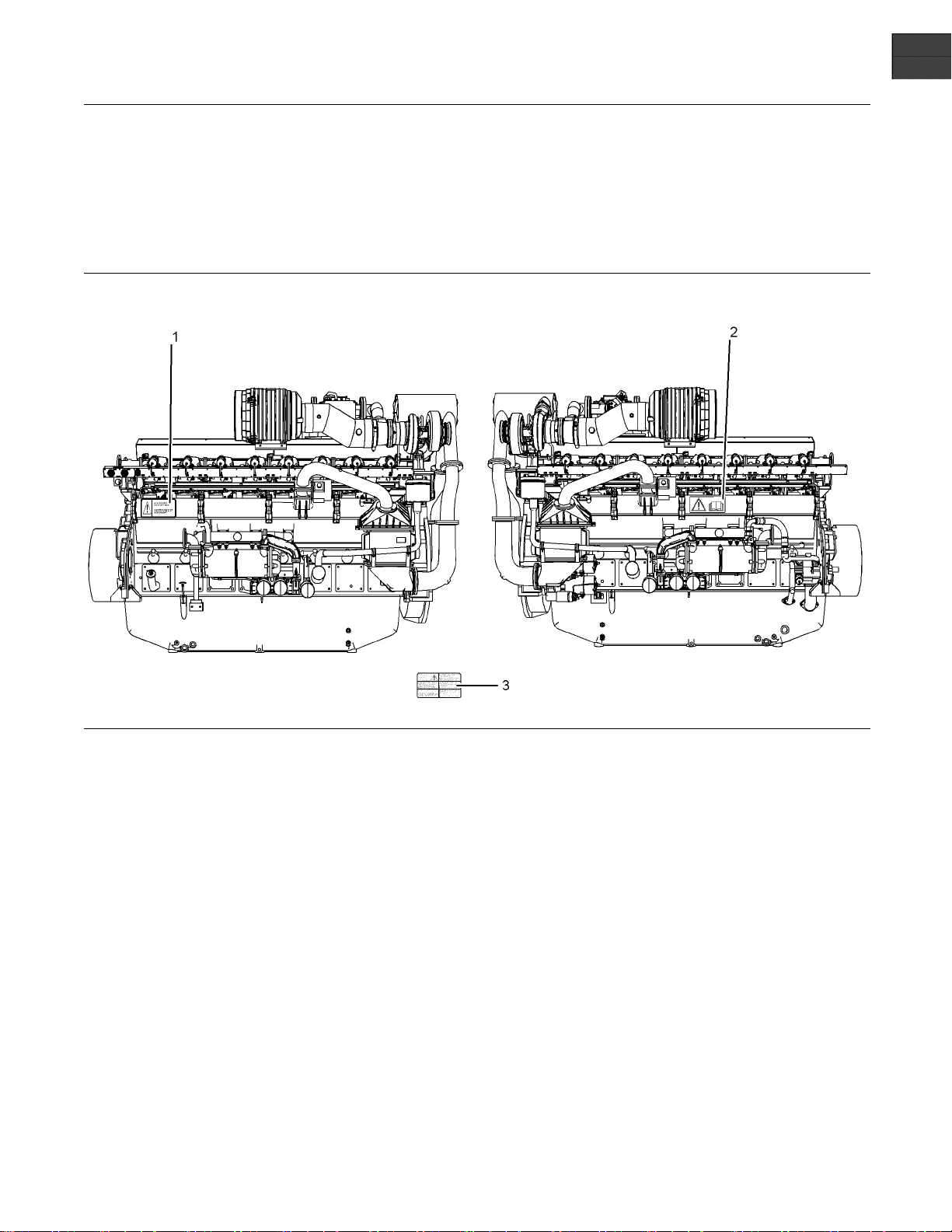
Illustration 1
Typical example
(1) Engine Oil Level (2) Universal warning (3) E ngine Derate
There may be several specific warning signs on your
engine. The exact location and a description of the
warning signs are reviewed in this section. Please
become familiar with all warning signs.
Ensure that all of the warning signs are legible. Clean
the warning signs or replace the warning signs if
the words cannot be read or if the illustrations are
not visible. Use a cloth, water, and soap to clean
the warning signs. Do not use solvents, gasoline, or
other harsh chemicals. Solvents, gasoline, or harsh
chemicals could loosen the adhesive that secures the
warning signs. The warning signs that are loosened
could drop off of the engine.
Replace any warning sign that is damaged or
missing.Ifawarningsignisattachedtoapartofthe
engine that is replaced, install a new warning sign on
the replacement part. Your Perkins dealer or your
distributor can provide new warning signs.
The safety messages that may be attached on the
engine are illustrated .
g01530454
Page 6
6 SEBU8430
Safety Section
Safety Messages
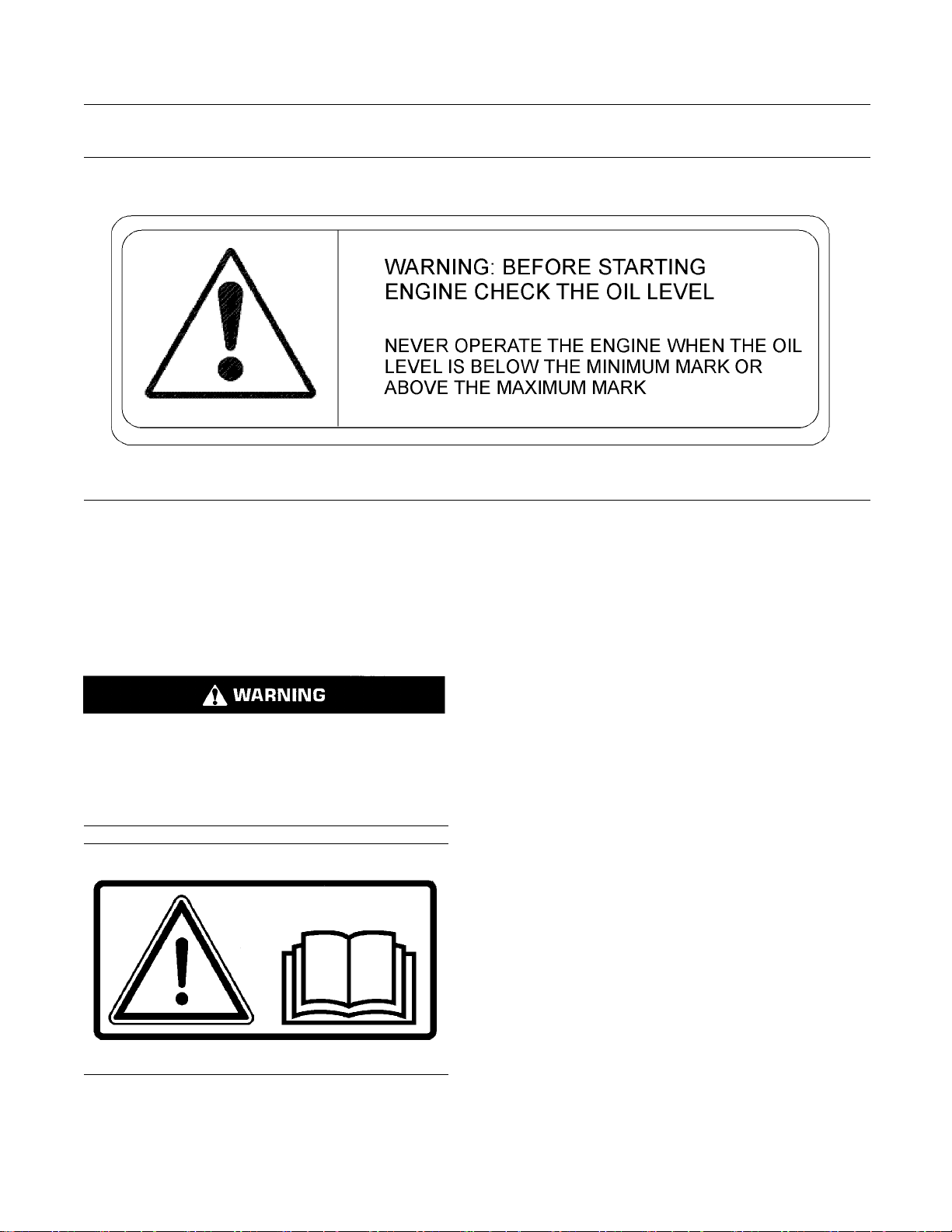
(1) Engine Oil Level
Illustration 2
Typical example
The warning label for checking the engine oil Level
(1) is located on the inlet manifold on the left side of
the engine. Refer to illustration 1.
(2) Universal Warning
Do not operate or work on this equipment unless
you have read and understand the instructions
and warnings in the Operation and Maintenance
Manuals. Failure to follow the instructions or
heed the warnings could result in serious injury
or death.
g01241033
The Universal Warning label (2) is located on the
inlet manifold on the right side of the engine. Refer
to illustration 1.
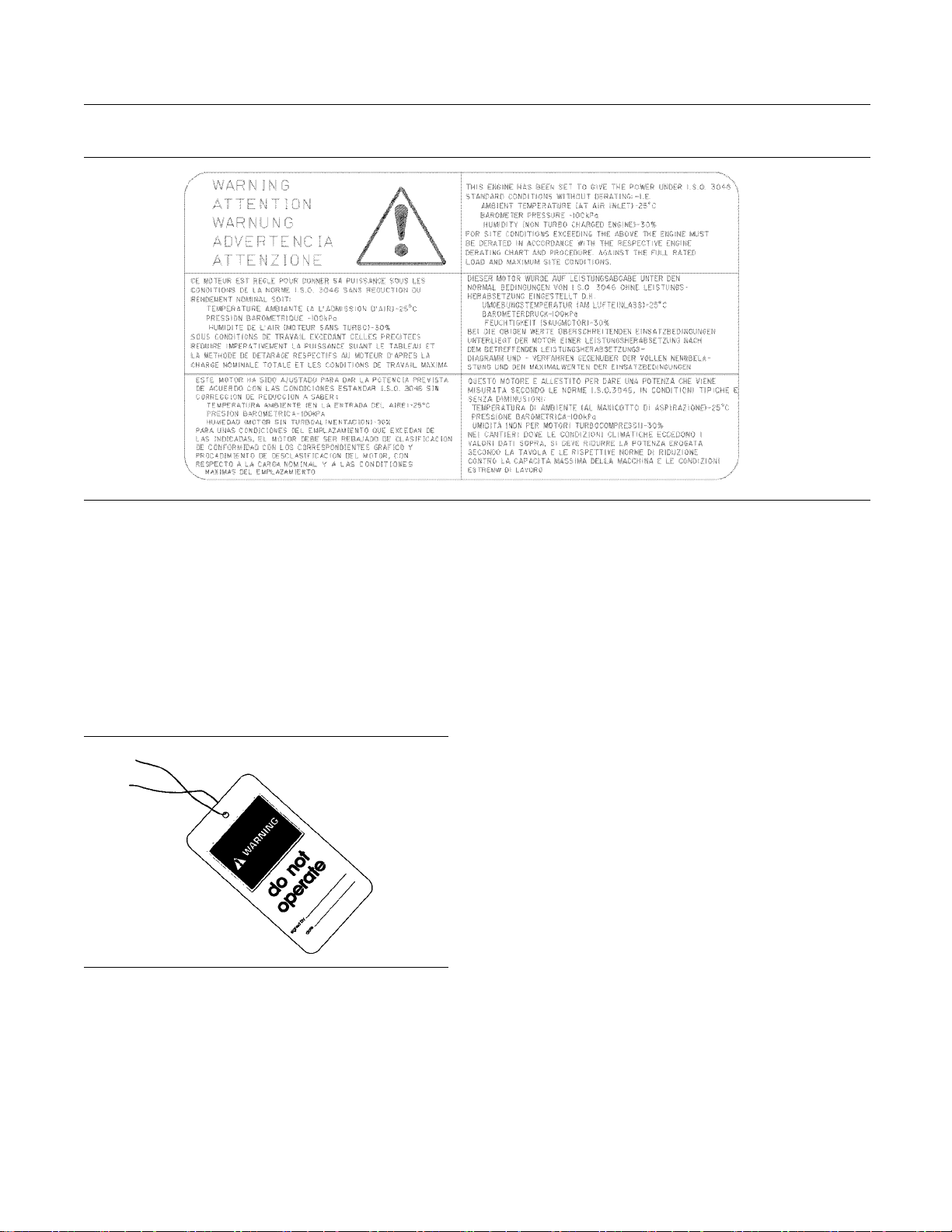
Illustration 3
Typical example
g01234595
Page 7
SEBU8430 7
Safety Section
General Hazard Information
(3) Engine Derate
Illustration 4
Typical example
The warning label for derating engine information
(3) is located on the control box. Refer to OEM
information for the location of the control box.
i03139708
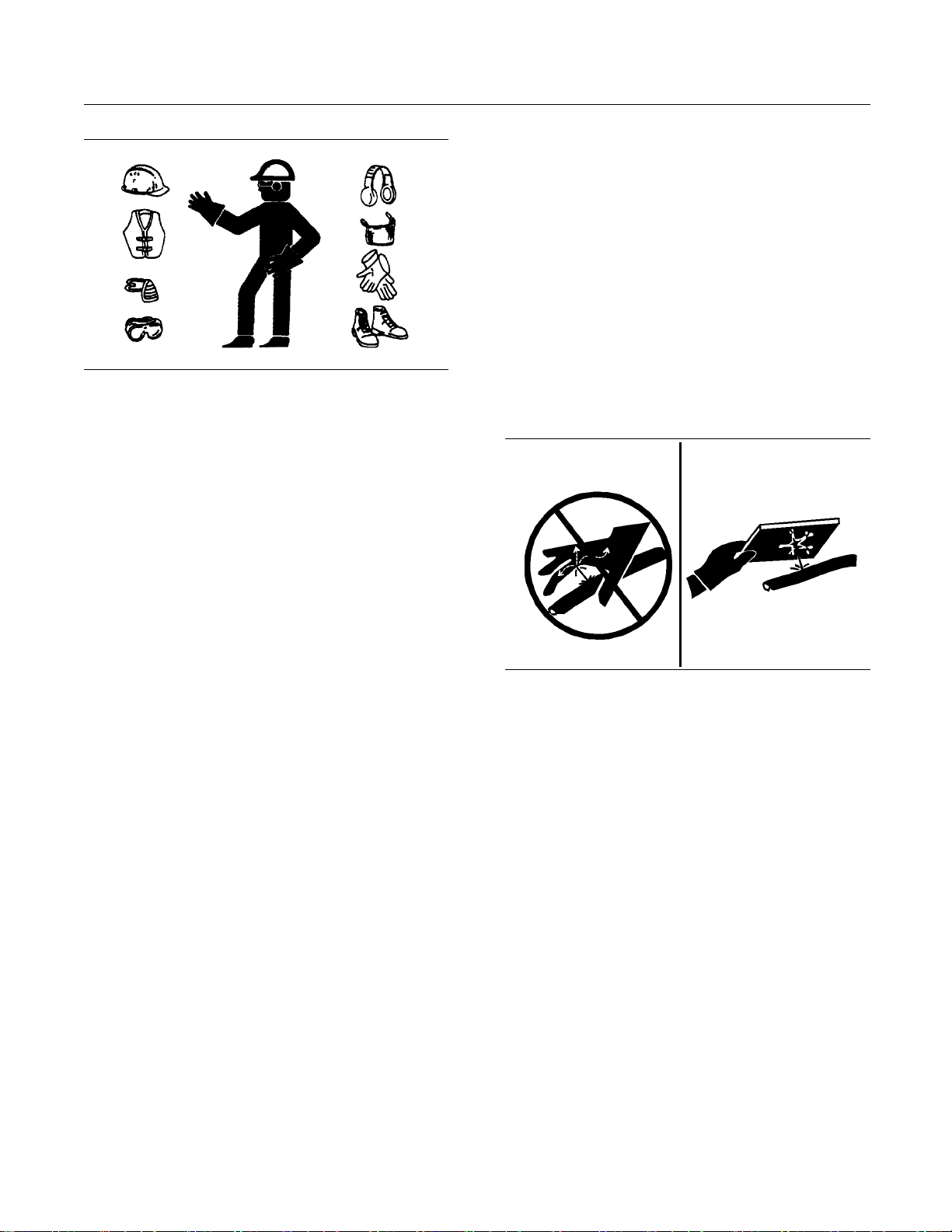
General Hazard Information
Illustration 5
Attach a “Do Not Operate” warning tag or a similar
warning tag to the start switch or to the controls
before the engine is serviced or before the engine
is repaired.
g00104545
g01241021
Engine exhaust contains products of combustion
which may be harmful to your health. Always start the
engine and operate the engine in a well ventilated
area. If the engine is in an enclosed area, vent the
engine exhaust to the outside.
Cautiously remove the following parts. To help
prevent spraying or splashing of pressurized fluids,
hold a rag over the part that is being removed.
Filler caps
•
Grease fittings
•
Pressure taps
•
Breathers
•
Drain plugs
•
Use caution when cover plates are removed.
Gradually loosen, but do not remove the last two
bolts or nuts that are located at opposite ends of
the cover plate or the device. Before removing the
last two bolts or nuts, pry the cover loose in order to
relieve any spring pressure or other pressure.
Do not allow unauthorized personnel on the engine,
or around the engine when the engine is being
serviced.
Page 8
8 SEBU8430
Safety Section
General Hazard Information
Pressurized Air and Water
Illustration 6
Wear a hard hat, protective glasses, and other
•
protective equipment, as required.
When work is performed around an engine that is
•
operating, wear protective devices for ears in order
to help prevent damage to hearing.
Do not wear loose clothing or jewelry that can snag
•
on controls or on other parts of the engine.
Ensure that all protective guards and all covers are
•
securedinplaceontheengine.
g00702020
Pressurized ai
debris and/or hot water to be blown out. This could
result in personal injury.
When pressurized air and/or pressurized water is
used for cleaning, wear protective clothing, protective
shoes, and ey
goggles or a protective face shield.
The maximum a
must be below 205 kPa (30 psi). The maximum
water pressure for cleaning purposes must be below
275 kPa (40 ps
Fluid Penetr
r and pressurized water can cause
eprotection.Eyeprotectionincludes
ir pressure for cleaning purposes
i).
ation
Never put maintenance fluids into glass containers.
•
Glass containers can break.
Use all cleaning solutions with care.
•
Report all necessary repairs.
•
Unless other instructions are provided, perform
the maintenance under the following conditions:
The engine is stopped. Ensure that the engine
•
cannot be started.
Disconnect the batteries when maintenance
•
is performed or when the electrical system is
serviced. Disconnect the battery ground leads.
Tape the leads in order to help prevent sparks.
Do not attempt any repairs that are not understood.
•
Use the proper tools. Replace any equipment that
is damaged or repair the equipment.
If work is carried out on the fuel system obey the
•
local regulations for isolation of the gas supply.
California Proposition 65 Warning
Some constituents of engine exhaust are known to
the State of California to cause cancer, birth defects,
and other reproductive harm.
Illustration 7
Always use a board or cardboard when you check
for a leak. Leaking fluid that is under pressure can
penetrate body tissue. Fluid penetration can cause
serious injury and possible death. A pin hole leak can
cause severe injury. If fluid is injected into your skin,
you must get treatment immediately. Seek treatment
from a doctor that is familiar with this type of injury.
g00687600
Containing Fluid Spillage
Care must be taken in order to ensure that fl uids
are contained during performance of inspection,
maintenance, testing, adjusting and repair of the
engine. Prepare to collect the fluid with suitable
containers before opening any compartment or
disassembling any component that contains fluids.
Tools that are suitable for collecting fluids and
•
equipment that is suitable for collecting fluids
Tools that are suitable for containing fluids and
•
equipment that is suitable for containing fluids
Obey all local regulations for the disposal of liquids.
Page 9
SEBU8430 9
Safety Section
Burn Prevention
Dispose o f Waste Properly
Illustration 8
Improperly disposing of waste can threaten the
environment. Potentially harmful fluids should be
disposed o
Always use leakproof containers when you drain
fluids. Do n
drain, or into any source of water.
f according to local regulations.
ot pour waste onto the ground, down a
g00706404
i03116980
Burn Prevention
Oils
Hot oil and hot lubricating components can cause
personal injury . Do not allow hot oil or hot components
to contact the skin.
If the application has a makeup tank, remove the cap
for the makeup tank after the engine has stopped.
The filler cap must be cool to the touch.
Batteries
The liquid in a battery is an electrolyte. Electrolyte is
an acid that can cause personal injury. Do not allow
electrolytetocontacttheskinortheeyes.
Do not smoke while checking the battery electrolyte
levels. Batteries give off flammable fumes which can
explode.
Always wear protective glasses when you work with
batteries. Wash hands after touching batteries. The
use of gloves is recommended.
i02415237
Fire Prevention and Explosion
Preventio
n
Do not touch any part of an operating engine.
Allow the engine to cool before any maintenance
is performed on the engine. Relieve all pressure in
the appropriate system before any lines, fittings or
related items are disconnected.
Coolant
When the engine is at operating temperature, the
engine coolant is hot. The coolant is also under
pressure. The radiator, the heat exchanger, the
heater and lines contain hot coolant. Any contact with
hot coolant or with steam can cause severe burns.
Allow cooling system components to cool before the
cooling system is drained.
Check the coolant level after the engine has stopped
and the engine has been allowed to cool. Ensure
that the filler cap is cool before removing the filler
cap. The filler cap must be cool enough to touch with
a bare hand. Remove the filler cap slowly in order
to relieve pressure.
Cooling system conditioner is an alkali. Alkali can
cause personal injury. Do not allow alkali to contact
the skin, the eyes, or the mouth.
Illustration 9
All fuels, most lubricants, and some coolant mixtures
are flammable.
Flammable fluids that are leaking or spilled onto hot
surfaces or onto electrical components can cause
a fire. Fire may cause personal injury and property
damage.
A flash fire may result if the covers for the engine
crankcase are removed within fifteen minutes after
an emergency shutdown.
g00704000
Page 10
10 SEBU8430
Safety Section
Fire Prevention and Explosion Prevention
Determine whet
environment that allows combustible gases to be
drawn into the air inlet system. These gases could
cause the engi
property damage, or engine damage could result.
If the applic
gases, consult your Perkins dealer for additional
information about suitable protection devices. All
local regula
Remove all flammable materials such as fuel, oil, and
debris from t
materials to accumulate on the engine.
Store fuels a
containers away from unauthorized persons. Store
oily rags and any flammable materials in protective
containers
storing flammable materials.
Do not expo
Exhaust shields (if equipped) protect hot exhaust
component
a hose, or a seal failure. Exhaust shields must be
installed correctly.
Do not weld on lines or tanks that contain flammable
fluids. Do not flame cut lines that contain flammable
fluid. Clea
nonflammable solvent prior to welding or flame
cutting.
Wiring must be kept in good condition. All electrical
wires must be properly routed and securely attached.
Check all
that are loose or frayed before you operate the
engine. Clean all electrical connections and tighten
all elec
Eliminate all wiring that is unattached or unnecessary.
Do not us
the recommended gauge. Do not bypass any fuses
and/or circuit breakers.
Arcing or sparking could cause a fire. Secure
connections, recommended wiring, and properly
maintai
or sparking.
Inspec
deterioration. The hoses must be properly routed.
The lines and hoses must have adequate support
and sec
recommended torque. Leaks can cause fires.
Oil filt
The filter housings must be tightened to the proper
torque.
trical connections.
ned battery cables will help to prevent arcing
t all lines and hoses for wear or for
ure clamps. Tighten all connections to the
ers and fuel filters must be properly installed.
her the engine will be operated in an
ne to overspeed. Personal injury,
ation involves the presence of combustible
tions must be observed.
he engine. Do not allow any flammable
nd lubricants in properly marked
. Do not smoke in areas that are used for
setheenginetoanyflame.
s from oil or fuel spray in case of a line,
n any such lines thoroughly with a
electrical wires daily. Repair any wires
e any wires or cables that are smaller than
Illustration 10
Gases from a battery can explode. Keep any open
flames or sparks away from the top of a battery. Do
not smoke in battery charging areas.
Never check the battery charge by placing a metal
object across the terminal posts. Use a voltmeter or
ahydrometer.
Improper jumper cable connections can cause
an explosion that can result in injury. Refer to
the Operation Section of this manual for specific
instructions.
Do not charge a frozen battery. This may cause an
explosion.
The batteries must be kept clean. The covers
(if equipped) must be kept on the cells. Use the
recommended cables, connections, and battery box
covers when the engine is operated.
g00704135
Fire Extinguisher
Make sure that a fire extinguisher is available. Be
familiar with the operation of the fire extinguisher.
Inspect the fire extinguisher and service the fire
extinguisher regularly. Obey the recommendations
on the instruction plate.
Lines, Tubes and Hoses
Donotbendhighpressurelines.Donotstrikehigh
pressure lines. Do not install any lines that are bent
or damaged.
Page 11

SEBU8430 11
Safety Section
Crushing Prevention and Cutting Prevention
Repair any line
can cause fires. Consult your Perkins dealer for
repair or for replacement parts.
Check lines, tubes and hoses carefully. Do not use
your bare hand to check for leaks. Use a board or
cardboard to
to the recommended torque.
Replace the p
are present:
End fittings a
•
Outer coverings are chafed or cut.
•
Wires are exposed.
•
Outer coveri
•
Flexible part of the hoses are kinked.
•
Outer covers have embedded armoring.
•
End fittings a
•
Make sure that all clamps, guards, and heat shields
are installe
will help to prevent vibration, rubbing against other
parts, and excessive heat.
s that are loose or damaged. Leaks
check for leaks. Tighten all connections
arts if any of the following conditions
re damaged or leaking.
ngs are ballooning.
re displaced.
d correctly. During engine operation, this
i02143194
i02453744
Mounting and Dismounting
The steps or han
engine. Refer to the OEM for information before any
maintenance or repair is performed.
Inspect the steps, the handholds, and the work area
before mounting the engine. Keep these items clean
and keep these
Mount the engine and dismount the engine only at
locations th
climb on the engine, and do not jump off the engine.
Face the engi
dismount the engine. Maintain a three-point contact
with the steps and handholds. Use two feet and one
hand or use o
controls as handholds.
Do not stand
your weight. Use an adequate ladder or use a work
platform. Secure the climbing equipment so that the
equipment w
Do not carry tools or supplies when you mount the
engine or w
line to raise and lower tools or supplies.
dholds may not be installed on the
items in good repair.
at have steps and/or handholds. Do not
ne in order to mount the engine or
ne foot and two hands. Do not use any
on components which cannot support
ill not move.
hen you dismount the engine. Use a hand
Crushing Prevention and
Cutting Prevention
Support th
the component is performed.
Unless oth
never attempt adjustments while the engine is
running.
Stay clear of all rotating parts and of all moving
parts. Leave the guards in place until maintenance
is perfor
reinstall the guards.
Keep obje
blades will throw objects or cut objects.
When obje
order to avoid injury to the eyes.
Chips or o
are struck. Before objects are struck, ensure that no
one will be injured by flying debris.
e component correctly when work beneath
er maintenance instructions are provided,
med. After the maintenance is performed,
cts away from moving fan blades. The fan
cts are struck, wear protective glasses in
ther debris may fly off objects when objects
i02415253
Ignition
Ignition systems can cause electrical shocks. Avoid
contacting the ignition system components and
wiring.
Systems
i02453806
Before Starting Engine
Inspect the engine for potential hazards.
Before starting the engine, ensure that no one is on,
underneath, or close to the engine. Ensure that the
area is free of personnel.
Ensure that the engine is equipped with a lighting
system that is suitable for the conditions. Ensure that
all lights work properly.
Page 12

12 SEBU8430
Safety Section
Engine Starting
All protective
be installed if the engine must be started in order
to perform service procedures. To help prevent an
accident that
around the parts carefully.
Do not bypass
disable the automatic shutoff circuits. The circuits are
provided in order to help prevent personal injury. The
circuits are
engine damage.
The initial s
has been serviced make provision to shut the engine
off, in order to stop an overspeed. This may be
accomplish
engine, or shutting off the ignition system.
Engine Star
If a warning tag is attached to the engine start switch
or to the controls, DO NOT start the engine or move
the contro
the warning tag before the engine is started.
guards and all protective covers must
is caused by parts in rotation, work
the automatic shutoff circuits. Do not
also provided in order to help prevent
tart-up of a new engine or a engine that
ed by shutting off the fuel supply to the
i03101447
ting
ls. Consult with the person that attached
i00659907
Engine Stopping
To avoid overhe
wear of the engine components, stop the engine
according to the instructions in this Operation and
Maintenance M
(Operation Section).
Use the Emerge
in an emergency situation. Do not use the Emergency
Stop Button for normal engine stopping. After an
emergency st
problem that caused the emergency stop has been
corrected.
On the initial start-up of a new engine or an engine
that has been serviced, make provisions to stop
the engine i
accomplished by shutting off the fuel supply to the
engine, or shutting off the ignition system.
ating of the engine and accelerated
anual, “Engine Stopping” topic
ncy Stop Button (if equipped) ONLY
op, DO NOT start the engine until the
f an overspeed occurs. This may be
i02436641
Electrical S ys tem
All protec
be installed if the engine must be started in order
to perform service procedures. To help prevent an
accident
around the parts carefully.
If there i
the exhaust system, refer to the purge procedure in
this Operation and Maintenance Manual, “Engine
Starting
Always start the engine according to the procedure
that is de
Manual, “Engine Starting” topic in the Operation
Section. Knowing the correct procedure will help to
prevent
Knowing the procedure will also help to prevent
personal injury.
To ensure that the jacket water heater (if equipped) is
working properly, check the water temperature and
the oil
Engine exhaust contains products of combustion
which c
engine and operate the engine in a well ventilated
area. If the engine is started in an enclosed area,
vent th
tive guards and all protective covers must
that is caused by parts in rotation, work
s a possibility that unburned gas remains in
” topic in the Operation Section.
scribed in the Operation and Maintenance
major damage to the engine components.
temperature during heater operation.
an be harmful to your health. Always start the
e engine exhaust to the outside.
Never disconnect any charging unit circuit or battery
circuit cable from the battery when the charging unit
is operating. A spark can cause the combustible
gases that are produced by some batteries to ignite.
To help prevent sparks from igniting combustible
gases that are produced by some batteries, the
negative “−” cable should be connected last from the
external power source to the negative “−” terminal
of the starting motor. If the starting motor is not
equipped with a negative “−” terminal, connect the
cabletotheengineblock.
Check the electrical wires daily for wires that
are loose or frayed. Tighten all loose electrical
connections before the engine is started. Repair all
frayed electrical wires before the engine is started.
See the Operation and Maintenance Manual for
specific starting instructions.
Grounding Practices
Note: All ground lines must return to the battery
ground.
Page 13
SEBU8430 13
Safety Section
Electrical System
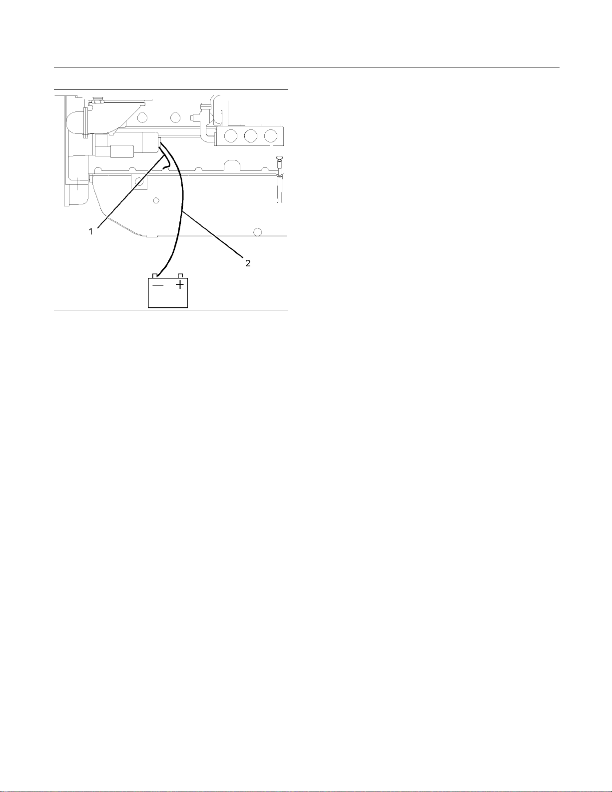
Illustration 11
Typical example
(1) Starting motor to ground
(2) Battery negative to engine
g01217202
Correct grounding for the engine electrical system
is necessary for optimum engine performance
and reliability. Incorrect grounding will result in
uncontrolled electrical circuit paths and in unreliable
electrical circuit paths.
Uncontrolled electrical circuit paths can result in
damage to the crankshaft bearing journal surfaces
and to aluminum components.
The connections for the grounds should be tight and
free of corrosion. The engine alternator must be
grounded to the negative “-” battery terminal with
a wire that is adequate to handle the full charging
current of the alternator.
The power supply connections and the ground
connections for the engine electronics should always
be from the isolator to the battery.
Page 14
14 SEBU8430
Product Information Section
Model Views and Specifications
Product Information
Section
Model Views and
Specifications
i02885828
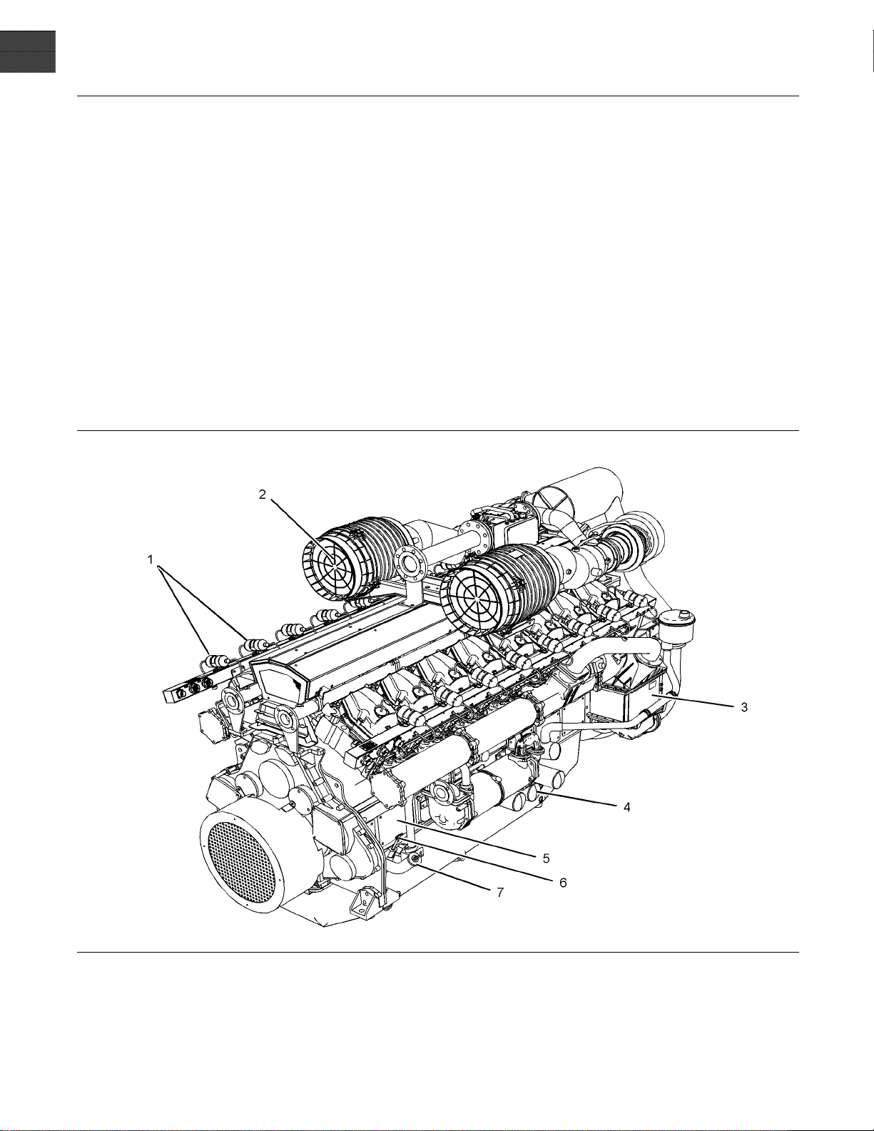
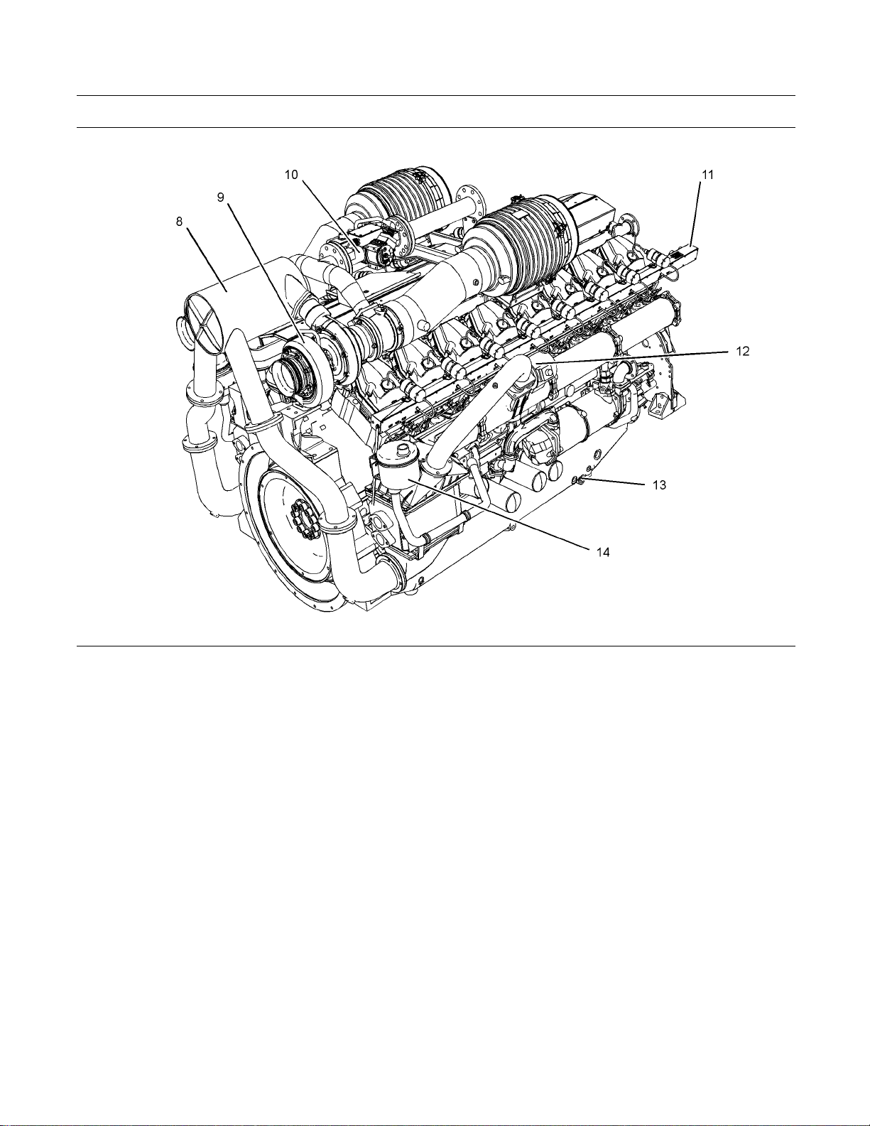
Model View Illustrations
The illustrations show various typical features of
4016 Series TRS Engine. The illustrations do not
show all of the options that are available.
Illustration 12
Typical example
(1) Ignition coils
(2) Air filter
(3) Charge air cooler
(4) E ngine oil filters
(5) The inspection cover for the Crankcase
(6) Oil level gauge (dipstick)
g01525185
(7) Oil filler cap
Page 15
SEBU8430 15
Product Information Section
Model Views and Specifications
Illustration 13
Typical example
(8) Tumbulator
(9) Turbocharger
(10) Gas control valve
(11) Rail for the engine wiring
(12) Throttle
(13) O il drain plug
i02885810
Product Description
The Perkins Engines were developed in order to
provide gas engines for generator set applications.
The engines have the ability to burn a wide variety of
gaseous fuels.
Fuel System
The fuel is delivered to the gas control valve. The gas
must be at a constant pressure and the gas pressure
must be stable. The pressure must be within a range
of5to25kPa(0.72to3.6psi).Higherpressurewill
need to be reduced with an additional gas regulator.
g01525189
(14) Ope n breather system
Theventuriislocatedinthegasmixerbody
immediately before the turbocharger. As air is
accelerated through the venturi gas is mixed with the
air. This mixture is compressed by the turbocharger.
The mixture passes through the tumbulator, and the
charge coolers, and into the inlet manifolds. The
speed and the load is governed by electronically
controlled throttle valves.
A digitally controlled gas valve maintains the air/fuel
ratio. This system is adjustable. Refer to Systems
Operation, Testing and Adjusting for details. This is
the only means of adjusting the exhaust emissions.
Ignition System
The engine is equipped with an Electronic Ignition
System (EIS). The EIS provides dependable firing
and low maintenance. The EIS provides precise
control of the following factors:
Page 16
16 SEBU8430
Product Information Section
Model Views and Specifications
Voltage
•
Duration of the spark
•
Ignition timing
•
Level of energ
•
All 4016TRS gas engines are equipped with a device
to detect deto
the ignition system. This device automatically retards
the ignition timing.
The ignition timing is retarded when excessive
detonation is sensed. If detonation continues after full
retardation
Lubrication
The engine lubrication oil is supplied by a pump
that is drive
oil is filtered. A bypass valve provides unrestricted
flow of lubrication oil to the engine parts if the oil
filter eleme
will open if the oil filter differential pressure reaches
34.4to48.2kPa(5to7psi).Theengineoilpressure
operates in
Note: The engine lubrication oil is not fi ltered when
the bypass v
to operate when the bypass valve is open. This can
damage the engine components.
y of the ignition
nation which is connected directly into
, then the engine must be shut down.
System
n by a gear. The oil is cooled and the
nts become plugged. The bypass valve
a range of 415 to 450 kPa (60 to 65 psi).
alve is open. Do not allow the engine
Cooling System
The system is us
important factor.
ed when recovery of heat is not an
Cogeneration engine
Cogeneration
otherwisebewasted.
The following
Water pumps
•
Water temperature regulator ( thermostat)
•
All water tube
•
This system is the responsibility of the OEM.
uses energy from heat which would
items are not supplied:
assemblies
Engine Service Life
Engine efficiency and maximum utilization of engine
performance depend on adherence to proper
operation an
includes the use of recommended lubricants, fuels,
and coolants.
For the engine maintenance that is required,
refer to the Operation and Maintenance Manual,
“Maintenan
Section.
d maintenance recommendations. This
ce Interval Schedule” in the Maintenance
i02885756
Specifications
The water enters the engine from the oil cooler and
the water is passed through the cylinder block. The
water exi
exits the engine from the water outlet.
ts the cylinder head into the rail. The water
Electrounit
This type
components:
Jacket wa
•
Water temperature regulator (thermostat)
•
Coolant pipe for the charge cooler
•
A water pu
•
A water temperature regulator (thermostat) that
•
controls
cooler
Battery c
•
of engine is supplied with the following
ter coolant pump
mp for the charge cooler
the water inlet temperature for the charge
harging alternator
General Eng
Illustration 14
Sixteen cylinder
(X) Inlet valves
(Y) Exhaust valves
ine Specifications
g01210841
Page 17

SEBU8430 17
Product Information Section
Model Views and Specifications
Table 1
4016 Engine Specifications
Rated rpm 1500
Number of Cylinders
Configuration Vee-form
Bore
160 mm (6.299 inch)
Stroke 190 mm (7.480 inch)
Displacement
61.123 L (3729.954 in
Compression ratio
Aspiration Turbocharged
Rotation (flyw
heel end)
Counterclock
Inlet valve lash (cold) 0.40 mm (0.016 inch)
Exhaust valve lash (cold) 0.40 mm (0.016 inch)
Firing order 1A-1B-3A-3B-7A-7B-
5A-5B-8A-8B-6A-6B-
16
13:1
wise
2A-2B-4A-4B
3
)
Page 18
18 SEBU8430
Product Information Section
Product Identification Information
Product Identification
Information
i02978102
Plate Locations and Film
Locations
Engine Identification
Perkins engines are identified by an engine serial
number.
A typical example of an engine serial number is
DIH R**** U10001S.
D
_________________________________________ Made in Stafford
______________________________________Application (Table 2)
I
_______________________________ Type of engine (Table 3)
H
Table 4
Number of Cylinders
F 6
H 8
M 12
R 16
Perkins dealers and Perkins distributors require all of
these numbers in order to determine the components
that were included in the engine. This permits
accurate identification of replacement part numbers.
Serial Nu mber Plate
_________________________ Number of cylinders (Table 4)
R
_________________________________ _ Fixed build number
*****
____________________________Built in the United Kingdom
U
00001
S
Table 2
Table 3
____________________________________Engine Number
_____________________________________ Year of Manufacture
Application
G Genset
I
F
E
G 4016-E61-TRS
H TRS Combined Heat and Power Unit
J TRS Gas Unit
Gas
Type of engine (Gas)
TESI Gas unit
TESI Combined Heat and Power unit
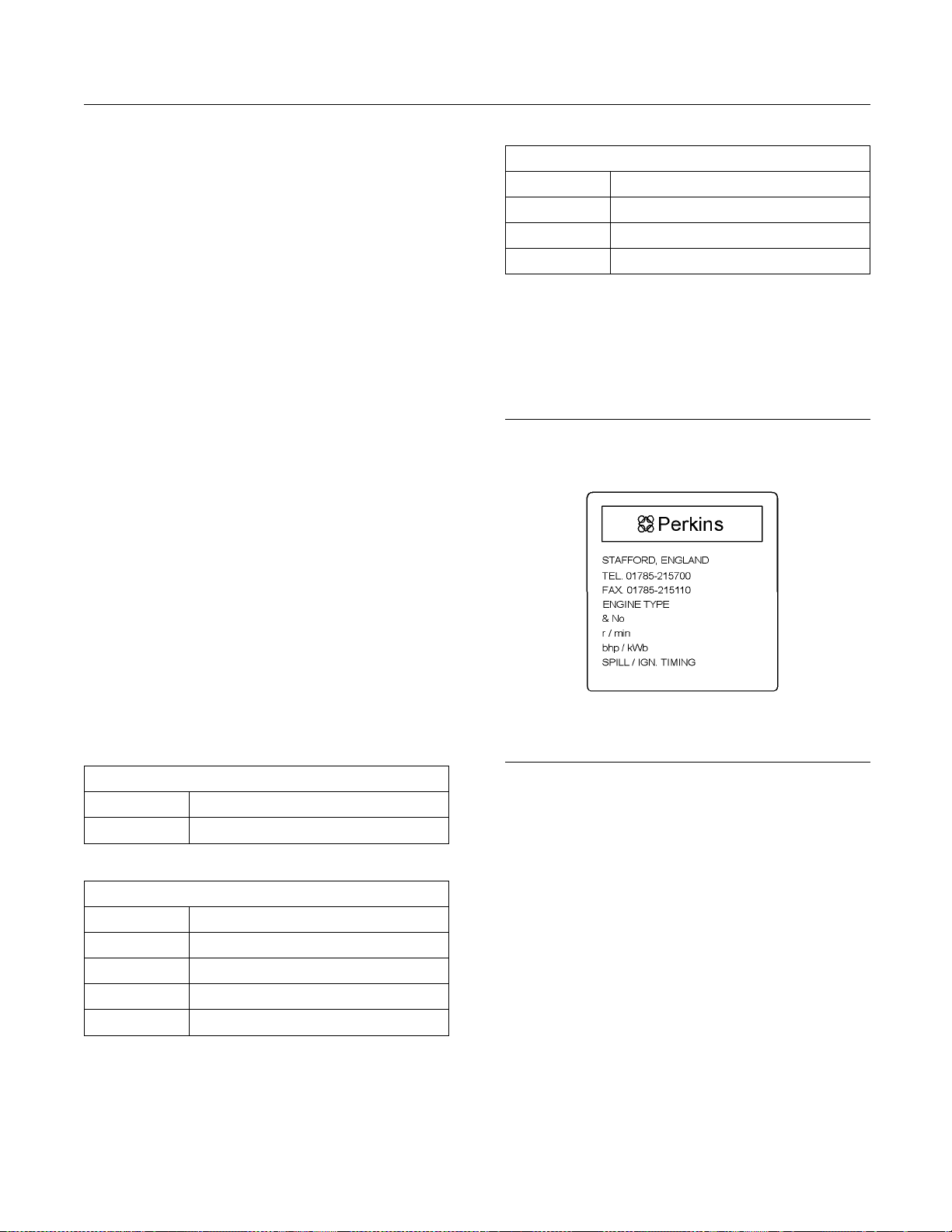
Illustration 15
Serial number plate
The engine serial number plate contains the following
information:
Place of manufacture
•
Telephone number of manufacturer
•
Fax number of manufacturer
•
Type of engine
•
Engine serial number
•
g01266904
Rated speed
•
Power output
•
Engine timing
•
Rating
•
Page 19
SEBU8430 19
Product Information Section
Product Identification Information
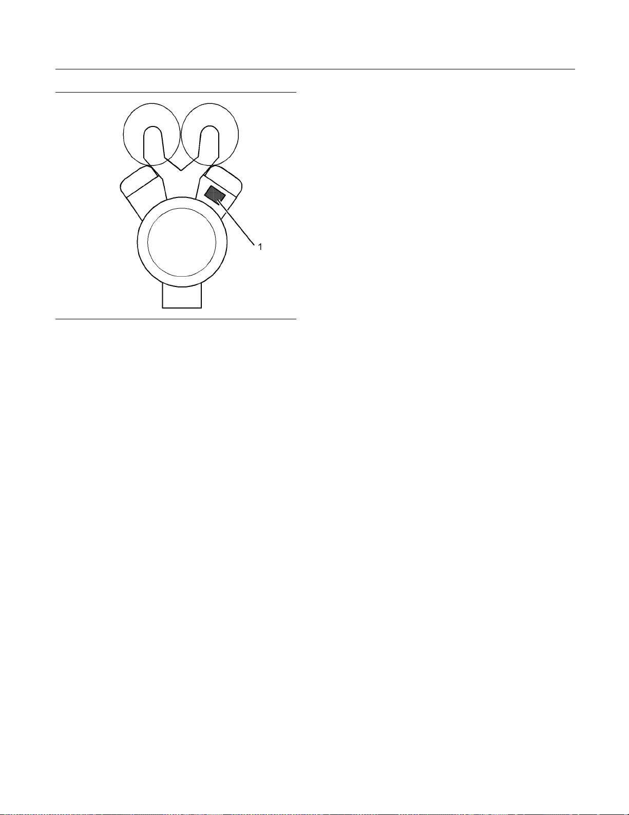
Illustration 16
The location of the serial number plate for vee-form engines
g01229580
The serial number plate (1) on a vee-form engine is
located on the rear face of the cylinder block (bank
A). See Illustration 16.
Page 20
20 SEBU8430
Operation Section
Lifting and Storage
Operation Section
Lifting and Storage
i02885807
Product Lifting
NOTICE
Never bend the eyebolts and the brackets. Only load
the eyebolts and the brackets under tension. Remember that the capacity of an eyebolt is less as the angle
between the supporting members and the object becomes less than 90 degrees.
When it is necessary to remove a component at an
angle, only use a link bracket that is properly rated for
the weight.
To re m ov e t he e n
that are on the engine. If necessary, remove engine
components in order to avoid damage from the lifting
device.
Lifting eyes are designed and installed for specific
engine arran
and/or the engine make the lifting eyes and the lifting
fixtures obsolete. If alterations are made, ensure
that correct
your Perkins dealer or your Perkins distributor for
information regarding fixtures for correct engine
lifting.
gine ONLY, use the lifting eyes
gements. Alterations to the lifting eyes
lifting devices are provided. Consult
i03139740
Product S t orag e
Refer to Perkins Engine Company limited, Stafford
for information on engine storage.
There are three different levels of engine storage.
Level “A, B and C”.
ration 17
Illust
Typical example
Level “A ”
Level “A” will give protection for 12 month for diesel
engines and 12 month protection for gas engines.
This is for engines that are transported by a container
or a truck. Level “A” is for the transportation of items
that are within the United kingdom and within Europe.
Level “B ”
This level is additional to level “A”. Level “B ” will
give protection under normal storage condition
from −15° to +55°C (5° to 99°F) and “90%”
relative humidity for two years. Level “B” is for the
transportation of items overseas.
Level “C ”
In order to protect the product to Level “C”, contact
Perkins Engines Company Limited Stafford.
g01230422
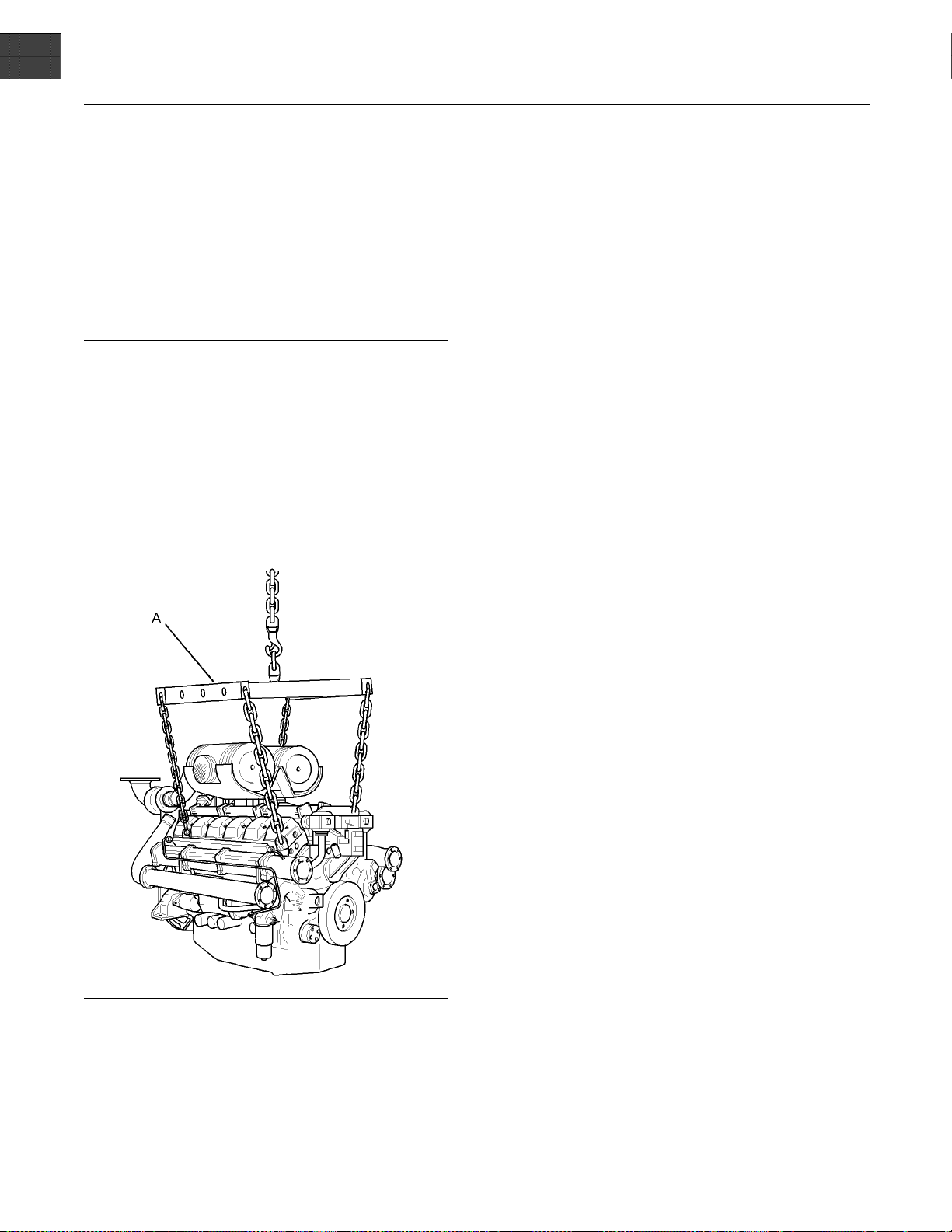
Use a hoist to remove heavy components. Use a
lifting beam (A) to lift the engine. All supporting
member
to each other. The chains and cables should be
perpendicular to the top of the object that is being
lifted
s (chains and cables) should be parallel
.
Page 21

SEBU8430 21
Operation Section
Gauges and Indicators
Gauges and Indicators
i02917145
Gauges and Indicators
Gauges are su
information about the gauge package, see the OEM
information.
Gauges provide indications of engine performance.
Ensure that the gauges are in good working order.
Determine th
the gauges over a period of time.
Noticeable c
potential gauge or engine problems. Problems may
also be indicated by gauge readings that change
even if the r
Determine and correct the cause of any significant
change in the readings. Consult your Perkins dealer
or your Per
If no oil pressure is indicated, STOP the engine. If
maximum co
the engine. Engine damage can result.
pplied by the OEM. For more
e normal operating range by observing
hanges in gauge readings indicate
eadings are within specifications.
kins distributor for assistance.
NOTICE
olant temperature is exceeded, STOP
Engine Oil
the engine oil pressure is 415 to 450 kPa
(60to65psi).
Pressure – The range for
Jacket Wat
Typical water temperature into the engine
is 71°C (160°F). Higher temperatures
may occur
temperature reading may vary according to load. The
reading should never exceed 96°C (204°F).
1. Ahighwat
cooling system.
2. Alowoilp
gallery of the engine.
3. Ahighpre
inlet manifold of the engine.
under certain conditions. The water
er temperature switch is installed in the
ressure switch is installed in the oil
ssure Backfire switch is installed to the
er Coolant Temperature –
Page 22

22 SEBU8430
Operation Section
Features and Controls
Features and Controls
i02885816
Performance Param eters
Air/Fuel Ratio
The correct air/fuel ratio is very important for the
following considerations:
Margin of detonation
•
Control of emissions
•
Engine performance
•
Achieving optimum service life for the engine
•
Compliance with legal requirements
•
If the air/fuel ratio is not appropriate for the fuel and
the operating conditions, a failure of the engine may
occur. The service life of the turbochargers, the
valves, and other components may be reduced.
Fuel Supply Pressure and Temperature
The gas supply to the control valve for the air/fuel
ratiomustbebetween5to25kPa(0.72to3.6psi).
If a higher pressure is required a separate gas
regulator must be installed into the fuel line.
The temperature of the gas into the air/fuel ratio
controlsystemmustbebetween5to40°C
(41 to 104°F).
Note: No zero pressure regulator is required with
the air/fuel ratio control system for the 4016-61TRS
engine.
Air, Charge Cooler Water
Temperatur e and Altitude
i02894958
Sensors and Electrical
Components
Electronic Ignition System (EIS)
The Electronic Ignition System includes the following
components:
The control module for the ignition
•
Timing sensor
•
Ignition coil on each cylinder
•
Spark plugs
•
Ignition har
•
The ignition system generates high voltage. Do
not come in contact with the ignition system with
the engine in
personal injury or death.
The EIS contr
serviceable parts. The timing sensor uses the
magnets that are mounted on the camshaft in order
to generate
cylinder plus an index magnet in order to indicate the
start of each cycle. The EIS control module has a
output to e
each cylinder, the EIS sends a pulse to the primary
winding of the ignition coil. The coil increases the
voltage on
spark across the spark plug electrode.
The electr
following activities:
Ignition t
•
ness
ol module is a sealed unit with no
thetimingpulses.Onepulseforeach
ach ignition coil. To initiate combustion in
the secondary winding which creates a
onic ignition system provides control for the
iming
operation. This voltage can cause
Refer to technical date sheet for the charts for
thederateinordertodeterminethemaximum
temperatures into the engine and the altitude derate.
Ignition energy
•
Protection from detonation
•
Switches
The engin
High cooling water temperature switch
•
Low oil pressure switch
•
High press
•
e is installed with the following switches.
ureswitchforthemanifold
Page 23

SEBU8430 23
Operation Section
Features and Controls
Governor
The engine is installed with a digital governor that
includes the following components:
Digital governor
•
Actuators and throttle valves
•
Magnetic pickup
•
Wiring harness
•
The governor uses the magnetic pickup to sense
engine speed from the flywheel gear teeth. This
signal is fed into the governor, which drives an
actuator. This is connected to the throttle valves in
order t o control the amount of combustion gas/air.
A DC Desk service tool with the appropriate software
key and cable are required in order to perform any
adjustments to the system.
Detonation System
The equipment for the detonation system senses
detonation or knock which may be caused by
poor gas or may be caused by high combustion
temperatures.
The detonation system includes the following
components:
Detonation sensor on each cylinder
•
Control module for detonation
•
Wiring harness
•
The detonation system operates by measuring
vibrations on the crankcase. The signal is processed
in order to eliminate normal engine vibrations. If
detonation above a predetermined level is detected
the ignition timing is retarded. If detonation ceases,
theignitiontimingthatisretardedwillbegradually
brought back to a normal value. If the engine
continues detonation the detonation system will
operate in order to stop the engine.
i02427728
Alarms a
nd Shutoffs
Engines may be e
protective devices that are not included in this section.
This section contains some general information about
thefunctiono
Alarms and shutoffs are electronically controlled.
The operatio
components which are actuated by a sensing unit.
The alarms and shutoffs are set at critical operating
temperature
protect the engine from damage.
The alarms fu
when an abnormal operating condition occurs. The
shutoffs function in order to shut down the engine
whenamorec
occurs. The shutoffs help to prevent damage to the
engine.
Shutoffs may cause unburned gas to remain in the
air inlet and in the exhaust manifold.
Unburned gas in the air i n let and exhaust system
may ignite
injury and/or property damage may result.
Before sta
burned gas, purge the unburned gas from the air
inlet and exhaust system. Refer to the topic on
purging u
section.
If an engi
always determine the cause of the shutoff. Make
the necessary repairs before attempting to start the
engine.
Become familiar with the following information:
Types of the alarm and shutoff controls
•
Location
•
Conditions which cause each control to function
•
Resetting procedure that is required before starting
•
the engine
rting an engine that may contain un-
nburned gas in the “Starting the Engine”
ne protective device shuts off the engine,
s of the alarm and shutoff controls
quipped with optional engine
f typical engine protective devices.
n of all alarms and shutoffs utilize
s, pressures, or speeds in order to
nction in order to warn the operator
ritical abnormal operating condition
when the engine is started. Personal
Testing Alarms and Shutoffs
The OEM will supply this system. Refer to the OEM
for more information.
Alarms must function properly in order to provide
timely warning to the operator. Shutoffs help to
prevent
to determine if the engine protective devices are
in good working order during normal operation.
Malfun
engine protective devices.
damage to the engine. It is impossible
ctions must be simulated in order to test the
Page 24

24 SEBU8430
Operation Section
Features and Controls
NOTICE
During testing
simulated.
, abnormal operating conditions must be
The tests must b
vent possible damage to the engine.
Periodic test
proper operation is recommended maintenance. To
prevent damage to the engine, only authorized
service perso
e performed correctly in order to pre-
ingofengineprotectivedevicesfor
nnel should perform the tests.
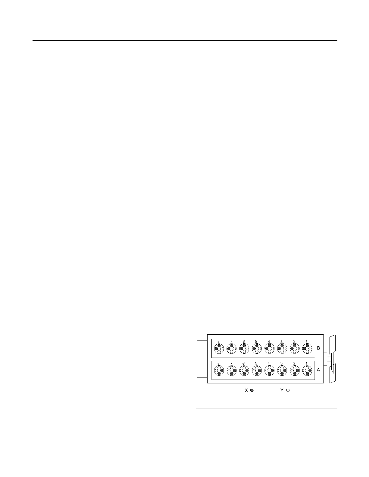
i02918497
Control Panel
All 4016TRS e
mounted control panel. This unit contains the
following components and integrated wiring.
Ignition system
•
Detonation
•
The system for governing engine speed
•
The control panel is connected to the engine via 4
harness assemblies.
ngines are supplied with a remote
system
Illustration 18
g01544873
Page 25

SEBU8430 25
Operation Section
Engine Starting
Engine Starting
i02894959
Before Start ing Engine
Before the en
daily maintenance and any other periodic
maintenance that is due. Refer to the Operation
and Maintena
Schedule” for more information.
For the maxim
•
thorough inspection within the engine compartment
before the engine is started. Look for the following
items: oil l
excessive dirt and/or grease. Remove any excess
dirt and/or grease buildup. Repair any faults that
were ident
Inspect the cooling system hoses for cracks and
•
for loose c
Inspect the alternator and accessory drive belts for
•
cracks, br
gine is started, perform the required
nce Manual, “Maintenance Interval
um service life of the engine, make a
eaks, coolant leaks, loose bolts, and
ified during the inspection.
lamps.
eaks, and other damage.
Observe the air
•
the air cleaner when the diaphragm enters the red
zone, or when the red piston locks in the visible
position.
Remove any electrical loads.
•
cleaner service indicator. Service
i02982579
Cold Weather Starting
A jacket water heater is required for starting when the
temperature is below 10 °C (50 °F). The temperature
of the jacket water should be maintained at 40 °C
(104 °F).
Note: A oil pan immersion heater must not be
installed.
The 4016-61TRS engine is equipped with Multitorch
spark plugs. Under certain circumstances, it is
possible for condensation to develop within the
nozzle for the spark plug. This may cause difficulty in
engine starting. If this occurs, conduct the following
procedure:
Inspect the wiring for loose connections and for
•
worn wires
Open the fuel supply valve (if equipped).
•
Do not start the engine or move any of the controls
•
if there is a “DO NOT OPERATE” warning tag or
similar w
to th e controls.
Ensure th
•
clear.
All of the
•
damaged guards or for missing guards. Repair
any damaged guards. Replace damaged guards
and/or m
Check electrical cables and check the battery for
•
poor con
Reset all of the shutoffs or alarm components (if
•
equippe
Check the engine lubrication oil level. Maintain the
•
oil leve
mark on the engine oil level gauge.
Check th
•
in the header tank (if equipped). Maintain the
coolant level to the “FULL” mark on the header
tank.
or frayed wires.
arning tag attached to the start switch or
at the areas around the rotating parts are
guards must be put in place. Check for
issing guards.
nections and for corrosion.
d).
l between the “Min” mark and the “Max”
e coolant level. Observe the coolant level
1. Remove the spark plugs from four of the engines
cylinders, refer to Disassembly and Assembly,
“Spark Plugs - Remove and Install”
2. Use a suitable tool in order to heat the tip of the
spark plug.
3. Replace the spark plugs, refer to Disassembly and
Assembly, “Spark Plugs - Remove and Install”
4. Start the engine.
Extra battery capacity may be necessary in order to
start the engine.
i02894960
Starting
Engine exhaust contains products of combustion
which ma
and operate the engine in a well ventilated area
and, if in an enclosed area, vent the exhaust to the
outside
the Engine
y be harmful to your health. Always start
.
Page 26

26 SEBU8430
Operation Section
Engine Starting
NOTICE
For initial sta
start-up of an engine that has been serviced, make
provision to shut the engine off should an overspeed
occur. This ma
fuel supply and/or the ignition to the engine.
Unburned gas in the air inlet and exhaust system
may ignite when the engine is started. Personal
injury and/or property damage may result.
Before starting an engine that may contain unburned gas, purge the unburned gas from the air
inlet and exhaust system. Refer to the topic on
purging unburned gas in the “Starting the Engine”
section.
The OEM will supply this system. Refer to the OEM
for more information.
Note: The OEM must ensure that using the
“EMERGENCY STOP” button will shut off both the
fuel and the ignition.
rt-up of a new or rebuilt engine, and for
y be accomplished by shutting off the
5. Stop the engine
engine coolant level.
6. Operate the en
conditions. Check the gauges in order to see the
condition of the engine.
7. If the engine fails to start after two attempts turn
off the gas supply and investigate the cause.
and check the engine oil and the
gine under normal working
Purging Unburned Gas
The following events cause unburned gas to remain
in the air inlet and in the exhaust manifold:
Emergency stop
•
Engine overs
•
Unsuccessful successive attempts to start the
•
engine
Unburned gas may remain in the air inlet and exhaust
system after
the engine. The unburned gas may increase to a
concentration that may ignite during a successive
attempt to s
peed
several unsuccessful attempts to start
tart the engine.
Do not start the engine or move any of the controls
if there is a “DO NOT OPERATE” warning tag or
similar warning tag attached to the start switch or to
the controls.
Ensure that no one will be endangered before the
engine is started and when the engine is started.
Perform the procedures that are described in this
Operation and Maintenance Manual, “Before Starting
Engine” (Operation Section).
Final Checks and First Engine Start
Note: The fuel system must comply with all local
regulations.
The OEM will supply this system. Refer to the OEM
for more information.
1. The starting and the stopping of the engine must
be on no load.
2. The procedure for starting and stopping a radiator
cooled and CHP gas engine will be determined
by the OEM relative to each individual engine
installation.
3. Operate the engine at rated speed for ten minutes.
4. Inspect the engine for leaks in the oil system and
the coolant systems.
Perform the following procedure in order to purge
the unburne
1. Turn the manual gas shutoff valve to the CLOSED
position.
2. Disable the ignition system.
3. Turn the engine control switch to the START
position. Crank the engine for a minimum of six
seconds.
4. Enable the ignition system.
5. Turn the manual gas shutoff valve to the OPEN
position.
6. Start the engine. Refer to the engine starting
procedure and refer to OEM in order to start the
engine.
Engine St
Note: If the engine fails to start after the maximum
cranking
attempting to restart the engine, investigate the
cause. Follow the procedure for purging unburned
gas once t
Note: The starting procedure may differ because of
the OEM sy
1. The signal is received.
d gas:
arting Procedure
time, the engine will be shut down. Before
he cause has been detected.
stem that is installed.
Page 27

SEBU8430 27
Operation Section
Engine Starting
2. Check that the g
pressure is incorrect a warning is activated and
the electrical system will shut down. If the gas
pressure is in
3. Activate the governor.
4. Activate the starting motor.
5. Operate the st
order to purge the system.
6. Activate the
Continue to operate the starting motor.
7. After the eng
motor.
Note: If the e
cranking time, the engine will be shut down.
8. Theengineis
Operation of
as pressure is in limits. If the gas
limits, go to the next step.
arting motor for three seconds in
gas valve and activate the ignition.
ine is started disengage the starting
ngine fails to start after the maximum
now operating.
the Generator Set
Control Panel
i02978143
After Starting Engine
For new install
rebuilt, check and adjust the air/fuel ratio, refer to
Systems Operation Testing and Adjusting, “Air/Fuel
Ratio Control
detect any unusual engine performance through the
load range of the engine.
Check for leaks in the air and in the fluid systems.
ations and engines that are recently
- Adjust”. Monitor the engine in order to
For information on operation for a specific generator
set control panel, refer to the Operation and
Maintenanc
control panel.
e Manual for the generator and the
Automatic Starting
When the engine is in the AUTOMATIC mode, the
engine can
injury, always remain clear of the the engine when
the engine is in the AUTOMATIC mode.
start at any moment. To avoid personal
Manual starting
Refer to the OEM manual for information on the
controls in order to manually start the engine.
i02428473
Starting with Jump Start
Cables
Do not use jump start cables in order to start the
engine. Charge the batteries or replace the batteries.
Refer to Operation and Maintenance Manual,
“Battery - Replace”.
Page 28

28 SEBU8430
Operation Section
Engine Operation
Engine Operation
i02894963
Engine Operation
Proper opera
attaining the maximum service life and economy for
the engine. Follow the instructions in this Operation
and Maintena
Testing and Adjusting in order to minimize operating
costs and maximize the service life of the engine.
Observe the gauges and the instrument panel
frequently during engine operation and record
the data in a
the specifications for normal engine operation.
Comparing the data over time will help to detect
changes in
Investigate any significant change in the readings.
Monitor th
discrepancies are found.
tion and maintenance are key factors in
nce Manual and Systems Operation,
log regularly. Compare the data to
engine performance.
e engine operation and take action when
Partial load and Low Load
Operation
Extended operation below 50% of the base power
load will c
Carbon formation in the cylinder
•
ause the following results:
Detonation
•
Power los
•
Poor performance
•
Accelerated wear of components
•
Increase
•
Glazing of the cylinder bore
•
s
d oil consumption
Page 29

SEBU8430 29
Operation Section
Engine Stopping
Engine Stopping
i02978181
Emergency Stopping
The OEM will s
In the event of an emergency or in the event of an
engine overs
valve and the governor.
Emergency sh
ONLY. DO NOT use emergency shutoff devices or
controls for normal stopping procedure.
Pressing the Emergency Stop Button may cause
unburned gas to remain in the air inlet and in the
exhaust man
Unburned ga
may ignite when the engine is started. Personal
injury and/or property damage may result.
Before starting an engine that may contain unburned gas, purge the unburned gas from the air
inlet and e
purging unburned gas in the “Starting the Engine”
section.
upply the system.
peed, switch off the ignition, the gas
NOTICE
utoff controls are for EMERGENCY use
ifold.
s in the air inlet and exhaust system
xhaust system. Refer to the topic on
i02453745
Manual Stop Procedure
In order to manu
OEM for information. The procedure will depend on
the system that has been installed.
Stopping the engine immediately after the engine has
been operating under a load can result in overheating
and accelerat
Allow the engine to gradually cool before stopping the
engine.
After Stoppi
Check the engine oil level. Maintain the oil level
•
between the “MIN” and “MAX” marks on the oil
level gauge.
If necessary, perform minor adjustments. Repair
•
any leaks and
Note the service hour reading. Perform the
•
maintenance
and Maintenance Manual, “Maintenance Interval
Schedule” (Maintenance Section).
ally stop the engine, refer to the
NOTICE
ed wear of the engine components.
i02978201
ng Engine
tighten loose bolts.
that is scheduled in this Operation
Typical Procedure in Order to Stop
the Engine
Note: The s
of the different types of OEM controls that can be
installed.
1. In order to stop the engine, switch off the gas
valve.
2. With the engine stopped, switch off the ignition
and switch off the governor.
If another engine fault occurs switch off the gas valve.
topping procedure will differ because
NOTICE
Only use antifreeze/coolant mixtures recommended in
the Refill Capacities and Recommendations section of
this manual
age.
Allow the en
•
If freezing temperatures are expected, check the
•
coolant for
system must be protected against freezing to the
lowest expected outside temperature. Add the
proper coo
Perform all required periodic maintenance on all
•
driven equ
provided by the OEM of the driven equipment.
. Failure to do so can cause engine dam-
gine to cool. Check the coolant level.
protection against freezing. The cooling
lant/water mixture, if necessary.
ipment. Refer to the instructions that are
Page 30

30 SEBU8430
Maintenance Section
Refill Capacities
Maintenance Section
Refill Capacities
i02887773
Fluid Recommendations
General Lubricant Information
Engine Oil
The engine oil recommendation for an application
can change due to advances in the specification of
the oil. For a list of recommended lubricating oils,
refer to the latest issue of Perkins service bulletin 48.
Oil analysis
The oil analysis will complement the preventive
maintenance program.
The oil analysis is a diagnostic tool that is used to
determine oil performance and component wear
rates. Contamination can be identified and measured
through the use of the oil analysis. The oil analysis
includes the following tests:
The Wear Rate Analysis monitors the wear of the
•
engine’s metals. The amount of wear metal and
type of wear metal that is in the oil is analyzed. The
increase in the rate of engine wear metal in the
oil is as important as the quantity of engine wear
metal in the oil.
Tests are conducted in order to detect
•
contamination of the oil by water, glycol or fuel.
The Oil Condition Analysis determines the loss of
•
the oil’s lubricating properties. An infrared analysis
is used to compare the properties of new oil to the
properties of the used oil sample. This analysis
allows technicians to determine the amount of
deterioration of the oil during use. This analysis
also allows technicians to verify the performance
oftheoilaccordingtothespecification during the
entire oil change interval.
i02984445
Fluid Recommendations
(Coolant Speci
fications)
General Coolant Information
NOTICE
Never add coolant to an overheated engine. Engine
damage could re
If the engine is to be stored in, or shipped to an area
with below freezing temperatures, the cooling system
must be either protected to the lowest outside temperature or drained completely to prevent damage.
Frequently check the specific gravity of the coolant for
proper freeze protection or for anti-boil protection.
Clean the cooling system for the following reasons:
Contamination of the cooling system
•
Overheating of the engine
•
Foaming of the coolant
•
Never operate an engine without water temperature
regulators in the cooling system. Water temperature
regulators help to maintain the engine coolant at the
proper operating temperature. Cooling system problems can develop without water temperature regulators.
The following problems are related to cooling system
failures: Overheating, leakage of the water pump,
and plugged radiators or heat exchangers.
These failures can be avoided with correct cooling
system maintenance. Cooling system maintenance is
as important as maintenance of the fuel system and
the lubrication system. Quality of the coolant is as
important as the quality of the fuel and the lubricating
oil.
sult. Allow the engine to cool first.
NOTICE
NOTICE
NOTICE
Coolant is normally composed of three elements:
Water, additives, and glycol.
Water
Waterisusedinthecoolingsysteminorderto
transfer heat.
Page 31

SEBU8430 31
Maintenance Section
Refill Capacities
Distilled wate
recommended for use in engine cooling systems.
DO NOT use the f
systems: Hard water, softened water that has been
conditioned with salt, and sea water.
If distilled water or deionized water is not available,
use water with the properties that are listed in Table 5.
Table 5
Property Maximum Limit
Chloride (Cl) 40 mg/L
Sulfate (SO4) 100 mg/L
Total Hardness 170 mg/L
Total Solids 340 mg/L
For a water analysis, consult one of the following
sources:
Local water utility company
•
Agricultural agent
•
Independent laboratory
•
r or deionized water is
ollowing types of water in cooling
Acceptable Wa
Acidity pH of 5.5 to 9.0
ter
Additives
Additives help to protect the metal surfaces of
the cooling system. A lack of coolant additives or
insufficient amounts of additives enable the following
conditions to occur:
Corrosion
•
Formation of mineral deposits
•
Rust
•
Scale
•
Foaming of the coolant
•
Many additives are depleted during engine operation.
These additives must be replaced periodically.
Additives must be added at the correct concentration.
Overconcentration of additives can cause the
inhibitors to drop out-of-solution. The deposits can
enable the following problems to occur:
Formation of gel compounds
•
Reduction of heat transfer
•
Plugging of rad
•
iators, coolers, and small passages
Glycol
Glycol in the coolant helps to provide protection
against the following conditions:
Boiling
•
Freezing
•
Cavitation of the water pump
•
For optimum performance, Perkins recommends a
1:1 mixture of a water/glycol solution.
Note: Use a mixture that will provide protection
against the lowest ambient temperature.
Note: 100 percent pure glycol will freeze at a
temperature of −23 °C (−9°F).
Most conventional antifreezes use ethylene glycol.
Propylene glycol may also be used. In a 1:1 mixture
with water, e
similar protection against freezing and boiling. See
Tables 6 and 7.
Table 6
Concentration Freeze Protection
50 Percent −36 °C (−33 °F)
60 Percent
Do not use propylene glycol in concentrations that exceed 50 percent glycol because of propylene glycol’s
reduced heat transfer capability. Use ethylene glycol
in conditions that require additional protection against
boiling or freezing.
Table 7
Concentration Freeze Protection
50 Percent −29 °C (−20 °F)
To check the concentration of glycol in the coolant,
measure the specific gravity of the coolant.
thylene and propylene glycol provide
Ethylene Glycol
−51 °C (−60 °
NOTICE
Propylene Glycol
F)
Coolant Recommendations
ELC____________________________ Extended Life Coolant
•
SCA___________________ Supplement Coolant Additive
•
Leakage of the water pump seal
•
Page 32

32 SEBU8430
Maintenance Section
Refill Capacities
ASTM D4985 ____
•
_______________________ _________
ASTM
specification for coolant specification
The following
two coolants are used in Perkins diesel
engines:
Preferred – Pe
rkins ELC
Acceptable – A commercial heavy-duty antifreeze
that meets “AS
TM D4985” specifications
NOTICE
Do not use a commercial coolant/antifreeze that only meets the ASTM D3306 specification. This type of
coolant/antifreeze is made for light automotive applications.
Perkins recommends a 1:1 mixture of water and
glycol. This mixture of water and glycol will provide
optimum heavy-duty performance as a antifreeze.
Thisratiomaybeincreasedto1:2watertoglycolif
extra freezing protection is required.
Note: A commercial heavy-duty antifreeze that
meets “ASTM D4985” specifications MAY require a
treatment with an SCA at the initial fill. Read the label
or the instructions that are provided by the OEM of
the product.
In stationary engine applications and marine engine
applications that do not require anti-boil protection
or freeze protection, a mixture of SCA and water
is acceptable. Perkins recommends a six percent
to eight percent concentration of SCA in those
cooling systems. Distilled water or deionized water
is preferred. Water which has the recommended
properties may be used.
Table 8
Coolant Service Life
Coolant Type Service Life
Perkins ELC
Commercial Heavy-Duty
Antifreeze that meets
“ASTM D4985”
Perkins POWERPART
Commerc
SCA
ial SCA and
Water
6,000 Service Hours or
Three Years
3000 Service Hours or
Two Years
3000 Service Hours or
Two Years
3000 Ser
vice Hours or
Two Years
Heavy-duty die
•
Automotive applications
•
sel engines
The anti-corrosion package for ELC is different from
the anti-corrosion package for other coolants. ELC
is an ethylene
glycol base coolant. However, ELC
contains organic corrosion inhibitors and antifoam
agents with low amounts of nitrite. Perkins ELC
has been form
ulated with the correct amount of
these additives in order to provide superior corrosion
protection for all metals in engine cooling systems.
ELC is available in a premixed cooling solution with
distilled water. ELC is a 1:1 mixture. The Premixed
ELC provides
freeze protection to −36 °C (−33 °F).
The Premixed ELC is recommended for the initial
fill of the cooling system. The Premixed ELC is also
recommende
dfortoppingoffthecoolingsystem.
Containers of several sizes are available. Consult
your Perki
ELC Coolin
ns distributor for the part numbers.
g System Maintenance
Correct additions to the Extended Life
Coolant
NOTICE
Use only Perkins products for pre-mixed or concentrated coolants.
Mixing Extended Life Coolant with other products reduces the Extended Life Coolant service life. Failure to
follow the recommendations can reduce cooling system components life unless appropriate corrective action is performed.
In order t
the antifreeze and the additives, you must maintain
the recommended concentration of ELC. Lowering
the propo
additive. This will lower the ability of the coolant to
protect the system from pitting, from cavitation, from
erosion
Do not use a conventional coolant to top-off a cooling
system that is filled with Extended Life Coolant (ELC).
When using Perkins (ELC), do not use standard SCA’s
or SCA filters.
o maintain the correct balance between
rtion of antifreeze lowers the proportion of
, and from deposits.
NOTICE
ELC
Perkins provides ELC for use in the following
applications:
Heavy-duty spark ignited gas engines
•
Page 33

SEBU8430 33
Maintenance Section
Refill Capacities
ELC Cooling Sys
Note: If the cooling system is already using ELC,
cleaning agen
the specified coolant change interval. Cleaning
agents are only required if the system has been
contaminate
coolant or by cooling system damage.
Clean water i
when ELC is drained from the cooling system.
After the coo
system is refilled, operate the engine until the coolant
level reaches the normal operating temperature and
until the coo
thecoolantmixtureinordertofill the system to the
specified level.
ts are not required to be used at
d by the addition of some other type of
s the only cleaning agent that is required
ling system is drained and the cooling
lant level stabilizes. As needed, add
tem Cleaning
Changing to Perkins ELC
To change fr
ELC, perform the following steps:
Care must be
contained during performance of inspection, maintenance, testing, adjusting and the repair of the
product. B
containers before opening any compartment or disassembling any component containing fluids.
Dispose of all fluids according to local regulations and
mandates.
1. Drain the c
om heavy-duty antifreeze to the Perkins
NOTICE
takentoensurethatallfluids are
e prepared to collect the fluidwithsuitable
oolant into a suitable container.
NOTICE
Incorrect or in
can result in damage to copper and other metal components.
To avoid damage to the cooling system, make sure to
completely flush the cooling system with clear water.
Continue to flu
cleaning agent are gone.
7. Drain the cool
and flushthecoolingsystemwithcleanwater.
Note: The cool
flushed from the cooling system. Cooling system
cleaner that is left in the system will contaminate the
coolant. The
system.
8. Repeat Step
completely clean.
9. Fill the coo
ELC.
ELC Cooling
Mixing ELC with other products reduces the effectiveness of the ELC and shortens the ELC service life.
Use only Perkins Products for premixed or concentrate coolants. Failure to follow these recommendations can result in shortened cooling system component life.
complete flushing of the cooling system
sh the system until all the signs of the
ing system into a suitable container
ing system cleaner must be thoroughly
cleaner may also corrode the cooling
s6and7untilthesystemis
ling system with the Perkins Premixed
System Contamination
NOTICE
2. Dispose of the coolant according to local
regulatio
3. Flush the system with clean water in order to
remove an
4. Use Perkins cleaner to clean the system. Follow
the instr
5. Drain the cleaner into a suitable container. Flush
the cooli
6. Fill the cooling system with clean water and
operate t
49° to 66°C (120° to 150°F).
ns.
ydebris.
uction on the label.
ng system with clean water.
he engine until the engine is warmed to
ELC cooling systems can withstand contamination to
a maximum of ten percent of conventional heavy-duty
antifreeze or SCA. If the contamination exceeds ten
percent of the total system capacity, perform ONE of
the following procedures:
Drain the cooling system into a suitable container.
•
Dispose of the coolant according to local
regulations. Flush the system with clean water. Fill
the system with the Perkins ELC.
Drain a portion of the cooling system into a suitable
•
container according to local regulations. Then, fill
the cooling system with premixed ELC. This should
lower the contamination to less than 10 percent.
Maintain the system as a conventional Heavy-Duty
•
Coolant. Treat the system with an SCA. Change
the coolant at the interval that is recommended for
the conventional Heavy-Duty Coolant.
Page 34

34 SEBU8430
Maintenance Section
Refill Capacities
Commercial Hea
vy-Duty Antifreeze and
SCA
NOTICE
Commercial Heavy-Duty Coolant which contains
Amine as part of the corrision protection system must
not be used.
NOTICE
Never operate a
n engine without water temperature
regulators in the cooling system. Water temperature
regulators help to maintain the engine coolant at the
correct opera
ting temperature. Cooling system problems can develop without water temperature regulators.
Check the anti
freeze (glycol concentration) in
order to ensure adequate protection against boiling
or freezing. Perkins recommends the use of a
refractomet
er for checking the glycol concentration.
Perkins engine cooling systems should be tested at
500 hour inte
rvals for the concentration of SCA.
Additions of SCA are based on the results of the test.
An SCA that is
liquid may be needed at 500 hour
intervals.
Refer to Tab
le 9 for part numbers and for quantities
of SCA.
Table 9
Perkins Liquid SCA
Part Number
21825735 10
Quantity
Adding the SCA t o Heavy-Duty Coolant
at the Initial Fill
Commercial heavy-duty antifreeze that meets “ASTM
D4985” specifications MAY require an addition of
SCA at the initial fill. Read the label or the instructions
that are provided by the OEM of the product.
Use the equation that is in Table 10 to determine the
amount of Perkins SCA that is required when the
cooling system is initially filled.
Table 10
Equation For Adding The SCA To The Heavy-Duty
V is the total volume of the cooling system.
X is the amount of SCA that is required.
Coolant At The Initial Fill
V × 0.045 = X
Table11isanex
ample for using the equation that
is in Table 10.
Table 11
Example Of The Equation For Adding The SCA To
The Heavy-Duty Coolant At The Initial Fill
Total Volume
of the Cooling
System (V)
15 L (4 US gal)
Multiplication
Factor
×0.045
Amount of
SCA that is
Required (X)
0.7 L (24 oz)
Adding The SCA to The Heavy-Duty
Coolant For Maintenance
Heavy-duty antifreeze of all types REQUIRE periodic
additions of an SCA.
Test the antifreeze periodically for the concentration
of SCA. For the interval, refer to the Operation
and Maintenance Manual, “Maintenance Interval
Schedule” (Maintenance Section). Test the
concentration of SCA.
Additions of SCA are based on the results of the
test. The size of the cooling system determines the
amount of SCA that is needed.
Use the equation that is in Table 12 to determine the
amount of Perkins SCA that is required, if necessary:
Table 12
Equation Fo
V is the total volume of the cooling system.
X is the amount of SCA that is required.
Table 13 is an example for using the equation that
is in Table 12.
Table 13
Example Of The Equation For Adding The SCA To
The Heavy-Duty Coolant For Maintenance
Total Volume
of the Cooling
System (V)
15 L (4 US gal)
r Adding The SCA To The Heavy-Duty
Coolant For Maintenance
V×0.014=X
Multiplication
Factor
×0.014
Amount of
SCA that is
Required
0.2 L (7 oz)
(X)
Page 35

SEBU8430 35
Maintenance Section
Refill Capacities
Cleaning the Sy
stem of Heavy-Duty
Antifreeze
Perkins cooli
to clean the cooling system of harmful scale
and corrosion. Perkins cooling system cleaners
dissolve min
contamination and sludge.
Clean the coo
•
drained or before the cooling system is filled with
new coolant.
Clean the cooling system whenever the coolant is
•
contaminated or whenever the coolant is foaming.
ng system cleaners are designed
eral scale, corrosion products, light oil
ling system after used coolant is
i02885763
Refill C apaci ties
Lubrication System
The refill capacities for the engine crankcase reflect
the approximate capacity of the crankcase or sump
plus standard oil filters. Auxiliary oil filter systems will
require additional oil. Refer to the OEM specifications
for the capacity of the auxiliary oil filter. Refer to this
Manual, “Maintenance Section” for more information
on fluid recommendations.
4016-61TRS
Table 15
4016-61 TRS
Refill Capacities
Compartment or System Liters Quarts
Engine block only 95 100
4016-61TRS
Table 14
4016-61 TRS
Refill Capacities
Compartment or System
Crankcase Oil Sump 257 271
Total Lubrication System 286 302
Liters
Quarts
Cooling System
To maintain the cooling system, the Total Cooling
System capacity must be known. The approximate
capacity is for the engine cooling system. External
System capacities will vary among applications.
Refer to the OEM specifications for the External
System capacity. This capacity information will be
needed in order to determine the amount of coolant
that is required for the Total Cooling System.
Page 36

36 SEBU8430
Maintenance Section
Maintenance Interval Schedule
i02896508
Maintenance Interval Schedule
Note: These int
powered by natural gas only. For other gases, consult
Perkins Applications Engineering (Stafford ) for more
information.
When Required
Battery - Repl
Cooling System Coolant - Change ....................... 40
Engine Crankcase Breather - Clean/Replace ....... 46
Engine Oil Fil
Engine Oil Filter - Change .................................... 49
Fuel Filtration S ystem - Service ............................ 56
Overhaul (In-F
Overhaul (Major) ................................................... 59
Overhaul (Top End) ............................................... 60
Overhaul Consi
Radiator - Clean .................................................... 62
Water Temperature Regulator - Replace .............. 63
Daily
Control Panel - Inspect ......................................... 40
Cooling System C
Driven Equipment - Inspect/Replace/Lubricate ... 44
Engine Air Cleaner Service Indicator - Inspect ..... 45
Engine Oil Level
Engine Protective Devices - Check ...................... 51
Exhaust Piping - Inspect ....................................... 55
Fuel System Fuel
Check .................................................................. 56
Hoses and Clamps - Inspect/Replace .................. 56
Walk-Around Ins
ervals apply for engines that are
ace .................................................. 38
ter (Auxiliary) - Change ................... 48
rame) ............................................. 59
derations ...................................... 61
oolant Level - Check ................ 42
- Check ...................................... 50
Filter Differential Pressure -
pection ........................................ 62
Every 500 Servi
Battery Electrolyte Level - Check .......................... 39
Belts - Inspect
Belts - Inspect/Adjust/Replace .............................. 39
ce Hours or 1 Year
/Adjust/Replace .............................. 39
Every 1000 Service Hours
Engine - Clean ...................................................... 44
Engine Valve Lash and Bridge - Adjust ................ 52
Every 1000 Serv
Crankshaft Vibration Damper - Inspect ................. 43
Every 2000 Serv
Alternator - Inspect ............................................... 37
Engine Air Clea
Engine Crankcase Breather - Clean/Replace ....... 47
Engine Oil - Change ............................................. 48
Engine Oil Filt
Engine Oil Filter - Change .................................... 49
Ignition System Spark Plugs - Inspect/Replace
iceHoursor1Year
ice Hours
ner Element - Replace ................. 45
er (Auxiliary) - Change ................... 48
Every Year
Carburetor Air/Fuel Ratio - Check/Adjust ............. 40
Engine Speed/Ti
ming Sensor - Clean/Inspect ...... 51
Every 4000 Service Hours
Cylinders - Insp
Driven Equipment - Check .................................... 44
Ignition System Timing - Check/Adjust ................. 58
Inlet Air System -
ect ................................................ 44
Inspect ...................................... 58
Every 7500 Service Hours
Water Pump - Insp
ect ........................................... 63
Every Week
Jacket Water Heat
er - Check ................................ 58
Initial 100 Service Hours
Alternator Pulle
Fan Drive Pulley - Check ...................................... 55
y - Check ...................................... 37
Every 250 Service Hours
Engine Oil Sample - Obtain .................................. 50
Initial 500 Service Hours
Engine Oil - Change ............................................. 48
Engine Oil Filter (Auxiliary) - Change ................... 48
Engine Oil Filter
Engine Valve Lash and Bridge - Adjust ................ 52
Ignition System Spark Plugs - Inspect/Replace
- Change .................................... 49
Every 8000 Service Hours
Aftercooler Cor
Cooling System Coolant - Test/Add ...................... 42
e - Inspect/Clean .......................... 37
Every 8000 Service Hours or 1 Year
Engine Mounts - Check ........................................ 47
Every 16 000 Service Hours or 6 Years
Turbocharger - Inspect .......................................... 62
Page 37

SEBU8430 37
Maintenance Section
Alternator - Inspect
i03178662
Alternator - Inspect
This section re
the battery. For information about the generator
alternator, refer to the OEM for the appropriate
information.
Perkins recommends a scheduled inspection of
the alternato
connections and correct battery charging. Check the
ammeter (if equipped) during engine operation in
order to ensu
correct performance of the electrical system. Make
repairs, as required.
Check the alternator and the battery charger for
correct operation. If the batteries are correctly
charged, th
zero. All batteries should be kept charged. The
batteries should be kept warm because temperature
affects th
the battery will not crank the engine. When the
engine is not run for long periods of time or if the
engine is r
fully charge. A battery with a low charge will freeze
more easily than a battery with a full charge.
fers to the alternator for charging
r. Inspect the alternator for loose
re correct battery performance and/or
eammeterreadingshouldbeverynear
e cranking power. If the battery is too cold,
un for short periods, the batteries may not
6. Flush the core t
residue and remaining debris. Flush the core with
clean, fresh water until the water that is exiting the
core is clear a
Personal inj
Personal injury ca n result without following proper procedure
tective face shield and protective clothing.
Maximum air p
than 205 kPa (30 psi) for cleaning purposes.
7. Dry the core w
the reverse direction of the normal flow.
8. Prior to inst
for damage. If necessary, replace the O-rings or
seals.
9. Inspect the core for trapped debris and
cleanliness. If it is necessary, remove the debris
and repeat t
10. Inspect the core for damage and perform a
pressure te
horoughly in order to remove
nd free of debris.
ury can result from air pressure.
. When using pressure air, wear a pro-
ressure at the nozzle must be less
ith compressed air. Direct the air in
allation, inspect any O-rings or seals
he cleaning procedure.
st in order to detect leaks.
i03109422
Aftercooler Core Inspect/Clean
(Air Charge Cooler)
1. Remove the core. Refer to the Disassembly and
Assembly Manual, “Aftercooler Core - Remove”
for the procedure.
2. Turn the aftercooler core on one side in order
to remove debris. Remove the debris that is
accessible.
3. Remov e the drain plug.
4. Steam clean the core in order to remove any
residue. Flush the fins of the aftercooler core.
Remove any other trapped debris from the inside
and from the outside of the core.
Note: Do not use high pressure when the fins are
cleaned. High pressure can damage the fins.
11. Install the core. Refer to Disassembly and
Assembly Ma
the procedure.
For more in
your Perkins dealer.
nual, “Aftercooler Core - Install” for
formation on cleaning the core, consult
Alternator Pulley - Check
1. Isolate the electrical supply to the engine.
i02888334
5. Wash the core with hot, soapy water.
Page 38

38 SEBU8430
Maintenance Section
Battery - Replace
i02429553
Battery - Replace
Batteries give off combustible gases which can
explode. A spark can cause the combustible gases to ignite. T
jury or death.
his can result in severe personal in-
Illustration 19
Typical example
g01237956
2. Remove the guard (3) in order to gain access to
the drive pulley (1) for the alternator (2).
ion 20
Illustrat
Typical example
g01233693
3. Tighten the grub screws (4) to a torque of 20 N·m
(15 lb ft).
4. Install the guard (3).
5. Restore th
e electrical supply to the engine.
Ensure prope
r ventilation for batteries that are in
an enclosure. Follow the proper procedures in order to help prevent electrical arcs and/or sparks
near batteri
es. Do not smoke when batteries are
serviced.
1. Refer to the O
EM for instruction for switching the
engine to the OFF position.
2. Turn off any
battery chargers. Disconnect any
battery chargers.
3. The NEGATIV
E “-” cable connects the NEGATIVE
“-” battery terminal to the NEGATIVE “-” terminal
on the starting motor. Ensure that the NEGATIVE
“-” battery
terminal is disconnected first.
4. The POSITIVE “+” cable connects the POSITIVE
“+” battery
terminal to the POSITIVE “+” terminal
on the starting motor. Disconnect the cable from
the POSITIVE “+” battery terminal.
Note: Always recycle a battery. Never discard a
battery. Dispose of used batteries to an appropriate
recycling
facility.
5. Remove the used battery.
6. Ensure that all the battery connections are clean
and free from corrosion.
7. Install the new battery.
Note: Befo
re the cables are connected, ensure that
theenginestartswitchisOFF.
8. Connect t
he cable from the starting motor to the
POSITIVE “+” battery t erminal.
9. Connect t
he NEGATIVE “-” cable to the NEGATIVE
“-” battery terminal.
Page 39

SEBU8430 39
Maintenance Section
Battery Electrolyte Level - Check
i02747977
Battery Electrolyte Level Check
When the engine is not run for long periods of time or
when the engine is run for short periods, the batteries
maynotfullyr
to help prevent the battery from freezing. If batteries
are correctly charged, the ammeter reading should
be very near z
All lead-acid batteries contain sulfuric acid which
can burn the skin and clothing. Always wear a face
shield and p
near batteries.
1. Remove the fi
level to the “FULL” mark on the battery.
If the addit
water. If distilled water is not available use clean
water that is low in minerals. Do not use artificially
softened w
echarge. Ensure a full charge in order
ero, when the engine is in operation.
rotective clothing w hen working on or
ller caps. Maintain the electrolyte
ion of water is necessary, use distilled
ater.
i03104621
Belts - Inspect/Adjust/Replace
(Alternator Be
Inspection
1. Isolate the electrical supply to the engine.
Illustration 21
Typical example
2. Remove the bolts (2) and remove the guard (3).
lt)
g01233715
2. Check the condition of the electrolyte with a
suitable b
3. Install the caps.
4. Keep the batteries clean.
Clean the b
cleaning solutions:
Use a solut
•
and 1 L (1 qt) of clean water.
Use a solut
•
Thoroughly rinse the battery case with clean water.
attery tester.
attery case with one of the following
ion of 0.1 kg (0.2 lb) baking soda
ion of ammonium hydroxide.
i03104600
Belts - Inspect/Adjust/Replace
(Fan Drive Belts)
The OEM supplies this system. Refer to the OEM for
the appropriate information.
3. Inspect the belt (1) for cracks. Inspect the belt
for contamination. If necessary, replace the belt.
Refer to “Replacement” for more information.
Illustration 22
4. Apply 15.6 N (3.5 lb) of pressure at point (X).
The total deflection should not exceed 1.5 mm
(0.06 inch).
Replace the belt if the total deflection exceeds
1.5 mm (0.06 inch). Refer to “Replacement” for
more information.
g01239310
5. Install the guard (3) and bolts (2).
Page 40

40 SEBU8430
Maintenance Section
Carburetor Air/Fuel Ratio - Check/Adjust
6. Restore the ele
ctrical supply to the engine.
Adjustment
The alternator belt is a toothed belt. The belt tension
is not adjusta
Light tension will ensure that the belt is a snug fiton
the pulleys.
ble. The belt does not require a preload.
Replacement
Removal of the Alternator Belt
1. If necessary
engine and remove the guards.
, Isolate the electrical supply to the
4. Check the tensi
for the correct procedure.
5. If necessary,
engine and install the guards.
on of the belt. Refer to “Inspection”
restore the electrical supply to the
i02894971
Carburetor Air/Fuel Ratio Check/Adjust
An engine failure may occur if the air/fuel ratio is
not appropriate for the fuel and for the operating
conditions. The service life of the turbocharger, of the
valves, and of the other components may be reduced.
Refer to the Systems Operation, Testing and
Adjusting for the correct procedure.
i02450196
Control Pan el - Insp ect
Illustration 23
Typical example
2. Remove nut (5) and bolt (4).
3. Loosen nut (7) and push the alternator (6) toward
the engine.
4. Remove the belt (1).
g01239580
Installation of the Alternator Belt
1. Install the belt (1) over the pulleys.
Note: Ensure that the teeth on the belt are engaged
with the teeth on the pulleys.
2. Pull the alternator (6) away from the engine. Install
bolt (4) and nut (5).
3. Tighten nuts (5) and (7).
Inspect the
damaged, ensure that the component is repaired or
that the component is replaced. If equipped, ensure
that the el
Inspect the wiring for good condition. Ensure that the
wiring connections are secure.
Refer to the OEM for more information.
condition of the panel. If a component is
ectronic displays are operating properly.
i02888193
Cooling System Coolant Change
Refer to t
engines.
Jacket Water System Drain
1. Stop the e
Loosen the cooling system filler cap slowly in
order to relieve any pressure. Remove the cooling
system fi
2. Open the drain cock or remove the drain plug on
the radi
he OEM for information on cogeneration
ngine and allow the engine to cool.
ller cap.
ator or the heat exchanger.
Page 41

SEBU8430 41
Maintenance Section
Cooling System Coolant - Change
Charge Water System Drain
1. Stop the engine and allow the engine to cool. Open
the charge water drain cock (OEM installation).
2. Remove the drain plugs (2 & 3) on each of the
charge coolers and remove the cooling system
filler cap.
Illustration 24
Typical example
g01515804
3. Open the drain cock (1) on the engine oil cooler.
4. Allow the system to drain.
Jacket Water System Fill
Refer to the OEM for information on cogeneration
engines.
Note: The cooling system must be filled slowly. Refer
to Perkins Engines Stafford for more information.
1. Close the drain cock or install the drain plug on
the radiator or the heat exchanger. Close the drain
cock on the engine oil cooler (1).
2. Slowly refill the cooling system. Check that the
coolant level is within 25 mm (1.0 inch) of the
bottom of the filler pipe.
3. Install the cooling system filler cap.
4. Start the engine. Operate the engine until the
engine is at the correct operating temperature.
Inspect the cooling system for leaks.
5. Stop the engine and allow the engine to cool.
Loosen the cooling system filler cap slowly in
order to relieve any pressure. Remove the cooling
system filler cap. Check that the level of coolant
is correct. If necessary, add more coolant. Refer
to this manual, “ Cooling System Coolant Level
Check”.
Illustration 25
Typical example
g01515913
3. Allow the system to drain.
Charge Water System Fill
Note: The cooling system must be filled slowly. Refer
to Perkins engines Stafford for more information.
1. Close the drain cock on the charge water circuit
(OEM installation). Install the drain plugs (2 & 3)
into each charge cooler.
2. Loosen the vent plug (2) in order to release any
air from the system. When the coolant runs free of
air, tighten the vent plug.
3. Install the charge water system filler cap.
4. Follow steps 4 to 6 on jacket water system in order
to complete charge water refill.
6. In order to check the specific gravity of the coolant,
refer to this manual , “Coolant System Coolant Test/Add”.
Page 42

42 SEBU8430
Maintenance Section
Cooling System Coolant - Test/Add
i02894972
Cooling System Coolant Test/Add
Check the specific gravity of the
coolant
4. Remove the fille
5. Drain some of the coolant from the cooling system
into a suitabl
6. Use a special hydrometer that will check the
temperature a
and follow the manufacturer’s instructions.
Note: If a spec
not available, put an hydrometer and a separate
thermometer into the antifreeze mixture and check
the readings
readings with the data in illustration 26.
Note: If nece
the coolant in the system with premixed
coolant of the correct strength. Refer to the
Operation a
recommendations”.Perkins POWERPART antifreeze
with a concentration of 50% will give protection
against fr
Thesolutionwillalsoprotectagainstcorrosion.This
is especially important when there are aluminum
component
7. Adjust the strength of the mixture if it is necessary.
nd Maintenance Manual, “Fluid
ost to a temperature of −35 °C (−31 °F).
s in the cooling circuit.
r cap of the cooling system.
e container.
nd the specific gravity of the coolant,
ial thermo-hydrometer for coolant is
on both instruments. Compare the
ssary, fill the system or replenish
Illustration 26
The chart for the Specificgravity
A = Per centage of antifreeze by volume
B = The temperature of the mixture in °F
C = Specificgravity
D = The temperature of the solution in °C
The following procedure must be used to measure
coolant that contains antifreeze:
1. Operate the engine until the coolant temperature
opens the thermostat. Continue to run the engine
until the coolant has circulated around the cooling
system.
2. Stop the engine.
3. Allow the engine to cool until the temperature is
below60°C(140°F).
Pressurized System: Hot coolant can cause serious burns. To open the cooling system filler cap,
stop the engine and wait until the cooling system
components are cool. Loosen the cooling system
pressure cap slowly in order to relieve the pressure.
g00997964
i02888192
Cooling Sys tem Coolant Level
- Check
Pressurized System: Hot coolant can cause serious burns. To open the cooling system filler cap,
stop the engine and wait until the cooling system
components are cool. Loosen the cooling system
pressure cap slowly in order to relieve the pressure.
Refer to the OEM for information on cogeneration
engines.
Check the coolant level when the engine is stopped
and cool.
Page 43

SEBU8430 43
Maintenance Section
Crankshaft Vibration Damper - Inspect
Illustration 27
Typical example
1. Remove the cooling system filler cap (1) or (2)
slowly in order to relieve pressure.
g01228685
3. Clean the cooli
gasket. If the gasket is damaged, discard the old
filler cap and install a new filler cap. If the gasket
is not damaged
in order to pressure test the filler cap. The correct
pressure is stamped on the face of the filler cap. If
the filler cap
install a new filler cap.
Crankshaft
-Inspect
The crankshaft vibration damper limits the torsional
vibration o
a weight that is located inside a fluid filled case.
Damage to t
of the damper can increase torsional vibrations. This
can result in damage to the crankshaft and to other
engine com
cause excessive gear train noise at variable points
in the speed range.
f the crankshaft. The visconic damper has
ng system filler cap and inspect the
, use a suitable pressurizing pump
does not retain the correct pressure,
i02895011
Vibration Damper
he crankshaft vibration damper or failure
ponents. A deteriorating damper can
Illustration 28
Typical example
2. Maintain the coolant level within 25 mm (1.0 inch)
of the bottom of the filler cap.
g01229602
A damper that gets hot could be due to excessive
torsional vibration. Monitor the temperature of the
damper du
Note: If you use an infrared thermometer to monitor
the tempe
during operation with similar loads and speeds. Keep
a record of the data. If the temperature begins to rise,
reduce t
If the temperature of the damper reaches 100 °C
(212 °F)
Inspect the damper for evidence of dents, cracks,
and leak
If a fluid leak is found, replace the damper. The fluid
in the da
characteristics: transparent, viscous, smooth, and
sticky.
Inspect the damper and replace the damper for any
of the following reasons.
The damper is dented, cracked, or leaking.
•
The pai
•
ring operation.
rature of the damper, use the thermometer
he interval for inspecting the damper.
, consult your Perkins dealer.
softhefluid.
mper is silicone. Silicone has the following
nt on the damper is discolored from heat.
The engine has had a failure because of a broken
•
•
haft.
cranks
There is a large amount of gear train wear that is
not cau
sed by a lack of oil.
Page 44

44 SEBU8430
Maintenance Section
Cylinders - Inspect
The damper has b
•
een dropped.
i02978267
Cylinders - Ins pect
Use a borescop
inspection will provide information about the internal
condition of the engine.
Aborescopewithalensthatcanbeangledupand
down is recommended. This type of borescope
provides a cl
of the bottom deck of the cylinder head. Photographic
documentation or video documentation is also
recommende
information on available borescopes.
To perform t
through the openings for the spark plugs. Use the
borescope to look for the following conditions:
Valve we ar
•
Marks on th
•
Deposits on the valve seat
•
Deposits on the valve face
•
Polishing o
•
Scratching of the cylinder walls
•
Deposits on the cylinder walls that are above the
•
upper limit of the piston stroke
e to inspect the cylinders. The
ear view of the combustion chamber and
d. Consult your Perkins dealer for
his procedure, insert the borescope
epistoncrown
f the cylinder walls
i02453750
Driven Equipment Inspect/Repl
Observe the driven equipment during operation. Look
for the following items:
Unusual noise and vibration
•
Loose connect
•
Damaged parts
•
Perform any maintenance that is recommended
by the OEM of the driven equipment. Refer to the
literature of
following service instructions.
Inspection
•
Lubricating grease and lubricating oil requirements
•
Specifications for adjustment
•
Replacement
•
Requirements for ventilation
•
the OEM of the driven equipment for the
ace/Lubricate
ions
of components
i02895015
Engine - C lean
Note: If you use a borescope be aware of the effect
of magnification. Minor scratches and marks can
be misunde
maintenance.
rstood. This can result in unnecessary
i02453747
Driven Equipm ent - Check
To minimize bearing problems and vibration of the
engine cr
alignment between the engine and driven equipment
must be maintained properly.
Check the alignment according to the instructions
that are provided by the following manufacturers:
OEM of the coupling
•
OEM of the
•
ankshaft and the driven equipment, the
driven equipment
Personal in
age.
Moisture co
tivity.
Make sure th
utility and/or other generators), locked out and
tagged "Do N ot Operate".
Water or condensation can cause damage to generator components. Protect all electrical components
from exposure to water.
Do not point high pressure water cleaners directly on
to electrical components.
jury or death can result from high volt-
uld create paths of electrical conduc-
e unit is off line (disconnected from
NOTICE
NOTICE
Page 45

SEBU8430 45
Maintenance Section
Engine Air Cleaner Element - Replace
A clean engine p
Easy detection of fluid leaks
•
Maximum heat transfer characteristics
•
Ease of mainte
•
Engine Air Cle
Replace
Never run the engine without an air cleaner element
installed. Never run the engine with a damaged air
cleaner eleme
damaged pleats, gaskets or seals. Dirt entering the
engine causes premature wear and damage to engine
components.
borne debris from entering the air inlet.
Never service the air cleaner element with the engine
running since this will allow dirt to enter the engine.
rovides the following benefits:
nance
i02947520
aner Element -
NOTICE
nt. Do not use air cleaner elements with
Air cleaner elements help to prevent air-
NOTICE
Illustration 29
Typical example
1. Remove the retaining clips (3). Remove the cover
(4).
2. Remove the old element (2). Dispose of the old
element.
g01461009
Renew the air filter element if the service indicator is
triggered. Refer to this manual, “Engine Air cleaner
Service Indicator - Inspect” for more information.
Clean the air intake precleaner (if equipped) before
maintenance is performed on the air filter. Refer to
, “Engine Air Precleaner - Check/Clean” for more
information.
severe operating conditions may require more
frequent service of the air filter.
Note: Ensure that dirt can not enter the air filter
assembly.
3. Install a new element into the air filter housing (1).
Install the cover (4). Fit the retaining clips (3).
i02888185
Engine Air Cleaner Service
Indicator - Inspect
Some engines may be equipped with a different
service indicator.
Some engines are equipped with a differential gauge
for inlet air pressure. The differential gauge for inlet
air pressure displays the difference in the pressure
that is measured before the air cleaner element and
the pressure that is measured after the air cleaner
element. As the air cleaner element becomes dirty,
the pressure differential rises. If your engine is
equipped with a different type of service indicator,
follow the OEM recommendations in order to service
the air cleaner service indicator.
The service indicator may be mounted on the air
cleaner element or in a remote location.
Page 46

46 SEBU8430
Maintenance Section
Engine Crankcase Breather - Clean/Replace
Observe the ser
Replace the air filter element if the indicator is
triggered by t
The red piston locks in the visible position.
•
vice indicator.
he following event:
Test the Service Indicator
Service indicators are important instruments.
Illustration 31
Typical example
3. Remove the filter elements (3) from the breather
body (4).
g01224945
Illustration 30
Typical service indicator
In order to reset the indicator, you must press the
button (1).
If the service indicator does not reset easily, the
service indicator should be replaced.
The service indicator may need to be replaced
frequently in environments that are severely dusty.
g01223729
i02888182
Engine Crankcase Breather Clean/Replace
Open Breather
4. By using a suitable cleaning fluid, clean the filter
elements (3) and dry the filter elements. Inspect
the filter elements for damage or deterioration. If
necessary, replace the filter elements.
5. Clean the cover and clean the body of the
breather.
6. Install the filter elements (3) to the breather body
(4).
7. Ensure that the seal in the cover (2) is free from
damage. If necessary, replace the seal.
8. Align the cover (2) with the dowel (5). Install the
cover to the breather body (4).
9. Install the wing nut (1). Tighten the wing nut
securely.
10. Connect the power supply to the engine. Operate
the engine and check for leaks.
1. Ensure that the power supply is disconnected
from the engine.
2. Remove the wing nut (1) and the cover (2).
Page 47

SEBU8430 47
Maintenance Section
Engine Crankcase Breather - Clean/Replace
i02978569
Engine Crankcase Breather Clean/Replac
Closed Breather System
Ensure that the power supply is disconnected from
the engine.
e
Illustration 32
Typical example
1. Release the four clips (1). Remove the bowl (2)
and remove the old filter element. Discard the old
filter element in accordance with local regulations.
Note: The filter element is removed by pulling down
on the filter element.
2. Ensure that the seal (3) is installed onto the new
filter element (4).
g01224943
Illustration 33
Typical example
3. Install the new filter element. Align the clips (1).
Install the bowl (2).
Connect the power supply to the engine. Operate the
engine and check for leaks.
g01235923
i03032640
Engine Mo unts - Check
Misalignment of the engine and the driven equipment
will cause extensive damage. Excessive vibration of
the engine and the driven equipment can be caused
by the following conditions:
Improper mounting
•
Loose bolts
•
Deterioration of the isolators
•
Ensure that the mounting bolts are tightened to the
proper torque.
Ensure that the isolators are free of oil and
contamination. Inspect the isolators for deterioration.
Ensure that the bolts for the isolators are tightened to
the correct torque.
Replace any isolator that shows deterioration. For
more information, see the literature that is provided
bytheOEMoftheisolators.
Page 48

48 SEBU8430
Maintenance Section
Engine Oil - Change
i02888179
Engine Oil - Change
Note: Refer to t
Manual, “Engine Oil Sample - Obtain” before
performing maintenance.
Do not drain the engine lubricating oil when the
engine is cold. As the engine lubricating oil cools,
suspended was
the oil pan. The waste particles are not removed with
draining cold oil. Drain the oil pan with the engine
stopped. Dra
draining method allows the waste particles that are
suspended in the oil to be drained properly.
Failure to follow this recommended procedure will
cause the waste particles to be recirculated through
theenginel
Ensure that the vessel that will be used is large
enough to co
1. Remove the drain plug and the sealing washer
(4). Allow t
2. Replace the sealing washer, if necessary . Install
the drain p
he Operation and Maintenance
te particles settle on the bottom of
in the oil pan with the oil warm. This
ubrication system with the new oil.
llect the waste oil.
he engine oil to drain.
lug. Tighten the plug to 68 N·m (50 lb ft).
Illustration 35
Typical example
4. Remove the filler cap (1). Fill the engine with the
required amount of engine oil. Refer to Operation
and Maintenance Manual, “Refill Capacities”.
5. Check the oil gauge (dipstick) (2). Ensure that the
engine oil is on the correct mark.
6. Operate the engine and check for engine oil leaks.
Stop the engine. Check the engine oil level. Add
engine oil, if necessary. Refer to Operation and
Maintenance Manual, “Engine Oil Level - Check”.
g01441988
Illustration 34
Typical example
3. Replace the engine oil filters (3). Refer to
Operation and Maintenance Manual, “Engine Oil
Filter - Change or Engine Oil Filter (Auxiliary) Change” in order to change the engine oil filter.
g01441987
i02888172
Engine Oil Filter (Auxiliary) Change
Note: Refer to the Operation and Maintenance
Manual, “Engine Oil Sample - Obtain” before
performing maintenance.
Change the Filter with the Engine
in Operation
Hot oil and hot components can cause personal
injury. Do not allow hot oil or hot components to
contact the skin.
Page 49

SEBU8430 49
Maintenance Section
Engine Oil Filter - Change
i02888171
Engine Oil Filter - Change
Illustration 36
Typical example
The changeover valve (1) has three positions.
(A) The oil flow is to both oil filters.
•
(B) The oil flow is to the left hand oil filter.
•
(C) The oil flow is to the right hand oil filter.
•
g01233078
Note: Refer to O
peration and Maintenance Manual,
“Engine Oil sample - Obtain” before performing
maintenance.
Replace the Oil Filter
Table 16
Required Tool
Too l
A
Part
Number
-
NOTICE
Perkins oil filters are manufactured to Perkins Engine
Company LTD specifications. Use of an oil filter that is
not recommended by Perkins Engine Company LTD
could result in severe damage to the engine. Large
particles from unfiltered engine oil will cause damage
to the engine. Do not use oil filters that are not recommended by Perkins Engine Company LTD.
Note: All six oil filters must be changed as a set.
s
Part Name Qty
Strap Wrench 1
1. Rotate the changeover valve to position B. By
using a suitable tool (2), remove the right hand
oil filter.
Note: Oil flow direction (D and E ).
2. Ensure that the sealing face on the housing is
clean. Fill the new oil filter with clean engine oil.
Install the new oil filter. Rotate the changeover
valve to position A. Check for oil leaks.
3. Rotate the changeover valve to position C. By
using a suitable tool, remove the left hand oil filter.
4. Ensure that the sealing face on the housing is
clean. Fill the new oil filter with clean engine oil.
Install the new oil filter. Apply hand pressure
only in order to install the oil filter. Rotate the
changeover valve to position A. Check for oil
leaks.
5. Clean any spillage of engine oil.
Illustration 37
Typical example
1. Use Toolin
g (A) in order to remove the oil filters (1).
g0144202
2. Ensure that the sealing face of the filter base (3)
is clean.
2
Page 50

50 SEBU8430
Maintenance Section
Engine Oil Level - Check
3. Lubricate the s
oil.
4. Install the ne
Note: Apply hand pressure only in order to tighten
the oil filters
Fill the Oil Pa
Refer to Operation and Maintenance Manual, “Fluid
Recommendati
1. Remove the oil filler cap.
2. Fill the oil pan with the correct amount of new
engine lubricating oil. Refer to Operation and
Maintenance
information.
If equipped with an auxilliary oil filter system or a remote filter sy
facture’s remonmendations. Under filling or over filling
the crankcase with oil can cause engine damage.
Note: Before starting the engine, crank the engine on
the starter in order to obtain oil pressure.
3. Start the engine and run the engine for two
minutes. Perform this procedure in order to ensure
that the lub
filters are filled.
4. Inspect the
5. Stop the engine. Check the engine oil level. Add
engine oil
Maintenance Manual, “Engine Oil Level - Check”
ealing rings (2) with clean engine
woilfilters (1).
.
n
ons” for information on suitable oils.
Manual, “Refill Capacities” for more
NOTICE
stem, follow the OEM or the filter manu-
rication system has oil and that the oil
oil filters for oil leaks.
, if necessary. Refer to Operation and
Illustration 38
(Y) “ Min” mark. (X) “Max” mark.
NOTICE
Perform this maintenance with the engine stopped.
Note: After the engine has been switched OFF, wait
for ten minutes in order to allow the engine oil to drain
to the oil pan
1. Maintain the oil level between the “MIN” mark (Y)
and the “MAX
Do not fill the crankcase above the “MAX” mark
(X).
If you operate the engine with the oil level above the
“MAX” mark, this may cause your crankshaft and balance weight
shaft and balance weights through oil, excessive drag
will occur and this will increase the load on the engine. Air b
and balance weights are driven through oil. This will
reduce the lubricating characteristics of the oil and result in a lo
before checking the oil level.
” mark (X) on the engine oil dipstick.
NOTICE
stobedippedinoil.Ifyoudrivethecrank-
ubbles will be created w hen the crankshaft
ss of power.
g01165836
i02888170
Engine Oil Level - Check
Hot oil and hot components c an cause personal
injury. Do not allow hot oil or hot components to
contact the skin.
2. Remove the oil filler cap and add oil, if necessary.
Clean the oil filler cap. Install the oil filler cap.
i02888169
Engine Oil Sample - Obtain
Replacement Pro gram for the
Engine Oil and Filter
The life of the lubricating oil and filter is governed by
the engine load and quality of the gas that is supplied.
Page 51

SEBU8430 51
Maintenance Section
Engine Protective Devices - Check
In order to dete
oil and filter service, use the oil analysis program
that follows.
rmine the optimum program for the
Initiating an Oil analysis Program
The oil sample
the engine oil pan. Do not take an oil sample from
the drain plug.
Oil analysis in the first 500 hours will show higher
levels of iron and copper than the acceptable
parameters.
the engine continues to operate the levels will drop
within the specified parameters.
must be taken from the mean level in
This is shown in the list that follows. As
Every 250 Hou rs
Run the engin
engine oil and the engine oil filter. Every 250 hours
obtain an oil sample.
A trend can be established by analyzing the results
of the oil sampling. Each individual operator can
develop a se
Note: The engine oil and the engine oil filter must be
replaced a
eforthefirst 500 hours. Replace the
rvice program for the engine.
t 2000 hours.
Critical Parameters for the Lubricating
Oil
i02430590
Engine Protective Devices Check
Alarms and shutoffs must function properly. Alarms
provide timely warning to the operator. Shutoffs help
to prevent dam
to determine if the engine protective devices are
in good working order during normal operation.
Malfunction
engine protective devices.
Acalibratio
will ensure that the alarms and shutoffs activate
at the setpoints. Ensure that the engine protective
devices are
During testing, abnormal operating conditions must be
simulated.
The tests must be performed correctly in order to prevent possib
To prevent damage to the engine, only authorized
service per
perform the tests.
age to the engine. It is impossible
s must be simulated in order to test the
n check of the engine protective devices
functioning properly.
NOTICE
le damage to the engine.
sonnel or your Perkins dealer should
viscosity at 100 °C cSt max 20% above original
•
value
Insolubles 1.5% wt.max
•
Total base number 60% less than new oil value
•
Nitration
•
Oxidation 30 abs/cm max
•
Water 0.2% vol max
•
Iron - Fe le
•
Copper - Cu less than 40 ppm
•
Note: Perkins Engines Stafford must agree to the
maintenance schedule.
30 abs/cm max
ss than 20 ppm
Visual Inspection
Visually c
and wiring. Look for wiring and components that
are loose, broken, or damaged. Damaged wiring
or compone
immediately.
heck the condition of all gauges, sensors
nts should be repaired or replaced
i02948519
Engine Speed /Timing Sensor Clean/Inspect
Ensure that all power is disconnected to the engine
before performing these procedures.
Table 17
Too l
A SE252 Engine cranking device 1
Part
Number
Required Tools
Part Name Qty
Page 52

52 SEBU8430
Maintenance Section
Engine Valve Lash and Bridge - Adjust
Speed Sensor
Illustration 39
Typical example
1. Remove the connection (3). Loosen the locknut
(1).
2. Remove the sensor (2). Clean any debris from the
sensor.
3. Install tooling (A).
4. Rotate the engine in order to align one teeth to the
tapped hole. By hand, install the sensor. When
light contact is made with the teeth you must stop.
Unscrew the sensor half of one turn. This will give
a clearance of 0.5 to 0.8 mm (0.02 to 0.03 inch).
5. Tighten the locknut. Do not allow the sensor to
rotate. Connect the connection (3).
6. Remove tooling (A).
g01234089
Timing Sensor
The timing sensor is a hall effect sensor that is
located in the gear case.
Illustration 40
Typical example
2. Remove the sensor (2). Clean any debris from the
sensor.
3. Install tooling (A).
4. Screw in the timing sensor by hand until light
contact is made with the timing disc. unscrew the
sensor. Unscrew one complete turn in order to
give a clearance of 1 mm (0.04 inch).
5. Tighten the locknut. Do not allow the sensor to
rotate. Connect the connection for the timing
sensor.
6. Remove tooling (A).
Connect the power to the engine.
g01554776
i02888165
Engine Valve Lash and Bridge
-Adjust
1. Remove the connection for the timing sensor (not
shown). Loosen the locknut (1).
Ensure that all power is disconnected to the engine.
Page 53

SEBU8430 53
Maintenance Section
Engine Valve Lash and Bridge - Adjust
Monitoring the Valve Recession
Table 18
Required Tools
Tool Part
Number
A
B
Every 1000 ser
-
-
vice hours record the valve lash. The
monitoring of the valve seat wear should be carried
out before any adjustment of the valve lash.
In order to measure the protrusion of the valve stems,
use the following procedure:
1. Remove the valve mechanism covers from all
cylinders.
2. Removethebridgeassemblyforalltheinlet
valves.
3. Removethebridgeassemblyforalltheexhaust
valves.
4. Remove the rocker assemblies.
5. Install Too
ling (A) to the stud for the bridge
assembly.
Note: To ol i
ng (A) must be located correctly onto the
cylinder head.
6. To oli ng ( B )
is used in order to measure the
distance from the top of Tooling (A) to the top of
the valve stem.
7. Record this measurement for all valves.
Also, reco
rd the average engine load factor for
the previous 1000 hours.
When you fit
a new cylinder head assembly,
conduct the measurement procedure in order to
establish a baseline for the protrusion of the valve
stem. Kee
p a log of the protrusions of the valve
stems over the life of the engine. Plan for a top
end overhaul as the valve recession approaches
the follo
wing maximum limits:
Part Name
Val v e
recession
measurement
tool
Depth
micrometer
Qty
1
1
The recorded va
lues can be used to identify any
excessive valve seat wear on individual valves. The
recorded values can be used to schedule a top end
overhaul.
An example of recorded valve lash
Table 19
Hours Recorded clea
on A1 cylinder
Inlet Exhaust Inlet Exhaust
500 0.4mm 0.4mm 0 0
1000 0.4 0.4 0 0
1500 0.35 0.35 0.05 0.05
2000 0.35 0.35 0.1 0.1
2500 0.3 0.3 0.2 0.2
3000 0.25 0.3 0.35 0.3
3500 0.25 0.35 0.5 0.35
4000 0.25 0.3 0.65 0.45
rances
Tot a l v alv e w e
ar
After 4000 hours running, the total valve recession
on the inlet i
s 0.65 mm (0.026 inch) and the exhaust
is 0.45 mm (0.018 inch).
In this examp
le, the valves are still serviceable after
4000 hours running.
When the valv
es approach the maximum wear limit,
the rockers can be removed and a measurement
fromthecylinderheadfacetothetopofthevalve
stems can be
taken. When a new valve is installed
the protrusion of the valve stem would be 29.75 mm
(1.171 inch). therefore, a maximum wear limit would
be 30.75 mm
Adjusting
(1.211 inch).
the Valve Lash and
Bridge
Table 20
ools
Part Name
Engine
cranking
device
Qty
1
Too l Pa rt
C
Number
SE252
Required T
Inlet valves 2 mm (0.08 inch)
•
Exhaust valves 1 mm (0.04 inch)
•
Page 54

54 SEBU8430
Maintenance Section
Engine Valve Lash and Bridge - Adjust
Illustration 41
Typical example
g01235020
1. Remove the spark plug. Refer to this
manual, “Ignition System Spark Plugs Check/Adjust/Replace”.
2. Remove the setscrews (1) and remove the cover
(2). Discard the old joint.
3. Ensure that the
re is clearance between the rocker
arm and bridge pad.
Illustration 43
Typical example
g01235021
4. Loosen the locknut (3). Adjust the screw (2) so
that the fixed side of the bridge contacts the
valve. Apply hand pressure to the bridge. Refer to
illustration 43.
3. Remove the spark plug tube (3).
4. Install tooling (C) in order to rotate the crankshaft.
Adjust the bridge
Illustration 42
Typical example
1. Use the timing pointer (1) in order to set the
engine to top dead center. Refer to this manual,
“Specifications” for the sequence of piston position
for valve lash.
2. Rotate the crankshaft to the required position.
g01235025
5. Adjust the screw so that light contact is made with
the valve. Tighten the locknut (3) to a torque of
35 N·m (25 lb ft). Ensure that the screw has not
rotated.
Valve lash
Illustration 44
Typical example
g01235023
Page 55

SEBU8430 55
Maintenance Section
Exhaust Piping - Inspect
1. Rotate the cran
Refer to this manual, “Specifications” for the
sequence of piston position for valve lash.
Note: The bridge adjustment must be checked before
adjustment is performed on the valve lash.
2. Use a suitable feeler gauge in order to check the
valve lash. If adjustment is required loosen the
locknut (1).
clearance is obtained.
3. Tighten the l
(25 lb ft).
kshaft to the required position.
Adjust the screw (2) so that the correct
ockscrewtoatorqueof35N·m
Install the Cover
1. Install the s
2. Install a new joint. Align the cover to the cylinder
head. Insta
3. Install the lead for the spark plug.
4. Remove tooling (C). Connect the power supply
to the engine.
park plug tube.
ll the setscrew and tighten securely.
Fan Drive Pulley - Check
1. Isolate the ele
ctrical supply to the engine.
i02887782
i02430592
Exhaust Piping - Inspect
Hot engine components can cause injury from
burns. Before performing maintenance on the
engine, allow the e ngine and the components to
cool.
Inspect the components of the exhaust system.
Repair the components or replace the components if
any of the following conditions occur:
Damage
•
Cracks
•
Leaks
•
Loose connections
•
Consult your Perkins dealer for assistance.
Illustration 45
Typical example
2. Remove the guards (not shown) in order to gain
access to the fan drive pulley (1).
Illustration 46
3. Tighten the grub screws (2) to a torque of 90 N·m
(66 lb ft).
4. Install the guards (not shown).
5. Restore the electrical supply to the engine.
g01238304
g01238305
Page 56

56 SEBU8430
Maintenance Section
Fuel Filtration System - Service
i02478666
Fuel Filtration Syste m - Service
Engines that us
equipment for processing the fuel. Service the fuel
filtration system according to the instructions that are
provided by th
e bio-gas may require special
eOEMoftheequipment.
Do not bend or st
stall bent or damaged lines, tubes or hoses. Repair
any loose or damaged fuel and oil lines, tubes and
hoses. Leaks c
and hoses carefully. Tighten all connections to the recommended torque.
Check for the following conditions:
an cause fires. Inspect all lines, tubes
NOTICE
rike high pressure lines. Do not in-
i02478685
Fuel System Fuel Filter
Differential Pressure - Check
A fuel filter differential pressure gauge may be
installed in order to determine when the fuel filter
requires service.
A fuel filter differential pressure gauge indicates the
difference in fuel pressure between the inlet side
and the outlet side of the fuel filter. The differential
pressure increases as the fuel filter becomes
plugged.
Operate the engine at the rated speed and at the
normal operating temperature. Check the fuel filter
differential pressure. Service of the fuel filter depends
on the pressure of the fuel system:
For the service of the fuel filter on the low pressure
•
gas fuel system, refer to the OEM for information.
For the service of the fuel filter on the high pressure
•
gas fuel system, refer to the OEM for information.
i0243059
Hoses and Clamps Inspect/
Replace
End fittings that are damaged or leaking
•
Outer covering that is chafed or cut
•
Exposedwirethatisusedforreinforcement
•
Outer covering that is ballooning locally
•
Flexible part of the hose that is kinked or crushed
•
Armoring that is embedded in the outer covering
•
A constant torque hose clamp can be used in place
of any standard hose clamp. Ensure that the constant
torque hose clamp is the same size as the standard
clamp.
Due to extreme temperature changes, the hose will
heat set. Heat setting causes hose clamps to loosen.
This can result in leaks. A constant torque hose
clamp will help to prevent loose hose clamps.
Each installation application can be different. The
differences depend on the following factors:
Type of hose
•
Type of fitting material
•
3
Anticipated expansion and contraction of the hose
•
Anticipated expansion and contraction of the
•
fittings
Inspect all hoses for leaks that are caused by the
following conditions:
Cracking
•
Softness
•
Loose clamps
•
Replace hoses that are cracked or soft. Tighten any
loose clamps.
Replace the Hoses and the Clamps
Pressuriz
ous burns. To open the cooling system filler cap,
stop the engine and wait until the cooling system
componen
pressure cap slowly in order to relieve the pressure.
1. Stop the engine. Allow the engine to cool.
ed System: Hot coolant can cause seri-
ts are cool. Loosen the cooling system
Page 57

SEBU8430 57
Maintenance Section
Ignition System Spark Plugs - Inspect/Replace
2. Loosen the cool
ing system filler cap slowly in
order to relieve any pressure. Remove the cooling
system filler cap.
Note: Drain the coolant into a suitable, clean
container. The coolant can be reused.
3. Drain the coolant from the cooling system to a
level that is below the hose that is being replaced.
4. Remove the hose clamps.
5. Disconnect t
he old hose.
6. Replace the old hose with a new hose.
7. Install the hose clamps with a torque wrench.
8. Refill the cool
ing system.
9. Clean the cooling system filler cap. Inspect the
cooling syst
em filler cap’s gaskets. Replace
the cooling system fi ller cap if the gaskets are
damaged. Install the cooling system filler cap.
10. Start the engine. Inspect the cooling system for
leaks.
Illustration 47
g01507793
1. Remove the lead (1) for the spark plug f rom the
ignition coil.
2. Install tooling (A). Remove the spark plug (2).
i02887646
Ignition System Spark Plugs Inspect/Re
place
Table 21
Required To
Tool
A 484/49 Spark plug removal tool 1
Part
Number
Inspect the S park Plug
Inspect the spark plug closely for damage. The
condition of the spark plug can indicate the operating
condition of the engine.
ols
Part Name Qty
Replace the Spark P lug
The spark plug is not a serviceable part. A
replacement spark plug must be used.
Table 22
Required Tools
Tool
B
Ensure that the threads in the cylinder head are not
damaged. Clean the threads in the cylinder head by
using tooling (B).
Install the spark plug by using tooling (A). Tighten the
spark plug by hand and then tighten the spark plug to
atorqueof50N·m(36lbft).
On the initial start-up of a new engine or an engine
that has been serviced, it is possible for condensation
to have built up in the spark plugs. If this occurs, refer
to this manual, “Cold Weather Starting”.
Part
Number
27610178
Part Name Qty
Cylinder head spark plug
thread cleaning tool
1
Page 58

58 SEBU8430
Maintenance Section
Ignition System Timing - Check/Adjust
i02887641
Ignition System Timing Check/Adjust
After maintenance has been performed on the
ignition system, check the timing of the ignition
system. Adjus
The optimum ignition timing for a gas engine varies
according to
Compression ratio of the engine
•
Inlet air temperature
•
Methane numbe
•
Note: Refer to this manual, “Plate Locations and Film
Locations” i
for the engine.
1. Install a tim
cylinder for the 4016TRS Gas.
Note: The lea
contact with the exhaust manifold.
t the timing, if necessary.
several factors:
n order to find the correct ignition timing
ing light to the lead on number One A
ds for the timing light must not come in
r of the gas
4. Install the cap
Removethetiminglight.
Rotating the s
•
ignition timing.
Rotating the s
•
the ignition timing.
when the ignition timing is correct.
crew (1) clockwise retards the
crew (1) counterclockwise advances
i02895042
Inlet Air System - Inspect
Inspect the components of the air inlet system for
the following conditions:
Cracks
•
Leaks
•
Loose connections
•
Inspect the following components:
Piping between the air cleaner and the
•
turbochargers
Turbochargers
•
Illustration 48
Typical example
2. Operate the engine and check the timing marks
on the flywheel.
3. If necessary, adjust the ignition timing. Remove
the cap (not shown) that covers the screw for
timing adjustment (1). By using a suitable tool,
rotate the screw (1) in order to adjust the ignition
timing.
g01521796
Piping between the turbochargers and the
•
aftercoolers
Aftercoolers
•
Piping between the air/fuel ratio and the gas mixer
•
units
Piping between the closed circuit breather and the
•
turbochargers
Connection of the aftercooler to the air inlet
•
manifolds
Connection of the air inlet manifolds to the cylinder
•
heads
Ensure that all of the connections are secure. Ensure
that the components are in good condition.
i03140143
Jacket Water Heater - Check
Jacket wat
ambient temperatures that are below 10 °C (50 °F).
All installations that require automatic starting should
have jack
er heaters help to improve startability in
et water heaters.
Page 59

SEBU8430 59
Maintenance Section
Overhaul (In-Frame)
Check the opera
an ambient temperature of 0 °C (32 °F), the heater
should maintain the jacket water coolant temperature
at approximat
tion of the jacket water heater. For
ely 40 °C (104 °F).
i02895045
Overhaul (In-Frame)
Scheduling an In-Frame Overhaul
Scheduling an in-frame overhaul normally depends
on the following conditions:
An increase of oil consumption
•
An increase of crankcase blowby
•
A decrease or a variation of cylinder compression
•
A reduction in the detonation margin
•
An increase in throttle position
•
In-Frame Overhaul Information
An in-frame overhaul includes all of the work that is
done for a top end overhaul. Additionally, some other
components that wear are replaced. The condition
of components is inspected. Those components are
replaced, if necessary.
Your Perkins dealer can provide these services and
components. Your Perkins dealer can ensure that
the components are operating within the appropriate
specifications.
i02895678
Overhaul (Major)
Scheduling a Major Overhaul
Generally, a major overhaul is performed at 32000
hours. The need for a major overhaul is determined
by several factors. Some of those factors are the
same factors that determine the in-frame overhaul:
Each individual condition may not indicate a need for
an overhaul. However, evaluating these conditions
together is the most accurate method of determining
when an overhaul is necessary.
The engine does not require an overhaul if the
engine is operating within acceptable limits for
oil consumption, crankcase blowby, and cylinder
compression.
Periodically measure each of these conditions. The
first measurement should occur during the engine
commissioning. This establishes a baseline for
future measurements. Additional measurements are
scheduled at regular intervals in order to determine a
schedule for the next in-frame overhaul.
Note: Oil consumption will be initially high. This will
be reduced when the rings are seated to the bore.
Note: These indications do not require an engine
to be shut down for service. These indications
only mean that an engine should be scheduled for
service in the near future. If the engine operation
is satisfactory, an immediate overhaul is not a
requirement.
Monitor the engine as the engine accumulates
service hours.
Usually, an in-frame overhaul does not require
removal of the engine. Instead, the service is
performedwiththeengineinplace.
An increase of oil consumption
•
An increase of crankcase blowby
•
A decrease and variation of cylinder compression
•
A reduction in the detonation margin
•
An increase in throttle position
•
Other factors must also be considered for determining
a major overhaul:
The service hours of the engine
•
The wear metal analysis of the lube oil
•
An increase in the levels of noise and vibration
•
An increase of wear metals in the lube oil indicates
that the bearings and the surfaces that wear may
need to be serviced. An increase in the levels of
noise and vibration indicates that rotating parts
require service.
Note: It is possible for oil analysis to indicate a
decrease of wear metals in the lube oil. The cylinder
liners may be worn so that polishing of the bore
occurs. Also, the increased use of lube oil will dilute
the wear metals.
Monitor the engine as the engine accumulates
service hours. Consult your Perkins dealer about
scheduling a major overhaul.
Page 60

60 SEBU8430
Maintenance Section
Overhaul (Top End)
Note: The drive
when the engine is overhauled. Refer to the literature
that is provided by the OEM of the driven equipment.
n equipment may also require service
Major Overhaul Information
A major overhaul includes all of the work that is done
for top end overhauls and in-frame overhauls. In
some cases, t
Components that wear are disassembled and
inspected. If necessary, the parts are replaced. The
crankshaft i
may require regrinding. Alternatively, the crankshaft
may be replaced with a Perkins replacement part.
Your Per k in
components. Y our Perkins dealer can ensure that
the components are operating within the appropriate
specificati
If you elect to perform an overhaul without the
services o
recommendations.
Replacing
Replace the following components during the major
overhaul.
he engine is relocated for disassembly.
s measured for wear. The crankshaft
s dealer can provide these services and
ons.
f a Perkins dealer, be aware of the following
of Components
Chargecooler
•
Camshafts
•
Camshaft bearings
•
Camshaft foll
•
Connecting rods
•
Crankshaft
•
Gear train and
•
Governor
•
Inlet air piping
•
Oil cooler
•
Pistons
•
Ignition coils
•
Val v e t r ain th
•
owers
bearings
at includes the rocker gear
i02960029
Connecting rod bearings
•
Cylinder liners
•
Piston rin
•
Turbochargers
•
Cylinder heads
•
Oil pump
•
Joints and bolts
•
Gaskets and seals
•
Main beari
•
Water temperature regulators
•
gs
ngs
Rebuilding or Replacing of Components
Rebuild t
overhaul.
Carburet
•
Engine Water pumps
•
he following components during the major
or
Inspecting Components
Inspect t
he following components:
Overhaul (Top End)
Scheduling a Top End Overhaul
Table 23
Required Tools
Too l P a rt
A
B
Top end overhauls are scheduled according to the
valve recession. Valve recessions are calculated
by measuring the protrusions of the valve stems.
Measure the valve recession at every 1000 running
hours. This measurement gives an accurate
indication of valve wear. This information can be used
to predict when a cylinder head must be replaced.
Anticipated replacement intervals for the cylinder
head are 12,000 hours for the 4016-61TRS2 engine,
and 16,000 hours for the 4016-61TRS1 engine.
Inordertomeasuretheprotrusionofthevalvestems,
use the following procedure:
Number
-
-
Part Name
Valve
recession
measurement
tool
Depth
micrometer
Qty
1
1
Page 61

SEBU8430 61
Maintenance Section
Overhaul Considerations
1. Remove the valv
cylinders.
2. Remove the bri
valves.
3. Remove the bri
valves.
4. Remove the roc
5. Install Tooling (A) to the stud for the bridge
assembly.
Note: Tooling (A) must be located correctly onto the
cylinder hea
6. Tooling (B) is used in order to measure the
distance fro
the valve stem.
7. Record this m
Also, record the average engine load factor for
the previou
When you fit a new cylinder head assembly,
conduct the
establish a baseline for the protrusion of the valve
stem. Keep a log of the protrusions of the valve
stems over t
end overhaul as the valve recession approaches
the following maximum limits:
d.
e mechanism covers from all
dge assembly for all the inlet
dge assembly for all the exhaust
ker assemblies.
m the top of Tooling (A) to the top of
easurement for all valves.
s 1000 hours.
measurement procedure in order to
he life of the engine. Plan for a top
Cleaning of the
•
and the engine block
It is not pract
symptoms of excessive wear or failure. It is not less
costly to wait. A planned overhaul before failure may
be the best va
Costly unplanned downtime can be avoided.
•
Many original parts can be reused according to the
•
guidelines for reusable parts.
The service life of the engine can be extended
•
without the risk of a major catastrophe due to
engine failu
Achieve the best cost/value relationship per hour
•
of extended s
internal passages of the engine
ical to wait until the engine exhibits
lue for the following reasons:
re.
ervice life.
Overhaul Intervals
Top end overhauls are determined by the recession
of the valves. In-frame overhauls are determined by
the followi
An increase of oil consumption
•
An increase of crankcase blowby
•
A decrease o
•
A reduction in the detonation margin
•
ng conditions:
r a variation of cylinder compression
Inlet valves 2 mm (0.08 inch)
•
Exhaust va
•
Do not allow the recession of the valves to exceed
these limi
Overhaul C
lves 1 mm (0.04 inch)
ts.
onsiderations
i02896454
Overhaul Information
An overhaul is replacing the major worn components
of the engine. An overhaul is a maintenance interval
that is pl
rebuilt parts or new parts that replace the worn parts.
An overha
•
•
anned. The engine is rebuilt with certain
ul also includes the following maintenance:
Inspection of all the parts that are visible during
the disas
Replacement of the seals and gaskets that are
removed
sembly
An increase in the throttle position
•
Major overh
tests, and by results of oil analysis.
Some other f
the overhaul intervals include the following
considerations:
Performance of preventive maintenance
•
Use of reco
•
Use of recommended coolants
•
Use of recommended fuels
•
Operating
•
Operation within acceptable limits
•
Engine load
•
Engine spe
•
auls are determined by the in-frame
actors that are important for determining
mmended lubricants
conditions
ed
Page 62

62 SEBU8430
Maintenance Section
Radiator - Clean
Overhaul Inspe
If the parts are not within the inspection specifi cations,
the parts shou
are not in wear limits could result in unscheduled
downtime and/or costly repairs. This can also
contribute t
reduction of engine efficiency.
Your Per k in s
needed to rebuild the engine at the least possible
cost.
o increased fuel consumption and
ction
ld be replaced. The use of parts that
dealer can provide the parts that are
Overhaul recommendation
Perkins reco
to minimize downtime. A scheduled overhaul will
provide the lowest cost and the greatest value.
Schedule an
mmends a scheduled overhaul in order
overhaul with your Perkins dealer.
i02481257
Radiator - Clean
Note: Adjust the frequency of cleaning according to
the effects of the operating environment.
Use a degreaser
grease. Clean both sides of the core. Wash the core
with detergent and hot water. Thoroughly rinse the
core with clea
Inspect the fins for damage. Bent fins may be
repaired. In
welds, mounting brackets, air lines, connections,
clamps, and seals. Make repairs, if necessary.
and steam for removal of oil and
nwater.
spect these items for good condition:
i02885745
Turbocharger - Insp ect
Do not inspect the turbocharger. The turbocharger
must be replaced.
i02885738
Walk-Around Inspection
Inspect the Engine for Leaks and
for Loose Connections
Inspect the radiator for these items: damaged fins,
corrosion, dirt, grease, insects, leaves, oil, and other
debris. Clean the radiator, if necessary.
Personal injury can result from air pressure.
Personal injury can result without following proper procedure. When using pressure air, wear a protective face shield and protective clothing.
Maximum air pressure at the nozzle must be less
than 205 kPa (30 psi) for cleaning purposes.
Pressurized air is the preferred method for removing
loose debris. Direct the air in the opposite direction
of the fan’s air flow. Hold the nozzle approximately
6 mm (0.25 inch) away from the fins. Slowly move the
air nozzle in a direction that is parallel with the tubes.
This will remove debris that is between the tubes.
Pressurized water may also be used for cleaning.
The maximum water pressure for cleaning purposes
must be less than 275 kPa (40 psi). In order to clean
a radiator with dual cores, one core will need to be
removed from the radiator. This will allow access to
both sides of the core.
A walk-around inspection should only take a few
minutes. When the time is taken to perform these
checks, costly repairs and accidents can be avoided.
For maximum engine service life, thoroughly inspect
the engine room before starting the engine. Look for
items such as leaks, loose bolts, loose connections
and trash buildup. Make repairs, as needed.
The guards must be in the proper place. Repair
•
damaged guards or replace missing guards.
Wipe all caps and plugs before the engine is
•
serviced in order to reduce the chance of system
contamination.
NOTICE
For any type of leak, clean up the fluid. If leaking is observed, find the source and correct the leak. If leaking
is suspected, check the fluid levels more often than
recommended until the leak is found or fixed, or until
the suspicion of a leak is proved to be unwarranted.
NOTICE
Accumulatedgreaseandoilonanengineisafire hazard. Keep the engine clean. Remove debris and fluid
spills whenever a significant quantity accumulates on
the engine.
Page 63

SEBU8430 63
Maintenance Section
Water Pump - Inspect
Ensure that coo
•
Check for leaks. Check the condition of all pipes.
Inspect the wa
•
this manual, “Water Pump - Inspect”.
Note: The wate
in the cooling system. It is normal for a small amount
of leakage to occur when the engine cools and the
parts contra
Inspect the lubrication system for leaks at the front
•
crankshaft s
pan, the oil filters and the valve covers.
NEVER use a flame to check for gas leaks. Use a
gas detector.
An open flame can ignite mixtures of air and fuel.
This will cause explosion and/or fire which could
result in severe personal injury or death.
Check the fuel system for leaks. Look for loose fuel
•
line clamps.
ling lines are properly clamped.
ter pumps for coolant leaks. Refer to
r pump seal is lubricated by coolant
ct.
eal, the rear crankshaft seal, the oil
i02885734
Water Temperature Regulator Replace
If Equipped, Remove the
Water Temperature Regulator
(Thermostat
1. Drain sufficient coolant from the cooling system in
order to remo
(4). Remove the outlet hose (1).
)
ve the water temperature regulator
Inspect the piping for the air inlet system and the
•
elbows for cracks and for loose clamps.
Inspect the wiring and the wiring harnesses for
•
loose connections and for worn wires or frayed
wires.
Inspect the ground straps for good connections
•
and for good condition.
Check the condition of the gauges. Replace any
•
gauge that is damaged. Replace any gauge that
can not be calibrated.
Inspect the exhaust system for leaks. If a leak is
•
found, make repairs.
i02885735
Water Pump - Inspect
A failed water pump might cause severe engine
overheating problems that could result in cracks in
the cylinder heads, a piston seizure or other potential
damage to the engine.
Refer to the latest issue of Perkins service bulletin
157formoreinformationoninspectingthewater
pump.
Illustration 49
example
Typical
2. Remove the retaining nuts (7) and lift off the top
cover (2
3. Remove the setscrew and washer (6). Then
remove t
). Discard the joint (3).
he elements (4) from the housing (5).
g01240519
Check
Visually inspect the elements for damage.
1. Fill a suitable container with coolant. Place the
element in the container.
Page 64

64 SEBU8430
Maintenance Section
Water Temperature Regulator - Replace
Note: If the val
ve (1) is open at ambient temperature
the elements must be renewed.
Illustration 50
Typical example
g01240533
2. Heat the coolant gradually. Use a thermometer (2)
in order to check the temperature of the coolant.
The opening temperature of the valve is 71 °C
(160 °F). Ensure that the valve starts the process
of opening at this temperature. Ensure that the
valve opens to the full amount.
3. If the valve does not open or the valve does not
open to the full amount discard the old element.
Replace
1. Clean the mating face of the housing (5), and
clean the mating face of the cover (2).
Illustration 51
Typical ex
ample
g01240519
2. Install both elements (4) into the housing. Install
the setsc
rew and washer (6).
3. Install a new joint (3) and install the top cover.
Evenly to
rque all the retaining nuts (7) to a torque
of 50 N·m (37 lb ft).
4. Install t
he outlet hose (1) and tighten the hose clip.
5. Fill the cooling system with the correct amount of
coolant.
Refer to this manual , “Cooling System
Coolant Level - Check”. Operate the engine and
check for leaks.
Page 65

SEBU8430 65
Reference Information Section
Reference Materials
Reference Information
Section
Reference Materials
i02484851
Maintenance Records
Perkins recommends the retention of accurate
maintenance records. Accurate maintenance records
can be used for the following purposes:
Determine operating costs.
•
Establish maintenance schedules for other engines
•
that are operated in the same environment.
Show compliance with the required maintenance
•
practices and maintenance intervals.
Maintenance records can be used for a variety of
other business decisions that are related to engine
maintenance.
Maintenance records are a key element of a
maintenance program that is well managed. Accurate
maintenance records can help your Perkins dealer to
fine tune the recommended maintenance intervals in
order to meet the specific operating situation. This
should result in a lower engine operating cost.
Page 66

66 SEBU8430
Reference Information Section
Reference Materials
i02481255
Maintenance Log
Table 24
Engine Model
Serial Number
Service
Hours
Quantity
Of Fuel
Service Item Date Authorization
Customer Identifier
Arrangement Number
Page 67

SEBU8430 67
Reference Information Section
Reference Materials
i02885832
Valve Data S heet
Table 25
Engine Model
Cylinder
1
2
3
4
5
6
7
8
Cylinder
Pressure
Serial Number Service Hours
Valve Location
Inlet
Inlet
Exhaust
Exhaust
Inlet
Inlet
Exhaust
Exhaust
Inlet
Inlet
Exhaust
Exhaust
Inlet
Inlet
Exhaust
Exhaust
Inlet
Inlet
Exhaust
Exhaust
Inlet
Inlet
Exhaust
Exhaust
Inlet
Inlet
Exhaust
Exhaust
Inlet
Inlet
Exhaust
Exhaust
Current
Measure
Reset size Wear
-
(continued)
Page 68

68 SEBU8430
Reference Information Section
Reference Materials
(Table 25, contd)
9
10
11
12
13
14
15
16
Inlet
Inlet
Exhaust
Exhaust
Inlet
Inlet
Exhaust
Exhaust
Inlet
Inlet
Exhaust
Exhaust
Inlet
Inlet
Exhaust
Exhaust
Inlet
Inlet
Exhaust
Exhaust
Inlet
Inlet
Exhaust
Exhaust
Inlet
Exhaust
Inlet
Exhaust
Exhaust
Inlet
Exhaust
Exhaust
i02885737
Warranty Information
The engine installation and the service interval for
the engine mu
be operated with the approved fuel, lubricant and
coolant. Refer to Perkins Engines Stafford for more
information
st be approved. The engine must
.
Page 69

SEBU8430 69
Index Section
Index
A
After Startin
After Stopping Engine............................................ 29
Aftercooler Core - Inspect/Clean (Air Charge
Cooler) ................................................................. 37
Alarms and Shutoffs .............................................. 23
Testing Alarms and Shutoffs .............................. 23
Alternator - I
Alternator Pulley - Check....................................... 37
B
Battery - Repl
Battery Electrolyte Level - Check .......................... 39
Before Starting Engine ..................................... 11, 25
Belts - Inspec
Adjustment ......................................................... 40
Inspection........................................................... 39
Replacement...................................................... 40
Belts - Inspect/Adjust/Replace (Fan Drive Belts)... 39
Burn Prevention....................................................... 9
Batteries............................................................... 9
Coolant................................................................. 9
Oils....................................................................... 9
C
Carburetor Air/Fuel Ratio - Check/Adjust .............. 40
Cold Weather Starting ........................................... 25
Control Panel......................................................... 24
Control Panel - Inspect .......................................... 40
Cooling System Coolant - Change ........................ 40
Charge Water Sys
Charge Water System Fill .................................. 41
Jacket Water System Drain ............................... 40
Jacket Water Syst
Cooling System Coolant - Test/Add....................... 42
Check the specific gravity of the coolant............ 42
Cooling System Co
Crankshaft Vibration Damper - Inspect ................. 43
Crushing Prevention and Cutting Prevention ......... 11
Cylinders - Inspec
D
Driven Equipment - Check..................................... 44
Driven Equipment
E
Electrical System ................................................... 12
Grounding Practi
g Engine ............................................. 27
nspect ................................................ 37
ace................................................... 38
t/Adjust/Replace (Al ternator Belt) .... 39
tem Drain .............................. 41
em Fill ................................... 41
olant Level - Check ................. 42
t................................................. 44
- Inspect/Replace/Lubricate ..... 44
ces .......................................... 12
Emergency Stopping ............................................. 29
Typical Procedure in Order to Stop the Engine .. 29
Engine - Clean
Engine Air Cleaner Element - Replace.................. 45
Engine Air Cleaner Service Indicator - Inspect ...... 45
Test the Servi
Engine Crankcase Breather - Clean/Replace .. 46–47
Closed Breather System .................................... 47
Open Breather ................................................... 4
Engine Mounts - Check ......................................... 47
Engine Oil - Change .............................................. 48
Engine Oil Filte
Fill the Oil Pan.................................................... 50
Replace the Oil Filter ......................................... 49
Engine Oil Filte
Change the Filter with the Engine in Operation.. 48
Engine Oil Level - Check ....................................... 50
Engine Oil Sampl
Replacement Program for the Engine Oil and
Filter ................................................................. 50
Engine Operatio
Partial load and Low Load Operation................. 28
Engine Protective Devices - Check ....................... 51
Visual Inspectio
Engine Speed/Timing Sensor - Clean/Inspect....... 51
Speed Sensor .................................................... 52
Timing Sensor.................................................... 52
Engine Starting ................................................ 12, 25
Engine Stopping .............................................. 12, 29
Engine Valve Lash a
Adjust the bridge ................................................ 54
Adjusting the Valve Lash and Bridge ................. 53
Install the Cover ................................................. 5
Monitoring the Valve Recession......................... 53
Valve lash........................................................... 54
Exhaust Piping - Ins
F
Fan Drive Pulley - Check....................................... 55
Features and Contro
Fire Prevention and Explosion Prevention .............. 9
Fire Extinguisher ................................................ 10
Lines, Tubes and Hos
Fluid Recommendations........................................ 30
General Lubricant Information ........................... 30
Fluid Recommendati
ELC Cooling System Maintenance .................... 32
General Coolant Information.............................. 30
Foreword ................................................................. 4
California Proposition 65 Warning ....................... 4
Literature Information ........................................... 4
Maintenance ........................................................ 4
Maintenance Interv als.......................................... 4
Operation ............................................................. 4
Overhaul .............................................................. 4
Safety................................................................... 4
....................................................... 44
ce Indicator................................... 46
r - Change ..................................... 49
r (Auxiliary) - Change .................... 48
e - Obtain ................................... 50
n................................................... 28
n................................................ 51
nd Bridge - Adjust ................. 52
pect........................................ 55
ls ........................................... 22
es .................................... 10
ons (Coolant Specifications).. 30
6
5
Page 70

70 SEBU8430
Index Section
Fuel Filtratio
Fuel System Fuel Filter Differential Pressure -
Check................................................................... 56
G
Gauges and Indicators .......................................... 21
General Hazard Information .................................... 7
Containing Fl
Dispose of Waste Properly .................................. 9
Fluid Penetration.................................................. 8
Pressurized Ai
H
Hoses and Clamps - Inspect/Replace ................... 56
Replace the Hos
I
Ignition System Spark Plugs - Inspect/Replace..... 57
Inspect the Spa
Replace the Spark Plug ..................................... 57
Ignition System Timing - Check/Adjust .................. 58
Ignition Syste
Important Safety Information ................................... 2
Inlet Air System - Inspect....................................... 58
J
n System - Service............................. 56
uid Spillage ..................................... 8
r and Water ................................... 8
es and the Clamps .................. 56
rk Plug....................................... 57
ms ..................................................... 11
Overhaul (Majo
Major Overhaul Information ............................... 60
Scheduling a Major Overhaul............................. 59
Overhaul (Top E
Scheduling a Top End Overhaul ........................ 60
Overhaul Considerations ....................................... 61
Overhaul Infor
P
Performance Parameters .................. .................... 22
Air, Charge Coo
Altitude ............................................................. 22
Air/Fuel Ratio ..................................................... 22
Plate Locations
Engine Identification........................................... 18
Serial Number Plate........................................... 18
Product Descrip
Cogeneration engine.......................................... 16
Cooling System .................................................. 16
Electrounit .......................................................... 16
Engine Service Life ............................................ 16
Fuel System ....................................................... 15
Ignition System .................................................. 1
Lubrication System ............................................ 16
Product Identification Information .......................... 18
Product Informat
Product Lifting........................................................ 20
Product Storage..................................................... 20
Level “A ” ........................................................... 20
Level “B ” ........................................................... 20
Level “C ” .......................................................... 20
r).................................................... 59
nd) ............................................... 60
mation ......................................... 61
ler Water Temperature and
and Film Locations ....................... 18
tion ............................................... 15
ion Section .................................. 14
5
Jacket Water Heater - Check ................................ 58
L
Lifting and Sto
M
Maintenance Interval Schedule ............................. 36
Maintenance Lo
Maintenance Records............................................ 65
Maintenance Secti on ............................................. 30
Manual Stop Pro
Model View Illustrations......................................... 14
Model Views and Specifications ............................ 14
Mounting and Di
O
Operation Section.................................................. 20
Overhaul (In-Fr
In-Frame Overhaul Information.......................... 59
Scheduling an In-Frame Overhaul ..................... 59
rage ................................................ 20
g ................................................... 66
cedure......................................... 29
smounting..................................... 11
ame) .............................................. 59
R
Radiator - Clean .................................................... 62
Reference Information Section .............................. 65
Reference Materia
Refill Capacities ............................................... 30, 35
Cooling System .................................................. 35
Lubrication System
S
Safety Messages ..................................................... 5
(1) Engine Oil Level
(2) Universal Warning .......................................... 6
(3) Engine Derate................................................. 7
Safety Section ......................................................... 5
Sensors and Electrical Components ..................... 22
Detonation System............................................. 23
Electronic Ignitio
Governor ............................................................ 23
Switches............................................................. 22
Speci
fications ........................................................ 16
General Engine Specifications........................... 16
ls .............................................. 65
............................................ 35
............................................. 6
n System (EIS ) ........................ 22
Page 71

SEBU8430 71
Index Section
Starting the En
Automatic Starting.............................................. 27
Engine Starting Procedure................................. 26
Final Checks an
Manual starting .................................................. 27
Operation of the Generator Set Control Panel ... 27
Purging Unburn
Starting with Jump Start Cables ............................ 27
T
Table of Conten
Turbocharger - Inspect .......................................... 62
V
Valve Data Shee
W
Walk-Around Inspection ........................................ 62
Inspect the Eng
Connections ..................................................... 62
Warranty Information ............................................. 68
Water Pump - Ins
Water Temperature Regulator - Replace............... 63
Check................................................................. 63
If Equipped, Rem
Regulator (Thermostat) .................................... 63
Replace.............................................................. 64
gine ................................................ 25
d First Engine Start .................. 26
ed Gas ...................................... 26
ts........................... .......................... 3
t................................................... 67
ine for Leaks and for Loose
pect............................................ 63
ove the Water Temperature
Page 72

72 SEBU8430
Index Section
Page 73

Product and Dealer Information
Note: For product identification plate locations, see the section “Product Identification Information” in the Operation
and Maintenance Manual.
Delivery Date:
Product Information
Model:
Product Identification Number:
Engine Serial Number:
Transmission Serial Number:
Generator Serial Number:
Attachment Serial Numbers:
Attachment Information:
Customer Equipment Number:
Dealer Equipment Number:
Dealer Information
Name: Branch:
Address:
Dealer Contact Phone Number Hours
Sales:
Parts:
Service:
Page 74

Copyright © 2008 Perkins Engines Company Limited
All Rights Reserved Printedin
U.K.
 Loading...