

Page 1

Operation and
Maintenance
Manual
SEBU8604
March 2010
4016-61 TRG Industrial Engine
(Engine)
S16
Page 2

Important Safety Information
Most accidents that involve product operation, maintenance and repair are caused by failure to
observe basic safety rules or precautions. An accident can often be avoided by recognizing potentially
hazardous situations before an accident occurs. A person must be alert to potential hazards. This
person should also have the necessary training, skills and tools to perform these functions properly.
Improper operation, lubrication, maintenance or repair of this product can be dangerous and
could result in injury or death.
Do not operate or perform any lubrication, maintenance or repair on this product, until you have
read and understood the operation, lubrication, maintenance and repair information.
Safety precautions and warnings are provided in this manual and on the product. If these hazard
warnings are not heeded, bodily injury or death could occur to you or to other persons.
The hazards are identified by the “Safety Alert Symbol” and followed by a “Signal Word” such as
“DANGER”, “WARNING” or “CAUTION”. The Safety Alert “WARNING” label is shown below.
The meaning of this safety alert symbol is as follows:
Attention! Become Alert! Your Safety is Involved.
The message that appears under the warning explains the hazard and can be either written or
pictorially presented.
Operations that may cause product damage are identified by “NOTICE” labels on the product and in
this publication.
Perkins cannot anticipate every possible circumstance that might involve a potential hazard. The
warnings in this publication and on the product are, therefore, not all inclusive. If a tool, procedure,
work method or operating technique that is not specifically recommended by Perkins is used,
you must satisfy yourself that it is safe for you and for others. You should also ensure that the
product will not be damaged or be made unsafe by the operation, lubrication, maintenance or
repair procedures that you choose.
The information, specifications, and illustrations in this publication are on the basis of information that
was available at the time that the publication was written. The specifications, torques, pressures,
measurements, adjustments, illustrations, and other items can change at any time. These changes can
affect the service that is given to the product. Obtain the complete and most current information before
you start any job. Perkins dealers or Perkins distributors have the most current information available.
When replacement parts are required for this
product Perkins recommends using Perkins
replacement parts.
Failure to heed this warning can lead to premature failures, product damage, personal injury or
death.
Page 3

SEBU8604 3
Table of Contents
Table of Contents
Foreword ................................................................. 4
Safety Section
Safety Messages .................................................... 5
General Hazard Information ................................... 5
Burn Prevention ...................................................... 7
Fire Prevention and Explosion Prevention .............. 7
Crushing Prevention and Cutting Prevention .......... 9
Mounting and Dismounting ..................................... 9
Before Starting Engine .......................................... 10
Engine Starting ..................................................... 10
Engine Stopping ................................................... 10
Electrical System ................................................... 11
Index Section
Index ..................................................................... 77
Engine Electronics ................................................. 11
Product Information Section
General Information .............................................. 12
Model Views ......................................................... 13
Product Identification Information ........................ 17
Operation Section
Lifting and Storage ................................................ 19
Features and Controls .......................................... 22
Engine Starting ..................................................... 26
Engine Operation .................................................. 28
Engine Stopping ................................................... 29
Maintenance Section
Refill Capacities .................................................... 30
Maintenance Interval Schedule ............................ 42
Warranty Section
Warranty Information ............................................ 76
Page 4

4 SEBU8604
Foreword
Foreword
Literature Information
This manual co
lubrication and maintenance information. This
manual should be stored in or near the engine area
in a literatu
study and keep it with the literature and engine
information.
English is the primary language for all Perkins
publications. The English used facilitates translation
and consist
Some photographs or illustrations in this manual
show detai
from your engine. Guards and covers may have
been removed for illustrative purposes. Continuing
improveme
may have caused changes to your engine which are
not included in this manual. Whenever a question
arises re
consult with your Perkins dealer or your Perkins
distributor for the latest available information.
Safety
This safety section lists basic safety precautions.
In addition, this section identifies hazardous,
g situations. Read and understand the basic
warnin
precautions listed in the safety section before
operating or performing lubrication, maintenance and
on this product.
repair
ntains safety, operation instructions,
re holder or literature storage area. Read,
ency.
ls or attachments that may be different
nt and advancement of product design
garding your engine, or this manual, please
Recommended se
appropriate intervals as indicated in the Maintenance
Interval Schedule. The actual operating environment
of the engine a
Schedule. Therefore, under extremely severe,
dusty, wet or freezing cold operating conditions,
more frequen
specified in the Maintenance Interval Schedule may
be necessary.
The maintenance schedule items are organized for
a preventive maintenance management program. If
the prevent
periodic tune-up is not required. The implementation
of a preventive maintenance management program
should min
avoidances resulting from reductions in unscheduled
downtime and failures.
ive maintenance program is followed, a
imize operating costs through cost
rvice should be performed at the
lso governs the Maintenance Interval
t lubrication and maintenance than is
Maintenance Intervals
Perform maintenance on items at multiples of
the original requirement. We recommend that the
maintena
near the engine as a convenient reminder. We also
recommend that a maintenance record be maintained
as part o
Your authorized Perkins dealer or your Perkins
distrib
maintenance schedule to meet the needs of your
operating environment.
nce schedules be reproduced and displayed
f the engine's permanent record.
utor can assist you in adjusting your
Overhaul
Opera
Operating techniques outlined in this manual are
basic
techniques required to operate the engine more
efficiently and economically. Skill and techniques
deve
engine and its capabilities.
The o
Photographs and illustrations guide the operator
through procedures of inspecting, starting, operating
and
discussion of electronic diagnostic information.
tion
. They assist with developing the skills and
lop as the operator gains knowledge of the
peration section is a reference for operators.
stopping the engine. This section also includes a
Maintenance
e maintenance section is a guide to engine care.
Th
The illustrated, step-by-step instructions are grouped
by service hours and/or calendar time maintenance
tervals. Items in the maintenance schedule are
in
referenced to detailed instructions that follow.
Major engine overhaul details are not covered in
the Operation and Maintenance Manual except
e interval and the maintenance items in that
for th
interval. Major repairs should only be carried out by
Perkins authorized personnel. Your Perkins dealer
r Perkins distributor offers a variety of options
or you
regarding overhaul programs. If you experience
a major engine failure, there are also numerous
r failure overhaul options available. Consult with
afte
your Perkins dealer or your Perkins distributor for
information regarding these options.
California Proposition 65 Warning
Diesel engine exhaust and some of its constituents
are known to the State of California to cause cancer,
th defects, and other reproductive harm. Battery
bir
posts, terminals and related accessories contain lead
and lead compounds. Wash hands after handling.
Page 5

SEBU8604 5
Safety Section
Safety Messages
Safety Section
i03835895
Safety Me ssage s
There may be
engine. The exact location and a description of the
warning signs are reviewed in this section. Please
become fam
Ensure that all of the warning signs are legible. Clean
the warnin
the words cannot be read or if the illustrations are
not visible. Use a cloth, water, and soap to clean
the warni
other harsh chemicals. Solvents, gasoline, or harsh
chemicals could loosen the adhesive that secures the
warning
could drop off of the engine.
Replace
missing.Ifawarningsignisattachedtoapartofthe
engine that is replaced, install a new warning sign on
the rep
distributor can provide new warning signs.
lacement part. Your Perkins dealer or your
several specific warning signs on your
iliar with all warning signs.
g signs or replace the warning signs if
ng signs. Do not use solvents, gasoline, or
signs. The warning signs that are loosened
any warning sign that is damaged or
(2) Hot Coolant
Pressurized system: Hot coolant can cause serious burn. To open cap, stop engine, wait until radiator is cool. Then loose the cap slowly to relieve
the pressure.
(1) Universal Warning
Do not operate or work on this equipment unless
ave read and understand the instructions
you h
and warnings in the Operation and Maintenance
Manuals. Failure to follow the instructions or
the warnings could result in serious injury
heed
or death.
Illustration 1
g01231164
Illustration 2
g01231165
i02328435
General Hazard Information
Illustration 3
Attach a “Do Not Operate” warning tag or a similar
warning tag to the start switch or to the controls
before you service the equipment or before you
repair the equipment.
g00104545
Page 6

6 SEBU8604
Safety Section
General Hazard Information
Illustration 4
Wear a hard hat, protective glasses, and other
protective equipment, as required.
Do not wear loose clothing or jewelry that can snag
on controls or on other parts of the engine.
Make sure that all protective guards and all covers
are secured in place on the engine.
Keep the engine free from foreign material. Remove
debris, oil, tools, and other items from the deck, from
walkways, and from steps.
g00702020
When pressuriz
cleaning, wear protective clothing, protective shoes,
and eye protection. Eye protection includes goggles
or a protectiv
The maximum air pressure for cleaning purposes
must be below
water pressure for cleaning purposes must be below
275 kPa (40 psi).
ed air and/or water is used for
efaceshield.
205 kPa (30 psi). The maximum
Fluid Penetration
Pressure can be trapped in the hydraulic circuit long
after the engine has been stopped. The pressure can
cause hydra
escape rapidly if the pressure is not relieved correctly.
Do not remo
until pressure has been relieved or personal injury
may occur. Do not disassemble any hydraulic
componen
or personal injury may occur. Refer to the OEM
information for any procedures that are required to
relieve t
ulic fluid or items such as pipe plugs to
ve any hydraulic components or parts
ts or parts until pressure has been relieved
he hydraulic pressure.
Never put maintenance fluids into glass containers.
Drain all liquids into a suitable container.
Obey all local regulations for the disposal of liquids.
Use all cleaning solutions with care.
Report all necessary repairs.
Do not allow unauthorized personnel on the
equipment.
Ensure that the power supply is disconnected before
you work on the bus bar or the glow plugs.
Perform maintenance on the engine with the
equipment in the servicing position. Refer to the
OEM information for the procedure for placing the
equipment in the servicing position.
Pressure Air and Water
Pressurized air and/or water can cause debris
and/or hot water to be blown out. This could result in
personal injury.
The direct application of pressurized air or
pressurized water to the body could result in personal
injury.
Illustration 5
Always use a board or cardboard when you check
for a leak. Leaking fluid that is under pressure can
penetrate body tissue. Fluid penetration can cause
serious injury and possible death. A pin hole leak can
cause severe injury . If fluid is injected into your skin,
you must get treatment immediately. Seek treatment
from a doctor that is familiar with this type of injury.
g00687600
Containing Fluid Spillage
Care must be taken in order to ensure that fluids
are contained during performance of inspection,
maintenance, testing, adjusting and repair of the
engine. Make provision to collect the fl uid with a
suitable container before any compartment is opened
or before any component is disassembled.
Only use the tools that are suitable for collecting
•
fluids and equipment that is suitable for collecting
fluids.
Page 7

SEBU8604 7
Safety Section
Burn Prevention
Only use the too
•
fluids and equipment that is suitable for containing
fluids.
Obey all local regulations for the disposal of liquids.
ls that are suitable for containing
i02334785
Burn Prevention
Do not touch any part of an operating engine.
Allow the engine to cool before any maintenance is
performed on the engine.
Contact with high pressure fuel may cause fluid
penetration and burn hazards. High pressure fuel spray may cause a fire hazard. Failure to follow these inspection, maintenance and service instructions may ca use personal injury or death.
After the engine has stopped, you must wait for 60
seconds in order to allow the fuel pressure to be
purged from the high pressure fuel lines before any
service or repair is performed on the engine fuel lines.
Oils
Hot oil and hot lubricating components can cause
personal injury. Do not allow hot oil to contact the
skin. Also, do not allow hot components to contact
the skin.
Batteries
Electrolyte is an acid. Electrolyte can cause personal
injury. Do not allow electrolyte to contact the skin or
the eyes. Always wear protective glasses for servicing
batteries. Wash hands after touching the batteries
and connectors. Use of gloves is recommended.
i0232072
Fire Prevention and Explosion
Preventi
on
1
Allow the pressure to be purged in the air system, in
the hydraulic system, in the lubrication system, or in
the cooling system before any lines, fittings or related
items are disconnected.
Coolant
When the engine is at operating temperature, the
engine coolant is hot. The coolant is also under
pressure. The radiator and all lines to the heaters or
to the engine contain hot coolant.
Any contact with hot coolant or with steam can cause
severe burns. Allow cooling system components to
cool before the cooling system is drained.
Check the coolant level after the engine has stopped
and the engine has been allowed to cool.
Ensure that the filler cap is cool before removing the
filler cap. The filler cap must be cool enough to touch
withabarehand.Removethefiller cap slowly in
order to relieve pressure.
Cooling system conditioner contains alkali. Alkali can
cause personal injury. Do not allow alkali to contact
the skin, the eyes, or the mouth.
stration 6
Illu
All fuels, most lubricants, and some coolant mixtures
ammable.
are fl
Flammable fluids that are leaking or spilled onto hot
faces or onto electrical components can cause
sur
a fire. Fire may cause personal injury and property
damage.
After the emergency stop button is operated ensure
that you allow 15 minutes, before the engine covers
e removed.
ar
Determinewhethertheenginewillbeoperatedinan
vironment that allows combustible gases to be
en
drawn into the air inlet system. These gases could
cause the engine to overspeed. Personal injury,
roperty damage, or engine damage could result.
p
If the application involves the presence of combustible
ases, consult your Perkins dealer and/or your
g
Perkins distributor for additional information about
suitable protection devices.
g00704000
Page 8

8 SEBU8604
Safety Section
Fire Prevention and Explosion Prevention
Remove all flamm
able combustible materials or
conductive materials such as fuel, oil, and debris from
the engine. Do not allow any flammable combustible
materials or c
onductive materials to accumulate on
the engine.
Store fuels a
nd lubricants in correctly marked
containers away from unauthorized persons. Store
oily rags and any flammable materials in protective
containers
. Do not smoke in areas that are used for
storing flammable materials.
Do not expos
e the engine to any flame.
Exhaust shields (if equipped) protect hot exhaust
component
s from oil or fuel spray in case of a line,
a tube, or a seal failure. Exhaust shields must be
installed correctly.
Do not weld on lines or tanks that contain flammable
fluids. Do not flame cut lines or tanks that contain
flammable
fluid. Clean any such lines or tanks
thoroughly with a nonflammable solvent prior to
welding or flame cutting.
Wiring must be kept in good condition. All electrical
wires must be correctly routed and securely attached.
Check al
l electrical wires daily. Repair any wires
that are loose or frayed before you operate the
engine. Clean all electrical connections and tighten
all elec
trical connections.
Oil filters and f
uel filters must be correctly installed.
The filter housings must be tightened to the correct
torque. Refer to the Disassembly and Assembly
manual for mor
Illustration 7
e information.
g00704059
Use caution when you are refueling an engine. Do
not smoke while you are refueling an engine. Do not
refuel an engine near open flames or sparks. Always
stop the engine before refueling.
Eliminate all wiring that is unattached or unnecessary.
Do not u
se any wires or cables that are smaller than
the recommended gauge. Do not bypass any fuses
and/or circuit breakers.
Arcing or sparking could cause a fire. Secure
connections, recommended wiring, and correctly
ained battery cables will help to prevent arcing
maint
or sparking.
Contact with high pressure fuel may cause fluid
tration and burn hazards. High pressure fu-
pene
el spray may cause a fire hazard. Failure to follow these inspection, maintenance and service in-
uctions may cause personal injury or death.
str
After the engine has stopped, you must wait for 60
conds in order to allow the fuel pressure to be
se
purged from the high pressure fuel lines before any
service or repair is performed on the engine fuel lines.
Ensure that the engine is stopped. Inspect all lines
and hoses for wear or for deterioration. The hoses
ust be correctly routed. The lines and hoses must
m
have adequate support and secure clamps.
Illustration 8
g00704135
Gases from a battery can explode. Keep any open
flames or sparks away from the top of a battery. Do
not smoke in battery charging areas.
Never check the battery charge by placing a metal
object across the terminal posts. Use a voltmeter or
ahydrometer.
Page 9

SEBU8604 9
Safety Section
Crushing Prevention and Cutting Prevention
Incorrect jump
an explosion that can result in injury. Refer to
the Operation Section of this manual for specific
instructions
Do not charge a frozen battery. This may cause an
explosion.
The batteries must be kept clean. The covers
(if equippe
recommended cables, connections, and battery box
covers when the engine is operated.
er cable connections can cause
.
d) must be kept on the cells. Use the
Fire Extinguisher
Make sure that a fire extinguisher is available. Be
familiar with the operation of the fire extinguisher.
Inspect th
extinguisher regularly. Obey the recommendations
on the instruction plate.
e fire extinguisher and service the fire
Lines, Tubes and Hoses
Do not bend high pressure lines. Do not strike high
pressure lines. Do not install any lines that are
damaged
Leaks can cause fires. Consult your Perkins dealer
or your P
Replace the parts if any of the following conditions
are pre
.
erkins distributor for replacement parts.
sent:
i02143194
Crushing Prevention and
Cutting Preve
Support the component correctly when work beneath
the component is performed.
Unless other maintenance instructions are provided,
never attempt adjustments while the engine is
running.
Stay clear of all rotating parts and of all moving
parts. Lea
is performed. After the maintenance is performed,
reinstall the guards.
Keep objects away from moving fan blades. The fan
blades will throw objects or cut objects.
When objects are struck, wear protective glasses in
order to avoid injury to the eyes.
Chips or other debris may fly off objects when objects
are struck. Before objects are struck, ensure that no
one will
ve the guards in place until maintenance
be injured by flying debris.
ntion
i02235492
Mounting and Dismounting
High pressure fuel line or lines are removed.
•
End fittings are damaged or leaking.
•
coverings are chafed or cut.
Outer
•
Wires are exposed.
•
Outer coverings are ballooning.
•
ible part of the hoses are kinked.
Flex
•
Outer covers have embedded armoring.
•
End fittings are displaced.
•
e sure that all clamps, guards, and heat shields
Mak
are installed correctly. During engine operation, this
will help to prevent vibration, rubbing against other
ts, and excessive heat.
par
Inspect the steps, the handholds, and the work area
before mounting the engine. Keep these items clean
and keep these items in good repair.
Mount the engine and dismount the engine only at
locations that have steps and/or handholds. Do not
climb on the engine, and do not jump off the engine.
Face the engine in order to mount the engine or
dismount the engine. Maintain a three-point contact
with the steps and handholds. Use two feet and one
hand or use one foot and two hands. Do not use any
controls as handholds.
Do not stand on components which cannot support
your weight. Use an adequate ladder or use a work
platform. Secure the climbing equipment so that the
equipment will not move.
Do not carry tools or supplies when you mount the
engine or when you dismount the engine. Use a hand
line to raise and lower tools or supplies.
Page 10

10 SEBU8604
Safety Section
Before Starting Engine
i02813489
Before Start ing Engine
Before the ini
serviced or repaired, make provision to shut the
engine off, in order to stop an overspeed. This may
be accomplis
supply to the engine.
Overspeed s
engines that are controlled electronically. If automatic
shutdown does not occur, press the emergency stop
buttonino
Inspect the engine for potential hazards.
Before starting the engine, ensure that no one is on,
underneath, or close to the engine. Ensure that the
area is fr
If equipped, ensure that the lighting system for the
engine is
lights work correctly, if equipped.
tial start-up of an engine that is new,
hed by shutting off the air and/or fuel
hutdown should occur automatically for
rder to cut the fuel and/or air to the engine.
ee of personnel.
suitable for the conditions. Ensure that all
All protective
be installed if the engine must be started in order
to perform service procedures. To help prevent an
accident that
around the parts carefully.
Always start
that is described in the Operation and Maintenance
Manual, “Engine Starting” topic in the Operation
Section. Kn
prevent major damage to the engine components.
Knowing the procedure will also help to prevent
personal in
To ensure that the jacket water heater (if equipped)
is working
gauge (if equipped) and/or the oil temperature gauge
(if equipped) during the heater operation.
Note: Do not use Lube oil heaters.
Engine ex
which can be harmful to your health. Always start the
engine and operate the engine in a well ventilated
area. If t
vent the engine exhaust to the outside.
guards and all protective covers must
is caused by parts in rotation, work
theengineaccordingtotheprocedure
owing the correct procedure will help to
jury.
correctly, check the water temperature
haust contains products of combustion
he engine is started in an enclosed area,
All prot
be installed if the engine must be started in order
to perform service procedures. To help prevent an
acciden
around the parts carefully.
Do not b
disable the automatic shutoff circuits. The circuits are
provided in order to help prevent personal injury. The
circu
engine damage.
See th
adjustments.
ective guards and all protective covers must
t that is caused by parts in rotation, work
ypass the automatic shutoff circuits. Do not
its are also provided in order to help prevent
e Service Manual for repairs and for
i02414669
Engine Starting
Do not use aerosol types of starting aids such as
ether. Such use could result in an explosion and
personal injury.
i02414676
Engine Stopping
Stop the engine according to the procedure in
the Operation and Maintenance Manual, “Engine
Stopping” in order to avoid overheating of the engine
and accelerated wear of the engine components.
Use the Emergency Stop Button ONLY in an
emergency situation. Do not use the Emergency
Stop Button for normal engine stopping. After an
emergency stop, DO NOT start the engine until the
problem that caused the emergency stop has been
corrected.
Stop the engine if an overspeed condition occurs
during the initial start-up of a new engine or an
engine that has been overhauled. In the event of
an overspeed condition, the air shutoff valves will
operate. After operation, the air shutoff valves must
be manually reset.
If a warning tag is attached to the engine start switch
or to the controls DO NOT start the engine or move
the controls. Consult with the person that attached
the warning tag before the engine is started.
Page 11

SEBU8604 11
Safety Section
Electrical System
i02414678
Electrical System
Never disconn
circuit cable from the battery when the charging unit
is operating. A spark can cause the combustible
gases that ar
To help prevent sparks from igniting combustible
gases that a
negative “−” cable should be connected last from the
external power source to the negative “−” terminal of
the starti
Check the electrical wires daily for wires that
arelooseo
connections before the engine is started. Repair all
frayed electrical wires before the engine is started.
See the Op
specific starting instructions.
Engines t
ground straps can be damaged by electrical
discharge.
ect any charging unit circuit or battery
e produced by some batteries to ignite.
re produced by some batteries, the
ng motor.
r frayed. Tighten all loose electrical
eration and Maintenance Manual for
hat are installed without engine-to-frame
Setpoint adjus
•
Sensors
•
Wiring Harness
•
ters (if equipped)
System Description
The system is
(ECU). The ECU contains a microprocessor that has
an Electronic Programmable Read Only Memory
(EPROM). Th
are stored in the EPROM. The actuator is connected
to the fuel injectors via a mechanical linkage.
A laptop computer is used to set the operating
parameters of the governor. The laptop computer is
connected
operating parameters for the governor should only be
modified by a trained Perkins representative. Refer to
the Speci
for more information.
controlled by an Electronic control Unit
e operating parameters for the governor
to the governor via an interface cable. The
al Instruction, “Pandoras Digital Governor”
To ensure that the engine and the engine electrical
systems function correctly, an engine-to-frame
ground s
used. This path may be provided by way of a direct
engine ground to the frame.
The connections for the grounds should be tight and
free of corrosion. The engine alternator must be
groun
a wire that is adequate to handle the full charging
current of the alternator.
trap with a direct path to the battery must be
ded to the negative “-” battery terminal with
i0241
4684
Engine Electron ics
Tampering with the electronic system installation
or the OEM wiring installation can be dangerous
and could result in personal injury or death and/or
engine damage.
The engine is controlled by a digital Pandoras
governor. The control system includes the following
components.
Control unit
•
Actuator
•
Page 12

12 SEBU8604
Product Information Section
General Information
Product Information
Section
General Infor mation
i02640420
Welding on Engines with
Electronic Controls
NOTICE
Proper welding procedures are necessary in order
to avoid damage to the engine's ECM, sensors, and
associated components. When possible, remove the
component from the unit and then weld the component. If removal of the component is not possible,
the following procedure must be followed when you
weld with a unit that is equipped with an Electronic
Engine. The following procedure is considered to be
the safest procedure to weld a component. This procedure should provide a m inimum risk of damage to
electronic components.
NOTICE
Do not ground the welder to electrical components
such as the ECM or sensors. Improper grounding can
cause damage to the drive train bearings, hydraulic
components, electrical components, and other components.
Clamp the ground cable from the welder to the component that will be welded. Place the clamp as close
as possible to the weld. This will help reduce the possibility of damage.
1. Stop the engine. Turn the switched power to the
OFF position.
2. Disconnect the negative battery cable from the
battery. If a battery disconnect switch is provided,
open the switch.
Illustration 9
Use the example above. The current flow from the welder to
the ground clamp of the welder will not cause damage to any
associated components.
(1) Engine
(2) Welding rod
(3) Keyswitch in the OFF position
(4) Battery disconnect sw itch in the open position
(5) Disconnected battery cables
(6) Battery
(7) Electrical/Electronic component
(8) Maximum distance between the component that is being
welded and any electrical/electronic component
(9) The component that is being welded
(10) Current path of the welder
(11) Ground clamp for the welder
4. Connect the welding ground cable directly to the
part that will be welded. Place the ground cable as
close as possible to the weld in order to reduce the
possibility of welding current damage to bearings,
hydraulic components, electrical components, and
ground straps.
Note: If electrical/electronic components are used
as a ground for the welder, or electrical/electronic
components are located between the welder ground
and the weld, current flow from the welder could
severely damage the component.
g01324562
3. Disconnect the connectors from the ECM.
5. Protect the wiring harness from welding debris
and spatter.
6. Use standard welding practices to weld the
materials.
Page 13

SEBU8604 13
Product Information Section
Model Views
Model Views
i03754000
Model View Illustrations
4016-61TRG
The following model views show typical features of
the engine.
may appear different from the Illustrations.
Due to individual applications, engines
Note: Only
the following Illustrations.
serviced components are identified on
Page 14
14 SEBU8604
Product Information Section
Model Views
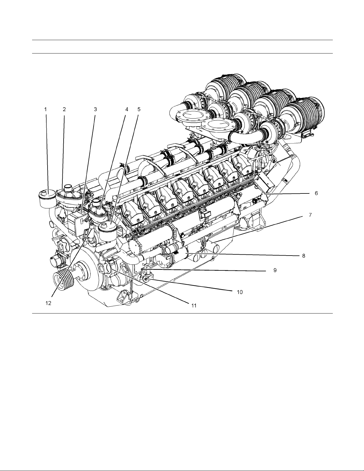
Illustration 1 0
Left side view of engine
(1) Engine crankcase brea ther ( A Bank)
(2) Thermostat housing (A Bank)
(3) Electronic governor actuator
(4) Thermostat housing (B Bank)
(5) Engine crankcase breather (B Bank)
(6) Air shutoff valve (B Bank)
(7) 3x Oil fi lters (B B ank)
(8) Oil cooler
g02029553
(9) Oil level gauge (Dipstick)
(10) Oil filler
(11) Water pump
(12) Stop solenoid
Page 15

SEBU8604 15
Product Information Section
Model Views
Illustration 11
Right side view of engine
(13) Air cleaner
(14) Restriction indicator for air cleaner
(15) Turbocharger
(16) Electronic governor control unit
(17) Alternator
(18) Fuel filters
(19) Oil drain plug
(20) Fuel priming pump
(21) Oil cooler (A B ank)
(22) 3x Oil filters (A Bank)
i03754029
Engine Description
The 4016-61 TRG engine model is designed for
power generation. The engine is available with
turbocharged aftercooled aspiration.
g02029554
(23) Starter relay
(24) Starting m otor
(25) Aftercooler
Engine Specifications
Note: The number 1 cylinders are to the front. The
front of the engine is farthest from the flywheel.
nk A cylinders are on the right hand side of the
Ba
engine. Bank B cylinders are on the left hand side of
the engine. To determine the left and right sides of
he engine, stand behind the flywheel and face the
t
dampers.
Page 16

16 SEBU8604
Product Information Section
Model Views
Illustration 12
4016-61 TRG engine model
(A) Bank
(B) Bank
(X) Inlet valves
(Y) Exhaust valves
Table 1
4016-61 Engine Specifications
Cycle 4 Stroke
Number of
Cylinders
Configuration Vee-form
Bore 160 mm (6.299 inch)
e
Strok
Displacement
Compression
Ratio
Rotation
(flywheel end)
Firing Order
Inlet Valve Lash
(Cold)
Exhaust Valve
Lash (Cold)
190 mm
61.123 L (3729.954 in
Counterclockwise
1A-1B-3A-3B-7A-7B-5A-5B-8A-8B-
6A-6B-2A-2B-4A-4B
0.40 mm (0.016 inch)
0.40 mm (0.016 inch)
16
(7.480 inch)
13:1
g01210841
3
)
The engine lubr
icating oil is supplied by a gear-driven
pump. The lubrication oil is cooled and filtered.
Bypass valves provide unrestricted flow of lubrication
oil to the engi
nepartswhenoilviscosityishigh.
Bypass valves can also provide unrestricted flow
of lubrication oil to the engine parts if the oil filter
element shou
ld become plugged.
Engine efficiency, efficiency of emission controls, and
engine perf
ormance depend on adherence to proper
operation and maintenance recommendations.
Engine performance and efficiency also depend on
the use of re
commended fuels, lubrication oils, and
coolants. Refer to this Operation and Maintenance
Manual, “Maintenance Interval Schedule” for more
informati
on on maintenance items.
Engine Cooling and Lubrication
The cooling system consists of the following
components:
Gear-driven water pumps
•
Water temperature regulators which regulate the
•
engine coolant temperature
Gear-driven oil pump (gear type)
•
Oil coolers
•
Page 17

SEBU8604 17
Product Information Section
Product Identification Information
Product Identification
Information
i03754088
Plate Locations and Film
Locations
Engine Identification
Perkins engines are identified by an engine serial
number.
A typical example of an engine serial number is
DGB R**** U00001M.
D
_________________________________________ Made in Stafford
____________________________________ Application (Table 2)
G
________________________________ Type of engine (Table 3)
B
_________________________ Number of cylinders(Table 4)
R
__________________________________Fixed build number
*****
____________________________ Built in the United Kingdom
U
Table 3
Type of engine (Diesel)
F TG
L
A
B
D
M
K
N
P
R
S TEG3
W TRG2
X TGR3
F
E
G 4016-E61-TRS
H
J
TAG
TAG1
TAG2
TAG3
TWG
TWG2
TWG3
TRG1
TEG2
Type of engine (Gas)
Gas unit
TESI
TESI Combined Heat and Power unit
TRS Combined Heat and Power Unit
TRS Gas Unit
00001
M
Table 2
____________________________________Engine Number
____________________________________ Year of Manufacture
Application
G Genset
I
Gas
Table 4
Number of Cylinders
F 6
H 8
M 12
R 16
Perkins dealers and Perkins distributors require all of
these numbers in order to determine the components
that were included in the engine. This permits
accurate identification of replacement part numbers.
Page 18

18 SEBU8604
Product Information Section
Product Identification Information
Serial Number Plate
Illustration 13
Serial number plate
The engine serial number plate contains the following
information:
Place of manufacture
•
Telephone number of manufacturer
•
Fax number of manufacturer
•
Type of engine
•
Engine serial number
•
Rated speed
•
Power output
•
Engine timing
•
Rating
•
g01266904
Illustration 14
Typical example
The serial number plate (1) on a engine is located on
the left side of the cylinder block (bank B).
g02029586
Page 19

SEBU8604 19
Operation Section
Lifting and Storage
Operation Section
Lifting and Storage
i03880885
Engine Lifting
NOTICE
Never bend the eyebolts and the brackets. Only load
the eyebolts and the brackets under tension. Remember that the capacity of an eyebolt is less as the angle
between the supporting members and the object becomes less than 90 degrees.
When it is necessary to remove a component at an
angle, only use a link bracket that is properly rated for
the weight.
lustration 15
Il
Typical examp le
Use a hoist to remove heavy components. Use a
lifting beam (A) to lift the engine. All supporting
embers (chains and cables) should be parallel
m
to each other. The chains and cables should be
perpendicular to the top of the object that is being
lifted.
g02126835
Page 20

20 SEBU8604
Operation Section
Lifting and Storage
Illustration 1 6
(1) Front lifting eyes (2) Rear lifting eye
ToremovetheengineONLY,usetheliftingeyesthat
are shown in illustration 16. If necessary, remove
engine components in order to avoid damage from
the lifting device.
g02131153
Lifting eyes are designed and installed for specific
engine arrangements. Alterations to the lifting eyes
and/or the engine make the lifting eyes and the lifting
fixtures obsolete. If alterations are made, ensure
that correct lifting devices are provided. Consult
your Perkins dealer or your Perkins distributor for
information regarding fixtures for correct engine
lifting.
Illustration 17
g02130795
Note: The lifting eye (3) must NOT b e used in
order to lift the engine. The lifting eye (3) has
not been designed in order to lift the engine. The
lifting eye is used in factory assembly of engine
components.
Page 21

SEBU8604 21
Operation Section
Lifting and Storage
i03781209
Engine Storage
Refer to Perki
ST16 3UB for information on engine storage.
There are thr
Level “A, B and C”.
ns Engine Company Limited, Stafford,
ee different levels of engine storage.
Level “A ”
Level “A” wi
engines and for gas engines. This level is used for
engines that are transported in a container or by a
truck.
ll give protection for 12 months for diesel
Level “B ”
This level is additional to level “A”. Level “B ” will
give prot
from −15° to +55°C (5° to 99°F) and “90%” relative
humidity, for a maximum of 2 year.
ection under normal conditions of storage
Level “C ”
This level is additional to level “B”. Level “C” will
give protection for five years in tropical or in arctic
es. Level “C” also meets MOD NES 724
climat
Level “J” for Europe, when engines are stored in an
unheated building or in the open under a waterproof
cover.
Page 22

22 SEBU8604
Operation Section
Features and Controls
Features and Controls
i03882309
Monitoring System
The engine is equipped with sensors or switches to
monitor the following parameters:
Coolant temperature (Switch)
•
Oil pressure (Switch)
•
Intake manifold boost pressure (Sensor)
•
Exhaust temperature Sensors
•
Engine speed (Sensor)
•
Engine overspeed (Sensor or Switch)
•
Sensors and Electrical
Components
Sensor Locations
i03781211
Illustration 1 8
(1) Electronic control unit (ECU)
(2) Coolant tempe rature sensor
(3) Boost pressure sensor
(4) Oil pressure switch
(5) High turbine inlet temperature shutdown
sensor (A bank)
(6) Thermocouple
(7) Speed sensor
g02088773
(8) Overspeed sensor
(9) High turbine inlet te mperature shutdown
sensor (B bank)
(10) Oil pressure switch
Page 23

SEBU8604 23
Operation Section
Features and Controls
The Illustrati
ons show the typical locations of the
sensors on the engine. Specific engines may appear
different from the illustrations due to differences in
applications
Coolant Tempe
.
rature Sensor
The boost press
ure sensor (3) measures the
pressure in the inlet air manifold. A signal is sent to
the ECU (1).
Illustration 19
Coolant temperature switches
g02088775
The coolant temperature switches (2) monitor the
engine coolant temperature. The switches are
supplied for connecting to an OEM supplied panel.
Boost Pressure Sensors
llustration 20
I
Boost pressure sensor
g02125658
Page 24

24 SEBU8604
Operation Section
Features and Controls
Engine Oil Pressure Switch
Illustration 2 1
Engine oil pressure sensor
(4) Oil pressure sensor (A Bank) (9) Oil pressure sensor (B Bank)
An oil pressure sensor is installed on both side of
the engine. The engine oil pressure sensors are
mounted in the main oil gallery. The engine oil
pressure sensors are supplied for connecting to an
OEM supplied panel.
High Turbine Inlet Temperature
Shutdown Sensor
g02041294
Illustration 2 2
(5) High turbine inlet temperature shutdown
sensor (A bank)
(8) High turbine inlet temperature shutdown
sensor (B bank)
02124274
g
Page 25

SEBU8604 25
Operation Section
Features and Controls
Illustration 23
Thermocouple
g02123434
Four thermocouples are installed. One thermocouple
is installed in each of the exhaust manifolds. There
are two high turbine inlet temperature shutdown
sensors. One sensor monitors each engine bank.
A sensor monitors two thermocouples. If high
temperatures are indicated the engine will be
shutdown.
The speed senso
r(7)shouldbeservicedat
the required maintenance interval. Refer to the
Operation and Maintenance Manual, “Speed Sensor,
Clean/Inspec
t”.
Failure of the Speed Sensor
If the ECU (1) does not receive a signal from the
speed sensor (4), the engine cannot run.
If the ECU does not receive a signal from the speed
sensor (7), the engine will shut down. A faulty speed
sensor shou
ld be replaced.
Note: Intermittent failure of the speed sensor will
cause the e
ngine to run erratically. This may also
cause overspeed.
Overspeed Sensor
Speed Sensor
Illustration 24
eed sensor
Sp
g02123433
Illustration 25
Overspeed sensor
g01231518
The signal from the overspeed sensor (8) is
connected to the overspeed switch or the overspeed
circuit in the OEM supplied panel.
The location of the sensor can vary depending on
the application.
Page 26

26 SEBU8604
Operation Section
Engine Starting
Engine Starting
i03873029
Before Start ing Engine
Before the e
daily maintenance and any other periodic
maintenance that is due. Refer to the Operation
and Mainte
Schedule” for more information.
Note: Do no
controls if there is a “DO NOT OPERATE” warning
tag or similar warning tag attached to the start switch
or to the c
1. Open the fuel supply valves and open the return
lines (i
2. If the engine has not been started for several
weeks, f
system. Also, when fuel filters have been changed,
some air pockets will be trapped in the engine.
In thes
to the Operation and Maintenance Manual, “Fuel
System-Prime”formoreinformation.
ngine is started, perform the required
nance Manual, “Maintenance Interval
t start the engine or move any of the
ontrols.
f equipped).
uel may have drained from the fuel
e instances, prime the fuel system. Refer
a. Ensure that the
position by disconnecting the speed pickup
connector on the governor control.
b. Turn the keyswitch to the START position.
Hold the keyswitch in this position until
the oil press
(14.5040 psi). Continue to hold the keyswitch
in the START position for an additional 10
seconds.
Note: The keyswitch is part of the OEM supplied
panel. The e
Refer t o OEM supplied instructions for the correct
starting procedure.
c. Turn the keyswitch to the STOP position.
d. Reconnect
The engine is now ready to run.
xact procedure for starting may vary.
governor stays in the STOP
ure gauge indicates 100 kPa
the speed pickup connector.
i02415221
Starting the Engine
Normal Engine Starting Procedure
Illustration 26
3. Ensure that the two air shutoff valves (1) are in
the OPEN position.
4. If the engine has not been started for more than
three months, the engine oil system must be
primed. Follow Steps 4.a through 4.d in order to
prime the engine oil system.
g02114793
Note: When possible, ensure that the engine is not
started under load.
1. Turn the keyswitch to the START position. The
engine should start immediately.
2. Allow the keyswitch to return to the RUN position
after the engine starts.
If the engine does not start after 10 seconds,
return the keyswitch in the RUN position for 10
seconds. Then repeat Steps 1 and 2.
Note: If the engine fails to start after three attempts,
investigate the cause.
3. After the engine has started follow Steps 3.a
through 3.d.
a. Check the oil pressure.
b. Inspect the engine for leaks.
c. Ensure that the batteries for the engine are
receiving a charge.
d. After the engine has run for five minutes, check
the engine monitoring systems. Ensure that the
engine is operating correctly before the load
is applied.
Page 27

SEBU8604 27
Operation Section
Engine Starting
i02415223
Cold Weath er Starting
Do not use aerosol types of starting aids such as
ether. Such use could result in an explosion and
personal injury.
Startability will be improved at temperatures below
+10 °C (+50 °F) from the use of a jacket water heater
or extra battery capacity.
Page 28

28 SEBU8604
Operation Section
Engine Operation
Engine Operation
i02415225
Engine Operation
Correct ope
in obtaining the maximum life and economy of
the engine. If the directions in the Operation and
Maintenan
minimized and engine service life can be maximized.
Gauge read
and the data should be recorded frequently while
the engine is operating. Comparing the data over
time will
gauge.Comparingdataovertimewillalsohelp
detect abnormal operating developments. Significant
changes
ration and maintenance are key factors
ce Manual are followed, costs can be
ings (if equipped) should be observed
help to determine normal readings for each
in the readings should be investigated.
i02415226
Fuel Conservation P ractices
The efficiency
economy. Perkins design and technology in
manufacturing provides maximum fuel efficiency in
all applicat
in order to attain optimum performance for the life
of the engine.
Avoid spilling fuel. Fuel expands when the fuel is
•
warmed up. The fuel may overflow from the fuel
tank. Insp
lines, as needed.
Be aware of
•
Use only the recommended fuels.
Avoid unn
•
engine is not under load, the engine should be
shut down.
Observe the air cleaner service indicator frequently.
•
The air cleaner elements should be replaced when
the air c
of the engine can affect the fuel
ions. Follow the recommended procedures
ect fuel lines for leaks. Repair the fuel
the properties of the different fuels.
ecessary running at a low load. If the
leaner elements are dirty.
Maintain the electrical systems. One damaged
•
battery
consume excess power and excess fuel.
Ensure
•
The drive belts should be in good condition.
Ensur
•
tight. The connections should not leak.
Ensur
•
working order.
Cold
•
from the jacket water system and the exhaust
system, when possible. Keep cooling system
comp
components in good repair. Never operate the
engine without water temperature regulators.
All
temperatures.
cell will overwork the alternator. This will
that the drive belts are correctly adjusted.
e that all of the connections of the hoses are
e that the driven equipment is in good
engines consume excess fuel. Utilize heat
onents clean and keep cooling system
of these items will help maintain operating
Page 29

SEBU8604 29
Operation Section
Engine Stopping
Engine Stopping
i02415227
Stopping the Eng ine
Note: Indiv
control systems. Ensure that the shutoff procedures
are understood. Use the following general guidelines
in order to
1. Remove the load from the engine. Allow the
engine to r
cool the engine.
2. Stop the e
according to the shutoff system on the engine and
turn the ignition key switch to the OFF position.
If neces
provided by the OEM.
Emergency Stopping
Emergency shutoff controls are for EMERGENCY use
ONLY. DO NOT use emergency shutoff devices or
contr
idual applications will have different
stop the engine.
un off load for five minutes in order to
ngine after the cool down period
sary, refer to the instructions that are
NOTIC
ols for normal stopping procedure.
E
i02415230
i02415231
After Stopping Engine
Note: Before y
the engine for at least 10 minutes in order to allow
the engine oil to return to the oil pan.
If the engine is equipped with a service hour meter,
•
note the reading. Perform the maintenance that
is in the Ope
“Maintenance Interval Schedule”.
Check the c
•
between the “MIN” mark and the “MAX” mark on
the engine oil level gauge.
If necessary, perform minor adjustments. Repair
•
any leaks from the low pressure fuel system and
from the c
Fill the fuel tank in order to help prevent
•
accumula
the fuel tank.
Only use antifreeze/coolant mixtures recommended in
the Coo
and Maintenance Manual. Failure to do so can cause
engine damage.
ou check the engine oil, do not operate
ration and Maintenance Manual,
rankcase oil level. Maintain the oil level
ooling, lubrication or air systems.
tion of moisture in the fuel. Do not overfill
NOTICE
lant Specifications that are in the Operation
The engine should be equipped with an emergency
button. For more information about the
stop
emergency stop button, refer to the OEM information.
ure that any components for the external system
Ens
that support the engine operation are secured after
the engine is stopped.
In the event of an overspeed condition, the air shutoff
valves will operate. After operation, the air shutoff
lves must be manually reset.
va
Pressurized System: Hot coolant can cause serious burns. To open the cooling system filler cap,
stop the engine and wait until the cooling system
components are cool. Loosen the cooling system
pressure cap slowly in order to relieve the pressure.
Allow the engine to cool. Check the coolant level.
•
Check the coolant for correct antifreeze protection
•
and the correct corrosion protection. Add the
correct coolant/water mixture, if necessary.
Perform all required periodic maintenance on all
•
driven equipment. This maintenance is outlined in
the instructions from the OEM.
Page 30

30 SEBU8604
Maintenance Section
Refill Capacities
Maintenance Section
Refill Capacities
i03754119
Refill C apacities
Lubrication S ystem
The refill capacities for the engine crankcase
reflect the approximate capacity of the crankcase
or sump plus standard oil filters. Auxiliary oil filter
systems will require additional oil. Refer to the OEM
specifications for the capacity of the auxiliary oil filter.
Refer to the Operation and Maintenance Manual,
“Maintenance Section” for more information on
Lubricant Specifications.
Table 5
Engine
Refill Capacities
Compartment or System 4016 TRG
Crankcase Oil Sump
(1)
These values are the total capa cities for the crankcase oil
sump which includes the standard factory installed oil filters
and oil coolers. Engines with auxiliary oil filters w ill require
additional oil. Refer to the OEM specifications for the capacity
of the auxiliary oil filter.
(1)
238 L (52.4 Imp gal)
Fuel System
Refer to the OEM specifications for additional
information on the capacity of the Fuel System.
Table 7
Engine
Refill Capacities
Compartment or System 4016
Minimum Cap
Tan k
Fluid Re c o
acity of Fuel
22500 L (4949 Imp gal)
mmendations
i03837413
(Cooling System
Specifications)
General Coolant Information
NOTICE
Never add coolant to an overheated engine. Engine
damage could result. Allow the engine to cool first.
NOTICE
If the engine is to be stored in, or shipped to an area
with below freezing temperatures, the cooling system
must be either protected to the lowest outside temperature or drained completely to prevent damage.
Cooling System
Refer to the OEM specifications for the External
System capacity. This capacity information will be
ed in order to determine the amount of coolant
need
and antifreeze that is required for the Total Cooling
System.
le 6
Tab
ine
Eng
Refill capacities
Compartment or System Liters
Engine cooling system 95
Secondary cooling system
External System Per OEM
(1)
The volume of coolant that is given in this table is for the
engine. The volume for the total cooling capacity w ill depend
on the application.
(2)
Refer to the OEM specifications .
(1)
(2)
50
-
NOTICE
uently check the specific gravity of the coolant for
Freq
proper freeze protection or for anti-boil protection.
Clean the cooling system for the following reasons:
Contamination of the cooling system
•
Overheating of the engine
•
Foaming of the coolant
•
NOTICE
Never operate an engine without water temperature
regulators in the cooling system. Water temperature
regulators help to maintain the engine coolant at the
proper operating temperature. Cooling system problems can develop without water temperature regulators.
Page 31

SEBU8604 31
Maintenance Section
Refill Capacities
Many engine fai
system. The following problems are related to cooling
system failures: Overheating, leakage of the water
pump, and plug
These failures can be avoided with correct cooling
system maint
as important as maintenance of the fuel system and
the lubrication system. Quality of the coolant is as
important a
oil.
Coolant is n
Water, additives, and glycol.
lures are related to the cooling
ged radiators or heat exchangers.
enance. Cooling system maintenance is
s the quality of the fuel and the lubricating
ormally composed of three elements:
Water
Water is used in the cooling system in order to
transfer h
Distilled water or deionized w ater is
recommen
DO NOT use the following types of water in cooling
systems
conditioned with salt, and sea water.
If disti
use water with the properties that are listed in T able 8.
Table 8
For a water analysis, consult one of the following
sources:
Local water utility company
•
Agricultural agent
•
eat.
ded for use in engine cooling systems.
: Hard water, softened water that has been
lled water or deionized water is not available,
Acceptable Water
Property Maximum Limit
Chloride (Cl) 40 mg/L
Sulfate (SO4) 100 mg/L
Total Hardness 170 mg/L
Tot a
lSolids
Acidity
pH of 5.5 to 9.0
340 m
g/L
Formation of mi
•
Rust
•
Scale
•
Foaming of th
•
Many additives are depleted during engine operation.
These addit
Additives must be added at the correct concentration.
Overconcen
inhibitors to drop out-of-solution. The deposits can
enable the following problems to occur:
Formation of gel compounds
•
Reduction
•
Leakage of the water pump seal
•
Plugging of radiators, coolers, and small passages
•
neral deposits
ecoolant
ives must be replaced periodically.
tration of additives can cause the
of heat transfer
Glycol
Glycol in the coolant helps to provide protection
against
•
•
•
For optimum performance, Perkins recommends a
1:1 mi
Note: Use a mixture that will provide protection
again
Note: 100 percent pure glycol will freeze at a
temp
Most conventional coolants use ethylene glycol.
Prop
with water, ethylene and propylene glycol provide
similar protection against freezing and boiling“. Refer
to T
the following conditions:
Boiling
Freezing
tion of the water pump
Cavita
xture of a water/glycol solution.
st the lowest ambient temperature.
erature of −23 °C (−9°F).
ylene glycol may also be used. In a 1:1 mixture
ables 9 and 10.”.
Independent laboratory
•
Additives
Additives help to protect the metal surfaces of
the cooling system. A lack of coolant additives or
insufficient amounts of additives enable the following
conditions to occur:
Corrosion
•
Table 9
Concentration
50 Percent
60 Percent
Ethylene Glycol
Freeze
Protection
−36 °C (−33 °F) 106 °C (223 °F)
−51 °C (−60 °F) 111 °C (232 °F)
Boil
Protection
Page 32

32 SEBU8604
Maintenance Section
Refill Capacities
NOTICE
Do not use prop
ylene glycol in concentrations that exceed 50 percent glycol because of the reduced heat
transfer capability of propylene glycol. Use ethylene
glycol in cond
itions that require additional protection
against boiling or freezing.
Table 10
Propylene Glycol
Concentration
50 Percent −29 °C (−20 °F) 106 °C (223 °F)
Freeze
Protection
Anti-Boil
Protection
To check the concentration of glycol in the coolant,
measure the specific gravity of the coolant.
Coolant Recommendations
The following two coolants are used in Perkins diesel
engines:
Preferred – Perkins Extended Life Coolant (ELC)
Extended Life C
oolant (ELC)
Perkins provides Extended Life Coolant (ELC) for
useinthefoll
Heavy-duty spark ignited gas engines
•
Heavy-duty diesel engines
•
Automotive
•
owing applications:
applications
The anti-corrosion package for ELC is different from
the anti-co
rrosion package for other coolants. ELC
is an ethylene glycol base coolant. However, ELC
contains organic corrosion inhibitors and antifoam
agents wit
h low amounts of nitrite. Perkins ELC
has been formulated with the correct amount of
these additives in order to provide superior corrosion
protectio
n for all metals in engine cooling systems.
ELC is available in a 1:1 premixed cooling solution
with dist
illed water. The Premixed ELC provides
freeze protection to −36 °C (−33 °F). The Premixed
ELC is recommended for the initial fill of the cooling
system. T
he Premixed ELC is also recommended for
topping off the cooling system.
Acceptable – A commercial heavy-duty coolant that
meets “ASTM D4985” specifications
NOTICE
Do not use a commercial coolant/antifreeze that only meets the ASTM D3306 specification. This type of
nt/antifreeze is made for light automotive appli-
coola
cations.
Perkins recommends a 1:1 mixture of water and
ol. This mixture of water and glycol will provide
glyc
optimum heavy-duty performance as a coolant.
e: A commercial heavy-duty coolant that
Not
meets “ASTM D4985” specifications MAY require a
treatment with an SCA at the initial fill. Read the label
he instructions that are provided by the OEM of
or t
the product.
Table 11
Coolant Service Life
Coolant Type Service Life
Perkins ELC
Commercial Heavy-Duty
oolant that meets
C
“ASTM D4985”
Perkins POWERPART
Commercial SCA and
SCA
Water
6,000 Service Hours or
Three Years
3000 Service Hours or
Two Years
3000 Service Hours or
Two Years
3000 Service Hours or
Two Years
ELC Conc
entrate is also available. ELC Concentrate
canbeusedtolowerthefreezingpointto−51 °C
(−60 °F) for arctic conditions.
Containers of several sizes are available. Consult
your Perkins dealer or your Perkins distributor for the
part nu
ELC Co
mbers.
oling System Maintenance
Correct additions to the Extended Life
Coola
Use only Perkins products for pre-mixed or concentrated coolants.
Use only Perkins Extender with Extended Life
Coolant.
Mixing Extended Life Coolant with other products reduces the Extended Life Coolant service life. Failure to
follow the recommendations can reduce cooling system components life unless appropriate corrective action is performed.
In
the coolant and the additives, you must maintain
the recommended concentration of Extended Life
C
lowers the proportion of additive. This will lower the
ability of the coolant to protect the system from pitting,
rom cavitation, from erosion, and from deposits.
f
nt
NOTICE
order to maintain the correct balance between
oolant (ELC). Lowering the proportion of coolant
Page 33

SEBU8604 33
Maintenance Section
Refill Capacities
NOTICE
Do not use a con
system that is filled with Extended Life Coolant (ELC).
Do not use stan
(SCA). Only use ELC Extender in cooling systems that
are filled with ELC.
When using Perkins ELC, do not use standard SCA's
or SCA filters.
ventional coolant to top-off a cooling
dard supplemental coolant additive
NOTICE
ELC Cooling System Cleaning
Note: If the cooling system is already using ELC,
cleaning agents are not required to be used at
the specified coolant change interval. Cleaning
agents are only required if the system has been
contaminated by the addition of some other type of
coolant or by cooling system damage.
Clean water is the only cleaning agent that is required
when ELC is drained from the cooling system.
After the cooling system is drained and after the
cooling system is refilled, install the filler cap. Operate
the engine until the coolant level reaches the normal
operating temperature. Shut the engine down using
the normal shutdown procedure.
As needed, add the coolant mixture in order to fill the
system to the specified level. Install the filler cap.
Changing to Perkins ELC
4. Use Perkins cle
the instruction on the label.
5. Drain the clea
the cooling system with clean water.
6. Fill the cool
operate the engine until the engine is warmed to
49° to 66°C (120° to 150°F).
Incorrect or incomplete flushing of the cooling system
can result in damage to copper and other metal components.
To avoid damage to the cooling system, make sure to
completel
Continue to flush the system until all the signs of the
cleaning agent are gone.
7. Shut down the engine by using the normal
Note: Th
flushed from the cooling system. Cooling system
cleaner that is left in the system will contaminate the
coolan
system.
8. Repeat
9. Fill t
y flush the cooling system with clear water.
shutdown procedure. Drain the cooling system
intoasu
system w ith clean water.
the system is completely clean.
ELC.
itable container and flush the cooling
e cooling system cleaner must be thoroughly
t. The cleaner may also corrode the cooling
the Steps 6 and repeat the steps 7 until
hecoolingsystemwiththePerkinsPremixed
aner to clean the system. Follow
ner into a suitable container. Flush
ingsystemwithcleanwaterand
NOTICE
To change from heavy-duty coolant to the Perkins
ELC, perform the following steps:
NOTICE
Care must be taken to ensure that all fluids are
contained during performance of inspection, maintenance, testing, adjusting and the repair of the
product. Be prepared to collect the fluidwithsuitable
containers before opening any compartment or disassembling any component containing fluids.
Dispose of all fluids according to local regulations and
mandates.
1. Drain the coolant into a suitable container.
2. Dispose of the coolant according to local
regulations.
3. Flush the system with clean water in order to
remove any debris.
ELC C
Mixing ELC with other products reduces the effectiveness of the ELC and shortens the ELC service life.
Use only Perkins Products for premixed or concentrate coolants. Use only Perkins ELC extender with
Perkins ELC. Failure to follow these recommendations can result in shortened cooling system component life.
ELC cooling systems can withstand contamination to
a maximum of ten percent of conventional heavy-duty
coolant or SCA. If the contamination exceeds ten
percent of the total system capacity, perform ONE of
the following procedures:
•
ooling System Contamination
NOTICE
Drain the cooling system into a suitable container.
Dispose of the coolant according to local
regulations. Flush the system with clean water. Fill
the system with the Perkins ELC.
Page 34

34 SEBU8604
Maintenance Section
Refill Capacities
Drain a portion
•
of the cooling system into a suitable
container according to local regulations. Then, fill
the cooling system with premixed ELC. This should
lower the cont
Maintain the system as a conventional Heavy-Duty
•
Coolant. Tre
aminationtolessthan10percent.
atthesystemwithanSCA.Change
the coolant at the interval that is recommended for
the conventional Heavy-Duty Coolant.
Commercial Heavy-Duty Coolant and
SCA
NOTICE
Commercial Heavy-Duty Coolant which contains
Amine as part of the corrision protection system must
not be used.
NOTICE
Never operate an engine without water temperature
regulators in the cooling system. Water temperature
regulat
ors help to maintain the engine coolant at the
correct operating temperature. Cooling system problems can develop without water temperature regulators.
Check the coolant (glycol concentration) in order
to ensure adequate protection against boiling
zing. Perkins recommends the use of a
or free
refractometer for checking the glycol concentration.
ns engine cooling systems should be tested
Perki
at 500 hour intervals for the concentration of
Supplemental Coolant Additive (SCA).
Additions of SCA are based on the results of the test.
An SCA that is liquid may be needed at 500 hour
rvals.
inte
Refer to Table 12 for part numbers and for quantities
A.
of SC
Table 12
Perkins Liquid SCA
Part Number Quantity
21825735 10
Adding the SCA to Heavy-Duty C oolant
at the Initial Fill
Use the equatio
nthatisinTable13todeterminethe
amount of Perkins SCA that is required when the
cooling system is initially filled.
Table 13
Equation For Adding The SCA To The Heavy-Duty
Coolant At The Initial Fill
V×0.045=X
V is the total volume of the cooling system.
X is the amount of SCA that is required.
Table 14 is an example for using the equation that
is in Table 13.
Table 14
Example Of The Equation For Adding The SCA To
The Heavy-
Tot al Vo l ume
of the Cooling
System (V
15 L (4 US gal) × 0.045 0.7 L (24 oz)
Duty Coolant At The Initial Fill
Multiplication
Factor
)
Amount of SCA
that is Required
(X)
Adding The SCA to The Heavy-Duty
Coolant For Maintenance
Heavy-duty coolant of all types REQUIRE periodic
additions of an SCA.
Test the coolant periodically for the concentration
of SCA. For the interval, refer to the Operation
and Maintenance Manual, “Maintenance Interval
Schedule” (Maintenance Section). Test the
concentration of SCA.
Additions of SCA are based on the results of the
test. The size of the cooling system determines the
amount of SCA that is needed.
Use the equation that is in Table 15 to determine the
amount of Perkins SCA that is required, if necessary:
Table 15
Equation For Adding The SCA To The Heavy-Duty
V is the total volume of the cooling system.
X is the amount of SCA that is required.
Coolant For Maintenance
V×0.014=X
Commercial heavy-duty coolant that meets “ASTM
D4985” specifications MAY require an addition of
SCA at the initial fill. Read the label or the instructions
that are provided by the OEM of the product.
Table 16 is an example for using the equation that
is in Table 15.
Page 35

SEBU8604 35
Maintenance Section
Refill Capacities
Table 16
Example Of The Equation For Adding The SCA To
The Heavy-Duty Coolant For Maintenance
Total Volume
of the Cooling
System (V)
15 L (4 US gal) × 0.014 0.2 L (7 oz)
Multiplication
Factor
Amount of SCA
that is Required
(X)
Cleaning the System of Heavy-Duty
Coolant
Perkins cooling system cleaners are designed
to clean the cooling system of harmful scale
and corrosion. Perkins cooling system cleaners
dissolve mineral scale, corrosion products, light oil
contamination and sludge.
Clean the cooling system after used coolant is
•
drained or before the cooling system is filled with
new coolant.
Clean the cooling system whenever the coolant is
•
contaminated or whenever the coolant is foaming.
i03837412
Fluid Recommendations
(Fuel Specifications)
Fuel Recommendations
To get the correct power and performance from
the engine, use a fuel of the correct quality. The
recommended fuel specification for Perkins engines
is shown below:
Class A1 Fuels
Cetane number_________________________ ___________ ___50
•
Viscosity___________ 1.5to5.0cStat40°C(104°F)
•
Carbon residue__________________________________0.20%
•
Ramsbottom on 10% reidue
Sulfur content___________ 0.05% of mass, maximum
•
Distillation___________________56% at 350 °C (662 °F)
•
Lubricity_________________________ _____460 micrometers
•
maximum wear scar on “ISO 12156 - 1”
Class A2 Fuels
Viscosity____
•
Carbon residue__________________________________0.20%
•
Ramsbottom on
Sulfur content___________0.05% of mass, maximum
•
Distillation___________________ 56% at 350 °C (662 °F)
•
Lubricity_
•
maximum wear scar on “ISO 12156 - 1”
Cetane numb
This indicates the properties of ignition of the fuel.
Fuel with a
cause of problems during cold start. This will affect
combustion.
Viscosity
This is th
resistance is outside the limits, the engine and the
engine starting performance in particular can be
affected
Sulfur
High sulfur content of the fuel is not normally found
in Europe, North America or Australasia. This can
cause en
are available, it will be necessary that high alkaline
lubricating oil is used in the engine or that the
lubric
Distillation
This is an indication of the mixture of different
hydrocarbons in the fuel. A high ratio of light weight
hydro
combustion.
Lubr
This is the capability of the fuel to prevent pump wear.
Diesel engines have the ability to burn a variety
of fuels. These fuels are divided into two general
gro
•
•
Gr
“DERV to EN59 0”
.
ating oil change interval is reduced.
carbons can affect the characteristics of
icity
ups:
Group 1 (preferred fuels)
Group 2 (permissible fuels)
oup 1 (preferred fuels): Specification
_______
_____________________________
er
low cetane number can be the root
eresistancetoflow of a fluid. If this
gine wear. When only high sulfur fuels
1.5to5.5cStat40°C(104°F)
10% reidue
460 micrometers
Cetane number_________________________ ___________ ___45
•
Page 36

36 SEBU8604
Maintenance Section
Refill Capacities
Note: Only use A
rctic fuels when the temperature is
below 0 °C (32 °F). Do not use Arctic fuels when the
ambient temperature is above 0 °C (32 °F). To ensure
thatthetimep
eriod between cranking the engine and
first fire is kept to a minimum, only use fuel of the
correct viscosity and at the correct temperature.
Gas oil to “BS29 Class A2”
Note: If low
sulfur or low sulfur aromatic fuels are
used, then fuel additives can be used to increase
lubricity.
Group 2 (permissible fuels): Specification
These fuel
specifications are considered acceptable
for issues of warranty. However,these fuels may
reduce the life of the engine, the engine's maximum
power and t
he engine's fuel efficiency.
“ASTM D975 - 91 Class 1D”
“JP7, Mil T38219”
“NATO F63
”
NOTICE
These fuels should have a wear scar value of 650
micrometers maximum *HFRR to ISO 12156 - 1.*
Low tem
perature fuels
Special fuels for use in cold weather may be available
gine operation at temperatures below 0 °C
for en
(32 °F). These fuels limit the formation of wax in the
fuel oil at low temperatures. If wax forms in the fuel
his could stop the flow of fuel oil through the filter.
oil, t
Note: These fuels that lack lubricity may cause the
owing problems:
foll
Low engine power
•
Refer to the fol
lowing fuel specifications for
North America.
The preferred
fuels provide maximum engine service
life and performance. The preferred fuels are distillate
fuels. These fuels are commonly called diesel fuel
or gas oil.
The permissible fuels are crude oils or blended fuels.
Use of these
fuels can result in higher maintenance
costs and in reduced engine service life.
Diesel fuel
s that meet the specifications in Table
17 will help to provide maximum engine service life
and performance. In North America, diesel fuel that
is identifi
ed as No. 2-D in “ASTM D975” generally
meets the specifications. Table 17 is for diesel fuels
that are distilled from crude oil. Diesel fuels from
other sour
ces could exhibit detrimental properties
that are not defined or controlled by this specification.
Table 17
Perkins Specifications for Distillate Diesel Fuel
Specifications
Aromatics
Ash
Carbon Residue
on 10% Bottoms
Cetane Number
Cloud Point
Requirements
35% maximum “D1319”
0.02% maximum
(weight)
0.35% maximum
(weight)
40 minimum (DI
engines)
The cloud
point must not
exceed the
lowest expected
ambient
temperature.
ASTM Test
“D482”
“D524”
“D613”
-
(continued)
Difficult starting in hot conditions or in cold
•
conditions
White smoke
•
erioration of emissions and misfire at certain
Det
•
operating conditions
ofuel: Specification
Bi
Biofuel: A 5% mix of RME to EN14214 in conventional
el is permitted.
fu
NOTICE
Water emulsion fuels: These fuels are not permitted
Page 37

SEBU8604 37
Maintenance Section
Refill Capacities
(Table 17, contd)
Copper Strip
Corrosion
No. 3 maximum
“D130”
10% at 282 °C
(540 °F)
maximum
Distillation
“D86”
90% at 360 °C
(680 °F)
maximum
Flash Point legal limit
“D93”
30 minimum
API Gravity
“D287”
45 maximum
6°C(10°F)
Pour Point
minimum
below ambient
“D97”
temperature
0.2% maximum “D3605”
(1)
Sulfur
or
“D1552”
2.0 cSt minimum
Kinematic
Viscosity
(2)
and 4.5 cSt
maximum at
“D445”
40 °C (104 °F)
Water and
Sediment
Water
Sediment
Gum and Resins
(3)
0.1% m
0.1% maximum “D1744”
0.05% maximum
(weight)
10 mg per 100
mL maximum
aximum
“D1796”
“D473”
“D381”
0.38 mm
Lubricity
(4)
(0.015 inch)
maximum at
“D6079”
25 °C (77 °F)
(1)
Perkins fuel systems and engine components can operate
on high sulfur fuels. Fuel sulfur levels affect exhaust
emissions. High s ulfur fuels also increase the potential
for c orrosion of internal components. Fuel sulfur levels
above 0.5 percent ma y significantly s horten the oil change
interval. For additional information, see this publication, “Fluid
Recommendations/Engine Oil” topic (M aintenance S ection).
(2)
The values of the fuel viscosity are the values as the fuel
is delivered to the fuel injection pumps. If a fuel with a low
viscosity is used, cooling of the fuel may be required to maintain
a 1.4 cSt v iscosity at the fuel injection pump. Fuels with a high
viscosity might require fuel heaters in order to bring down the
viscosity t o a 20 cS t viscosity.
(3)
Follow the test conditions and pr ocedures for gasoline (motor).
(4)
The lubricity of a fuel is a concern with low sulfur fuel. To
determine the lubricity of the fuel, use either the “ASTM D6078
Scuffing Load Wear Test (SBOCLE)” or the “ASTM D6079 High
Frequency Reciprocating Rig (HFRR)” test. If the lubricity of a
fuel does not meet the minimum requirements, consult your
fuel supplier. Do not treat the fuel without consulting the fuel
supplier. Some additives are not compatible. These additives
can cause problems in the fuel system.
Operating wit
h fuels that do not meet the Perkins recommendations can cause the following effects: Starting difficulty, poor combustion, deposits in the fuel injectors, redu
ced service life of the fuel system, deposits in the combustion chamber, and reduced service life of the engine.
Heavy Fuel Oil (HFO), Residual fuel, or Blended fuel
must NOT be used in Perkins diesel engines. Severe
component wear and component failures will result if
HFO type fuels are used in engines that are configured
to use distillate fuel.
In extreme cold ambient conditions, you may use the
distillate fuels that are specified in Table 18. However,
the fuel that is selected must meet the requirements
that are specified in Table 17. These fuels are
intended to be used in operating temperatures that
are down to −54 °C (−65 °F).
Table 18
Distillate Fuels
Specification Grade
“MIL-T-5624R” JP-5
“ASTM D1655” Jet-A-1
“MIL-T-83133D” JP-8
(1)
The fuels that are listed in this Table may not meet the
requirements that are specified in the “Perkins Specifi cations
for Distillate Diesel Fuel” Table. Consult the supplier for the
recommended additives in order to maintain the correct fuel
lubricity.
These fuels are lighter than the No. 2 grades of fuel.
The cetane number of the fuels in Table 18 must be
at least 40. If the viscosity is below 1.4 cSt at 38 °C
(100 °F), use the fuel only in temperatures below
0°C(32°F).Donotuseanyfuelswithaviscosity
of less than 1.2 cSt at 38 °C (100 °F). Fuel cooling
may be required in order to maintain the minimum
viscosity of 1.4 cSt at the fuel injection pump.
There are many other diesel fuel specifications that
are published by governments and by technological
societies. Usually, those specifications do not
review all the requirements that are addressed
in this specification. To ensure optimum engine
performance, a complete fuel analysis should be
obtained before engine operation. The fuel analysis
should include all of the properties that are listed in
Table 17.
NOTICE
NOTICE
(1)
Page 38

38 SEBU8604
Maintenance Section
Refill Capacities
i03837410
Fluid Recommendations
(General Lubr
icant
Information)
Engine Oil
Commercial Oils
The performance of commercial diesel engine
oils is based on American Petroleum Institute
(API) clas
developed in order to provide commercial lubricants
for a broad range of diesel engines that operate at
various co
Only use commercial oils that meet the following
classific
API CG-4
•
API CH-4
•
In order
oil, refer to the following explanations:
EMA DHD
Association (EMA) has developed lubricant
recommendations as an alternative to the API oil
classi
Guideline that defines a level of oil performance for
these types of diesel engines: high speed, four stroke
cycle
be used in Perkins engines when the following oils
are recommended: API CH-4, API CG-4, and API
CF-4.
performance in comparison to API CG-4 and API
CF-4.
DHD-1 oils will meet the needs of high performance
Perkins diesel engines that are operating in many
appl
used to define DHD-1 are similar to the new API
CH-4 classification. Therefore, these oils will also
mee
low emissions. DHD-1 oils are designed to control the
harmful effects of soot with improved wear resistance
and
These oils will also provide superior piston deposit
control for engines with either two-piece steel pistons
aluminum pistons.
or
sifications. These API classifications are
nditions.
ations:
to make the correct choice of a commercial
-1 – The Engine Manufacturers
fication system. DHD-1 is a Recommended
, heavy-duty, and light duty. DHD-1 oils may
DHD-1 oils are intended to provide superior
ications. The tests and the test limits that are
t the requirements for diesel engines that require
improved resistance to plugging of the oil filter.
All DHD-1 oils m
with the base stock and w ith the viscosity grade of
the finishedcommercialoil.Theuseof“APIBase
Oil Interchan
DHD-1 oils. This feature reduces the variation in
performance that can occur when base stocks are
changed in co
DHD-1 oils are recommended for use in extended oil
change inte
oil. These oil change interval programs are based
on oil analysis. DHD-1 oils are recommended for
conditions
dealer or your Perkins distributor has the specific
guidelines for optimizing oil change intervals.
API CH-4 – API CH-4 oils were developed in order to
meet the requirements of the new high performance
diesel eng
meet the requirements of the low emissions diesel
engines. API CH-4 oils are also acceptable for use
in older d
use high sulfur diesel fuel. API CH-4 oils may be
used in Perkins engines that use API CG-4 and API
CF-4 oils
performance of API CG-4 oils in the following criteria:
deposits on pistons, control of oil consumption, wear
of pisto
and corrosion.
Three ne
CH-4 oil. The first test specifically evaluates deposits
on pistons for engines with the two-piece steel piston.
This te
of oil consumption. A second test is conducted
with moderate oil soot. The second test measures
the fo
cylinder liners, and resistance to corrosion. A third
new test measures the following characteristics with
high l
resistance of the oil in plugging the oil filter, and
control of sludge.
In addition to the new tests, API CH-4 oils have
tougher limits for viscosity control in applications that
gene
oxidation resistance. API CH-4 oils must pass an
additional test (piston deposit) for engines that use
alu
also established for engines that operate in areas
with high sulfur diesel fuel.
All of these improvements allow the API CH-4
oil to achieve optimum oil change intervals. API
CH
change intervals. API CH-4 oils are recommended
for conditions that demand a premium oil. Your
Pe
guidelines for optimizing oil change intervals.
iesel engines and in diesel engines that
. API CH-4 oils will generally exceed the
n rings, valve train wear, viscosity control,
w engine tests were developed for the API
st (piston deposit) also measures the control
llowing criteria: wear of piston rings, wear of
evels of soot in the oil: wear of the valve train,
rate high soot. The oils also have improved
minum pistons (single piece). Oil performance is
-4 oils are recommended for use in extended oil
rkins dealer or your Perkins distributor has specific
ust complete a full test program
ge Guidelines” are not appropriate for
mmercial oil formulations.
rval programs that optimize the life of the
that demand a premium oil. Your Perkins
ines. Also, the oil was designed to
Page 39

SEBU8604 39
Maintenance Section
Refill Capacities
Some commercia
l oils that meet the API
classifications may require reduced oil change
intervals. To determine the oil change interval, closely
monitor the co
ndition of the oil and perform a wear
metal analysis.
NOTICE
Failuretof
ollow these oil recommendations can cause
shortened engine service life due to deposits and/or
excessive wear.
Total Base
Number (TBN) and Fuel Sulfur
Levels for Direct Injection (DI) Diesel
Engines
The Total Base Number (TBN) for an oil depends on
the fuel sulfur level. For direct injection engines that
use disti
must be 10 times the fuel sulfur level. The TBN is
defined by “ASTM D2896”. The minimum TBN of the
oil is 5 r
demonstrates the TBN.
llate fuel, the minimum TBN of the new oil
egardless of fuel sulfur level. Illustration 27
NOTICE
Operating Dir
ect Injection (DI) diesel engines with fuel
sulphur levels over 0.5 percent will require shortened
oil change intervals in order to help maintain adequate
wear protecti
Table 19
Percentage of Sulfur in
the fuel
Lower than 0.5 Normal
0.5to1.0
Greater than 1.0 0.50 of normal
on.
Oil change interval
0.75 of normal
Lubricant Viscosity Recommendations
for Direct Injection (DI) Diesel Engines
The correct SAE viscosity grade of oil is determined
by the minimum ambient temperature during
cold engine start-up, and the maximum ambient
temperature during engine operation.
Refer to Table 20 (minimum temperature) in order
to determine the required oil viscosity for starting a
cold engine.
Illustration 27
(Y) TBN by “ASTM D2896”
(X) Percentage of fuel sulfur by weight
(1) TBN of new oil
(2) Change the oil when the TBN deteriorates to 50 percent of
the original TBN.
g00799818
Use the following guidelines for fuel sulfur levels that
exceed 1.5 percent:
Choose an oil with the highest TBN that meets one
•
of these classifications: EMA DHD-1 and API CH-4.
Reduce the oil change interval. Base the oil
•
change interval on the oil analysis. Ensure that the
oil analysis includes the condition of the oil and a
wear metal analysis.
Excessivepistondepositscanbeproducedbyanoil
with a high TBN. These deposits can lead to a loss
of control of the oil consumption and to the polishing
of the cylinder bore.
Refer to Table 20 (maximum temperature) in order
to select the oil viscosity for engine operation at the
highest ambient temperature that is anticipated.
Generally, use the highest oil viscosity that is
available to meet the requirement for the temperature
at start-up.
Table 20
Engine Oil Viscosity
EMA LRG-1
API CH-4
Viscosity Grade
SAE 10W30
E 15W40
SA
SAE 15W40
SAE 15W40
Ambient Starting
Temperature
Temperatures below
−15 °C (5 °F)
−15 °C (5 °F) to
0 °C (32. °F)
0 °C (32. °F) to
32 °C (89.5 °F)
Temperatures above
32 °C (89.5 °F)
Synthetic Base S tock Oils
Synthetic base oils are acceptable for use in
these engines if these oils meet the performance
requirements that are specified for the engine.
Page 40

40 SEBU8604
Maintenance Section
Refill Capacities
Synthetic base
conventional oils in the following two areas:
Synthetic bas
•
temperatures especially in arctic conditions.
Synthetic ba
•
stability especially at high operating temperatures.
Some synthe
characteristics that enhance the service life of the
oil. Perkins does not recommend the automatic
extending o
oil.
Re-refined
Re-refined base stock oils are acceptable for
use in Perk
performance requirements that are specified by
Perkins. Re-refined base stock oils can be used
exclusiv
new base stock oils. The US military specifications
and the specifications of other heavy equipment
manufac
stock oils that meet the same criteria.
The proc
stock oil should adequately remove all wear metals
that are in the used oil and all the additives that
areint
make re-refined base stock oil generally involves the
process of vacuum distillation and hydrotreating the
used oi
high quality, re-refined base stock oil.
ely in finished oil or in a combination with
turers also allow the use of re-refined base
he used oil. The process that is used to
l. Filtering is adequate for the production of
oils generally perform better than
eoilshaveimprovedflow at low
se oils have improved oxidation
tic base oils have performance
f the oil change intervals for any type of
Base Stock Oils
ins engines if these oils meet the
ess that is used to make re-refined base
Second Choice –
additive package. Although the oil has not been
tested for the requirements of the API license, the oil
must be either
SAE 5W30, or SAE 5W40.
Shortened engine service life could result if second
choice oils are used.
Use an oil that has a CH-4
SAE0W20,SAE0W30,SAE0W40,
NOTICE
Aftermarket Oil Additives
Perkins does not recommend the use of aftermarket
additives in oil. It is not necessary to use aftermarket
additives in order to achieve the engine's maximum
service life or rated performance. Fully formulated,
finished oils consist of base oils and of commercial
additive packages. These additive packages are
blended into the base oils at precise percentages in
order to help provide finished oils with performance
characteristics that meet industry standards.
There are no industry standard tests that evaluate
the performance or the compatibility of aftermarket
additives in finished oil. Aftermarket additives may
not be compatible with the finished oil's additive
package, which could lower the performance of the
finished oil. The aftermarket additive could fail to
mix with the finished oil. This could produce sludge
in the crankcase. Perkins discourages the use of
aftermarket additives in finished oils.
To achieve the best performance from a Perkins
engine, conform to the following guidelines:
cants for Cold Weather
Lubri
When an engine is started and an engine is operated
in amb
multigrade oils that are capable of flowing in low
temperatures.
These oils have lubricant viscosity grades of SAE
10W or SAE 15W.
When an engine is started and operated in ambient
temperatures below −30 °C (−22 °F), use a synthetic
bas
or with a 5W viscosity grade. Use an oil with a pour
point that is lower than −50 °C (−58 °F).
The number of acceptable lubricants is limited in
cold weather conditions. Perkins recommends the
fo
First Choice – Use oil with an EMA DHD-1
Re
an API license. The oil should be either SAE 0W20,
SAE 0W30, SAE 0W40, SAE 5W30, or SAE 5W40
l
ient temperatures below −20 °C (−4°F),use
e stock multigrade oil with an 0W viscosity grade
llowing lubricants for use in cold weather conditions:
commended Guideline. Use a CH-4 oil that has
ubricant viscosity grade.
Select the correct oil, or a commercial oil that meets
•
the “EMA Recommended Guideline on Diesel
Engine Oil” or the recommended API classification.
See the appropriate “Lubricant Viscosities” table in
•
order to find the correct oil viscosity grade for your
engine.
At the specified interval, service the engine. Use
•
new oil and install a new oil filter.
Perform maintenance at the intervals that are
•
specified in the Operation and Maintenance
Manual, “Maintenance Interval Schedule”.
Oil analysis
Oil samples should be taken on a regular basis for the
purpose of oil analysis. Oil analysis will complement
the preventive maintenance program.
Page 41

SEBU8604 41
Maintenance Section
Refill Capacities
The oil analysi
determine oil performance and component wear
rates. Contamination can be identified and measured
through the us
includes the following tests:
The Wear Rate
•
engine's metals. The amount of wear metal and
type of wear metal that is in the oil is analyzed. The
increase in
oil is as important as the quantity of engine wear
metal in the oil.
Tests are conducted in order to detect
•
contamination of the oil by water, glycol or fuel.
The Oil Condition Analysis determines the loss of
•
the oil's lubricating properties. An infrared analysis
is used to c
properties of the used oil sample. This analysis
allows technicians to determine the amount of
deterior
also allows technicians to verify the performance
oftheoilaccordingtothespecification during the
entire oi
s is a diagnostic tool that is used to
e of the oil analysis. The oil analysis
Analysis monitors the wear of the
the rate of engine wear metal in the
ompare the properties of new oil to the
ation of the oil during use. This analysis
l change interval.
Page 42

42 SEBU8604
Maintenance Section
Maintenance Interval Schedule
i03786359
Maintenance Interval Schedule
When Required
Battery - Replace .................................................. 45
Battery or Battery Cable - Disconnect .................. 46
Engine - Cle
Engine Air Cleaner Element - Replace ................. 55
Engine Oil Filter (Auxiliary) - Change ................... 57
Engine Oil S
Fuel System - Prime ............................................. 64
Overhaul (Major) ................................................... 69
Overhaul (
Severe Service Application - Check ..................... 71
Daily
Cooling System Coolant Level - Check ................ 53
Driven Equipment - Check .................................... 54
Engine Ai
Engine Oil Level - Check ...................................... 57
Fuel System Primary Filter/Water Separator -
Drain ................................................................... 66
Walk-Around Inspection ........................................ 74
an ...................................................... 54
ample - Obtain .................................. 58
Top End) ............................................... 69
r Cleaner Service Indicator - Inspect ..... 55
Engine Protect
Governor Actuator - Check ................................... 68
Speed Sensor - Clean/Inspect .............................. 72
Every 7500 Ser
Alternator - Inspect ............................................... 44
Engine Oil Pu
Fuel Transfer Pump (Lift Pump) - Inspect ............. 67
Starting Motor - Inspect ........................................ 73
Turbocharg
Water Pump - Inspect ........................................... 75
ive Devices - Check ...................... 60
vice Hours
mp - Inspect .................................... 58
er - Inspect .......................................... 74
Every 12 000 Service Hours or 6 Years
Cooling System Coolant (ELC) - Change ............. 49
Every 50 Service Hours or Weekly
Fuel Tank Water and Sediment - Drain ................. 66
Initial 100 Service Hours
Alternator Pulley - Check ...................................... 44
Engine Valve Lash - Inspect/Adjust ...................... 61
Fan Dr
ive Pulley - Check ...................................... 63
Every 500 Service Hours
e Oil Filter (Auxiliary) - Change ................... 57
Engin
Engine Oil and Filter - Change ............................. 59
Every 500 Service Hours or 1 Year
Actuator Control Linkage - Lubricate .................... 43
Aftercooler Core - Clean/Test ............................... 43
rcooler Core - Inspect ..................................... 44
Afte
Battery Electrolyte Level - Check .......................... 45
Belts - Inspect/Adjust/Replace .............................. 46
ts - Inspect/Adjust/Replace .............................. 47
Bel
Engine Crankcase Breather - Clean ..................... 56
Engine Valve Lash - Inspect/Adjust ...................... 61
l Injector - Inspect/Adjust ................................ 64
Fue
Fuel System Filter - Replace ................................ 65
Hoses and Clamps - Inspect/Replace .................. 68
diator - Clean .................................................... 70
Ra
Every Year
oling System Coolant - Change ....................... 51
Co
Engine Mounts - Inspect ....................................... 56
Page 43

SEBU8604 43
Maintenance Section
Actuator Control Linkage - Lubricate
Actuator Control Linkage Lubricate
Illustration 28
Typical examp le
i02471679
g01238418
i03895079
Aftercooler Core - Clean/Test
Personal injury c an result from a ir pressure.
Personal injury can result without following proper procedure. When using pressure air, wear a protective face shield and protective clothing.
Maximum air pressure at the nozzle must be less
than 205 kPa (30 psi) for cleaning purposes.
Note: The core of the aftercooler can not be removed.
The core may be cleaned with a suitable cleaner.
The core must be d
1. Pressurized air is the
removing loose debris. Direct the a ir in the
opposite direction of the fan's air flow. Hold the
nozzle approximately 6 mm (.25 inch) away from
the fins. Slowly move the air nozzle in a direction
that is parallel with the tubes. This will remove
debris that is between the tubes.
ry before the engine is operated.
preferred method for
Illustration 29
Typical examp le
g01242298
The governor actuator (3) is connected to the fuel
injectors by external linkages (1) and by internal
control rods.
The linkages (1) require periodic lubrication of the ball
joints (2). Use clean engine oil in order to lubricate
the ball joints.
2. Pressurized water may also be used for cleaning.
The maximum water pressure for cleaning
purposes must be less than 275 kPa (40 psi). Use
pressurized water in order to soften mud. Clean
thecorefrombothsides.
NOTICE
Do not use a high concentration of caustic cleaner to
clean the core. A high concentration of caustic cleaner
can attack the internal metals of the core and cause
leakage. Only use the recommended concentration of
cleaner.
3. Back flush the aftercooler with a suitable cleaner.
4. Steam clean the aftercooler in order to remove
any residue. Flush the fins of the aftercooler core.
Remove any other trapped debris.
5. Wash the aftercooler with hot, soapy water. Rinse
the aftercooler thoroughly with clean water.
Page 44

44 SEBU8604
Maintenance Section
Aftercooler Core - Inspect
i02322311
Personal injury can result from air pressure.
Personal injury can result without following proper procedure. When using pressure air, wear a protective face shield and protective clothing.
Maximum air pressure at the nozzle must be less
than 205 kPa (30 psi) for cleaning purposes.
6. Dry the aftercooler with compressed air. Direct
the air in the reverse direction of the normal flow.
Remove all fluid from the aftercooler. Ensure that
the aftercooler is dry.
7. Inspect the aftercooler in order to ensure
cleanliness. Pressure test the aftercooler. If
necessary, replace the aftercooler.
i03837469
Afterco
Note: Adjust the frequency of cleaning according to
the effects of the operating environment.
oler Core - Inspect
Alternator - Inspect
Perkins recom
the alternator. Inspect the alternator for loose
connections and correct battery charging. Check the
ammeter (if e
order to ensure correct battery performance and/or
correct performance of the electrical system. Make
repairs, as
Check the alternator and the battery charger for
correct op
charged, the ammeter reading should be very near
zero. All batteries should be kept charged. The
batteries
affects the cranking power. If the battery is too cold,
the battery will not crank the engine. When the
engine is
engine is run for short periods, the batteries may not
fully charge. A battery with a low charge will freeze
more easi
mends a scheduled inspection of
quipped) during engine operation in
required.
eration. If the batteries are correctly
should be kept warm because temperature
not run for long periods of time or if the
ly than a battery with a full charge.
i03896155
Alternator Pulley - Check
Inspect the aftercooler for these items: damaged fins,
corrosion, dirt, grease, insects, leaves, oil, and other
. Clean the aftercooler, if necessary.
debris
Personal injury can result from air pressure.
onal injury can result without following prop-
Pers
er procedure. When using pressure air, wear a protective face shield and protective clothing.
Maximum air pressure at the nozzle must be less
than 205 kPa (30 psi) for cleaning purposes.
After cleaning, start the engine and run the engine.
This will help in drying of the core. Stop the engine.
Inspect these items for good condition: Welds,
mounting brackets, air lines, connections, clamps,
d seals. Make repairs, if necessary.
an
1. Isolate the electrical supply to the engine.
Illustration 30
Typical example
g02139698
2. Remove the guard (3) in order to gain access to
the drive pulley (1) for the alternator (2).
Note: The bolts (4) are captive.
Page 45

SEBU8604 45
Maintenance Section
Battery - Replace
Illustration 31
Typical examp le
3. Tighten the grub screws (5) to a torque of 20 N·m
(15 lb ft).
4. Install the guard (3).
5. Restore the electrical supply to the engine.
g02139714
i023223
Battery - Replace
2. Turn off any bat
battery chargers.
3. The NEGATIVE “
“-” battery termina l to the NEGATIVE “-” terminal
on the starting motor. Disconnect the cable from
the NEGATIVE
4. The POSITIVE “+” cable connects the POSITIVE
“+” battery
on the starting motor. Disconnect the cable from
the POSITIVE “+” battery terminal.
Note: Always recycle a battery. Never discard a
battery. Dispose of used batteries to an appropriate
recycling
5. Remove the used battery.
6. Install the new battery.
Note: Bef
theenginestartswitchisOFF.
7. Connect t
15
8. Connect
facility.
ore the cables are connected, ensure that
POSITIVE “+” battery terminal.
theNEGATIVE“-”cabletotheNEGATIVE
“-” battery terminal.
tery chargers. Disconnect any
-” cable connects the NEGATIVE
“-” battery terminal.
terminal to the POSITIVE “+” terminal
he cable from the starting motor to the
i02747977
Batteries give off combustible gases which can
explode. A spark can cause the combustible gas-
gnite. This can result in severe personal in-
es to i
jury or death.
re proper ventilation for batteries that are in
Ensu
an enclosure. Follow the proper procedures in order to help prevent electrical arcs and/or sparks
batteries. Do not smoke when batteries are
near
serviced.
The battery cables or the batteries should not be
removed with the battery cover in place. The battery cover should be removed before a ny servicing is attempted.
Removing the battery cables or the batteries with
the cover in place may cause a battery explosion
resulting in personal injury.
1. Switch the engine to the OFF position. Remove
all electrical loads.
Battery Electrolyte Level Check
When the engine is not run for long periods of time or
when the engine is run for short periods, the batteries
may not fully recharge. Ensure a full charge in order
to help prevent the battery from freezing. If batteries
are correctly charged, the ammeter reading should
be very near zero, when the engine is in operation.
All lead-acid batteries contain sulfuric acid which
can burn the skin and clothing. Always wear a face
shield and protective clothing when working on or
near batteries.
1. Remove the filler caps. Maintain the electrolyte
level to the “FULL” mark on the battery.
If the addition of water is necessary , use distilled
water. If distilled water is not available use clean
water that is low in minerals. Do not use artificially
softened water.
Page 46

46 SEBU8604
Maintenance Section
Battery or Battery Cable - Disconnect
2. Check the condi
suitable battery tester.
3. Install the ca
4. Keep the batteries clean.
Clean the battery case with one of the following
cleaning solutions:
Use a solution of 0.1 kg (0.2 lb) baking soda
•
and 1 L (1 qt) of clean water.
Use a solution of ammonium hydroxide.
•
Thoroughl
tion of the electrolyte with a
ps.
y rinse the battery case with clean water.
Battery or Battery Cable Disconnect
i02323088
7. Proceed with ne
8. In order to connect the battery, connect the
positive conn
cessary system repairs.
ection before the negative connector.
i03896240
Belts - Inspect/Adjust/Replace
(Alternator Belt)
Inspection
1. Isolate the electrical supply to the engine.
The battery cables or the batteries should not be
removed with the battery cover in place. The battery cover should be removed before a ny servicing is attempted.
Removing the battery cables or the batteries with
the cover in place may cause a battery explosion
resulting in personal injury.
1. Turn the start switch to the OFF position. Turn the
ignition switch (if equipped) to the OFF position
and remove the key and all electrical loads.
2. Disconnect the negative battery terminal. Ensure
that the cable cannot contact the terminal. When
four 12 volt batteries are involved, two negative
connection must be disconnected.
3. Remove the positive connection.
4. Clean all disconnected connection and battery
terminals.
5. Use a fine grade of sandpaper to clean the
terminals and the cable clamps. Clean the items
until the surfaces are bright or shiny. DO NOT
remove material excessively. Excessive removal
ofmaterialcancausetheclampstonotfit
correctly. Coat the clamps and the terminals with
a suitable silicone lubricant or petroleum jelly.
Illustration 32
Typical example
2. Remove the guard (3).
Note: The bolts (2) are captive.
3. Inspect the belt (1) for cracks. Inspect the belt
for contamination. If necessary, replace the belt.
Refer to “Replacement” for more information.
g02139788
6. Tape the cable connections in order to help
prevent accidental starting.
Page 47

SEBU8604 47
Maintenance Section
Belts - Inspect/Adjust/Replace
Illustration 33
4. Apply 15.6 N (3.5 lb) of pressure at point (X).
The total deflection should not exceed 1.5 mm
(0.06 inch).
Replace the belt if the total deflection exceeds
1.5 mm (0.06 inch). Refer to “Replacement” for
more information.
5. Install the guard (3) and tighten the bolts (2)
securely.
6. Restore the electrical supply to the engine.
g01239310
Adjustment
The alternator belt is a toothed belt. The belt tension
is not adjustable. The belt does not require a preload.
Light tension will ensure that the belt is a snug fiton
the pulleys.
Replacement
Removal of t he Alternator Belt
1. If necessary, Isolate the electrical supply to the
engine and remove the guards.
Illustration 34
Typical example
2. Remove nut (5) and bolt (4).
3. Loosen nut (7) and push the alternator (6) toward
the engine.
4. Remove the belt (1).
g01239580
Installation of the Alternator Belt
1. Install the belt (1) over the pulleys.
Note: Ensure that the teeth on the belt are engaged
with the teeth on the pulleys.
2. Pull the alternator (6) away from the engine. Install
bolt (4) and nut (5).
3. Tighten nuts (5) and (7).
4. Check the tension of the belt. Refer to “Inspection”
for the correct procedure.
5. If necessary, restore the electrical supply to the
engine and install the guards.
i03754170
Belts - Inspect/Adjust/Replace
(Fan Drive Belts)
Inspection
1. Isolate the electrical supply to the engine.
Page 48

48 SEBU8604
Maintenance Section
Belts - Inspect/Adjust/Replace
2. Loosen the fast
3. Remove the guards (not shown).
Illustration 35
4. Inspect the belts (1) for cracks. Inspect the belts
for contamination. If necessary, replace the belts.
Refer to “Replacement” for more information.
5. The belt tension must be checked at position
A. Use a suitable spring balance and a suitable
straight edge in order to check the belt tension.
6. The belt tension should be 24 to 36 N
(5.39544 to 8.09316 lb) with a maximum deflection
at position B of 8 mm (0.314 inch).
eners for the air pipes (not shown).
g02025020
Illustration 36
2. Loosen the locknut (4).
3. Rotate the rod (3) in order to achieve the correct
tension of belts (1). Refer to “Inspection” for the
correct specification.
4. Tighten the locknut (4) to a torque of 120 N·m
(88.5lbft).
5. If necessary, restore the electrical supply to the
engine. Tighten the fasteners for the air pipes and
install the guards.
g01239588
Replacement
7. Adjust the belts if the belt tension exceeds 36 N
(8.09316 lb). Refer to “Adjustment” for more
information.
8. Tighten the fasteners for the air pipes (not shown)
to a torque of 120 N·m (88.5 lb ft).
9. Install the guards (not shown).
10. Restore the electrical supply to the engine.
Adjustment
1. If necessary, isolate the electrical supply to the
engine. Loosen the fasteners for the air pipes and
remove the guards.
Note: Fandrivebeltsmustbereplacedasaset.Do
not replace individual belts.
Removal of the Fan Drive Belts
1. If necessary, isolate the electrical supply to the
engine. Loosen the fasteners for the air pipes and
remove the guards.
2. Loosen the locknut (4).
3. Rotate the rod (3) until the pulley (2) is toward the
center of the engine.
4. Remove the belts (1).
Installation of the Fan Drive Belts
1. Install the belts (1) over the pulleys.
Page 49

SEBU8604 49
Maintenance Section
Cooling System Coolant (ELC) - Change
2. Rotate the rod (
tension of belts (1). The total deflection should not
exceed 12.5 mm (0.5 inch).
3. Tighten the locknut (4) to a torque of 120 N·m
(88.5lbft).
4. If necessary, restore the electrical supply to the
engine. Tighten the fasteners for the air pipes and
install the
3) in order to achieve the correct
guards.
i03837530
Cooling System Coolan t (ELC)
- Change
NOTICE
Care must be taken to ensure that fluids are contained
during performance of inspection, maintenance, testing, adj
collect the fluid with suitable containers before opening any compartment or disassembling any component con
Dispose of all fluids according to Local regulations and
mandat
Keep all parts clean from contaminants.
usting and repair of the product. Be prepared to
taining fluids.
es.
NOTICE
Drain
Pressurized S
ous burns. To open the cooling system filler cap,
stop the engine and wait until the cooling system
components a
pressure cap slowly in order to relieve the pressure.
Illustration 37
Typical example
1. Stop th
Loosen the cooling system filler cap (1) slowly in
order to relieve any pressure. Remove the cooling
system
ystem: Hot coolant can cause seri-
re cool. Loosen the cooling system
g0 1 2111
e engine and allow the engine to cool.
filler cap.
79
Contaminants may cause rapid wear and shortened
component life.
Clean the cooling system and flush the cooling
system before the recommended maintenance
rval if the following conditions exist:
inte
The engine overheats frequently.
•
Foaming of the coolant is observed.
•
oil has entered the cooling system and the
The
•
coolant is contaminated.
e fuel has entered the cooling system and the
Th
•
coolant is contaminated.
te: When the cooling system is cleaned, only
No
clean water is needed when the ELC is drained and
replaced.
Note: Inspect the water pumps and the water
temperature regulators after the cooling system has
een drained. This is a good opportunity to replace
b
the water pumps, the water temperature regulators
and the hoses, if necessary.
Illustration 38
Typical example
2. Open the drain cock or remove the drain plug (2)
in the cylinder block.
3. Open the drain cock or remove the drain plug on
the radiator.
g0 1 21116 0
Page 50

50 SEBU8604
Maintenance Section
Cooling System Coolant (ELC) - Change
Illustration 39
Typical examp le
g01211161
4. Open the drain cocks or remove the drain plugs
(3) in the oil coolers.
For informatio
n regarding the disposal and the
recycling of used coolant, consult your Perkins dealer
or your Perkins distributor.
Flush
1. Flush the cooling system with clean water in order
to remove any debris.
2. Close the drain cock or install the drain plug
(2) in the cylinder block. Close the drain cock
or install t
the drain cocks or install the drain plugs (3) in
the oil coolers. Install the drain plugs (5) in the
aftercoole
Do not fill the cooling system faster than 5 L
(1.3 US ga
Cooling system air locks may result in engine damage.
3. Fill the cooling system with clean water.
Loosen t
cooling system until coolant free of air flows from
the vent . Tighten the air vent securely.
he drain plug on the radiator. Close
rs. Tighten the plugs securely.
NOTICE
l) per minute to avoid air locks.
he air vent (4) in the aftercoolers. Fill the
Illustration 40
Typical examp le
g02126488
Note: In some application, opening the air vent (4)
will assist the draining of the coolant.
5. Remove the drain plugs (5) in the aftercoolers.
6. Allow the coolant to drain.
NOTICE
Dispose of used engine coolant or recycle. Various
methods have been proposed to reclaim used coolant
for reuse in engine cooling systems. The full distillation
procedure is the only method acceptable by Perkins to
reclaim the coolant.
Install the cooling system filler cap (1).
4. Start t
he engine. Operate the engine until the
temperature reaches 49 to 66 °C (120 to 150 °F).
5. Stop t
he engine and allow the engine to cool.
Loosen the cooling system filler cap (1) slowly in
order to relieve any pressure. Remove the cooling
m filler cap. Open the drain cock or remove
syste
the drain plug (2) in the cylinder block. Open
the drain cock or remove the drain plug on the
ator. Open the drain cocks or remove the drain
radi
plugs (3) in the oil coolers. Remove both the drain
plugs (5) in the aftercoolers. Allow the water to
n. Flush the cooling system with clean water.
drai
l
Fil
1. Close the drain cock or install the drain plug (2) in
cylinder block. Close the drain cock or install
the
the drain plug on the radiator. Close the drain
cocks or install the drain plugs (3) in the oil coolers.
stall the drain plugs (5) in the aftercoolers.
In
NOTICE
Do not fill the cooling system faster than 5 L
1.3 US gal) per minute to avoid air locks.
(
Cooling system air locks may result in engine damage.
Page 51

SEBU8604 51
Maintenance Section
Cooling System Coolant - Change
2. Fill the coolin
Coolant (ELC). Refer to the Operation and
Maintenance Manual, “Fluid Recommendations”
topic (Mainte
on cooling system specifications.
Note: Open th
be removed from the system. Fill t he cooling system
until coolant free of air flows from the vent . Tighten
the air vent
installed before operating the engine.
3. Start the en
purge the air from the cavities of the engine block.
Use the normal shutdown procedure in order to
stop the en
Illustration 41
Typical examp le
g system with Extended Life
nance Section) for more information
eairvent(4)inordertoallowairto
securely. Ensure that the filler cap is
gine. Operate the engine in order to
gine.
g01239656
i03837649
Cooling System Coolant Change
(Inhibitor)
NOTICE
Care must be taken to ensure that fluids are contained
during performance of inspection, maintenance, testing, adjusting and repair of the product. Be prepared to
collect the fluid with suitable containers before opening any compartment or disassembling any component containing fluids.
Dispose of all fluids according to Local regulations and
mandates.
NOTICE
Keep all
Contaminants may cause rapid wear and shortened
compone
parts clean from contaminants.
nt life.
4. Remove the filler cap. Check that the coolant level
is within 25 mm (1.0 inch) of the bottom of the
filler pipe. Clean the cooling system filler cap (1)
and inspect the seal (2). If the seal is damaged,
discard the old filler cap and install a new filler
cap. If the seal is not damaged, use a suitable
pressurizing pump in order to pressure test the
filler cap. The correct pressure is stamped on the
face of the filler cap. If the filler cap does not retain
the correct pressure, replace the filler cap.
5. Install the cooling system filler cap.
6. Start the engine and operate the engine.
Inspect the cooling system for leaks. Ensure
that the cooling system operates at the correct
temperature.
Clean the cooling system and flush the cooling
system before the recommended maintenance
interval if the following conditions exist:
The engine overheats frequently.
•
Foaming of the coolant is observed.
•
The oil has entered the cooling system and the
•
coolant is contaminated.
The fuel has entered the cooling system and the
•
coolant is contaminated.
Note: When the cooling system is cleaned, only
clean water is needed when the inhibitor is drained
and replaced.
Note: Inspect the water pumps and the water
temperature regulators after the cooling system has
been drained. This is a good opportunity to replace
the water pumps, the water temperature regulators
and the hoses, if necessary.
Page 52

52 SEBU8604
Maintenance Section
Cooling System Coolant - Change
Drain
Pressurized S
ystem: Hot coolant can cause serious burns. To open the cooling system filler cap,
stop the engine and wait until the cooling system
components a
re cool. Loosen the cooling system
pressure cap slowly in order to relieve the pressure.
Illustration 42
Typical examp le
1. Stop th
e engine and allow the engine to cool.
g012111
Loosen the cooling system filler cap (1) slowly in
order to relieve any pressure. Remove the cooling
system
filler cap.
Illustration 44
Typical example
g0 1 21116 1
4. Open the drain cocks or remove the drain plugs
(3) in the oil coolers.
79
Illustration 43
Typical examp le
g01211160
2. Open the drain cock or remove the drain plug (2)
in the cylinder block.
3. Open the drain cock or remove the drain plug on
the radiator.
Illustration 45
Typical example
g02126488
Note: In some application, opening the air vent (4)
will assist the draining of the coolant.
5. Remove both the drain plugs (5) in the
aftercoolers.
6. Allow the coolant to drain.
NOTICE
Dispose of all fluids according to local regulations and
mandates. When you recycle used engine coolant for
reuse in engine cooling systems, the full distillation
procedure is the only method acceptable by Perkins
Engines Company LTD to reclaim the coolant.
Page 53

SEBU8604 53
Maintenance Section
Cooling System Coolant Level - Check
Flush
1. Flush the cool
to remove any debris.
2. Close the drai
the cylinder block. Close the drain cock or install
the drain plug on the radiator. Close the drain
cocks or inst
Close the drain cocks or install the drain plugs (5)
in the aftercoolers. Tighten the plugs securely.
Do not fill the cooling system faster than 5 L
(1.3 US gal) per minute to avoid air locks.
Cooling system air locks may result in engine damage.
3. Fill the c
Loosen the air vent (4) in the aftercoolers. Fill the
cooling
the vent . Tighten the air vent securely.
the cooling system filler cap (1).
Install
4. Start the engine. Operate the engine until the
temper
5. Stop the engine and allow the engine to cool.
Loosen
in order to relieve any pressure. Remove the
cooling system filler cap. Open the drain cock or
remov
Open the drain cock or remove the drain plug on
the radiator. Open the drain cocks or remove the
drain
plugs (5) in the aftercoolers. Allow the water to
drain. Flush the cooling system with clean water.
ature reaches 49 to 66 °C (120 to 150 °F).
e the drain plug (2) in the cylinder block.
plugs (3) in the oil coolers. Remove the drain
ing system with clean water in order
n cock or install the drain plug (2) in
all the drain plugs (3) in the oil coolers.
NOTICE
ooling system with clean water.
system until coolant free of air flows from
the cooling system filler cap (1) slowly
Fill
1. Close the drain cock or install the drain plug (2) in
the cylinder block. Close the drain cock or install
drain plug on the radiator. Close the drain
the
cocks or install the drain plugs (3) in the oil coolers.
Install the drain plugs (5) in the aftercoolers.
Note: Open the a
be removed from the system. Fill the cooling system
until coolant free of air flows from the vent . Tighten
the air vent se
installed before operating the engine.
3. Start the eng
purge the air from the cavities of the engine block.
Use the normal shutdown procedure in order to
stop the eng
4. Check that the coolant level is within 25 mm
(1.0 inch) o
Illustration 46
5. Clean the cooling system filler cap (1) and inspect
the seal (2). If the seal is damaged, discard the
old filler cap and install a new filler cap. If the seal
is not damaged, use a suitable pressurizing pump
in order to pressure test the filler cap. The correct
pressure is stamped on the face of the filler cap. If
the filler cap does not retain the correct pressure,
replace the filler cap.
Install the cooling system filler cap.
6. Start the engine and operate the engine.
Inspect the cooling system for leaks. Ensure
that the cooling system operates at the correct
temperature.
ir vent (4) in order to allow air to
curely. Ensure that the filler cap is
ine. Operate the engine in order to
ine.
f the bottom of the filler pipe.
g01239656
i02415245
Cooling Sys tem Coolant Level
- Check
TICE
NO
Do not fill the cooling system faster than 5 L
(1.3 US gal) per minute to avoid air locks.
Cooling system air locks may result in engine damage.
ill the cooling system with water and inhibitor.
2.F
Refer to the Operation and Maintenance Manual,
“Fluid Recommendations” topic (Maintenance
ection) for more information on cooling system
S
specifications.
Pressurized System: Hot coolant can cause serious burns. To open the cooling system filler cap,
stop the engine and wait until the cooling system
components are cool. Loosen the cooling system
pressure cap slowly in order to relieve the pressure.
Check the coolant level when the engine is stopped
and cool.
Page 54

54 SEBU8604
Maintenance Section
Driven Equipment - Check
Illustration 47
1. Remove the cooling system filler cap (1) slowly in
order to relieve pressure.
2. Maintain the coolant level within 25 mm (1.0 inch)
of the bottom of the filler pipe.
Illustration 48
3. Clean the cooling system filler cap (1) and inspect
the seal (2). If the seal is damaged, discard the
old filler cap and install a new filler cap. If the seal
is not damaged, use a suitable pressurizing pump
in order to pressure test the filler cap. The correct
pressure is stamped on the face of the filler cap. If
the filler cap does not retain the correct pressure,
replace the filler cap.
Install the cooling system filler cap.
g01211179
g01239656
Other maintena
•
Perform any maintenance for the driven equipment
which is recom
nce recommendations
mended by the OEM.
i02415247
Engine - Clean
Personal injury o r death can result from high voltage.
Moisture can create paths of electrical conductivity.
Make sure that the electrical system is OFF. Lock
out the starting controls and tag the controls “DO
NOT OPERATE”.
NOTICE
Accumulatedgreaseandoilonanengineisafire hazard. Keep the engine clean. Remove debris and fluid
whenever a significant quantity accumulates on
spills
the engine.
NOTICE
Water or condensation can cause damage to generator components. Protect all electrical components
from exposure to water.
NOTICE
Failure to protect some engine components from
washing may make your engine warranty invalid.
Allow the engine to cool for one hour before washing
the engine.
4. Inspect the cooling system for leaks.
i02151646
Driven Equipm ent - Check
Refer to the OEM specifications for more information
on the following maintenance recommendations for
the driven equipment:
Inspection
•
Adjustment
•
Lubrication
•
Periodic cleaning of the engine is recommended. A
clean engine provides the following benefits:
Easy detection of fluid leaks
•
Maximum heat transfer characteristics
•
Ease of maintenance
•
Note: Caution must be used in order to prevent
electrical components from being damaged by
excessive water when the engine is cleaned.
Pressure washers and steam cleaners should not be
directed at any electrical connectors or the junction
of cables into the rear of the connectors. Avoid
electrical components such as the alternator, the
starting motors, and the ECU.
Page 55

SEBU8604 55
Maintenance Section
Engine Air Cleaner Element - Replace
i03781216
Engine Air Clean er Element Replace
NOTICE
Never run the engine without an air cleaner element
installed. Never run the engine with a damaged air
cleaner element. Do not use air cleaner elements with
damaged pleats, gaskets or seals. Dirt entering the
engine causes premature wear and damage to engine
components. Air cleaner elements help to prevent airborne debris from entering the air inlet.
NOTICE
Never service the air cleaner element with the engine
running since this will allow dirt to enter the engine.
Renew the air filter elements if the service indicators
are triggered. Refer to Operation and Maintenance
Manual,
Inspect” for more information.
“Engine Air cleaner Service Indicator -
3. Install a new el
Align the cover (3) to the housing (1). Secure the
clips (3).
ement (2) into the housing (1).
i02415251
Engine Air C lean er Service
Indicator - Inspect
Service Indicator Check
Check the service indicators. Replace the air filter
elements if one of service indicators has been
triggered.
Some en
precleaners. Clean the precleaners before
maintenance is performed on the air filters. Ensure
that di
Illustration 49
gines are equipped with air intake
rt does not enter the housing of the air cleaner.
g02041313
Illustration 50
When t
condition, the center section of the service indicator
(1) is clear.
Illustration 51
he air filter element is in a serviceable
g01242320
g01242332
1. Release the clips (3) and remove cover (4).
2. Remove the old element (2) from the housing (1).
Discard the old element.
Note: Ensure that dirt does not enter the housing.
When the air filter element requires replacement, the
center section of the service indicator (1) is red.
Page 56

56 SEBU8604
Maintenance Section
Engine Crankcase Breather - Clean
Service Indicator Reset
ion 52
Illustrat
Once the service indicator has been triggered and
when the a
service indicator must be reset. In order to reset the
service indicator (1), press the button (2).
If the service indicator does not reset easily, the
service indicator should be replaced.
Note: The service indicator may need to be replaced
frequently in environments that are severely dusty.
ir filter element has been replaced, the
g01242328
i03874496
Engine Crankcase Breather Clean
The engine crankcase breathers are mounted on the
side of the water regulators.
1. Isolate the electrical supply to the starting motor.
Illustration 53
Typical example
2. Remove the wing nut (1) and the cover (2).
3. Remove the filter elements (3) from the breather
body (5).
4. Clean the filter elements (3) and dry the filter
elements. Inspect the filter elements for damage
or deterioration. If necessary, replace the filter
elements.
5. Install the filter elements (3) to the breather body
(5).
6. Ensure that the seal in the cover (2) is free from
damage. If necessary, replace the seal.
7. Align the cover (2) with the dowel (4). Install the
cover to the breather body (5).
g02117753
8. Install the wing nut (1). Tighten the wing nut
securely.
9. Restore the electrical supply to the starting motor.
i02415257
Engine Mo unts - Inspect
Misalignment of the engine and the driven equipment
will cause extensive damage. E xcessive vibration
can lead to misalignment. Excessive vibration of the
engine and the driven equipment can be caused by
the following conditions:
Improper mounting
•
Page 57

SEBU8604 57
Maintenance Section
Engine Oil Filter (Auxiliary) - Change
Loose bolts
•
Deterioration of the isolators
•
Ensure that the mounting bolts are tightened to the
correct torque.
Ensure that the isolators are free of oil and
contamination. Inspect the isolators for deterioration.
Ensure that
the correct torque.
Replace any
more information, see the literature that is provided
by the OEM of the isolators.
the bolts for the isolators are tightened to
isolator that shows deterioration. For
i02472513
Engine Oil Filter (Auxiliary) Change
Note: Refer to the Operation and Maintenance
Manual, “Engine Oil Sample - Obtain” before
performing maintenance.
Change the Filter with the Engine
in Operation
The changeover
(A) The oil flow is to both oil filters.
•
(B) The oil flow is to the left hand oil filter.
•
(C) The oil flo
•
1. Rotate the changeover valve to position B. By
using a suit
oil filter.
Note: Oil flo
2. Ensure that the sealing face on the housing is
clean. Fil
Install the new oil filter. Rotate the changeover
valve to position A. Check for oil leaks.
3. Rotate the changeover valve to position C. By
using a suitable tool, remove the left hand oil filter.
4. Ensure that the sealing face on the housing is
clean. Fill the new oil filter with clean engine oil.
Install t
only in order to install the oil filter. Rotate the
changeover valve to position A. Check for oil
leaks.
5. Clean any spillage of engine oil.
valve (1) has three positions.
w is to the right hand oil filter.
able tool (2), remove the right hand
w direction (D and E ).
l the new oil filter with clean engine oil.
he new oil filter. Apply hand pressure
l and hot components can cause personal
Hot oi
injury. Do not allow hot oil or hot components to
contact the skin.
Illustration 54
Typical examp le
g01233078
i02415261
Engine Oil Level - C heck
Hot oil and hot components can cause personal
injury. Do not allow hot oil or hot components to
contact the skin.
NOTICE
form this maintenance with the engine stopped.
Per
Note: After the engine has been switched OFF, wait
r ten minutes in order to allow the engine oil to drain
fo
to the oil pan before checking the oil level.
NOTICE
perating your engine when the oil level is above the
O
“Max” mark could cause your crankshaft to dip into
the oil. The air bubbles created from the crankshaft
ipping into the oil reduces the oil's lubricating char-
d
acteristics and could result in the loss of power.
Page 58

58 SEBU8604
Maintenance Section
Engine Oil Pump - Inspect
i02415262
Engine Oil Sample - O btain
The condition of the engine lubricating oil should be
checked at regular intervals as part of the preventive
maintenance
program.
Illustration 55
Illustration 56
(Y) “Min” mark. (X) “Max” mark.
1. Maintain the oil level between the “Min” mark (Y)
and the “Max” mark (X) on the engine oil level
gauge (2). Do not fill the oil pan above the “Max”
mark (X).
2. If necessary, remove the oil filler cap (1) and add
oil. Clean the oil filler cap. Install the oil filler cap.
g01236968
g01165836
Initiating
an Oil analysis Program
The First 500 Hours
Oil analysis in the first 500 hours will show higher
levels of iron and copper than acceptable parameters.
As the engi
drop within the specified parameters.
Every 250
An oil sample should be obtained at 250 hour
interval
A trend can be established by analyzing the results
of the oi
develop a service program for the engine.
Note: Pe
maintenance schedule.
ne continues to operate the levels will
Hours
s.
l sampling. Each individual operator can
rkins Engines Stafford must agree to the
Obtain the Sample and the Analysis
Hot oil and hot components can cause personal
y. Do not allow hot oil or hot components to
injur
contact the skin.
i03883009
Engine Oil Pump - Inspect
A failed engine oil pump may result in a seizure of
the crankshaft.
Remove the engine oil pump and disassemble the
engine oil pump. Replace any components that are
worn or damaged. Alternatively, replace the engine
oil pump.
il sample must be taken f rom the mean level in
The o
the engine oil pan. Do not take an oil sample from
the drain plug.
In order to help obtain the most accurate analysis,
recordthefollowinginformationbeforeanoilsample
aken:
is t
The date of the sample
•
Engine model
•
gine number
En
•
Service hours on the engine
•
The number of hours that have accumulated since
•
the last oil change
Page 59

SEBU8604 59
Maintenance Section
Engine Oil and Filter - Change
Theamountofoi
•
last oil change
Ensure that th
dry. Also ensure that the container for the sample is
clearly labelled.
To ensure that the sample is representative of the
oil in the crankcase, obtain a warm, well mixed oil
sample.
To avoid contamination of the oil samples, the tools
and the supp
samples must be clean.
The sample
quality of the oil, the existence of any coolant in the
oil, the existence of any ferrous metal particles in
the oil, an
particles in the oil.
can be checked for the following: the
d the existence of any nonferrous metal
Engine O
l that has been added since the
e container for the sample is clean and
lies that are used for obtaining oil
i03895137
il and Filter - Change
Failure to foll
cause the waste particles to be recirculated through
the engine lubrication system with the new oil.
ow this recommended procedure will
Drain the Engine Lubricating Oi l
Illustration 57
Typical example
1. Place a suitable container below the engine oil
pan. Remove the drain plug (3). Allow the engine
oil to drain.
g01237431
Hot oil and hot components can cause personal
injury. Do not allow hot oil or hot components to
contact the skin.
NOTICE
Care must be taken to ensure that fluids are contained
ng performance of inspection, maintenance, test-
duri
ing, adjusting and repair of the product. Be prepared to
collect the fluid with suitable containers before open-
ny compartment or disassembling any compo-
ing a
nent containing fluids.
ose of all fluids according to local regulations and
Disp
mandates.
NOTICE
Keep all parts clean from contaminants.
Contaminants may cause rapid wear and shortened
component life.
Do not drain the engine lubricating oil when the
ngine is cold. As the engine lubricating oil cools,
e
suspended waste particles settle on the bottom of
the oil pan. The waste particles are not removed with
raining cold oil. Drain the oil pan with the engine
d
stopped. Drain the oil pan with the oil warm. This
draining method allows the waste particles that are
suspended in the oil to be drained properly.
Note: Ensurethatthevesselthatwillbeusedislarge
enough to collect the waste oil.
2. Remove the sealing washer from the drain plug
(3). Discard the sealing washer.
3. Install a new sealing washer to the drain plug (3).
Install the drain plug to the engine oil pan. Tighten
the plug to a torque of 68 N·m (50 lb ft).
Replace the Oil Filter
Table 21
Required Tools
Tool
A
Perkins oil filters are manufactured to Perkins Engine
Company LTD specifications. Use of an oil filter that is
not recommended by Perkins Engine Company LTD
could result in severe damage to the engine. Large
particles from unfiltered engine oil will cause damage
to the engine. Do not use oil filters that are not recommended by Perkins Engine Company LTD.
Note: All six oil filters must be changed as a set.
Part
Number
-
Part Name Qty
Strap Wrench 1
NOTICE
Page 60

60 SEBU8604
Maintenance Section
Engine Protective Devices - Check
Illustration 58
Typical examp le
g01237432
1. UseTooling(A)inordertoremovetheoilfilters (4).
2. Ensure that the sealing face of the filter base (6)
is clean.
3. Lubricate the sealing rings (5) with clean engine
oil. Fill the oil filters with clean engine oil. Ensure
that the engine oil that is added to the oil filters
has not been contaminated. Install the new oil
filters (4).
Note: Apply hand pressure only in order to tighten
the oil filters.
3. Start the engin
e and run the engine for two
minutes. Perform this procedure in order to ensure
that the lubrication system has oil and that the oil
filters are fill
ed. Inspect the oil filters for oil leaks.
4. Stop the engine and allow the oil to drain back to
the oil pan fo
Illustration 59
” mark. (X) “Max” mark.
(Y) “Min
r a minimum of ten minutes.
g01165836
5. Remove the engine oil level gauge (2) in order to
check th
e oil level. Maintain the oil level between
the “MIN” and “MAX” marks on the engine oil level
gauge.
i02461963
Engine Protective Devices Check
Fill the Oil Pan
Refer to Operation and Maintenance Manual, “Fluid
Recommendations” for information on suitable oils.
1. Remove the oil filler cap.
2. Fill the oil pan with the correct amount of new
engine lubricating oil. Refer to Operation and
Maintenance Manual, “Refill Capacities” for more
information.
NOTICE
If equipped with an auxilliary oil filter system or a remote filter system, follow the OEM or the filter manufacture's remonmendations. Under filling or over filling
the crankcase with oil can cause engine damage.
Note: Before starting the engine, crank the engine on
the starter in order to obtain oil pressure.
Alarms and shutoffs must function properly. Alarms
provide timely warning to the operator. Shutoffs help
to prevent damage to the engine. It is impossible
to determine if the engine protective devices are
in good working order during normal operation.
Malfunctions must be simulated in order to test the
engine protective devices.
A calibration check of the engine protective devices
will ensure that the alarms and shutoffs activate
at the setpoints. Ensure that the engine protective
devices are functioning properly.
NOTICE
During testing, abnormal operating conditions must be
simulated.
The tests must be performed correctly in order to prevent possible damage to the engine.
Page 61

SEBU8604 61
Maintenance Section
Engine Valve Lash - Inspect/Adjust
To prevent dama
ge to the engine, only authorized
service personnel or your Perkins dealer should
perform the tests.
Visual Inspection
Visually check the condition of all gauges, sensors
and wiring. Look for wiring and components that
are loose, br
oken, or damaged. Damaged wiring
or components should be repaired or replaced
immediately.
i03783810
Engine Valve Lash Inspect/Adjust
(Valves and Valve Bridges)
Table 22
Required Tools
Too l
A
B
Only qualified service personel should perform this
maintenance. Refer to the Service Manual or your authorized Perkins dealer or your Perkins distributor for
the complete valve lash adjustment procedure.
Operation of Perkins engines with incorrect valve lash
can reduce engine efficiency, and also reduce engine
component life.
Ensure that the engine can not be started while
this maintenance is being performed. To help prevent possible i njury, do not use the starting motor
to turn the flywheel.
Hot engine components can cause burns. Allow
additional time for the engine to cool before measuring/adjusting valve lash clearance.
Note: The valve bridges must be equalized before
the valve lash is adjusted.
Part
Number
SE253
-
Part Name
Crankshaft Turning Tool 1
Feeler Gauges 1
Qty
NOTICE
Illustration 60
g01241573
1. Remove t he setscrews (1).
2. Remove the rocker cover (2).
3. Remove the joint (not shown).
4. Repeat Steps 1 through 3 for the remaining rocker
covers.
For 4016 engines, set the valve lash in the
sequence that is shown in the Table 23.
Table 23
4016 Engines
Piston at T.D.C.
A1 & A8
B1 & B8 B8 B1
A3 & A6 A6 A3
B3 & B6 B6 B3
A7 & A2 A2 A7
B7 & B2 B2 B7
A5 & A4 A4 A5
B5 & B4 B4 B5
&A8 A1 A8
A1
B1 & B8
A3 & A6
B3 & B6
A7 & A2
B7 & B2 B7 B2
A5 & A4 A5 A4
B5 & B4 B5 B4
Valves o n t he
Rock
A8 A1
B1 B8
A3 A6
B3 B6
A7 A2
Check and
Adjust Valves.
Page 62

62 SEBU8604
Maintenance Section
Engine Valve Lash - Inspect/Adjust
Illustration 61
4016 Engine
Illustration 62
Typical examp le
g01241941
g01241570
5. Use Tooling (A) in order to rot ate the crankshaft
until the appropriate mark (4) on the flywheel is
in alignment with the pointers (3). Ensure that
there is clearance between the rocker arm and
the valve.
Illustration 63
g01241584
6. Loosen the locknut (7) on the inlet valve bridge.
7. In order to equalize the bridge, turn the adjuster
(6) until the fixed pad on the valve bridge (5) and
the adjuster is in contact with the valve.
8. Tighten the locknut (7) to a torque of 50 N·m
(37 lb ft).
9. Repeat Steps 6 through 8 for the exhaust valve
bridge.
Note: The timing window is located in the flywheel
housing of B bank.
Illustration 64
g01241598
10. Use Tooling (B) in order to check the valve lash.
If necessary, follow Steps 10.a through 10.f in
order to adjust the valve lash. Set the valve lash
to 0.4 mm (0.016 inch).
Page 63

SEBU8604 63
Maintenance Section
Fan Drive Pulley - Check
a. Loosen the lock
nut (9) on the rocker arm of the
inlet valve.
b. Use Tooling (B
) in order to set the valve lash.
c. Turn the adjuster (8) until the pad on the rocker
arm is in cont
act with Tooling (B).
d. Tighten the locknut (7) to a torque of 50 N·m
(37lbft).
e. Ensure that the valve lash is correct.
f. Repeat Step 10 for the rocker arm of the
exhaust valve.
11. Repeat Steps 5 through 10 for the remaining
rockers.
Illustration 66
Typical example
g01238304
2. Remove the guards (not shown) in order to gain
access to the fan drive pulley (1).
Illustration 65
g01241917
12. Ensure that the rocker cover (2) is clean and free
from damage. Ensure that the joint face of the
rocker base (10) is clean and free from damage.
13. Install a new joint (not shown).
14. Install the rocker cover (2).
15. Install the setscrews (1). Tighten the setscrews to
a torque of 4 N·m (35 lb in).
16. Repeat Steps 12 through 15 for the remaining
rocker covers.
i02463729
Fan Drive Pulley - Check
1. Isolate the electrical supply to the engine.
Illustration 67
g01238305
3. Tighten the grub screws (2) to a torque of 90 N·m
(66 lb ft).
4. Install the guards (not shown).
5. Restore the electrical supply to the engine.
Page 64

64 SEBU8604
Maintenance Section
Fuel Injector - Inspect/Adjust
i03784609
Fuel Injector - Inspect/Adjust
Inspect the Fuel Injectors
Refer to Syst
KENR9224, “Fuel Injector Adjustment” for information
on inspection of the fuel injectors.
em Operation,Testing and Adjusting ,
i02415266
Fuel System - Prime
If air enters the fuel system, the air must be purged
from the fuel system before the engine can be
started. Air can enter the fuel system when the
following events occur:
The fuel day tank is empty or partially drained.
•
The low pressure fuel lines are disconnected.
•
A leak exists in the low pressure fuel system.
•
The fuel filter has been replaced.
•
Use the following procedures in order to remove air
from the fuel system.
Note: Do not bleed the fuel system from the water
separator (if equipped).
Illustration 68
Typical example
2. Place a suitable container below the tee piece (2)
in order to catch any fuel that might be spilled.
Note: Clean up any spillage of fuel immediately.
3. Loosen the connection (1) at the tee piece (2).
4. Unscrew the handle (4) in order to operate the fuel
priming pump (3). Pump the handle until fuel that
is free of air flows from the tee piece (2).
5. Tighten the connection (1) on the tee piece (2).
g01280510
1. Ensure that the fuel system is in working order.
Check that the fuel supply from the fuel day tank
is in the “ON” position.
Illustration 69
Typical example
6. Place a suitable container below the rear of the
fuel rail (7) on A bank, in order to catch any fuel
that might be spilled.
Note: Clean up any spillage of fuel immediately.
7. Loosen the connection (5).
g01237503
Page 65

SEBU8604 65
Maintenance Section
Fuel System Filter - Replace
8. Operate the han
dle (4) until fuel that is free of air
flows from the connection (5).
9. Tighten the co
nnection (5).
10. Loosen connections (6) and (8).
11. Operate the handle (4) until fuel that is free of air
flows from the connection (6) and (8).
12. Tighten connections (6) and (8).
One c ylinde
r is now primed. An amount of fuel will
have reached the remaining cylinders.
13. Push the ha
ndle and twist the handle in order to
return the priming pump to the locked position.
14. Operate th
e starting motor and crank the engine.
After the engine has started, run the engine for a
minimum of five minutes.
Note: Operating the engine for this period of time will
purgetheremainingairfromthefuelsystem.
i03837989
2. Place a suitabl
e container under the fuel filter in
order to catch any fuel that might spill.
Note: Clean up
Illustration 70
any spilled fuel immediately.
g02126034
Fuel System Filter - Replace
Fuel leaked or spilled onto hot surfaces or electrical components can cause a fire. To help prevent possible injury, turn the start switch off when
changing fuel filters or water separator elements.
Clean up fuel spills immediately.
NOTICE
Ensure that the engine is stopped before any servicing
pair is performed.
or re
Fuel Filter with Water Separator
Table 24
Required Tools
Tool
A
Part
Number
-
Part Name
Strap Wrench 1
Qty
3. Loosen the drain plug (2). Allow the fl uid to drain
into the container.
4. Clean the outside of the fuel filter. Use Tooling (A)
in order to remove the canister (1). Dispose of the
canister in accordance with local regulations.
5. Lubricate the O ring seal on the new canister with
clean fuel oil. Install the new canister. Tighten the
canister by hand.
6. Tighten the drain plug (2). Use hand pressure only.
7. Remove the container and dispose of the fuel in
accordance with local regulations.
8. Restore the fuel supply to the engine.
9. Prime the fuel system. Refer to the Operation and
Maintenance Manual, “Fuel System - Prime” for
more information.
10. Start the engine and run the engine. Check the
fuel system for leaks.
Note: Two fuel filters are installed. Both fuel filters
must be replaced at the same time.
1. Isolate the fuel supply to the engine.
Page 66

66 SEBU8604
Maintenance Section
Fuel System Primary Filter/Water Separator - Drain
i03880440
Fuel System Primary
Filter/Water
Fuel leaked or spilled onto hot surfaces or electrical components can cause a fire. To help prevent possible injury, turn the start switch off when
changing fuel filters or water separator elements.
Clean up fuel spills immediately.
Ensure that the engine is stopped before any servicing
or repair is performed.
The water separator can be under suction during normal engi
tightened securely to help prevent air from entering
the fuel system.
ne operation. Ensure that the drain valve is
Separator - Drain
NOTICE
NOTICE
i02335436
Fuel Tank Water and Sediment
-Drain
NOTICE
Care must be taken to ensure that fluids are contained
during performance of inspection, maintenance, testing, adjusting, and repair of the product. Be prepared
to collect the fluid with suitable containers before
opening any compartment or disassembling any component containing fluids.
Dispose of all fluids according to local regulations and
mandates.
Fuel Tank
Fuel quality is critical to the performance and to the
service life of the engine. Water in the fuel can cause
excessive wear to the fuel system.
Water can be introduced into the fuel tank when the
fuel tank is being filled.
1. Place a suitable container under the water
separator in order to catch any fuel that might spill.
Note: Clean up any spilled fuel immediately.
Illustration 71
2. Loosen the drain plugs (1). Allow the fluidtodrain
into the container until clean fuel can be seen.
g02126453
Condensation occurs during the heating and cooling
of fuel. The condensation occurs as the fuel passes
through the fuel system and the fuel returns to the
fuel tank. This causes water to accumulate in fuel
tanks. Draining the fuel tank regularly and obtaining
fuel from reliable sources can help to eliminate water
in the fuel.
Drain the Water and the Sediment
Fuel tanks should contain some provision for draining
water and draining sediment from the bottom of the
fuel tanks.
Open the drain valve on the bottom of the fuel tank
in order to drain the water and the sediment. Close
the drain valve.
Check the fuel daily. Allow five minutes after the
fuel tank has been filled before draining water and
sediment from the fuel tank.
Fill the fuel tank after operating the engine in
order to drive out moist air. This will help prevent
condensation. Do not fill the tank to the top. The
fuel expands as the fuel gets warm. The tank may
overflow.
3. Tighten the drain plugs (1). Use hand pressure
only. Dispose of the drained fluid in accordance
with local regulations.
Page 67

SEBU8604 67
Maintenance Section
Fuel Transfer Pump (Lift Pump) - Inspect
Some fuel tanks
and sediment to settle below the end of the fuel
supply pipe. Some fuel tanks use supply lines that
take fuel dire
the engine is equipped with this system, regular
maintenance of the fuel system filter is important.
use supply pipes that allow water
ctly from the bottom of the tank. If
Fuel Storage Tanks
Drain the water and the sediment from the fuel
storage tank at the following intervals:
Weekly
•
Service int
•
Refill of the tank
•
This will help prevent water or sediment from being
pumped from the storage tank into the engine fuel
tank.
If a bulk storage tank has been refilled or moved
recently
settle before filling the engine fuel tank. Internal
baffles in the bulk storage tank will also help trap
sedimen
storage tank helps to ensure the quality of the fuel.
When possible, water separators should be used.
ervals
, allow adequate time for the sediment to
t. Filtering fuel that is pumped from the
Illustration 72
3. Remove the fuel priming pump (5).
4. Disconnect fuel line (3) and the connection (1).
Cap the fuel line with a suitable cap.
5. Remove the two nuts (4).
g01280509
i02471681
Fuel Transfer Pump (Lift Pump)
- Inspect
ally inspect the lift pump for leaks. The lift pump
Visu
is not a serviceable item. Replace a lift pump that is
faulty. Replace a lift pump that leaks.
Replacement of the L ift Pump
Removal of the Lift Pump
late the fuel supply to the lift pump.
1. Iso
2. Place a suitable container below the lift pump in
der to catch any fuel that might be spilled.
or
Note: Clean up any spillage of fuel immediately.
6. Remove the fuel lift pump (2).
7. Remove the joint from the lift pump (2). Discard
the joint.
Installation of the Lift Pump
1. Install a new joint to the lift pump (2).
2. Alignthedrivefortheliftpump(2).Installthelift
pump.
Note: Ensure that the oil seal is not damaged as the
lift pump is installed.
3. Install the nuts (4). Tighten the nuts to a torque of
25 N·m (18 lb ft).
4. Remove the cap from the fuel line (3). Connect
the fuel line and the connection (1). Tighten the
fuel line and the connection to a torque of 50 N·m
(37 lb ft).
5. Fit the fuel priming pump (5) to the lift pump (2).
6. Restore the fuel supply to the lift pump.
7. Remove the air from the fuel system. Refer to
Operation and Maintenance Manual, “Fuel System
- Prime”.
Page 68

68 SEBU8604
Maintenance Section
Governor Actuator - Check
i02471680
Governor Actuator - Check
In order for th
control box must be calibrated to the actuator. The
feedback parameters from the control box must
correspond t
actuator. Carry out a periodic calibration check of
the governor system. Refer to Special Instruction,
“Pandoras D
e governor to operate correctly, the
o the 0% and the 100% positions on the
igital Governor” for more information.
i02349879
Hoses and Clamps Inspect/Replace
Contact
penetration and burn hazards. High pressure fuel spray may cause a fire hazard. Failure to follow the
structions may ca use personal injury or death.
If you i
the proper inspection procedure in order to avoid
a fluid penetration hazard. Refer to Operation and
Maint
with high pressure fuel may cause fluid
se inspection, maintenance and service in-
nspect the engine in operation, always use
enance Manual, “General hazard Information”.
A constant torq
of any standard hose clamp. Ensure that the constant
torque hose clamp is the same size as the standard
clamp.
Due to extreme temperature changes, the hose will
harden. Hard
clamps to loosen. This can result in leaks. A constant
torque hose clamp will help to prevent loose hose
clamps.
Each installation application can be different. The
difference
Type of hose
•
Type of fitting material
•
Anticipat
•
Anticipated expansion and contraction of the
•
fittings
Replace t
Refer to the OEM information for further information
on remov
The coolant system and the hoses for the coolant
system a
following text describes a typical method of replacing
coolant hoses. Refer to the OEM information for
r information on the coolant system and the
furthe
hoses for the coolant system.
ue hose clamp can be used in place
ening of the hoses will cause hose
s depend on the following factors:
ed expansion and contraction of the hose
he Hoses and the Clamps
ing and replacing fuel hoses (if equipped).
re not usually supplied by Perkins. The
Inspect all hoses for leaks that are caused by the
wing conditions:
follo
Cracking
•
Softness
•
eclamps
Loos
•
Replace hoses that are cracked or soft. Tighten any
se clamps.
loo
Check for the following conditions:
End fittings that are damaged or leaking
•
ter covering that is chafed or cut
Ou
•
Exposed wire that is used for reinforcement
•
Outer covering that is ballooning locally
•
lexible part of the hose that is kinked or crushed
F
•
Armoring that is embedded in the outer covering
•
Pressurized System: Hot coolant can cause serious bu
stop the engine and wait until the cooling system
components are cool. Loosen the cooling system
pres
sure.
1. Stop
2. Loosen the cooling system filler cap slowly in
No
container. The coolant can be reused.
3. Dr
4. Re
5. Disconnect the old hose.
rns. To open the cooling system fi ller cap,
sure cap slowly in order to relieve the pres-
the engine. Allow the engine to cool.
er to relieve any pressure. Remove the cooling
ord
system filler cap.
te: Drain the coolant into a suitable, clean
ain the coolant from the cooling system to a
level that is below the hose that is being replaced.
movethehoseclamps.
Page 69

SEBU8604 69
Maintenance Section
Overhaul (Major)
6. Replace the old
7. Install the hose clamps with a torque wrench.
Note: For the correct coolant, see this Operation and
Maintenance Manual, “Fluid Recommendations”.
8. Refill the cooling system. Refer to the OEM
information for further information on refilling the
cooling sys
9. Clean the cooling system filler cap. Inspect the
cooling sys
cooling system filler cap if the seals are damaged.
Install the cooling system filler cap.
10. Start the engine. Inspect the cooling system for
leaks.
hose with a new hose.
tem.
tem filler cap's seals. Replace the
i02461950
Overhaul (Major)
Scheduling a Major Overhaul
The need
several factors:
for a major overhaul is determined by
Note: The drive
when the engine is overhauled. Refer to the literature
that is provided by the OEM of the driven equipment.
n equipment may also require service
Major Overhaul Information
During a major overhaul, all of the bearings,
seals, joints, and components that wear should be
disassemble
parts should then be inspected. If necessary, the
parts should be replaced. The crankshaft should be
inspected a
may require regrinding. Alternatively, the crankshaft
may be replaced.
Inspecting Components
Inspect th
overhaul.
Engine mo
•
Camshafts
•
Camshaft followers
•
Connect
•
Crankshaft and bearings
•
d. The parts should be cleaned. The
nd measured for wear. The crankshaft
e following components during a major
unted aftercoolers
ing rods and bearings
An incr
•
An increase of crankcase blowby
•
A decrease and variation of cylinder compression
•
Other
a major overhaul:
The se
•
The wear metal analysis of the lube oil
•
An increase in the levels of noise and vibration
•
An in
that the bearings and the surfaces that wear may
need to be serviced. An increase in the levels of
noi
require service.
Not
decrease of wear metals in the lube oil. The cylinder
liners may be worn so that polishing of the bore
curs. Also, the increased use of lube oil will dilute
oc
the wear metals.
ease of oil consumption
factors must also be considered for determining
rvice hours of the engine
crease of wear metals in the lube oil indicates
se and vibration indicates that rotating parts
e: It is possible for oil analysis to indicate a
Gear train
•
ir piping
Inlet a
•
Oil cooler
•
Pistons and rings
•
der liners
Cylin
•
Replace the crankshaft vibration damper.
i03880466
Overhaul (Top End)
eduling a Top End Overhaul
Sch
Top end overhauls should be scheduled according to
e recession of the valve stems. This measurement
th
provides an accurate indication of the rate of valve
wear.Thismeasurementcanbeusedtopredictwhen
ylinder head requires replacement.
ac
nitor the engine as the engine accumulates
Mo
service hours. Consult Perkins Engines Stafford
about scheduling a major overhaul.
Page 70

70 SEBU8604
Maintenance Section
Radiator - Clean
Note: Generall
y, cylinder heads wear out at different
rates. In some cases, servicing the cylinder heads at
different times may be the most economic decision.
This depends o
nthevalvestemprojectionofthe
individual cylinders. However, this decision must
include the costs of additional downtime that is
caused by thi
s procedure. Perform an economic
analysis in order to determine if cylinder heads should
be serviced as a group or divided into smaller groups.
Top End Overhaul Information
A top end overhaul involves servicing the cylinder
heads. During a top end overhaul, one piston should
be removed.
cylinder liner. The condition of these components will
determine the period of the major overhaul.
Monitoring Valve Seat Wear
Every 500
monitoring of the valve seat wear should be carried
out before any adjustment of the valve lash.
1. Remove the rocker covers.
2. Refer to
“Valve Lash - Inspect Adjust”.
3. On all en
before any adjustments are made.
Inspect the piston, piston rings and the
service hours record the valve lash. The
Operation and Maintenance Manual,
gine cylinders, record the clearance
After 4000 hour
s running, the valve seat wear on
the inlet is 0.65 mm (0.026 inch) and the exhaust is
0.45 mm (0.018 inch).
Note: Maximum permitted valve seat wear is
1.00 mm (0.040 inch).
In this example, the valves are still serviceable after
4000 hours running.
When the valves approach the maximum wear limit,
the rockers can be removed and a measurement
from the cyl
inderheadfacetothetopofthevalve
stems can be taken. When a new valve is installed
the protrusion of the valve stem would be 29.75 mm
(1.171 inc
h). therefore, a maximum wear limit would
be 30.75 mm (1.211 inch).
i02415302
Radiator - Clean
Note: Adjust the frequency of cleaning according to
the effects of the operating environment.
Inspect the radiator for these items: Damaged fins,
corrosion, dirt, grease, insects, leaves, oil, and other
debris. Clean the radiator, if necessary.
4. Set t he
valve bridges.
5. Adjust the valve lash to 0.4 mm (0.016 inch).
The recorded values can be used to identify any
excessive valve seat wear on individual valves. The
ded values can be used to schedule a top end
recor
overhaul.
ample of recorded valve lash
An ex
Table 25
Recorded
rances on A1
clea
cylinder
Hours Inlet Exhaust Inlet Exhaust
500 0.4
1000 0.4 0.4 0 0
1500 0.35 0.35 0.05 0.05
00
20
2500 0.3 0.3 0.2 0.2
3000 0.25 0.3 0.35 0.3
500
3
4000 0.25 0.3 0.65 0.45
mm
35
0.
.25
0
0.4
0.
0
mm
35
.35
Tot a l val v e we a r
00
1
0.
.5
0
1
0.
.35
0
Personal injury c an result from a ir pressure.
Personal injury can result without following proper procedure. When using pressure air, wear a protective face shield and protective clothing.
Maximum air pressure at the nozzle must be less
than 205 kPa (30 psi) for cleaning purposes.
Pressurized air is the preferred method for removing
loosedebris.Directtheairintheoppositedirection
to the fan's air flow. Hold the nozzle approximately
6 mm (0.25 inch) away from the radiator fins. Slowly
move the air nozzle in a direction that is parallel with
the radiator tube assembly. This will remove debris
that is between the tubes.
Pressurized water may also be used for cleaning.
The maximum water pressure for cleaning purposes
must be less than 275 kPa (40 psi). Use pressurized
water in order to soften mud. Clean the core from
both sides.
Use a degreaser and steam for removal of oil and
grease. Clean both sides of the core. Wash the core
with detergent and hot water. Thoroughly rinse the
core with clean water.
Page 71

SEBU8604 71
Maintenance Section
Severe Service Application - Check
After cleaning
engine. This will help in the removal of debris and
the drying of the core. Stop the engine. Use a light
bulb behind th
cleanliness. Repeat the cleaning, if necessary.
Inspect the fi
with a “comb”. Inspect these items for good condition:
Welds, mounting brackets, air lines, connections,
clamps, and
the radiator, start the engine. Run the
ecoreinordertoinspectthecorefor
ns for damage. Bent fins may be opened
seals. Make repairs, if necessary.
i02335775
Severe Service Application Check
Severe service is the application of an engine that
exceeds the current published standards for that
engine. Perkins maintains standards for the following
engine parameters:
Performance such as power range, speed range,
•
and fuel consumption
Fuel quality
•
Operational Altitude
•
Theoperatinge
procedures and incorrect maintenance procedures
can be factors which contribute to a severe service
application.
Environmenta
Ambient temperatures – Theenginemaybe
exposed to ex
cold environments or hot environments. Valve
components can be damaged by carbon buildup if
the engine i
cold temperatures. Extremely hot intake air reduces
engine performance.
Quality of the air – The engine may be exposed
to extended operation in an environment that is
dirty or du
regularly. Mud, dirt and dust can encase components.
Maintenance can be very difficult. The buildup can
contain c
Buildup – Compounds, elements, corrosive
chemical
Altitude – Problems can arise when the engine is
operate
settings for that application. Necessary adjustments
should be made.
orrosive chemicals.
s and salt can damage some components.
d at altitudes that are higher than the intended
nvironment, incorrect operating
l Factors
tended operation in extremely
s frequently started and stopped in very
sty, unless the equipment is cleaned
Maintenance intervals
•
Oil selection and maintenance
•
Coolant type and maintenance
•
Environmental qualities
•
Installation
•
The temperature of the fluid in the engine
•
Refer to the standards for the engine or consult your
Perkins dealer or your Perkins distributor in order to
determine if the engine is operating within the defined
parameters.
Severe service operation can accelerate component
wear. Engines that operate under severe conditions
may need more frequent maintenance intervals in
order to ensure maximum reliability and retention of
full service life.
Due to individual applications, it is not possible
to identify all of the factors which can contribute
to severe service operation. Consult your Perkins
dealer or your Perkins distributor for the unique
maintenance that is necessary for the engine.
Incorrect Operating Procedures
Extended operation at low idle
•
ent hot shutdowns
Frequ
•
Operating at excessive loads
•
Operating at excessive speeds
•
ting outside the intended application
Opera
•
rrect Maintenance P rocedures
Inco
Extending the maintenance intervals
•
Failure to use recommended fuel, lubricants and
•
coolant/antifreeze
Page 72

72 SEBU8604
Maintenance Section
Speed Sensor - Clean/Inspect
i03896257
Speed Sensor - Clean/Inspect
(Engine Speed
Sensor and
Overspeed Sensor)
When the engine is cranked, small metal particles
are produce
magnetic end of the crankshaft position sensor and
the overspeed sensor. Contamination will distort
the signals
sensors should be regularly cleaned and adjusted in
order to ensure a good signal.
Table 26
Too l
A SE253 Crankshaft Turning Tool 1
Engine Speed Sensor
d. These particles will contaminate the
that are produced by the sensors. The
Required T
Part
Number
ools
Part Name Qty
4. Use a soft, dry c
from the sensor (2).
Note: Do not us
sensor. Do not use abrasive material in order to clean
the sensor.
5. Install Tooling (A). Use Tooling (A) in order to
rotate the engine. Rotate the engine in order to
align a toot
the tapped hole.
6. By hand, car
contact is made with the ring gear.
Note: Do no
t tighten the sensor.
loth in order to clean any debris
eawirebrushinordertocleanthe
h on the ring gear with the center of
efully install the sensor (2) until light
The crankshaft position sensor is located in the right
hand side of the flywheel housing.
1. Isolate the electrical supply to the engine.
Illustration 73
Typical examp le
g01237852
Illustration 74
7. Unscrew the sensor (2) by half of one full turn in
order to obtain a clearance (X) of 0.5 to 0.8 mm
(0.02to0.03inch).
8. Tighten the locknut (1). Do not allow the sensor
(2) to rotate. Connect the connection (3).
9. Remove Tooling (A).
10. Restore the electrical supply to the engine.
g01237854
Overspeed Sensor
The overspeed sensor is located in the left hand side
of the flywheel housing.
1. Isolate the electrical supply to the engine.
2. Remove the connection (3). Loosen the locknut
(1).
3. Remove the sensor (2).
Page 73

SEBU8604 73
Maintenance Section
Starting Motor - Inspect
Illustration 75
Typical examp le
g01237853
2. Remove the connection (3). Loosen the locknut
(1).
3. Remove the sensor (2).
7. Unscrew the sen
sor (2) by half of one full turn in
order to obtain a clearance (X) of 0.5 to 0.8 mm
(0.02to0.03inch).
8. Tighten the locknut (1). Do not allow the sensor
(2) to rotate. Connect the connection (3).
9. Remove Tooling (A).
10. Restore the
electrical supply to the engine.
i03882553
Starting Motor - Inspect
If a starting motor fails, the engine may not start in an
emergency situation. A scheduled inspection of the
starting motors is recommended.
Note: Problems with the electric starting motor can
be caused by the following conditions: malfunction of
the solenoid and malfunction of the electric starting
system.
Inspect the electrical system for the following
conditions:
4. Use a soft, dry cloth in order to clean any debris
from the sensor (2).
Note: Donotuseawirebrushinordertocleanthe
sensor. Do not use abrasive material in order to clean
the sensor.
5. Install Tooling (A). Use Tooling (A) in order to
rotate the engine. Rotate the engine in order to
align a tooth on the ring gear with the center of
the tapped hole.
6. By hand, carefully install the sensor (2) until light
contact is made with the ring gear.
Note: Do not tighten the sensor.
Loose connections
•
Corrosion
•
Wires that are worn or frayed
•
Cleanliness
•
Make repairs, if necessary.
The starting motor pinion and the flywheel ring gear
must be in good condition in order for the engine
to start properly. The engine will not start if the
starting motor pinion does not engage the flywheel
ring gear. The teeth of the starting motor pinion and
the flywheel ring gear can be damaged because of
irregular engagement.
Inspect the starting motors for proper operation.
Listen for grinding when the engine is started.
Inspect the teeth of the starting motor pinions and the
flywheel ring gear. Look for patterns of wear on the
teeth. Look for teeth that are broken or chipped. If
damaged teeth are found, the starting motor pinions
and the flywheel ring gear must be replaced.
Illustration 76
g01237854
Page 74

74 SEBU8604
Maintenance Section
Turbocharger - Inspect
i03837996
Turbocharger - Inspect
Periodic insp
for the turbochargers. Fouling of the turbine wheels
can contribute to loss of engine power and overall
loss of engin
If a turbocharger fails during engine operation,
damage to th
and/or to the engine may occur. Damage to a
turbocharger compressor wheel could allow parts
from the co
cylinder. This can cause additional damage to the
pistons, the valves, and the cylinder head.
Turbocharger bearing failures can cause large quantities of oil to enter the air inlet and exhaust systems.
Loss of en
damage.
Minor le
tended low idle operation should not cause problems
as long as a turbocharger bearing failure has not occurred.
When a turbocharger bearing failure is accompanied
by a sig
smoke or engine rpm up at no load), do not continue
engine operation until the turbocharger is repaired or
ced.
repla
An inspection of the turbochargers can minimize
unscheduled downtime. Also, the chance for potential
damage to other engine parts is reduced.
Note: Turbocharger components require clearances
that are precise. The turbocharger cartridge must be
balancedduetohighrpm.
ection and cleaning is recommended
eefficiency.
e turbocharger compressor wheel
mpressor wheel to enter an engine
NOTICE
gine lubricant can result in serious engine
akage of a turbocharger housing under ex-
nificant engine performance loss (exhaust
2. Turn the compre
by hand. The assembly should turn freely. Inspect
the compressor wheel and the turbine wheel for
contact with t
should not be any visible signs of contact between
the turbine wheel or compressor wheel and the
turbocharge
contact between the rotating turbine wheel or the
compressor wheel and the turbocharger housing,
the turboch
3. Check the compressor wheel for cleanliness.
If only the i
and/or moisture is passing through the air filtering
system. If oil is found only on the back side of the
wheel, the
oil seal.
The presen
engine operation at no load. The presence of oil
may also result from restriction of the inlet air
(plugged
the seal for the turbocharger compressor.
Note: Dep
on the turbine wheel. Turbine wheel will become
unbalanced when the deposits flake off. The
turboch
occurs. However, remove deposits from the housing.
This will prevent wear on the blades of the new
turbine
4. Inspect the turbine wheel and the housing for
deposi
(0.06 inch) thickness are found or if the turbine
is in contact with the housing, the turbocharger
must b
the deposits can be difficult.
5. Inspe
corrosion and deposits.
6. Clea
standard shop solvents and a soft bristle brush.
air filters). This causes oil to leak past
osits of ash and silicone can accumulate
arger cartridge must be replaced when this
wheel.
ts of ash and silicone. If deposits of 1.6 mm
e disassembled and cleaned. Removal of
cttheboreoftheturbinehousingfor
n the turbocharger compressor housing with
ssor wheel and the turbine wheel
he turbocharger housing. There
r housing. If there is any indication of
arger should be reconditioned.
nlet side of the wheel is dirty, dirt
re is a possibility of a failed turbocharger
ce of oil may be the result of extended
The following conditions can cause a turbocharger to
be out-of-balance:
The buildup of deposits
•
Chipping and/or flaking of deposits
•
If the turbocharger must be removed for inspection,
use caution. Do not break deposits from the turbine
wheel. Do not attempt to clean the turbine wheel. For
options regarding removal, installation, repair and
replacement, consult a Perkins dealer or a Perkins
distributor.
1. Remove the exhaust outlet piping and remove
the air inlet piping from the turbocharger. Visually
inspect the piping for the presence of oil.
7. Fast
en the air inlet piping and the exhaust outlet
piping to the turbocharger housing.
i02415322
Walk-Around Inspection
A walk-around inspection should only take a few
minutes. When the time is taken to perform these
checks, costly repairs and accidents can be avoided.
Page 75

SEBU8604 75
Maintenance Section
Water Pump - Inspect
For maximum eng
inspection of the engine compartment before starting
the engine. Look for items such as oil leaks or coolant
leaks, loose b
trash buildup. Make repairs, as needed:
The guards mu
•
damaged guards or replace missing guards.
Wipe all cap
•
serviced in order to reduce the chance of system
contamination.
For any typ
fluid. If leaking is observed, find the source and correct
the leak. If leaking is suspected, check the fluid levels
more often
or fixed, or until the suspicion of a leak is proved to be
unwarranted.
Accumulated grease and/or oil on an engine is a fire
hazard. Remove the accumulated grease and oil. Refer to Operation and Maintenance Manual, “Engine Clean” for more information.
Ensure that the cooling system hoses are correctly
•
clamped and that the cooling system hoses are
tight. Check for leaks. Check the condition of all
pipes.
e of leak (coolant, lube, or fuel) clean up the
than recommended until the leak is found
ine service life, make a thorough
olts, worn belts, loose connections and
st be in the correct place. Repair
s and plugs before the engine is
NOTICE
NOTICE
Inspect the wir
•
Belts for multiple groove pulleys must be replaced as
matched sets.
carry more load than the belts that are not replaced.
The older belts are stretched. The additional load on
the new belt c
Water Pump -
A failed water pump may cause severe engine
overheating problems that could result in the following
condition
Cracks in the cylinder head
•
Apistonseizure
•
Other pot
•
Note: The water pump seal is lubricated by the
coolant
amount of leakage to occur as the engine cools down
and parts contract.
Visually inspect the water pumps for leaks. The water
pumps are not serviceable items. Replace a leaking
water p
s:
in the cooling system. It is normal for a small
ump.
ing harness for damage.
If only one belt is replaced, the belt will
ould cause the belt to break.
i03882689
Inspect
ential damage to the engine
Inspect the water pumps for coolant leaks.
•
Note: The water pump seal is lubricated by the
coolant in the cooling system. It is normal for a small
amount of leakage to occur as the engine cools down
and the parts contract.
Excessive coolant leakage may indicate the need
to replace a water pump. Refer to Operation and
Maintenance Manual, “Water Pump - Inspect” for
more information. If necessary, consult your Perkins
dealer or your Perkins distributor.
Inspect the lubrication system for leaks at the front
•
crankshaft seal, the rear crankshaft seal, the oil
pan, the oil filters and the rocker cover.
Inspect the piping for the air intake system and the
•
elbows for cracks and for loose clamps. Ensure
that hoses and tubes are not contacting other
hoses, tubes, wiring harnesses, etc.
Ensure that the areas around the rotating parts are
•
clear.
Inspect the alternator belt and fan drive belts for
•
cracks, breaks or other damage.
Page 76

76 SEBU8604
Warranty Section
Warranty Information
Warranty Section
Warranty Information
i01903596
Emissions Warranty
Informatio
This engine may be certified to comply with exhaust
emission standards and gaseous emission standards
that are pr
manufacture, and this engine may be covered by an
Emissions Warranty. Consult your authorized Perkins
dealer or
to determine if your engine is emissions certified and
if your engine is subject to an Emissions Warranty.
escribed by the law at the time of
your authorized Perkins distributor in order
n
Page 77

SEBU8604 77
Index Section
Index
A
Actuator Con
After Stopping Engine............................................ 29
Aftercooler Core - Clean/Test ................................ 43
Aftercoole
Alternator - Inspect ................................................ 44
Alternator Pulley - Check ....................................... 44
B
Battery - Replace................................................... 45
Battery Electrolyte Level - Check .......................... 45
Battery or
Before Starting Engine .................................... 10, 26
Belts - Inspect/Adjust/Replace (Alternator Belt) .... 46
Adjustme
Inspection........................................................... 46
Replacement...................................................... 47
Belts - I
Adjustment ......................................................... 48
Inspection........................................................... 47
Replace
Burn Prevention....................................................... 7
Batteries............................................................... 7
Coolan
Oils....................................................................... 7
C
Cold W
Cooling System Coolant - Change (Inhibitor) ........ 51
Drain .................................................................. 52
Fill ...................................................................... 5
Flush .................................................................. 53
Cooling System Coolant (ELC) - Change.............. 49
n .................................................................. 49
Drai
Fill ...................................................................... 50
Flush .................................................................. 50
ing System Coolant Level - Check ................. 53
Cool
Crushing Prevention and Cutting Prevention .......... 9
D
ven Equipment - Check..................................... 54
Dri
E
trol Linkage - Lubricate ..................... 43
r Core - Inspect...................................... 44
Battery Cable - Disconnect ................... 46
nt ......................................................... 47
nspect/Adjust/Replace (Fan Drive Belts)... 47
ment...................................................... 48
t................................................................. 7
eather Starting ........................................... 27
Engine Air Cleaner Service Indicator - Inspect ...... 55
Service Indicator Check ..................................... 55
Service Indi
Engine Crankcase Breather - Clean...................... 56
Engine Description ................................................ 15
Engine Cool
Engine Specifications......................................... 15
Engine Electronics.................................................. 11
System Desc
Engine Lifting......................................................... 19
Engine Mounts - Inspect........................................ 56
Engine Oil
Drain the Engine Lubricating Oil ........................ 59
Fill the Oil Pan.................................................... 60
Replace th
Engine Oil Filter (Auxiliary) - Change .................... 57
Change the Filter with the Engine in Operation.. 57
Engine Oi
Engine Oil Pump - Inspect ..................................... 58
Engine Oil Sample - Obtain ................................... 58
Initiat
Obtain the Sample and the Analysis.................. 58
Engine Operation................................................... 28
Engine P
Visual Inspection................................................ 61
Engine Starting ................................................ 10, 26
Engine
Engine Storage...................................................... 21
Level “A ” ........................................................... 21
Level “
Level “C ” .......................................................... 21
Engine V alve Lash - Inspect/Adjust (Valves and Valve
es) ............................................................... 61
Bridg
3
F
Fan Drive Pulley - Check....................................... 63
ures and Controls ........................................... 22
Feat
Fire Prevention and Explosion Prevention .............. 7
Fire Extinguisher .................................................. 9
s, Tubes and Hoses ...................................... 9
Line
Fluid Recommendations (Cooling System
Specifications) ..................................................... 30
Cooling System Maintenance .................... 32
ELC
General Coolant Information.............................. 30
Fluid Recommendations (Fuel Specifications) ...... 35
l Recommendations ..................................... 35
Fue
Fluid Recommendations (General Lubricant
Information).......................................................... 38
gi
En
ne Oil ............................................
cator Reset...................................... 56
ing and Lubrication ......................... 16
ription ............................................. 11
and Filter - Change .............................. 59
e Oil Filter ......................................... 59
l Level - Check ....................................... 57
ing an Oil analysis Program ...................... 58
rotective Devices - Check ....................... 60
Stopping .............................................. 10, 29
B ” ........................................................... 21
.............. 38
Electrical System .................................................... 11
ergency Stopping ............................................. 29
Em
Emissions Warranty Information............................ 76
Engine - Clean....................................................... 54
ngine Air Cleaner Element - Replace.................. 55
E
Page 78

78 SEBU8604
Index Section
Foreword ............... .................................................. 4
California Proposition 65 Warning ....................... 4
Literature Information........................................... 4
Maintenance ........................................................ 4
Maintenance Intervals.......................................... 4
Operation ............................................................. 4
Overhaul .............................................................. 4
Safety................................................................... 4
Fuel Conservation Practices.................................. 28
Fuel Inject
Inspect the Fuel Injectors................................... 64
Fuel System - Prime .............................................. 64
Fuel System
Fuel Filter with Water Separator ........................ 65
Fuel System Primary Filter/Water Separator -
Drain .................................................................... 66
Fuel Tank Water and Sediment - Drain ................. 66
Drain the Water and the Sediment..................... 66
Fuel Stora
Fuel Tank ........................................................... 66
Fuel Transfer Pump (Lift Pump) - Inspect ............. 67
Replacem
G
General Hazard Information .................................... 5
Contain
Fluid Penetration.................................................. 6
Pressure Air and Water........................................ 6
General
Governor Actuator - Check .................................... 68
H
Hoses
Replace the Hoses and the Clamps .................. 68
I
Impo
L
Lifting and Storage ................................................ 19
M
Maintenance Interval Schedule ............................. 42
Maintenance Section ............................................. 30
del View Illustrations ......................................... 13
Mo
4016-61TRG ...................................................... 13
Model Views .......................................................... 13
nitoring System................................................. 22
Mo
Mounting and Dismounting...................................... 9
or - Inspect/Adjust ................................. 64
Filter - Replace ................................. 65
ge Tanks............................................ 67
ent of the Lift Pump............................ 67
ing Fluid Spillage ..................................... 6
Information............................................... 12
and Clamps - Inspect/Replace ................... 68
rtant Safety Information ................................... 2
O
Operation Section.................................................. 19
Overhaul (Maj
Major Overhaul Information ............................... 69
Scheduling a Major Overhaul............................. 69
Overhaul (To
Scheduling a Top End Overhaul ........................ 69
Top End Overhaul Information ........................... 70
P
Plate Locations and Film Locations....................... 17
Engine Identification........................................... 17
Serial Num
Product Identification Information .......................... 17
Product Information Section .................................. 12
R
Radiator - Clean .................................................... 70
Refill Capacities..................................................... 30
Cooling S
Fuel System ....................................................... 30
Lubrication System ............................................ 30
S
Safety Messages ..................................................... 5
(1) Universal Warning .......................................... 5
(2) Hot
Safety Section ......................................................... 5
Sensors and Electrical Components ..................... 22
Boost
Coolant Temperature Sensor ............................. 23
Engine Oil Pressure Switch ............................... 24
High T
Sensor.............................................................. 24
Overspeed Sensor ............................................. 25
Sens
Speed Sensor .................................................... 25
Severe Service Application - Check ...................... 71
ronmental Factors ....................................... 71
Envi
Incorrect Maintenance Procedures .................... 71
Incorrect Operating Procedures ......................... 71
ed Sensor - Clean/Inspect (Engine Speed Sensor
Spe
and Overspeed Sensor)....................................... 72
Engine Speed Sensor ........................................ 72
rspeed Sensor ............................................. 72
Ove
Starting Motor - Inspect ......................................... 73
Starting the Engine ................................................ 26
rmal Engine Starting Procedure .................... 26
No
Stopping the Engine .............................................. 29
T
or).................................................... 69
p End) ............................................... 69
ber Plate........................................... 18
ystem.................................................. 30
Coolant..................................................... 5
Pressure Sensors ............................ ........ 23
urbine Inlet Temperature Shutdown
or Locations ............................................... 22
able of Contents..................................................... 3
T
Page 79

SEBU8604 79
Index Section
Turbocharger -
W
Walk-Around Inspection ........................................ 74
Warranty Inf
Warranty Section ................................................... 76
Water Pump - Inspect............................................ 75
Welding on E
Inspect .......................................... 74
ormation ............................................. 76
ngines with Electronic Controls ........ 12
Page 80

80 SEBU8604
Index Section
Page 81

Product and Dealer Information
Note: For product identification plate locations, see the section “Product Identification Information” in the Operation
and Maintenance Manual.
Delivery Date:
Product Information
Model:
Product Identification Number:
Engine Serial Number:
Transmission Serial Number:
Generator Serial Number:
Attachment Serial Numbers:
Attachment Information:
Customer Equipment Number:
Dealer Equipment Number:
Dealer Information
Name: Branch:
Address:
Dealer Contact Phone Number Hours
Sales:
Parts:
Service:
Page 82

©2010 Perkins Engines Company Limited Printed in U.K.
All Rights Reserved
 Loading...