

Page 1

Operation and
Maintenance
Manual
SEBU8191-01
November 2011
4012-46A Industrial Engine
(Engine)
S12
Page 2

Important Safety Information
Most accidents that involve product operation, maintenance and repair are caused by failure to
observe basic safety rules or precautions. An accident can often be avoided by recognizing potentially
hazardous situations before an accident occurs. A person must be alert to potential hazards. This
person should also have the necessary training, skills and tools to perform these functions properly.
Improper operation, lubrication, maintenance or repair of this product can be dangerous and
could result in injury or death.
Do not operate or perform any lubrication, maintenance or repair on this product, until you have
read and understood the operation, lubrication, maintenance and repair information.
Safety precautions and warnings are provided in this manual and on the product. If these hazard
warnings are not heeded, bodily injury or death could occur to you or to other persons.
The hazards are identified by the “Safety Alert Symbol” and followed by a “Signal Word” such as
“DANGER”, “WARNING” or “CAUTION”. The Safety Alert “WARNING” label is shown below.
The meaning of this safety alert symbol is as follows:
Attention! Become Alert! Your Safety is Involved.
The message that appears under the warning explains the hazard and can be either written or
pictorially presented.
Operations that may cause product damage are identified by “NOTICE” labels on the product and in
this publication.
Perkins cannot anticipate every possible circumstance that might involve a potential hazard. The
warnings in this publication and on the product are, therefore, not all inclusive. If a tool, procedure,
work method or operating technique that is not specifically recommended by Perkins is used,
you must satisfy yourself that it is safe for you and for others. You should also ensure that the
product will not be damaged or be made unsafe by the operation, lubrication, maintenance or
repair procedures that you choose.
The information, specifications, and illustrations in this publication are on the basis of information that
was available at the time that the publication was written. The specifications, torques, pressures,
measurements, adjustments, illustrations, and other items can change at any time. These changes can
affect the service that is given to the product. Obtain the complete and most current information before
you start any job. Perkins dealers or Perkins distributors have the most current information available.
When replacement parts are required for this
product Perkins recommends using Perkins
replacement parts.
Failure to heed this warning can lead to premature failures, product damage, personal injury or
death.
Page 3

SEBU8191-01 3
Table of Contents
Table of Contents
Foreword ................................................................. 4
Safety Section
Safety Messages .................................................... 5
General Hazard Information ................................... 5
Burn Prevention ...................................................... 7
Fire Prevention and Explosion Prevention .............. 7
Crushing Prevention and Cutting Prevention .......... 9
Mounting and Dismounting ..................................... 9
Before Starting Engine .......................................... 10
Engine Starting ..................................................... 10
Engine Stopping ................................................... 10
Electrical System ................................................... 11
Index Section
Index ............................... ...................................... 74
Engine Electronics ................................................. 11
Product Information Section
General Information .............................................. 12
Model Views ......................................................... 13
Product Identification Information ........................ 17
Operation Section
Lifting and Storage ................................................ 19
Features and Controls .......................................... 20
Engine Starting ..................................................... 23
Engine Operation .................................................. 25
Engine Stopping ................................................... 26
Maintenance Section
Refill Capacities .................................................... 27
Maintenance Interval Schedule ............................ 40
Warranty Section
Warranty Information ............................................ 73
Page 4

4 SEBU8191-01
Foreword
Foreword
Literature Information
This manual co
lubrication and maintenance information. This
manual should be stored in or near the engine area
in a literatu
study and keep it with the literature and engine
information.
English is the primary language for all Perkins
publications. The English used facilitates translation
and consist
Some photographs or illustrations in this manual
show detai
from your engine. Guards and covers may have
been removed for illustrative purposes. Continuing
improveme
may have caused changes to your engine which are
not included in this manual. Whenever a question
arises re
consult with your Perkins dealer or your Perkins
distributor for the latest available information.
Safety
This safety section lists basic safety precautions.
In addition, this section identifies hazardous,
g situations. Read and understand the basic
warnin
precautions listed in the safety section before
operating or performing lubrication, maintenance and
on this product.
repair
ntains safety, operation instructions,
re holder or literature storage area. Read,
ency.
ls or attachments that may be different
nt and advancement of product design
garding your engine, or this manual, please
Recommended se
appropriate intervals as indicated in the Maintenance
Interval Schedule. The actual operating environment
of the engine a
Schedule. Therefore, under extremely severe,
dusty, wet or freezing cold operating conditions,
more frequen
specified in the Maintenance Interval Schedule may
be necessary.
The maintenance schedule items are organized for
a preventive maintenance management program. If
the prevent
periodic tune-up is not required. The implementation
of a preventive maintenance management program
should min
avoidances resulting from reductions in unscheduled
downtime and failures.
ive maintenance program is followed, a
imize operating costs through cost
rvice should be performed at the
lso governs the Maintenance Interval
t lubrication and maintenance than is
Maintenance Intervals
Perform maintenance on items at multiples of
the original requirement. We recommend that the
maintena
near the engine as a convenient reminder. We also
recommend that a maintenance record be maintained
as part o
Your authorized Perkins dealer or your Perkins
distrib
maintenance schedule to meet the needs of your
operating environment.
nce schedules be reproduced and displayed
f the engine's permanent record.
utor can assist you in adjusting your
Overhaul
Opera
Operating techniques outlined in this manual are
basic
techniques required to operate the engine more
efficiently and economically. Skill and techniques
deve
engine and its capabilities.
The o
Photographs and illustrations guide the operator
through procedures of inspecting, starting, operating
and
discussion of electronic diagnostic information.
tion
. They assist with developing the skills and
lop as the operator gains knowledge of the
peration section is a reference for operators.
stopping the engine. This section also includes a
Maintenance
e maintenance section is a guide to engine care.
Th
The illustrated, step-by-step instructions are grouped
by service hours and/or calendar time maintenance
tervals. Items in the maintenance schedule are
in
referenced to detailed instructions that follow.
Major engine overhaul details are not covered in
the Operation and Maintenance Manual except
e interval and the maintenance items in that
for th
interval. Major repairs should only be carried out by
Perkins authorized personnel. Your Perkins dealer
r Perkins distributor offers a variety of options
or you
regarding overhaul programs. If you experience
a major engine failure, there are also numerous
r failure overhaul options available. Consult with
afte
your Perkins dealer or your Perkins distributor for
information regarding these options.
California Proposition 65 Warning
Diesel engine exhaust and some of its constituents
are known to the State of California to cause cancer,
th defects, and other reproductive harm. Battery
bir
posts, terminals and related accessories contain lead
and lead compounds. Wash hands after handling.
Page 5
SEBU8191-01 5
Safety Section
Safety Messages
Safety Section
i03835895
Safety Message s
There may be
engine. The exact location and a description of the
warning signs are reviewed in this section. Please
become fam
Ensure that all of the warning signs are legible. Clean
the warnin
the words cannot be read or if the illustrations are
not visible. Use a cloth, water, and soap to clean
the warni
other harsh chemicals. Solvents, gasoline, or harsh
chemicals could loosen the adhesive that secures the
warning
could drop off of the engine.
Replace
missing.Ifawarningsignisattachedtoapartofthe
engine that is replaced, install a new warning sign on
the rep
distributor can provide new warning signs.
lacement part. Your Perkins dealer or your
several specific warning signs on your
iliar with all warning signs.
g signs or replace the warning signs if
ng signs. Do not use solvents, gasoline, or
signs. The warning signs that are loosened
any warning sign that is damaged or
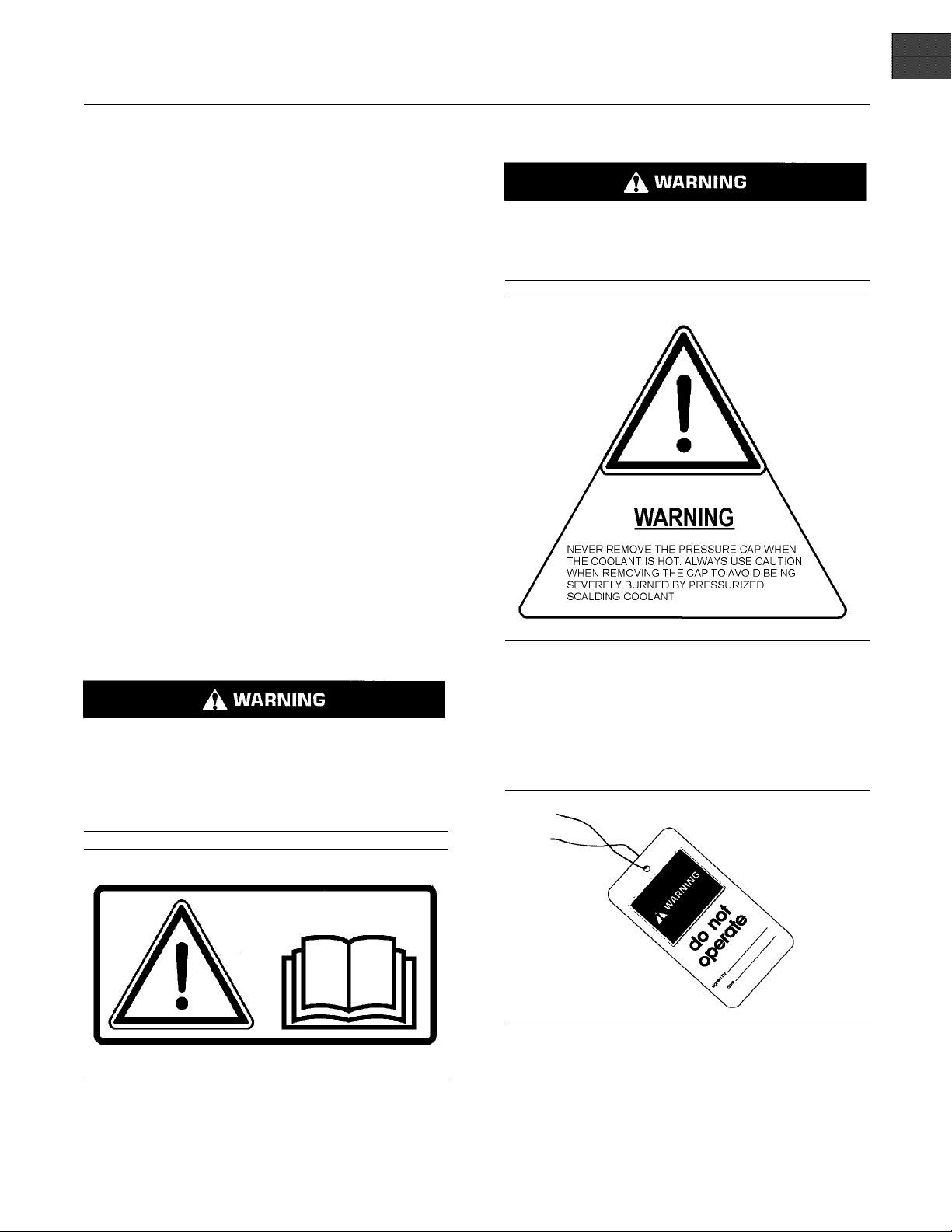
(2) Hot Coolant
Pressurized system: Hot coolant can cause serious burn. To open cap, stop engine, wait until radiator is cool. Then loose the cap slowly to relieve
the pressure.
(1) Universal Warning
Do not operate or work on this equipment unless
ave read and understand the instructions
you h
and warnings in the Operation and Maintenance
Manuals. Failure to follow the instructions or
the warnings could result in serious injury
heed
or death.
Illustration 1
g01231164
Illustration 2
g01231165
i02328435
General Hazard Information
Illustration 3
Attach a “Do Not Operate” warning tag or a similar
warning tag to the start switch or to the controls
before you service the equipment or before you
repair the equipment.
g00104545
Page 6
6 SEBU8191-01
Safety Section
General Hazard Information
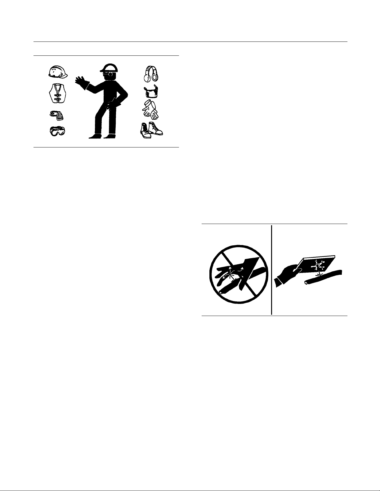
Illustration 4
Wear a hard hat, protective glasses, and other
protective equipment, as required.
Do not wear loose clothing or jewelry that can snag
on controls or on other parts of the engine.
Make sure that all protective guards and all covers
are secured in place on the engine.
Keep the engine free from foreign material. Remove
debris, oil, tools, and other items from the deck, from
walkways, and from steps.
g00702020
When pressuriz
cleaning, wear protective clothing, protective shoes,
and eye protection. Eye protection includes goggles
or a protectiv
The maximum air pressure for cleaning purposes
must be below
water pressure for cleaning purposes must be below
275 kPa (40 psi).
ed air and/or water is used for
efaceshield.
205 kPa (30 psi). The maximum
Fluid Penetration
Pressure can be trapped in the hydraulic circuit long
after the engine has been stopped. The pressure can
cause hydra
escape rapidly if the pressure is not relieved correctly.
Do not remo
until pressure has been relieved or personal injury
may occur. Do not disassemble any hydraulic
componen
or personal injury may occur. Refer to the OEM
information for any procedures that are required to
relieve t
ulic fluid or items such as pipe plugs to
ve any hydraulic components or parts
ts or parts until pressure has been relieved
he hydraulic pressure.
Never put maintenance fluids into glass containers.
Drain all liquids into a suitable container.
Obey all local regulations for the disposal of liquids.
Use all cleaning solutions with care.
Report all necessary repairs.
Do not allow unauthorized personnel on the
equipment.
Ensure that the power supply is disconnected before
you work on the bus bar or the glow plugs.
Perform maintenance on the engine with the
equipment in the servicing position. Refer to the
OEM information for the procedure for placing the
equipment in the servicing position.
Pressure Air and Water
Pressurized air and/or water can cause debris
and/or hot water to be blown out. This could result in
personal injury.
The direct application of pressurized air or
pressurized water to the body could result in personal
injury.
Illustration 5
Always use a board or cardboard when you check
for a leak. Leaking fluid that is under pressure can
penetrate body tissue. Fluid penetration can cause
serious injury and possible death. A pin hole leak can
cause severe injury. If fluid is injected into your skin,
you must get treatment immediately. Seek treatment
from a doctor that is familiar with this type of injury.
g00687600
Containing Fluid Spillage
Care must be taken in order to ensure that fluids
are contained during performance of inspection,
maintenance, testing, adjusting and repair of the
engine. Make provision to collect the fluid with a
suitable container before any compartment is opened
or before any component is disassembled.
Only use the tools that are suitable for collecting
•
fluids and equipment that is suitable for collecting
fluids.
Page 7
SEBU8191-01 7
Safety Section
Burn Prevention
Only use the too
•
fluids and equipment that is suitable for containing
fluids.
Obey all local regulations for the disposal of liquids.
ls that are suitable for containing
i02334785
Burn Prevention
Do not touch any part of an operating engine.
Allow the engine to cool before any maintenance is
performed on the engine.
Contact with high pressure fuel may cause fluid
penetration and burn hazards. High pressure fuel spray may cause a fire hazard. Failure to follow these inspection, maintenance and service instructions may cause personal injury or death.
After the engine has stopped, you must wait for 60
seconds in order to allow the fuel pressure to be
purged from the high pressure fuel lines before any
service or repair is performed on the engine fuel lines.
Oils
Hot oil and hot lubricating components can cause
personal injury. Do not allow hot oil to contact the
skin. Also, do not allow hot components to contact
the skin.
Batteries
Electrolyte is an acid. Electrolyte can cause personal
injury. Do not allow electrolyte to contact the skin or
the eyes. Always wear protective glasses for servicing
batteries. Wash hands after touching the batteries
and connectors. Use of gloves is recommended.
i0232072
Fire Prevention an d Explosion
Preventi
on
1
Allow the pressure to be purged in the air system, in
the hydraulic system, in the lubrication system, or in
the cooling system before any lines, fittings or related
items are disconnected.
Coolant
When the engine is at operating temperature, the
engine coolant is hot. The coolant is also under
pressure. The radiator and all lines to the heaters or
to the engine contain hot coolant.
Any contact with hot coolant or with steam can cause
severe burns. Allow cooling system components to
cool before the cooling system is drained.
Check the coolant level after the engine has stopped
and the engine has been allowed to cool.
Ensure that the filler cap is cool before removing the
filler cap. The filler cap must be cool enough to touch
withabarehand.Removethefiller cap slowly in
order to relieve pressure.
Cooling system conditioner contains alkali. Alkali can
cause personal injury. Do not allow alkali to contact
the skin, the eyes, or the mouth.
stration 6
Illu
All fuels, most lubricants, and some coolant mixtures
ammable.
are fl
Flammable fluids that are leaking or spilled onto hot
faces or onto electrical components can cause
sur
a fire. Fire may cause personal injury and property
damage.
After the emergency stop button is operated ensure
that you allow 15 minutes, before the engine covers
e removed.
ar
Determinewhethertheenginewillbeoperatedinan
vironment that allows combustible gases to be
en
drawn into the air inlet system. These gases could
cause the engine to overspeed. Personal injury,
roperty damage, or engine damage could result.
p
If the application involves the presence of combustible
ases, consult your Perkins dealer and/or your
g
Perkins distributor for additional information about
suitable protection devices.
g00704000
Page 8
8 SEBU8191-01
Safety Section
Fire Prevention and Explosion Prevention
Remove all flamm
able combustible materials or
conductive materials such as fuel, oil, and debris from
the engine. Do not allow any flammable combustible
materials or c
onductive materials to accumulate on
the engine.
Store fuels a
nd lubricants in correctly marked
containers away from unauthorized persons. Store
oily rags and any flammable materials in protective
containers
. Do not smoke in areas that are used for
storing flammable materials.
Do not expos
e the engine to any flame.
Exhaust shields (if equipped) protect hot exhaust
component
s from oil or fuel spray in case of a line,
a tube, or a seal failure. Exhaust shields must be
installed correctly.
Do not weld on lines or tanks that contain flammable
fluids. Do not flame cut lines or tanks that contain
flammable
fluid. Clean any such lines or tanks
thoroughly with a nonflammable solvent prior to
welding or flame cutting.
Wiring must be kept in good condition. All electrical
wires must be correctly routed and securely attached.
Check al
l electrical wires daily. Repair any wires
that are loose or frayed before you operate the
engine. Clean all electrical connections and tighten
all elec
trical connections.
Oil filters and f
uel filters must be correctly installed.
The filter housings must be tightened to the correct
torque. Refer to the Disassembly and Assembly
manual for mor
Illustration 7
e information.
g00704059
Use caution when you are refueling an engine. Do
not smoke while you are refueling an engine. Do not
refuel an engine near open flames or sparks. Always
stop the engine before refueling.
Eliminate all wiring that is unattached or unnecessary.
Do not u
se any wires or cables that are smaller than
the recommended gauge. Do not bypass any fuses
and/or circuit breakers.
Arcing or sparking could cause a fire. Secure
connections, recommended wiring, and correctly
ained battery cables will help to prevent arcing
maint
or sparking.
Contact with high pressure fuel may cause fluid
tration and burn hazards. High pressure fu-
pene
el spray may cause a fire hazard. Failure to follow these inspection, maintenance and service in-
uctions may cause personal injury or death.
str
After the engine has stopped, you must wait for 60
conds in order to allow the fuel pressure to be
se
purged from the high pressure fuel lines before any
service or repair is performed on the engine fuel lines.
Ensure that the engine is stopped. Inspect all lines
and hoses for wear or for deterioration. The hoses
ust be correctly routed. The lines and hoses must
m
have adequate support and secure clamps.
Illustration 8
g00704135
Gases from a battery can explode. Keep any open
flames or sparks away from the top of a battery. Do
not smoke in battery charging areas.
Never check the battery charge by placing a metal
object across the terminal posts. Use a voltmeter or
ahydrometer.
Page 9

SEBU8191-01 9
Safety Section
Crushing Prevention and Cutting Prevention
Incorrect jump
an explosion that can result in injury. Refer to
the Operation Section of this manual for specific
instructions
Do not charge a frozen battery. This may cause an
explosion.
The batteries must be kept clean. The covers
(if equippe
recommended cables, connections, and battery box
covers when the engine is operated.
er cable connections can cause
.
d) must be kept on the cells. Use the
Fire Extinguisher
Make sure that a fire extinguisher is available. Be
familiar with the operation of the fire extinguisher.
Inspect th
extinguisher regularly. Obey the recommendations
on the instruction plate.
e fire extinguisher and service the fire
Lines, Tubes and Hoses
Do not bend high pressure lines. Do not strike high
pressure lines. Do not install any lines that are
damaged
Leaks can cause fires. Consult your Perkins dealer
or your P
Replace the parts if any of the following conditions
are pre
.
erkins distributor for replacement parts.
sent:
i02143194
Crushing Prevention and
Cutting Preve
Support the component correctly when work beneath
the component is performed.
Unless other maintenance instructions are provided,
never attempt adjustments while the engine is
running.
Stay clear of all rotating parts and of all moving
parts. Lea
is performed. After the maintenance is performed,
reinstall the guards.
Keep objects away from moving fan blades. The fan
blades will throw objects or cut objects.
When objects are struck, wear protective glasses in
order to avoid injury to the eyes.
Chips or other debris may fly off objects when objects
are struck. Before objects are struck, ensure that no
one will
ve the guards in place until maintenance
be injured by flying debris.
ntion
i02235492
Mounting and Dismounting
High pressure fuel line or lines are removed.
•
End fittings are damaged or leaking.
•
coverings are chafed or cut.
Outer
•
Wires are exposed.
•
Outer coverings are ballooning.
•
ible part of the hoses are kinked.
Flex
•
Outer covers have embedded armoring.
•
End fittings are displaced.
•
e sure that all clamps, guards, and heat shields
Mak
are installed correctly. During engine operation, this
will help to prevent vibration, rubbing against other
ts, and excessive heat.
par
Inspect the steps, the handholds, and the work area
before mounting the engine. Keep these items clean
and keep these items in good repair.
Mount the engine and dismount the engine only at
locations that have steps and/or handholds. Do not
climb on the engine, and do not jump off the engine.
Face the engine in order to mount the engine or
dismount the engine. Maintain a three-point contact
with the steps and handholds. Use two feet and one
hand or use one foot and two hands. Do not use any
controls as handholds.
Do not stand on components which cannot support
your weight. Use an adequate ladder or use a work
platform. Secure the climbing equipment so that the
equipment will not move.
Do not carry tools or supplies when you mount the
engine or when you dismount the engine. Use a hand
line to raise and lower tools or supplies.
Page 10

10 SEBU8191-01
Safety Section
Before Starting Engine
i02813489
Before Starting Engine
Before the ini
serviced or repaired, make provision to shut the
engine off, in order to stop an overspeed. This may
be accomplis
supply to the engine.
Overspeed s
engines that are controlled electronically. If automatic
shutdown does not occur, press the emergency stop
buttonino
Inspect the engine for potential hazards.
Before starting the engine, ensure that no one is on,
underneath, or close to the engine. Ensure that the
area is fr
If equipped, ensure that the lighting system for the
engine is
lights work correctly, if equipped.
tial start-up of an engine that is new,
hed by shutting off the air and/or fuel
hutdown should occur automatically for
rder to cut the fuel and/or air to the engine.
ee of personnel.
suitable for the conditions. Ensure that all
All protective
be installed if the engine must be started in order
to perform service procedures. T o help prevent an
accident that
around the parts carefully.
Always start
that is described in the Operation and Maintenance
Manual, “Engine Starting” topic in the Operation
Section. Kn
prevent major damage to the engine components.
Knowing the procedure will also help to prevent
personal in
To ensure that the jacket water heater (if equipped)
is working
gauge (if equipped) and/or the oil temperature gauge
(if equipped) during the heater operation.
Note: Do not use Lube oil heaters.
Engine ex
which can be harmful to your health. Always start the
engine and operate the engine in a well ventilated
area. If t
vent the engine exhaust to the outside.
guards and all protective covers must
is caused by parts in rotation, work
theengineaccordingtotheprocedure
owing the correct procedure will help to
jury.
correctly, check the water temperature
haust contains products of combustion
he engine is started in an enclosed area,
All prot
be installed if the engine must be started in order
to perform service procedures. To help prevent an
acciden
around the parts carefully.
Do not b
disable the automatic shutoff circuits. The circuits are
provided in order to help prevent personal injury. The
circu
engine damage.
See th
adjustments.
ective guards and all protective covers must
t that is caused by parts in rotation, work
ypass the automatic shutoff circuits. Do not
its are also provided in order to help prevent
e Service Manual for repairs and for
i02414669
Engine Starting
Do not use aerosol types of starting aids such as
ether. Such use could result in an explosion and
personal injury.
i02414676
Engine St opp ing
Stop the engine according to the procedure in
the Operation and Maintenance Manual, “Engine
Stopping” in order to avoid overheating of the engine
and accelerated wear of the engine components.
Use the Emergency Stop Button ONLY in an
emergency situation. Do not use the Emergency
Stop Button for normal engine stopping. After an
emergency stop, DO NOT start the engine until the
problem that caused the emergency stop has been
corrected.
Stop the engine if an overspeed condition occurs
during the initial start-up of a new engine or an
engine that has been overhauled. In the event of
an overspeed condition, the air shutoff valves will
operate. After operation, the air shutoff valves must
be manually reset.
If a warning tag is attached to the engine start switch
or to the controls DO NOT start the engine or move
the controls. Consult with the person that attached
the warning tag before the engine is started.
Page 11

SEBU8191-01 11
Safety Section
Electrical System
i02414678
Electrical System
Never disconn
circuit cable from the battery when the charging unit
is operating. A spark can cause the combustible
gases that ar
To help prevent sparks from igniting combustible
gases that a
negative “−” cable should be connected last from the
external power source to the negative “−” terminal of
the starti
Check the electrical wires daily for wires that
arelooseo
connections before the engine is started. Repair all
frayed electrical wires before the engine is started.
See the Op
specific starting instructions.
Engines t
ground straps can be damaged by electrical
discharge.
ect any charging unit circuit or battery
e produced by some batteries to ignite.
re produced by some batteries, the
ng motor.
r frayed. Tighten all loose electrical
eration and Maintenance Manual for
hat are installed without engine-to-frame
Setpoint adjus
•
Sensors
•
Wiring Harness
•
ters (if equipped)
System Description
The system is
(ECU). The ECU contains a microprocessor that has
an Electronic Programmable Read Only Memory
(EPROM). Th
are stored in the EPROM. The actuator is connected
to the fuel injectors via a mechanical linkage.
A laptop computer is used to set the operating
parameters of the governor. The laptop computer is
connected
operating parameters for the governor should only be
modified by a trained Perkins representative. Refer to
the Speci
for more information.
controlled by an Electronic control Unit
e operating parameters for the governor
to the governor via an interface cable. The
al Instruction, “Pandoras Digital Governor”
To ensure that the engine and the engine electrical
systems function correctly, an engine-to-frame
ground s
used. This path may be provided by way of a direct
engine ground to the frame.
The connections for the grounds should be tight and
free of corrosion. The engine alternator must be
groun
a wire that is adequate to handle the full charging
current of the alternator.
trap with a direct path to the battery must be
ded to the negative “-” battery terminal with
i0241
4684
Engine Electronics
Tampering with the electronic system installation
or the OEM wiring installation can be dangerous
and could result in personal injury or death and/or
engine damage.
The engine is controlled by a digital Pandoras
governor. The control system includes the following
components.
Control unit
•
Actuator
•
Page 12
12 SEBU8191-01
Product Information Section
General Information
Product Information
Section
General Infor mation
i02640420
Welding on Engines with
Electronic Controls
NOTICE
Proper welding procedures are necessary in order
to avoid damage to the engine's ECM, sensors, and
associated components. When possible, remove the
component from the unit and then weld the component. If removal of the component is not possible,
the following procedure must be followed when you
weld with a unit that is equipped with an Electronic
Engine. The following procedure is considered to be
the safest procedure to weld a component. This procedure should provide a minimum risk of damage to
electronic components.
NOTICE
Do not ground the welder to electrical components
such as the ECM or sensors. Improper grounding can
cause damage to the drive train bearings, hydraulic
components, electrical components, and other components.
Clamp the ground cable from the welder to the component that will be welded. Place the clamp as close
as possible to the weld. This will help reduce the possibility of damage.
1. Stop the engine. Turn the switched power to the
OFF position.
2. Disconnect the negative battery cable from the
battery. If a battery disconnect switch is provided,
open the switch.
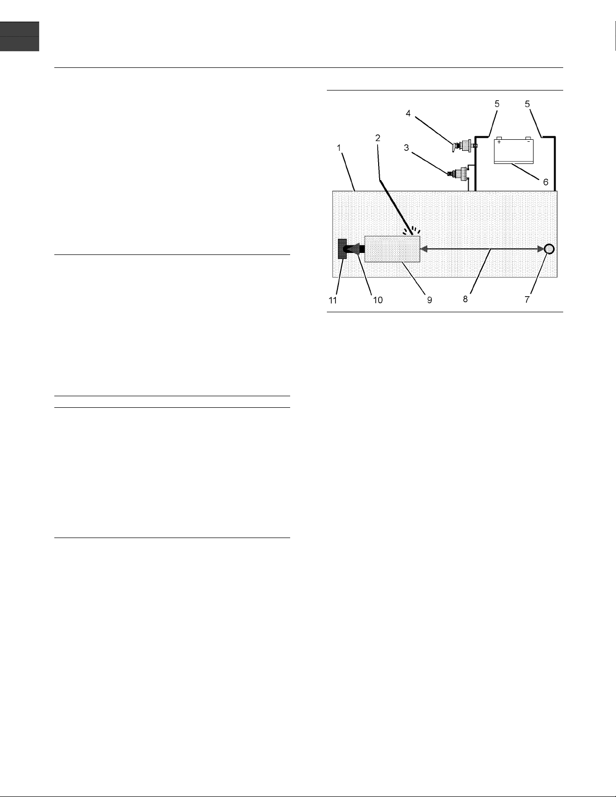
Illustration 9
Use the example above. The current flow from the welder to
the ground clamp of the welder will not cause damage to any
associated components.
(1) Engine
(2) Welding rod
(3) Keyswitch in the OFF position
(4) Battery disconnect switch in the open position
(5) Disconnected battery cables
(6) Battery
(7) Electrical/Electronic component
(8) Maximum distance between the c ompo nent that is being
welded and any electrical/electronic component
(9) The component that is being welded
(10) Cur rent path of the welder
(11) Ground clamp for the welder
4. Connect the welding ground cable directly to the
part that will be welded. Place the ground cable as
close as possible to the weld in order to reduce the
possibility of welding current damage to bearings,
hydraulic components, electrical components, and
ground straps.
Note: If electrical/electronic components are used
as a ground for the welder, or electrical/electronic
components are located between the welder ground
and the weld, current flow from the welder could
severely damage the component.
g01324562
3. Disconnect the connectors from the ECM.
5. Protect the wiring harness from welding debris
and spatter.
6. Use standard welding practices to weld the
materials.
Page 13

SEBU8191-01 13
Product Information Section
Model Views
Model Views
i03754026
Model View Illustrations
4012-46A
The following model views show typical features of
the engine.
may appear different from the Illustrations.
Due to individual applications, engines
Note: Only
the following Illustrations.
serviced components are identified on
Page 14
14 SEBU8191-01
Product Information Section
Model Views
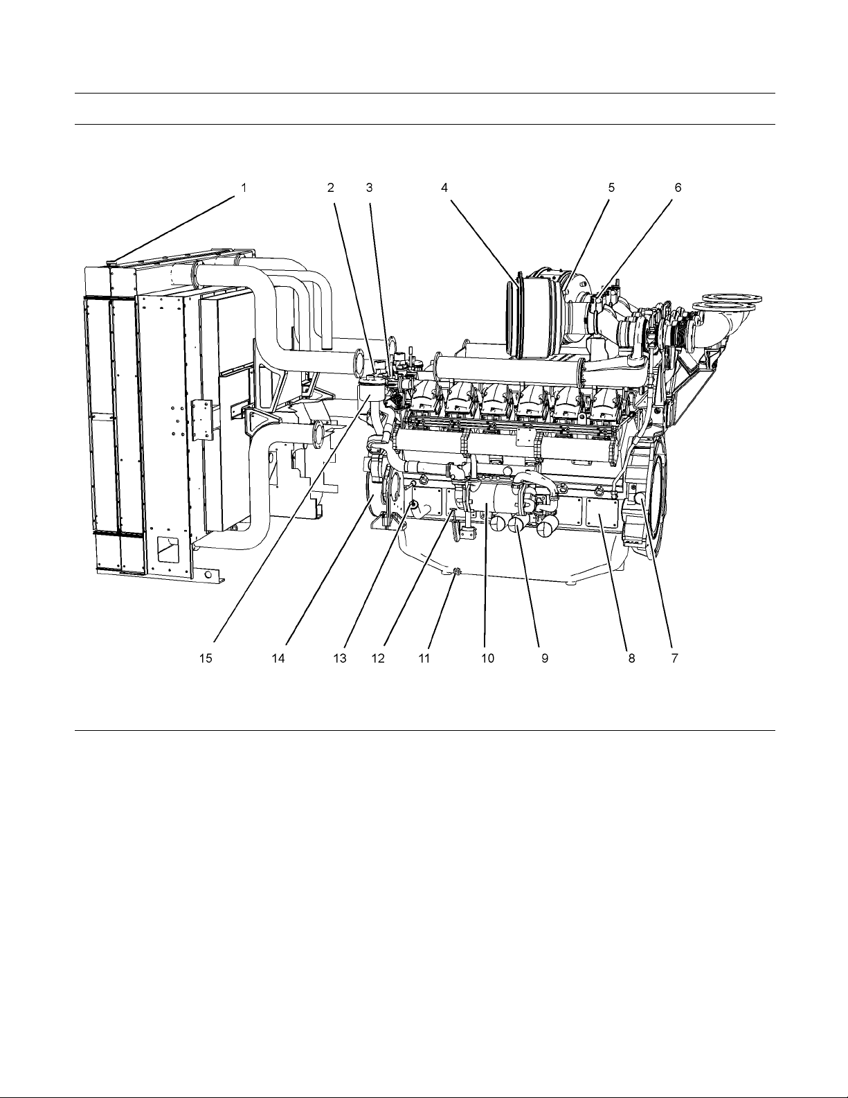
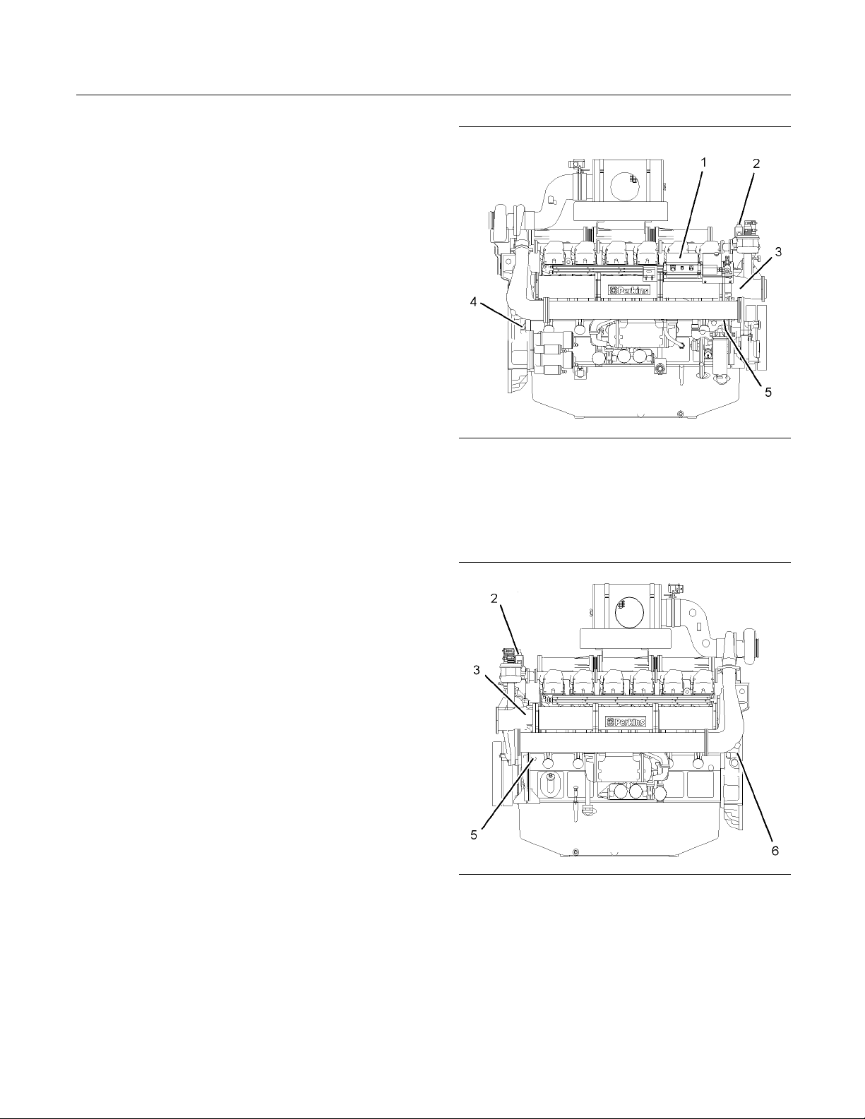
Illustration 10
Typical example
Left side view of engine
(1) Radiator cap
(2) Thermostat housing
(3) C oolant temperature switch
(4) Air cleaner
(5) Res triction indicator for air cleaner
(6) Air shutoff valve
(7) Timing inspection hole
(8) Inspection covers for crankcase
(9) 3x Oil filters
(10) Oil cooler
g02090055
(11) Oil drain plug
(12) O il level gauge
(13) Oil fi ller
(14) Crankshaft damper
(15) Engine crankcase breather
Page 15
SEBU8191-01 15
Product Information Section
Model Views
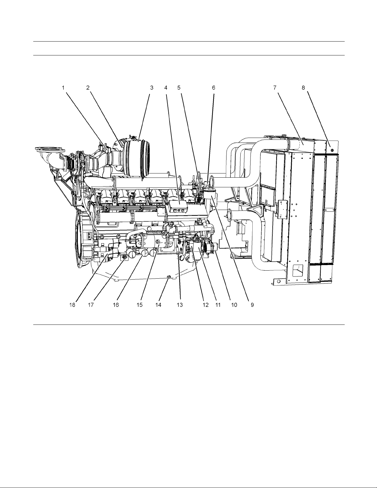
Illustration 11
Typical example
Right side view of engine
(1) Air shutoff valve
(2) Res triction indicator for air cleaner
(3) Air cleaner
(4) Electronic governor control unit
(5) C oolant temperature switch
(6) Thermostat housing
(7) Aftercooler
(8) Radiator
(9) Engine crankcase breather
(10) Alternator
(11) Primary fuel filter/water separator
(12) Oil pump
i03754051
Engine De script ion
The 4012-46A Engine model is designed for power
generation. The engine is available with turbocharged
aftercooled aspiration.
g02090056
(13) Fuel priming pump
(14) Oil pan drain plug
(15) Oil cooler
(16) 3x Oil filters
(17) Starter relay
(18) 2x Starting motors
Engine Specifications
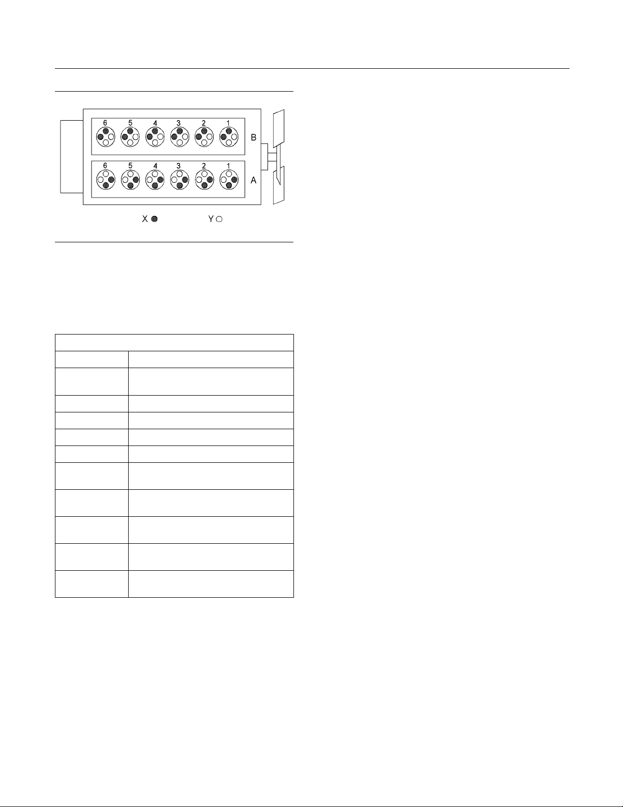
te: The number 1 cylinders are to the front. The
No
front of the engine is farthest from the flywheel.
Bank A cylinders are on the right-hand side of the
ngine. Bank B cylinders are on the left-hand side of
e
the engine. To determine the left and right sides of
the engine, stand behind the flywheel and face the
ampers.
d
Page 16
16 SEBU8191-01
Product Information Section
Model Views
Illustration 12
4012-46A Engine model
(A) Bank
(B) Bank
(X) Inlet valves
(Y) Exhaust valves
Table 1
4012-46A Engine Specifications
Cycle 4 Stroke
Number of
Cylinders
Configuration Vee-form
Bore 160 mm (6.299 inch)
e
Strok
Displacement
Compression
Ratio
Rotation
(flywheel end)
Firing Order
Inlet Valve Lash
(Cold)
Exhaust Valve
Lash (Cold)
190 mm
45.84 L (2797.328 in
Counterclockwise
1A-6B-5A-2B-3A-4B-6A-1B-2A-
0.40 mm (0.016 inch)
0.40 mm (0.016 inch)
12
(7.480 inch)
13:1
5B-4A-3B
g01210840
3
)
The engine lubr
icating oil is supplied by a gear-driven
pump. The lubrication oil is cooled and filtered.
Bypass valves provide unrestricted flow of lubrication
oil to the engi
nepartswhenoilviscosityishigh.
Bypass valves can also provide unrestricted flow
of lubrication oil to the engine parts if the oil filter
element shou
ld become plugged.
Engine efficiency, efficiency of emission controls, and
engine perf
ormance depend on adherence to proper
operation and maintenance recommendations.
Engine performance and efficiency also depend on
the use of re
commended fuels, lubrication oils, and
coolants. Refer to this Operation and Maintenance
Manual, “Maintenance Interval Schedule” for more
informati
on on maintenance items.
Engine Cooling and Lubrication
The cooling system consists of the following
components:
Gear-driven water pumps
•
Water temperature regulators which regulate the
•
engine coolant temperature
Gear-driven oil pump (gear type)
•
Oil coolers
•
Page 17
SEBU8191-01 17
Product Information Section
Product Identification Information
Product Identification
Information
i03754093
Plate Locations and Film
Locations
Engine Identification
Perkins engines are identified by an engine serial
number.
A typical example of an engine serial number is
DGB M**** U00001V.
D
_________________________________________ Made in Stafford
____________________________________ Application (Table 2)
G
________________________________ Type of engine (Table 3)
B
________________________ Number of cylinders (Table 4)
M
__________________________________Fixed build number
*****
____________________________ Built in the United Kingdom
U
Table 3
F TG
L
A
B
D
M
K
N
P
R
S TEG3
W TRW2
X TRW3
Table 4
F 6
H 8
M 12
R 16
Type of engine (Diesel)
TAG
TAG1
TAG2
TAG3
TWG
TWG2
TWG3
TRG1
TEG2
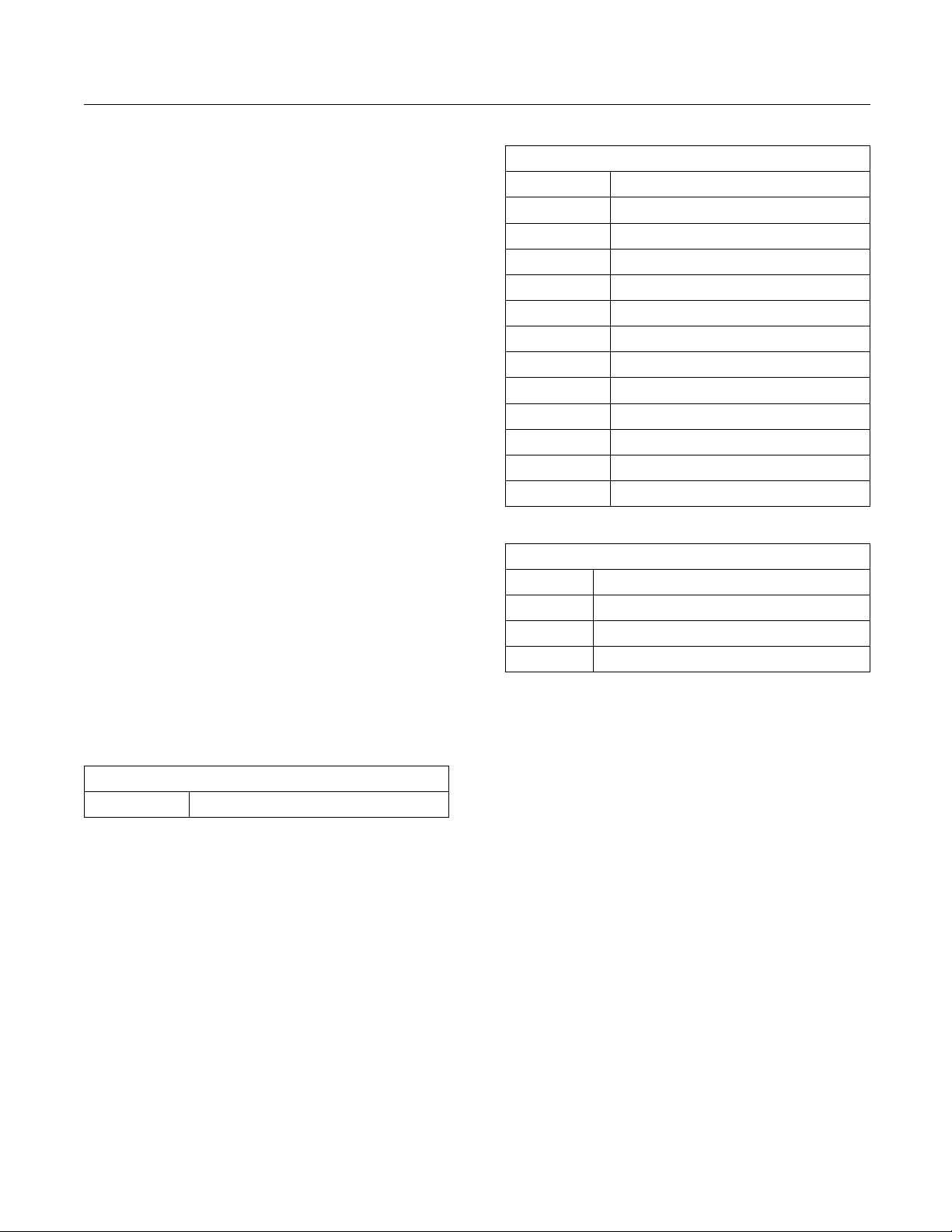
Number of Cylinders
00001
V
Table 2
____________________________________Engine Number
_____________________________________ Year of Manufacture
Application
G Genset
Perkins dealers and Perkins distributors require all of
these numbers in order to determine the components
that were included in the engine. This permits
accurate identification of replacement part numbers.
Page 18
18 SEBU8191-01
Product Information Section
Product Identification Information
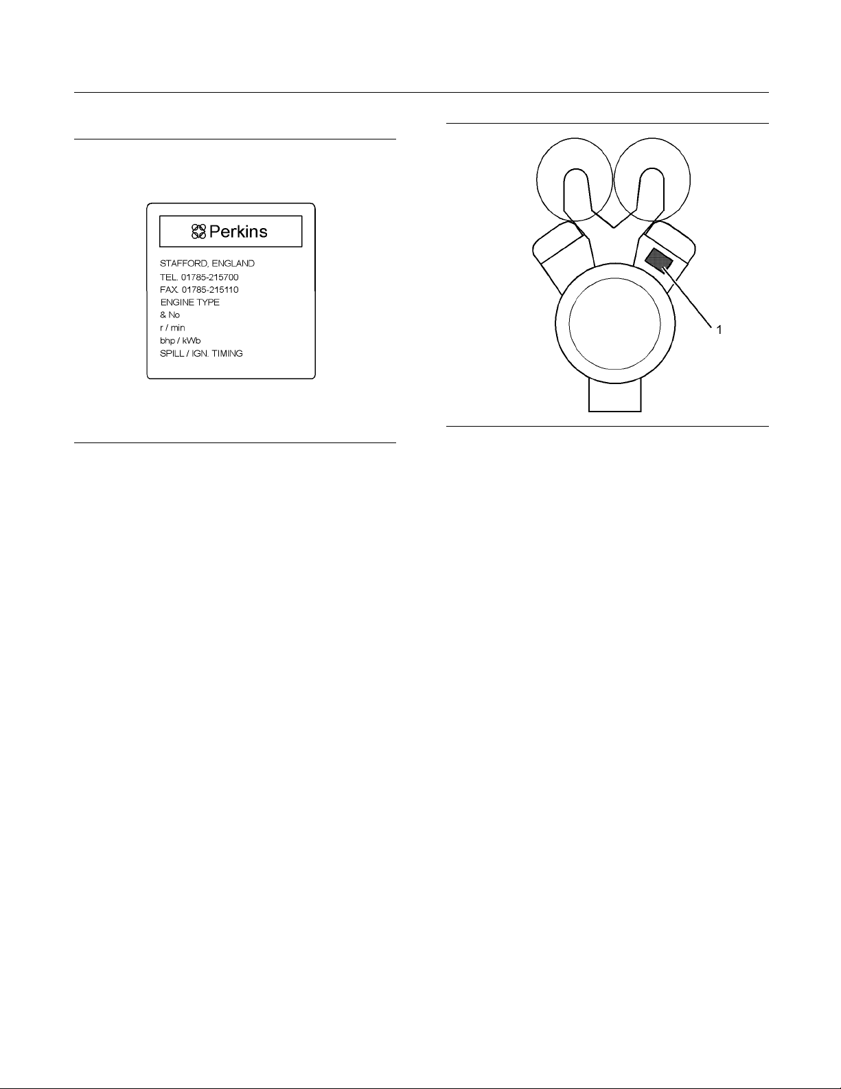
Serial Number Plate
Illustration 13
Serial number plate
The engine serial number plate contains the following
information:
Place of manufacture
•
Telephone number of manufacturer
•
Fax number of manufacturer
•
Type of engine
•
Engine serial number
•
Rated speed
•
Power output
•
Engine timing
•
Rating
•
g01266904
Illustration 14
The location of the serial number plate for vee-form engines
The serial number plate (1) on a vee-form engine is
located on the rear face of the cylinder block (bank
A). See Illustration 14.
g01229580
Page 19
SEBU8191-01 19
Operation Section
Lifting and Storage
Operation Section
Lifting and Storage
i02414727
Engine Lifting
NOTICE
Never bend the eyebolts and the brackets. Only load
the eyebolts and the brackets under tension. Remember that the capacity of an eyebolt is less as the angle
between the supporting members and the object becomes less than 90 degrees.
When it is necessary to remove a component at an
angle, only use a link bracket that is properly rated for
the weight.
To re m ov e t he e n
that are on the engine. If necessary, remove engine
components in order to avoid damage from the lifting
device.
Lifting eyes are designed and installed for specific
engine arran
and/or the engine make the lifting eyes and the lifting
fixtures obsolete. If alterations are made, ensure
that correc
your Perkins dealer or your Perkins distributor for
information regarding fixtures for correct engine
lifting.
t lifting devices are provided. Consult
gine ONLY, use the lifting eyes
gements. Alterations to the lifting eyes
i03781209
Engine Storage
Refer to Perkins Engine Company Limited, Stafford,
ST16 3UB for information on engine storage.
There are three different levels of engine storage.
Level “A, B and C”.
lustration 15
Il
Level “A ”
Level “A” will give protection for 12 months for diesel
engines and for gas engines. This level is used for
engines that are transported in a container or by a
truck.
Level “B ”
This level is additional to level “A”. Level “B ” will
give protection under normal conditions of storage
from −15° to +55°C (5° to 99°F) and “90%” relative
humidity, for a maximum of 2 year.
Level “C ”
This level is additional to level “B”. Level “C” will
give protection for five years in tropical or in arctic
climates. Level “C” also meets MOD NES 724
Level “J” for Europe, when engines are stored in an
unheated building or in the open under a waterproof
cover.
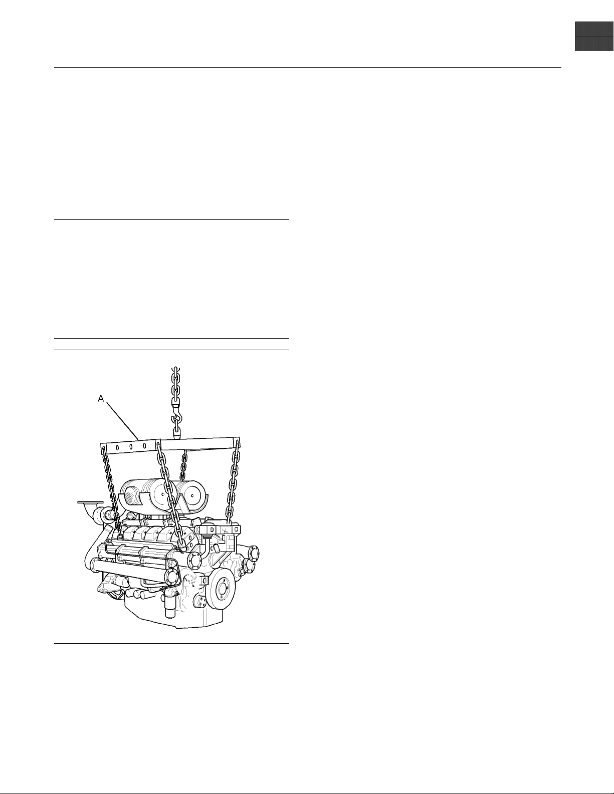
g01230422
Use a hoist to remove heavy components. Use a
ifting beam (A) to lift the engine. All supporting
l
members (chains and cables) should be parallel
to each other. The chains and cables should be
erpendicular to the top of the object that is being
p
lifted.
Page 20
20 SEBU8191-01
Operation Section
Features and Controls
Features and Controls
i02415217
Monitoring System
The engine is equipped with sensors or switches to
monitor the following parameters:
Coolant temperature (Switch)
•
Oil pressure (Switch)
•
Intake manifold boost pressure (Sensor)
•
Exhaust temperature (if equipped)
•
Engine speed (Sensor)
•
Engine overspeed (Sensor or Switch)
•
Sensors and Electrical
Components
i02415219
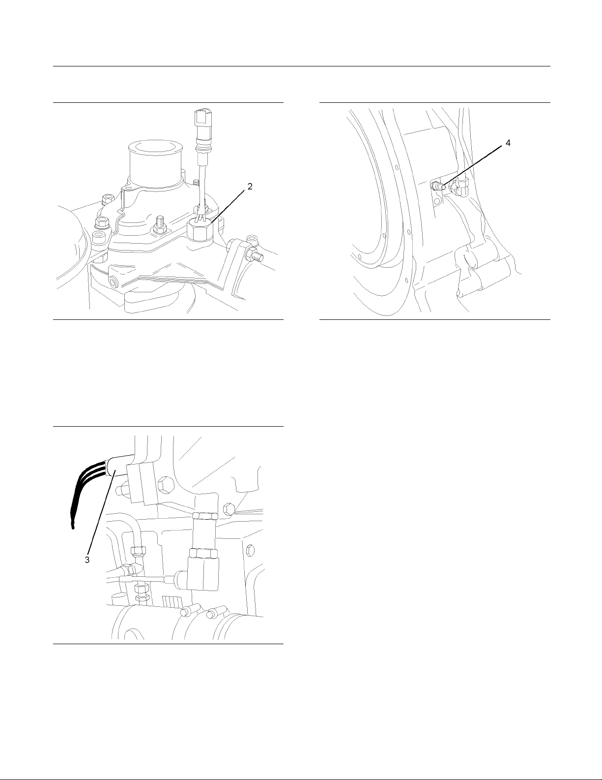
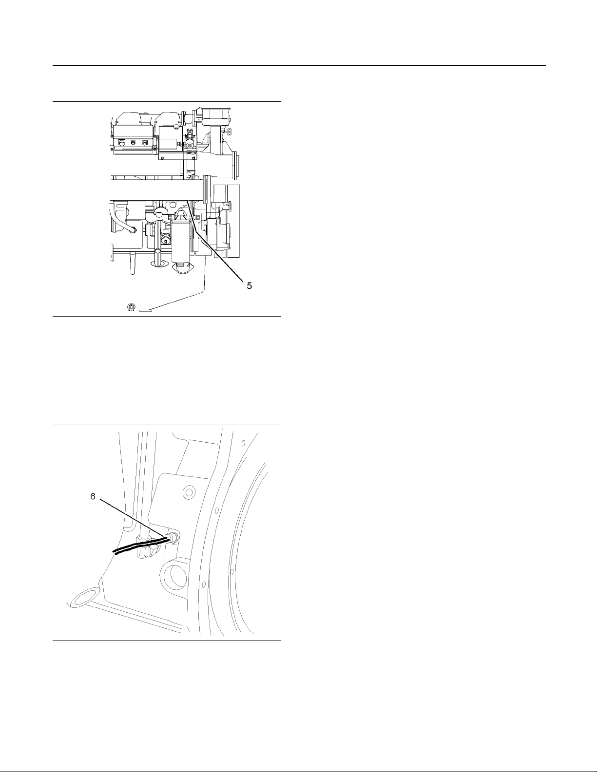
Illustration 16
Right side view of engine
(1) Electronic control unit (ECU)
(2) C oolant temperature switch
(3) B oost pressure sensor
(4) Speed sensor
(5) Oil pressure switch
g01231519
Sensor Locations
trations 16 and 17 show the typical locations
Illus
of the sensors on the engine. Specific engines
may appear different from the illustrations due to
erences in applications. Illustration 16 shows the
diff
location of the Electronic Control Unit (ECU).
Illustration 17
Left side view of engine
) Coolant temperature switch
(2
) Boost pressure sensor
(3
) Oil pressure switch
(5
) Overspeed sensor
(6
g01
231520
Page 21
SEBU8191-01 21
Operation Section
Features and Controls
Coolant Temperature Switches
Illustration 18
Coolant temperature switch
The coolant temperature switches (2) monitor the
engine coolant temperature. The switches are
supplied for connecting to an OEM supplied panel.
g01231514
Boost Pressure Sensors
Speed Sensor
Illustration 20
Speed sensor
The speed sensor (4) should be serviced at
the required maintenance interval. Refer to the
Operation and Maintenance Manual, “Speed Sensor,
Clean/Inspect”.
Failure of the Speed Sensor
g01231517
Illustration 19
Boost pressure sensor
g01231515
The boost pressure sensor (3) measures the
pressure in the inlet air manifold. A signal is sent to
the ECU (1).
If the ECU (1) does not receive a signal from the
speed sensor (4), the engine cannot run.
If the ECU does not receive a signal from the speed
sensor (4), the engine will shut down. A faulty speed
sensor should be replaced.
Note: Intermittent failure of the speed sensor will
cause the engine to run erratically. This may also
cause overspeed.
Page 22
22 SEBU8191-01
Operation Section
Features and Controls
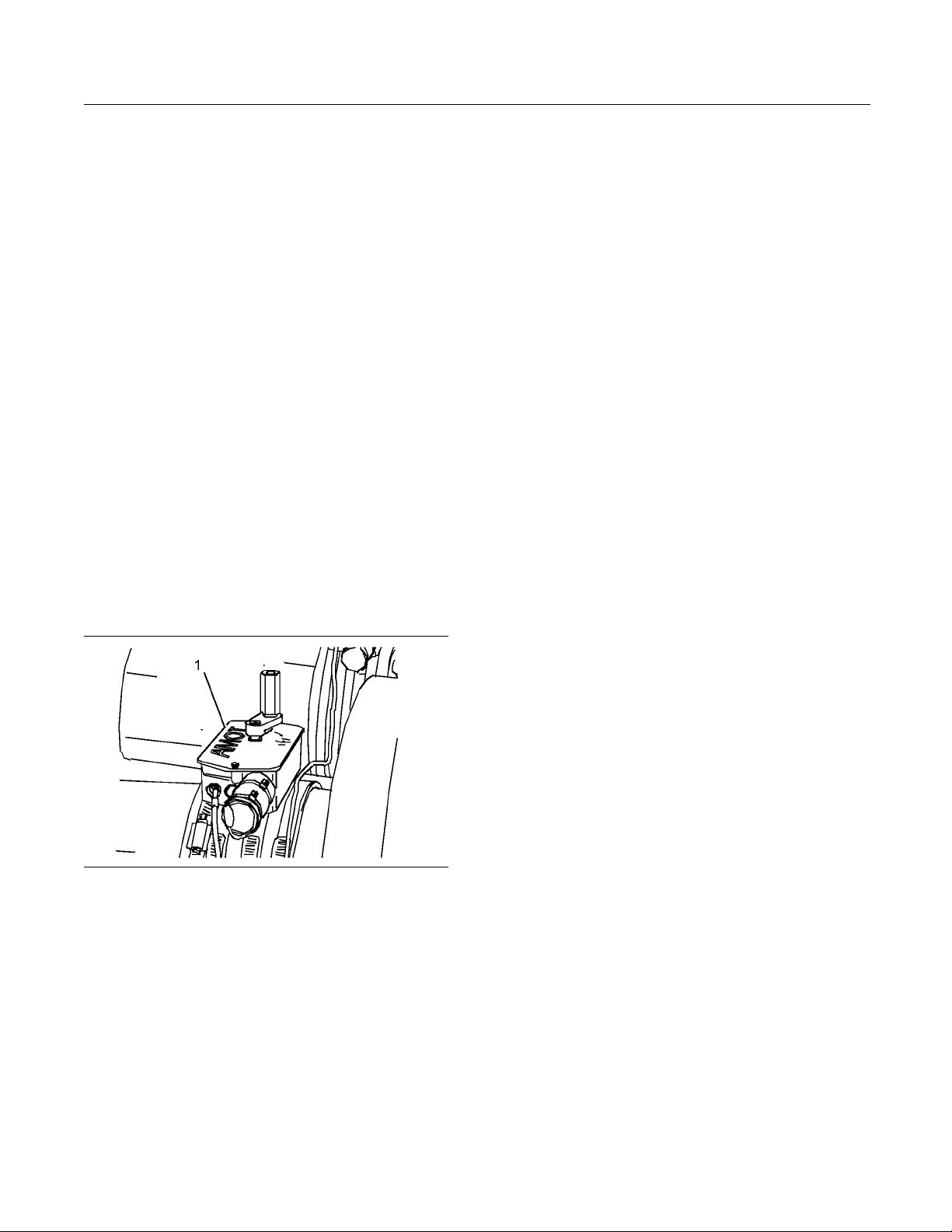
Engine Oil Pressure Switch
Illustration 21
Engine oil pressure switch
g01278615
The engine oil pressure switch (5) is mounted in the
main oil gallery. The engine oil pressure switches are
supplied for connecting to an OEM supplied panel (1).
Overspeed Sensor
Illustration 22
Overspeed sensor
g01231518
The signal from the overspeed sensor (6) is
connected to the overspeed switch or the overspeed
circuit in the OEM supplied panel.
Page 23
SEBU8191-01 23
Operation Section
Engine Starting
Engine Starting
i02415220
Before Starting Engine
Before the e
daily maintenance and any other periodic
maintenance that is due. Refer to the Operation
and Mainte
Schedule” for more information.
Note: Do no
controls if there is a “DO NOT OPERATE” warning
tag or similar warning tag attached to the start switch
or to the c
1. Open the fuel supply valve (if equipped).
2. If the engine has not been started for several
weeks, fuel may have drained from the fuel
system.
some air pockets will be trapped in the engine.
In these instances, prime the fuel system. Refer
to the O
System-Prime”formoreinformation.
ngine is started, perform the required
nance Manual, “Maintenance Interval
t start the engine or move any of the
ontrols.
Also, when fuel filters have been changed,
peration and Maintenance Manual, “Fuel
b. Turn the keyswi
Hold the keyswitch in this position until
the oil pressure gauge indicates 100 kPa
(14.5040 psi)
in the START position for an additional 10
seconds.
Note: The keyswitch is part of the OEM supplied
panel. The exact procedure for starting may vary.
Refer to OEM
starting procedure.
c. Turn the key
d. Reconnect the speed pickup connector.
The engine is now ready to run.
supplied instructions for the correct
tch to the START position.
. Continue to hold the keyswitch
switch to the STOP position.
i02415221
Starting the Eng ine
Normal Engine Starting Procedure
Note: When possible, ensure that the engine is not
started under load.
Illustration 23
3. Ensure that the two air shutoff valves (1) are in
the OPEN position.
4. If the engine has not been started for more than
three months, the engine oil system must be
primed. Follow Steps 4.a through 4.d in order to
prime the engine oil system.
a. Ensure that the governor stays in the STOP
position by disconnecting the speed pickup
connector on the governor control.
g01230837
1. Turn the keyswitch to the START position. The
engine should start immediately.
2. Allow the keyswitch to return to the RUN position
after the engine starts.
If the engine does not start after 10 seconds,
return the keyswitch in the RUN position for 10
seconds. Then repeat Steps 1 and 2.
Note: If the engine fails to start after three attempts,
investigate the cause.
3. After the engine has started follow Steps 3.a
through 3.d.
a. Check the oil pressure.
b. Inspect the engine for leaks.
c. Ensure that the batteries for the engine are
receiving a charge.
d. After the engine has run for five minutes, check
the engine monitoring systems. Ensure that the
engine is operating correctly before the load
is applied.
Page 24

24 SEBU8191-01
Operation Section
Engine Starting
i02415223
Cold Weather Starting
Do not use aerosol types of starting aids such as
ether. Such use could result in an explosion and
personal injury.
Startability will be improved at temperatures below
+10 °C (+50 °F) from the use of a jacket water heater
or extra battery capacity.
Page 25

SEBU8191-01 25
Operation Section
Engine Operation
Engine Operation
i02415225
Engine Operation
Correct ope
in obtaining the maximum life and economy of
the engine. If the directions in the Operation and
Maintenan
minimized and engine service life can be maximized.
Gauge read
and the data should be recorded frequently while
the engine is operating. Comparing the data over
time will
gauge.Comparingdataovertimewillalsohelp
detect abnormal operating developments. Significant
changes
ration and maintenance are key factors
ce Manual are followed, costs can be
ings (if equipped) should be observed
help to determine normal readings for each
in the readings should be investigated.
i02415226
Fuel Conservation Prac tices
The efficiency
economy. Perkins design and technology in
manufacturing provides maximum fuel efficiency in
all applicat
in order to attain optimum performance for the life
of the engine.
Avoid spilling fuel. Fuel expands when the fuel is
•
warmed up. The fuel may overflow from the fuel
tank. Insp
lines, as needed.
Be aware of
•
Use only the recommended fuels.
Avoid unn
•
engine is not under load, the engine should be
shut down.
Observe the air cleaner service indicator frequently.
•
The air cleaner elements should be replaced when
the air c
of the engine can affect the fuel
ions. Follow the recommended procedures
ect fuel lines for leaks. Repair the fuel
the properties of the different fuels.
ecessary running at a low load. If the
leaner elements are dirty.
Maintain the electrical systems. One damaged
•
battery
consume excess power and excess fuel.
Ensure
•
The drive belts should be in good condition.
Ensur
•
tight. The connections should not leak.
Ensur
•
working order.
Cold
•
from the jacket water system and the exhaust
system, when possible. Keep cooling system
comp
components in good repair. Never operate the
engine without water temperature regulators.
All
temperatures.
cell will overwork the alternator. This will
that the drive belts are correctly adjusted.
e that all of the connections of the hoses are
e that the driven equipment is in good
engines consume excess fuel. Utilize heat
onents clean and keep cooling system
of these items will help maintain operating
Page 26

26 SEBU8191-01
Operation Section
Engine Stopping
Engine Stopping
i02415227
Stopping the Engine
Note: Indiv
control systems. Ensure that the shutoff procedures
are understood. Use the following general guidelines
in order to
1. Remove the load from the engine. Allow the
engine to r
cool the engine.
2. Stop the e
according to the shutoff system on the engine and
turn the ignition key switch to the OFF position.
If neces
provided by the OEM.
Emergency Stopping
Emergency shutoff controls are for EMERGENCY use
ONLY. DO NOT use emergency shutoff devices or
contr
idual applications will have different
stop the engine.
un off load for five minutes in order to
ngine after the cool down period
sary, refer to the instructions that are
NOTIC
ols for normal stopping procedure.
E
i02415230
i02415231
After Stopping Engine
Note: Before y
the engine for at least 10 minutes in order to allow
the engine oil to return to the oil pan.
If the engine is equipped with a service hour meter,
•
note the reading. Perform the maintenance that
is in the Ope
“Maintenance Interval Schedule”.
Check the c
•
between the “MIN” mark and the “MAX” mark on
the engine oil level gauge.
If necessary, perform minor adjustments. Repair
•
any leaks from the low pressure fuel system and
from the c
Fill the fuel tank in order to help prevent
•
accumula
the fuel tank.
Only use antifreeze/coolant mixtures recommended in
the Coo
and Maintenance Manual. Failure to do so can cause
engine damage.
ou check the engine oil, do not operate
ration and Maintenance Manual,
rankcase oil level. Maintain the oil level
ooling, lubrication or air systems.
tion of moisture in the fuel. Do not overfill
NOTICE
lant Specifications that are in the Operation
The engine should be equipped with an emergency
button. For more information about the
stop
emergency stop button, refer to the OEM information.
ure that any components for the external system
Ens
that support the engine operation are secured after
the engine is stopped.
In the event of an overspeed condition, the air shutoff
valves will operate. After operation, the air shutoff
lves must be manually reset.
va
Pressurized System: Hot coolant can cause serious burns. To open the cooling system filler cap,
stop the engine and wait until the cooling system
components are cool. Loosen the cooling system
pressure cap slowly in order to relieve the pressure.
Allow the engine to cool. Check the coolant level.
•
Check the coolant for correct antifreeze protection
•
and the correct corrosion protection. Add the
correct coolant/water mixture, if necessary.
Perform all required periodic maintenance on all
•
driven equipment. This maintenance is outlined in
the instructions from the OEM.
Page 27

SEBU8191-01 27
Maintenance Section
Refill Capacities
Maintenance Section
Refill Capacities
i03754130
Refill Capaci ties
Lubrication System
The refill capacities for the engine crankcase
reflect the approximate capacity of the crankcase
or sump plus standard oil fi lters. Auxiliary oil filter
systems will require additional oil. Refer to the OEM
specifications for the capacity of the auxiliary oil filter.
Refer to the Operation and Maintenance Manual,
“Maintenance Section” for more information on
Lubricant Specifications.
Table 5
Engine
Refill Capacities
Compartment or System
Crankcase Oil Sump
(1)
These values are the total capacities for the crankcase oil
sump which includes the standard factory installed oil filters
and oil c oolers. Engines with auxiliary oil filters will require
additional oil. Refer to the OEM specifications for the capacity
of the auxiliary oil filter.
(1)
Cooling System
Refer to the OEM specifications for the External
System capacity. This capacity information will be
ed in order to determine the amount of coolant
need
and antifreeze that is required for the Total Cooling
System.
4012-46A
178 L (39.2 Imp gal)
Table 7
Engine
Refill Capacities
Compartment or System 4012-46A
Minimum Capacity of Fuel
Tan k
14000 L (3000 Imp gal)
i04328169
Fluid Recommendations
General Lubricant Inform a tion
The following lubricant recommendations must be
followed.
Engine Manufacturers Association (EMA)
Oils
The “Engine Manufacturers Association
Recommended Guideline on Diesel Engine Oil” is
recognized by Perkins. For detailed information
about this guideline, see the latest edition of EMA
publication, “EMA DHD -1”.
API Oils
The Engine Oil Licensing and Certification System by
the American Petroleum Institute (API) is recognized
by Perkins. For detailed information about this
system, see the latest edition of the “API publication
No. 1509”. Engine oils that bear the API symbol are
authorized by API.
le 6
Tab
ine
Eng
Refill Capacities
Compartment or System Liters
External System Per OEM
(1)
The External System includes a radiator w ith the following
components: heat exchanger and piping. Refer to the OEM
specifications. Enter the value for the capacity of the External
System in this column.
(1)
Fuel System
Refer to the OEM specifications for additional
information on the capacity of the Fuel System.
0546535
Illustration 24
Typical API symbol
iesel engine oils CC, CD, CD-2, and CE have
D
g0
not been API authorized classifications since 1
January 1996. Table 8 summarizes the status of the
lassifications.
c
Page 28

28 SEBU8191-01
Maintenance Section
Refill Capacities
Table 8
API Classifications
Current Obsolete
CH-4, , CI-4 CE, CC, CD
CD-2
(1)
(1)
The oil CD-2
sell engine
-
is for a two-cycle diesel engine. Perkins does not
s that u tilize CD-2 oil.
Termin olog y
Certain abbreviations follow the nomenclature of
“SAE J754”. Some classifications follow “SAE J183”
abbreviat
ions, and some classifications follow the
“EMA Recommended Guideline on Diesel Engine
Oil”. In addition to Perkins definitions, there are other
definitio
ns that will be of assistance in purchasing
lubricants. Recommended oil viscosities can be found
in this publication, “Fluid Recommendations/Engine
Oil” topi
Engine O
c (Maintenance Section).
il
Commercial Oils
The performance of commercial diesel engine
oils is based on American Petroleum Institute
(API) c
developed in order to provide commercial lubricants
for a broad range of diesel engines that operate at
variou
Only use commercial oils that meet the following
class
•
•
•
lassifications. These API classifications are
s conditions.
ifications:
API CG-4
API CH-4
I-4
API C
DHD-1 oils will
meet the needs of high performance
Perkins diesel engines that are operating in many
applications. The tests and the test limits that are
used to define D
HD-1 are similar to the new API
CH-4 classification. Therefore, these oils will also
meet the requirements for diesel engines that require
low emission
s. DHD-1 oi ls are designed to control the
harmful effects of soot with improved wear resistance
and improved resistance to plugging of the oil filter.
These oils w
ill also provide superior piston deposit
control for engines with either two-piece steel pistons
or aluminum pistons.
All DHD-1 oils must complete a full test program
with the base stock and with the viscosity grade of
the finishe
dcommercialoil.Theuseof“APIBase
Oil Interchange Guidelines” are not appropriate for
DHD-1 oils. This feature reduces the variation in
performan
ce that can occur when base stocks are
changed in commercial oil formulations.
DHD-1 oil
s are recommended for use in extended oil
change interval programs that optimize the life of the
oil. These oil change interval programs are based
on oil ana
lysis. DHD-1 oils are recommended for
conditions that demand a premium oil. Your Perkins
dealer or your Perkins distributor has the specific
nes for optimizing oil change intervals.
guideli
API CH-4 – API CH-4 oils were developed in order to
meet the
requirements of the new high performance
diesel engines. Also, the oil was designed to
meet the requirements of the low emissions diesel
engine
s. API CH-4 oils are also acceptable for use
in older diesel engines and in diesel engines that
use high sulfur diesel fuel. API CH-4 oils may be
n Perkins engines that use API CG-4 and API
used i
CF-4 oils. API CH-4 oils will generally exceed the
performance of API CG-4 oils in the following criteria:
its on pistons, control of oil consumption, wear
depos
of piston rings, valve train wear, viscosity control,
and corrosion.
In order to make the correct choice of a commercial
, refer to the following explanations:
oil
EMA DHD-1 – The Engine Manufacturers
ociation (EMA) has developed lubricant
Ass
recommendations as an alternative to the API oil
classification system. DHD-1 is a Recommended
ideline that defines a level of oil performance for
Gu
these types of diesel engines: high speed, four stroke
cycle, heavy-duty, and light duty. DHD-1 oils may
used in Perkins engines when the following oils
be
are recommended: API CH-4, API CG-4, and API
CF-4. DHD-1 oils are intended to provide superior
rformance in comparison to API CG-4 and API
pe
CF-4.
Three new engine tests were developed for the API
CH-4 oil. The first test specifically evaluates deposits
stons for engines with the two-piece steel piston.
on pi
This test (piston deposit) also measures the control
of oil consumption. A second test is conducted
h moderate oil soot. The second test measures
wit
the following criteria: wear of piston rings, wear of
cylinder liners, and resistance to corrosion. A third
test measures the following characteristics with
new
high levels of soot in the oil: wear of the valve train,
resistance of the oil in plugging the oil filter, and
ntrol of sludge.
co
Page 29

SEBU8191-01 29
Maintenance Section
Refill Capacities
In addition to t
he new tests, API CH-4 oils have
tougher limits for viscosity control in applications that
generate high soot. The oils also have improved
oxidation res
istance. API CH-4 oils must pass an
additional test (piston deposit) for engines that use
aluminum pistons (single piece). Oil performance is
also establi
shed for engines that operate in areas
with high sulfur diesel fuel.
All of these
improvements allow the API CH-4
oil to achieve optimum oil change intervals. API
CH-4 oils are recommended for use in extended oil
change inte
rvals. API CH-4 oils are recommended
for conditions that demand a premium oil. Your
Perkins dealer or your Perkins distributor has specific
guideline
s for optimizing oil change intervals.
Some commercial oils that meet the API
classifica
tions may require reduced oil change
intervals. To determine the oil change interval, closely
monitor the condition of the oil and perform a wear
metal ana
lysis.
NOTICE
Failure to follow these oil recommendations can cause
shorten
ed engine service life due to deposits and/or
excessive wear.
Tot al Base Number (TB N) and Fuel Sulfur
Levels
for Direct Injection (DI) Diesel
Engines
The To
the fuel sulfur level. For direct injection engines that
use distillate fuel, the minimum TBN of the new oil
must b
defined by “ASTM D2896”. The minimum TBN of the
oil is 5 regardless of fuel sulfur level. Illustration 25
demo
tal Base Number (TBN) for an oil depends on
e ten times the fuel sulfur level. The TBN is
nstrates the TBN.
Use the followi
ng guidelines for fuel sulfur levels that
exceed 1.5 percent:
Choose an oil w
•
ith the highest TBN that meets one
of these classifications: EMA DHD-1 and API CH-4.
Reduce the oi
•
l change interval. Base the oil
change interval on the oil analysis. Ensure that the
oil analysis includes the condition of the oil and a
wear metal a
nalysis.
Excessive piston deposits can be produced by an oil
withahighT
BN. These deposits can lead to a loss
of control of the oil consumption and to the polishing
of the cylinder bore.
NOTICE
Operating Direct Injection (DI) diesel engines with fuel
sulphur levels over 0.5 percent will require shortened
oil chang
e intervals in order to help maintain adequate
wear protection.
Table 9
Percentage of Sulfur in
the fuel
Lower than 0.5 Normal
0.5to1.0
Greater than 1.0 0.50 of normal
Oil change interval
0.75 of
normal
Lubricant Viscosity Recommendations
for Direct Injection (DI) Diesel Engines
The correct SAE viscosity grade of oil is determined
by the minimum ambient temperature during
cold engine start-up, and the maximum ambient
temperature during engine operation.
Refer to Table 10 (minimum temperature) in order
to determine the required oil viscosity for starting a
cold engine.
Illustration 25
(Y) TBN by “AST M D2896”
(X) Percentage of fuel sulfur by weight
(1) TBN of new oil
(2) Change the oil when the TBN deteriorates to 50 percent of
the original TBN.
g00799818
Refer to Table 10 (maximum temperature) in order
to select the oil viscosity for engine operation at the
highest ambient temperature that is anticipated.
Generally, use the highest oil viscosity that is
available to meet the requirement for the temperature
at start-up.
Page 30

30 SEBU8191-01
Maintenance Section
Refill Capacities
Table 10
Engine Oil Viscosity
EMA LRG-1
API CH-4
Viscosity Grade
SAE 10W30
SAE 15W40
SAE 15W40
SAE 15W40
Ambient Starting
Temperature
Temperatures below
−15 °C (5 °F)
−15 °C (5 °F) to
0°C(32.°F)
0°C(32.°F)to
32 °C (89.5
Temperatures above
32 °C (89.5 °F)
°F)
Synthetic Base Stock Oils
Syntheti
these engines if these oils meet the performance
requirements that are specified for the engine.
Synthetic base oils generally perform better than
conventional oils in the following two areas:
•
•
Some synthetic base oils have performance
characteristics that enhance the service life of the
oil. P
extending of the oil change intervals for any type of
oil.
c base o ils are acceptable for use in
Synthetic base oils have improved flow at low
temperatures especially in arctic conditions.
Synthetic base oils have improved oxidation
stability especially at high operating temperatures.
erkins does not recommend the automatic
Lubricants for
Cold Weather
When an engine is started and an engine is operated
in ambient tem
peratures below −20 °C (−4°F),use
multigrade oils that are capable of flowinginlow
temperatures.
These oils have lubricant viscosity grades of SAE
10W or SAE 15W.
When an engine is started and operated in ambient
temperatures below −30 °C (−22 °F), use a synthetic
base stock m
ultigrade oil with an 0W viscosity grade
orwitha5Wviscositygrade.Useanoilwithapour
point that is lower than −50 °C (−58 °F).
The number of acceptable lubricants is limited
in cold-weather conditions. Perkins recommends
the follow
ing lubricants for use in cold-weather
conditions:
First Cho
ice – Use oil with an EMA DHD-1
Recommended Guideline. Use a CH-4 oil that has
an API license. The oil should be either SAE 0W20,
SAE 0W30,
SAE 0W40, SAE 5W30, or SAE 5W40
lubricant viscosity grade.
Second C
hoice – Use an oil that has a CH-4
additive package. Although the oil has not been
tested for the requirements of the API license, the oil
must be e
ither SAE 0W20, SAE 0W30, SAE 0W40,
SAE 5W30, or SAE 5W40.
NOTICE
Shortened engine service life could result if second
choice oils are used.
Re-refined Base Stock Oils
efined base stock oils are acceptable for
Re-r
use in Perkins engines if these oils meet the
performance requirements that are specified by
kins. Re-refined base stock oils can be used
Per
exclusively in finished oil or in a combination with
new base stock oils. The US military specifications
the specifications of other heavy equipment
and
manufacturers also allow the use of re-refined base
stock oils that meet the same criteria.
The process that is used to make re-refined base
stock oil should adequately remove all wear metals
at are in the used oil and all the additives that
th
are in the used oil. The process that is used to
make re-refined base stock oil generally involves the
rocess of vacuum distillation and hydrotreating the
p
used oil. Filtering is adequate for the production of
high quality, re-refined base stock oil.
Aftermarket Oil Additives
Perkins does not recommend the use of aftermarket
additives in oil. It is not necessary to use aftermarket
additives in order to achieve the maximum service life
of the engine or rated performance. Fully formulated,
finished oils consist of base oils and of commercial
additive packages. These additive packages are
blended into the base oils at precise percentages in
order to help provide finished oils with performance
characteristics that meet industry standards.
There are no industry standard tests that evaluate
the performance or the compatibility of aftermarket
additives in finished oil. Aftermarket additives may
not be compatible with the additive package of the
finished oil, which could lower the performance of
the finished oil. The aftermarket additive could fail to
mix with the finished oil. This could produce sludge
in the crankcase. Perkins discourages the use of
aftermarket additives in finished oils.
Page 31

SEBU8191-01 31
Maintenance Section
Refill Capacities
To achieve the b
engine, conform to the following guidelines:
Select the cor
•
the “EMA Recommended Guideline on Diesel
Engine Oil” or the recommended API classification.
See the appropriate “Lubricant Viscosities” table in
•
order to find the correct oil viscosity grade for your
engine.
At the specified interval, service the engine. Use
•
new oil and i
Perform maintenance at the intervals that are
•
specified i
Manual, “Maintenance Interval Schedule”.
Oil analys
Oil samples should be taken on a regular basis for oil
analysis
maintenance program.
The oil a
determine oil performance and component wear
rates. Contamination can be identified and measured
by using
the following tests:
. Oil analysis will complement the preventive
nalysis is a diagnostic tool that is used to
the oil analysis. The oil analysis includes
est performance from a Perkins
rect oil, or a commercial oil that meets
nstall a new oil filter.
n the Operation and Maintenance
is
Cetane number_
•
Viscosity___________ 1.5to5.0cStat40°C(104°F)
•
Carbon residue__________________________________ 0.20%
•
Ramsbottom on 10% reidue
Sulfur content___________ 0.05% of mass, maximum
•
Distillati
•
Lubricity_________________ _____________460 micrometers
•
maximum wea
Class A2 Fuels
Cetane number_______________________________________ 45
•
Viscosity
•
Carbon residue__________________________________ 0.20%
•
Ramsbott
Sulfur content___________ 0.05% of mass, maximum
•
Distillation___________________ 56% at 350 °C (662 °F)
•
Lubrici
•
maximum wear scar on “ISO 12156 - 1”
on
___________ 1.5to5.5cStat40°C(104°F)
om on 10% reidue
______________________________460 micrometers
ty
______________________________________
___________________ 56% at 350 °C (662 °F)
r scar on “ISO 12156 - 1”
50
The Wea
•
metals in the engine. The amount of wear metal
and type of wear metal that is in the oil is analyzed.
The inc
the oil is as important as the quantity of engine
wear metal in the oil.
Tests are conducted in order to detect
•
contamination of the oil by water, glycol, or fuel.
The Oil Condition Analysis determines the loss
•
of the lubricating properties of the oil. An infrared
anal
new oil to the properties of the used oil sample.
This analysis allows technicians to determine
the a
This analysis also allows technicians to verify the
performance of the oil according to the specification
dur
Fue
r Rate Analysis monitors the wear of the
rease in the rate of engine wear metal in
ysis is used to compare the properties of
mount of deterioration of the oil during use.
ing the entire oil change interval.
l Specifications
Fuel Recommendations
To get the correct power and performance from
the engine, use a fuel of the correct quality. The
commended fuel specification for Perkins engines
re
is shown below:
Cetane n
This indicates the properties of ignition of the fuel.
Fuel wi
cause of problems during cold start. This will affect
combustion.
Viscosity
This i
resistance is outside the limits, the engine and the
engine starting performance in particular can be
affe
Sulfur
High sulfur content of the fuel is not normally found
in Europe, North America or Australasia. This can
cau
are available, it will be necessary that high alkaline
lubricating oil is used in the engine or that the
lub
Distillation
This is an indication of the mixture of different
hydrocarbons in the fuel. A high ratio of light weight
drocarbons can affect the characteristics of
hy
combustion.
umber
th a low cetane number can be the root
s the resistance to flow of a fluid. If this
cted.
se engine wear. When only high sulfur fuels
ricating oil change interval is reduced.
lass A1 Fuels
C
ubricity
L
Page 32

32 SEBU8191-01
Maintenance Section
Refill Capacities
This is the capa
bility of the fuel to prevent pump wear.
Diesel engines have the ability to burn various fuels.
These fuels ar
Group 1 (preferred fuels)
•
Group 2 (permissible fuels)
•
Group 1 (pre
e divided into two general groups:
ferred fuels): Specification
“DERV to EN590”
Note: Only use Arctic fuels when the temperature is
below 0 °C (32 °F). Do not use Arctic fuels when the
ambient te
mperature is above 0 °C (32 °F). To ensure
that the time period between cranking the engine and
first fire is kept to a minimum, only use fuel of the
correct vi
scosity and at the correct temperature.
Gas oil to “BS29 Class A2”
Note: If low sulfur or low sulfur aromatic fuels are
used, then fuel additives can be used to increase
y.
lubricit
Group 2 (permissible fuels): Specification
Deterioration
•
of emissions and misfire at certain
operating conditions
NOTICE
Water emulsio
n fuels: These fuels are not permitted
Refer to the following fuel specifications for
North America.
The preferred fuels provide maximum engine service
life and performance. The preferred fuels are distillate
fuels. These fuels are commonly called diesel fuel
or gas oil.
The permissible fuels are crude oils or blended fuels.
Use of these fuels can result in higher maintenance
costs and in reduced engine service life.
Diesel fuels that meet the specifications in Table
11 will help to provide maximum engine service life
and performance. In North America, diesel fuel that
is identified as No. 2-D in “ASTM D975” generally
meets the specifications. Table 11 is for diesel fuels
that are distilled from crude oil. Diesel fuels from
other sources could exhibit detrimental properties
that are not defined or controlled by this specification.
These fuel specifications are considered acceptable
for issues of warranty. However, these fuels may
reduce t
he life of the engine, the maximum power of
theengineandthefuelefficiency of the engine.
“ASTM D
975 - 91 Class 1D”
“JP7, Mil T38219”
“NATO F63”
NOTICE
These fuels should have a wear scar value of 650
ometers maximum *HFRR to ISO 12156 - 1.*
micr
Low temperature fuels
cial fuels for use in cold weather may be available
Spe
for engine operation at temperatures below 0 °C
(32 °F). These fuels limit the formation of wax in the
l oil at low temperatures. If wax forms in the fuel
fue
oil, this could stop the flow of fuel oil through the filter.
te: These fuels that lack lubricity may cause the
No
following problems:
Table 11
Perkins Specifications for Distillate Diesel Fuel
Specifications
tics
Aroma
Ash
Carbon Residue
on 10% Bottoms
Cetane Number
Cloud Point
Requirements
35% maximum “D1319”
0.02% maximum
(weight)
0.35% maximum
(weight)
40 minimum (DI
ines)
eng
The cloud
point must not
exceed the
lowest expected
ambient
temperature.
ASTM Test
“D482”
“D524”
“D613”
-
(continued)
w engine power
Lo
•
Difficult starting in hot conditions or in cold
•
onditions
c
White smoke
•
Page 33

SEBU8191-01 33
Maintenance Section
Refill Capacities
(Table 11, contd)
Copper Strip
Corrosion
No. 3 maximum
“D130”
10% at 282 °C
(540 °F)
maximum
Distillation
“D86”
90% at 360 °C
(680 °F)
maximum
Flash Point legal limit
“D93”
30 minimum
API Gravity
“D287”
45 maximum
6°C(10°F)
Pour Point
minimum
below ambient
“D97”
temperature
0.2% maximum “D3605”
(1)
Sulfur
or
“D1552”
2.0 cSt minimum
Kinematic
Viscosity
(2)
and 4.5 cSt
maximum at
“D445”
40 °C (104 °F)
Water and
Sediment
Water
Sediment
Gum and Resins
(3)
0.1% m
0.1% maximum “D1744”
0.05% maximum
(weight)
10 mg per 100
mL maximum
aximum
“D1796”
“D473”
“D381”
0.38 mm
Lubricity
(4)
(0.015 inch)
maximum at
“D6079”
25 °C (77 °F)
(1)
Perkins fuel systems and engine components can operate
on high sulfur fuels. Fuel sulfur levels affect exhaust
emissions. High sulfur fuels also increase the potential
for corrosion of internal components. Fuel sulfur levels
above 0.5 percent may significantly shorten the oil change
interval. For additional information, see this publication, “Fluid
Recommendations/Engine Oil” topic (M aintenance Section).
(2)
The values of the fuel viscosity are the values as the fuel
is delivered to the fuel injection pumps. If a fuel with a low
viscosity is used, cooling of the fuel may be required to maintain
a 1 .4 cSt viscos ity at the fuel injection pump. Fuels with a high
viscosity might require fuel heaters in order to bring down the
viscosity to a 2 0 cSt viscosity.
(3)
Follow the test conditions and procedures for gasoline (motor).
(4)
The lubricity of a fuel is a concern with low sulfur fuel. To
determine the lubricity of the fuel, use either the “ASTM D6078
Scuffing Load Wear Test (SBOCLE)” or t he “ASTM D6079 High
Frequency Reciprocating Rig (HFRR)” test. If the lubricity of a
fuel does not meet the minimum requirements, consult your
fuel supp lier. D o not treat the fuel without consulting the fuel
supplier. Some additives are not compatible. These additives
can cause problems in the fuel system.
Operating wit
h fuels that do not meet the Perkins recommendations can cause the following effects: Starting difficulty, poor combustion, deposits in the fuel injectors, redu
ced service life of the fuel system, deposits in the combustion chamber, and reduced service life of the engine.
Heavy Fuel Oil (HFO), Residual fuel, or Blended fuel
must NOT be used in Perkins diesel engines. Severe
component wear and component failures will result if
HFO type fuels are used in engines that are configured
to use distillate fuel.
In extreme cold ambient conditions, you may use the
distillate fuels that are specified in Table 12. However,
the fuel that is selected must meet the requirements
that are specified in Table 11. These fuels are
intended to be used in operating temperatures that
are down to −54 °C (−65 °F).
Table 12
Distillate Fuels
Specification Grade
“MIL-T-5624R” JP-5
“ASTM D1655” Jet-A-1
“MIL-T-83133D” JP-8
(1)
The fuels that are listed in this Table may not meet the
requirements that are specified in the “Perkins Specifi cations
for D is tillate Diesel Fuel” Table. Consult the supplier for the
recommended additives in order to m aintain the correct fuel
lubricity.
These fuels are lighter than the No. 2 grades of fuel.
The cetane number of the fuels in Table 12 must be
at least 40. If the viscosity is below 1.4 cSt at 38 °C
(100 °F), use the fuel only in temperatures below
0°C(32°F).Donotuseanyfuelswithaviscosity
of less than 1.2 cSt at 38 °C (100 °F). Fuel cooling
may be required in order to maintain the minimum
viscosity of 1.4 cSt at the fuel injection pump.
There are many other diesel fuel specifications that
are published by governments and by technological
societies. Usually, those specifications do not
review all the requirements that are addressed
in this specification. To ensure optimum engine
performance, a complete fuel analysis should be
obtained before engine operation. The fuel analysis
should include all of the properties that are listed in
Table 11.
NOTICE
NOTICE
(1)
Page 34

34 SEBU8191-01
Maintenance Section
Refill Capacities
Recommendatio
Biodiesel can be blended with distillate diesel fuel.
The blends can
available biodiesel blends are B5, which is 5 percent
biodiesel and 95 percent distillate diesel fuel. B20,
which is 20 pe
diesel fuel.
Note: The pe
The U.S. distillate diesel fuel specification “ASTM
D975-09a” i
European distillate diesel fuel specification EN590:
2010 inclu
Specification Requirements
The neat biodiesel must conform to the latest
“EN14214 or ASTM D6751” (in the USA). The
biodiese
20% by volume in acceptable mineral diesel fuel
meeting latest edition of “EN590 or ASTM D975 S15”
designat
In United States Biodiesel blends of B6 to B20 must
meet the
“ASTM D7467” (B6 to B20) and must be of an API
gravity of 30-45.
In North America biodiesel and biodiesel blends
must be purchased from the BQ-9000 accredited
produc
In other areas of the world, the use of biodiesel
s BQ-9000 accredited and certified, or that is
that i
accredited and certified by a comparable biodiesel
quality body to meet similar biodiesel quality
ards is required.
stand
Engine Service Requirements
Aggressive properties of biodiesel fuel may cause
debris in the fuel tank and fuel lines to be released
ntrained in the fuel. This effectively cleans
and e
the fuel system. This cleaning of the fuel system
can prematurely block of the fuel filters. Perkins
ommend that after the initial usage of B20
rec
biodiesel blended fuel the fuel filters must be replaced
at 50 hours.
Glycerides present in biodiesel fuel will also cause
fuel filters to become blocked more quickly. Therefore
e regular service interval should be reduced to 250
th
hours.
rcentages given are volume-based.
ncludes up to B5 (5 percent) biodiesel.
des up B7 (7 percent) biodiesel.
l can only be blended in mixture of up to
ion.
requirements listed in the latest edition of
ers and BQ-9000 certified distributors.
ns for Biodiesel
be used as fuel. The most commonly
rcent biodiesel and 80 percent distillate
Crankcase oil f
•
biodiesel or biodiesel blends are used. This
increased level of fuel dilution when using biodiesel
or biodiesel b
lower volatility of biodiesel. In-cylinder emissions
control strategies utilized in many of the industrial
latest engin
of biodiesel concentration in the sump. There is
recent evidence that the unburnt fuel can form
“treacle” l
accumulate the deposits have been shown to block
oil ways leading to engine failure. This reinforces
the need to o
Perkins recommend the use of oil analysis in order
•
to check th
fuel is used. Ensure that the level of biodiesel in
the fuel is noted when the oil sample is taken.
Performance Related Issues
Duetothe
distillate fuel B20 will cause a power loss. In addition,
over time the power may deteriorate further due to
deposits
Biodiesel and biodiesel blends are known to cause
an incre
of which are deposits within the fuel injector. These
deposits can cause a loss in power due to restricted
or modifi
issues associated with these deposits.
The eng
•
conditions.
The tu
•
The engine emissions can deteriorate.
•
General Requirements
Biod
in long-term problems in the storage of biodiesel.
Biodiesel fuel should be used within 6 months of
manu
the B20 biodiesel blends in the fuel system for longer
than 3 months.
Due to poor oxidation stability and other potential
issues, it is strongly recommended that engines with
lim
blends or, while accepting some risk, limit biodiesel
blend to a maximum of B5. Examples of applications
at should limit the use of biodiesel are the following:
th
Standby Generator sets and certain emergency
vehicles.
in the fuel injectors.
ase in fuel system deposits, most significant
ed fuel injection or cause other functional
rbochargers may have a reduced service life.
iesel has poor oxidation stability, which can result
facture. Equipment should not be stored with
ited operational time either not use B20 biodiesel
uel dilution can be higher when
lends is related to the typically
e designs may lead to a higher level
ike deposits in the engine oil pan. If left to
perate a reduced oil change interval.
e quality of the engine oil if biodiesel
lower energy content than the standard
ine may be difficult to start in cold
Page 35

SEBU8191-01 35
Maintenance Section
Refill Capacities
Perkins strong
operated engines have the fuel systems, including
fuel tanks, flashed with conventional diesel fuel
before prolon
an application that should seasonally flush the fuel
system is a combine harvester.
Microbial contamination and growth can cause
corrosion in the fuel system and premature plugging
of the fuel fi
assistance in selecting appropriate anti-microbial
additive.
Water accelerates microbial contamination and
growth. When biodiesel is compared to distillate
fuels, wat
biodiesel. It is therefore essential to check frequently
and if necessary, drain the water separator.
Materials such as brass, bronze, copper, lead, tin,
and zinc accelerate the oxidation process of the
biodiese
deposits formation therefore these materials must not
be used for fuel tanks and fuel lines.
ly recommended that seasonally
ged shutdown periods. An example of
lter. Consult your supplier of fuel for
er is naturally more likely to exist in the
l fuel. The oxidation process can cause
Cooling System Specifications
General Coolant Information
NOTICE
Never operate
regulators in the cooling system. Water temperature
regulators help to maintain the engine coolant at the
proper operat
lems can develop without water temperature regulators.
Many engine
system. The following problems are related to cooling
system failures: Overheating, leakage of the water
pump, and pl
These failures can be avoided with correct cooling
system mai
as important as maintenance of the fuel system and
the lubrication system. Quality of the coolant is as
important
oil.
Coolant i
Water, additives, and glycol.
an engine without water temperature
ing temperature. Cooling system prob-
failures are related to the cooling
ugged radiators or heat exchangers.
ntenance. Cooling system maintenance is
as the quality of the fuel and the lubricating
s normally composed of three elements:
Water
Waterisusedinthecoolingsysteminorderto
transfe
r heat.
NOTICE
Never add coolant to an overheated engine. Engine
damage could result. Allow the engine to cool first.
NOTICE
engine is to be stored in, or shipped to an area
If the
with below freezing temperatures, the cooling system
must be either protected to the lowest outside temper-
e or drained completely to prevent damage.
atur
NOTICE
Frequently check the specific gravity of the coolant for
proper freeze protection or for anti-boil protection.
an the cooling system for the following reasons:
Cle
Contamination of the cooling system
•
Overheating of the engine
•
aming of the coolant
Fo
•
Distilled water or deionized water is
recomm
DO NOT use the following types of water in cooling
system
conditioned with salt, and sea water.
If dis
use water with the properties that are listed in Table
13.
Tabl
For a water analysis, consult one of the following
sources:
ended for use in engine cooling systems.
s: Hard water, softened water that has been
tilled water or deionized water is not available,
e13
ptable Water
Acce
Property Maximum Limit
Chloride (Cl) 40 mg/L
Sulfate (SO4)100mg/L
Total Hardness 170 mg/L
Total Solids 340 mg/L
Acidity pH of 5.5 to 9.0
Local water utility company
•
Agricultural agent
•
Independent laboratory
•
Page 36

36 SEBU8191-01
Maintenance Section
Refill Capacities
Additives
Additives help to protect the metal surfaces of
the cooling sy
insufficient amounts of additives enable the following
conditions to occur:
Corrosion
•
Formation o
•
Rust
•
Scale
•
Foaming of
•
Many additives are depleted during engine operation.
These addi
Additives must be added at the correct concentration.
Overconc
inhibitors to drop out-of-solution. The deposits can
enable the following problems to occur:
Formation of gel compounds
•
Reducti
•
Leakage of the water pump seal
•
Plugging of radiators, coolers, and small passages
•
stem. A lack of coolant additives or
f mineral deposits
the coolant
tives must be replaced periodically.
entration of additives can cause the
on of heat transfer
Table 14
Ethylene Glycol
Concentration
50 Percent −36 °C (−33 °F) 106 °C (223 °F)
60 Percent −51 °C (−60 °F) 111 °C (232 °F)
Do not use propylene glycol in concentrations that exceed 50 percent glycol because of the reduced heat
transfer capability of propylene glycol. Use ethylene
glycol in conditions that require additional protection
against boiling or freezing.
Table 15
Propylene Glycol
Concentration
50 Percent −29 °C (−20 °F) 106 °C (223 °F)
To check the concentration of glycol in the coolant,
measure the specific gravity of the coolant.
Freeze
Protection
NOTICE
Freeze
Protection
Boil
Protection
Anti-Boil
Protection
Coolant Recommendations
The following two coolants are used in Perkins diesel
engines:
Glycol
Glycol in the coolant helps to provide protection
st the following conditions:
again
Boiling
•
Freezing
•
tation of the water pump
Cavi
•
For optimum performance, Perkins recommends a
ixture of a water/glycol solution.
1:1 m
Note: Use a mixture that will provide protection
inst the lowest ambient temperature.
aga
Note: 100 percent pure glycol will freeze at a
perature of −13° C (8.6° F).
tem
Most conventional coolants use ethylene glycol.
opylene glycol may also be used. In a 1:1 mixture
Pr
with water, ethylene and propylene glycol provide
similar protection against freezing and boiling. See
bles 14 and 15.
Ta
Preferred – Perkins Extended Life Coolant (ELC)
Acceptable – A commercial heavy-duty coolant that
meets “ASTM D6210” specifications
NOTICE
Do not use a commercial coolant/antifreeze that only meets the ASTM D3306 specification. This type of
coolant/antifreeze is made for light automotive applications.
Perkins recommends a 1:1 mixture of water and
glycol. This mixture of water and glycol will provide
optimum heavy-duty performance as a coolant. This
ratio may be increased to 1:2 water to glycol if extra
freezing protection is required.
A mixture of Supplement Coolant Additive (SCA)
and water is acceptable. Perkins recommends
a six percent to eight percent concentration of
SCA in those cooling systems. Distilled water or
deionized water is preferred. Water which has the
recommended properties may be used.
Page 37

SEBU8191-01 37
Maintenance Section
Refill Capacities
Engines that ar
above 43 °C (109.4 °F) must use SCA and water.
Engines that operate in an ambient temperature
above 43 °C (10
to seasonal variations consult your Perkins dealer
or your Perkins distributor for the correct level of
protection.
Table 16
Coolant Type Service Life
Perkins ELC
Commercia
Coolant that meets
“ASTM D6210”
Commercial SCA and
e operating in an ambient temperature
9.4 °F) and below 0 °C (32 °F) due
Coolant Service Life
6,000 Service Hours or
Three Years
lHeavy-Duty
Water
3000 Service Hours or
Two Years
3000 Service Hours or
Two Years
Extended Life Coolant (ELC)
Perkins provides Extended Life Coolant (ELC) for
use in the following applications:
Heavy-duty spark ignited gas engines
•
Heavy-duty diesel engines
•
Automotive applications
•
The anti-corrosion package for ELC is different from
the anti-corrosion package for other coolants. ELC
is an ethylene glycol base coolant. However, ELC
contains organic corrosion inhibitors and antifoam
agents with low amounts of nitrite. Perkins ELC
has been formulated with the correct amount of
these additives in order to provide superior corrosion
protection for all metals in engine cooling systems.
ELC is available in a 1:1 premixed cooling solution
with distilled water. The Premixed ELC provides
freeze protection to −36 °C (−33 °F). The Premixed
ELC is recommended for the initial fill of the cooling
system. The Premixed ELC is also recommended for
topping off the cooling system.
Containers of several sizes are available. Consult
your Perkins dealer or your Perkins distributor for the
part numbers.
ELC Cooling System M aintenance
Correct additions to the Extended Life
Coolant
NOTICE
Use only Perkins products for pre-mixed or concentrated coolants.
Use only Perkins Extender with Extended Life
Coolant.
Mixing Extended Life Coolant with other products reduces the Extended Life Coolant service life. Failure to
follow the
tem components life unless appropriate corrective action is performed.
In order to maintain the correct balance between
the coolant and the additives, you must maintain
the recommended concentration of Extended Life
Coolant (ELC). Lowering the proportion of coolant
lowers the proportion of additive. This will lower the
ability of the coolant to protect the system from pitting,
from cavitation, from erosion, and from deposits.
Do not use a conventional coolant to top-off a cooling
syste
Do not use standard supplemental coolant additive
(SCA)
are fi lled with ELC.
When using Perkins ELC, do not use standard SCA's
or SCA filters.
ELC Cooling System Cleaning
Note: If the cooling system is already using ELC,
cleaning agents are not required to be used at
the specified coolant change interval. Cleaning
agents are only required if the system has been
contaminated by the addition of some other type of
coolant or by cooling system damage.
Clean water is the only cleaning agent that is required
when ELC is drained from the cooling system.
recommendations can reduce cooling sys-
NOTICE
mthatisfilled with Extended Life Coolant (ELC).
. Only use ELC Extender in cooling systems that
NOTICE
After the cooling system is drained and after the
cooling system is refilled, operate the engine while
the cooling system filler cap is removed. Operate
the engine until the coolant level reaches the normal
operating temperature and until the coolant level
stabilizes. As needed, add the coolant mixture in
order to fill the system to the specified level.
Page 38

38 SEBU8191-01
Maintenance Section
Refill Capacities
Changing to Per
To change from heavy-duty coolant to the Perkins
ELC, perform t
Care must be taken to ensure that all fluids are
contained d
tenance, testing, adjusting and the repair of the
product. Be prepared to collect the fluidwithsuitable
containers
assembling any component containing fluids.
Dispose of
mandates.
1. Drain the coolant into a suitable container.
2. Dispose of the coolant according to local
regulations.
3. Flush the system with clean water in order to
remove any debris.
4. Use an appropriate cleaner to clean the system.
Follow the instruction on the label.
uring performance of inspection, main-
before opening any compartment or dis-
all fluids according to local regulations and
kins ELC
he following steps:
NOTICE
ELC Cooling Sys
Mixing ELC with other products reduces the effectiveness of the ELC and shortens the ELC service life.
Use only Perkins Products for premixed or concentrate coolants. Use only Perkins ELC extender with
Perkins ELC. Failure to follow these recommendations can result in shortened cooling system component life.
ELC cooling systems can withstand contamination to
a maximum of ten percent of conventional heavy-duty
coolant or SCA. If the contamination exceeds ten
percent of the total system capacity, perform ONE of
the following procedures:
Drain the cooling system into a suitable container.
•
Dispose of the coolant according to local
regulations. Flush the system with clean water. Fill
the system with the Perkins ELC.
Drain a portion of the cooling system into a suitable
•
container according to local regulations. Then, fill
the cooling system with premixed ELC. This should
lower the contamination to less than 10 percent.
tem Contamination
NOTICE
5. Drain the cleaner into a suitable container. Flush
the cooling system with clean water.
6. Fill the cooling system with clean water and
operate the engine until the engine is warmed to
49° to 6
Incorrect or incomplete flushing of the cooling system
can r
ponents.
To a v
completely flushthecoolingsystemwithclearwater.
Continue to flush the system until all the signs of the
aning agent are gone.
cle
7. Drain the cooling system into a suitable container
and
Note: The cooling system cleaner must be thoroughly
shed from the cooling system. Cooling system
flu
cleaner that is left in the system will contaminate the
coolant. The cleaner may also corrode the cooling
stem.
sy
8. Repeat Steps 6 and 7 until the system is
ompletely clean.
c
9. Fill the cooling system with the Perkins Premixed
E
6°C (120° to 150°F).
NOTICE
esult in damage to copper and other metal com-
oid damage to the cooling system, make sure to
flush the cooling system with clean water.
LC.
Maintain the system as a conventional Heavy-Duty
•
Coolant. Treat the system with an SCA. Change
the coolant at the interval that is recommended for
the conventional Heavy-Duty Coolant.
Commercial Heavy-Duty Coolant and
SCA
NOTICE
ercial Heavy-Duty Coolant which contains
Comm
Amine as part of the corrision protection system must
not be used.
NOTICE
Never operate an engine without water temperature
regulators in the cooling system. Water temperature
regulators help to maintain the engine coolant at the
correct operating temperature. Cooling system problems can develop without water temperature regulators.
Check the coolant (glycol concentration) in order
to ensure adequate protection against boiling
or freezing. Perkins recommends the use of a
refractometer for checking the glycol concentration.
Perkins engine cooling systems should be tested
at 500 hour intervals for the concentration of
Supplemental Coolant Additive (SCA).
Page 39

SEBU8191-01 39
Maintenance Section
Refill Capacities
Additions of SC
Aarebasedontheresultsofthetest.
An SCA that is liquid may be needed at 500 hour
intervals.
Adding the SCA t o Heavy-Duty Coolant
at the Initial Fill
Use the equation that is in T able 17 to determine the
amount of SCA that is required when the cooling
system is in
Table 17
Equation For Adding The SCA To The Heavy-Duty
V is the total volume of the cooling system.
X is the amount of SCA that is required.
Table18isanexampleforusingtheequationthat
is in Table 17.
Table 18
Example Of The Equation For Adding The SCA To
Total Vo
of the Cooling
System (V)
15L(4USgal)
itially filled.
Coolant At The Initial Fill
V × 0.045 = X
The Heavy-Duty Coolant At The Initial Fill
lume
Multipl
Factor
×0.045
ication
Amount of SCA
that is Required
(X)
0.7L(24oz)
Table20isanex
ample for using the equation that
is in Table 19.
Table 20
Example Of The Equation For Adding The SCA To
The Heavy-Duty Coolant For Maintenance
Total Vol u m e
of the Cooling
System (V)
15 L (4 US gal)
Multiplication
Factor
× 0.014
Amount of SCA
that is Required
(X)
0.2 L (7 oz)
Cleaning the System of H eavy-Duty
Coolant
Clean the cooling system after used coolant is
•
drained or before the cooling system is filled with
new coolant.
Clean the cooling system whenever the coolant is
•
contaminated or whenever the coolant is foaming.
Adding The SCA to The Heavy-Duty
Coolant For Maintenance
Heavy-duty coolant of all types REQUIRE periodic
additions of an SCA.
Test the coolant periodically for the concentration
of SCA. For the interval, refer to the Operation
and Maintenance Manual, “Maintenance Interval
Schedule” (Maintenance Section). Test the
concentration of SCA.
Additions of SCA are based on the results of the
test. The size of the cooling system determines the
amount of SCA that is needed.
Use the equation that is in T able 19 to determine the
amount of SCA that is required, if necessary:
Table 19
Equation For Adding The SCA To The Heavy-Duty
is the total volume of the cooling system.
V
X is the amount of SCA that is required.
Coolant For Maintenance
V × 0.014 = X
Page 40

40 SEBU8191-01
Maintenance Section
Maintenance Interval Schedule
i03789769
Maintenance Interval Schedule
When Required
Battery - Replace .................................................. 43
Battery or Battery Cable - Disconnect .................. 44
Engine - Cle
Engine Air Cleaner Element - Replace ................. 53
Engine Oil Filter (Auxiliary) - Change ................... 55
Engine Oil S
Fuel System - Prime ............................................. 60
Overhaul (Major) ................................................... 65
Overhaul (
Severe Service Application - Check ..................... 67
Daily
Cooling System Coolant Level - Check ................ 52
Driven Equipment - Check .................................... 52
Engine Ai
Engine Oil Level - Check ...................................... 56
Fuel System Primary Filter/Water Separator -
Drain ................................................................... 62
Walk-Around Inspection ........................................ 71
an ...................................................... 53
ample - Obtain .................................. 57
Top End) ............................................... 66
r Cleaner Service Indicator - Inspect ..... 54
Governor Actua
Speed Sensor - Clean/Inspect .............................. 68
tor - Check ................................... 64
Every 5000 Service Hours
Fuel Injector - Inspect/Adjust ................................ 60
Every 7500 Service Hours
Alternator - Inspect ............................................... 42
Engine Oil Pump - Inspect .................................... 56
Fuel Transf
Starting Motor - Inspect ........................................ 69
Turbocharger - Inspect .......................................... 70
Water Pump -
er Pump (Lift Pump) - Inspect ............. 63
Inspect ........................................... 72
Every 12 000 Service Hours or 6 Years
Cooling Sy
stem Coolant (ELC) - Change ............. 47
Every 50 Service Hours or Weekly
Fuel Tank Water and Sediment - Drain ................. 62
Initial 100 Service Hours
Alternator Pulley - Check ...................................... 42
Engine Valve Lash - Inspect/Adjust ...................... 59
Fan Dr
ive Pulley - Check ...................................... 59
Every 500 Service Hours
e Oil Filter (Auxiliary) - Change ................... 55
Engin
Engine Oil and Filter - Change ............................. 57
Every 500 Service Hours or 1 Year
Actuator Control Linkage - Lubricate .................... 41
Aftercooler Core - Clean/Test ............................... 41
rcooler Core - Inspect ..................................... 42
Afte
Battery Electrolyte Level - Check .......................... 43
Belts - Inspect/Adjust/Replace .............................. 44
ts - Inspect/Adjust/Replace .............................. 46
Bel
Engine Crankcase B reather - Clean ..................... 54
Engine Valve Lash - Inspect/Adjust ...................... 59
l System Filter - Replace ................................ 61
Fue
Hoses and Clamps - Inspect/Replace .................. 64
Radiator - Clean .................................................... 67
ery Year
Ev
Cooling System Coolant - Change ....................... 49
gine Mounts - Inspect ....................................... 55
En
Engine Protective Devices - Check ...................... 59
Page 41

SEBU8191-01 41
Maintenance Section
Actuator Control Linkage - Lubricate
Actuator Control Linkage Lubricate
Illustration 26
Typical example
i02471679
g01238418
i02415235
Aftercooler Core - Clean /Test
1. Remove the cor
for the correct procedure.
Personal injury can result from air pressure.
Personal injury ca n result without following proper procedure. When using pressure air, wear a protective face shield and protective clothing.
Maximum air pressure at the nozzle must be less
than 205 kPa (30 psi) for cleaning purposes.
2. Pressurized air is the preferred method for
removing loose debris. Direct the air in the
opposite direction of the fan's air flow. Hold the
nozzle approximately 6 mm (.25 inch) away from
the fins. Slowly move the air nozzle in a direction
that is parallel with the tubes. This will remove
debris that is between the tubes.
e. Refer to the OEM information
Illustration 27
Typical example
g01242298
The governor actuator (3) is connected to the fuel
injectors by external linkages (1) and by internal
control rods.
The linkages (1) require periodic lubrication of the ball
joints (2). Use clean engine oil in order to lubricate
the ball joints.
3. Pressurized water may also be used for cleaning.
The maximum water pressure for cleaning
purposes must be less than 275 kPa (40 psi). Use
pressurized water in order to soften mud. Clean
thecorefrombothsides.
NOTICE
Do not use a high concentration of caustic cleaner to
clean the core. A high concentration of caustic cleaner
can attack the internal metals of the core and cause
leakage. Only use the recommended concentration of
cleaner.
4. Back flush the core with a suitable cleaner.
5. Steam clean the core in order to remove any
residue. Flush the fins of the aftercooler core.
Remove any other trapped debris.
6. Wash the core with hot, soapy water. Rinse the
core thoroughly with clean water.
Page 42

42 SEBU8191-01
Maintenance Section
Aftercooler Core - Inspect
Personal injury can result from air pressure.
Personal injury can result without following proper procedure. When using pressure air, wear a protective face shield and protective clothing.
Maximum air pressure at t he nozzle must be less
than 205 kPa (30 psi) for cleaning purposes.
7. Dry the core with compressed air. Direc t the air in
the reverse direction of the normal flow.
8. Inspect the core in order to ensure cleanliness.
Pressure test the core. If necessary, repair the
core.
9. Install the core. Refer to the OEM information for
the correct procedure.
10. After cleaning, run the engine. This will help in
the removal of debris and drying of the core. Stop
the engine.
i024152
Aftercooler Core - Inspect
Note: A
the effects of the operating environment.
Inspe
corrosion, dirt, grease, insects, leaves, oil, and other
debris. Clean the aftercooler, if necessary.
djust the frequency of cleaning according to
ct the aftercooler for these items: damaged fins,
Note: If parts o
f the aftercooler system are repaired
or replaced, a leak test is highly recommended.
Inspect these
items for good condition: Welds,
mounting brackets, air lines, connections, clamps,
and seals. Make repairs, if necessary.
i02322311
Alternator - Inspect
Perkins recommends a scheduled inspection of
the alternator. Inspect the alternator for loose
connections and correct battery charging. Check the
ammeter (if equipped) during engine operation in
order to ensure correct battery performance and/or
correct performance of the electrical system. Make
repairs, as required.
Check the alternator and the battery charger for
correct operation. If the batteries are correctly
charged, the ammeter reading should be very near
zero. All batteries should be kept charged. The
batteries should be kept warm because temperature
36
affects the cranking power. If the battery is too cold,
the battery will not crank the engine. When the
engine is not run for long periods of time or if the
engine is run for short periods, the batteries may not
fully charge. A battery with a low charge will freeze
more easily than a battery with a full charge.
3737
i0246
Alternator Pulley - Check
For air-to-air aftercoolers, use the same methods that
are used for cleaning radiators.
sonal injury can result from air pressure.
Per
Personal injury can result without following prop-
rocedure. When using pressure air, wear a pro-
er p
tective face shield and protective clothing.
ximum air pressure at the nozzle must be less
Ma
than 205 kPa (30 psi) for cleaning purposes.
ter cleaning, start the engine and run the engine.
Af
This will help in the removal of debris and drying of
the core. Stop the engine.
Inspect the fins for damage. Bent fins may be opened
with a “comb”.
ate the electrical supply to the engine.
1. Isol
Illustration 28
Typical exa mple
g01237956
2. Remove the guard (3) in order to gain access to
the drive pulley (1) for the alternator (2).
Page 43

SEBU8191-01 43
Maintenance Section
Battery - Replace
Illustration 29
Typical example
3. Tighten the grub screws (4) to a torque of 20 N·m
(15 lb ft).
4. Install the guard (3).
5. Restore the electrical supply to the engine.
g01233693
i023223
Battery - Replace
2. Turn off any bat
battery chargers.
3. The NEGATIVE “
“-” battery terminal to the NEGATIVE “-” terminal
on the starting motor. Disconnect the cable from
the NEGATIVE
4. The POSITIVE “+” cable connects the POSITIVE
“+” battery
on the starting motor. Disconnect the cable from
the POSITIVE “+” battery terminal.
Note: Always recycle a battery. Never discard a
battery. Dispose of used batteries to an appropriate
recycling
5. Remove the used battery.
6. Install the new battery.
Note: Bef
theenginestartswitchisOFF.
7. Connect t
15
8. Connect
facility.
ore the cables are connected, ensure that
POSITIVE “+” battery terminal.
theNEGATIVE“-”cabletotheNEGATIVE
“-” battery terminal.
tery chargers. Disconnect any
-” cable connects the NEGATIVE
“-” battery termi nal.
terminal to the POSITIVE “+” terminal
he cable from the starting motor to the
i02747977
Batteries give off combustible gases which can
explode. A spark can cause the combustible gas-
gnite. This can result in severe personal in-
es to i
jury or death.
re proper ventilation for batteries that are in
Ensu
an enclosure. Follow the proper procedures in order to help prevent electrical arcs and/or sparks
batteries. Do not smoke when batteries are
near
serviced.
The battery cables or the batteries should not be
removed with the battery cover in place. The battery cover should be removed before any servicing is attempted.
Removing the battery cables or the batteries with
the cover in place may cause a battery explosion
resulting in personal injury.
1. Switch the engine to the OFF position. Remove
all electrical loads.
Battery Electrolyte Level Check
When the engine is not run for long periods of time or
when the engine is run for short periods, the batteries
may not fully recharge. Ensure a full charge in order
to help prevent the battery from freezing. If batteries
are correctly charged, the ammeter reading should
be very near zero, when the engine is in operation.
All lead-acid batteries contain sulfuric acid which
can burn the skin and clothing. Always wear a face
shield and protective clothing when working on or
near batteries.
1. Remove the filler caps. Maintain the electrolyte
level to the “FULL” mark on the battery.
If the addition of water is necessary, use distilled
water. If distilled water is not available use clean
water that is low in minerals. Do not use artificially
softened water.
Page 44

44 SEBU8191-01
Maintenance Section
Battery or Battery Cable - Disconnect
2. Check the condi
suitable battery tester.
3. Install the ca
4. Keep the batteries clean.
Clean the battery case with one of the following
cleaning solutions:
Use a solution of 0.1 kg (0.2 lb) baking soda
•
and 1 L (1 qt) of clean water.
Use a solution of ammonium hydroxide.
•
Thoroughl
tion of the electrolyte with a
ps.
y rinse the battery case with clean water.
Battery or Battery Cable Disconnect
i02323088
7. Proceed with ne
8. In order to connect the battery, connect the
positive conn
cessary system repairs.
ection before the negative connector.
i03755297
Belts - Inspect/Adjust/Replace
(Fan Drive Belts)
Inspection
1. Isolate the electrical supply to the engine.
2. Loosen the fasteners for the air pipes (not shown).
3. Remove the guards (not shown).
The battery cables or the batteries should not be
removed with the battery cover in place. The battery cover should be removed before any servicing is attempted.
Removing the battery cables or the batteries with
the cover in place may cause a battery explosion
resulting in personal injury.
1. Turn the start switch to the OFF position. Turn the
ignition switch (if equipped) to the OFF position
and remove the key and all electrical loads.
2. Disconnect the negative battery terminal. Ensure
that the cable cannot contact the terminal. When
four 12 volt batteries are involved, two negative
connection must be disconnected.
3. Remove the positive connection.
4. Clean all disconnected connection and battery
terminals.
5. Use a fine grade of sandpaper to clean the
terminals and the cable clamps. Clean the items
until the surfaces are bright or shiny. DO NOT
remove material excessively. Excessive removal
ofmaterialcancausetheclampstonotfit
correctly. Coat the clamps and the terminals with
a suitable silicone lubricant or petroleum jelly.
Illustration 30
4. Inspect the belts (1) for cracks. Inspect the belts
for contamination. If necessary, replace the belts.
Refer to “Replacement” for more information.
5. The belt tension must be checked at position
A. Use a suitable spring balance and a suitable
straight edge in order to check the belt tension.
6. The belt tension should be 62 N (14 lb) with
a maximum deflection at position B of 16 mm
(0.63 inch).
7. Adjust the belts if the belt tension exceeds 62 N
(14 lb). Refer to “Adjustment” for more information.
g02025316
6. Tape the cable connections in order to help
prevent accidental starting.
8. Tighten the fasteners for the air pipes (not shown)
to a torque of 120 N·m (88.5 lb ft).
Page 45

SEBU8191-01 45
Maintenance Section
Belts - Inspect/Adjust/Replace
9. Install the gua
10. Restore the electrical supply to the engine.
rds (not shown).
Adjustment
1. If necessary, isolate the electrical supply to the
engine. Loosen the fasteners for the air pipes and
remove the gu
ards.
Removal of the F
Illustration 32
Typical exa mple
1. If necessary, isolate the electrical supply to the
engine. Loosen the fasteners for the air pipes and
remove the guards.
an Drive Belts
g01239588
Illustration 31
2. Loosen the locknut (4).
3. Rotate the rod (3) in order to achieve the correct
tension of belts (1). Refer to “Inspection” for the
correct specification.
4. Tighten the locknut (4) to a torque of 120 N·m
(88.5lbft).
5. If necessary, restore the electrical supply to the
engine. Tighten the fasteners for the air pipes and
install the guards.
g01239588
Replacement
Note: Fan drive belts must be replaced as a set. Do
not replace individual belts.
2. Loosen the locknut (4).
3. Rotate the rod (3) until the pulley (2) is toward the
center of the engine.
4. Remove the belts (1).
Installation of the Fan Drive Belts
1. Install new belts (1) over the pulleys.
2. Rotate the rod (3) in order to achieve an initial
tension of 77 N (17 lb). The total deflection should
not exceed 16 mm (0.63 inch).
3. Tighten the locknut (4) to a torque of 120 N·m
(88.5lbft).
4. Rotate the pulleys for the fan drive belts three to
four revolutions in order to ensure that the fan
drive belts are correctly installed. Ensure that the
tension is still 77 N (17 lb).
5. If necessary, restore the electrical supply to the
engine. Tighten the fasteners for the air pipes and
install the guards.
6. Operate the engine for 15 to 20 minutes. Refer to
Operation and Maintenance Manual, “Starting the
Engine” for the correct procedure.
Page 46

46 SEBU8191-01
Maintenance Section
Belts - Inspect/Adjust/Replace
7. Stop the engine
Maintenance Manual, “Stopping the Engine” for
the correct procedure.
8. If necessary, isolate the electrical supply to the
engine. Loosen the fasteners for the air pipes and
remove the gu
9. Loosen the locknut (4).
10. Rotate the rod (3) in order to achieve a final
tension of 62 N (14 lb). The total deflection should
not exceed 1
11. Tighten the locknut (4) to a torque of 120 N·m
(88.5lbft
12. If necessary, restore the electrical supply to the
engine. Ti
install the guards.
. Refer to Operation and
ards.
6 mm (0.63 inch).
).
ghten the fasteners for the air pipes and
i03104621
Belts - Inspect/Adjust/Replace
(Alternator Belt)
Illustration 34
4. Apply 15.6 N (3.5 lb) of pressure at point (X).
The total deflection should not exceed 1.5 mm
(0.06 inch).
Replace the belt if the total deflection exceeds
1.5 mm (0.06 inch). Refer to “Replacement” for
more information.
5. Install the guard (3) and bolts (2).
6. Restore the electrical supply to the engine.
g01239310
Inspection
1. Isolate the electrical supply to the engine.
Illustration 33
pical example
Ty
2. Remove the bolts (2) and remove the guard (3).
3. Inspect the belt (1) for cracks. Inspect the belt
for contamination. If necessary, replace the belt.
efer to “Replacement” for more information.
R
g01233715
Adjustment
The alternator belt is a toothed belt. The belt tension
is not adjustable. The belt does not require a preload.
Light tension will ensure that the belt is a snug fiton
the pulleys.
Replacement
Removal of the Alternator Belt
1. If necessary, Isolate the electrical supply to the
engine and remove the guards.
Page 47

SEBU8191-01 47
Maintenance Section
Cooling System Coolant (ELC) - Change
i03845643
Cooling System Co ola nt (ELC)
-Change
NOTICE
Care must be taken to ensure that fluids are contained
during performance of inspection, maintenance, testing, adjusting and repair of the product. Be prepared to
collect the fluid with suitable containers before opening any compartment or disassembling any component containing fluids.
Dispose of all fluids according to Local regulations and
mandates.
NOTICE
Illustration 35
Typical example
2. Remove nut (5) and bolt (4).
3. Loosen nut (7) and push the alternator (6) toward
the engine.
g01239580
Keep all parts clean from contaminants.
Contaminants may cause rapid wear and shortened
component life.
Clean the cooling system and flush the cooling
system before the recommended maintenance
interval if the following conditions exist:
4. Remove the belt (1).
Installation of the Alternator Belt
1. Install the belt (1) over the pulleys.
Note: Ensure that the teeth on the belt are engaged
with the teeth on the pulleys.
2. Pull the alternator (6) away from the engine. Install
bolt (4) and nut (5).
3. Tighten nuts (5) and (7).
4. Check the tension of the belt. Refer to “Inspection”
for the correct procedure.
5. If necessary, restore the electrical supply to the
engine and install the guards.
The engine overheats frequently.
•
Foaming of the coolant is observed.
•
The oil has entered the cooling system and the
•
coolant is contaminated.
The fuel has entered the cooling system and the
•
coolant is contaminated.
Note: When the cooling system is cleaned, only
clean water is needed when the ELC is drained and
replaced.
Note: Inspect the water pumps and the water
temperature regulators after the cooling system has
been drained. This is a good opportunity to replace
the water pumps, the water temperature regulators,
and the hoses, if necessary.
Drain
Pressurized System: Hot coolant can cause serious burns. To open the cooling system filler cap,
stop the engine and wait until the cooling system
components are cool. Loosen the cooling system
pressure cap slowly in order to relieve the pressure.
Page 48

48 SEBU8191-01
Maintenance Section
Cooling System Coolant (ELC) - Change
Illustration 36
Typical example
g01211179
1. Stop the engine and allow the engine to cool.
Loosen the cooling system filler cap (1) slowly in
order to relieve any pressure. Remove the cooling
system filler cap.
4. Open the drain c
(3) in the oil coolers.
Illustration 39
Typical exa mple
ocks or remove the drain plugs
g02091597
Illustration 37
Typical example
2. Open
the drain cock or remove the drain plug (2)
in the cylinder block.
3. Open
the drain cock or remove the drain plug on
the radiator.
g0121
116 0
5. Open the drain cocks or remove the drain plugs
(5) in the aftercoolers.
6. Allow the coolant to drain.
NOTICE
Dispose of used engine coolant or recycle. Various
methods have been proposed to reclaim used coolant
for reuse in engine cooling systems. The full distillation
procedure is the only method acceptable by Perkins to
reclaim the coolant.
For information regarding the disposal and the
recycling of used coolant, consult your Perkins dealer
or your Perkins distributor.
Flush
1. Flush the cooling system with clean water in order
to remove any debris.
2. Close the drain cock or install the drain plug (2)
in the cylinder block. Close the drain cock or
install the drain plug on the radiator. Close the
drain cocks or install the drain plugs (3) in the oil
coolers. Close the drain cocks or install the drain
plugs (5) in the aftercoolers.
Illustration 38
Typical example
NOTICE
Do not fill the cooling system faster than 5 L
(1.3 US gal) per minute to avoid air locks.
g01211161
Cooling system air locks may result in engine damage.
Page 49

SEBU8191-01 49
Maintenance Section
Cooling System Coolant - Change
3. Fill the coolin
If equipped, loosen the vent screws (4) in the
aftercoolers
free of air flows from the vent screws. Tighten the
vent screws securely.
Install the cooling system filler cap (1).
4. Start the en
temperature reaches 49 to 66 °C (120 to 150 °F).
5. Stop the eng
Loosen the cooling system filler cap (1) slowly in
order to relieve any pressure. Remove the cooling
system fill
the drain plug (2) in the cylinder block. Open
the drain cock or remove the drain plug on the
radiator.
plugs (3) in the oil coolers. Open the drain cocks
or remove the drain plugs (5) in the aftercoolers.
Allow the
with clean water.
g system with clean water.
. Fill the cooling system until coolant
gine. Run the engine until the
ine and allow the engine to cool.
er cap. Open the drain cock or remove
Open the drain cocks or remove the drain
watertodrain.Flushthecoolingsystem
Fill
Illustration 40
Typical exa mple
5. Clean the cooling system filler cap (1) and inspect
the seal (2). If the seal is damaged, discard the
old filler cap and install a new filler cap. If the seal
is not damaged, use a suitable pressurizing pump
in order to pressure test the filler cap. The correct
pressure is stamped on the face of the filler cap. If
the filler cap does not retain the correct pressure,
replace the filler cap.
Install the cooling system filler cap.
6. Start the engine and run the engine. Inspect the
cooling system for leaks. Ensure that the cooling
system operates at the correct temperature.
g01239656
1. Close th
in the cylinder block. Close the drain cock or
install the drain plug on the radiator. Close the
drain co
coolers. Close the drain cocks or install the drain
plugs (5) in the aftercoolers.
Do not fill the cooling system faster than 5 L
(1.3 US gal) per minute to avoid air locks.
Cooling system air locks may result in engine damage.
2. Fill
Coolant (ELC). Refer to the Operation and
Maintenance Manual, “Fluid Recommendations”
topi
on cooling system specifications. Do not install
thecoolingsystemfiller cap (1).
3. Start the engine. Run the engine in order to purge
the air from the cavities of the engine block. Stop
the
4. Check that the coolant level is within 25 mm
(1
e drain cock or install the drain plug (2)
cks or install the drain plugs (3) in the oil
NOTICE
the cooling system with Extended Life
c (Maintenance Section) for more information
engine.
.0 inch) of the bottom of the filler pipe.
i04328029
Cooling System Coolant Change
(Inhibitor)
NOTICE
Care must be taken to ensure that fluids are contained
during performance of inspection, maintenance, testing, adjusting and repair of the product. Be prepared to
collect the fluid with suitable containers before opening any compartment or disassembling any component containing fluids.
Dispose of all fluids according to Local regulations and
mandates.
NOTICE
Keep all parts clean from contaminants.
Contaminants may cause rapid wear and shortened
component life.
Clean the cooling system and flush the cooling
system before the recommended maintenance
interval if the following conditions exist:
The engine overheats frequently.
•
Foaming of the coolant is observed.
•
Page 50

50 SEBU8191-01
Maintenance Section
Cooling System Coolant - Change
The oil has ente
•
red the cooling system and the
coolant is contaminated.
The fuel has en
•
tered the cooling system and the
coolant is contaminated.
Note: When th
e cooling system is cleaned, only
clean water is needed when the inhibitor is drained
and replaced.
Note: Inspect the water pumps and the water
temperature regulators after the cooling system has
been draine
d. This is a good opportunity to replace
the water pumps, the water temperature regulators,
and the hoses, if necessary.
Drain
Pressurized System: Hot coolant can cause serious burns. To open the cooling system filler cap,
stop the e
components are cool. Loosen the cooling system
pressure cap slowly in order to relieve the pressure.
ngine and wait until the cooling system
Illustration 42
Typical exa mple
g0 1 21116 0
2. Open the drain cock or remove the drain plug (2)
in the cylinder block.
3. Open the drain cock or remove the drain plug on
the radiator.
stration 41
Illu
Typical example
g01211179
1. Stop the engine and allow the engine to cool.
Loosen the cooling system filler cap (1) slowly in
er to relieve any pressure. Remove the cooling
ord
system filler cap.
Illustration 43
Typical exa mple
4. Open
the drain cocks or remove the drain plugs
(3) in the oil coolers.
g0121
116 1
Page 51

SEBU8191-01 51
Maintenance Section
Cooling System Coolant - Change
Illustration 44
Typical example
g01239623
5. Open the drain cocks or remove the drain plugs
(5) in the aftercoolers.
6. Allow the coolant to drain.
NOTICE
Dispose of all fluids according to local regulations and
mandates. When you recycle used engine coolant for
reuse in engine cooling systems, the full distillation
procedure is the only method acceptable by Perkins
Engines Company LTD to reclaim the coolant.
If equipped, lo
osen the vent screws (4) in the
aftercoolers. Fill the cooling system until coolant
free of air flows from the vent screws. Tighten the
vent screws se
curely.
Install the cooling system filler cap (1).
4. Start the engine. Run the engine until the
temperature reaches 49 to 66 °C (120 to 150 °F).
5. Stop the engine and allow the engine to cool.
Loosen the cooling system filler cap (1) slowly in
order to rel
ieve any pressure. Remove the cooling
system filler cap. Open the drain cock or remove
the drain plug (2) in the cylinder block. Open
the drain c
ock or remove the drain plug on the
radiator. Open the drain cocks or remove the drain
plugs (3) in the oil coolers. Open the drain cocks
or remove t
he drain plugs (5) in the aftercoolers.
Allow the water to drain. Flush the cooling system
with clean water.
Fill
1. Close the drain cock or install the drain plug (2)
in the cylinder block. Close the drain cock or
the drain plug on the radiator. Close the
install
drain cocks or install the drain plugs (3) in the oil
coolers. Close the drain cocks or install the drain
plugs (5
Do not fill the cooling system faster than 5 L
(1.3 US
Cooling system air locks may result in engine damage.
) in the aftercoolers.
NOTICE
gal) per minute to avoid air locks.
Flush
1. Flush the cooling system with clean water in order
to remove any debris.
2. Close the drain cock or install the drain plug (2)
in the cylinder block. Close the drain cock or
install the drain plug on the radiator. Close the
drain cocks or install the drain plugs (3) in the oil
coolers. Close the drain cocks or install the drain
plugs (5) in the aftercoolers.
NOTICE
Do not fill the cooling system faster than 5 L
(1.3 US gal) per minute to avoid air locks.
Cooling system air locks may result in engine damage.
3. Fill the cooling system with clean water.
2. Fill the cooling system with water and inhibitor.
Refer to the Operation and Maintenance Manual,
id Recommendations” topic (Maintenance
“Flu
Section) for more information on cooling system
specifications. Do not install the cooling system
r cap (1).
fille
3. Start the engine. Run the engine in order to purge
air from the cavities of the engine block. Stop
the
the engine.
4. Che
ck that the coolant level is within 25 mm
(1.0 inch) of the bottom of the filler pipe.
Illustration 45
g01239656
Page 52

52 SEBU8191-01
Maintenance Section
Cooling System Coolant Level - Check
5. Clean the cooli
the seal (2). If the seal is damaged, discard the
old filler cap and install a new filler cap. If the seal
is not damaged
in order to pressure test the filler cap. The correct
pressure is stamped on the face of the filler cap. If
the filler cap
replace the filler cap.
Install the
6. Start the engine and run the engine. Inspect the
cooling sys
system operates at the correct temperature.
ng system filler cap (1) and inspect
,useasuitablepressurizingpump
does not retain the correct pressure,
cooling system filler cap.
tem for leaks. Ensure that the cooling
i02415245
Cooling System Coolant Level
- Check
Pressurized System: Hot coolant can cause serious burns. To open the cooling system filler cap,
stop the engine and wait until the cooling system
components are cool. Loosen the cooling system
pressure cap slowly in order to relieve the pressure.
Check the coolant level when the engine is stopped
and cool.
Illustration 47
3. Clean the cooling system filler cap (1) and inspect
the seal (2). If the seal is damaged, discard the
old filler cap and install a new filler cap. If the seal
is not damaged, use a suitable pressurizing pump
in order to pressure test the filler cap. The correct
pressure is stamped on the face of the filler cap. If
the filler cap does not retain the correct pressure,
replace the filler cap.
Install the cooling system filler cap.
4. Inspect the cooling system for leaks.
g01239656
i02151646
Driven Equipment - Check
Refer to the OEM specifications for more information
on the following maintenance recommendations for
thedrivenequipment:
Inspection
•
lustration 46
Il
1. Remove the cooling system filler cap (1) slowly in
der to relieve pressure.
or
2. Maintain the coolant level within 25 mm (1.0 inch)
f the bottom of the filler pipe.
o
g01211179
Adjustment
•
Lubrication
•
Other maintenance recommendations
•
Perform any maintenance for the driven equipment
which is recommended by the OEM.
Page 53

SEBU8191-01 53
Maintenance Section
Engine - Clean
i02415247
Engine - Clean
Personal injury or death can result from high voltage.
Moisture can create paths of electrical conductivity.
Make sure that the electrical system is OFF. Lock
out the starting controls and tag the controls “DO
NOT OPERAT
Accumulatedgreaseandoilonanengineisafire hazard. Keep the engine clean. Remove debris and fluid
spills whenever a significant quantity accumulates on
the engine.
Water or condensation can cause damage to generator components. Protect all electrical components
from ex
Failu
washing may make your engine warranty invalid.
Allow the engine to cool for one hour before washing
the e
posure to water.
re to protect some engine components from
ngine.
E”.
NOTICE
NOTICE
NOTICE
i03781630
Engine Air Cleaner Element Replace
NOTICE
Never run the engine without an air cleaner element
installed. Never run the engine with a damaged air
cleaner element. Do not use air cleaner elements with
damaged pleats, gaskets or seals. Dirt entering the
engine causes premature wear and damage to engine
components. Air cleaner elements help to prevent airborne debris from entering the air inlet.
NOTICE
Never service the air cleaner element with the engine
running since this will allow dirt to enter the engine.
Renew the air filter elements if the service indicators
are triggered. Refer to Operation and Maintenance
Manual,
Inspect” for more information.
Some en
precleaners. Clean the precleaners before
maintenance is performed on the air filters. Ensure
that di
“Engine Air cleaner Service Indicator -
gines are equipped with air intake
rt does not enter the housing of the air cleaner.
Periodic cleaning of the engine is recommended. A
n engine provides the following benefits:
clea
Easy detection of fluid leaks
•
Maximum heat transfer characteristics
•
e of maintenance
Eas
•
Note: Cautionmustbeusedinordertoprevent
ectrical components from being damaged by
el
excessive water when the engine is cleaned.
Pressure washers and steam cleaners should not be
rected at any electrical connectors or the junction
di
of cables into the rear of the connectors. Avoid
electrical components such as the alternator, the
tarting motors, and the ECU.
s
Illustration 48
1. Loosen securing clamp (3) and remove cover (4)
for housing (1).
2. Remove the old element (2) from the housing (1).
Discard the old element.
Note: Ensure that dirt does not enter the housing.
g02041513
Page 54

54 SEBU8191-01
Maintenance Section
Engine Air Cleaner Service Indicator - Inspect
3. Install a new el
Install the cover (4) and tighten securing clamp (3).
ement (2) into the housing (1).
i02415251
Engine Air Cleaner Service
Indicator - Inspect
Service Indicator Check
Check the service indicators. Replace the air filter
elements if one of service indicators has been
triggered.
Service Indicator Reset
ion 51
Illustrat
Once the service indicator has been triggered and
when the a
service indicator must be reset. In order to reset the
service indicator (1), press the button (2).
If the service indicator does not reset easily, the
service indicator should be replaced.
Note: The service indicator may need to be replaced
frequently in environments that are severely dusty.
ir filter element has been replaced, the
g01242328
tration 49
Illus
When the air filter element is in a serviceable
tion, the center section of the service indicator
condi
(1) is clear.
Illustration 50
When the air filter element requires replacement, the
center section of the service indicator (1) is red.
g01242320
g01242332
i04631326
Engine Crankcase Breather Clean
The engine crankcase breathers are mounted on the
side of the water regulators.
1. Isolate the electrical supply to the starting motor.
Page 55

SEBU8191-01 55
Maintenance Section
Engine Mounts - Inspect
Loose bolts
•
Deterioration of the isolators
•
Ensure that the mounting bolts are tightened to the
correct torque.
Ensure that the isolators are free of oil and
contamination. Inspect the isolators for deterioration.
Ensure that
the correct torque.
the bolts for the isolators are tightened to
Illustration 52
Typical example
2. Remove the wing nut (1) and the cover (2).
3. Remove the filter elements (3) from the breather
body (5).
4. Clean the filter elements (3) and dry the filter
elements. Inspect the filter elements for damage
or deterioration. If necessary, replace the filter
elements.
5. Install the filter elements (3) to the breather body
(5).
6. Ensure that the seal in the cover (2) is free from
damage. If necessary, replace the seal.
g02775881
Replace any
more information, see the literature that is provided
bytheOEMoftheisolators.
isolator that shows deterioration. For
i04631322
Engine Oil Filter (Auxiliary) Change
Note: Refer to the Operation and Maintenance
Manual, “Engine Oil Sample - Obtain” before
performing maintenance.
Change the Filter with t he Engine
in Operation
l and hot components can cause personal
Hot oi
injury. Do not allow hot oil or hot components to
contact the skin.
7. Align the cover (2) with the dowel (4). Install the
cover to the breather body (5).
8. Install the wing nut (1). Tighten the wing nut
securely.
9. Restore the electrical supply to the starting motor.
i02415257
Engine Mounts - Inspect
Misalignment of the engine and the driven equipment
will cause extensive damage. Excessive vibration
can lead to misalignment. Excessive vibration of the
engine and the driven equipment can be caused by
the following conditions:
Improper mounting
•
Illustration 53
Typical exa mple
g02775859
Page 56

56 SEBU8191-01
Maintenance Section
Engine Oil Level - Check
The changeover
(A) The oil flow is to both oil filters.
•
(B) The oil flow is to the left-hand oil filter.
•
(C) The oil flo
•
valve (1) has three positions.
w is to the right-hand oil filter.
1. Rotate the changeover valve to position B. By
usingasuit
able tool (2), remove the right-hand
oil filter.
Note: Oil flo
w direction (D and E ).
2. Ensure that the sealing face on the housing is
clean. Fil
l the new oil filter with clean engine oil.
Install the new oil filter. Rotate the changeover
valve to position A. Check for oil leaks.
3. Rotate the changeover valve to position C. By
using a suitable tool, remove the left-hand oil filter.
4. Ensure that the sealing face on the housing is
clean. Fill the new oil filter with clean engine oil.
Install t
he new oil filter. Apply hand pressure
only in order to install the oil filter. Rotate the
changeover valve to position A. Check for oil
leaks.
Illustration 54
g01236968
5. Clean any spillage of engine oil.
i02415261
Engine Oil Level - Ch eck
Hot oil and hot components can cause personal
injury. Do not allow hot oil or hot components to
contact the skin.
NOTICE
form this maintenance with the engine stopped.
Per
Note: After the engine has been switched OFF, wait
r ten minutes in order to allow the engine oil to drain
fo
to the oil pan before checking the oil level.
NOTICE
perating your engine when the oil level is above the
O
“Max” mark could cause your crankshaft to dip into
the oil. The air bubbles created from the crankshaft
ipping into the oil reduces the oil's lubricating char-
d
acteristics and could result in the loss of power.
Illustration 55
(Y) “ Min” mark. (X) “Max” mark.
g01165836
1. Maintain the oil level between the “Min” mark (Y)
and the “Max” mark (X) on the engine oil level
gauge (2). Do not fill the oil pan above the “Max”
mark (X).
2. If necessary, remove the oil filler cap (1) and add
oil. Clean the oil filler cap. Install the oil filler cap.
i02471700
Engine Oil Pump - Inspect
A failed engine oil pump may result in a seizure of
the crankshaft.
Remove the engine oil pump and disassemble the
engine oil pump. Refer to Operation Manual TSL4165
for more information. Inspect the components of
engine oil pump for wear and for damage. Refer to
Operation Manual TSL4165 for more information.
Replace any components that are worn or damaged.
Alternatively, replace the engine oil pump.
Page 57

SEBU8191-01 57
Maintenance Section
Engine Oil Sample - Obtain
i02415262
Engine Oil Sample - Obta in
The condition of the engine lubricating oil should be
checked at regular intervals as part of the preventive
maintenance
Initiating
The First 500 Hours
Oil analysis in the first 500 hours will show higher
levels of iron and copper than acceptable parameters.
As the engi
drop within the specified parameters.
Every 250
An oil sample should be obtained at 250 hour
interval
A trend can be established by analyzing the results
of the oi
develop a service program for the engine.
program.
an Oil analysis Program
ne continues to operate the levels will
Hours
s.
l sampling. Each individual operator can
The amount of oi
•
last oil change
Ensure that th
dry. Also ensure that the container for the sample is
clearly labelled.
To ensure that the sample is representative of the
oil in the crankcase, obtain a warm, well mixed oil
sample.
To avoid contamination of the oil samples, the tools
and the supp
samples must be clean.
The sample
quality of the oil, the existence of any coolant in the
oil, the existence of any ferrous metal particles in
the oil, an
particles in the oil.
d the existence of any nonferrous metal
Engine O
l that has been added since the
e container for the sample is clean and
lies that are used for obtaining oil
can be checked for the following: the
i04631317
il and Filter - Change
Note: Pe
maintenance schedule.
rkins Engines Stafford must agree to the
Obtain the Sample and the Analysis
Hot oil and hot components can cause personal
y. Do not allow hot oil or hot components to
injur
contact the skin.
il sample must be taken from the mean level in
The o
the engine oil pan. Do not take an oil sample from
the drain plug.
In order to help obtain the most accurate analysis,
record the following information before an oil sample
aken:
is t
Thedateofthesample
•
Engine model
•
gine number
En
•
Service hours on the engine
•
The number of hours that have accumulated since
•
the last oil change
Hot oil and hot components can cause personal
injury. Do not allow hot oil or hot components to
contact the skin.
NOTICE
Care must be taken to ensure that fluids are contained
ng performance of inspection, maintenance, test-
duri
ing, adjusting and repair of the product. Be prepared to
collect the fluid with suitable containers before open-
ny compartment or disassembling any compo-
ing a
nent containing fluids.
ose of all fluids according to local regulations and
Disp
mandates.
NOTICE
Keep all parts clean from contaminants.
Contaminants may cause rapid wear and shortened
component life.
Do not drain the engine lubricating oil when the
ngine is cold. As the engine lubricating oil cools,
e
suspended waste particles settle on the bottom of
the oil pan. The waste particles are not removed with
rainingcoldoil.Draintheoilpanwiththeengine
d
stopped. Drain the oil pan with the oil warm. This
draining method allows the waste particles that are
suspended in the oil to be drained properly.
Page 58

58 SEBU8191-01
Maintenance Section
Engine Oil and Filter - Change
Failuretofoll
ow this recommended procedure will
cause the waste particles to be recirculated through
theenginelubricationsystemwiththenewoil.
Drain the Engine Lubricating Oil
Illustration 56
Typical example
1. Place a suitable container below the engine oil
pan. Remove the drain plug (3). Allow the engine
oil to drain.
Note: Ensure that the vessel that will be used is large
enough to collect the waste oil.
2. Remove the sealing washer from the drain plug
(3). Discard the sealing washer.
3. Install a new sealing washer to the drain plug (3).
Install the drain plug to the engine oil pan. Tighten
the plug to a torque of 68 N·m (50 lb ft).
g01237431
Illustration 57
Typical exa mple
g02775854
1. Use Tooling (A) in order to remove the oil filters (4).
2. Ensure that the sealing face of the filter base (6)
is clean.
3. Lubricate the sealing rings (5) with clean engine
oil. Fill the oil filters with clean engine oil. Ensure
that the engine oil that is added to the oil filters
has not been contaminated. Install the new oil
filters (4).
Note: Apply hand pressure only in order to tighten
the oil filters.
Replace the Oil Filter
Table 21
Required Tools
Tool
A
Perkins oil filters are manufactured to Perkins Engine
Company LTD specifications.Useofanoilfilter that is
not recommended by Perkins Engine Company LTD
could result in severe damage to the engine. Large
particles from unfiltered engine oil will cause damage
to the engine. Do not use oil filters that are not recommended by Perkins Engine Company LTD.
Note: All six oil filters must be changed as a set.
Part
Number
-
Part Name Qty
Strap Wrench 1
NOTICE
Fill the Oil Pan
Refer to Operation and Maintenance Manual, “Fluid
Recommendations” for information on suitable oils.
1. Remove the oil filler cap.
2. Fill the oil pan with the correct amount of new
engine lubricating oil. Refer to Operation and
Maintenance Manual, “Refill Capacities” for more
information.
NOTICE
If equipped with an auxiliary oil filter system or a remote filter system, follow the OEM or the filter manufacture's recommendations. Under filling or over filling
the crankcase with oil can cause engine damage.
Note: Before starting the engine, crank the engine on
the starter in order to obtain oil pressure.
Page 59

SEBU8191-01 59
Maintenance Section
Engine Protective Devices - Check
3. Start the engin
Perform this procedure in order to ensure that the
lubrication system has oil and that the oil filters
are filled. Ins
4. Stop the engine and allow the oil to drain back to
the oil pan fo
Illustration 58
” m ark. (X) “Max” mark.
(Y) “Min
5. Remove the engine oil level gauge (2) in order to
check th
the “MIN” and “MAX” marks on the engine oil level
gauge.
e and run the engine for 2 minutes.
pect the oil filters for oil leaks.
r a minimum of 10 minutes.
g01165836
e oil level. Maintain the oil level between
i02461963
To prevent dama
service personnel or your Perkins dealer should
perform the tests.
ge to the engine, only authorized
Visual Inspection
Visually check the condition of all gauges, sensors
and wiring. Look for wiring and components that
are loose, br
or components should be repaired or replaced
immediately.
oken, or damaged. Damaged wiring
i03783789
Engine Valve Lash Inspect/Adjust
(Valves and Valve Bridges)
NOTICE
Only qualifi ed service personel should perform this
maintenance. Refer to the Service Manual or your authorized Perkins dealer or your Perkins distributor for
the complete valve lash adjustment procedure.
Operation of Perkins engines with incorrect valve lash
can reduce engine efficiency, and also reduce engine
component life.
Engine Protective Devices Check
Alarms and shutoffs must function properly. Alarms
provide timely warning to the operator. Shutoffs help
to prevent damage to the engine. It is impossible
to determine if the engine protective devices are
in good working order during normal operation.
Malfunctions must be simulated in order to test the
engine protective devices.
A calibration check of the engine protective devices
will ensure that the alarms and shutoffs activate
at the setpoints. Ensure that the engine protective
devices are functioning properly.
NOTICE
During testing, abnormal operating conditions must be
simulated.
The tests must be performed correctly in order to prevent possible damage to the engine.
Ensure that the engine can not be started while
this maintenance is being performed. To help prevent possible injury, do not use the starting motor
to turn the flywheel.
Hot engine components can cause burns. Allow
additional time for the engine to cool before measuring/adjusting valve lash clearance.
Note: The valve bridges must be equalized before
the valve lash is adjusted.
Refer to Systems Operation, Testing and Adjusting,
“V alve Lash - Adjust” for the correct procedure.
i02463729
Fan Drive Pulley - Check
1. Isolate the electrical supply to the engine.
Page 60

60 SEBU8191-01
Maintenance Section
Fuel Injector - Inspect/Adjust
i03783899
Fuel Injector - Inspect/Adjust
NOTICE
Only qualified service personnel should perform this
e. Refer to the Service Manual or your au-
ency, and also reduce engine component
ector Adjustment” for the correct procedures
i02415266
Illustration 59
Typical example
2. Remove the guards (not shown) in order to gain
access to the fan drive pulley (1).
g01238304
maintenanc
thorized Perkins distributor for the complete procedure in order to inspect or adjust the fuel injectors.
Operation of Perkins engines with fuel injectors that
have not been inspected or adjusted can reduce engine effici
life.
Refer to Systems Operation, Testing and Adjusting,
“Fuel Inj
to inspect and adjust the fuel injectors.
Fuel System - Prime
Illustration 60
3. Tighten the grub screws (2) to a torque of 90 N·m
(66 lb ft).
4. Install the guards (not shown).
5. Restore the electrical supply to the engine.
g01238305
If air enters the fuel system, the air must be purged
from the fuel system before the engine can be
started. Air can enter the fuel system when the
following events occur:
Thefueldaytankisemptyorpartiallydrained.
•
The low pressure fuel lines are disconnected.
•
A leak exists in the low pressure fuel system.
•
The fuel filter has been replaced.
•
Use the following procedures in order to remove air
from the fuel system.
Note: Do not bleed the fuel system from the water
separator (if equipped).
1. Ensure that the fuel system is in working order.
Check that the fuel supply from the fuel day tank
is in the “ON” position.
Page 61

SEBU8191-01 61
Maintenance Section
Fuel System Filter - Replace
Illustration 61
Typical example
g01280510
2. Place a suitable container below the tee piece (2)
in order to catch any fuel that might be spilled.
8. Operate the han
dle (4) until fuel that is free of air
flows from the connection (5).
9. Tighten the co
nnection (5).
10. Loosen connections (6) and (8).
11. Operate the handle (4) until fuel that is free of air
flows from the connection (6) and (8).
12. Tighten connections (6) and (8).
One cylinde
r is now primed. An amount of fuel will
have reached the remaining cylinders.
13. Push the ha
ndleandtwistthehandleinorderto
return the priming pump to the locked position.
14. Operate th
e starting motor and crank the engine.
After the engine has started, run the engine for a
minimum of five minutes.
Note: Operating the engine for this period of time will
purge the remaining air from the fuel system.
i03791032
Note: Clean up any spillage of fuel immediately.
3. Loosen the connection (1) at the tee piece (2).
4. Unscrew the handle (4) in order to operate the fuel
priming pump (3). Pump the handle until fuel that
is free of air flows from the tee piece (2).
5. Tighten the connection (1) on the tee piece (2).
Illustration 62
Typical example
g01237503
Fuel System Filter - Replace
Fuel leaked or spilled onto hot surfaces or electrical components can cause a fire. To help prevent possible injury, turn the start switch off when
changing fuel filters or water separator elements.
Cleanupfuelspillsimmediately.
NOTICE
Ensure that the engine is stopped before any servicing
pair is performed.
or re
Fuel Filter with Water Separator
Table 22
Required Tools
Too l
A
Part
Number
-
Part Name
Strap Wrench 1
Qty
6. Place a suitable container below the rear of the
fuel rail (7) on A bank, in order to catch any fuel
that might be spilled.
Note: Clean up any spillage of fuel immediately.
7. Loosen the connection (5).
1. Isolate the fuel supply to the engine.
2. Place a suitable container under the fuel fi lter in
order to catch any fuel that might spill.
Note: Clean up any spilled fuel immediately.
Page 62

62 SEBU8191-01
Maintenance Section
Fuel System Primary Filter/Water Separator - Drain
NOTICE
Ensure that th
or repair is performed.
The water separator can be under suction during normal engine operation. Ensure that the drain valve is
tightened s
the fuel system.
e engine is stopped before any servicing
NOTICE
ecurely to help prevent air from entering
Illustration 63
Typical example
3. Loosen the drain plug (2). Allow the fluidtodrain
into the container.
4. Clean the outside of the fuel filter. Use Tooling (A)
in order to remove the canister (1). Dispose of the
canister in accordance with local regulations.
5. Lubricate the O ring seal on the new canister with
clean fuel oil. Install the new canister. Tighten the
canister by hand.
6. Tighten the drain plug (2). Use hand pressure only.
7. Remove the container and dispose of the fuel in
accordance with local regulations.
8. Restore the fuel supply to the engine.
9. Prime the fuel system. Refer to the Operation and
Maintenance Manual, “Fuel System - Prime” for
more information.
10. Start the engine and run the engine. Check the
fuel system for leaks.
g02775756
15268
i024
Fuel System Primary
ter/Water Separator - Drain
Fil
Fuel leaked or spilled onto hot surfaces or electrical components can cause a fire. To help prevent possible injury, turn the start switch off when
changing fuel filters or water separator elements.
Clean up fuel spills immediately.
1. Place a sui
separator in order to catch any fuel that might spill.
Note: Clea
Illustration 64
Typical exa mple
2. Loosen the drain plug (1). Allow the fluid to drain
into the container until clean fuel can be seen.
3. Tighten the drain plug (1). Use hand pressure
only. Dispose of the drained fluidinaccordance
with local regulations.
table container under the water
n up any spilled fuel immediately.
g01237449
i02335436
Fuel Tank Water and Sediment
-Drain
NOTICE
Care must be taken to ensure that fluids are contained
during performance of inspection, maintenance, testing, adjusting, and repair of the product. Be prepared
to collect the fluid with suitable containers before
opening any compartment or disassembling any component containing fluids.
Dispose of all fluids according to local regulations and
mandates.
Page 63

SEBU8191-01 63
Maintenance Section
Fuel Transfer Pump (Lift Pump) - Inspect
Fuel Tank
Fuel quality i
service life of the engine. Water in the fuel can cause
excessive wear to the fuel system.
Water can be introduced into the fuel tank when the
fuel tank is being filled.
Condensation occurs during the heating and cooling
of fuel. The condensation occurs as the fuel passes
through the
fuel tank. This causes water to accumulate in fuel
tanks. Draining the fuel tank regularly and obtaining
fuel from re
in the fuel.
s critical to the performance and to the
fuel system and the fuel returns to the
liable sources can help to eliminate water
Drain the Water and the Sediment
Fuel tanks
water and draining sediment from the bottom of the
fuel tanks.
Open the drain valve on the bottom of the fuel tank
in order to drain the water and the sediment. Close
the drai
Check the fuel daily. Allow five minutes after the
fuel tan
sediment from the fuel tank.
should contain some provision for draining
nvalve.
k has been filled before draining water and
If a bulk storag
recently, allow adequate time for the sediment to
settle before filling the engine fuel tank. Internal
baffles in the b
sediment. Filtering fuel that is pumped from the
storage tank helps to ensure the quality of the fuel.
When possibl
e tank has been refilled or moved
ulk storage tank will also help trap
e, water separators should be used.
i02471681
Fuel Transfer Pump (Lift Pump)
-Inspect
Visually inspect the lift pump for leaks. The lift pump
is not a serviceable item. Replace a lift pump that is
faulty. R
Replacem
Removal of the Lift Pump
1. Isolate the fuel supply to the lift pump.
2. Placeas
Note: C
eplace a lift pump that leaks.
ent of the Lift Pum p
uitable container below the lift pump in
order to catch any fuel that might be spilled.
lean up any spillage of fuel immediately.
e fuel tank after operating the engine in
Fill th
order to drive out moist air. This will help prevent
condensation. Do not fill the tank to the top. The
pands as the fuel gets warm. The tank may
fuel ex
overflow.
Some f
and sediment to settle below the end of the fuel
supply pipe. Some fuel tanks use supply lines that
take f
the engine is equipped with this system, regular
maintenance of the fuel system filter is important.
uel tanks use supply pipes that allow water
uel directly from the bottom of the tank. If
Fuel Storage Tanks
Drain the water and the sediment from the fuel
storage tank at the following intervals:
Weekly
•
vice intervals
Ser
•
Refill of the tank
•
This will help prevent water or sediment from being
pumped from the storage tank into the engine fuel
nk.
ta
Illustration 65
3. Remove the fuel priming pump (5).
4. Disconnect fuel line (3) and the connection (1).
Cap the fuel line with a suitable cap.
5. Remove the two nuts (4).
g01280509
Page 64

64 SEBU8191-01
Maintenance Section
Governor Actuator - Check
6. Remove the fuel
7. Remove the joint from the lift pump (2). Discard
the joint.
lift pump (2).
Installation of the Lift Pump
1. Install a new joint to the lift pump (2).
2. Align the dr
pump.
Note: Ensur
lift pump is installed.
3. Install th
25 N·m (18 lb ft).
4. Remove the
the fuel line and the connection (1). Tighten the
fuel line and the connection to a torque of 50 N·m
(37 lb ft)
5. Fit the fuel priming pump (5) to the lift pump (2).
6. Restore the fuel supply to the lift pump.
ive for the lift pump (2). Install the lift
e that the oil seal is not damaged as the
enuts(4).Tightenthenutstoatorqueof
cap from the fuel line (3). Connect
.
If you inspect t
the proper inspection procedure in order to avoid
a fluid penetration hazard. Refer to Operation and
Maintenance M
Inspect all hoses for leaks that are caused by the
following co
Cracking
•
Softness
•
Loose clamp
•
Replace hoses that are cracked or soft. Tighten any
loose clam
Check for the following conditions:
End fittings that are damaged or leaking
•
Outer cov
•
Exposedwirethatisusedforreinforcement
•
Outer covering that is ballooning locally
•
he engine in operation, always use
anual, “General hazard Information”.
nditions:
s
ps.
ering that is chafed or cut
7. Remove t
Operation and Maintenance Manual, “Fuel System
- Prime”.
he air from the fuel system. Refer to
i02471
Governor Actu ator - Check
er for the governor to operate correctly, the
In ord
control box must be calibrated to the actuator. The
feedback parameters from the control box must
spond to the 0% and the 100% positions on the
corre
actuator. Carry out a periodic calibration check of
the governor system. Refer to Special Instruction,
doras Digital Governor” for more information.
“Pan
i02349879
Hoses and Clamps Inspect/Replace
680
e part of the hose that is kinked or crushed
Flexibl
•
Armoring that is embedded in the outer covering
•
A constant torque hose clamp can be used in place
of any standard hose clamp. Ensure that the constant
torque
clamp.
Due to
harden. Hardening of the hoses will cause hose
clamps to loosen. This can result in leaks. A constant
torqu
clamps.
Each
differences depend on the following factors:
•
•
•
•
hose clamp is the same size as the standard
extreme temperature changes, the hose will
e hose clamp will help to prevent loose hose
installation application can be different. The
of hose
Type
Type of fitting material
Anticipated expansion and contraction of the hose
icipated expansion and contraction of the
Ant
fittings
ontact with high pressure fuel may cause fluid
C
penetration and burn hazards. High pressure fuel spray may cause a fire hazard. Failure to fol-
ow these inspection, maintenance and service in-
l
structions may cause personal injury or death.
Replace the Hoses and the Clam ps
fer to the OEM information for further information
Re
on removing and replacing fuel hoses (if equipped).
Page 65

SEBU8191-01 65
Maintenance Section
Overhaul (Major)
The coolant sys
system are not usually supplied by Perkins. The
following text describes a typical method of replacing
coolant hoses
further information on the coolant system and the
hoses for the coolant system.
Pressurize
ous burns. To open the cooling system filler cap,
stop the engine and wait until the cooling system
components
pressure cap slowly in order to relieve the pressure.
1. Stop the engine. Allow the engine to cool.
2. Loosen th
order to relieve any pressure. Remove the cooling
system filler cap.
Note: Drain the coolant into a suitable, clean
container. The coolant can be reused.
3. Drain the coolant from the cooling system to a
level that is below the hose that is being replaced.
4. Remove the hose clamps.
5. Discon
6. Replace the old hose with a new hose.
7. Install the hose clamps with a torque wrench.
For the correct coolant, see this Operation and
Note:
Maintenance Manual, “Fluid Recommendations”.
8. Refil
9. Clean the cooling system filler cap. Inspect the
10. Sta
l the cooling system. Refer to the OEM
information for further information on refilling the
cooling system.
cooling system filler cap's seals. Replace the
ling system filler cap if the seals are damaged.
coo
Install the cooling system filler cap.
rt the engine. Inspect the cooling system for
leaks.
tem and the hoses for the coolant
. Refer to the OEM information for
d System: Hot coolant can cause seri-
are cool. Loosen the cooling system
e cooling system filler cap slowly in
nect the old hose.
i02461950
Overhaul (Major)
Scheduling a Major Overhaul
The need for a
several factors:
An increase
•
An increase of crankcase blowby
•
A decrease and variation of cylinder compression
•
Other fact
a major overhaul:
The servi
•
The wear metal analysis of the lube oil
•
An increase in the levels of noise and vibration
•
An incre
that the bearings and the surfaces that wear may
need to be serviced. An increase in the levels of
noise an
require service.
Note: I
decrease of wear metals in the lube oil. The cylinder
liners may be worn so that polishing of the bore
occur
the wear metals.
Monit
service hours. Consult Perkins Engines Stafford
about scheduling a major overhaul.
Note: Thedrivenequipmentmayalsorequireservice
when the engine is overhauled. Refer to the literature
that
Majo
During a major overhaul, all of the bearings,
sea
disassembled. The parts should be cleaned. The
parts should then be inspected. If necessary, the
par
inspected and measured for wear. The crankshaft
may require regrinding. Alternatively, the crankshaft
ma
ase of wear metals in the lube oil indicates
d vibration indicates that rotating parts
t is possible for oil analysis to indicate a
s. Also, the increased use of lube oil will dilute
or the engine as the engine accumulates
is provided by the OEM of the driven equipment.
r Overhaul Information
ls, joints, and components that wear should be
ts should be replaced. The crankshaft should be
ybereplaced.
major overhaul is determined by
of oil consumption
ors must also be considered for determining
ce hours of the engine
Inspecting Components
Inspect the following components during a major
overhaul.
Page 66

66 SEBU8191-01
Maintenance Section
Overhaul (Top End)
Engine mounted
•
Camshafts
•
Camshaft followers
•
Connecting r
•
Crankshaft and bearings
•
Gear train
•
Inlet air pi
•
Oil cooler
•
Pistons and rings
•
Cylinder l
•
Replace the crankshaft vibration damper.
ping
iners
aftercoolers
ods and bearings
i04328053
Overhaul (Top End)
Schedu
Top end overhauls should be scheduled according to
the rec
provides an accurate indication of the rate of valve
wear. This measurement can be used to predict when
a cyli
Note: Generally, cylinder heads wear out at different
s. In some cases, servicing the cylinder heads at
rate
different times may be the most economic decision.
This depends on the valve stem projection of the
vidual cylinders. However, this decision must
indi
include the costs of additional downtime that is
caused by this procedure. Perform an economic
ysis in order to determine if cylinder heads should
anal
be serviced as a group or divided into smaller groups.
Top End Overhaul I nformation
p end overhaul involves servicing the cylinder
Ato
heads. During a top end overhaul, one piston should
be removed. Inspect the piston, piston rings, and the
linder liner. The condition of these components will
cy
determine the period of the major overhaul. Refer to
Service Manual for more information.
ling a Top End Overhaul
ession of the valve stems. This measurement
nder head requires replacement.
1. Remove the rock
2. Refer to Systems Operation, Testing and
Adjusting, “V
3. On all engine cylinders, record the clearance
before any ad
4. Set the valve bridges.
5. Adjust the valve lash to 0.4 mm (0.016 inch).
The recorde
excessive valve seat wear on individual valves. The
recorded values can be used to schedule a top end
overhaul.
An example of recorded valve lash
Table 23
Hours Inlet Exhaust Inlet Exhaust
500 0.4mm 0.4mm 0 0
1000 0.4 0.4 0 0
1500 0.35 0.35 0.05 0.05
2000 0.35 0.35 0.1 0.1
2500 0.3 0.3 0.2 0.2
3000 0.25 0.3 0.35 0.3
3500 0.25 0.35 0.5 0.35
4000 0.25 0.3 0.65 0.45
After 4000 hours running, the valve seat wear on
the inlet is 0.65 mm (0.026 inch) and the exhaust is
mm (0.018 inch).
0.45
Note: Maximum permitted valve seat wear is
0 mm (0.040 inch).
1.0
In this example, the valves are still serviceable after
0 hours running.
400
When the valves approach the maximum wear limit,
e rockers can be removed and a measurement
th
fromthecylinderheadfacetothetopofthevalve
stems can be taken. When a new valve is installed
e protrusion of the valve stem would be 29.75 mm
th
(1.171 inch). therefore, a maximum wear limit would
be 30.75 mm (1.211 inch).
d values can be used to identify any
Recorded
clearances on A1
cylinder
er covers.
alve Lash - Adjust”.
justments are made.
Tot a l v al
ve wear
Monitoring Valve Seat Wear
very 500 service hours record the valve lash. The
E
monitoring of the valve seat wear should be carried
out before any adjustment of the valve lash.
Page 67

SEBU8191-01 67
Maintenance Section
Radiator - Clean
i02415302
Radiator - Clean
Note: Adjust t
the effects of the operating environment.
Inspect the r
corrosion, dirt, grease, insects, leaves, oil, and other
debris. Clean the radiator, if necessary.
Personal i
Personal injury can result without following proper procedu
tective face shield and protective clothing.
Maximum a
than 205 kPa (30 psi) for cleaning purposes.
Pressur
loose debris. Direct the air in the opposite direction
to the fan's air flow. Hold the nozzle approximately
6mm(0.2
move the air nozzle in a direction that is parallel with
the radiator tube assembly. This will remove debris
between the tubes.
that is
Pressurized water may also be used for cleaning.
The max
must be less than 275 kPa (40 psi). Use pressurized
water in order to soften mud. Clean the core from
ides.
both s
Use a degreaser and steam for removal of oil and
se. Clean both sides of the core. Wash the core
grea
with detergent and hot water. Thoroughly rinse the
core with clean water.
After cleaning the radiator, start the engine. Run the
engine. This will help in the removal of debris and
drying of the core. Stop the engine. Use a light
the
bulb behind the core in order to inspect the core for
cleanliness. Repeat the cleaning, if necessary.
Inspect the fins for damage. Bent fins may be opened
with a “comb”. Inspect these items for good condition:
lds, mounting brackets, air lines, connections,
We
clamps, and seals. Make repairs, if necessary.
he frequency of cleaning according to
adiator for these items: Damaged fins,
njury can result from air pressure.
re. When using pressure air, wear a pro-
ir pressure a t the nozzle must be less
ized air is the preferred method for removing
5 inch) away from the radiator fins. Slowly
imum water pressure for cleaning purposes
i02335775
Severe Service Application Check
Severe service is the application of an engine that
exceeds the current published standards for that
engine. Per
engine parameters:
Performanc
•
and fuel consumption
Fuel quali
•
Operational Altitude
•
Maintenance intervals
•
Oil selec
•
Coolant type and maintenance
•
Environmental qualities
•
Install
•
The temperature of the fluid in the engine
•
Refer to the standards for the engine or consult your
Perkins dealer or your Perkins distributor in order to
determ
parameters.
Sever
wear. Engines that operate under severe conditions
may need more frequent maintenance intervals in
order
full service life.
Due t
to identify all of the factors which can contribute
to severe service operation. Consult your Perkins
er or your Perkins distributor for the unique
deal
maintenance that is necessary for the engine.
operating environment, incorrect operating
The
procedures and incorrect maintenance procedures
can be factors which contribute to a severe service
lication.
app
kins maintains standards for the following
e such as power range, speed range,
ty
tion and maintenance
ation
ine if the engine is operating within the defined
e service operation can accelerate component
to ensure maximum reliability and retention of
o individual applications, it is not possible
Page 68

68 SEBU8191-01
Maintenance Section
Speed Sensor - Clean/Inspect
Environmental Factors
Ambient tempe
exposed to extended operation in extremely
cold environments or hot environments. Valve
components ca
the engine is frequently started and stopped in very
cold temperatures. Extremely hot intake air reduces
engine perfo
Quality of the air – The engine may be exposed
to extended
dirty or dusty, unless the equipment is cleaned
regularly. Mud, dirt and dust can encase components.
Maintenanc
contain corrosive chemicals.
Buildup – C
chemicals and salt can damage some components.
Altitude
operated at altitudes that are higher than the intended
settings for that application. Necessary adjustments
should be
– Problems can arise when the engine is
Incorre
ratures – The engine may be
n be damaged by carbon buildup if
rmance.
operation in an environment that is
e can be very difficult. The buildup can
ompounds, elements, corrosive
made.
ct Operating Procedures
Table 24
Required Tools
Too l
A SE253 Crankshaft Turning Tool 1
Part
Number
Part Name Qty
Engine Speed Sensor
The crankshaft position sensor is located in the right
hand side of the flywheel housing.
1. Isolate the electrical supply to the engine.
Extended operation at low idle
•
Frequent hot shutdowns
•
Operat
•
Operating at excessive speeds
•
Operating outside the intended application
•
ing at excessive loads
Incorrect Maintenance Procedures
ding the maintenance intervals
Exten
•
Failure to use recommended fuel, lubricants and
•
ant/antifreeze
cool
i02461940
Spee
d Sensor - Clean/Inspect
(Engine Sp eed Sensor and
Overspeed Sensor)
en the engine is cranked, small metal particles
Wh
are produced. These particles will contaminate the
magnetic end of the crankshaft position sensor and
e overspeed sensor. Contamination will distort
th
the signals that are produced by the sensors. The
sensors should be regularly cleaned and adjusted in
rder to ensure a good signal.
o
Illustration 66
Typical exa mple
2. Remove the connection (3). Loosen the locknut
(1).
3. Remove the sensor (2).
4. Use a soft, dry cloth in order to clean any debris
from the sensor (2).
Note: Do not use a wire brush in order to clean the
sensor. Do not use abrasive material in order to clean
the sensor.
5. Install Tooling (A). Use Tooling (A) in order to
rotate the engine. Rotate the engine in order to
align a tooth on the ring gear with the center of
the tapped hole.
6. By hand, carefully install the sensor (2) until light
contact is made with the ring gear.
Note: Do not tighten the sensor.
g01237852
Page 69

SEBU8191-01 69
Maintenance Section
Starting Motor - Inspect
Illustration 67
g01237854
7. Unscrew the sensor (2) by one complete turn in
order to obtain a clearance (X) of 1 mm (0.04 inch).
8. Tighten the locknut (1). Do not allow the sensor
(2) to rotate. Connect the connection (3).
9. Remove Tooling (A).
10. Restore the electrical supply to the engine.
4. Use a soft, dry c
loth in order to clean any debris
from the sensor (2).
Note: Do not us
eawirebrushinordertocleanthe
sensor. Do not use abrasive material in order to clean
the sensor.
5. Install Tooling (A). Use Tooling (A) in order to
rotate the engine. Rotate the engine in order to
align a toot
h on the ring gear with the center of
the tapped hole.
6. By hand, car
efully install the sensor (2) until light
contact is made with the ring gear.
Note: Do no
t tighten the sensor.
Overspeed Sensor
The overspeed sensor is located in the left hand side
of the flywheel housing.
1. Isolate the electrical supply to the engine.
Illustration 69
g01237854
7. Unscrew the sensor (2) by one complete turn in
order to obtain a clearance (X) of 0.5 to 0.8 mm
(0.02to0.03inch).
8. Tighten the locknut (1). Do not allow the sensor
(2) to rotate. Connect the connection (3).
9. Remove Tooling (A).
10. Restore the electrical supply to the engine.
i02462035
rting Motor - Inspect
Sta
If a starting motor fails, the engine may not start in an
emergency situation. A scheduled inspection of the
arting motors is recommended.
st
Illustration 68
Typical example
g01237853
2. Remove the connection (3). Loosen the locknut
(1).
3. Remove the sensor (2).
Note: Problems with the electric starting motor can
e caused by the following conditions: malfunction of
b
the solenoid and malfunction of the electric starting
system.
Inspect the electrical system for the following
conditions:
Page 70

70 SEBU8191-01
Maintenance Section
Turbocharger - Inspect
Loose connecti
•
Corrosion
•
Wires that are worn or frayed
•
Cleanliness
•
Make repairs, if necessary.
The starting motor pinion and the flywheel ring gear
must be in good condition in order for the engine
to start pro
starting motor pinion does not engage the flywheel
ring gear. The teeth of the starting motor pinion and
the flywhee
irregular engagement.
Inspect th
Listen for grinding when the engine is started.
Inspect the teeth of the starting motor pinions and the
flywheel r
teeth. Look for teeth that are broken or chipped. If
damaged teeth are found, the starting motor pinions
and the fly
Refer to the Operation Manual TSL4165 for
informa
installing the starting motors.
e starting motors for proper operation.
ing gear. Look for patterns of wear on the
wheel ring gear must be replaced.
tion on removing the starti ng motors and
ons
perly. The engine will not start if the
l ring gear can be damaged because of
NOTICE
Turbocharger
tities of oil to enter the air inlet and exhaust systems.
Loss of engine lubricant can result in serious engine
damage.
Minor leakage of a turbocharger housing under extended low id
as long as a turbocharger bearing failure has not occurred.
When a turbocharger bearing failure is accompanied
by a significant engine performance loss (exhaust
smoke or eng
engine operation until the turbocharger is repaired or
replaced.
An inspection of the turbochargers can minimize
unscheduled downtime. Also, the chance for potential
damage to other engine parts is reduced.
Note: Turbocharger components require clearances
that are precise. The turbocharger cartridge must be
balanced due to high rpm.
The following conditions can cause a turbocharger to
be out-of-balance:
bearing failures can cause large quan-
le operation should not cause problems
ine rpm up at no load), do not continue
i04328054
Turbocharger - Inspect
Periodic inspection and cleaning is recommended
for the turbochargers. Fouling of the turbine wheels
can contribute to loss of engine power and overall
loss of engine efficiency.
If a turbocharger fails during engine operation,
damage to the turbocharger compressor wheel
and/or to the engine may occur. Damage to a
turbocharger compressor wheel could allow parts
from the compressor wheel to enter an engine
cylinder. This can cause additional damage to the
pistons, the valves, and the cylinder head.
The buildup of deposits
•
Chipping and/or flaking of deposits
•
If the turbocharger must be removed for inspection,
use caution. Do not break deposits from the turbine
wheel. Do not attempt to clean the turbine wheel. For
options regarding removal, installation, repair and
replacement, refer to the Service Manual, or consult
a Perkins distributor.
1. Remove the exhaust outlet piping and remove
the air inlet piping from the turbocharger. Visually
inspect the piping for the presence of oil.
2. Turn the compressor wheel and the turbine wheel
by hand. The assembly should turn freely. Inspect
the compressor wheel and the turbine wheel for
contact with the turbocharger housing. There
should not be any visible signs of contact between
the turbine wheel or compressor wheel and the
turbocharger housing. If there is any indication of
contact between the rotating turbine wheel or the
compressor wheel and the turbocharger housing,
the turbocharger should be reconditioned.
3. Check the compressor wheel for cleanliness.
If only the inlet side of the wheel is dirty, dirt
and/or moisture is passing through the air filtering
system. If oil is found only on the back side of the
wheel, there is a possibility of a failed turbocharger
oil seal.
Page 71

SEBU8191-01 71
Maintenance Section
Walk-Around Inspection
Thepresenceof
engine operation at no load. The presence of oil
may also result from restriction of the inlet air
(plugged air fi
the seal for the turbocharger compressor.
Note: Deposi
on the turbine wheel. Turbine wheel will become
unbalanced when the deposits flake off. The
turbocharg
turbine wheel becomes unbalanced. However,
remove deposits from the housing. Removing
deposits fr
blades of the new turbine wheel.
4. Inspect th
deposits of ash and silicone. If deposits of 1.6 mm
(0.06 inch) thickness are found or if the turbine
is in conta
must be disassembled and cleaned. Removal of
the deposits can be difficult.
5. Inspect the bore of the turbine housing for
corrosion and deposits.
6. Clean the turbocharger compressor housing with
standard shop solvents and a soft bristle brush.
er cartridge must be replaced when the
om the housing will prevent wear on the
e turbine wheel and the housing for
oil may be the result of extended
lters). This causes oil to leak past
ts of ash and silicone can accumulate
ct with the housing, the turbocharger
NOTICE
For any type of
fluid. If leaking is observed, find the source and correct
the leak. If leaking is suspected, check the fluid levels
more often tha
or fixed, or until the suspicion of a leak is proved to be
unwarranted.
Accumulated grease and/or oil on an engine is a fire
hazard. Remove the accumulated grease and oil. Refer to Operation and Maintenance Manual, “Engine Clean” for more information.
Ensure that the cooling system hoses are correctly
•
clamped and that the cooling system hoses are
tight. Check for leaks. Check the condition of all
pipes.
Inspect the water pumps for coolant leaks.
•
Note: The water pump seal is lubricated by the
coolant in the cooling system. It is normal for a small
amount of leakage to occur as the engine cools down
and the parts contract.
leak (coolant, lube, or fuel) clean up the
n recommended until the leak is found
NOTICE
7. Fasten the air inlet piping and the exhaust outlet
piping to the turbocharger housing.
i02415322
Walk-Around Inspection
A walk-around inspection should only take a few
minutes. When the time is taken to perform these
checks, costly repairs and accidents can be avoided.
For maximum engine service life, make a thorough
inspection of the engine compartment before starting
the engine. Look for items such as oil leaks or coolant
leaks, loose bolts, worn belts, loose connections and
trash buildup. Make repairs, as needed:
The guards must be in the correct place. Repair
•
damaged guards or replace missing guards.
Wipe all caps and plugs before the engine is
•
serviced in order to reduce the chance of system
contamination.
Excessive coolant leakage may indicate the need
to replace a water pump. Refer to Operation and
Maintenance Manual, “Water Pump - Inspect” for
more information. If necessary, consult your Perkins
dealer or your Perkins distributor.
Inspect the lubrication system for leaks at the front
•
crankshaft seal, the rear crankshaft seal, the oil
pan, the oil filters and the rocker cover.
Inspect the piping for the air intake system and the
•
elbows for cracks and for loose clamps. Ensure
that hoses and tubes are not contacting other
hoses, tubes, wiring harnesses, etc.
Ensure that the areas around the rotating parts are
•
clear.
Inspect the alternator belt and fan drive belts for
•
cracks, breaks or other damage.
Inspect the wiring harness for damage.
•
Belts for multiple groove pulleys must be replaced as
matched sets. If only one belt is replaced, the belt will
carry more load than the belts that are not replaced.
The older belts are stretched. The additional load on
the new belt could cause the belt to break.
Page 72

72 SEBU8191-01
Maintenance Section
Water Pump - Inspect
i04326852
Water Pump - Inspect
A failed water
overheating problems that could result in the following
conditions:
Cracks in the cylinder head
•
Apistonsei
•
Other potential damage to the engine
•
Note: The water pump seal is lubricated by the
coolant in the cooling system. A normal condition is
that a smal
cools down and parts contract.
Visually
pumps are not serviceable items. Replace a leaking
water pump. Refer to Disassembly and Assembly
for more i
pump may cause severe engine
zure
l amount of leakage to occur as the engine
inspect the water pumps for leaks. The water
nformation.
Page 73

SEBU8191-01 73
Warranty Section
Warranty Information
Warranty Section
Warranty Information
i01903596
Emissions Warranty
Informatio
This engine may be certified to comply with exhaust
emission standards and gaseous emission standards
that are pr
manufacture, and this engine may be covered by an
Emissions Warranty. Consult your authorized Perkins
dealer or
to determine if your engine is emissions certified and
if your engine is subject to an Emissions Warranty.
escribed by the law at the time of
your authorized Perkins distributor in order
n
Page 74

74 SEBU8191-01
Index Section
Index
A
Actuator Con
After Stopping Engine............................................ 26
Aftercooler Core - Clean/Test ................................ 41
Aftercoole
Alternator - Inspe ct ................................................ 42
Alternator Pulley - Check....................................... 42
B
Battery - Replace ................................................... 43
Battery Electrolyte Level - Check .......................... 43
Battery or
Before Starting Engine .................................... 10, 23
Belts - Inspect/Adjust/Replace (Alternator Belt) .... 46
Adjustme
Inspection........................................................... 46
Replacement...................................................... 46
Belts - I
Adjustment ......................................................... 45
Inspection........................................................... 44
Replace
Burn Prevention....................................................... 7
Batteries............................................................... 7
Coolan
Oils....................................................................... 7
C
Cold W
Cooling System Coolant - Change (Inhibitor) ........ 49
Drain .................................................................. 50
Fill ...................................................................... 5
Flush .................................................................. 51
Cooling System Coolant (ELC) - Change.............. 47
Drai
Fill ...................................................................... 49
Flush .................................................................. 48
ing System Coolant Level - Check ................. 52
Cool
Crushing Prevention and Cutting Prevention .......... 9
D
ven Equipment - Check..................................... 52
Dri
E
Electrical System .................................................... 11
ergency Stopping ............................................. 26
Em
Emissions Warranty Information............................ 73
Engine - Clean....................................................... 53
ngine Air Cleaner Element - Replace.................. 53
E
trol Linkage - Lubricate ..................... 41
r Core - Inspect...................................... 42
Battery Cable - Disconnect ................... 44
nt ......................................................... 46
nspect/Adjust/Replace (Fan Drive Belts)... 44
ment...................................................... 45
t................................................................. 7
eather Starting ........................................... 24
n .................................................................. 47
Engine Air Cleaner Service Indicator - Inspect ...... 54
Service Indicator Check ..................................... 54
Service Indi
Engine Crankcase Breather - Clean...................... 54
Engine Description ................................................ 15
Engine Cool
Engine Specifications......................................... 15
Engine Electronics .................................................. 11
System Desc
Engine Lifting......................................................... 19
Engine Mounts - Inspect........................................ 55
Engine Oil
Drain the Engine Lubricating Oil ........................ 58
Fill the Oil Pan.................................................... 58
Replace th
Engine Oil Filter (Auxiliary) - Change .................... 55
Change the Filter with the Engine in Operation.. 55
Engine Oi
Engine Oil Pump - Inspect..................................... 56
Engine Oil Sample - Obtain ................................... 57
Initiat
Obtain the Sample and the Analysis.................. 57
Engine Operation................................................... 25
Engine P
Visual Inspection................................................ 59
Engine Starting ................................................ 10, 23
Engine
Engine Storage...................................................... 19
Level “A ” ........................................................... 19
Level “
Level “C ” .......................................................... 19
Engine Valve Lash - Inspect/Adjust (Valves and Valve
es) ............................................................... 59
Bridg
1
F
Fan Drive Pulley - Check....................................... 59
ures and Controls ........................................... 20
Feat
Fire Prevention and Explosion Prevention .............. 7
Fire Extinguisher .................................................. 9
s, Tubes and Hoses ...................................... 9
Line
Fluid Recommendations........................................ 27
Cooling System Specifications........................... 35
ELC
Engine Oil .......................................................... 28
Fuel Specifications............................................. 31
eral Lubricant Inform ation ........................... 27
Gen
Foreword ................................................................. 4
California Proposition 65 Warning ....................... 4
tera
Li
Maintenance ........................................................ 4
Maintenance Intervals.......................................... 4
eration ............................................................. 4
Op
Overhaul .............................................................. 4
Safety................................................................... 4
uel Conservation Pra ctices.................................. 25
F
Fuel Injector - Inspect/Adjust ................................. 60
cator Reset...................................... 54
ing and Lubrication ......................... 16
ription ............................................. 11
and Filter - Change .............................. 57
e Oil Filter ......................................... 58
l Level - Check ....................................... 56
ing an Oil analysis Program ...................... 57
rotective Devices - Check ....................... 59
Stopping .............................................. 10, 26
B ” ........................................................... 19
Cooling System Maintenance .................... 37
ture Information.................................
.......... 4
Page 75

SEBU8191-01 75
Index Section
Fuel System - Pr
Fuel System Filter - Replace ................................. 61
Fuel Filter with Water Separator ........................ 61
Fuel System Pr
Drain .................................................................... 62
Fuel Tank Water and Sediment - Drain ................. 62
Drain the Wat
Fuel Storage Tanks............................................ 63
Fuel Tank ........................................................... 63
Fuel Transf
Replacement of the Lift Pump............................ 63
G
General Ha
Containing Fluid Spillage ..................................... 6
Fluid Penetration.................................................. 6
Pressure A
General Information ............................................... 12
Governor Actuator - Check.................................... 64
H
Hoses and Clamps - Inspect/Replace ................... 64
Replace the Hoses and the Clamps .................. 64
I
Important Safety Information ................................... 2
L
ng and Storage ................................................ 19
Lifti
M
Maintenance Interval Schedule ............................. 40
tenance Section ............................................. 27
Main
Model View Illustrations......................................... 13
4012-46A ........................................................... 13
l Views .......................................................... 13
Mode
Monitoring System................................................. 20
Mounting and Dismounting...................................... 9
ime .............................................. 60
imary Filter/Water Separator -
er and the Sediment..................... 63
er Pump (Lift Pump) - Inspect ............. 63
zard Information .................................... 5
ir and Water........................................ 6
P
Plate Locations and Film Locations....................... 17
Engine Identi
Serial Number Plate ........................................... 18
Product Identification Information .......................... 17
Product Info
R
Radiator - Clean .................................................... 67
Refill Capac
Cooling System.................................................. 27
Fuel System ....................................................... 27
Lubricati
S
Safety Messages ..................................................... 5
(1) Unive
(2) Hot Coolant..................................................... 5
Safety Section ......................................................... 5
Sensors a
Boost Pressure Sensors .................................... 21
Coolant Temperature Switches .......................... 21
Engine O
Overspeed Sensor ............................................. 22
Sensor Locations ............................................... 20
Speed Se
Severe Service Application - Check ...................... 67
Environmental Factors ....................................... 68
ect Maintenance Procedures .................... 68
Incorr
Incorrect Operating Procedures......................... 68
Speed Sensor - Clean/Inspect (Engine Speed Sensor
and Ov
Start
Starting the Engine ................................................ 23
Stop
T
Table of Contents..................................................... 3
Tur
erspeed Sensor)....................................... 68
Engine Speed Sensor ........................................ 68
Overspeed Sensor ............................................. 69
ing Motor - Inspect ......................................... 69
Normal Engine Starting Procedure .................... 23
ping the Engine .............................................. 26
bocharger - Inspect .......................................... 70
fication........................................... 17
rmation Section .................................. 12
ities..................................................... 27
on System ............................................ 27
rsal Warning .......................................... 5
nd Electrical Components ..................... 20
il Pressure Switch ............................... 22
nsor .................................................... 21
O
Operation Section.................................................. 19
Overhaul (Major).................................................... 65
jor Overhaul Information ............................... 65
Ma
Scheduling a Major Overhaul............................. 65
Overhaul (Top End) ............................................... 66
heduling a Top End Overhaul ........................ 66
Sc
Top End Overhaul Information ........................... 66
W
Walk-Around Inspection ........................................ 71
rranty Information ............................................. 73
Wa
Warranty Section ................................................... 73
Water Pump - Inspect ............................................ 72
lding on Engines with Electronic Controls ........ 12
We
Page 76

76 SEBU8191-01
Index Section
Page 77

Product and Dealer Information
Note: For product identification plate locations, see the section “Product Identification Information” in the Operation
and Maintenance Manual.
Delivery Date:
Product Information
Model:
Product Identification Number:
Engine Serial Number:
Transmission Serial Number:
Generator Serial Number:
Attachment Serial Numbers:
Attachment Information:
Customer Equipment Number:
Dealer Equipment Number:
Dealer Information
Name: Branch:
Address:
Dealer Contact Phone Number Hours
Sales:
Parts:
Service:
Page 78

©2011 Perkins Engines Company Limited
All Rights Reserved Printed in U.K.
 Loading...