

Page 1

PENTAX Service Co.,Ltd
Technical Service Dep.
03.07H.Y.
Product No. 76830
TM
ENGLISH
Page 2

1
[TABLE OF CONTENTS]
PREPARATION…………………………………………………………………………….. 2
PREPARATION FOR ADJUSTMENT…………………………………………………… 2
OUTLINE FOR DISASSEMBLY AND ASSEMBLY…....................................................... 5
1. CAUTION……………………………………………………………………………… 5
2. ADJUSTMENT FLOW WHEN REPLACING T100 ………………………………….. 5
3. FLOWCHART FOR ASSEMBLE, ADJUSTMENT AND CONFIRMATION………... 6
DISASSEMBLY AND ASSEMBLY PROCEDURES........................................................... 8
1. DISASSEMBLY PROCEDURE OF MAIN BODY…..................................................... 8
2. ASSEMBLY AND DISASSEMBLY PROCEDURE OF FRONT HOUSING BLOCK.. 18
3. ASSEMBLY PROCEDURE OF MAIN BODY................................................................ 29
TECHNICAL INFORMATION…………………………………………………………….. 60
BATTERY CONSUMPTION CURRENT.............................................................................. 60
BLOCK DIAGRAM............................................................................................................... 61
TABLE FOR ERROR CODE 1(SR UNIT ADJUSTMENT)……………………................. 62
TABLE FOR ERROR CODE 2 (GAIN ADJUSTMENT)..................................................... 63
TABLE FOR ERROR CODE 3(DIGITAL ADJUSTMENT)................................................. 64
AE PROGRAM LINE AND APEX CHART (ISO200)......................................................... 65
FEATURE OF K10D ………………………………………………………………………. 66
INFORMATION OF JIGS, TOOLS AND TESTERS FOR K10D...................................... 67
AF CONFIRMATION CHART AND SCALE..................................................................... 68
Page 3
2
PREPARATION
The following preparations are required before disassembling and assembling the camera.
1. Prepare the Jigs, tools and testers. (Refer to the Table of Jigs, tools and testers.)
2. Make the preparation with referring next section of “Preparation of adjustment”.
Preparation of Adjustments
[Required equipment]
Programmed software for 76830 (Supply with CD-ROM)
Computer (PC)
SD card 3 pieces (16MB or above)
SD card reader or USB cable (I-USB17) … For connecting with PC
1. Prepare SD card (3 pcs) for confirming adjustment
Prepare SD card (3pcs).
(1) For product FW (Firmware) of K10D
(2) For updating FW for customer
(3) For writing initialize data
2. Setting for computer and prepare the SD card
*Set the Programmed software for 76830 in the CD-ROM drive.
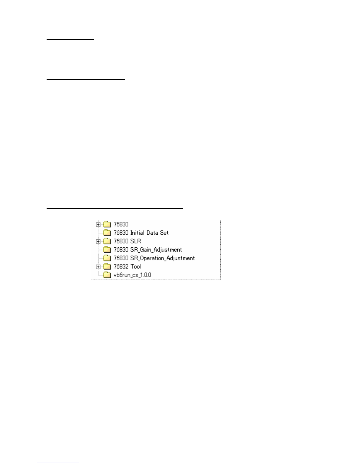
(1) Copy the five holder from the Programmed software contained in the CD-ROM to [C: drive] as shown in
below.
[76830]: For Digital adjustment
[76830 Initial Data Set]: For writhing initial data
[76830 SLR]: For SLR function adjustment
[76830 SR Gain Adjustment]: For SR gain adjustment
[76830 SR Operation Adjustment]: For SR unit adjustment
(2) Copy the file [GM_FW] to the SD card from [76830] holder. (For product FW)
*Use the latest version of firmware. (The file name is “kb421b.bin”.)
(3) Copy the file [DL_FW] to the SD card from [76830] holder. (For updating FW)
*Use the latest version of firmware. (The file name is “fwdc162b.bin”.)
(4) Copy two files in the [Initial Data Set] folder to SD card (For writing initial data)
(5) Complete the setting of [Set up the VB run time] (carry out by K100D or *istDL2)
*Refer to the K100D service manual for details.
(6) Execute [3. Calibration of light source for Digital adjustment]
Page 4

3
3. Calibration of light source for Digital adjustment
Execute Calibration of light source before Digital adjustment.
When replace the light source or master lens for 76180 (D20 or D20-01), this calibration is
necessary.
[Required equipment]
K10D Master body for calibration
(PENTAX Corporation will rend the master body. Please contact with us)
Adjusting software for 76830
Computer (Windows 2000 or Xp, support USB)
Light source (Example: LV3300, A light source)
Master lens for 76180 (D20 or D20-01)
*Use the same master lens as the ID number printed on CD- ROM to adjust it accurately.
3-1. Setting for computer
Complete the [2. Setting for computer and prepare the SD card] of [PREPARTAION].
(Use Digital adjustment software)
3-2. Calibration of light source
(1) Before calibration, turn ON the light source and leave 30 minutes for stabilizing light source.
(2) Calibrate Color temperature and Brightness by using color meter and LV checker as shown below table.
Light
source
Brightness
Color
temperature
LV12 LV12.00Ev ±0.50 2,856K ±30
LV11 LV11.00Ev ±0.01 -
*Calibrate with using the master body according to the following procedure.
3-3. Setting for Master body and Master lens
(1) Set the mode dial to [M].
(2) Set the focus mode lever to [MF].
(3) Set the SR lever to [OFF]
(4) Attach the master lens and F8 set ring to the body.
(5) Set the aperture to [F8 position].
3-4. Procedure for calibration
(1) Connect the AC adaptor to the master body.
(2) Connect to PC with USB cable.
(3) Turn ON the power and confirm that the camera is recognized by PC.
(4) Set the light source to [LV12].
Page 5
4
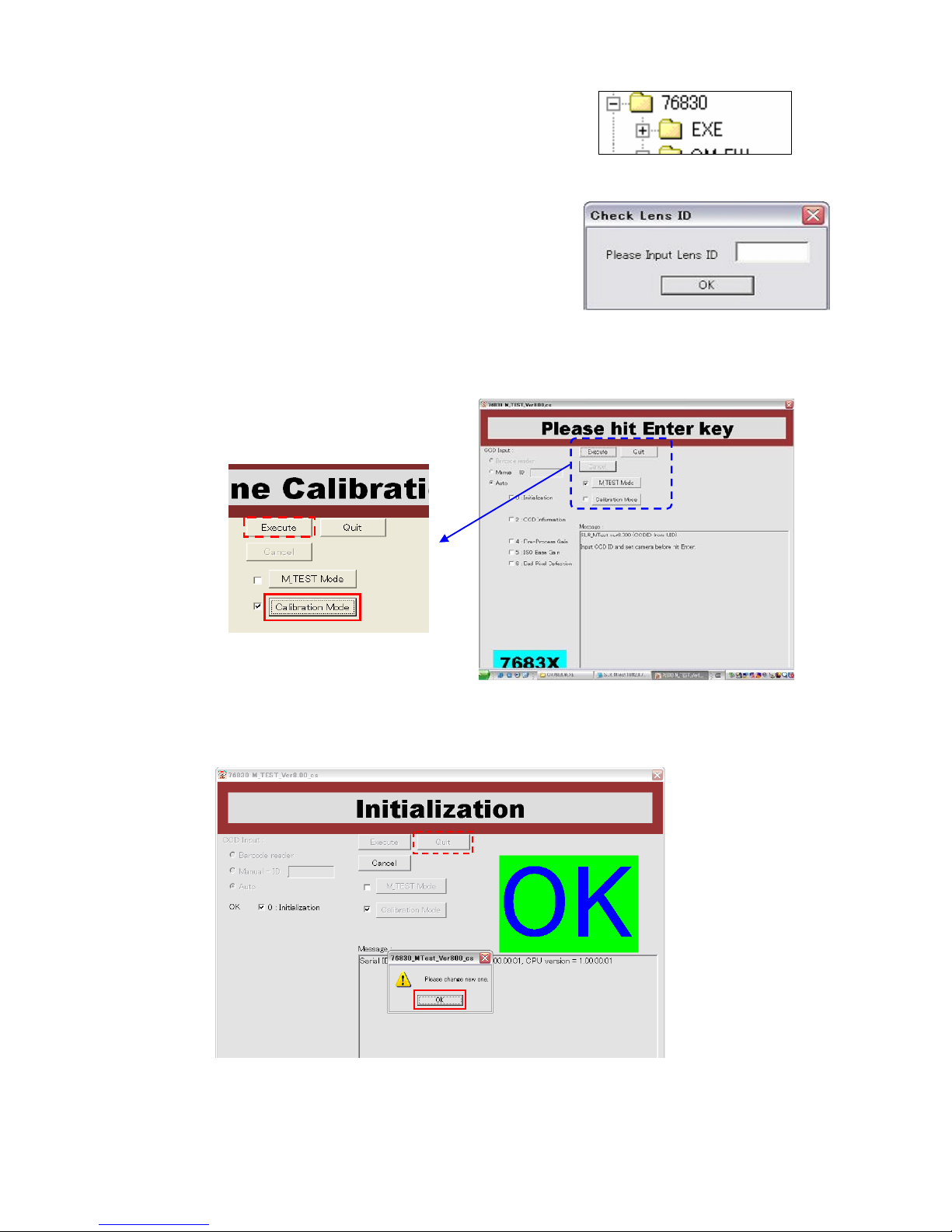
(5) Surely set the camera and lens toward center of light window and
cover the whole camera and light window by using a dark curtain.
(6) Start the adjusting software [76830 MTest.exe] in [EXE] holder.
(7) Input the lens ID number correctly then press [OK] button.
(8) When start the adjusting software, following screen will be displayed.
(9) Click [Calibration Mode].
(10) Press [Execute] button on screen to execute.
(Release 30 times and it takes approx.30 second.)
(11) When calibration is completed, following screen will be displayed.
(12) Press [OK] button and press [Quit] button to finish the adjusting software.
(13) Double click hot plug icon of the taskbar at the lower right of a desktop and then follow
“Safe removal of hardware”. Turn OFF the camera and disconnect the camera.
Page 6
5
Outline of Assembly and Disassembly
1. Caution
(1)Be sure to use the anti-static mat and wrist strap to prevent static failure of circuits.
(2) This product is used lead free solder.
Surface of solder will be white-tinged color. Solder quickly, because melting temperature is
high and so if heat to much, it is possible to damage to PC board.
Soldering iron requirement: The temperature can be adjusted up to 400º and exclusive use
for lead free solder. Also it is desirable to use antistatic soldering iron.
The temperature for tip of soldering iron must set between 340º ~ 360º for lead free solder.
(3) Do not stress to the connector terminals and flexible boards because they are very delicate
parts. Pay careful attention to the connector terminals and flexible boards and, we
recommend marking to the flexible board before disconnecting them. This will be helpful
to reconnect the flexible board to the connector terminal properly.
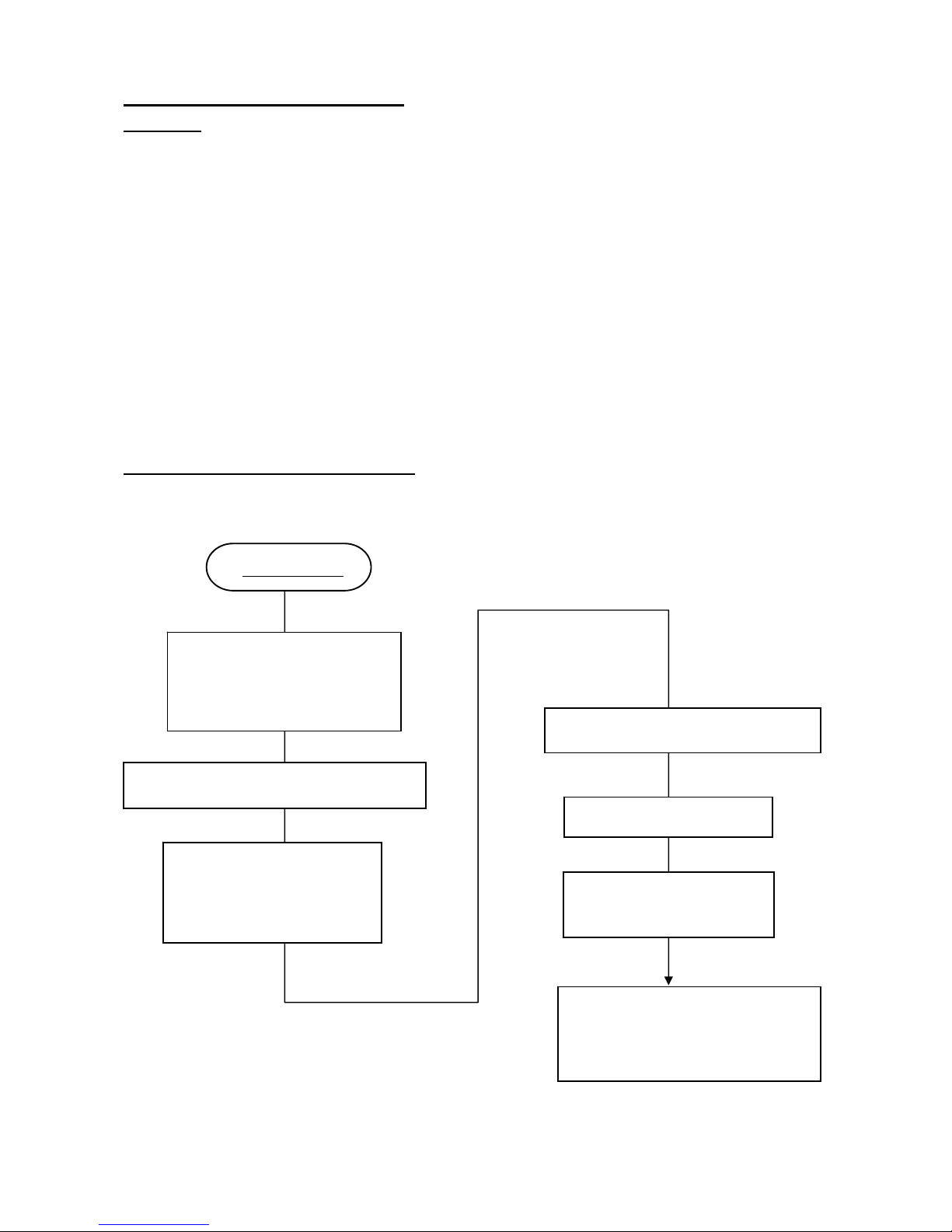
2. Adjustment Flow when replace T100
Following flow chart is method for adjustment when replacing T100.
Replace T100
[Function check]
*SR operation can be skipped
When SR adjustment is completed
[Adjustment]
*Install FW for replacing T100
*Install initial data
SR adjustment I (SR unit adjustment)
SLR function adjustment
(Program software)
Can not be initialized data
SR adjustment II (SR gain adjustment)
Digital Adjustment
Shutter speed adjustment
(Histogram)
Page 7

6
3. Flowchart for Assemble, Adjustment and Confirmation
page
2. ASSEMBLY AND DISASSEMBLY PROCEDURE OF FRONT HOUSING................................
18
(1) FRONT HOUSING BLOCK........................................................................................................... 18
(2) M1................................................................................................................................................... 18
(3) 0-G100............................................................................................................................................ 19
(4) [CONFIRM] CHECKING THE MIRROR FUNCTION..........................................................
21
(5) 0-S300............................................................................................................................................. 21
(6) A104 ……………………………………………………………………………………………… 22
(7) [ADJUST] POSITIONING 1ST AND 2ND MIRROR ………………………………………..
23
(8) [ADJUST] AF JOINT STROKE ……………………………………………………………….
24
(9) L2. 0-L3… ……………………………………………………………………………………….. 24
(10) M301 ……………………………………………………………………………………………. 24
(11) [ADJUST] VIEWFINDER FOCUS AND PARALLAX...........................................................
25
(12) S1 BLOCK ……………………………………………………………………………………... 25
(13) [ADJUST] POSITIONING SI-LED...........................................................................................
26
(14) 0-O100........................................................................................................................................... 26
(15) [ADJUST] POSITIONING 0-O100 (VIEWFINDER INDICATIONS)..................................
27
(16) 0-M100.......................................................................................................................................... 27
(17) 0-J100............................................................................................................................................ 28
(18) 0-T940........................................................................................................................................... 28
3. ASSEMBLY PROCEDURE OF MAIN BODY................................................................................
29
(1) 0-E000 (SHUTTER BLOCK)......................................................................................................... 29
(2) BATTERY CHAMBER AND RELATED PARTS.......................................................................... 29
(3) FRONT HOUSING BLOCK........................................................................................................... 30
(4) A6 (LEFT SHOULDER PLATE) AND RELATED PARTS........................................................... 30
(5) 0-Q200 (FLASH PC BOARD)........................................................................................................ 31
(6) A5 (RIGHT SHOULDER PLATE) AND RELATED PARTS…………………………………… 31
(7) T901 (LOWER FLEX BOARD)..................................................................................................... 31
(8) 0-A3 (BOTTOM PLATE ASSY)..................................................................................................... 31
(9) 0-T750 (TOP LEFT FLEX BOARD)…………………………………………………………….. 32
(10) 0-T700 (TOP RIGHT FLEX BOARD)…………………………………………………………. 33
(11) A350 (MAIN SWITHCH BASE PLATE)……………………………………………………… 34
(12) 0-201 (LCD BLOCK)…………………………………………………………………………… 34
(13) [CONFIRM] CCD BASE PLATE SUPPORT PILLAR..........................................................
35
(14) 0-C000 (SR/CCD BLOCK). ......................................................................................................... 35
(15) [ADJUSTMENT] HEIGHT OF 0-C000………………………………………………………... 36
(16) 0-T970 (SD CIRCUITS BLOCK)……………………………………………………………… 37
Page 8

7
(17) 0-T100 (MAIN PC BOARD)........................................................................................................ 37
(18) 0-T770 (PZ CIRCUITS BLOCK)………………………………………………………………. 37
(19) SOLDERING T100 LEADWIRES……………………………………………………………... 38
(20) 0-A51 (TRIPOD PLATE)……………………………………………………………………….. 39
(21) [ADJUSTMENT] INITIALIZATION WHEN REPLACEING T100………………………
39
21-1 PREPARATION………………………………………………………………………………… 39
21-2 POWER CHECK……………………………………………………………………………….. 39
21-3 INSTALLING FIRMWARE…………………………………………………………………… 39
21-4 WRITHING INITIAL DATA…………………………………………………………………… 40
(22) [ADJUSTMENT] SR ADJUSTMENT (UNIT ADJUSTMENT)…………………………….
40
(23) [ADJUSTMENT] 0-J100 POSITION ADJUSTMENT………………………………………
42
(24 )[CONFIRMATION] CONFIRM SEALING FOR OUTSIDE………………………………
43
(25) A150/A201 (FRONT COVER/BACK COVER)……………………………………………....... 46
(26) A301 (TOP COVER)……………………………………………………………………………. 47
(27) [CONFIRMATION] FUNCTION CHECK 1...........................................................................
48
(BATTERY CONSUMPTION, AF, FI, EXPOSURE MODE, RELEASE, FLASH …ETC)
27-7 [ADJUSTMENT] FLASH STORE POSITION……………………………………………...
49
(28) [ADJUSTMENT] SLR OPERATION ADJUSTMENT……………………………………...
50
28-4 AF SHIFT ADJUSTMENT (OPTIONAL)……………………………………………………. 54
(29) [ADJUSTMENT] SR ADJUSTMENT (GAIN ADJUSTMENT)……………………………
56
(30) [ADJUSTMENT] DIGITAL ADJUSTMENT………………………………………………
57
30-4 WDC ADJUSTMENT (OPTIONAL)………………………………………………………..
58
(31) [ADJUSTMENT] SHUTTER SPEED ADJUSTMENT BY HISTOGRAM………………..
58
(32) A401 (BUTTOM COVER)……………………………………………………………………… 58
(33) [CONFIRMATION] FUNCTION CHECK 2 (FINAL CHECK)………………………………. 58
33-1 CONFIRMATION FOR SR FUNCTION…………………………………………………….. 59
33-2 INITIALIZATION (OPTIONAL) ……………………………………………………………. 59
33-3 FW VERSION UP ……………………………………………………………………………. 59
Page 9
8
DISASSEMBLY AND ASSEMBLY PROCEDURES
1. Disassembly procedure of main body
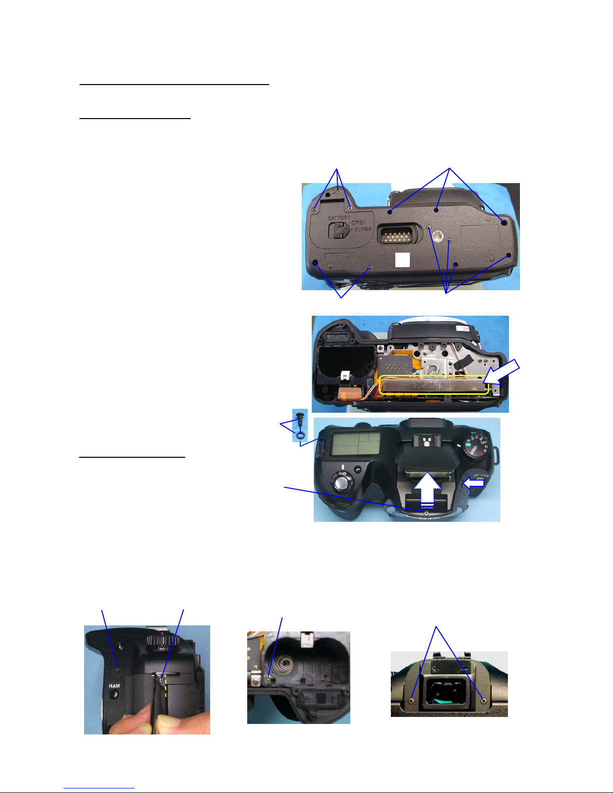
[Preparation] Remove the Hot shoe cover, Eye cap and Battery from the main body.
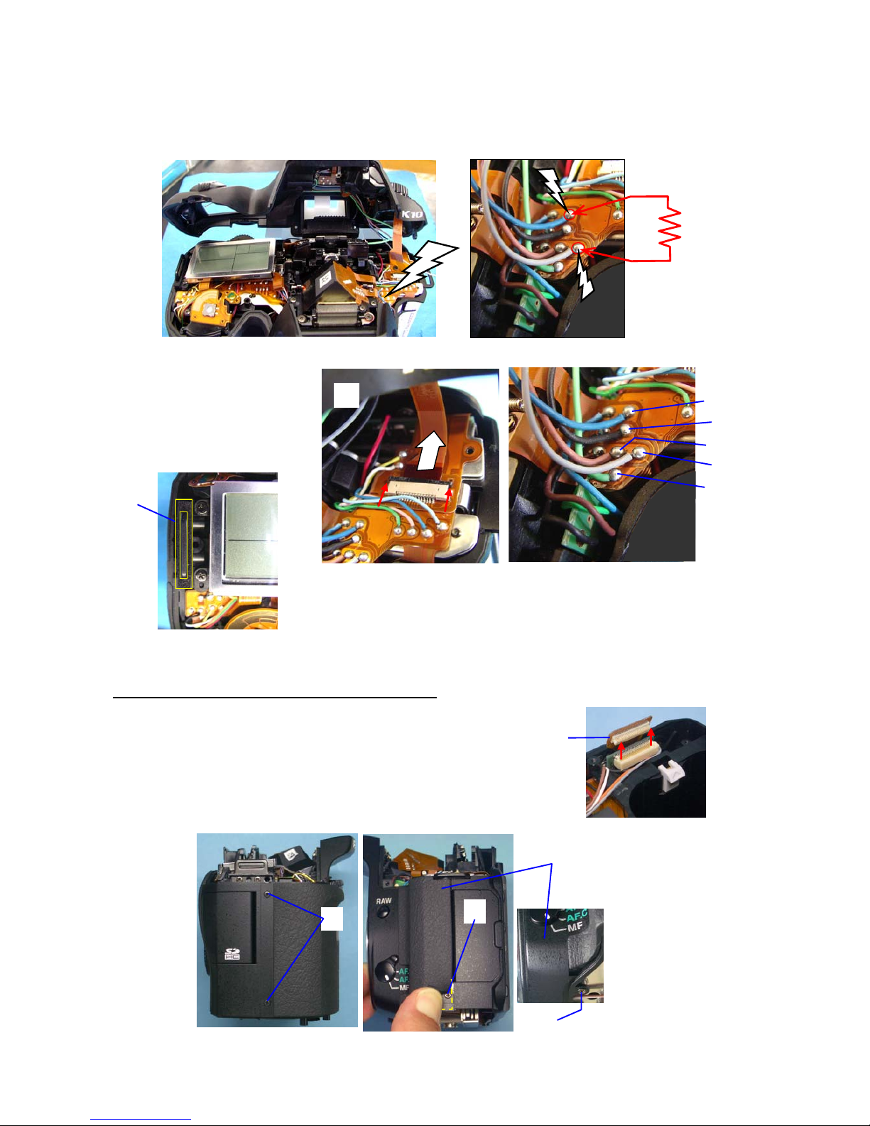
1. A401 (Bottom cover)
[Caution]
There is strong magnet in the CCD/SR blocks therefore please do not place a screw or magnetic card near the
camera after the outside cover is removed.
① Screw (x5)
② Screw (x7)
③ Remove A401, battery cover.
[Caution]
There is SR/CCD block at bottom
side of the camera as shown with arrow, therefore
please pay attention the handling of the camera.
2. A301(Top cover)
① Screw, O ring
② Screw … Pop-up the flash
③ Screw
④ Screw… Peel off the grip rubber
⑤ Screw…(Inside of battery chamber)
⑥ Screw (x2)
[Caution] Be careful the electric shock where flash circuit
board is inside the cover.
①
②
③
①
②
①
②
④
③
⑤
⑥
Page 10
9
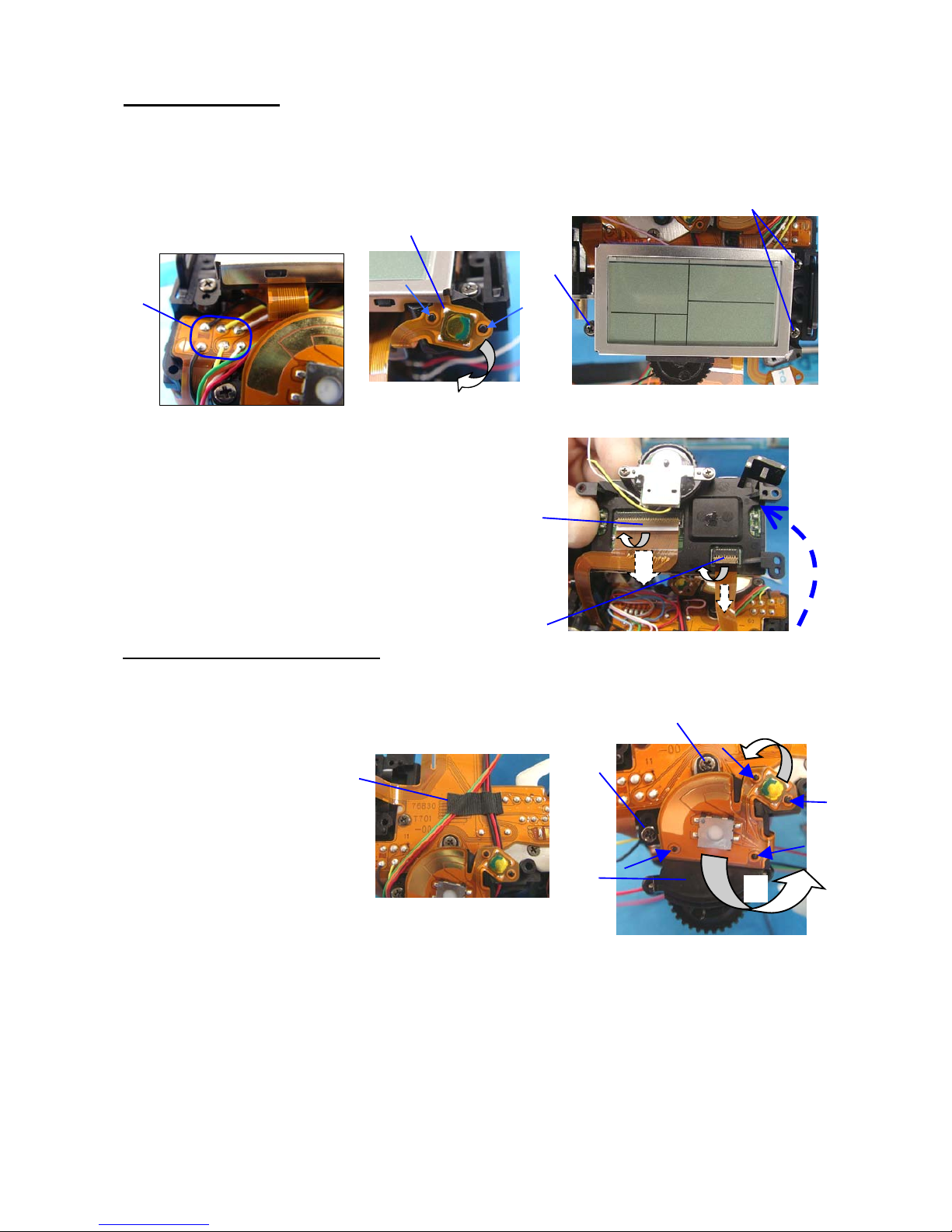
⑦ Discharge the main capacitor
Lift up the A301 then discharge the main capacitor by using 100Ω-1kΩ resistor.
(Discharge between Blue and Brown (gray) soldering land on T750.)
⑧ Disconnect T51 flex board from connector. (Slide lock)
⑨ Unsolder lead 5 wires.
⑩ A301
⑪ A27 (Water proof sheet)
3. A150 and A201(Front cover・Back cover)
① Disconnect T920 flex board from connector. (Plug-in connector)
② Screw (x2)
③ Screw … Peel off the grip rubber.
④ Screw
⑤ A150
100~1kΩ
⑦
⑧
⑨
Blue
Black
Brown
Gray
Green
⑪
①
②
④
⑤
③
Page 11
10
⑥ Put mount cover on the body to protect SI-LED and TV dial part.
⑦ Start from terminal side and then lift up the bottom side
⑧ Loosen the screw then remove a rug plate.
⑨ Screw (x2)
⑩ M311
4. 0-A51(Tripod plate)
① Screw (x4)
② 0-A51
⑥
⑦
⑦-2
Lug plate (27355-I17)
Black (40mm)
⑧
⑨
⑩
①
②
Page 12
11
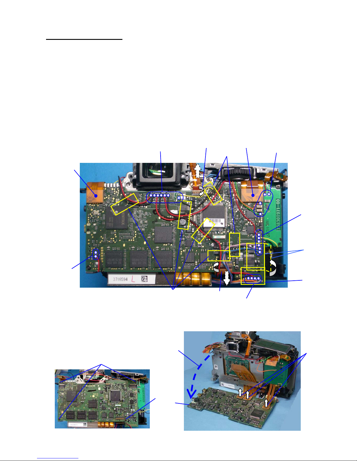
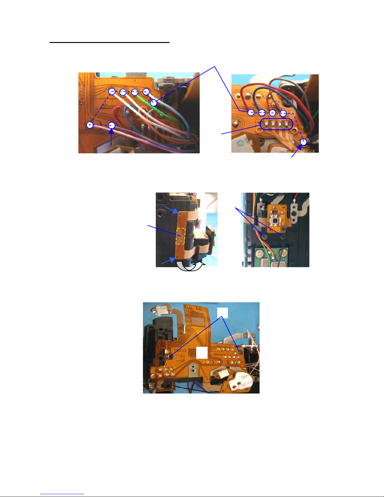
5. 0-T100 (Main PC board)
① Peel off the BT (5x15)… (x6)
② Peel off T90
③ Peel off U5 (76030- A35)
④ Unsolder 7 lead wires
⑤ Unsolder 2 lead wires
⑥ Unsolder 4 lead wires
⑦ Unsolder 6 lead wires
⑧ Unsolder 4 lead wires
⑨ Disconnect flex from connector (2 points Plug-in connector)
⑩ Disconnect flex from connector (2 points Flip lock connector)
…Peel off the J100
⑪ Screw (x3)
⑫Screw (TY-screw)
⑬ Put 0-T100 down as shown in figure bellow.
[Caution]The flex from SR/CCD should be take care carefully, otherwise it will effect the performance of
SR function.
⑭Disconnect flex from connector
(3 points Plug-in connector)
⑮T100
⑬
⑭
⑮
⑪
⑫
④
⑥
⑤
⑦
⑧
⑨
①
①
⑨
⑩
②
③
⑩
Page 13
12
6. 0-T970(SD circuit block)
① Screw (x3)
② 0-T970
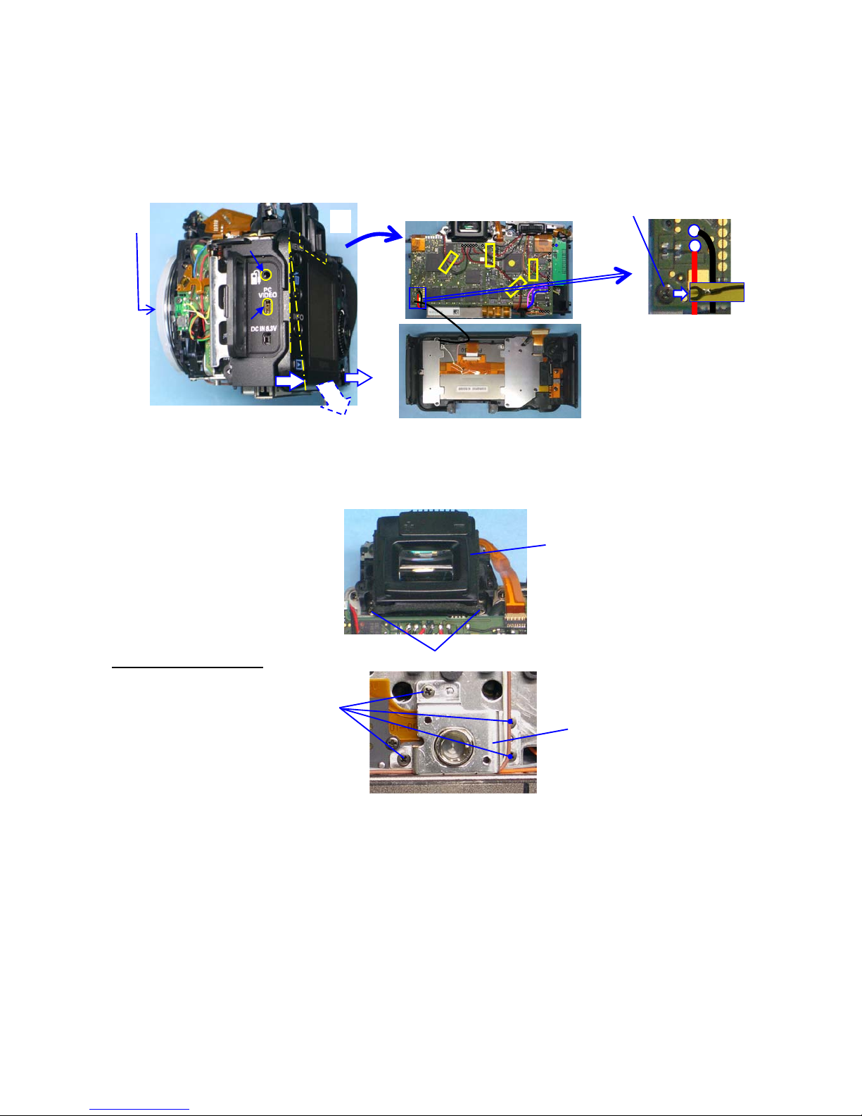
7. 0-T770 (PZ Circuit block)
① Unsolder lead wire x2 (Brown and White)
② Remove shoulder screw
③ 0-T770
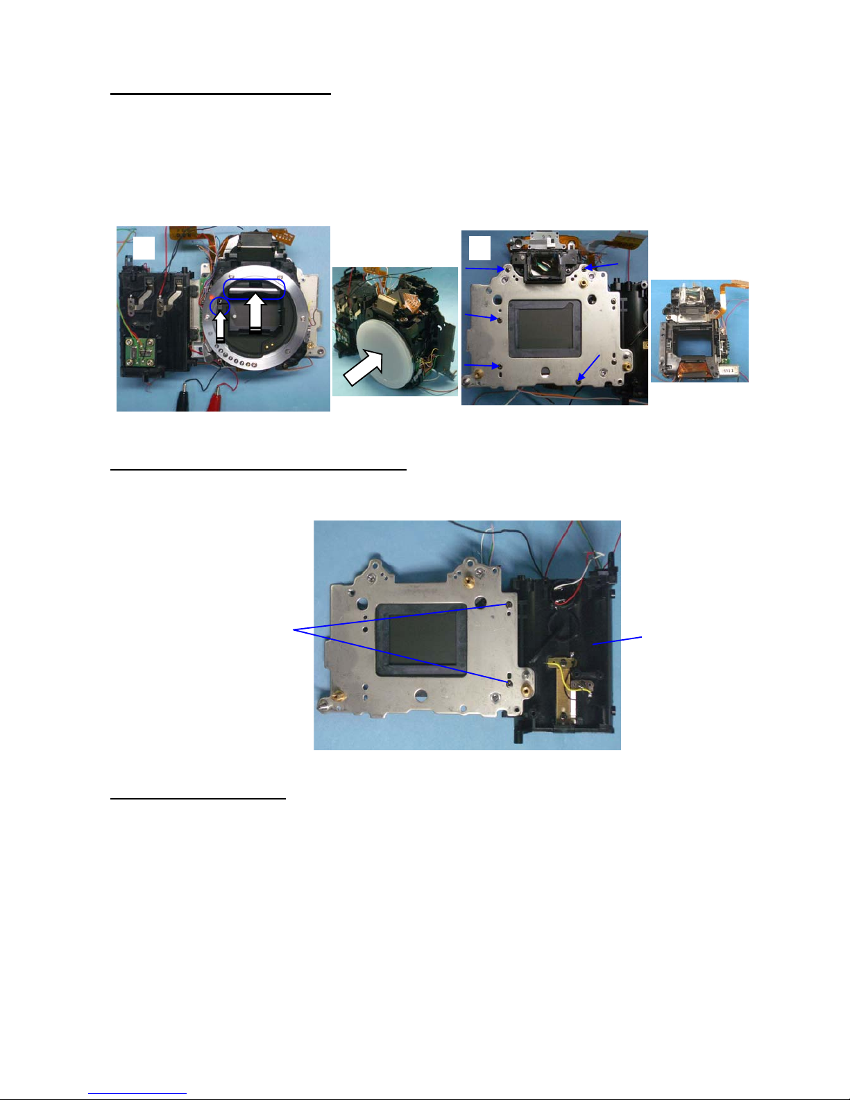
8. 0-C000(SR/CCD block)
[Caution 1] Pay attention, there is powerful magnet is carried in the inside of a CCD/SR block.
[Caution 2] Since a performance is spoiled, a CCD/SR block cannot be disassembled and also don't apply
the external pressure to a movable part
[Caution 3] The flex from SR/CCD should be take care carefully, otherwise it will effect the performance of
SR function.
① Remove the glue with using tools. (3 position)
② A31 Adjusting screws x3
③ 0-C000 --- Do not scratch on surface of CCD.
④ A32 Coil spring x3
①
②
②
③
①
①
②
③
④
Page 14
13
9. O201 (LCD block)
① Unsolder 6 lead wires.
② Peel off [AE-L] SW from double stick tape.
③ Screw
④ TY screw (x2)
⑤ Lift up LCD block as shown figure below.
⑥ Disconnect O100 flex from connector. (Flip lock type)
⑦ Disconnect T700 flex from connector. (Flip lock type)
10. A350 (Main SW retainer plate)
① Peel off BT(6x15)
② Peel off the flex on release SW and Green button SW
③ Screw
④ TY screw
⑤ A350
⑥
⑦
⑤
③
④
①
②
②
③
④
⑤
②
①
Page 15
14
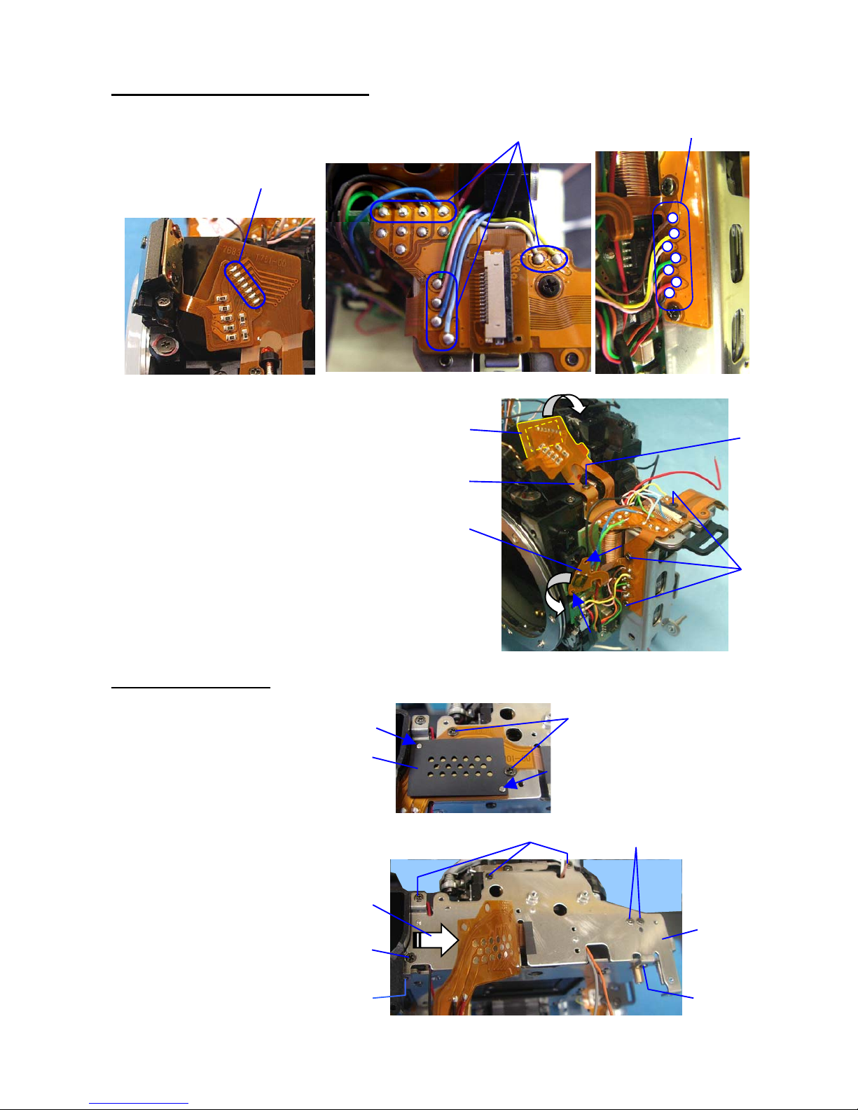
11. 0-T700 (Upper right side flex board)
① Unsolder 12 lead wires.
② Unsolder 4 lands. (T71 flex board)
③ Peel off flex board
④ TY screw (x2)
⑤ Screw (x2)
⑥ T700
③
④
①
②
⑤
⑥
Page 16
15
12. 0-T750 (Upper left side flex board)
① Unsolder 7 lands. (O170 flex)
② Unsolder 10 lead wires.
③ Unsolder 7 lead wires.
④ Screw (x3)
⑤ TY screw
⑥ Peel off the flex of RAW SW
⑦ Peel off the flex of Pentaprism
⑧ T750
13. 0-A3 (Bottom Plate)
① Screw x2
② A423 (Mask)
③ T901 --- lift up flex.
④ TY-CNL-D1.7x2.5 (x2)
TY-CNL-E1.7x2.2 Ni(x2)
⑤ TY-CSM
⑥ TY-CNL-D1.7x4.0 (x3)
⑦ A3
①
②
③
④
⑤
⑥
⑦
⑧
①
②
③
④
⑤
⑥
⑦
④
④
Page 17

16
14. T901 (Lowe flex board)
① Unsolder T301/M100 flex land (20 lands)
② Unsolder two read wires / T901
③ Screw
④ A141
15. A5 (Right shoulder plate)
① CSM screw
② TY screw
③ A5 and related parts.
16. 0-Q200 (Flash PC board)
① TY screw
② A117
③ TY screw
④ 0-Q200
17. A6 (Left shoulder plate)
① CNL-D
② TY-CNL-D
③ TY-CSM x4
④ A6
①
②
③
④
② ③
④
①
①
②
③
①
②
③
④
Page 18
17
18. 0-A101 (Front housing block)
① Supply DC2V to 0-S250 (Mirror motor).
(Positive (+) on Red wire) Set the front housing block to mirror up position.
② Put mount cover on the body to protect SI-LED part.
③ Screws x5
④ 0-A101
19. A13 (Battery chamber) and related parts
① Screw x2
② A13 and related parts.
20. 0-E000 (Shutter block)
① A70 shoulder screw x3
② 0-E000
③ Main plate
④
①
②
③
①
②
Page 19
18
2. Assembly and Disassembly procedure of front housing block
*Disassemble the front housing block in reverse order of assembly procedures.
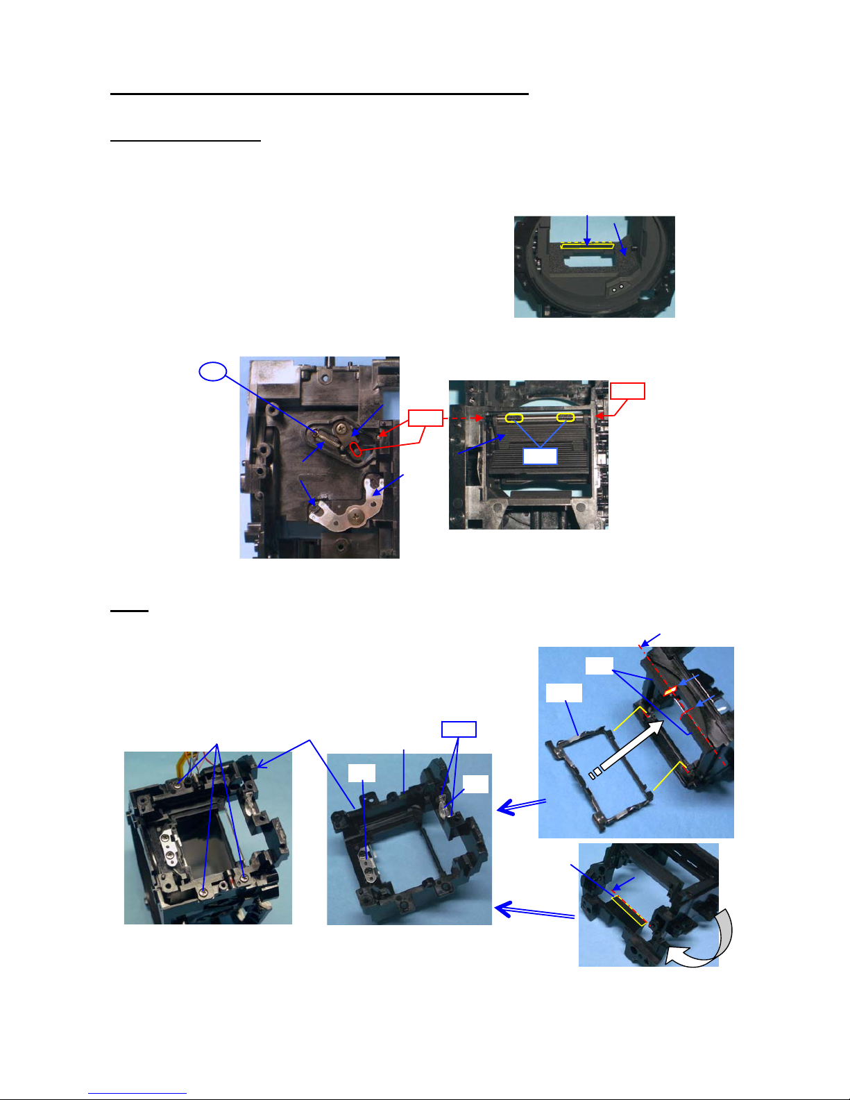
1. Front housing block
B41, M120, (DT(4x15)),
B58 x2, B59, TY-CNL-G 1.7x2.0,
0-B52 (mirror sheet),
B66 (shaft) ----A screw lock (SL) and L115 are applied.
B63, B57
B62 (spring) ---- Apply screw lock.
2. M1
*B65, 0-M4, M6, M7 and M18 are installed on M1.
① M1
② TY-CNLD1.7x4.0 x3
Bond
L115
SL
L115
B65
0-M4
M18
Bond
M1
M7
M6
①
②
Page 20
19
3. 0-G100
① Apply G126 at 13 positions and apply L115 at 2 positions.
② Install B20 to B11.
③ B11 ----Hook the spring to shaft of mirror sheet.
[Caution] Caution for come off spring.
④ B19
⑤ B10
⑥ B21
⑦ Install B17 to B9.
⑧ Install B18 to B9.
⑨ 0-B8
----Apply G126 to surface of cam.
⑩ B7
----Apply G126 to surface of cam on both side.
⑪ Align the both hole of 0-B8 and B7.
⑫ B3
⑬ B4
⑭ B5
⑮ B6
⑯ Turn B7 clockwise until the arrow indicated in figure right.
①
G126
L115
②
③
④
⑤
⑥
⑦
⑧
⑪
⑫
⑬
⑭
⑮
⑨
⑩
⑯
Page 21
20
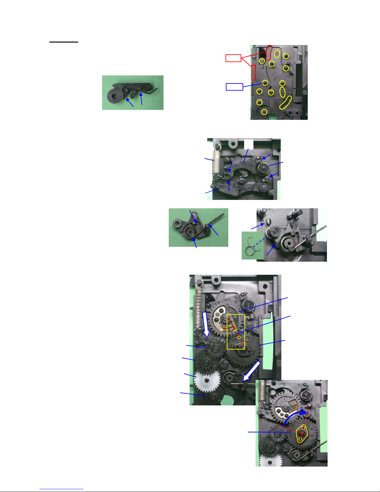
⑰ Clean code plate by solvent and apply G151.
⑱ Latch the lever of G100 while pushing
down the sliding plate.
⑲ 0-G100
----Surely install G100 without any gap between plate.
⑳ TY-CNL-D1.7x3.0 (x4)
[Arrangement when replace G100]
1. Arrange the lead wires with DT (5x15) as shown in figure.
2. Solder 4 lead wires.(Pink, Purple, Red, Black)
3. Affix A364 on the mirror motor by DT (3x6).
⑰
⑱
⑲
⑳
DT(5x15)
Pink (60mm)
Purple (60)
Red (95mm)
Black (95)
S364
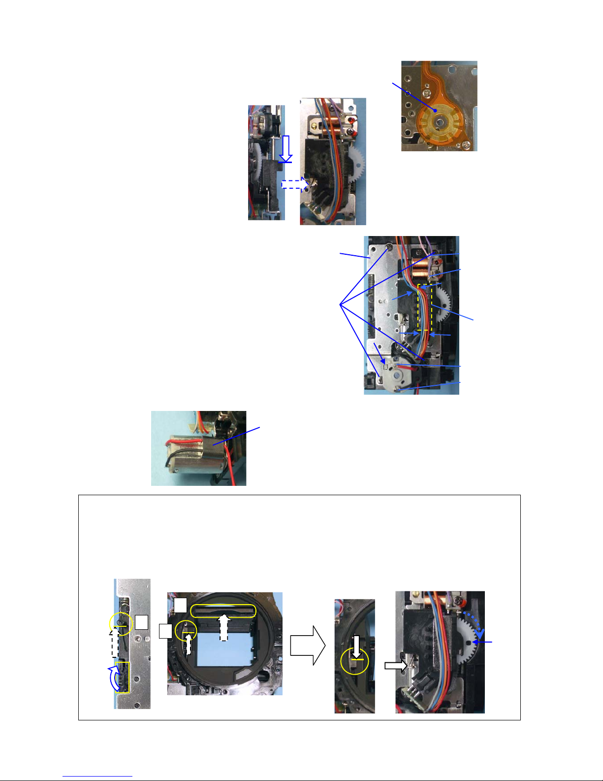
[Notice for Disassembly] Set the mirror seat at top position before removing 0-G100.
1.As shown in a figure, a gear is turned, and it sets to a mirror up position.
Mirror up: (Shutter charge lever(1) and mirror seat(2) and sliding plate(3) must be top end
position. )
2. Latch the lever of G100 while pushing down the sliding plate.
②
③
①
Page 22

21
4. [CONFIRMATION] Checking the mirror function
[Required equipment] Power supply
① Confirm the following points while applying DC2V to the mirror motor. (Red wire: Positive)
-1) The mirror seat must be moved smoothly without noise.
-2) The shutter charge lever(b) and sliding plate(a) must be moved smoothly and surely go up and down.
②Set the mirror seat to the down position while applying DC1.5V.
(Fine adjustment is possible when turn white gear at behind of G100)
Mirror down: mirror, sliding lever, shutter charge lever at down position.
White gear must be positioned as shown in figure.----(※)
③ Both mirror seats 1st and 2nd must be returned smoothly to the original
position when both mirror seats are passed inward about 3mm by finger
pressure.
④ Set the mirror seat to the down position.
5. 0-S300
①Arrange the lead wires from motor and S364 as shown in
figure and then attach 0-S300.
② TY-CNL-D1.7x3.5
③ TY-CNL-D1.7x5.5
④ Apply screw lock.
⑤ Install S364 as shown in figure.
⑥ 0-A115
⑦ TY-CNL-G1.7x2.5
a
※
b
S364
0-S300
①
SL
②
③
④
⑥
⑦
⑤
Page 23

22
6. A104
① 0-A121
② A133
③ TY-CNL-F1.4x4.0
④ 0-A126 and related parts.
Apply G134 as shown in figure.
⑤ TY-CNL-D1.7x3.0
⑥ A105 -- Apply G134 as shown in figure.
⑦ A110
⑧ 0-A108 -- Apply G134 to two shaft part.
⑨ A104
⑩ TY-CNS 2.0x4.5 (Ni-screw x5)
*Tighten screw diagonally as shown in figure.
①
②
③
G134
G134
④
⑤
⑥
⑦
⑧
G134
G134
⑨
⑩
③
④
⑤
①
②
Page 24

23
7. [ADJUST] POSITIONING 1ST AND 2ND MIRROR
[Required equipment] 1
st
mirror angle (45°) adjusting jig, Mirror angle adjusting jig for 27830
(need modify),Mirror positioning scope.
*Adjustment is performed by turning B58 (2 pcs). The Y-axis (the vertical direction) is adjusted
to a 0 target.
*Front housing must set mirror down position.
① Positioning 1 st mirror : Put the 1
st
mirror angle (45°) adjusting jig on the camera,
and then adjust the mirror seat so that the adjusting jig touches the mirror without gap.
Tolerance ---- X-axis : ±15’
Y-axis : ±10’
② Positioning 2
nd
mirror : Attach the mirror positioning scope and the
2nd mirror angle adjusting jig to the camera, and then adjust the
mirror angle while looking through the eyepiece lens.
Tolerance ---- X-axis : ±0.3mm
Y-axis : ±0.1mm
(Refer to below tolerance for positioning scope)
③ After adjustment is done, apply the supper-glue to both B58.
■ Tolerance for 2
nd
mirror position
(Using with the mirror positioning scope)
1st mirror
B58
2nd mirror
1mm hole
OK OK NG NG
Scale
Center of Standard
12
-
2- 1
2
1
- 1
- 2
12
-
2- 1
2
1
-1
-2
NG: 0.8(X) or over
NG: 0.6(Y) or over
:Tolerance of 1 mm hole
(X-axis=±0.
8
、Y-axis=±0.
6
)
Page 25

24
8. [ADJ] AF Joint stroke
[Required equipment] Vernier calipers
① Set the AF lever (0-A115) to the AF.C position.
② AF coupler(0-S300) must be projected from
the mount surface by 1.2mm or more.
③ When the mount lock pin comes to the mount surface
with depressing the mount lock lever, the AF coupler
must not be projected out of the mount surface.
④ Adjust 0-A121 by turning an eccentric screw,
and apply the screw lock.
9. L2 and 0-L3
[Caution] Confirm there is neither dust nor scratch on L2 and 0-L3.
① M3
② 0-L3
③ Tighten M16 (Adjustment screw) temporary
while pushing 0-L3 front side.
④ Down the focusing screen frame (0-M4) by releasing the hook portion.
⑤ Push the arrow part in figure and install M22.
In the case of temporary adjustment, Using with the M22-00E(0.35).
⑥Put the focusing screen (L2) on the frame and then push it back until it locks in place.
10. M301
① Eyepiece (M301,L7 and other)
② TY-CNL-D1.7x4.0(x2)
④
⑤
⑥
①
②
SL
①
②
③
④
①
②
③
Page 26

25
11. [ADJUST] VIEWFINDER FOCUS AND PARALLAX
[Required equipment] 50mm lens, Collimator, Focus master lens
[Preparation]
1. Adjust the diopter by the diopter adjustment lever.
2. Set the AF mode switch to to MF position. (Upper position)
11-1. Parallax
[Caution] Confirm that the Pentaprism must be installed securely.
①[Confirmation]Confirm there is neither gap nor an inclination at an upper and lower, Right and left
position.
② [Adjustment] Adjust right and left position by turning M16 x2.
③ Apply screw lock to M16. (4 position)
11-2. Viewfinder focus
①[Confirmation] Confirm a viewfinder focus.
*One scale for focus master lens is 0.03mm.
Standard: 0±0.06 mm
② [Adjustment] Exchanges for M22 of other thickness.
The tolerance level at the time of adjustment is 0±0.04 mm.
M22-00A -00B -00C -00D -00E -00F -00G -00H -00I -00J
t=0.15 0.20 0.25 0.30 0.35 0.40 0.45 0.50 0.55 0.60
12. SI block
① Confirm that there is neither dust nor scratch on inside prism and mirror.
② SI block(0-M51, 0-M52, M53, L11, L12, 0-O170 and other)
③ Attach M55 (SI spring) as shown figure
④
TY-CNL-F1.7x4.5(x2)--- Install SI block and M55(spring) to the pentaprism side as shown figure
⑤ Apply screw lock
③
④
①
②
⑤
SL
Standard: Right/Left Less than 1°
Upside down Less than 1°
SL
SL
③
②
②
Page 27

26
13. [ADJUST] POSITIONING SI-LED
[Required equipment]Power supply, lead wires
① Solder and arrange the lead wires on 0-O170 as shown in the figure below.
[Caution]Do not stress to the lands of 0-O170.
② Apply DC3.2V to 0-O170, and confirm the positioning
And lighting of SI-LED 11points.
③ [ADJ-1]Loosen 2 screws, and then adjust the position of 0-O170.
④ Tighten 2 screws, and then confirm the position again.
⑤ [ADJ-2]Turn adjusting screw to adjust fine adjustment for up
and down position then confirm the position again.
⑥ After adjustment is done, apply the screw-lock to 5 points
and remove the lead wires from 0-O170.
⑦ A mount cover is attached in order to protect a SI-LED part hitting during work.
14. 0-O100
① Apply small amount of dia bond (Black) as shown in figure.
② M9
③ M2 prism -- Make sure that there is no dust on M2.
④ 0-O100
⑤ TY-CNL-F1.7x3.0 x2 -- Temporally tighten screws while
holding 0-O100 plate.
: SI-LED AF frame
(+) DC3.2V
(-)
0-O170
①
②
ADJ
⑤
⑥
SL
ADJ
③
⑥
⑦
①
②
③
④
⑤
[Note of Disassembly]
1. Remove the screw lock which is stick to the screw.
2. Unscrew (x2) while pressing the plate of 0-O100.
3. If M2 does not replace, you do not necessary to disassemble.
Page 28

27
15. [ADJUST] POSITIONING 0-O100 (VIEWFINDER INDICATIONS)
Preparation: O100 cable for 76830, O100 positioning jig for 76700, Power supply (8V, 3A).
15-1 Preparation
① Connect the 0-O100 cable for 76830 to the jig as shown figure.
② Connect the flex board of 0-O100 to the cable.
③ Apply 6.0 V to the jig.
④ Turn the main SW ON.
⑤ Turn the mode SW ON.
*Indication of O100 is display
15-2 Adjustment
① [Confirmation] Check whether the position of the display is straight.
② [Adjustment] Loosen the screw and change the position.
③ After adjustment is done, apply screw lock.
16. 0-M100
Preparation: Hexagonal screwdriver 1.5mm
① 0-M100 (when replacing 0-M100 put M125 at sensor side)
[Caution] There is no dust and stain on the surface of lens.
②TY-CNL-D1.7x4.0 (x3)
[ADJ] Temporary adjustment of AF block --- Screw in 3
adjusting screws until they stops, then screw back two turns.
[NOTE] After CCD position adjustment with programmed
software is done, Apply screw-lock agent to between the
head of adjustment screws and washers.
③
DC6V
①
⑤
④ MAIN
②
①
SL
②
③
②
①
③
M125
Page 29

28
17.0-J100
① M10 -- Set the diopter lever at end of left side and
then install it.
② 0-J100
③ M5-TY-CNL-G1.7x5.0(Temporary)
18. 0-T940
① Set AF mode lever to AF.S (Center position)
② 0-T940
③ TY-CNL-D1.7x3.0
[Caution for disassembly]
When take off 0-T940, the AF lever should be set
At center (AF.S)
①
②
③
①
②
③
[Caution]--- Disassembly
1. Set the Diopter lever to the left side.
2. Unscrew TY-CNL-G1.7x5.0 -M5.
3. Remove the bonds which are around the 0-J100.
* Not to damage 0-J100
4. 0-J100, M10
Page 30

29
3. ASSEMBLY PROCEDURE OF MAIN BODY
1. 0-E000 (Shutter block)
① Main body
② 0-E000
③ A70 x3 (Shoulder screws)
*Tighten A70 in numeric order.
④ Arrange 5 lead wires by DT (5x5) as shown in figure.
*After install, 0-E000 has a little movement.
2. A13 (Battery Chamber) and related parts
① A13 (Battery Chamber) and related parts.
[Confirmation] Each parts are installed properly.
[Caution] *A16: Apply superX (Black) as shown in figure. Do not apply out of red square area.
** Install A75 to 0-T950 properly. Make sure there is no deformation.
There is the gap between side of PC board and A13.
③
②
①
④
③
①
②
TY-CNL-D1.7x3.5
A19
A12
A14
Black, Red
TY-CNL-D
1.7x2.8
A18 (Black, A17)
A23 (Yellow)
A28
DT(2x15)
N300: Super-X x3
White, Red
**A75, W113,
A76(screws) (x4)
**0-T950
Red
Orange
Green
Black
*A16
TY-CNS2.0x4.5
Super-X (Black)
TY-CNL-D1.7x2.8
Page 31

30
② A13
③ Main body
④ TY-CNL-D1.7x4.0 x2
3. 0-A101 (Front housing block)
① Apply DC 2V to the mirror motor, and set mirror up position.
(Red --- +)
② To prevent the damage of SI-LED, attach mount cover. Then put downward.
③ Put main body to the front housing without pinching lead wire or flex.
④ TY-CNS2.0x5.0 x5
⑤ Apply DC2V to the mirror motor, and set mirror down position.
[Caution] Do not make scratch on the eyepiece lens while working.
4. A6 (Left shoulder plate)
① A6 -- Arrange the lead wires and flex as shown in figure.
② TY-CSM1.7x4.0 x4
③ TY-CNL1.7x4.0
④ CNL-D1.7x2.5
④
②
③
①
②
④
⑤
①
④
③
②
Page 32

31
5. 0-Q200 (Flash PC board)
① 0-Q200 --- Arrange the lead wires as shown figure.
② TY-CNL-D1.7x3.5(bottom side)
③ A117
④ TY-CNL-D1.7x3.5
6. A5 (Right shoulder plate) and related parts
① A5 and related parts
--
Arrange the lead wires as shown figure.
② TY-CNL-D1.7x4.0
③ CSM1.7x2.5
7. T901 (Lower flex board)
① A141
② TY-CNL-D1.7x3.5
③ T901 (Red and Black lead wire)
④ T301 and M100 flex land 20 position.
8. A3 (Bottom plate)
① Make sure there is two tape on 0-A3
④
③
②
①
③
②
①
②
①
③
Black Red
④
Page 33

32
②
Arrange the lead wires and flex as shown figure then install 0-A3.
③ TY-CNL-D1.7x4.0 x3
④ CNL-D1.7x2.5 x2
⑤ TY-CSM1.7x4.0
⑥ TY-CNL-E1.7x2.2 Ni x2
⑦ Arrange T901 flex and 0-A3
as shown in figure.
⑧ A423 (Mask)
⑨ CNL-D1.7x1.6 x2
9. 0-T750 (Upper left side flex board)
① 0-T750 -- Attach to the body
② CNL-D1.7x1.6 x3
③ TY-CNL-B1.4x2.5
④ Fix Pentaprism with DT (10x18)
⑤ Fix RAW button SW with DT (5x5)
⑥ Solder 7 lead wires.
⑦ Solder 10 lead wires.
⑧ Solder 7 lands. (O170 flex)
②
③
⑤
④
①
⑥
Brown
Yellow
Pink
Green
Orange
Red
⑦
White
Yellow
Green Black
Brown Blue
Green
Pink
Blue
Sky-blue
⑧
⑦
⑥
⑤
②
④
④
③
⑨
⑧
Page 34

33
10. 0-T700 (Upper right side flex board)
① 0-T700 --- Attach to the body
② CNL-D1.7x1.6 x2
③ TY-CNL-D1.7x3.5 x2
④ Fix flex with DT (10x4)
⑤ Solder 4 lands. (T71 flex)
⑥ Solder 12 lead wires.
②
①
⑥
⑤
Red Orange
Blue Gra
y
Black (A105)
Pink Sky-blue (E000)
White Green Black
Pink Purple
(G119 / G100)
④
③
Page 35

34
11. A350 (Main SW plate)
① A350
② CNL-D1.7x3.0
③ TY-CNL-D1.7x4.5
④ Fix the flex which around release SW/Green button SW with DT (5x5)
⑤ Arrange the lead wires with BT (6x15).
12. O201 (LCD block)
① Connect T700 flex to connector (flip lock type)
② Connect O100 flex to connector (flip lock type)
③ O201… Attach to the body
④ TY-CNL-D1.7x4.5(x2)
⑤ CNL-D1.7x2.5
⑥ Fix [AE-L] flex part with DT (5x5)
⑦ Solder 6 lead wires.
②
①
③
④
②
③
①
⑤
⑤
④
⑥
⑦
Black, Yellow, White
Black
,
Yellow, White
Page 36

35
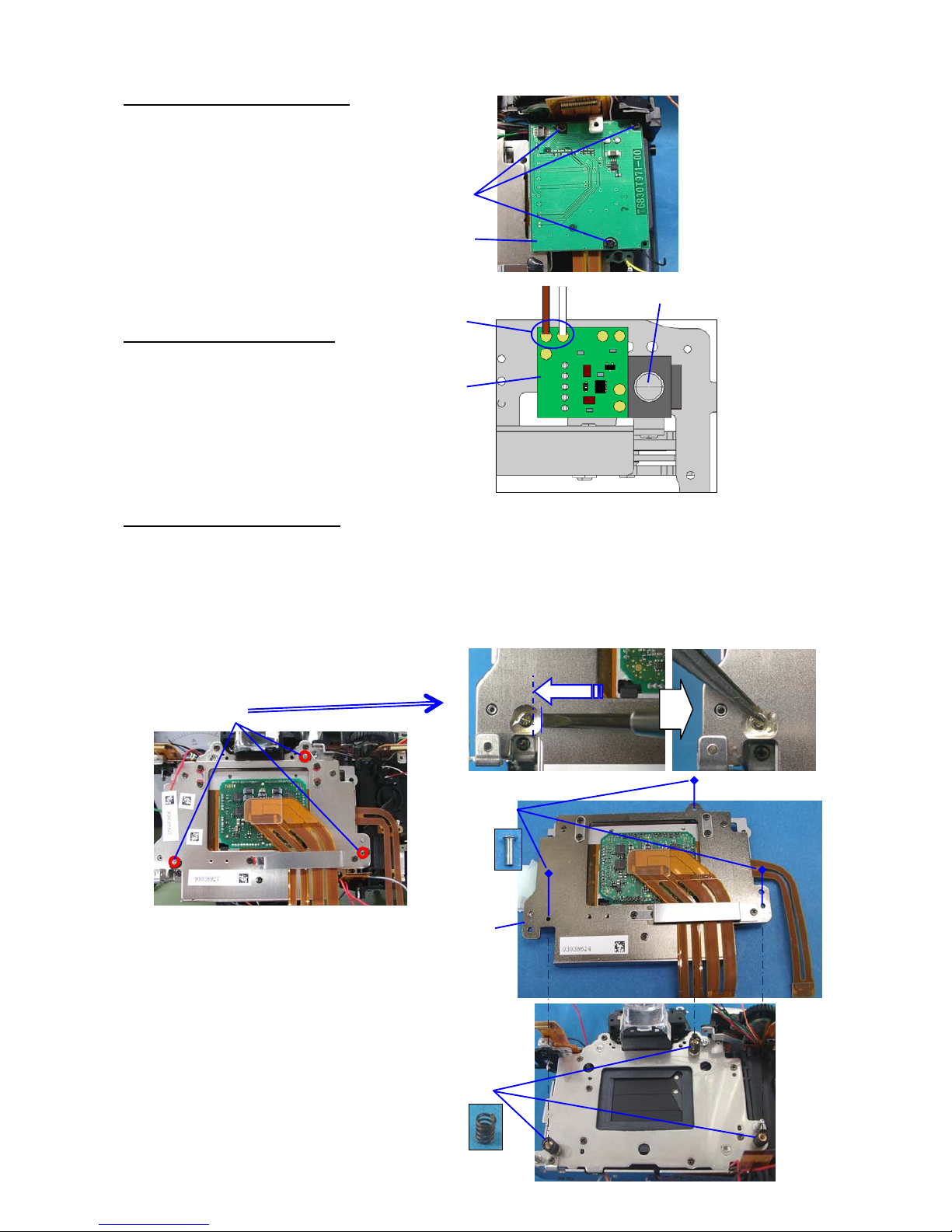
13. [CONFIRM] CCD BASE PLATE SUPPORT PILLAR
[Required equipment] Block gauge for 35mm, Dial gauge comparator, etc. (same as *istD or K100D )
① Measure height of the CCD base support pillar (3 places) from the mount surface as shown in the figure.
Tolerance (For 76830 only): 49.45±0.1 mm
With using Block gauge for 35mm (45.46mm):
+3.89~4.09 mm
14. 0-C000 (SR/CCD block)
[Caution-1] CCD/SR block has strong magnet inside, therefore caution for adsorption of parts.
[Caution-2]Since a performance is spoiled, a CCD/SR block cannot be disassembled and also don't apply
the external pressure to a movable part
[Caution-3] The flex from SR/CCD should be take care carefully, otherwise it will effect the performance of
SR function.
[Caution-4] There is no scratch or dust on the CCD surface.
*To prevent the damage of SI-LED, attach mount cover. Then put downward.
① A32 Coil spring x3 – install to pillar.
② [Confirmation] Center plate must move up and down and right and left by own weight.
③ Arrange lead wire and flex then install CCD/SR block according to the guide pin of the plate.
[Caution] A32 must not come off and adsorption to magnet.
④ A31 adjusting screw x3 – Tighten A31 until stop while pressing to main body.
⑤ [Adjustment] Height of 0-C000, temporally adjustment by A31 x3 - Screw back two turns.
+3.
+0.89~1.09
④
③
①
②
⑤
Page 37

36
15. [ADJUSTMENT] HEIGHT OF 0-C000
[Required equipment] Block gauge for 35mm, Dial gauge comparator, etc. (same as *istD series or K100D)
Specified glue: Cemedine Super-X (Clear) --- Order number 95901 A133
① Measure height of the CCD rear plate (3 places) from the mount surface as shown in the figure.
② [Adjustment] Turn three adjustment screw A31. Target for adjustment is +5.83±0.00 (Maximum
and minimum difference is within 0.01)
You must finish the adjustment with turning A31 tighten direction. (Clockwise direction)
③ After adjustment, clean A31 and around A31 by solvent then apply super-X on the top of screw
as shown in figure.
Confirm for not
disassembled body
When adjusting
Tolerance (For 76830 only): 51.22~51.37 mm 51.29±0.01 mm
With using Block gauge for 35mm
(45.46mm):
+5.76~5.91 mm
+5.83±0.01 mm
(+5.82~5.84 mm)
[Caution] When replacing 0-C000:
1. There is CCD ID No. seal on the plate. *The No. can be readable.
2.Peel off the seal on the plate then replace the seal on the pentaprism.
*
①
+5.
+0.83
②
ADJ
③
Super-X
(Clear)
A31
Exampl
Page 38

37
16. 0-T970 (SD circuit block)
① 0-T970 --Arrange the 4 lead wires as shown figure.
② TY-CNL-D1.7x3.5(x3)
17. 0-T100 (Main circuit block)
① Set up T100 as shown figure.
② Connect 3 flex. (Plug-in type)
③ Attach T100 to the body and connect to the
Connector. (Plug-in type)
④ CNL-D1.7x2.5 x3
⑤ TY-CNL-D1.7x3.5
⑥ DT(4x4)
⑦ DT(4x15)
18. 0-T770 (PZ circuit block)
① 0-T770
② Shoulder screw (27355 –D35)
③ Two lead wire (Brown and White)
②
①
③
②
①
④
⑤
⑦
⑥
④
②
①
③
Page 39

38
19. Soldering lead wires on T100
① Connect flex to connector. (2 point, Flip lock type)
Fix J100 flex with DT
② Connect flex to connector. (2 point, Plug-in type)
③ Solder 4 lead wires.
④ Solder 6 lead wires.
⑤ Solder 4 lead wires.
⑥ Solder 2 lead wires.
⑦ Solder 7 lead wires.
⑧ BT(5x15)…x6
⑨ T90 Hold
⑩ U5 (76030-A35)
⑦
③
(Q200) (T901) (A14)
Black Black Black
Red Red Red Black(T950)
Orange
Gray
(
S300
)
Black Red
(S250)
(N300)
Red White
Orange
Green
(T950)
⑥
④
⑤
②
⑧
⑧
②
①
Black
Red
(T770)
Red (T950)
Yellow
Black (A18)
Pink (T770)
Purple
⑨
⑩
①
Page 40

39
20. 0-A51(Tripod plate)
① 0-A51
② CNL-D1.7x2.5 x4
③ Arrange lead wires as shown figure.
(S300 and T770)
21. [Adjustment] Initialization when replacing T100
[Caution] When replacing T100, you must execute this initialization. Do not execute with other reason.
[Required equipment]
SD card SD card 2 pieces (FW for replacing T100, for install initial data), TV monitor, Exclusive
Video cable, Circuit tester, AC adaptor (or DC cord for 76830, Power supply DC8.3V/3A or above)
21-1. Preparation
① Connect the TV monitor by Video cable.
② Solder main switch land on T200.
21-2. Power check
① Connect to the power supply by DC cord and set DC8.3V/3A.
② Connect the DC cord to the camera. Confirm that there is no short circuit or leak.
[Caution] If there is short circuit, disconnect the power immediately.
With this condition battery current is approx.320mA (metering switch off).
③ Disconnect DC cord.
21-3. Installing FW for replacing T100
[Caution] All setting will be cleared
① Connect the Video cable and AC adaptor to the camera.
② Surely install SD card (FW for replacing T100) to the card slot.
③ TV monitor will be displayed as right Fig.
If you cancel installation, disconnect AC adaptor first then remove SD card.
④ When [>>> EJECT SD CARD <<<] is displayed, remove the SD card.
Installation will be started. It takes approx.90sec. (UPDATING…)
[Caution]Do not turn OFF the power.
⑤ When [POWER OFF] is displayed, disconnect AC adaptor.
*leave the video cable.
①
②
DT(4x15)
DT(4x10)
②
DETECTED BOTH F/W FILE
NOW LOADING
DETECTED FIRMWARE FILE
COMPLETE LOADING
------- CPU --------
CURRENT VER.1.00.00.00
UPDATE VER.1.00.00.10
======= DSP ========
CURRENT VER.1.00.00.00
UPDATE VER.1.00.00.10
>>> EJECT SD CARD <<<
SAMSUNG GX10
UPDATING DSP FIRMWARE
SECTOR** >> PROGRAM
_____________
NEVER POWER OFF
SAMSUNG GX10
UPDATING DSP FIRMWARE
**** COMPLETE ****
VERSION 1.00.00.10
POWER OFF
Main SW
Land
Page 41

40
21-4. Data initialization
[Caution] If execute this initialization, all EEPROM data will be initialized (Cleared)
① Install SD card (For data initialization) to the camera.
② Connect the AC adaptor. (Initialization will be started.
It takes approx 20 sec.)
[Caution] Do not turn OFF the power
③ When monitor display is turn off, (“WAIT…” → “COMPLETE…” →)
disconnect the AC adapter.
22. [Adjustment] SR adjustment- 1 (Unit adjustment)
[Caution-1] When replacing T100, T970 or C000, you must execute this adjustment.
[Caution-2] Execute the adjustment on the stable table and do not give vibration to the camera while
adjusting
[Required equipment] Programmed software for 76830 (for SR unit adjustment), SR adjustment stand
Computer (Windows 2000 or Xp, USB port as standard equipment), USB cable, AC adaptor (DC cord for
76830 and power supply DC8.3V)
22-1. Setting for computer
Copy the folder [76830 SR Operation Adjustment] to the PC
22-2. Preparation
SR adjustment stand
①Set the AF mode lever to [MF].
② Attach SR adjustment stand to the camera
③ Put the camera on the stable table with
lens downward.
④ If replace T100, confirm the CCD ID number.
22-3. Procedure for adjustment
① Start up the computer.
② Connect the camera to the computer via USB cable and connect the AC adapter (Power ON).
③ Confirm that the camera is recognized by computer. (Hot plug icon).
④ Click [
K10D SR Operation cs.exe] in the adjustment software folder
⑤ Adjustment screen will be displayed.
⑥ Click [Start] to execute the program
76830 SR Operation Adj ustment
USB cord
DC cord
CCD ID No.
WAIT(1) Install SD
card (For data
initialization
)
to the
COMPLETE…
VERIFY:****
Page 42

41
⑦ CCD number input screen is displayed.
⑧ Select Input or Skip and execute the program.
<Not replace T100 or C000>
Click [Skip]
<Replaced T100 or C000>
Input I-CCD number twice.
Click [IMPUT]
* If cancel the adjustment, click [CANCEL]
⑨ Adjusting screen (It takes about 3.5 minute)
[Caution]
Do not give vibration to the camera while adjusting, also do not even walk around the camera also.
If you give vibration to the camera while adjusting, repeat the adjustment even pass the adjustment.
*If you want to stop the adjustment, click [Stop].
⑩
When the following screen is displayed, adjustment is completed.
⑪ Confirm that “Unconnect” is displayed then click [x] to finish the adjustment.
*If adjustment is NG, green part will be changed to red.
⑫ Unsolder main SW land on T200.
Main SW
Land
Page 43

42
23. [Adjustment] Positioning 0-J100
[Required equipment] Penlight or equivalent
*Adjustment and confirmation are the same as K100D. Refer to the service manual of 76700.
① [Confirm] Tolerance
② Adjust the position.
③ Apply the bond/Screw lock as shown in figure.
AF frame for spot metering (φ2.5)
J100
③ Bond
② ADJ.
③
SL
M15
Photo sensor (0-J100)
Center position of sensor
Tolerance:0.25~0.85mm
Center position of Viewfinder
Page 44

43
24.[Confirmation] Sealing on Body
[Confirmation] The sealing should be installed correctly and without any dirt, dust and sand.
① Front and back side electric dial.
[Confirmation] When rotate the electric dial, it should not touch with a proof sheet.
② M311
A353
A352
A1
A352
A355
A471 x2
A463 x2
Page 45

44
③ A150
④ A201
A
451
A
453
A
453
A474 x2
A
457
A
451
A
456
A
456
A
204
Page 46

45
⑤ A301
⑤ A401
[Caution]
• Pay attention that sealing material should not pulling or twisting
• Install the sealing material carefully, especially when install the part of the curve, especially the
periphery of A301, A401, and M311
• If the sealing material has a crack, crushing, cutting, etc., it should be replaced with new one
• When the disassembly/Assembly repeated, the performance of dust-proof, water-resistant
construction will be falls.
• Deterioration of the sealing will progress according to the use conditions and the storage
conditions. Immediately replace it by a new one if it is damaged, shows cracks, or has lost its
elasticity.
A461
A462
A460
A
472
A54
A455
A454
Page 47

46
25. A150 and A201(Front cover and Back cover)
① M311
② CNL-D1.7x3.0 x2
③ Prevent the damage of SI-LED and Tv dial attach mount cover.
④ A98(O-ring)---There needs to be no adhesion of crushing, a crack, dust, etc in O-ring.
⑤ 27370-A115
⑥ Place camera body and A201 as shown figure
⑦ The lug plate from rear cover fix with screw (See the direction of the lug plate)
⑧ A201 --- Attach rear cover to the eyepiece part first and then terminal side.
⑨ A150・・・Set the AF-SW to MF
⑩ CNL-D1.7x3.0
⑪ CNL-D1.7x3.5…Peel off the grip rubber.
⑫ A172(TY-screw 1.7x4.5, x2)
⑬ Connect T920 flex to connector (Plug-in type)
↓
②
①
⑬
③
④
⑤
⑧
Lug plate (27355-I17)
Black (40mm)
⑥
⑦
⑫
⑨
⑪
⑩
Page 48

47
26. 0-A301(Top cover)
*The brush should be without bend
*Apply G151 to the main SW land.
① A27(Water proof sheet)
② 0-A301
③ Solder 5 lead wires.
④ Connect the T51 flex to the connector(Slide lock)
⑤ A173(TY-screw 1.7x6.0 x2)
⑥ A171(TY-screw 1.7x4.0, A304(O-ring)
⑦ A171 --- pop-up the flash.
⑧ CNL-D1.7x5.5 --- peel off the grip rubber.
⑨ A173
⑩ TY-CNL-D1.7x8.0(In the battery chamber)
⑧
⑨
⑩
⑤
④
①
③
Blue
Black
Brown
Gray
Green
G151
⑥
⑦
Page 49

48
27. [Confirmation] Function check 1
[Required equipment] Battery adaptor for 76830, DC code for 76830, Regulated DC power supply (8V/3A),
SD card, Circuit tester, Lens for checking (FA50mmF1.4), Battery grip D-BG2, Cable switch CS-205, remote
control F, Flash for checking (AF360FGZ etc)
27-1. Preparation
① Install Bottom cover and battery cover. (not need terminal cover for D-BG2)
27-2. Battery consumption
[Caution]If there is over current, disconnect the power immediately.
① Connect battery adaptor to the power supply and then set DC 5.6V (3A). (Set battery adaptor SW to
battery)
② Set the battery adaptor to the camera and confirm the battery consumption current.
There must be neither short nor leakage.
③ Release once and turn OFF the power of body then confirm the battery consumption current.
④ Set the battery adaptor SW to Grip and confirm the same as above ② and ③.
⑤ Remove the battery adaptor and connect the DC code to the power supply then set DC8.3V.
⑥ When connect the DC code to the camera, there must be neither short nor leakage.
⑦ Release once and turn OFF the power of body then confirm the battery consumption current.
27-3. AF and SI check
① Attach the lens (A position) to the camera and set the AF_SW to AF.S.
② Check auto focus function while pressing the shutter release button halfway.
③ Confirm the display of SI (Superimpose) in the viewfinder.
27-4. Exposure mode and release function
① Attach the lens (A position) to the camera and set the AF_SW to MF
② Set the mode dial to P.
③ TV, AV value should be display on the LCD and viewfinder when press shutter button halfway.
④ TV,AV value should be changed when turning front and back side e-dial.
⑤ When green button is pressed, exposure mode should back to Hyper program mode.
⑥ Confirm the display on the LCD and viewfinder while changing the mode dial.
⑦ Attach cable switch to the camera, and then check the shutter release function.
⑧ Set remote control mode by Fn button, and check the release function using remote control.
At the same time, you will hear the beep.
(With default setting. If selected beep off on the main menu, camera won’t beep)
Consumption current(Average)
Battery power
(DC7.5V)
AC power
(DC8.3V)
Main SW/OFF *50µA 15mA
Main SW/ON --- Light metering OFF 300mA 320mA
Light metering ON 540mA 540mA
Auto power off condition 250µA 15mA
Page 50

49
⑨ When [+/-] button is pressed, light on the back light of LCD panel and exposure compensation can be set.
⑩ When press AE-L button, AE lock can be set
⑪ When press exposure bracket button, it can be set.
⑫ When press RAW button, [RAW+] should be displayed on LCD panel and it turn off with pressing
ROW button again.
27-5. Shooting and Playback check
① Turn the main SW to OFF and insert the SD card (for Taking picture) into the camera.
② Turn the main SW ON
③ Press the MENU button and format the SD card according to indication of LCD monitor.
④ Set the Quality level and Recorded pixels to the default setting and
take three pictures. (Quality Level: ☆☆☆, Recorded Pixels: 10M)
⑤ Press the Playback button and confirm the image quality.
⑥ When the INFO button is pressed during playback, the camera must switch from
Normal Playback Screen to Histogram Display.
⑦ When the INFO button is pressed again, the camera must switch from Histogram
Display to Detailed Information display.
⑧ Take the picture with vertical position. (Set Grip side on top and bottom)
⑨ Capture the image and confirm the images are displayed correct angle.
⑩ Press the Delete button twice, and then delete all images by the four-way controller key and OK button.
⑪ Turn the main SW to OFF and remove the SD card from the camera.
27-6. Flash Check
① The built-in flash pops up when the flash button is pressed. And, must be appeared in the
viewfinder and on the LCD panel when flash is fully charged.
② The flash must be discharged when taking a picture in low light condition.
③ The built-in flash must be retracted firmly when flush is pushed down by finger.
*If flash does not retract properly or too much gap (more than 0.2mm), follow the [Adjustment of flash
retract position].
④ Confirm that must be appeared and discharged when an external flash is attached.
27-7. Adjustment of flash retract position
[Preparation]: Hexagonal driver 0.9mm (HD-M0.9)
① There should be approx 0.1mm between a and b when push down the flash.
② It can be adjusted by turning the adjusting screw, refer to the picture.
③ Apply screw lock to the adjusting screw.
0.1mm
a b
①
b
a
SL
②
ADJ.
③
Page 51

50
27-8. Check Aperture control and CCD
① Attaching the lens to the camera. Set the focus mode and Capture mode to MF and B.
② The aperture of lens must change similarly when the aperture value (Av) is set in opening, the
middle, and the minimum with the Av dial.
③ Detach the lens from camera, and depress the release button, and make the camera long exposure
condition. Confirm there is neither dust nor scratch on the CCD.
27-9. Confirm with attaching D-BG2
① Attach the D-BG2 and confirm each operation of battery grip.
27-10.Check SD card cover SW
① The camera will turn OFF when the SD card cover is opened during the camera is turned ON.
② When close the SD card cover and press release bottom half way, the power must be turned ON.
28.[Adjustment] Adjustment for SLR operation
[Caution- 1] When the T100 is replaced, should be follow this adjustment
[Caution- 2] When execute this adjustment, each setting will be initialized except custom function.
[Caution-3] If refraction type of shutter tester is not used, shutter speed will adjust section of
[31. Shutter speed adjustment by histogram]
[Required equipments]
Programmed software for 76830 (for SLR operation), PC (Windows2000/XP with USB port equipped)
USB cable , exclusive AC Adaptor (or DC cord for 76830), Light source for AE adjustment (LV6 /LV8 or
LV9 / LV12 /LV15 orLV16 / Can be used Shutter tester), Master lens (95901 D20 with Lens ID No),
Diaphragm set ring F8 (KA-0-1A), F5.6 diaphragm plate for Master lens, AF positioning jig (Square) for
27830, AF positioning jig (Cross) for 27250, HD driver (HD-M1.5)
AF chart for 2m x2 (Exclusive item), AF master lens for 2m, D-FA (FA) Macro 50mmF2.8,
FA (F) 35-80mm F4-5.6, Battery adaptor for 76830, Regulated DC power supply (8V・3A)
Refection type of shutter tester for digital SLR. (1/4000sec can be checked, refer to caution-3)
*The adjustment method is same as 76700 (K100D)
Followings are listed particular contents for K10D. Refer to the service manual of 76700.
28-1. Setting the computer
* Setting the computer and Set up the VB run time should be completed
Refer to the service manual of 76642.
28-2. Preparation
① Attach battery cover and bottom cover temporary. (no terminal cover)
② Set focus mode to [MF]
③ Set mode dial to [M]
④ Set SR lever to [OFF]
76830_SLR
Page 52

51
28-3. adjustment
① Click [Op] icon to start connection. (USB open)
*Confirm that [Connect] is displayed on USB IO.
② Follow the screen and adjust or check.
1:EEPROM CHECKING
↓
2:EXPOSURE ADJUST
◇[BV ADJUST]
[Required equipments]
↓ F5.6 diaphragm plate for Master lens, Master lens (95901 D20 with Lens ID No), Diaphragm set
↓ ring F8 (KA-0-1A), Light source for AE adjustment (LV6 /LV8 or LV9 / LV12 /LV15 orLV16 / Can
↓ be used Shutter tester)
① Input using Lens ID number then click [Input]
② When below right Fig is displayed, set the Light source and set the F5.6 diaphragm plate.
③ Put the camera and click [OK].
Initialize the data
[CAUTION] Select [NO] otherwise
SR adjustment data will be cleared.
Yes
Replaced Main PCB?
No
6:BATTERY LEVEL ADJUST
F5.6 Set Plate
Connect
Page 53

52
3:AF AND RELATED ADJUST
↓
Method for [CCD POSITION ADJUST]
① Remove the bottom cover. (Leave power and USB cable)
② Remove 3 screws.
③ Pull front cover to front side and put driver then turn the adjustment screw.
6:BATTERY LEVEL ADJUST
↓[Required equipments]
Battery adaptor for 76830, Regulated DC power supply (8V/3A)
[Caution] When using battery adaptor, remove terminal cover for D-DB2.
① Follow the screen and set voltage and the Select switch.
Battery level check (optional)
*It can be confirmed battery side or D-BG2 side.
Set the voltage to DC8.0V correctly.
① Follow the screen and attach the battery adaptor then click [BC CHECK]
② Click [DUMP] (Read EEPROM data and indicate as shown figure -- [1])
①
②
③
Battery adaptor for 76830
Select SW:①Battery
②Battery & Grip
③Grip
Page 54

53
③ Change the select SW to battery and click [OK].
(Indicate setting voltage of battery side as shown in figure -- [2])
④ Change the select SW to Grip and click [OK].
(Indicate setting voltage of D-BG2 side as shown in figure -- [3]
⑤ Content of checking will be displayed.
⑥ Confirm the difference between camera data and setting data.
*If difference is too much, execute the adjustment.
⑦ Follow the screen and click [OK]
and [Close] to finish the checking.
⑥difference between camera data and
setting data
Tolerance
1
2
3
Page 55

54
28-4. AF shift adjustment (Optional)
*If AF does not improve by AF focus adjustment and there is no other factor,
execute AF shift adjustment if necessary.
① Click
□ button as shown in fig.
② Input [AFS] by capital letter and press [Enter] key.
③
[afs] will be displayed on tool bar.
④ When click [afs] button, below AF shift screen will be displayed.
⑤ Move the cursor right or left to change the value of AF shift. (+: shift to front side, -: shift to back side)
⑥ Click [Input] to adjust. (Can not input more than ±100um)
28-5. Procedure for Ending the program soft
① Click “Cl”icon and disconnect the correspond with camera. (USB close)
[Confirm] [Unconnect] is displayed on USB IO.
*Finish the Program soft with the same procedure of K100D.
Unconnect
76830
Data of camera
Val ue fo r shift
Page 56

55
29.[Adjustment]SR adjustment 2 (Gain adjustment)
*It is the same adjustment with K100D except adjusting software and power source.
[Caution-1] Execute this adjustment when replaced T100, T970 and C100 block.
[Caution-2] [SR adjustment- 1] should be completed before this adjustment.
[Caution-3] Do not give the camera the vibration when you adjust it.
Put on the sturdy and stabile table.
[Caution-4] The weight of the stage is more than 10kg, so pay attention the handling
[Required equipments] Adjustment software for 76830 (SR gain adjustment), USB cable, AC adaptor,
Personal computer (Windows 2000 or XP which equipped USB port), DA50-200mm lens
SR gain adjustment set (Controller, stage, speed meter), Chart (Attached in service manual)
29-1. Setting the computer
① Copy [SR Gain adjustment] folder into the computer.
② [VB runtime set-up] should be completed.
*Method for adjustment is the same as K100D. (Refer to service manual for 76700)
*If adjustment is NG, refer to Technical information [Table of Error code]
Page 57

56
30. [Adjustment] Digital
[Caution]If execute this initialization, all setting will be initialized except custom function.
[Required equipment]
Programmed software for 76830(Digital), Computer (Windows 2000 or XP with USB port equipped )
Light source (LB-3300: A light 2850 Kº±10, LV11.00), Master lens for 76180 (95901 D20), Diaphragm set
ring F8 (KA-0-1A), AC adaptor (D-AC10), USB cable (I-USB17), Dark curtain, Color temperature tester
(for calibration), LV meter (for calibration)
*The adjustment method is the same as K100D.
*Followings are listed particular contents for K10D. Refer to the service manual of 76700.
30-1. Setting the computer and Light source
① Copy the folder [76830] from the CD-ROM into the Computer.
②
[3. Calibration of light source for Digital adjustment] should be completed before.
③ Confirm or calibrate color temperature and brightness by using color meter and LV checker as shown
below table.
Light
source
Brightness
Color
temperature
LV12 LV12.00Ev ±0.50 2,856K ±30
LV11 LV11.00Ev ±0.01 -
30-2. Setting of camera and master lens
① Set mode dial to [M]
② Set focus mode lever [MF]
③ Set SR lever to [OFF]
④ Attach the master lens 76180 and Diaphragm set ring F8 to the camera.
⑤ Set master lens to [F8 position]
30-3. Procedure of adjustment
*Start up the computer with the same method of K100D and follow the screen.
① Confirm setting [M_Test Mode] and press [execute] button to start adjustment.
Page 58

57
② Set the light source to LV12 and press[OK].
③ Set the light source to LV11.
④ When following screen is displayed, adjustment is completed.
*If adjustment is NG, refer to Technical information [Table of Error code]
Page 59

58
30-4. WDC Adjustment procedure
*The adjustment method is the same as K100D. Refer to the service manual of 76700.
*There is possibility that CCD pixel defect compensation can be adjusted by adjust repeatly.
31. [Adjustment] Shutter speed adjustment by histogram
*The adjustment method is the same as K100D. Refer to the service manual of 76700.
32. A401 Bottom cover
① Confirm the sealing.
② A401 and battery cover
③
A174(1.7x4.0 x7)
④ A172(TY 1.7x4.5 x5)
33.[Confirmation]Function Check 2 (Final)
*Method for confirmation is the same as K100D. Refer to the Service Manual of 76700 for details.
* [Confirmation of AF focus]: Newly add AF chart and scale for confirmation. (Attached this manual)
* [CCD cleaning]: Do not wipe with strong force otherwise it will be affect performance.
*Followings are listed particular contents for K10D. Refer to the service manual of 76700.
A
22
④
③
②
④
③
Page 60

59
33-1. Confirmation of SR function
This confirmation is listed for [Method of confirmation for SR function on service]
[Preparation] Computer, Battery (or AC adaptor), USB cable, 50mm lens, SD card (for taking
picture), Image viewing software (e.g. PENTAX PHOTO Browser
TM
, ACDSee
TM
Adobe Photoshop, other)
① Attach the lens (FA50mm) to the camera and set the aperture to the A position.
② Set the camera as follows.
Exposure mode: Tv (Shutter-priority) mode, Focus mode SW:AF.S mode, AE metering: Center-Weighted
Metering, Single frame shooting (Fn Drive mode), AWB (Fn menu), Recorded pixels and Quality Level:
[6M(10M)/★★★]
③ Set Tv8 (1/8sec) --- Approx.3.5 step
④ Set the camera 2m from subject.
⑤Set the SR switch OFF. Hold the camera horizontal position (vertical position) and take picture 10 frames.
⑥Next, set the SR switch ON. Hold the camera horizontal position (vertical position) and take picture 10
frames.
[Caution] To ensure the test, release the shutter after 1 second from SR indication is turned on in the
viewfinder.
⑦ View the pictures which have been taken above by the Image viewing software.
⑧ Compare the image of SR function ON with SR function OFF and confirm the SR function effect to the
picture.
[Caution] Effect of SR function may differ from condition of holding the camera.
[Reference] confirmation for SR mechanism (When use different type of focal length)
The shutter speed of prevention for shaking is calculate with [1 / focal length of the lens]
For instance, if the focal length is 200mm: 1/ (200 x 1.5) = 1/300
* Size of picture for digital camera is 23.5 x 15.7mm and it is about 1.5 times when converting it into the
focal length of 35milli-size camera.
① Calculate the shutter speed of prevention for shaking as above.
For instance, if the focal length is 200mm: 1/ (200 x 1.5) = 1/300
② Converts above shutter speed to three step down.
1/300 1/150 1/75 1/30 (Approx. Three step)
③ Set Tv 30
④ Follow the procedure of 21-1
, ④ to ⑧
[Caution] The effect of the shake reduction is influenced by the focal length of the lens and the object
distance and effect might not become visible in the short distance (D-FA50mm Macro 0.4m), also an enough
effect might not become visible at the low temperature.
33-2. Default setting
*Method for setting is the same as K100D. Refer to the Service Manual of 76700 for details.
*Only file number can be changed by [mode memory]. Refer to Operating manual.
Page 61

60
33-3. FW version up
*Version up latest FW if necessary,.
* Method for version up is the same as K100D. Refer to the Service Manual of 76700 for details.
TECHNICAL INFORMATION
Battery consumption current
Condition : Lens [FA lens, A position], each mode and setting is default setting.
Lens --- ○: With ×: Without
SD card --- ○: With ×: Without
*5,6 and 7 are peak value averages and others are normal average.
*Column of Equivalent of battery: Using battery adaptor
Equivalent of battery
Condition of camera Lens Card
DC7.5V
DC8.3V
(For ref)
AC Power
supply
DC8.3V
○ × 50µA 50µA 15mAMain SW/OFF
○ ○ 150µA 150µA 15mA
1
× × 50µA 50µA 15mA
○ × 250µA 250µA 15mA2 After auto power OFF
× × 250µA 250µA 15mA
Main SW/ON (Meter OFF) ○ × 300mA 300mA 320mA
○ ○ 300mA 300mA 320mA
3
× × 300mA 300mA 320mA
Main SW/ON (Meter ON) ○ × 540mA 500mA 540mA4
○ ○ 540mA 500mA 540mA
5 Charging Flash (Meter ON) * ○ × 2,100mA 2,200mA 2,200mA
6 Driving AF motor * ○ × 2,800mA 2,800mA 2,800mA
PZ(AF
× 3,500mA 4,000mA 3,500mA7 Operating Power zoom
PZ(MF
× 2,200mA 2,200mA 2,200mA
Releasing Shutter * ○ × 3,600mA 3,600mA 3,600mA8
○ ○ 3,600mA 3,600mA 3,600mA
9 Recording the image after release ○ ○ 600mA 620mA 650mA
Bulb ○ × 1,400mA 1,400mA 1,400mA10
○ ○ 1,400mA 1,400mA 1,400mA
11 Displaying menu (LCD) ○ × 600mA 600mA 600mA
12 Displaying menu (Video output) ○ × 500mA 500mA 500mA
13 Displaying playback image ○ ○ 600mA 600mA 600mA
14 Recording payback image in the card ○ ○ 620mA 620mA 620mA
15 Stand by for USB communication ○ ○ 350mA 350mA 350mA
16 Reading playback image in the card with
USB communication
○ ○ 400mA 400mA 400mA
Page 62

61
Block Diagram
Page 63

62
Table of Error Code (SR unit adjustment)
When adjustment error is occurred, below screen will be displayed.
[Table of Error Code for SR unit adjustment] (aa-bb)
Error code Contents
00 DUTY ERROR (X axis) X axis DUTY level error
01
02
DRIVE ERROR (YL,YR axis) Y axis driving error
01
03 DUTY ERROR (YL,YR axis) Y axis DUTY level error
00 Verf is NO GOOD (Hall X axis AD) X axis hall sensor AD value error
01 Verf is NO GOOD (Hall YL axis AD)
02 Verf is NO GOOD (Hall YR axis AD)
Y axis hall sensor AD value error
03 Hall Gain is NO GOOD hall sensor Vref is over limit
04 ---------
05 ---------
06 Hall Gain is NO GOOD (Iref X) X axis hall sensor Iref level error
07 Hall Gain is NO GOOD (Iref YL) YL axis hall sensor Iref level error
02
08 Hall Gain is NO GOOD (Iref YR) YR axis hall sensor Iref level error
03 00 Move range Error
X,Y axis move range error
00 Overlimit (X axis Error)
01 Overlimit (X axis Error All)
X axis oscillation level is over limit
02 Overlimit (YL axis Error)
03 Overlimit (YL axis Error All)
YL axis oscillation level is over limit
04 Overlimit (YR axis Error)
04
05 Overlimit (YR axis Error All)
YR axis oscillation level is over limit
05 00 ---------
00 Overlimit (Corner orbit [UR]) UR axis driving oscillation level is over limit
01 Overlimit (Corner orbit [UL]) UL axis driving oscillation level is over limit
02 Overlimit (Corner orbit [LR]) LR axis driving oscillation level is over limit
06
03 Overlimit (Corner orbit [LL]) LL axis driving oscillation level is over limit
00 07
01
Overlimit (Frequency) Frequency characteristic level error
08 00 ---------
09 00 Gyro Offset Error Gyro output is uneven
10 XX Vibratuon Adjustment No Good Frequency adjustment error
Page 64

63
Table of Error Code (SR Gain adjustment)
When adjustment error is occurred, below screen will be displayed.
[Table of Error Code for Gain adjustment] (aa-bb-xx)
“bb-xx”pture check (X axis)”と同じ
“bb-xx”は“01(aa) Initial capture check (X axis)”と同じ
“bb-xx”は“01(aa) Initial capture check (X axis)”と同じ
00 initialization 01 Read configuration file 01 Can't found setting file.
01 Can't Power on
02 Initialize USB 02, 03 Command error (Communication error)
04 Can't use this program (This program for another model)
03 Initial setting xx Command error (Communication error)
01 Initial capture check (X axis) 01-06 Command error (Communication error)
07 SW error (Manual mode)
08-10 Command error (Communication error)
01 Initial setting 11 SW error (MF mode)
12 Command error (Communication error)
13 SW error (SR SW)
14 Command error (Communication error)
02 Config setting xx Command error (Communication error)
03 Set initial data xx Command error (Communication error)
04 Read initial data 01 Command error (Communication error)
05 Set ram data for SR xx Command error (Communication error)
06 Camera release xx Command error (Communication error)
07 Get capture data 01, 02 Command error (Communication error)
03 Can't display capture image
01 Initial image is out of spec (X axis)
08 Display capture data 02 Check image is out of spec (X axis)
03 Initial image is out of spec (Y axis)
04 Check image is out of spec (Y axis)
02 Sensitivity Adjustment (Gyro X) 01 Set initial data xx Command error (Communication error)
02 Get gyro position data (X data) xx Command error (Communication error)
03 Calculate 01 Gyro wave data is something wrong (X data)
02 Gyro wave data is something wrong (Y data)
04 Write gyro sensitivity data (X axis) xx Command error (Communication error)
03 Capture check (X axis)
04 Prepare to remove USB 01 USB clear up xx Command error (Communication error)
05 initialization 01 Can't Power on
02 Initialize USB 02, 03 Command error (Communication error)
04 Can't use this program (This program for another model)
03 Initial setting xx Command error (Communication error)
06 Initial capture check (Y axis)
07 Sensitivity Adjustment (Gyro Y) 01 Set initial data xx Command error (Communication error)
02 Get gyro position data (X data) xx Command error (Communication error)
03 Calculate 01 Gyro wave data is something wrong (X data)
02 Gyro wave data is something wrong (Y data)
04 Write gyro sensitivity data (X axis) xx Command error (Communication error)
08 Capture check (Y axis)
09 Prepare to remove USB 01 USB clear up xx Command error (Communication error)
(aa) (xx)(bb)
“bb - xx” is same as a table of “01(aa) Initial capture check (X axis)”.
“bb - xx” is same as a table of “01(aa) Initial capture check (X axis)”.
“bb - xx” is same as a table of “01(aa) Initial capture check (X axis)”.
[bb-xx] is the same as “01(aa) Initial capture check (X axis)”
[bb-xx] is the same as “01(aa) Initial capture check (X axis)”
[bb-xx] is the same as “01(aa) Initial capture check (X axis)”
Page 65

64
Table of Error Code (Digital adjustment)
When adjustment error is occurred, below screen will be displayed.
[Table of Error Code for Digital adjustment]
AA - BB - CC - DD - EE
AA:
00 Initialize
02 CCD Information
04 Pre-Process Gain
05 ISO Base Gain
06 Bad Pixel Defection
BB-CC: Initialize (AA=00) BB-CC: ISO Gain (AA=05) DD-E E:
01-01 Reading setting file 01-01 Mode dial is not s witched 01-00
02-01 Camera - PC connection 01-02 01-01
02-02 Camera - PC connection 01-03 01-02
02-03 Acquisition of camera status 01-04 02-01 Can not access to fi le
02-04 Acquisition of camera information 01-05 Mode dial is not "M" mode 05-01
03-01 CCD file open 01-07 Not setting multi segment metering 06-01
03-02 CCD file size not correct 01-09 Not setting to allowing to r elease at M position 07-00
03-04 CCD file data is not correct 01-10 SR SW is not set to OFF 07-01
05-05 Missing setting file, light calibration file 03-01 Can not set shutter speed 08-00 Out of range (too low )
06-01 DSP version is not the same 03-02 Can not set diaphragm 08-01 Out of range (too high)
06-02 CPU version is not the same 03-03 Can n ot set ISO 08-02 White scratch: many of hig h level pixels
07-01 Can not read ISOgain adjustment 03-04 Can n ot set exposure compens ation 08-03 White scratch: cannot correct (continuity scratch )
07-02 Can not read PPG adjustment value 03-05 Can not set WB 08-04 Black scratch: cannot correct (continuity scratch)
03-06 Can not metering 08-05 Cannot correct s cratch
BB-CC: Pre-Process Gain (AA=04) 03-07 Can not acquisition of AE information 08-06 HW scratch corre ct failure
01-01 Mode dial is not switch ed 04-01 08-07 Can not set power control
01-02 10-01 08-08 AFE calibration NG
01-03 04-02 08-09 Can not acquisition of power control value
01-04 10-02 08-10 light compensation RGG ratio
01-05 Mode dial is not "M" m ode 08-01 09-00 FE version is not corre ct
01-07 Not setting multi segment metering 14-01 09-01 Skipped previous process
01-09 Not setting to allowing to release at M position 17-01 Can n ot set adjusted value 09-02 Trying to adjust master bod y
01-10 SR SW is not set to OF F 17-02 Not switch to writing mode for adjusted value
03-01 Can not set shutter speed 17-03 Can not write adjusted value
03-02 Can not set diaphragm
03-03 Can not set ISO BB-CC: Bad Pixel Defection (AA=06)
03-04 Can not set exposure compensation 01-01 Mode dial is not switched
03-05 Can not set WB 01-02
03-06 Can not metering 01-03
03-07 Can not acquisition of AE information 01-04
05-01 01-05 Mode dial is not "M" mode
08-01 01-07 Not setting multi segment metering
14-01 01-09 Not setting to allowing to release at M pos ition
05-02 01-10 SR SW is not set to OFF
08-02 02-02 Can not set dummy lens
14-02 03-01 Can not set shutter speed
07-01 03-02 Can not set diaphragm
12-01 03-03 Can not set ISO
20-01 Can not set adjusted value 03-04 Can not set exposure compensation
20-02 Not switch to writing mode f or adjusted value 03-05 Can not set WB
20-03 Can not write adjusted value 03-06 Can not metering
03-07 Can not acquisition of AE information
08-08 Can not write adjusted value
BB-CC: Error item
Can not s etting ca mera
Can not s et PPG g ain valu e
Can not s et CCD gain val ue
Can not set CCD gain value
CCD output value is not correct
Connection error for USB or No power of Camera
Can not transfer USB command correctly
CCD output value is not correct
DD-EE: Error content
AA: Adjusting item
Can not setting camera
Can not set PPG gain value
Can not s etting ca mera
Initialize check
CCD data display
WB Adjustment
ISO Gain adjustme nt
CCD pixel compensation adjus tment
Page 66

65
AE Program line (normal) and APEX chart (ISO200)
* Standard program exposure mode (DA F 3.5-5.6 / 18-55mm)
* Standard program exposure mode (FA F 1.4/50mm)
Page 67

66
K10D SR Features <High Image Quality>
〝SR(Shake Reduction) Function
Dust –proof, Water-resistant construction
1
1
.. MMaaiinn TTeecchhnnoollooggyy ffoorr rreeaalliizzaattiioonn ooff HHiigghh IImmaaggee QQuuaalliitty
y
2
2
.. SSuuppppoorrtt ffuunnccttiioonn ffoorr ttaakkiinngg HHiigghh IImmaaggee QQuuaalliittyy ppiiccttuurree
①
②
③
④
⑤ ⑥
⑦
DR(Dust Removal) Function
Original exposures etting function
P:Hyper Program
M:Hyper Manual
Sv:Sensitivity-Priority mode
TAv:Shutter/Aperture-Priority mode
K10D
D-BG2
Interface
Newly developed 22bit
A/D converter
Newly developed
〝PRIME (PENTAX
Real Image Engine)
DDR2
Memory
SD
SDHC
Memory card
Name of part
① Front plate
② Magnet
③ Position Sensor
④ Coil
⑤ Center plate
⑥ Support ball
⑦ Rear plate
NEW CCD
10M
Page 68

67
INFORMATION OF JIGS, TOOLS AND TESTERS FOR K10D
Order No.
* Exclusive use for K10D (76830)
Program soft for 76830 (For SLR/digital/SR adjustment) No.95901-P410
Battery Adaptor for 76830 (BATT level adjustment/ battery consumption check) No. 95901-D26
DC cord for 76830 (DC input terminal, battery consumption check) No. 95901-D25
O100 cable for 76830 ( For 76700- O100 positioning Jig) No. 90901- J142
F5.6 Set plate for D20 (95901 D20)
F5.6 Set plate A (For Lens ID No.101~130) No. 95901-D27-00A
F5.6 Set plate B (For Lens ID No.1~99) No. 95901-D27-00B
Others: For K10D:Li-ion Battery, Battery charger, AC adaptor
*76700
76700 SR adjusting Jig (required AC100V) No. 95901-J140
[Caution] If your area is not 100V, you must provide transformer at locally.
76700 SR unit adjusting base No. 95901-J141
76700 O100 positioning jig No. 95901-J139
SR gain chart (Attached K100D service manual)
Others: Common use with 76700 (K100D)
Refer to service manual for 76700.
Page 69

68
0123456789
10 10
9876543210
10
98765432100123456789
10
Confirmation chart for AF and scale Ver.2
 Loading...