


Pelco IBP121-1R, IBP124-1I, IBP124-1R, IBP221-1I, IBP221-1R User Manual
...Sarix® Professional IBP
Series Environmental IR
Bullet & Indoor Bullet
Camera
User Manual
IBP122-1I IBP122-1R
IBP222-1I IBP222-1R
IBP322-1I IBP322-1R
IBP124-1I IBP124-1R
IBP224-1I IBP224-1R
IBP324-1I IBP324-1R
IBP121-1I IBP121-1R
IBP221-1I IBP221-1R
IBP321-1I IBP321-1R
IBP521-1I IBP521-1R
C2296M-A-EN (11/25)
2
Contents |
|
|
Important Notices Statement........................................................................................................................................................ |
5 |
|
Warranty Statement ..................................................................................................................................................................... |
5 |
|
Preface......................................................................................................................................................................................... |
|
6 |
1. Product Overview.............................................................................................................................................................. |
7 |
|
1.1 |
Dimensions .................................................................................................................................................................... |
7 |
1.2 |
Models Introduction ....................................................................................................................................................... |
9 |
1.3 |
Physical Characteristics............................................................................................................................................... |
10 |
2. Installation and Connection ........................................................................................................................................ |
12 |
|
2.1 |
Unpacking Everything .................................................................................................................................................. |
12 |
2.2 |
Optional Accessories ................................................................................................................................................... |
12 |
2.3 |
Installation.................................................................................................................................................................... |
12 |
|
2.3.1 Checking Appearance ...................................................................................................................................... |
12 |
|
2.3.2 Mounting & Wiring ............................................................................................................................................ |
13 |
|
2.3.3 Safety Wire Preparation ................................................................................................................................... |
17 |
|
2.3.4 Adjusting the Camera Position ......................................................................................................................... |
18 |
|
2.3.5 Adjusting the Focus .......................................................................................................................................... |
19 |
|
2.3.6 Adjusting the Protection Shield Hood ............................................................................................................... |
19 |
|
2.3.7 Network Topology ............................................................................................................................................ |
20 |
|
2.3.8 System Requirements ...................................................................................................................................... |
21 |
2.4 |
Connection................................................................................................................................................................... |
22 |
|
2.4.1 Default IP address............................................................................................................................................ |
22 |
|
2.4.2 Connecting From a Computer & Viewing Preparation ...................................................................................... |
22 |
3. Administration and Configuration.............................................................................................................................. |
24 |
|
3.1 |
Live .............................................................................................................................................................................. |
24 |
|
3.1.1 Zoom and Focus Controls ................................................................................................................................ |
25 |
3.2 |
Settings........................................................................................................................................................................ |
25 |
|
3.2.1 System ............................................................................................................................................................. |
26 |
3
3.2.2 Network ............................................................................................................................................................ |
29 |
3.2.3 Imaging............................................................................................................................................................. |
40 |
3.2.4 A/V Streams ..................................................................................................................................................... |
48 |
3.2.5 Users ................................................................................................................................................................ |
53 |
3.2.6 Events .............................................................................................................................................................. |
56 |
Pelco Troubleshooting Contact Information ............................................................................................................................... |
67 |
4
Important Notices Statement
For information about Pelco’s product-specific important notices and thereto related information, refer to www.pelco.com/legal.
Warranty Statement
For information about Pelco’s product warranty and thereto related information, refer to www.pelco.com/warranty.
5
Preface
This user manual is to be used as a reference for the installation and manipulation of the camera unit including features, functions, and a detailed explanation of the menu tree.
This manual provides the following information:
Product Overview: The main functions and system requirements of the unit,
Installation and Connection: Instructions on unit installation and wire connections.
Administration and Configuration: The main menu navigation and controls explanations.
6

1. Product Overview
1.1 Dimensions
The dimensions of the Sarix Professional 2 Series Environmental IR bullet camera and Indoor bullet camera are depicted within the Figure 1-1 below.
 VALUES IN PARENTHESES ARE INCHES; ALL OTHERS ARE CENTIMETERS.
ENVIRONMENTAL IR BULLET |
|
ENVIRONMENTAL IR BULLET – 9-22MM / 3-10.5MM / 3.6-10MM |
|||||||||||||||||||||||||||||||||||||||||
|
|
|
|
|
|
|
|
|
|
|
|
|
|
|
|
|
|
|
|
|
|
|
|
|
|
|
|
|
|
|
|
|
|
|
|
|
|
|
|
|
|
|
|
|
|
|
|
|
|
|
|
|
|
|
|
|
|
|
|
|
|
|
|
|
|
|
|
|
|
|
|
|
|
|
|
|
|
|
|
|
|
|
|
|
|
|
|
|
|
|
|
|
|
|
|
|
|
|
|
|
|
|
|
|
|
|
|
|
|
|
|
|
|
|
|
|
|
|
|
|
|
|
|
|
|
|
|
|
|
|
|
|
|
|
|
|
|
|
|
|
|
|
|
|
|
|
|
|
|
|
|
|
|
|
|
|
|
|
|
|
|
|
|
|
|
|
|
|
|
|
|
|
|
|
|
|
|
|
|
|
|
|
|
|
|
|
|
|
|
|
|
|
|
|
|
|
|
|
|
|
|
|
|
|
|
|
|
|
|
|
|
|
|
|
|
|
|
|
|
|
|
|
|
|
|
|
|
|
|
|
|
|
|
|
|
|
|
|
|
|
|
|
|
|
|
|
|
|
|
|
|
|
|
|
|
|
|
|
|
|
|
|
|
|
|
|
|
|
|
|
|
|
|
|
|
|
|
|
|
|
|
|
|
|
|
|
|
|
|
|
|
|
|
|
|
|
|
|
|
|
|
|
|
|
|
|
|
|
|
|
|
|
|
|
|
|
|
|
|
|
|
|
|
|
|
|
|
|
|
|
|
|
|
|
|
|
|
|
|
|
|
|
|
|
|
|
|
|
|
|
|
|
|
|
|
|
|
|
|
|
|
|
|
|
|
|
|
|
|
|
|
|
|
|
|
|
|
|
|
|
|
|
|
|
|
|
|
|
|
|
|
|
|
|
|
|
|
|
|
|
|
|
|
|
|
|
|
|
|
|
|
|
|
|
|
|
|
|
|
|
|
|
|
|
|
|
|
|
|
|
|
|
|
|
|
|
|
|
|
|
|
|
|
|
|
|
|
|
|
|
|
|
|
|
|
|
|
|
|
|
|
|
|
|
|
|
|
|
|
|
|
|
|
|
|
|
|
|
|
|
|
|
|
|
|
|
|
|
|
|
|
|
|
|
|
|
|
|
|
|
|
|
|
|
|
|
|
|
|
|
|
|
|
|
|
|
|
|
|
|
|
|
|
|
|
|
|
|
|
|
|
|
|
|
|
|
|
|
|
|
|
|
|
|
|
|
|
|
|
|
|
|
|
|
|
|
|
|
|
|
|
|
|
|
|
|
|
|
|
|
|
|
|
|
|
|
|
|
|
|
|
|
|
|
|
|
|
|
|
|
|
|
|
|
|
|
|
|
|
|
|
|
|
|
|
|
|
|
|
|
|
|
|
|
|
|
|
|
|
|
|
|
|
|
|
|
|
|
|
|
|
|
|
|
|
|
|
|
|
|
|
|
|
|
|
|
|
|
|
|
|
|
|
|
|
|
|
|
|
|
|
|
|
|
|
|
|
|
|
|
|
|
|
|
|
|
|
|
|
|
|
|
|
|
|
|
|
|
|
|
|
|
|
|
|
|
|
|
|
|
|
|
|
|
|
|
|
|
|
|
|
|
|
|
|
|
|
|
|
|
|
|
|
|
|
|
|
|
|
|
|
|
|
|
|
|
|
|
|
|
|
|
|
|
|
|
|
|
|
|
|
|
|
|
|
|
|
|
|
|
|
|
|
|
|
|
|
|
|
|
|
|
|
|
|
|
|
|
|
|
|
|
|
|
|
|
|
|
|
|
|
|
|
|
|
|
|
|
|
|
|
|
|
|
|
|
|
|
|
|
|
|
|
|
|
|
|
|
|
|
|
|
|
|
|
|
|
|
|
|
|
|
|
|
|
ENVIRONMENTAL IR BULLET – 12-40MM
7

VALUES IN PARENTHESES ARE INCHES; ALL OTHERS ARE CENTIMETERS.
INDOOR BULLET |
INDOOR BULLET – 9-22MM / 3-10.5MM / 3.6-10MM |
INDOOR BULLET – 12-40MM
FIGURE 1-1: PHYSICAL DIMENSIONS
8

1.2 Models Introduction
The physical appearances and installation methods for the models indicated within the list below are similar. Therefore, please use this manual where we use the example from IBP521-1RS as a reference to apply to all the varied models.
Model |
Description |
|
|
IBP122-1I |
SRX PRO2 IND BULLET POE24V12V 1MP 9-22MM D/N LENS |
|
|
IBP222-1I |
SRX PRO2 IND BULLET POE24V12V 2MP 9-22MM D/N LENS |
|
|
IBP322-1I |
SRX PRO2 IND BULLET POE24V12V 3MP 9-22MM D/N LENS |
|
|
IBP124-1I |
SRX PRO2 IND BULLET POE24V12V 1MP 12-40MM D/N LENS |
|
|
IBP224-1I |
SRX PRO2 IND BULLET POE24V12V 2MP 12-40MM D/N LENS |
|
|
IBP324-1I |
SRX PRO2 IND BULLET POE24V12V 3MP 12-40MM D/N LENS |
|
|
IBP121-1I |
SRX PRO2 IND BULLET POE24V12V 1MP 3-10MM D/N LENS |
|
|
IBP221-1I |
SRX PRO2 IND BULLET POE24V12V 2MP 3-10MM D/N LENS |
|
|
IBP321-1I |
SRX PRO2 IND BULLET POE24V12V 3MP 3-10MM D/N LENS |
|
|
IBP521-1I |
SRX PRO2 IND BULLET POE24V12V 5MP 3-10MM D/N LENS |
|
|
IBP122-1R |
SRX PRO2 ENV BULLET POE24V12V 1MP 9-22MM D/N LENS |
|
|
IBP222-1R |
SRX PRO2 ENV BULLET POE24V12V 2MP 9-22MM D/N LENS |
|
|
IBP322-1R |
SRX PRO2 ENV BULLET POE24V12V 3MP 9-22MM D/N LENS |
|
|
IBP124-1R |
SRX PRO2 ENV BULLET POE24V12V 1MP 12-40MM D/N LENS |
|
|
IBP224-1R |
SRX PRO2 ENV BULLET POE24V12V 2MP 12-40MM D/N LENS |
|
|
IBP324-1R |
SRX PRO2 ENV BULLET POE24V12V 3MP 12-40MM D/N LENS |
|
|
IBP121-1R |
SRX PRO2 ENV BULLET POE24V12V 1MP 3-10MM D/N LENS |
|
|
IBP221-1R |
SRX PRO2 ENV BULLET POE24V12V 2MP 3-10MM D/N LENS |
|
|
IBP321-1R |
SRX PRO2 ENV BULLET POE24V12V 3MP 3-10MM D/N LENS |
|
|
IBP521-1R |
SRX PRO2 ENV BULLET POE24V12V 5MP 3-10MM D/N LENS |
|
|
|
TABLE 1-1: MODELS LIST |
9
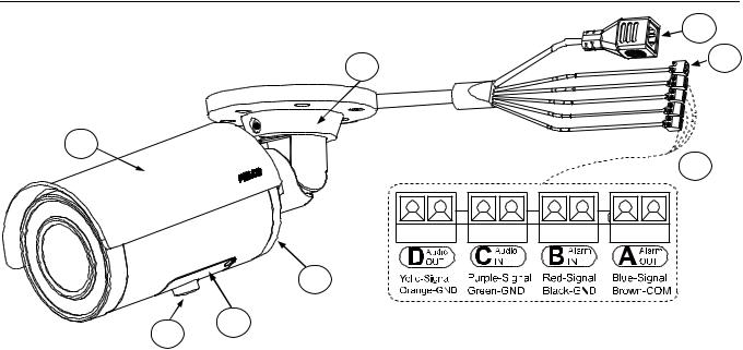
1.3 Physical Characteristics
|
3 |
6 |
4 |
|
2
5
1
8
7
FIGURE 1-2: CAMERA CONNECTIONS AND FEATURES 1/2
1.Camera Main Body
2.Sun Shield: Minimize the effects of rain and sunlight on image quality.
3.RJ-45 Network Port: Connects the camera to the IP network. Also supplies power to the camera through the network using PoE. If PoE is not available, the camera is required to be powered by 12 VDC or 24 VAC instead.
4.Power Connector (Black / Red): Connects to the external power source: DC12V or AC24V (refer to camera label).
5.Digital I/O Connectors
Alarm Out (Blue-Signal / Brown-COM): Using the “Signal” and “COM” ports, connect to an external device to be triggered through alarm output signals.
Alarm In (Red-Signal / Black-GND): Using the “Signal” and “GND” ports, connect to an external device that can trigger alarm input signals.
Audio In (Purple-Signal / Green-GND): Using the “Signal” and “GND“ ports, connect to an external device like a microphone that receives sound for camera.
Audio Out (Yellow-Signal / Orange-GND): Using the “Signal” and “GND“ ports, connect to an external device like a speaker that transmits audio sounds.
6.Mount Bracket: Install the camera to wall or ceiling.
7.Tripod Mount Screw Hole: Reserved for Tripod installation.
8.Metal Cover: Loosen the two screws and remove the metal cover. The interior buttons and interfaces will appear as the following figure shown.
10
1
2
5
3
4
FIGURE 1-3: CAMERA CONNECTIONS AND FEATURES 2/2
1.Micro SD Card Slot (Micro SD): Insert a micro SD card to the slot for recording and storage.
2.Reset Button (R): Using a small tool, such as a paper clip, hold down the reset button within 5 seconds and release to restart the camera.
3.Default (DEFAULT): Using a small tool, such as a paper clip, hold down the reset button longer than 5 seconds to reset the camera to factory defaults.
4.Ethernet/PoE: The port in the middle has already connected to a POE cable. The other end of the cable is a RJ-45 Network Port. Connects the camera to the IP network and the LED indicators will light on.
5.Action (ACT) & Link (LINK): LED indicators. The LED indicators show the status as the list below:
Color |
|
|
Status |
|
|
Indication |
|
Green |
|
|
On |
|
|
Network connection is established. |
|
|
|
|
|
|
|
|
|
|
|
Off |
|
|
No network connection. |
|
|
|
|
|
|
|
|
||
|
|
|
|
|
|
|
|
|
|
|
Blinking |
|
|
Networking is active |
|
|
|
|
|
|
|
|
|
Orange |
|
|
On |
|
|
Collision occurs |
|
|
|
|
|
|
|
|
|
|
|
|
Off |
|
|
Networking is inactive |
|
|
|
|
|
|
|
|
|
11

2. Installation and Connection
2.1 Unpacking Everything
Check all items in the product box against the order form and the packing slip. In addition to this manual, the items below are included in the product box:
Environmental IR Bullet camera / Indoor Bullet camera * 1
Plastic Anchor * 4
Flat Head Screw (Tapping Type) * 4
T20 Security Torx Wrench * 1
Mounting Template * 1
Printed Quick Installation Guide * 1
Resource sheet * 1
Important Safety Instruction * 1
Please contact your dealer if any items are missing.
2.2 Optional Accessories
IBP2BBAP-ES: a Sarix Environmental Surface mount for Bullet
IBP2BBAP-EI: a Sarix Environmental In-Ceiling Mount for Bullet
2.3 Installation
Following tools might help you complete the installation:
A drill
Screwdrivers
Wire cutters
2.3.1 Checking Appearance
Although the protective materials used for the packaging should be able to protect the unit from most accidents during transportation, check the unit and its accessories for any visible damage. Remove the protective film to check items in accordance with the list in 2.1 Unpacking Everything.
12

2.3.2 Mounting & Wiring
2.3.3.1 Surface Installation - Ceiling or Wall
Step 1. Mounting Preparation
1.Place the supplied mounting template on a mounting surface. Drill 6 mm (0.25”) outer holes at the T1 or T2 template positions on the mounting surface. Then insert 4 or 2 supplied plastic anchors into the holes. (T1: for double-gang socket, T2: for single-gang socket, if applicable on mounting surface)
2.Please then hammer the corresponding plastic anchors (4 or 2) into the drilled holes on the mounting surface.
This section is the preserved area for cable entry space.
FIGURE 2 - 1: MOUNTING TEMPLATE
Step 2. Mounting the Camera
1.Position the camera to match the drilled holes embedded with the plastic anchors on the surface.
2.Secure the corresponding tapping screws (4 or 2) to fasten the camera with the mounting surface tightly.
Plastic Anchors
Tapping Screws
FIGURE 2 - 2: MOUNTING THE CAMERA
13

Step 3. Wiring the Camera
1.While mounting the camera, pass the PoE Port, power port and digital IO ports thread, which penetrate from the mounting bracket, through the hole of mounting surface or place it by the side hole of the mounting bracket as the following figures shown depending on your different applications.
2.Connect an Ethernet cable terminated with the RJ-45 connector with the PoE Port of the camera and make sure the other end of the Ethernet cable connects with a PoE compatible network device that supplies power with networking capability. Also, connect AC24V/DC12V power source wires to the power port and wire the digital ports with the alarm in/out, audio in/out cables that connect with external devices if necessary.
PoE Port
Digital IO Ports
Power Port
FIGURE 2 - 3: CONNECTING THE WIRES TYPE - BRACKET SIDE HOLE
FIGURE 2 - 4: CONNECTING THE WIRES TYPE – MOUNTING SURFACE HOLE
14
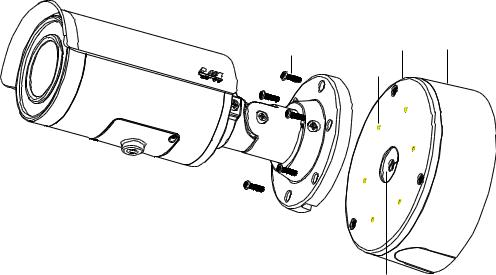
With IBP2BBAP-ES
Also, you can mount the camera to the wall with IBP2BBAP-ES, a Sarix Environmental Surface Mount for Bullet. Refer to
the figure below for surface installation with IBP2BB-ES.
1.Fix the IBP2BBAP-ES back box (#1) to the desirable surface by drilling three holes and fastening it with screws.
2.Pass all the signal cables through the hole of rubber (#5), and then insert the rubber into the center hole of metal plate.
NOTE: Please identify both sides of the rubber. The side of the rubber with the inclined angle must be towards the
terminals of the cables and metal plate to avoid water leakage.
3.Install the adaptor plate(#2) in the back box and tighten the screws
4.Insert screws (#4) through the bracket’s screw holes and tighten screws into the corresponding hole (#3) of the adaptor metal.
5.Complete surface installation with IBP2BBAP-ES.
|
|
|
|
|
|
FIGURE 2-5: SURFACE MOUNT WITH IBP2BBAP-ES
15
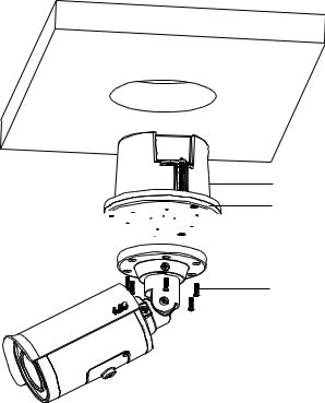
2.3.3.2 In-Ceiling Installation
The In-Ceiling Installation is mounting the camera into the ceiling with IBP2BBAP-EI, a Sarix Environmental In-Ceiling Mount for Bullet. Refer to the figure below for in-ceiling installation with IBP2BBAP-EI.
1.Make a round hole for IBP2BBAP-EI back box to fit in.
2.Pass all the signal cables through the hole of rubber (#5), and then insert the rubber into the center hole of metal plate.
NOTE: Please identify both sides of the rubber. The side of the rubber with the inclined angle must be towards the terminals of the cables and metal plate to avoid water leakage.
3.Install the adaptor plate(#2) in the back box and tighten the screws
4.Insert screws (#4) through the bracket’s screw holes and tighten screws into the corresponding hole (#3) of the adaptor metal.
5.Complete in-ceiling installation with IBP2BBAP-EI.


FIGURE 2-6: IN-CEILING INSTALLATION WITH IBP2BBAP-EI
16
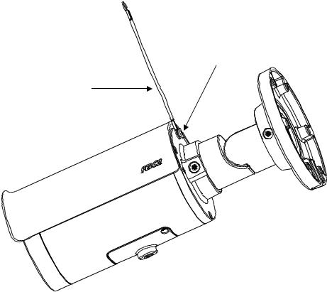
2.3.3 Safety Wire Preparation
If you possess a safety wire (fall prevention wire, not supplied), connect the safety wire with one end to the mounting surface and the other end to the safety-cord screw of the camera.
Safety Cord Screw
Safety Wire
FIGURE 2 - 7: SAFETY CORD INDICATION
NOTE: Depending on the material of mounting surface, different screws and anchors than those supplied may be required. To prevent the camera from falling off, ensure that it is mounted to a firm place using a safety wire strong enough to withstand the total weight of the camera. (Pay also attention to the finishing at the ends of the wire.)
17

2.3.4 Adjusting the Camera Position
Retaining Ring for Pan Adjustment (A)
Loosen the locking screw by T20 torx wrench and rotate the retaining ring (A) to adjust the camera horizontally for applying to a variety of applications.
Bracket Axis for Tilt Adjustment (B)
Loosen the locking screw by T20 torx wrench and tilt the bracket axis (B) to adjust the camera vertically for applying to varied applications.
Adjustable Ring for 360°Rotation (C)
Loosen the locking screw by T20 torx wrench and rotate the camera body (C) to adjust the camera for applying to varied applications.
C
B
A
FIGURE 2 - 8: ADJUSTING THE CAMERA POSITION
NOTE: After adjustments, make sure to tighten the each part for preventing camera from removing.
NOTE: Limitation for 3 axes position: Pan range: ±360°, Tilt range: 0° 90°, Rotation range: ±360°.
18
2.3.5 Adjusting the Focus
1.View the camera image using the browser (refer to 2.4 Connection page 22).
2.Use the settings in the Web interface (refer to
19
3.2.3.4 Focus on page 45) to adjust the zoom and focus of the lens to the desired field of view.
3.Also the focus can be adjusted b moving the zoom slider and using the Focus options in the live webpage.
NOTE: Focus adjustment is done exclusively with Web UI.
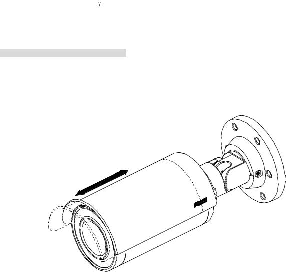
2.3.6 Adjusting the Protection Shield Hood
Environmental IR Series Exclusive Only
The environmental IR series are designed with capability to operate under rugged environments and therefore may be subject to influences from sunlight or rain. Protection shield hood is therefore coated on the camera to prevent damage from those outside effects. To adjust the protection shield hood, Move the hood forward or backward to adjust till the desired position based on your different applications.
FIGURE 2 - 9: ADJUSTING THE PROTECTION SHIELD HOOD
NOTE: Be sure to adjust the protection shield hood in accordance with the lens coverage in case of shadow problems occurring. To avoid housing damage, DO NOT adjust the protection shield hood position excessively.
20
2.3.7 Network Topology
The unit, which is equipped with Ethernet RJ-45 network interface, can deliver video images in real time via either Internet or Intranet. Please refer to the skeleton drawings shown to enhance your understanding.
FIGURE 2-10: NETWORK TOPOLOGY
21
 Loading...