


Peerless Industries PWV240-BK, PP740 User Manual

Installation and Assembly:
Paramount™ Pivot for 22" - 40" (56 - 102 cm) LCD screens
Models: PP740, PWV240/BK
Features:
• Fits 22" - 40" (56 - 102 cm) LCD screens
• Two tensionable pivot points for extensive adjustment of
viewing angle
®
• VESA
• Frees up space by folding flat against the wall
75/100/200 x 100/200 x 200 compatible
U
©
L
I
USC
D
2
:
6
0
7
0
8
0
1
0
0
Max Load Capacity: 80lb (36 kg)
ISSUED: 02-05-09 SHEET #: 202-9312-1

NOTE: Read entire instruction sheet before you start installation and assembly.
WARNING
• Do not begin to install your Peerless product until you have read and understood the instructions and warnings
contained in this Installation Sheet. If you have any questions regarding any of the instructions or warnings, for US
customers please call Peerless customer care at 1-800-865-2112, for all international customers, please contact
your local distributor.
• This product should only be installed by someone of good mechanical aptitude, has experience with basic building
construction, and fully understands these instructions.
• Make sure that the supporting surface will safely support the combined load of the equipment and all attached
hardware and components.
• Never exceed the Maximum Load Capacity. See page one.
• If mounting to wood wall studs, make sure that mounting screws are anchored into the center of the studs. Use of
an "edge to edge" stud finder is highly recommended.
• Always use an assistant or mechanical lifting equipment to safely lift and position equipment.
• Tighten screws firmly, but do not overtighten. Overtightening can damage the items, greatly reducing their holding
power.
• This product is intended for indoor use only. Use of this product outdoors could lead to product failure and personal
injury.
• This product was designed to be installed on the following wall construction only;
WALL CONSTRUCTION HARDWARE REQUIRED
• Wood Stud Included
• Wood Beam Included
• Solid Concrete Included
• Cinder Block Included
• Metal Stud Do not attach except with Peerless Metal Stud Accessory Kit - WSP490;
• Brick Contact Qualified Professional
• Other or unsure? Contact Qualified Professional
Tools Needed for Assembly
• stud finder ("edge to edge" stud finder is recommended)
• phillips screwdriver
• drill
• 5/16" (8 mm) bit for concrete and cinder block wall
• 5/32" (4 mm) bit for wood stud wall
• level
Table of Contents
Parts List.................................................................................................................................................................................3
Installation to Wood Stud Wall ................................................................................................................................................4
Installation to Solid Concrete and Cinder Block .....................................................................................................................5
®
Attaching Adapter Plate to Screen with VESA
Installing to Peerless LC or PLP Model Adapter Bracket .......................................................................................................8
Cord Management and Arm Tension Adjustment ................................................................................................................10
Mounting Pattern ..........................................................................................6
2 of 20
ISSUED: 02-05-09 SHEET #: 202-9312-1

Before you begin, make sure all parts shown are included with your product.
K
y
A
Parts List
Description
wall mount assembly
concrete anchor 2 590-0320
B
retaining spacer 4 590-5005
C
1/4-20 x 13 mm flat head phillips screw 2 520-1209
D
M4 x 10 mm phillips screw 4 504-9012
E
M4 x 20 mm phillips screw 4 504-9020
F
M6 x 12 mm phillips screw 4 520-1128
G
#14 x 63.5 mm flat head wood screw 2 520-1202
H
M6 x 20 mm phillips screw 4 520-9402
I
M6 x 30 mm phillips screw 4 510-9109
J
M5 x 6 mm phillips screw 5 520-1023
K
#10 flat washer 4 540-9400
L
hook bracket 1
M
adapter plate
N
#10-32 x 6 mm flat head phillips screw 1 520-1108
O
P cable tie 1 560-1725
Parts may appear slightly different than illustrated.
A
BE
PWV240/B
PP740
Part #
Qt
.
095-0545-GB
1
095-P1346
095-P1322
1
CF
D
G
M
H
IJ
NO
3 of 20
P
KL
ISSUED: 02-05-09 SHEET #: 202-9312-1
Installation to Wood Stud Wall
WARNING
• Installer must verify that the supporting surface will safely support the combined load of the equipment and all
attached hardware and components.
• Tighten wood screws so that wall plate is firmly attached, but do not overtighten. Overtightening can damage the
screws, greatly reducing their holding power.
• Never tighten in excess of 80 in. • lb (9 N.M.).
• Make sure that mounting screws are anchored into the center of the stud. The use of an "edge to edge" stud finder
is highly recommended.
• Hardware provided is for attachment of mount through standard thickness drywall or plaster into wood studs. Install-
ers are responsible to provide hardware for other types of mounting situations (not UL approved).
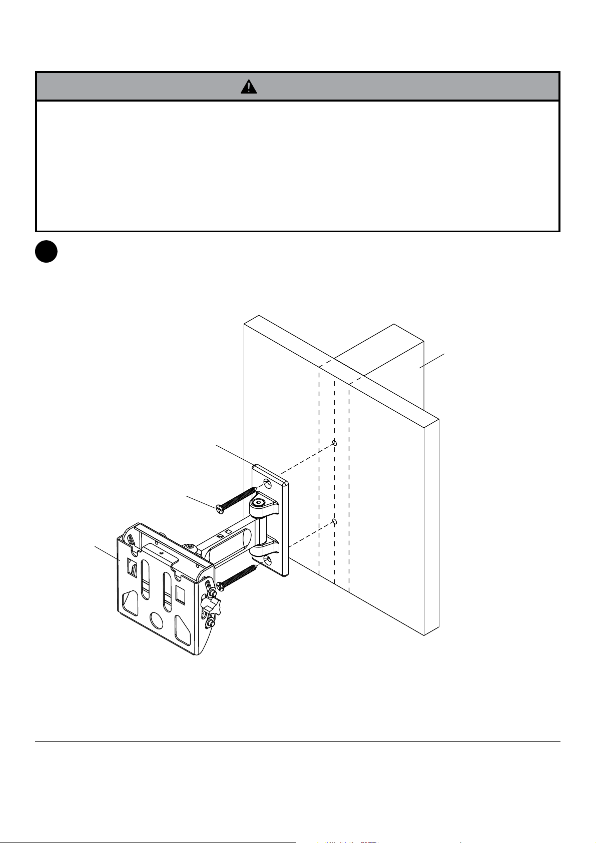
Using a stud finder, locate and mark the edges of the wood stud used in mounting this product. Use of an edge to
1
edge stud finder is highly recommended. Use a level to draw a vertical line down the center of the stud. Use wall
plate as template to mark center of holes along the vertical line. Drill two 5/32" (4 mm) dia. holes 2.5" (64 mm)
deep. Attach wall mount (A) to wall using two #14 x 63.5 mm flat head wood screws (H) as shown.
Skip to step 2 on page 6.
A
WOOD STUD WALL
WALL PLATE
H
4 of 20
ISSUED: 02-05-09 SHEET #: 202-9312-1

Installation to Solid Concrete and Cinder Block
WARNING
• When installing Peerless wall mounts on cinder block, verify that you have a minimum of 1-3/8" of actual concrete
thickness in the hole to be used for the concrete anchors. Do not drill into mortar joints! Be sure to mount in a
solid part of the block, generally 1" minimum from the side of the block. Cinder block must meet ASTM C-90
specifications. It is suggested that a standard electric drill on slow setting is used to drill the hole instead of a
hammer drill to avoid breaking out the back of the hole when entering a void or cavity.
• Concrete must be 2000 psi density minimum. Lighter density concrete may not hold concrete anchor.
• Make sure that the supporting surface will safely support the combined load of the equipment and all attached
hardware and components.
Level and use wall plate as template to mark center
1
of holes.
minimum depth of 2.5" (64 mm). Insert anchors (B)
in holes flush with wall. Place wall mount (A) over
anchors and secure with wood screws (H). Make
sure wall mount is level, and tighten all fasteners.
Drill two 5/16" (8 mm) dia. holes to a
1
B
Drill holes and insert anchors (B).
concrete
surface
WARNING
• Tighten screws so that wall plate is firmly attached,
but do not overtighten. Overtightening can damage
the screws, greatly reducing their holding power.
• Never tighten in excess of 80 in. • lb (9 N.M.).
WARNING
• Always attach concrete expansion anchors directly
to load-bearing concrete.
• Never attach concrete expansion anchors to
concrete covered with plaster, drywall, or other
finishing material. If mounting to concrete surfaces
covered with a finishing surface is unavoidable,
the finishing surface must be counterbored as
shown below. Be sure concrete anchors do not
pull away from concrete when tightening screws. If
plaster/drywall is thicker than 5/8" (16 mm), custom
fasteners must be supplied by installer.
INCORRECT CORRECT
wall
plate
concrete
wall
plate
concrete
2
A
H
Place plate (A) over anchors (B) and secure with screws (H).
3
Tighten all fasteners.
SOLID CONCRETE
CINDER BLOCK
B
WALL PLATE
B
CUTAWAY VIEW
plaster/
dry wall
plaster/
dry wall
5 of 20
H
A
ISSUED: 02-05-09 SHEET #: 202-9312-1

Attaching Adapter Plate to Screen with VESA® 200 x 100
or 200 x 200 Mounting Pattern
NOTE: For VESA 75 mm and 100 mm patterns, see following page.
Attach hook bracket (M) to adapter plate (N) using
2
four M5 x 6 mm screws (K) and #10 washers (L) as
shown.
M
N
L
K
WARNING
• If screws don't get three complete turns in the screen inserts or if screws bottom out and adapter plate is still not
tightly secured, damage may occur to screen or product may fail.
FOR VESA® 200 x 100 MOUNTING PATTERN:
Choose hole pattern as shown below. Attach
2-1
adapter plate (N) to back of screen using four M4 x
10 mm screws (E) as shown below.
*NOTE: If screw (E) gets less than three threads
of engagement, attach adapter plate (N) to back of
screen using four M4 x 20 mm screws (F) and four
spacers (C) as indicated below.
Skip to step 3 on page 9.
FOR VESA® 200 x 200 MOUNTING PATTERN:
Choose hole pattern as shown below. Attach adapter
plate (N) to back of screen using four M6 x 12 mm
screws (G) as shown below.
*NOTE: If screw (G) gets less than three threads
of engagement, attach adapter plate (N) to back of
screen using four M6 x 20 mm screws (I). If screw (I)
still gets less than three threads of engagement, use
four M6 x 30 mm screws (J).
Skip to step 3 on page 9.
E
*For screens with a
N
hole pattern in a pocket,
spacers (C) go between
adapter plate (N) and
screen.
C
6 of 20
G
N
ISSUED: 02-05-09 SHEET #: 202-9312-1
 Loading...