

PEERLESS Pinnacle PO-70, Pinnacle PO-70A, Pinnacle PO-84, Pinnacle PO-84A, Pinnacle Installation, Operation & Maintenance Manual
Page 1
Pinnacle
®
Boilers
Peerless
®
Oil
Installation,
Operation &
Maintenance
Manual
As an ENERGY STAR®Partner, PB Heat, LLC has determined that this
product meets the ENERGY STAR
®
guidelines for energy efficiency.
Page 2

USING THIS MANUAL 1
A. INSTALLATION SEQUENCE . . . . . . . . . . . . .1
B. SPECIAL ATTENTION BOXES . . . . . . . . . . . .1
1. PREINSTALLATION 2
A. GENERAL . . . . . . . . . . . . . . . . . . . . . . . . . . . .2
B. CODES & REGULATIONS . . . . . . . . . . . . . . .2
C. ACCESSIBILITY CLEARANCES . . . . . . . . . . .2
D. COMBUSTION & VENTILATION AIR . . . . . . .2
E. PLANNING THE LAYOUT . . . . . . . . . . . . . . . .3
2. BOILER SET-UP 4
A. GENERAL . . . . . . . . . . . . . . . . . . . . . . . . . . . .4
3. VENTING, INLET AIR & CONDENSATE 5
A. GENERAL . . . . . . . . . . . . . . . . . . . . . . . . . . . .5
B. APPROVED MATERIALS FOR EXHAUST
VENT AND INLET AIR PIPING . . . . . . . . . . . .5
C. EXHAUST VENT/INLET AIR LOCATION . . . .5
D. CONCENTRIC VENTING SYSTEM . . . . . . . .6
E. EXHAUST VENT AND AIR INLET PIPE
INSTALLATION . . . . . . . . . . . . . . . . . . . . . . . .6
F. STANDARD VENT KITS . . . . . . . . . . . . . . . . .7
G. CONDENSATE . . . . . . . . . . . . . . . . . . . . . . . .8
4. WATER PIPING 10
A. GENERAL . . . . . . . . . . . . . . . . . . . . . . . . . . .10
B. SYSTEM COMPONENTS . . . . . . . . . . . . . . .10
C. SYSTEM PIPING . . . . . . . . . . . . . . . . . . . . . .12
D. FREEZE PROTECTION . . . . . . . . . . . . . . . . .12
E. SPECIAL APPLICATIONS . . . . . . . . . . . . . . .18
5. OIL BURNER INSTALLATION 20
A. GENERAL . . . . . . . . . . . . . . . . . . . . . . . . . . .20
B. BURNER INSTALLATION . . . . . . . . . . . . . . .20
6. ELECTRICAL & CONTROLS 21
A. GENERAL . . . . . . . . . . . . . . . . . . . . . . . . . . .21
B. BURNER WIRING . . . . . . . . . . . . . . . . . . . . .21
C. BOILER WIRING . . . . . . . . . . . . . . . . . . . . . .21
D. CONTROL TERMS . . . . . . . . . . . . . . . . . . . .22
E. SEQUENCE OF OPERATION . . . . . . . . . . . .23
F. BOILER SAFETY INTERLOCKS . . . . . . . . . .24
G. BOILER TEMPERATURE CONTROL
OPTIONS . . . . . . . . . . . . . . . . . . . . . . . . . . .24
H. CONTROL MODES . . . . . . . . . . . . . . . . . . . .24
I. USER INTERFACE . . . . . . . . . . . . . . . . . . . .24
J. CONTROL ACCESS LEVELS . . . . . . . . . . . .25
K. TROUBLESHOOTING . . . . . . . . . . . . . . . . . .27
L. POC TECHNICAL DATA . . . . . . . . . . . . . . . .28
7. START-UP PROCEDURE 30
A. GENERAL . . . . . . . . . . . . . . . . . . . . . . . . . . .30
B. FILL THE SYSTEM WITH WATER . . . . . . . .30
C. CHECK THE ELECTRIC CIRCUITS . . . . . . . .30
D. PRIME THE FUEL UNIT . . . . . . . . . . . . . . . .30
E. SET COMBUSTION . . . . . . . . . . . . . . . . . . .30
F. CHECK BOILER FUNCTION . . . . . . . . . . . . . .31
8. TROUBLESHOOTING 32
A. GENERAL . . . . . . . . . . . . . . . . . . . . . . . . . . .32
9. MAINTENANCE 34
A. GENERAL MAINTENANCE (WITH BOILER
IN USE) . . . . . . . . . . . . . . . . . . . . . . . . . . . . .34
B. ANNUAL MAINTENANCE (BEFORE THE
START OF HEATING SEASON) . . . . . . . . . .34
10. BOILER DIMENSIONS & RATINGS 37
A. BOILER DIMENSIONS . . . . . . . . . . . . . . . . .37
B. BOILER RATINGS . . . . . . . . . . . . . . . . . . . . .37
11. REPAIR PARTS & OPTIONAL
ACCESSORIES 38
TABLE OF CONTENTS
TABLE OF CONTENTS
Page 3

A. INSTALLATION SEQUENCE
Follow the installation instructions provided in this manual
in the order shown. The order of these instructions has
been set in order to provide the installer with a logical
sequence of steps that will minimize potential
interferences and maximize safety during boiler
installation.
B. SPECIAL ATTENTION BOXES
Throughout this manual special attention boxes are
provided to supplement the instructions and make special
notice of potential hazards. The definition of each of
these categories, in the judgement of PB Heat, LLC
are as follows:
USING THIS MANUAL
Indicates special attention is needed, but not directly
related to potential personal injury or property
damage.
NOTICE
Indicates a condition or hazard which will or can
cause minor personal injury or property damage.
CAUTION
DANGER
Indicates a condition or hazard which will cause
severe personal injury, death or major property
damage.
Indicates a condition or hazard which may cause
severe personal injury, death or major property
damage.
WARNING
1
USING THIS MANUAL
Page 4

2
A. GENERAL
1. Pinnacle Oil boilers are supplied factory assembled
with pressure vessel, base, and jacket panels. A trim
box containing the relief valve, drain valve,
temperature / pressure gauge and associated pipe
fittings is included in the crate.
2. The burner, acoustic shroud and venting are shipped
separately for field assembly. The POC control is
shipped separately for maximum flexibility.
3. The package should be carefully inspected for damage
upon receipt and any damage to the unit should be
reported to the shipping company and wholesale
distributor.
4. The boiler should be stored in a clean, dry location.
5. Carefully read these instructions and be sure to
understand the functions of all mechanical and
electrical connections before beginning the
installation. Contact your PB Heat, LLC
representative for help in answering questions.
6. This boiler must be installed by a qualified contractor.
The boiler warranty may be voided if the boiler is not
installed correctly.
7. This boiler may be installed at high altitudes above
5,000 feet elevation. Consult burner manual
(included) for burner requirements.
B. CODES & REGULATIONS
1. Installation and repairs are to be performed in strict
accordance with the requirements of state and local
regulating agencies and codes dealing with boiler and
appliance installation.
2. In absence of local requirements the following codes
and standards should be followed.
a) ASME Boiler & Pressure Vessel Code, Section IV –
Heating Boilers
b) ASME Boiler & Pressure Vessel Code, Section VI –
Recommended Rules for the Care and Operation
of Heating Boilers.
c) ANSI/NFPA 70 – National Electrical Code
d) NFPA 31 – Standard for the Installation of Oil-
Burning Equipment.
e) ANSI/NFPA 211 – Chimneys, Fireplaces, Vents
and Solid Fuel Burning Appliances.
3. Where required by the authority having jurisdiction,
the installation of this equipment must comply with
ANSI/ASME CSD-1 – Standard for Controls and
Safety Devices for Automatically Fired Boilers.
C. ACCESSIBILITY CLEARANCES
1. The Pinnacle Oil boiler is design certified for closet
installations with zero clearance to combustible
construction. In addition, it is certified for use on
combustible floors provided the boiler is not installed
on carpeting.
2. Refer to Figure 1.1 for the recommended clearances
to allow for reasonable access to the boiler. Local
codes or special conditions may require greater
clearances.
D. COMBUSTION & VENTILATION AIR
1. The Pinnacle Oil boiler is designed for several options
for combustion air and venting.
a) Concentric Sidewall Venting
b) Concentric Vertical Chimney Venting
c) Single Wall Vertical Chimney Venting using the
chimney as a chase for inlet air.
d) Concentric Vertical Roof Venting
2. The concentric venting options are designed for
operation with combustion air piped from the outside
(sealed combustion). For these options, no additional
ventilation air is required.
PREINSTALLATION
1. PREINSTALLATION
This appliance must be supplied with adequate
combustion air to properly burn the fuel. Failure to
supply an adequate air supply will result in
incomplete combustion resulting in sooting and
carbon monoxide emission. This may result in severe
personal injury, death or major property damage.
WARNING
DANGER
Do not install this boiler on carpeting.
Page 5
3
E. PLANNING THE LAYOUT
1. Prepare sketches and notes showing the layout of the
boiler installation to minimize the possibility of
interferences with new or existing equipment, piping,
venting and wiring.
2. Review the following sections of this manual for
consideration of the limitations with respect to:
a) Venting: Section 3
b) Air Intake Piping: Section 3
c) Condensate Removal: Section 3
d) Water Piping: Section 4
e) Oil Burner & Fuel Piping: Section 5
f) Electric and Controls: Section 6
PREINSTALLATION
This appliance is certified as an indoor appliance. Do
not install this boiler outdoors or locate where it will
be exposed to freezing temperatures.
WARNING
Do not install this boiler where gasoline or other
flammable liquids or vapors are stored or are in use.
WARNING
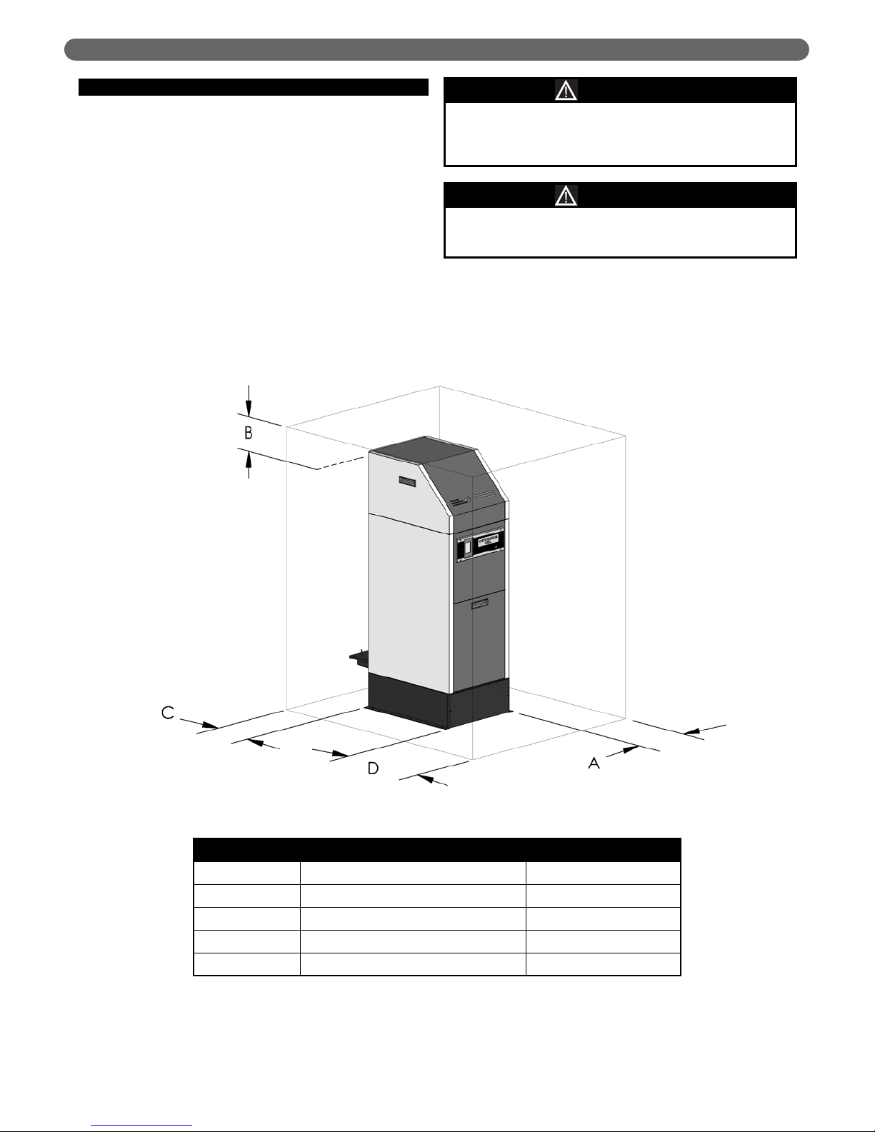
Service Clearances
Designation Description Dimension
“A” Burner Swing Clearance (Left or Right) 16" [406 mm]
“B” Jet/Acoustic Shroud Removal Clearance 13" [330 mm]
“C” Vent/Air Intake Sampling Clearance 12" [305 mm]
“D” Control Panel Access Clearance 24" [610 mm]
Figure 1.1: Recommended Service Clearances
Page 6

4
A. GENERAL
1. Pinnacle Oil boilers are to be installed in either an
area with a floor drain or in a suitable drain pan.
Do not install any boiler where leaks or relief valve
discharge will cause property damage.
2. This boiler is not intended to support external piping.
All venting and other piping should be supported
independently of the boiler.
3. Provide a level foundation, located as close as
practicable to the center of the heating system.
4. After removing the boiler from the packaging and
setting it on its foundation, open the burner swing
door on the top of the boiler and make sure the jet
inserts are seated properly in the combustion
chamber. Refer to the repair parts in Section 11 to
identify these parts. Close the burner swing door
before continuing.
5. Install the boiler level to prevent condensation from
blocking the vent system.
BOILER SET-UP
2. BOILER SET-UP
Be sure that any packing material that is in the
combustion chamber to protect the Jet Inserts is
removed before firing the appliance. Failure to do
this may result in minor personal injury or property
damage.
CAUTION
Page 7

5
A. GENERAL
1. All venting and air inlet piping is to be installed in
accordance with local building codes, NFPA 31 and
these instructions.
2. This appliance may be vented in any one of the
following three ways. Examples of these systems are
detailed in this section.
a) Concentric Sidewall Venting
b) Concentric Vertical Chimney Venting
c) Single Wall Vertical Chimney Venting using the
chimney as a chase for inlet air
d) Concentric Vertical Roof Venting
B. APPROVED MATERIALS FOR EXHAUST
VENT AND INLET AIR PIPING
1. The venting system for this boiler has been approved
under UL-726 for use with this boiler. No substitutions
are to be made for this material.
2. The venting components shown in Table 3.2 and the
venting kits shown in Figures 3.2 through 3.5 are to
be purchased separately from your distributor.
Questions regarding the proper vent material are to be
directed to your PB Heat, LLC representative.
C. EXHAUST VENT/INLET AIR LOCATION
1. The concentric vent piping for this boiler is approved
for zero clearance to combustible construction.
2. The Pinnacle Oil boiler, like all high efficiency
products, is likely to produce a visible vapor plume
due to condensation. Surfaces near the vent
termination will likely be coated with condensation.
3. Care must be taken to locate the exhaust vent where
the exhaust gas, vapor plume, and condensation do
not cause a hazard or nuisance. For example, do not
locate the exhaust vent termination under a deck
where, under certain conditions, it could form a
coating of ice causing a hazard or reduce the life of
the deck materials.
4. Sidewall Vent System
a) Sidewall vented products are susceptible to wind
conditions that can effect combustion. To minimize
the effects of wind, the exhaust and air inlet
terminations must penetrate the same wall or
vertical surface. In addition, the length of the
exhaust and air inlet pipes must be roughly
equivalent.
b) Condensation from a sidewall vented appliance
may cause paint and other surface coatings to
deteriorate. In addition, soot stains may appear on
surrounding surfaces if the boiler is not properly
maintained.
c) If the boiler is used to heat potable (tap) water, the
boiler will operate year round. The effects of hot
gases and odors must be taken into consideration
during the summer months.
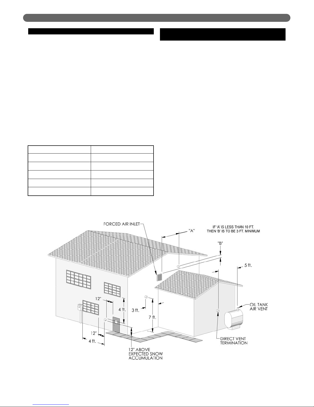
d) See Figure 3.1 for an illustration of clearances for
location of exit terminals for direct-vent, sidewall
venting systems.
e) The boiler vent system shall terminate at least 3
feet (0.9 m) above any forced air inlet located
within 10 feet (3 m). Note: This does not apply to
the combustion air inlet of a direct-vent appliance.
f) Provide a minimum of 1 foot (300 mm) distance
from any door, operable window, or gravity air
inlet into any building.
g) Do not locate the exhaust termination directly
under an operable window.
h) Provide a minimum of 1 foot (300 mm) clearance
from the bottom of the exhaust termination above
the expected snow accumulation level. Snow
removal may be necessary to maintain clearance.
i) Provide 4 feet horizontal clearance from electrical
meters, gas meters, air conditioning condensers or
other external equipment. In no case shall the exit
terminal be above or below the aforementioned
equipment unless a 4 foot horizontal distance is
maintained.
j) Do not locate the exit termination over public
walkways where condensate could drip or freeze,
causing a hazard or nuisance.
k) When the exhaust termination is adjacent to a
public walkway, it is to be located at least 7 feet
(2100 mm) above grade.
l) Do not locate exhaust termination directly under
roof overhangs to prevent icicles from forming.
m) Provide 3 feet (0.9 m) clearance from the inside
corner of adjacent walls.
VENTING, INLET AIR & CONDENSATE
3. VENTING, INLET AIR & CONDENSATE
DANGER
This vent system operates under a positive pressure.
Do not connect vent connectors serving appliances
vented by natural draft into any portion of
mechanical draft systems operating under positive
pressure. Failure to comply will result in severe
personal injury, death or major property damage.
Page 8
6
D. CONCENTRIC VENTING SYSTEM
1. The concentric venting system used with this
appliance consists of an inner pipe constructed of
polypropylene or stainless steel and an outer pipe
made of aluminum.
2. The inner pipe provides a path for the exhaust gases
to exit the boiler to the outdoors while space between
the pipes allows outdoor air to be conveyed to the
boiler.
3. The minimum vent length is 14 equivalent feet for
models PO-70 and PO-84 and 25 feet for models
PO-70A and PO-84A. This minimum length is
required to obtain the efficiency rating of this product.
The maximum vent length is 80 equivalent feet. Since
the air inlet pipe is integral to the vent, the same
minimum and maximum vent lengths apply.
4. The following chart gives equivalent lengths for
several common venting components.
E. EXHAUST VENT AND AIR INLET PIPE
INSTALLATION
1. Only polypropylene vent material supplied by PB
Heat, LLC is to be used with this appliance.
2. Horizontal lengths of vent pipe must slope towards the
boiler at a pitch not less than 1/4" per foot (20 mm
per meter) to allow condensate to drain from the vent
pipe into the boiler. If the vent pipe must be piped
around an obstacle that causes a low point in the
pipe, a drain pipe must be connected to this low point
to provide drainage.
3. All piping must be fully supported. Use pipe hangers
at a minimum of 4 foot (1.2 meter) intervals to
prevent sagging of the vent pipe where condensate
may form.
4. Do not use the boiler to support any piping. All piping
is to be supported externally.
VENTING, INLET AIR & CONDENSATE
Fitting Description Equivalent Length
Elbow, 90° 5
Cleanout Tee 5
Elbow, 45° 3
Vertical Vent Termination 0
Sidewall Vent Termination 0
Figure 3.1: Location of Exit Terminals of Mechanical Draft and Direct-Venting Systems
Page 9
7
F. STANDARD VENT KITS
1. Common Vent Kit (54044): The common vent kit
is required for each Pinnacle Oil Boiler. This includes:
a) (54000) Concentric Sample Port Adapter
b) (54001) Concentric Clean-out Tee
c) (54006) Adjustable Length Vent Pipe - 19-1/2"
Max.
d) (54002) Concentric 90° Support Elbow
e) (54048) Vent Pipe Support
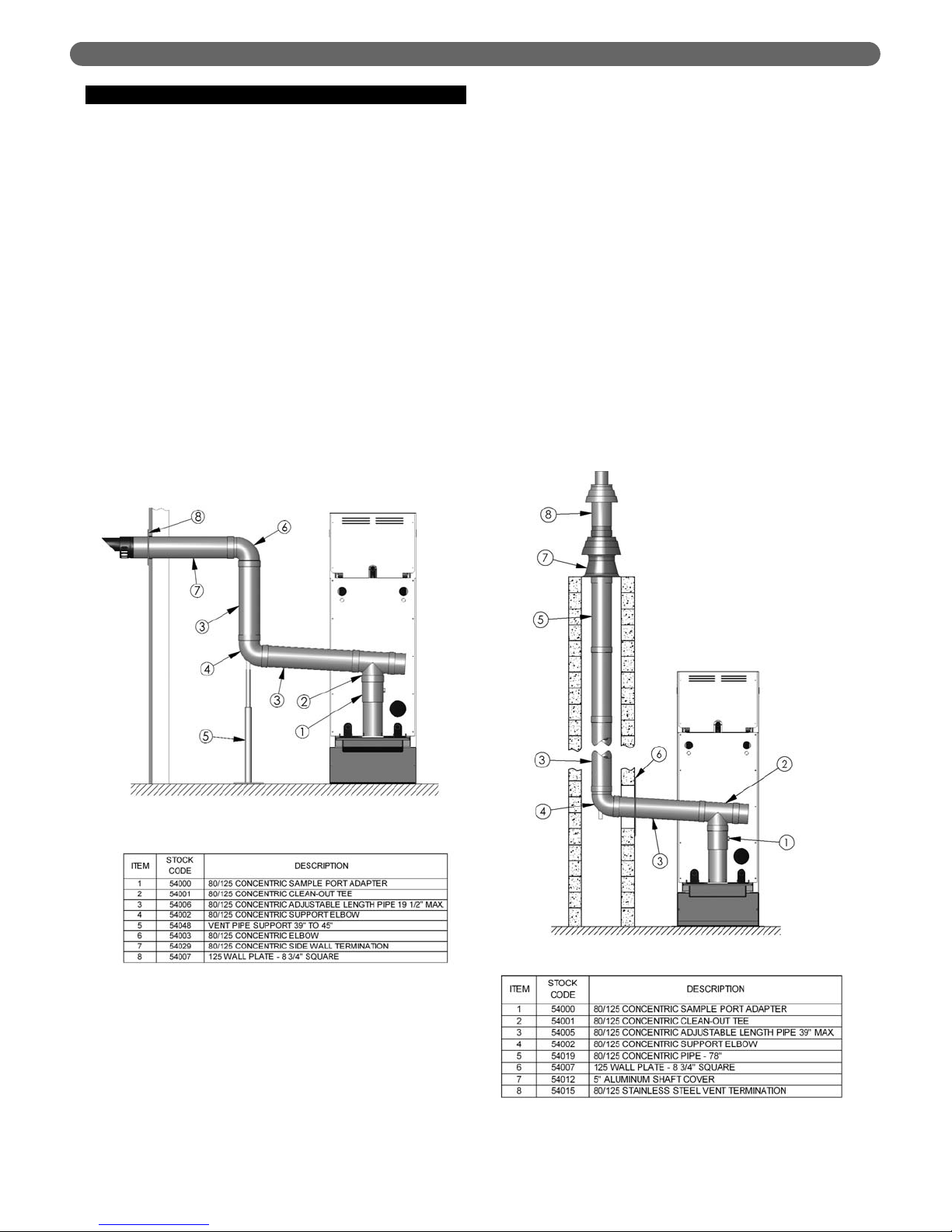
2. Concentric Sidewall Vent Kit (54045): A
concentric sidewall vent kit is used for boilers that are
vented through a building wall. This type of
installation is shown in Figure 3.2. This kit includes:
a) (54029) Concentric Sidewall Termination
b) (54003) Concentric 90° Elbow
c) (54007) Concentric Wall Plate
Additional vent pipe and fittings may be required to
complete the installation. Refer to the component list
for vent pipe in Table 3.2.
3. Concentric Vertical Chimney Vent Kit (54047):
A concentric vertical chimney vent kit is used to pipe
both the exhaust vent and the inlet air through an
existing chimney. An example of this type of
installation is shown in Figure 3.3. This kit includes:
a) (54012) Aluminum Shaft Cover Assembly
b) (54015) Vertical Vent Termination
Additional concentric vent pipe components may be
required to complete the installation. Refer to the
component list for vent pipe in Table 3.2.
4. Single Wall Vertical Chimney Vent Kit (54046):
A single wall vertical chimney vent kit is used to pipe
the exhaust vent through an existing chimney while
drawing the inlet air down through the chimney
around the exhaust vent pipe. An example of this type
of installation is shown in Figure 3.4. This kit includes:
a) (54036) Stainless Steel End Pipe
b) (54013) Aluminum Shaft Cover
Additional vent pipe components may be required to
complete the installation. Refer to the component list
for vent pipe in Table 3.2.
VENTING, INLET AIR & CONDENSATE
Figure 3.2: Sidewall Venting
Figure 3.3: Concentric Vertical Chimney Venting
Page 10
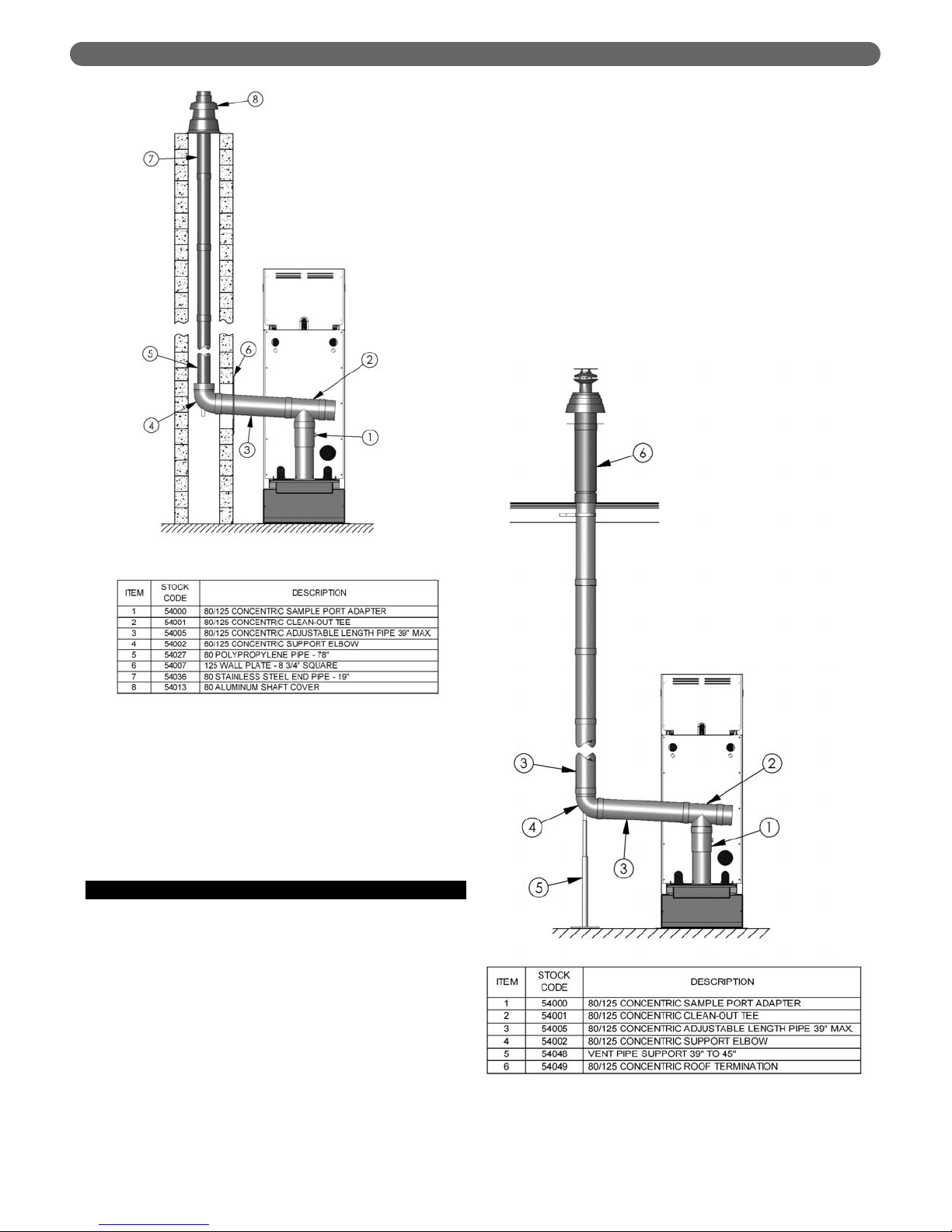
5. Concentric Vertical Roof Vent Kit (54049): The
concentric vertical roof vent kit is used without a
chimney to vent through the building roof. This type
of installation is shown in Figure 3.5. Additional
concentric vent pipe components may be required to
complete the installation. Refer to the component list
for vent pipe in Table 3.2.
G. CONDENSATE
1. The disposal of all condensate into public sewage
systems is to be in accordance with local codes and
regulations. In the absence of such codes, follow these
instructions.
2. The condensate from oil-fired condensing appliances
may have a pH value as low as 2. Some local codes
require the use of neutralization equipment to treat the
condensate.
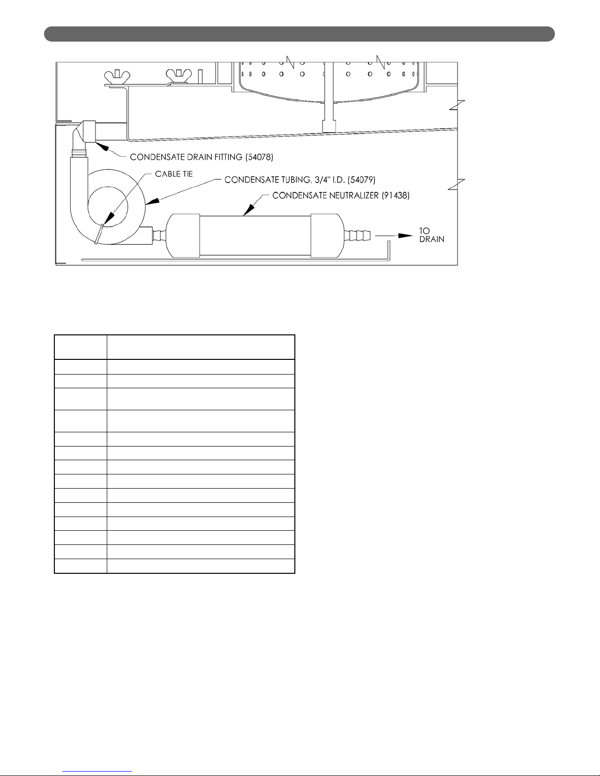
3. A condensate neutralizer (91438), available from your
distributor is recommended to reduce the acidity of
the condensate before it is piped to a drain.
4. This appliance must be fitted with a condensate trap
to prevent flue gas leakage.
5. Figure 3.6 shows a simple condensate trap that can
be utilized with this equipment. A 3/4" Female NPT x
3/4" O.D. Barb Adapter is used to attach a 3/4" ID
PVC (Tygon) Hose.
6. If the condensate outlet of the Pinnacle boiler is below
the drain level, a condensate pump must be used.
7. All piping for the condensate drain should be
corrosion resistant material such as PVC or
polypropylene. Do not use galvanized, aluminized, or
materials containing copper (such as brass or bronze)
for pipe or fittings.
8
VENTING, INLET AIR & CONDENSATE
Figure 3.4: Single Wall Vertical Chimney Venting
Figure 3.5: Concentric Vertical Roof Venting
Page 11
9
VENTING, INLET AIR & CONDENSATE
Figure 3.6: Condensate Trap & Neutralization
Table 3.2: Vent Pipe Component List
Stock
Code
Description
54017 Concentric Vent Pipe 19" Long
54018 Concentric Vent Pipe 39" Long
54006
Adjustable Length Concentric Vent Pipe - 19-1/2"
Maximum Length
54005
Adjustable Length Concentric Vent Pipe - 39"
Maximum Length
54003 90° Concentric Elbow
54062 Wall Clamp for Concentric Vent Pipe
54063 Universal Lead Tile for Vertical Vent Termination
54064 Flat Roof Flashing for Vertical Vent Termination
54024 9" Polypropylene Vent Pipe
54025 19" Polypropylene Vent Pipe
54026 39" Polypropylene Vent Pipe
54027 78" Polypropylene Vent Pipe
54023 90° Polypropylene Elbow
54058 45° Polypropylene Elbow
Page 12
10
A. GENERAL
1. All boiler piping is to be installed in accordance with
local building codes and these instructions.
2. This appliance is to be installed so that the electrical
components of the burner and ignition system are
protected from water (dripping, spraying, etc.) during
operation and service. Service includes circulator
replacement, condensate system cleaning, control
replacement and other general maintenance
procedures.
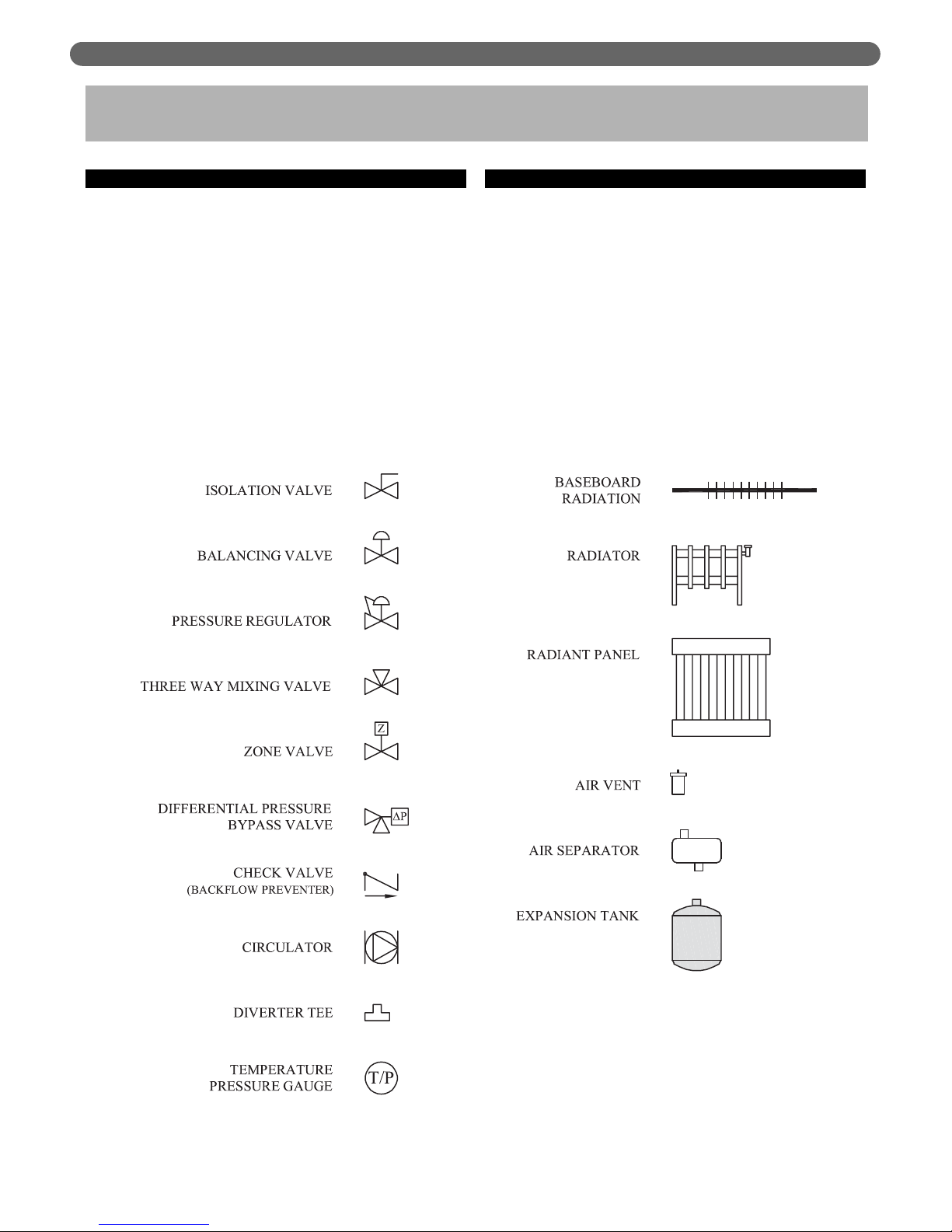
B. SYSTEM COMPONENTS
Figure 4.1 shows the symbol key for piping diagrams in
this section. The following are brief descriptions of system
components.
1. Pressure/Temperature Gauge: A combination
pressure/temperature gauge is provided with the unit
to be mounted in the piping from the boiler supply to
the system. Installation of this gauge is required by
most local codes.
WATER PIPING
4. WATER PIPING
Figure 4.1
Page 13
11
2. Air Elimination: Any closed-loop hydronic system in
which a Pinnacle Oil boiler is installed must have an
air elimination device. As the system water is heated,
dissolved oxygen, carbon dioxide and nitrogen gases
will separate from the liquid. An air elimination device
(such as a TACO 430 Series Air Scoop with an
automatic air vent) is required to remove the dissolved
gasses from the system preventing corrosion in the
piping system and eliminating system noise.
3. Expansion Tank: An expansion tank (such as a Bell &
Gossett Series HFT) is required to provide room for
expansion of the heating medium (water or glycol
solution). Consult expansion tank manufacturer’s
instructions for specific information regarding
installation. The expansion tank is to be sized for the
required system volume and capacity. In addition, be
sure that the expansion tank is sized for the proper
heating medium. Glycol solutions may expand more
than water for a given temperature rise.
4. Y-Type Strainer: In older heating systems where a
significant amount of sediment may be present, it may
be necessary to install a Y-type strainer. The strainer
should be checked and cleaned often in the first few
months of operation to assure that sediment does not
build up in the heat exchanger.
5. Flow Control Valve: Flow control valves such as the
Taco Flo-Check or Bell & Gossett Flo-Control are
used to prevent gravity circulation by incorporating a
check valve with a weighted disc.
6. Pressure Reducing Valve: A pressure reducing valve
such as the Bell & Gossett B-38 or Taco #329 is used
in a hydronic system to automatically feed water to
the system whenever pressure in the system drops
below the pressure setting of the valve. These valves
should not be used in glycol solution systems unless
the glycol concentration is closely monitored.
7. Back Flow Preventer: A back flow preventer is
required in some jurisdictions to prevent hydronic
system water from backing up into the potable water
supply. This is especially important on systems in
which glycol solution is used as the heating medium.
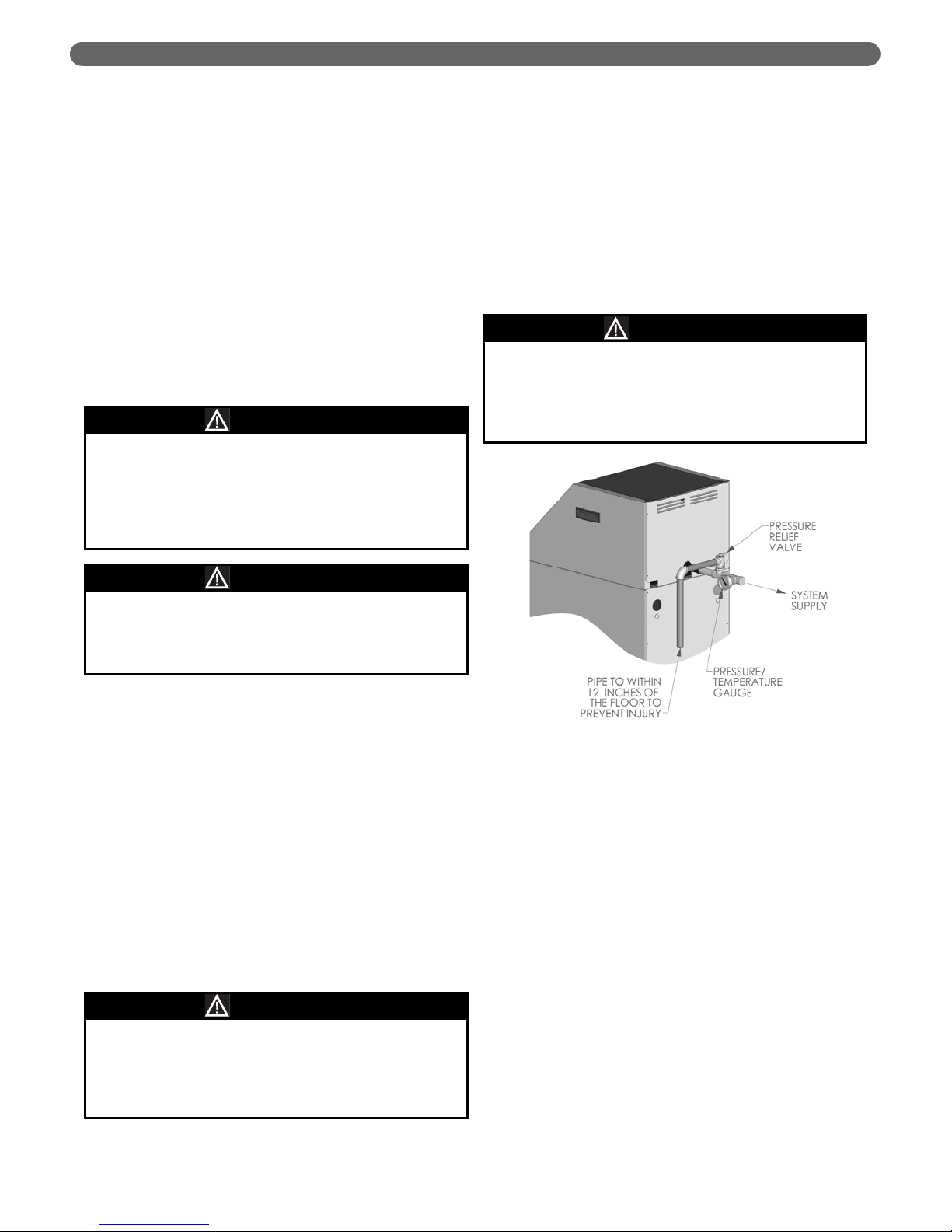
8. Pressure Relief Valve: A pressure relief valve is
supplied with each boiler for installation in the supply
piping. Figure 4.2 shows the installation of the
pressure relief valve and the temperature/pressure
gauge. The relief valve discharge is to be piped within
12” (305mm) of the floor and close to a floor drain.
Provide piping that is the same size or larger than the
relief valve outlet.
9. Isolation Valve: Isolation valves are intended to
provide a positive shut-off for isolating sections of
system piping. Ball valves and gate valves are
examples of valves for this purpose. These types of
valves are not intended for throttling flow.
10. Balancing Valve: Balancing valves are intended to
throttle water flow. Examples of this type of valve are
globe and needle valves.
11. Zone Valve: Zone valves are electronically activated
valves intended for use with zone thermostats to
provide heat only in the zone in which it is required.
12. Differential Bypass Valve: A differential bypass valve is
used to allow minimum circulation in a system
employing zone valves if all the zone valves close
before the circulator stops. This prevents the circulator
from “dead heading.”
13. Circulator: The boiler circulator is to be sized to
overcome the pressure drop of the system while
providing the flow required by the boiler.
WATER PIPING
Use only inhibited propylene glycol solutions which
are specifically formulated for hydronic systems.
Unlike automotive antifreeze, solutions for hydronic
applications contain corrosion inhibitors that will
protect the system components from premature
failure due to corrosion.
CAUTION
Pipe the discharge of the relief valve as close as
possible to the floor and away from high traffic areas.
Pipe the discharge close to a floor drain. Failure to
do so may result in serious personal injury and/or
property damage.
CAUTION
Use only inhibited propylene glycol solutions which
are specifically formulated for hydronic systems.
Ethylene glycol is toxic and may cause an
environmental hazard if a leak or spill occurs.
WARNING
Figure 4.2
Valves which automatically feed water under low
water conditions can allow leaks to go unnoticed.
This may allow large amounts of fresh water to be
added to the system resulting in scaling in the boiler
heat exchanger or dilution of glycol solutions.
NOTICE
Page 14

12
a) If the boiler is piped in a secondary loop of a
primary/secondary heating system, the circulator
will need only to overcome the resistance of the
boiler and any fittings in that loop. In the case of
the Pinnacle Oil boiler, the pressure drop through
the boiler is nearly negligible.
b) The circulator should be sized based on the boiler
net output. The boiler “Net I=B=R Output” for
each Pinnacle Oil Model is listed in the chart
below. This value includes a piping pickup factor
of 1.15.
c) The required flow rate can be calculated based on
the design temperature difference from the return
to the supply of the boiler. For a PO-50 with a
design water temperature rise of 20°F the
calculation is as follows:
d) The pressure drop of the system then determines
the circulator that should be used.
e) Special consideration must be given if propylene
glycol solution is to be used as a heating medium.
- Propylene glycol has a higher viscosity than
water; therefore the system pressure drop will
be higher.
- Propylene glycol has a lower heating capacity
than water and therefore requires a higher flow
rate (14% for a 50% glycol solution) to transfer
heat similar to water.
14. Indirect Water Heater: An indirect water heater,
such as the Peerless Partner, should be piped into
a dedicated zone. It consists of a water tank that
is heated by boiler water passing through an
internal coil.
C. SYSTEM PIPING
1. Figure 4.3: This illustration shows a single Pinnacle Oil
Boiler, a Peerless Partner Indirect Water Heater, and a
single heating zone.
a) The standard POC #1 control will accept separate
inputs for heating and hot water. This will allow
the heating zone to be supplied with a variable
temperature depending on outdoor temperature
(outdoor reset) while the domestic hot water zone
will have a pre-designated set point. A complete
description of this control will be given in Section
6 of this manual, Electrical & Controls. Note:
Outdoor reset operation requires an optional
Outdoor Sensor (54034).
b) By upgrading to the POC #2 control (54031), the
boiler may give domestic hot water full priority
over the heat load.
2. Figure 4.4: This diagram shows an additional zone in
which baseboard radiation is the heat load. Baseboard
radiation can be operated using the outdoor reset
function to maximize the boiler efficiency.
3. Figure 4.5: This figure shows diverter tees used in
combination with conventional hydronic radiators on
an additional zone.
a) Also, a second boiler is shown piped in parallel
with the first. It is important that the common
headers are sized to match the system piping.
Smaller headers may result in flow fluctuations
through the boilers.
b) An upgrade to the POC #3 control (54032) allows
a second boiler with a POC #1 conrol to act as a
second stage, firing only when the first boiler fails
to meet the load demand.
4. Figure 4.6: This illustration shows two boilers piped in
parallel feeding a primary/secondary system with 5
zones using zone circulators. In this configuration, the
supply water temperatures become increasingly cooler
when all zones are calling. Therefore, the hottest and
smallest zones should be piped closest to the boiler for
best results.
5. Figure 4.7: This illustration shows a system in which
zone valves are used in place of zone circulators.
Notice that this system utilizes reverse return piping
(where the first zone supplied is the last zone on the
return), which makes it easier to balance the system. If
the heating loops are very different in length,
balancing valves, shown on the return side of each
loop, are required.
D. FREEZE PROTECTION
1. Propylene glycol for hydronic heat transfer
applications is specially formulated for this purpose. It
includes inhibitors which prevent the glycol from
attacking metallic system components. Make certain
that the system fluid is checked for the correct
concentration and inhibitor level.
2. Do not used galvanized pipe in systems using
propylene glycol solutions.
3. Use water low in mineral content and make sure there
is no petroleum based solution in the mixture.
4. Make sure the heating system is clean.
5. Mix propylene glycol solution at room temperature.
6. Do not use a chromate treatment.
7. Do not use automotive type glycol. Use an inhibited
propylene glycol specifically formulated for hydronic
heat transfer.
WATER PIPING
Do not use more than 50% propylene glycol.This
provides freeze protection to -28°F. Higher
concentrations will inhibit heat transfer and reduce
the system flow rate.
NOTICE
Output 56,000
= = 5.6 GPM
(
'
T x 500) 20 x 500
Required Flow =
Boiler
Model
Boiler Input
Net I=B=R
Output (Btu/hr)(gph) (Btu/hr)
PO-70 &
PO-70A
0.50 70,000 56,000
PO-84 &
PO-84A
0.60 84,000 67,000
Page 15

Figure 4.3: One Boiler with Two Zones using Zone Circulators
13
WATER PIPING
Page 16

14
WATER PIPING
Figure 4.4: One Boiler with Three Zones using Zone Circulators
Page 17

15
WATER PIPING
Figure 4.5: Two Boilers with Four Zones using Zone Circulators
Page 18

16
WATER PIPING
Figure 4.6: Two Boilers with Five Primary/Secondary Zones using Zone Circulators
Page 19

17
WATER PIPING
Figure 4.7: Two Boilers with Five Reverse Return Zones using Zone Valves
Page 20

8. Propylene glycol solution is expensive and is more
prone to leaks than water. Use welded or sweat joints
where possible to minimize leaks. Where threaded
joints must be used, inspect them regularly for leaks.
9. The propylene glycol solution must be checked at
least once per year as recommended by the propylene
glycol supplier. It includes a corrosion inhibitor that
can diminish over time causing the solution to
become corrosive.
10. Check local regulations to see if a system containing
propylene glycol solutions must include a back-flow
preventer or require that the glycol system be isolated
from the water supply.
E. SPECIAL APPLICATIONS
1. Boilers used in conjunction with a chiller.
a) If the boiler is used in conjunction with a chilled
water system, pipe the chiller in a separate parallel
loop.
b) Assure that the boiler circulator is disabled during
chiller operation so chilled water does not enter
the boiler.
c) Install a flow control valve (spring check) to
prevent gravity flow through the boiler.
d) See figure 4.8 for recommended system piping.
2. Boilers connected to heating coils in a forced air system:
a) If the heating coil is exposed to chilled air
circulation, install flow control valves or other
automatic means to prevent gravity circulation of
the water during cooling cycles.
b) See figure 4.9 for recommended system piping.
Figure 4.8: Boiler in conjunction with a Chilled Water System
18
WATER PIPING
Page 21

19
Figure 4.9: Boiler Connected to a Heating Coil in a Forced Air System
WATER PIPING
Page 22

20
A. GENERAL
1. The oil burner for this appliance is supplied separately
but must be as specified for this equipment. At the
time of this printing, the following burners are Listed
in accordance with UL-726, Oil Fired Boiler
Assemblies:
a) Beckett AFG
b) Heat Wise Pioneer I (Not Yet Available)
2. Check for concealed damage to the burner or controls
when it is unpacked. If concealed damage is found,
notify the carrier and/or wholesale distributor at once.
3. Install the burner in accordance with instructions given
in this section and with those provided by the burner
manufacturer.
B. BURNER INSTALLATION
1. The burner is supplied with a mounting flange fixed in
position to provide the proper insertion depth.
2. Be sure that a high temperature gasket is installed
between the burner mounting flange and the
combustion chamber cover plate.
3. Care must be taken when routing the oil lines so they
do not interfere with opening and closing the
combustion chamber cover plate. Flexible oil lines
may be installed to allow opening the cover plate for
servicing.
4. Oil Burner Specifications: The following charts
indicate the nozzle specification, fuel pressure and
initial air settings for firing the burner. Final
adjustments shall be made using combustion analysis
equipment and a smoke spot tester.
5. Refer to Section 7, Start-Up Procedure, for
information on proper CO²and smoke levels.
OIL BURNER INSTALLATION
5. OIL BURNER INSTALLATION
DANGER
This appliance is intended for use with Commercial
Standard #2 Oil fuel as specified in ASTM D396. Use
with other fuels, including gasoline and crankcase
oil, will void the appliance warranty.
Since the burner on this appliance is located at the
top of the appliance in a down-fired configuration,
disconnecting the oil lines while the burner door is
closed will allow oil to drip into the combustion
chamber.To avoid this, install the burner with flexible
oil lines and only disconnect the lines after the
combustion chamber cover plate is swung open.
NOTICE
Boiler
Model
Danfoss Nozzle
Specification
Pump Pressure
(psig)
Air Damper
Setting
PO-70 &
PO-70A
0.45 gph 60° AS 130 1.5
PO-84 &
PO-84A
0.55 gph 60° AS 130 2.5
This combustion equipment must be installed by
qualified service person who is responsible for the
correct installation and adjustment of this equipment.
Failure to comply with this may cause a condition
which may cause severe personal injury, death, or
major property damage.
WARNING
Table 5.1: Beckett Burner Specification
Page 23

21
A. GENERAL
1. This appliance is to be wired in accordance with local
codes and regulations as defined by the Authority
having jurisdiction. In the absence of such local codes,
it shall be wired in accordance with the latest edition
of the National Electrical Code, ANSI/NFPA 70.
B. BURNER WIRING
1. Burners intended for use with this boiler will come
equipped with a wiring harness that terminates in a
quick-disconnect style connector that mates with the
connector supplied with the boiler.
2. If the burner supplied does not have such a harness
and connector, contact your boiler/burner supplier
and/or your PB Heat, LLC representative.
3. Refer to the wiring diagram shown in Figure 6.1 for
reference and further details.
C. BOILER WIRING
1. To open the boiler control panel the two screws at the
top of the upper front panel must be removed. The
burner cover must be removed to access these screws.
2. Figure 6.2 shows the customer connections to the
boiler control terminals. All customer connections are
to be made to the labeled screw terminations in the
electrical control panel.
ELECTRICAL & CONTROLS
6. ELECTRICAL & CONTROLS
The wiring diagrams in this manual are for general
reference only and apply only to the appliance as it is
specified from the factory which includes a burner
primary control and a boiler temperature control
(POC#1, POC#2, or POC#3).
WARNING
Do not bypass the wiring harness provided with this
boiler or burner. Failure to apply the correct harness
can result in severe personal injury, death or
substantial property damage.
WARNING
Figure 6.1: Boiler Wiring Diagram
Page 24

22
D. CONTROL TERMS
To describe the operation of this appliance, there are
several terms that must be defined. The following is a
short glossary of terms.
1. Parallel Piping: In parallel piping applications the
boiler outlet goes directly to the system. In these
cases, only one sensor, the boiler supply sensor, is
required to control the boiler target temperature.
2. Primary/Secondary Piping: In primary/secondary
piping applications, the system supply temperature
may be lower than the boiler outlet temperature. An
additional sensor (54033) is required to control the
boiler based on the system supply, while the boiler
supply sensor continues to limit the boiler target based
on the programmed values.
3. Setpoint demand: A setpoint demand is a fixed target
temperature that is programmed into the control by
the installer. For example, if the system requires 180°F
water when a call for heat is initiated, the control
targets that temperature.
4. Outdoor Reset: Outdoor reset describes a system
where the boiler target temperature is calculated
based on outdoor temperature. As the outdoor
temperature increases, the system requirement
decreases. This allows the boiler to operate at a lower,
more efficient temperature.
5. Reset Override: Reset override occurs when a boiler is
operating on an outdoor reset temperature and a
setpoint demand is introduced. Reset override
changes the target temperature to the setpoint target,
overriding the outdoor reset temperature.
6. Domestic Hot Water Priority: Domestic hot water
(DHW) priority is when a system uses reset override
and controls circulators to provide a higher
temperature water to a DHW tank while preventing
this high temperature water from circulating to the
heating zones. To provide control of the DHW
circulator the POC #2 (54031) or POC #3 (54032) is
required.
7. Boiler Differential: In order to operate a boiler without
frequent cycling on and off a boiler differential is used.
All POC controls work on an automatic differential
that will change between 2°F and 42°F based on the
system response. The differential is split across the
target temperature. For example, if the target
temperature is 160°F and the differential is at 10°F, the
boiler will shut down at 165°F and turn on at 155°F.
ELECTRICAL & CONTROLS
Figure 6.2: Customer Electrical Connections
Figure 6.3: Parallel Piping
Figure 6.6: Boiler Differential
Figure 6.4: Primary/Secondary Piping
Figure 6.5: Outdoor Reset Ratio
(Boiler Design - Boiler Start)
(Outdoor Start - Outdoor Design)
Boiler Target = Boiler Start + RR (Outdoor Start - Actual Outdoor)
RR =
Page 25

23
ELECTRICAL & CONTROLS
E. SEQUENCE OF OPERATION
1. System Power-up:
a) When power is first applied the control turns on all
segments in the display for 2 seconds.
b) Next, the software version is displayed for 2
seconds.
c) Finally the control enters the normal operating
mode.
2. Heating Cycle:
a) On a call for heat (or DHW), the boiler runs
according to the control modes listed in Section 6H.
b) The boiler continues to run until either the call for
heat (or DHW) is satisfied or the boiler reaches the
target temperature plus half of the differential.
c) When the boiler turns off, a 2 minute post-purge
(air evacuation of the combustion chamber) is
initiated.
d) If the boiler cycles off on temperature, it will allow
the temperature to drop to the target temperature
minus half of the differential before cycling back on.
e) When the boiler satisfies the load, the control will
go into a standby mode and the target
temperature is displayed as “- - -“.
Circulator: Displays when a
circulator is in operation.
ºF, ºC: Units of
Measurement
Burner: Displays when the burner is
operating. When the POC #3
Control is used it will display either
1 or 2 to show what stage of the
boiler is on.
Pointer: Displays the
operation as indicated
by the text
Figure 6.7: Control Display
Symbol Description
Page 26

24
ELECTRICAL & CONTROLS
F. BOILER SAFETY INTERLOCKS
1. High Water Temperature Limit Switch: This boiler has
a maximum operating temperature of 210°F. If the
boiler water temperature reaches 210°F, the high
temperature limit will interrupt the heating cycle and
begin a post-purge. After the temperature drops 10°F,
the switch will automatically reset and allow the boiler
to reinitiate.
2. High Vent Temperature Limit Switch: The vent system
for this boiler has a maximum temperature limit of
210°F. If the exhaust vent temperature reaches or
exceeds 210°F (120°C), the limit will interrupt the
heating cycle and initiate a post-purge. The limit will
not reset until the red button under the burner hood is
pressed.
G. BOILER TEMPERATURE CONTROL
OPTIONS
The Pinnacle Oil boiler is offered with the POC #1
control board as standard. This boiler may be ordered
with the POC #2 or POC#3 control upgrades. The
features of each of these are as follows:
1. POC #1 Control: This control is factory set for on/off
operation. It can be easily programmed to provide
outdoor reset with reset override (requires Outdoor
Sensor #54034). This control can be used with an
external zone control that controls a DHW circulator
for DHW priority. It will provide a fixed setpoint water
temperature on a call for DHW.
2. POC #2 Control: This control offers the same
features of POC #1 with the added benefit of a DHW
circulator relay to provide full domestic hot water
priority without relying on an external zone control.
3. POC #3 Control: This control offers the same
features of POC #2 while allowing a second boiler
with a POC #1 control to be added to provide a
second stage of heating. If the first boiler does not
meet the demand in a reasonable time, the second
boiler will be started.
H. CONTROL MODES
The POC control allows 6 modes of operation.
1. Mode 1: This is designed to operate the boiler at a
fixed set point for systems which use parallel piping.
Once a heat demand signal is present, the control
operates the boiler to maintain a fixed temperature at
the boiler outlet. This is the default control mode and
requires no additional sensors.
2. Mode 2: This is designed to operate the boiler at a
fixed set point for systems using primary/secondary
piping. Once a heat demand is present, the control
operates the boiler to maintain a fixed temperature at
the system supply. This mode requires an additional
system supply sensor (54033).
3. Mode 3: This is designed to operate a parallel-piped
boiler with outdoor reset when a heat demand signal
is introduced. This requires an outdoor sensor
(54034). A setpoint demand (such as domestic hot
water) will override (reset override) the heat demand
and change the target temperature to the setpoint
value. For full DHW priority, control of the system and
DHW circulators is required. This can be
accomplished using the POC #2 or POC#3 control
from PB Heat. This can also be accomplished using
an external zone relay as shown later in this section.
4. Mode 4: This is designed to operate a primary/
secondary-piped boiler with outdoor reset when a
heat demand signal is introduced. This requires an
outdoor sensor (54034) in addition to a system supply
sensor (54033). A setpoint demand (such as domestic
hot water) will override (reset override) the heat
demand and change the target temperature to the
setpoint value. For full DHW priority, control of the
system and DHW circulators is required. This can be
accomplished using the POC #2 or POC#3 control
from PB Heat. This can also be accomplished using
an external zone relay as shown later in this section.
5. Mode 5: Mode 5 is designed for external boiler
control for multiple boiler installations. In this case, the
POC #1 control is used to provide boiler circulator
control only. The staging and sequencing is controlled
by the external control. This can be used in a two
boiler system to provide 2-stage operation as we will
show later in this section.
I. USER INTERFACE
1. The POC controls offer status display of the boiler
circulator, burner, and heat or DHW demand.
2. It also displays the boiler supply temperature (°F or
°C) as standard while allowing the user to scroll
through 6 other temperature displays as well as a
display of the overall run time on the boiler.
3. The three push buttons on the face of the POC
Controls are labeled “Item”, “i” and “j” are used
for selecting and adjusting settings.
4. Menus: All of the selectable items displayed by the
control are organized into two menus designated
and . Advanced options in both
menus are accessible by switching the
Installer/Advanced dip switch located behind the lower
control cover.
a) This is the default menu for all three POC
controls and is displayed in the Menu Field above
the Number Field when accessing the View menu.
Table 6.1 shows the View Menu for the POC
controls.
- The first column shows the item field with the
default values (where applicable) for the
control.
- The next two columns show the access level at
which these items are available.
- The fourth column shows the description of
the item field and if the item is only available
in certain control modes, the modes in which it
is shown are listed.
- The fifth column shows the range of values
that may be displayed on this screen.
VIEW
ADJUSTVIEW
Page 27

25
b) To enter the Adjust Menu press the
“Item”, “i” and “j” keys simultaneously for
1 second.
- The Items in this menu allow the installer to set
up the control for a particular installation.
- Once in the ADJUST menu, use the “Item”
key to scroll through the parameters listed in
Table 6.2.
- Use the “i” and “j” keys to change the
values. A blank column entitled, “Actual
Setting” allows the installer to record the
settings for reference.
J. CONTROL ACCESS LEVELS
1. Each POC control has an “Advanced” and “Installer”
Access level. These are selectable by the control dip
switch.
a) The “Advanced” access level includes all the
settings and displays available in the control.
b) The “Installer” access level includes only the
settings and displays that are required for
system setup.
2. To access the control dip switch:
a) Remove the snap-on outer cover.
b) Remove the screw and lower cover plate on the
control.
c) The dip switch is located under this panel and
may be switched between “Advanced” and
“Installer”. The dip switch is shown in Figure 6.8.
ADJUST
ELECTRICAL & CONTROLS
Item Field
Access Level
Description Range
INSTALLER ADVANCED
• •
Current outdoor air temperature as measured by outdoor
sensor. This is the default display for the control.
MODE = 3, 4
-60 to 190°F
(-51 to 88°C)
• •
Target boiler supply is the temperature the control is currently
trying to maintain at the boiler or system supply temperature
MODE = 1, 2, 3, 4
---, 35 to 226°F
(2 to 108°C)
• •
Current boiler supply water temperature as measured by the
boiler supply sensor.
MODE = 2, 4
14 to 266°F
(-10 to 130°C)
• •
Current system supply water temperature as measured by the
system supply sensor.
MODE = 1, 3, 5 (Installer Level)
MODE = 2, 4 (Advanced Level)
14 to 266°F
(-10 to 130°C)
• •
Current boiler inlet water temperature as measured by the
optional boiler inlet sensor. This value will be displayed if the
optional boiler return sensor is connected.
MODE = ALL
14 to 266°F
(-10 to 130°C)
•
Current difference in temperature between the boiler supply
and the boiler return sensors. This value will be displayed if
the optional boiler return sensor is connected.
MODE = ALL
0 to 252°F
(0 to 140°C)
•
The total number of running hours of the boiler since this
item was last cleared.
MODE = ALL
0 to 999
Table 6.1: View Menu
Figure 6.8: Control Dip Switch
Page 28

26
ELECTRICAL & CONTROLS
Item Field
Access Level
Description Range
Actual
Setting
INSTALLER ADVANCED
• •
Sets the operating mode for the control 1, 2, 3, 4 or 5
Default (1)
________
• •
Minimum boiler target temperature
during setpoint operation
MODE = 1, 2, 3, 4
OFF, 70 to 220°F
(OFF, 21 to 104°C)
Default
(180°F)
________
• •
The outdoor temperature used to
calculate the reset ratio and the boiler
target temperature.
MODE = 3, 4
35 to 85°F
(2 to 29°C)
Default
(70°F)
________
• •
The design outdoor temperature used to
calculate the reset ratio.
MODE = 3, 4
-60 to 32°F
(-51 to 0°C)
Default
(10°F)
________
• •
The starting water temperature used to
calculate the reset ratio and the boiler
target temperature.
MODE = 3, 4
14 to 266°F
(-10 to 130°C)
Default
(70°F)
________
• •
The design boiler water Temperature
used in the reset ratio calculation.
MODE = 3, 4
0 to 252°F
(0 to 140°C)
Default
(180°F)
________
•
The maximum boiler water temperature.
This maximum supersedes any
differential or outdoor reset targets.
120 to 210ºF
(49 to 99ºC)
Default
(200°F)
________
•
The minimum temperature allowed for
the boiler target temperature.
MODE = 1, 2, 3, 4
OFF, 80 to 180ºF
(27 to 82ºF)
Default
(OFF)
________
•
The differential that the control is to use
when it is operating the boiler.
MODE = 1, 2, 3, 4
AUTO, 2 to 42ºF
(1 to 23ºC)
Default
(AU)
________
•
Determines when to stop pump purging.
MODE = ALL
OFF, 0:20 to 9:55
min, ON
Default
(0:20)
________
• •
System warm weather shutdown temperature.
MODE = 3, 4
35 to 100ºF, OFF
(2 to 38ºC)
Default
(70°F)
________
• •
Units of measurement
MODE = ALL
ºF or ºC
Default (°F)
________
Table 6.2: Adjust Menu
Page 29

27
K. TROUBLESHOOTING
1. Table 6.3 shows Error Codes that may be
encountered with the POC series controls.
a) The first column shows error code display screen.
b) The next column shows descriptions of error codes.
c) The last column shows several steps to be taken to
correct the error code.
2. To test control functions, first turn off the service
switch on the boiler control bezel. Then, the harness
may be disconnected by pushing down on the tab on
the side of the harness connector and gently removing
the harness.
a) A good quality electrical multimeter capable of
reading 0-300V as a minimum and at least 02,000,000 Ohms is required to test the control.
b) Testing the Sensors: To test the sensors, the actual
temperature at each sensor location must be
measured. If a temperature gauge is not mounted
in the boiler piping near the sensor to be tested, a
good quality digital thermometer with a surface
temperature probe is recommended for the best
accuracy.
- Measure the temperature at the location of the
sensor.
- Measure the resistance through the sensor.
ELECTRICAL & CONTROLS
Service and maintenance must be performed by
properly trained and experienced personnel. Failure
to comply with this requirement may cause severe
personal injury, death or major property damage.
WARNING
Table 6.3: Error Code Menu
Item Field Description Required Action
The control was unable to read an item from its read-only
memory (ROM).
Check that all settings in the
adjust menu are correct.
The control is no longer able to read the boiler supply sensor due to
a short circuit. If the boiler inlet sensor is present and operational,
the boiler will continue to operate using the boiler inlet sensor.
Check the wiring to the boiler
supply sensor. If no problem is
found, replace the sensor.
The control is no longer able to read the boiler supply sensor due to
an open circuit. If the boiler inlet sensor is present and operational,
the boiler will continue to operate using the boiler inlet sensor.
Check the wiring to the boiler
supply sensor. If no problem is
found, replace the sensor.
The control is no longer able to read the boiler return sensor due to
a short circuit. The boiler will continue to operate.
Check the wiring to the boiler
supply sensor. If no problem is
found, replace the sensor.
The control is no longer able to read the boiler return sensor due to
an open circuit. The boiler will continue to operate.
Check the wiring to the boiler
supply sensor. If no problem is
found, replace the sensor.
The control is no longer able to read the system supply sensor due
to a short circuit. If the boiler outlet sensor is present and operational, the control will operate based on the boiler outlet sensor.
Check the wiring to the boiler
supply sensor. If no problem is
found, replace the sensor.
The control is no longer able to read the system supply sensor due
to an open circuit. If the boiler outlet sensor is present and operational, the control will operate based on the boiler outlet sensor.
Check the wiring to the boiler
supply sensor. If no problem is
found, replace the sensor.
The control is no longer able to read the outdoor sensor due to
a short circuit. The boiler will continue to operate based on an
assumed outdoor temperature of 32ºF (0ºC).
Check the wiring to the boiler
supply sensor. If no problem is
found, replace the sensor.
The control is no longer able to read the outdoor sensor due to
an open circuit. The boiler will continue to operate based on an
assumed outdoor temperature of 32ºF (0ºC).
Check the wiring to the boiler
supply sensor. If no problem is
found, replace the sensor.
Page 30

28
ELECTRICAL & CONTROLS
- Using table 6.4, estimate the temperature at
the sensor.
- If the resistance is much higher than expected,
there may be a broken wire, a poor
connection, or a defective sensor.
- If the resistance is much lower than expected,
there may be a short in the wiring, moisture in
the sensor, or a defective sensor.
c) Test the Power Supply: Make sure exposed
wires and bare terminals are not in contact
with other wires or grounded surfaces
- Turn on the power using the boiler service
switch located on the control bezel.
- Measure the voltage between terminals 12 and
24 on the harness connector (These are the top
two connections on the control and are labeled
on the back of the control) (See Figure 6.2).
- The voltage should be between 22 and 26 VAC.
- Turn off the boiler service switch before reconnecting the harness to the control.
d) Test the Heat Demand: Turn on the boiler service
switch, located on the control bezel.
- Measure the voltage between terminal (2) Ht D
(Heat Demand) and terminal (1) CD
(Common Demand).
- When there is a heat demand signal, the
voltage across these terminals should read
between 20 and 260 VAC. When no call for
heat is expected, the voltage should be less
than 5 VAC.
- Turn off the boiler service switch before reconnecting the harness to the control.
e) Test the Setpoint Demand: Turn on the boiler
service switch, located on the control bezel.
- Measure the voltage between terminal (3) Set
D (Setpoint Demand) and terminal (1) CD
(Common Demand).
- When there is a setpoint demand signal, the
voltage across these terminals should read
between 20 and 260 VAC. When no call for
heat is expected, the voltage should be less
than 5 VAC.
- Turn off the boiler service switch before reconnecting the harness to the control.
f) Test the Control’s Output Functions: All POC
controls feature a built-in test routine for testing
the control outputs. The test routine is initiated
when the “i” button is pressed in and held in
while in the view menu. The outputs are tested in
the following sequence:
- Step 1: After 1 second, the boiler circulator is
turned on.
- Step 2: After 4 seconds, the DHW circulator is
turned on (POC #2 & POC#3 Only).
- Step 3: After 7 seconds the burner demand is
activated.
- Step 4: After 10 seconds the second stage
burner is activated (POC #3 Only)
- Step 5: After 13 seconds, the Alarm terminal is
activated.
- After the “i” button is released, the control
continues normal operation.
L. POC TECHNICAL DATA
Control: Microprocessor based PI control.
Enclosure Material: Black Noryl plastic
Dimensions: 4-3/4 x 2-7/8 x 1-7/8 inches
(120 x 74 x 48 mm)
Approvals: CSA C US, meets ICES & FCC regulations
for EMI/RFI
Ambient Conditions: Indoor use only, -40 to 140°F (-40
to 60°C), <90% Relative Humidity
Power Supply: 24V ±10% 50/60Hz 75 VA
Stage 1 Relay: 120 VAC, 5A 1/6 hp, pilot duty
Circulator Relays: 120 VAC, 5 A 1/6 hp, pilot duty
Stage 2* Relay: 120 VAC, 3 A, 1/6 hp
Alarm** Relay: 24 VAC, 3 A, 1/6 hp
Sensors included – NTC thermistor, 10 k: @ 77°F
(25°C), E = 3892
* POC #3 Control Only
** POC #2 & #3 Controls Only
Temperature Resistance Temperature Resistance Temperature Resistance Temperature Resistance
ºF ºC
:
ºF ºC
:
ºF ºC
:
ºF ºC
:
-50 -46 490,813 20 -7 46,218 90 32 7,334 160 71 1,689
-40 -40 336,606 30 -1 34,558 100 38 5,828 170 77 1,403
-30 -34 234,196 40 4 26,099 110 43 4,665 180 82 1,172
-20 -29 165,180 50 10 19,900 120 49 3,760 190 88 983
-10 -23 118,018 60 16 15,311 130 54 3,050 200 93 829
0 -18 85,362 70 21 11,883 140 60 2,490 210 99 703
10 -12 62,465 80 27 9,299 150 66 2,045 220 104 598
Table 6.4: Sensor Resistance Tables
Page 31

29
This page intentionally left blank.
Page 32

30
A. GENERAL
1. Confirm that all electricity is turned off and that valves
for water and oil supply are closed.
2. Inspect the water piping, venting, oil piping, and
electrical wiring. Be sure that all components are
installed properly and, where applicable, in
accordance with the manufacturer’s instructions.
3. Be sure that this boiler is installed as instructed in this
manual and in accordance with good engineering
practice.
B. FILL THE SYSTEM WITH WATER
1. Fill the boiler and system with water, making certain
to vent all air from each high point in the system.
Open each manual air vent in the system until all air
is released and water begins to be discharged. Close
the manual air vents.
2. The pressure reducing valve on the cold water inlet
will allow the system to be pressurized to the required
system pressure. This pressure is not to exceed 30 psig.
3. Check piping joints and fittings throughout the system
and repair leaks as required.
C. CHECK ELECTRIC CIRCUITS
1. Inspect the electrical system to make sure all
connections are made.
2. Disconnect the jumper on the t-t terminals of the
burner primary control.
3. Turn on any boiler disconnect switches that are
connected to the incoming power.
4. Turn on the boiler service switch.
5. The POC Control will go through the start-up
sequence as indicated in section 6.
6. Once the control is on and the default display (no
error codes) is shown, turn off the electrical power
and replace the jumper on the t-t terminals of the
boiler primary control.
D. PRIME THE FUEL UNIT
1. Since the oil pump on this boiler is located at the top
of the unit, particular attention must be paid to
assuring that the oil line to the boiler is filled.
2. Bleed air from the fuel unit as soon as the burner
motor begins rotating. Follow the burner
manufacturer’s instructions, included with the burner,
to bleed the air.
E. SET COMBUSTION
1. Instruments Required:
a) Combustion analysis instrument that reads O²or
CO²such as the Testo 325M. An absorption type
analyzer such as the Bacharach Fyrite analyzer
may also be used.
b) Draft gauge or inclined manometer such as a
Dwyer 1227 Flextube or a digital manometer such
as the Testo 506.
c) Smoke spot tester such as the Testo 0554.1317 or
Bacharach True Spot.
2. Adjust the burner air settings in accordance with the
burner manufacturer’s instructions to obtain a clean
flame with no smoke. A value of 12% to 12.5% CO
²
should be achievable without a smoke spot.
3. The following steps are to properly adjust the burner:
a) Decrease the burner air until a trace of smoke is
obtained.
b) Measure the CO²(or O²) and record the reading.
START-UP PROCEDURE
7. START-UP PROCEDURE
This boiler is equipped with a pressure relief valve
that is set at 30 psi. If the system is pressurized to
above 30 psi, the relief valve will activate and allow
water to flow from the boiler.
CAUTION
Blocking or restricting the pressure relief valve will
cause a condition that may cause severe personal
injury, death and/or severe property damage.
WARNING
Do not attempt to start this appliance when excess fuel
or vapor has accumulated in the combustion chamber.
Starting the burner under these conditions may result
in hazardous operation and may cause severe personal
injury, death or major property damage.
WARNING
The burner combustion must be adjusted using
appropriate test instruments to measure carbon
dioxide (CO²), over-fire pressure and smoke.
Failure to do so may result in hazardous operation
and may cause severe personal injury, death or major
property damage.
WARNING
Page 33

c) Increase air to reduce CO²(or increase O²) by
about 1%.
d) Re-check the smoke level. It should be zero.
4. Install the sound absorbing burner cover.
5. After about 15 minutes of operation, check the smoke
level and CO²level. If the CO²level has increased
significantly, re-adjust the air damper.
F. CHECK BOILER FUNCTION
1. Start and stop the burner several times to assure
satisfactory operation.
2. Observe boiler operation under normal operation for
a short time. Assure that the boiler temperature is not
increasing too rapidly.
3. Check the system to assure that there are no leaks or
overfilling problems which may cause excessive make
up water to be added. Make up water may cause
liming in the boiler and corrosion in ferrous system
parts.
31
START-UP PROCEDURE
Page 34

32
TROUBLESHOOTING
A. GENERAL
The following table shows conditions that may possibly occur with the Pinnacle Oil Boiler and instructions on how to
troubleshoot these conditions.
8. TROUBLESHOOTING
Condition Remedy
The boiler does not run and the
control screen is blank.
1. Make sure that 120 VAC power is present at Terminals L & N in the control panel.
2. Make sure the boiler service switch is switched on.
The boiler does not run and the
control screen is on.
1. Check if the “Dem” segment is visible on the control display. This indicates that the
control is getting a demand from either the thermostat or the DHW tank.
2. Check for the burner symbol on the control display. This symbol indicates that the
temperature control is calling for the burner to operate.
3. Check indicator light on the Burner Primary control.
a. If it is on, it is detecting light, connections are shorted or the cad cell or control is
defective. Shield cad cell from light source.
i. If the indicator light goes off, eliminate the external light source or permanently
shield the cad cell.
ii. If the indicator light stays on, replace cad cell. If indicator light does not turn off,
remove cad cell lead wires. If light goes off replace cad cell bracket assembly. If
indicator light does not turn off, replace controller.
b. If it is off, jumper the limit terminal and L1.
i. If the burner starts, check the limit circuit (See Step 4).
ii. If the burner doesn’t start, disconnect line voltage power by turning off the
service switch. Check all wiring connections. Tighten any loose connections and
recheck. If burner still doesn’t start, replace the primary control
4. Check the boiler water temperature gauge. If the boiler water is above 210°F check
boiler circulator operation. Be sure that all air is purged from the system.
5. Depress the vent temperature limit reset button. Check all wiring in the limit circuit.
The burner starts, and then locks
out on safety with indicator light
flashing.
1. Check that limit switches are closed and contacts are clean.
2. Check for line voltage power at the oil primary control. Voltage should be 110 VAC to
130 VAC.
3. Reset primary control by pushing in and releasing the red reset button.
a. If the indicator light stops flashing go to step (4).
b. If the indicator light continues to flash, verify that the primary control is not in
restricted mode. If not in restricted mode, replace primary control.
4. Burner will re-try for ignition. Listen for spark after burner turns on (after 2 second
delay).
a. If there is no spark, check for line voltage at the igniter terminals, if line voltage is
present, replace the igniter.
b. If there is a spark, check to see if oil is being sprayed into the combustion chamber.
If there is no oil, check oil valve, oil valve wiring, pump and oil supply.
5. Check indicator light after the flame is established but before the oil primary control
locks out.
a. If the indicator light is on until the control locks out and starts flashing during
lockout, replace the primary control.
b. If the indicator light stays off, go to step (6).
Page 35

Bleeding the fuel unit:
In order to assure a good stream of incoming fuel, it is a
good idea to bleed fuel from the bleed port on the fuel
unit.
1) Attach a 36” clear plastic tube to the “bleed”
connection on the burner fuel unit.
2) Position a fuel oil safe container near the boiler
with the end of the bleed hose in the container.
3) Turn on the burner, open the bleed port, and
observe the fuel in the bleed hose for evidence of
air bubbles or water.
Isolating F
uel System Problems:
To isolate problems originating in the fuel supply system
from those originating in the burner, the boiler may be
run using flexible rubber hose and a clean bucket of
commercial standard #2 fuel oil.
1) Connect the rubber hose to the fuel inlet
connection on the fuel unit.
2) Be sure that the hose is filled before starting the
burner.
3) Run the burner from the clean bucket and check
CO²and Smoke levels.
4) If the combustion is clean with this set-up then the
problem is most likely in the fuel supply system.
33
TROUBLESHOOTING
Condition Remedy
(Cont’d from previous page)
The burner starts, and then locks
out on safety with indicator light
flashing.
6. Check cad cell sighting for view of the flame.
a. Turn off the service switch on the front of the boiler
b. Unplug cad cell and clean the face with a soft cloth. Check the sighting of the cad
cell for a view of the flame.
c. Re-install cad cell and turn on the service switch.
d. Re-start burner.
7. If the burner locks out, check the cad cell.
a. Turn off the service switch on the front of the boiler.
b. Replace cad cell and disconnect jumper from t-t terminals on primary control to
assure that no call for heat is present.
c. Turn on the service switch. Expose the cad cell to a bright light such as a flashlight.
i. If the indicator light is on, re-install control and go back to step 3.
ii. If the indicator light is off, go to step 8
8. Check the cad cell bracket assembly
a. Turn off the service switch on the front of the boiler
b. Remove cad cell leads from the primary control and leave the control lead wires
open. Turn on the service switch. Place a jumper across the cad cell terminals after
the burner motor turns on.
i. If the indicator light is on, replace the cad cell bracket assembly.
ii. If the indicator light is off, replace the primary control.
Burner runs with poor combustion,
#1 or higher smoke spot.
1. Check CO²Level. If the CO²has increased or decreased beyond the recommended
11.0% to 13.0% CO²then adjust the air damper to correct the problem.
2. Check the oil supply piping for leaks.
a. Air leaks can cause excessive smoke and poor combustion. These may or may not
be made evident by fuel leakage. Assure that all joints have been properly sealed.
b. Check the fuel filter fittings and gaskets for proper sealing.
3. Connect a clear polycarbonate hose to the fuel unit’s bleed connection. Position a
container to receive the fuel at the end of the bleed hose. Observe the oil in the
container for air bubbles or evidence of water. If there is evidence of air bubbles,
re-check the supply piping for leaks.
4. If there is no evidence of air or water in the fuel line, replace the oil nozzle. The nozzle
is to be replaced only with the nozzle recommended in Section 5, Oil Burner
Installation or as recommended by the Factory.
Oil nozzles are inexpensive; however they are critical to the operation of the boiler.
They should be kept in their protective sleeve, away from dirt and debris until ready
to install. It is a good idea to have an extra nozzle in case of problems.
Page 36

34
A. GENERAL MAINTENANCE (WITH BOILER
IN USE)
All boilers require periodic inspection and maintenance.
General boiler inspection can be performed by a
homeowner. However, if any potential problems are
found, a qualified installer or service technician/agency
must be notified.
1. Remove any combustible materials, gasoline and
other flammable liquids and substances that generate
flammable vapors from the area where the boiler is
installed.
2. Observe general boiler conditions (unusual noises,
vibrations, etc.)
3. Observe operating temperature and pressure on the
combination gauge located in the supply piping at the
rear of the boiler.
a) Boiler pressure should never be higher than 25
psig.
b) Boiler temperature should never be higher than
210°F.
4. Check for water leaks in the boiler and system piping.
5. Check for leaks originating from the condensate
removal system under the boiler.
6. During boiler operation, check the vent termination
outside the building. Condensing boilers will often
emit a white plume of water vapor. If dark smoke is
evident, turn off the boiler and contact your service
technician immediately.
B. ANNUAL MAINTENANCE (BEFORE THE
START OF HEATING SEASON)
1. With the boiler service switch turned off, check the
function of the safety relief valve by performing the
following test:
a) Check valve piping to determine that it is properly
installed and supported.
b) Check boiler operating temperature and pressure.
c) With a bucket under the outlet pipe, lift the try
lever on the safety relief valve to the full open
position and hold it for at least five seconds until
clean water is discharged.
d) Release the try lever and allow the valve to close.
If the valve leaks, operate the lever two or three
times to clear the valve seat of foreign matter. It
may take a few moments to determine if the valve
seat is completely closed.
e) If the valve continues to leak, it must be replaced
before the boiler is returned to operation.
f) Check that the operating pressure and
temperature on the boiler combination gauge,
located in the supply piping, have returned to
normal levels.
g) Before leaving the installation, check the pressure
relief valve again to assure that it is completely
closed and not leaking.
2. Check the condensate drain and condensate removal
system.
a) Remove the condensate hose from the boiler
connection behind the base front panel.
b) Check the condensate hose for blockage.
c) Disassemble the condensate trap and check for
potential blockage.
MAINTENANCE
9. MAINTENANCE
This is a fully condensing appliance. If there is a
large amount of moisture around the base of the
boiler, check the condensate removal system for
proper operation.
NOTICE
If this boiler is used in combination with an indirect
water heating tank (such as the Peerless Partner), the
following annual maintenance should also be
performed after the heating season.
NOTICE
The following annual inspection and maintenance
must be performed by a qualified service technician
using appropriate test equipment.
CAUTION
The safety relief valve is to be piped with no valves
on its inlet or outlet. No reductions in pipe size or
other restrictions to flow are allowed in this piping.
WARNING
The safety relief valve is to be piped to within 12
inches of the floor to assure that, in the event of an
overpressure situation, no one is injured by a sudden
burst of hot water and steam.
WARNING
The safety relief valve is to be replaced only with a
valve with identical inlet and outlet size and a
minimum flow rating that meets or exceeds the rating
listed on the boiler nameplate. Failure to do so may
cause severe personal injury, death or major property
damage.
WARNING
Page 37

35
d) Add water to the condensate pump (if used) to
assure proper operation.
3. Test low water cut-off (if used) as described by the
manufacturer of the component.
4. Check the boiler operating control as follows:
a) With the boiler in operation, change the set point
temperature on the POC control to a temperature
lower than the supply temperature.
b) Assure that the boiler shuts down when the set
point temperature is at or below the supply
temperature.
c) Return the set point parameters to the required
temperatures.
5. Remove the burner acoustical shroud to access boiler
control panel.
6. Check the operation of the boiler limit circuit.
a) Turn off the boiler service switch on the front of
the boiler.
b) Remove two #10 Jacket Screws from the Control
Panel Cover at the front of the boiler.
c) Disconnect one of the insulated female spade
connectors on the Vent Temperature Limit Switch.
This is the limit switch mounted on the panel
above the control panel on the right hand side.
d) Turn on the boiler service switch. If the boiler
operates, there is a wiring problem. Turn off the
boiler and contact your PB Heat Representative.
e) If the boiler does not start, turn off the boiler
service switch and re-connect the limit switch.
Restart the boiler.
f) Repeat this procedure with the Boiler Temperature
Limit Switch directly adjacent to the Vent
Temperature Limit Switch.
g) Replace the #10 jacket screws in the Boiler
Control Panel Cover.
7. Inspect and clean the boiler.
a) Turn off the boiler service switch on the front of
the appliance and disconnect the electric power
from the appliance.
b) Disconnect the burner wiring harness at the
Molex
®
connector.
c) If the condensate drain is connected to
neutralization media, by-pass this connection and
pipe the condensate drain directly to a sewer
drain.
d) The burner door is designed so it can be opened
in either the left or right direction.
• If the burner is not equipped with flexible oil
lines, these must be disconnected before
opening the Burner Door.
• Loosen and remove the the M12-1.75 nuts
and washers on the side of the burner door
that is to be opened.
• Making sure there is adequate clearance for the
burner and door, swing the burner door open.
e) Inspect the burner, oil nozzle, and air vane and
perform burner maintenance as indicated by the
burner manufacturer’s instructions.
f) Using the Jet Insert Removal Tool shown in Figure
9.1, that is included with the boiler, remove the
two sets of jet inserts. Figure 9.2, 9.3 and 9.4
show the removal of the inserts.
MAINTENANCE
Figure 9.2: Jet Insert Removal, First Set
Figure 9.1: Jet Insert Removal Tool
Page 38

g) Using a Nylon brush, clean the internal surfaces of
the combustion chamber using warm water and a
mild soap.
h) Using the same brush, clean the jet inserts. Inspect
the inserts for wear and determine if they need to
be replaced.
i) After cleaning, replace the jet inserts and close the
Burner Mounting Door.
j) Replace and tighten the M12-1.75 nuts and
washers.
k) Re-connect the condensate neutralization system if
applicable.
l) Make sure that the Burner Mounting Door
completely seals the boiler combustion chamber.
This is a positive pressure combustion appliance
and care must be taken in this regard.
m) Re-attach the oil lines if necessary. If the oil lines
were disconnected, it may be necessary to purge
the oil delivery system again.
n) Attach the Burner Wiring Harness.
o) Re-connect electrical power to the boiler and turn
on the boiler service switch.
p) Simulate a call for heat to the boiler and start the
appliance.
q) After several minutes, take combustion readings of
CO and CO²using a Testo 325M combustion
analyzer or equivalent. Record these readings.
r) Take a smoke sample using a Testo or Bacharach
smoke spot tester. Record the smoke spot number
if any.
s) Replace the Acoustic Shroud Assembly and make
sure all covers and panels are in place.
36
MAINTENANCE
Figure 9.3: Jet Insert Removal, Second Set
Figure 9.4: Jet Insert Removal
Do not attempt to start boiler without jet inserts
in place.
CAUTION
Figure 9.5: Jet Insert Orientation
Page 39

37
DIMENSIONS & RATINGS
A. BOILER DIMENSIONS
B. BOILER RATINGS
10. DIMENSIONS & RATINGS
Boiler
Model Number
Boiler Input
2
Heating
Capacity
3,5
(MBH)
Net I=B=R
Output
4,5
(MBH)
Seasonal
Efficiency
5
(AFUE)
(GPH) (MBH)
PO-70 0.50 70 64 56 91.7%
PO-70A
1
0.50 70 65 56 92.0%
PO-84 0.60 84 77 67 91.3%
PO-84A
1
0.60 84 77 67 91.8%
1. Models PO-70A and PO-84A designate boilers using an alternate minimum vent length of 25
equivalent feet.
2. Firing Rate is based on commercial standard #2 fuel oil with a heating value of 140,000 Btu/gallon.
Burner input is based on a maximum altitude of 2,000 ft - for higher altitudes consult the factory.
3. Heating Capacity ratings are based on U.S. Government standard tests, with 13.0% CO².
4. The Net I=B=R Output Ratings are based on a pick-up allowance of 1.15. Consult the factory before
selecting a boiler for gravity hot water installations or installations having unusual piping and pick-up
requirements, such as intermittent system operation and extensive piping systems.
5. Heating Capacity, Net I=B=R Output, and Annual Fuel Usage Efficiency (AFUE) are based on testing
required by the FTC and are 3rd Party Verified.
Total
Weight*
(Lbs)
Shipping
Weight
(Lbs)
Wat er
Capacity
(Gallons)
Operating
Weight
(Lbs)
407 352 13.2 517
* The Total Weight includes the acoustic shroud and burner which are
shipped separately.
Table 10.2: Boiler Ratings
Table 10.1: Weights and Water Capacity
Page 40

38
REPAIR PARTS
Repair parts are available from your installer or by contacting PB Heat, LLC, PO Box 447,
New Berlinville, PA 19545-0447. Remember to include Boiler Model Number and Serial
Number when ordering parts.
11. REPAIR PARTS
Figure 11.1: Repair Parts Illustration
Page 41

39
REPAIR PARTS
Item
No.
Description
Stock
Code
1 Jacket - PO-70/84 54039
2 Burner Hood - PO-70/84 54038
3 Control Trim Plate 54043
4
POC #1 Control 54030
POC #2 Control 54031
POC #3 Control 54032
5 Service Switch 54041
6 Vent Adapter 54066
7
Burner Assembly - Beckett 54035
Burner Assembly - Heat Wise N/A
8 Insulation Blanket 6008
9 Burner Mounting Door Assembly 54067
10 Jet Insert - Lower Assembly 54068
11 Jet Insert - Upper Assembly 54069
12 M8-1.25 Hex Nut 6647
13 M8 Lock Washer 41
14 M8 Flat Washer 86
15 M8-1.25 Acorn Nut 6648
16 24/120 VAC Transformer 50788
17 Air Inlet Hose 54050
18 Terminal Block 54042
19 Wire Harness - Burner (Not Shown) 54054
20 Wire Harness - Control (Not Shown) 54053
21 Boiler Temperature Limit 54040
22 Vent Temperature Limit 54065
23 #6-32 x 3/4" Phillips Head Screw 7424
24 M12-1.75 Hex Nut 5051
25 M12 Flat Washer 5052
26 1/4-20 x 1/2" Hex Screw (Not Shown) 50705
27 1/4-20 U-Spring Clip (Not Shown) 6646
28 Burner Mounting Door Insulation 54070
29 Boiler Top Plate Insulation 54071
Table 11.1: Repair Parts
Page 42

40
NOTES
Page 43

Pinnacle
®
Boilers
Peerless
®
Oil
Installation,
Operation &
Maintenance
Manual
HI Division
of gama
PB HEAT, LLC
P.O. BOX 447 • NEW BERLINVILLE, PA 19545-0447
ASME
TO THE INSTALLER:
This manual is the property of the owner and must
be affixed near the boiler for future reference.
TO THE OWNER:
This boiler should be inspected annually by a
Qualified Service Agency.
Service Information
Name:
Address:
Phone:
©2006 WEB-1
PO8020 R1 (7/06-5M)
Printed in U.S.A.
 Loading...