


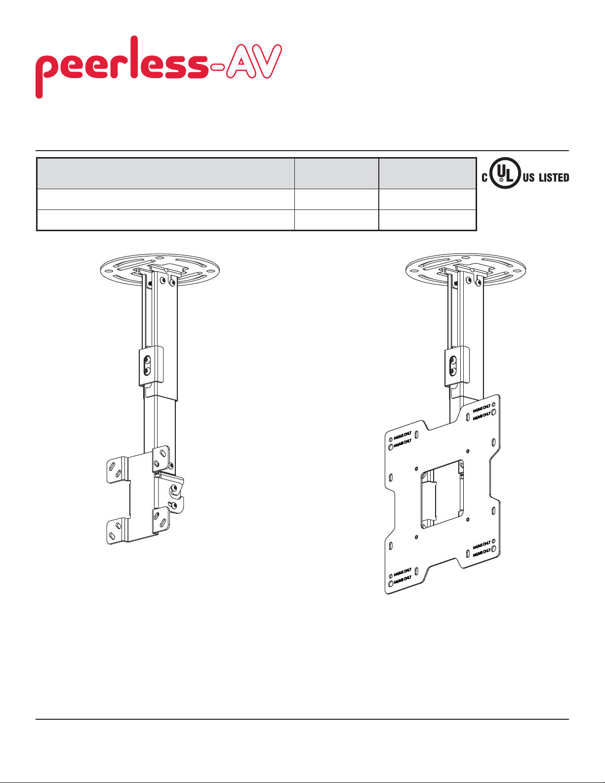
Installation and Assembly:
Ceiling Mount for 15" - 40" Flat Panel Displays
Models
PC930A, PC930A-S, PC930A-W, PC930B, PC930B-S, PC930B-W,
PC930C, PC930C-S, PC930C-W
PC932A, PC932A-S, PC932A-W, PC932B, PC932B-S, PC932B-W,
PC932C, PC932C-S, PC932C-W
PC930 Series PC932 Series
Screen Size Range Max UL Load Capacity
15" to 24" 50 lb (22.7 kg)
15" to 40" 80 lb (36.3 kg)
Features:
• VESA® 75 / 100 / 200x100 / 200x200 compatible
• Three adjustable extension lengths:
PC930A/PC932A models - 9.8" - 13.9"
PC930B/ PC932B models - 13.78" - 21.89"
PC930C/ PC932C models - 20.24" - 34.02"
• Adjustable tilt of +20/-5°
• 360° of mountable adjustment
• Internal cable management
• Safety catch designed into extension channels to ensure user and equipment safety
2300 White Oak Circle • Aurora, Il 60502 • (800) 865-2112 • Fax: (800) 359-6500 • www.peerlessmounts.com
ISSUED: 11-29-07 SHEET #: 202-9263-2 08-17-11
Note: Read entire instruction sheet before you start installation and assembly.
WARNING
• Do not begin to install your Peerless product until you have read and understood the instructions and warnings
contained in this Installation Sheet. If you have any questions regarding any of the instructions or warnings, for US
customers please call Peerless customer care at 1-800-865-2112, for all international customers, please contact
your local distributor.
• This product should only be installed by someone of good mechanical aptitude, has experience with basic building
construction, and fully understands these instructions.
• Make sure that the supporting surface will safely support the combined load of the equipment and all attached
hardware and components.
• Never exceed the Maximum UL Load Capacity. See page one.
• If mounting to wood ceiling studs, make sure that mounting screws are anchored into the center of the studs. Use
of an "edge to edge" stud fi nder is highly recommended.
• Always use an assistant or mechanical lifting equipment to safely lift and position equipment.
• Tighten screws fi rmly, but do not overtighten. Overtightening can damage the items, greatly reducing their holding
power.
• This product is intended for indoor use only. Use of this product outdoors could lead to product failure and personal
injury.
• This product was designed to be installed on the following ceiling construction only;
CEILING CONSTRUCTION HARDWARE REQUIRED
• Wood Stud, Joist Included
• Wood Beam Included
• Solid Concrete Included
• Cinder Block Contact Qualifi ed Professional
• Metal Stud Do not attach except with Peerless accessory kit for metal studs;
Contact Customer Service for Peerless accessory kit for metal studs.
(not evaluated by UL)
• Brick Contact Qualifi ed Professional (not evaluated by UL)
• Other or unsure? Contact Qualifi ed Professional
Tools Needed for Assembly
• stud fi nder ("edge to edge" stud fi nder is recommended)
• drill
• level
• 5/16" bit for concrete
• 5/32" bit for wood joist
• phillips screwdriver
Table of Contents
Parts List............................................................................................................................................................................ 3, 4
Install Outer Channel to Ceiling Plate.....................................................................................................................................4
Installation to Wood Joist ........................................................................................................................................................5
Installation to Concrete Ceilings .............................................................................................................................................6
Installing Inner Channel and Routing Cables .........................................................................................................................7
Attaching Mounting Plate to Display with VESA 75 or 100 Mounting Pattern ........................................................................8
Attaching Adapter Plate to Display with VESA 200 x 100 or 200 x 200 Mounting Pattern .....................................................9
Installing Flat Panel Display ............................................................................................................................................... 10
Adjusting Mount Extension .................................................................................................................................................. 10
Adjusting Display ..................................................................................................................................................................11
Install Cable Covers .............................................................................................................................................................11
2 of 35
ISSUED: 11-29-07 SHEET #: 202-9263-2 08-17-11

Before you begin, make sure all parts shown are included with your product.
,
C
,
S
,
W
,
C
,
S
,
W
PC930A
Parts List
Description Qty.
A
ceiling plate 1 055-1773 055-4773 055-2773 055-1773 055-4773 055-2773
B
outer channel 1 See Chart See Chart See Chart See Chart See Chart See Chart
C
inner channel 1 See Chart See Chart See Chart See Chart See Chart See Chart
D
clamp plate 1 055-1771 055-4771 055-2771 055-1771 055-4771 055-2771
E
swivel/pivot bracket 1 055-1811 055-4811 055-2811 055-1811 055-4811 055-2811
F
tilt bracket 1 095-1484 095-4484 095-2484 095-1484 095-4484 095-2484
G
cable cover 2 See Chart See Chart See Chart See Chart See Chart See Chart
H
#14 x 2.5 wood screw 2 5S1-015-C03 5S1-015-C04 5S1-015-C04 5S1-015-C03 5S1-015-C04 5S1-015-C04
I
concrete anchor 2 590-0320 590-0320 590-0320 590-0320 590-0320 590-0320
J
M5 x 10 mm socket pin screw 8 520-1063 520-2063 520-2063 520-1063 520-2063 520-2063
K
M6 x 10 mm socket pin screw 4 520-1066 520-2066 520-2066 520-1066 520-2066 520-2066
L
M6 x 12 mm socket pin screw 2 520-1050 520-2050 520-2050 520-1050 520-2050 520-2050
M
M4 x 10 mm socket pin screw 4 520-1060 520-2060 520-2060 520-1060 520-2060 520-2060
N M4 x 12 mm socket pin serrated
washer head screw
O
M4 x 20 mm socket pin screw 4 520-1061 520-2163 520-2163 520-1061 520-2163 520-2163
P
retaining spacer 4 590-5005 590-5005 590-5005 590-5005 590-5005 590-5005
Q
4 mm security allen wrench 1 560-9646 560-9646 560-9646 560-9646 560-9646 560-9646
R
adapter plate 1 N/A N/A N/A 095-1721 095-4721 095-2721
S
M5 x 6 mm socket pin screw 4 N/A N/A N/A 520-1114 520-2062 520-2062
T
#10 flat washer 4 N/A N/A N/A 540-9400 540-9442 540-9442
U
M6 x 12 mm socket pin screw 4 N/A N/A N/A 520-1050 520-2050 520-2050
V
M6 x 20 mm socket pin screw 4 N/A N/A N/A 520-9554 520-2554 520-2554
W
M8 x 10 mm socket pin screw 4 N/A N/A N/A 520-1706 520-2706 520-2706
PC930B,
PC930
Part # Part # Part # Part # Part # Part #
4 510-1079 510-2079 510-2079 510-1079 510-2079 510-2079
PC930A-S
PC930B-S,
PC930C-
PC930A-W
PC930B-W,
PC930C-
PC932A
PC932B,
PC932
PC932A-S
PC932B-S,
PC932C-
PC932A-W
PC932B-W,
PC932C-
Parts may appear slightly different than illustrated.
OUTER CHANNEL, INNER CHANNEL AND CABLE COVER
PART NUMBER CHART
extendable
Model# part # part # part #
length
PC930A, PC932A 9.8" - 13.9" 055-1779 055-1778 055-1809-2
PC930A-S, PC932A-S 9.8" - 13.9" 055-4779 055-4778 055-4809-2
PC930A-W, PC932A-W 9.8" - 13.9" 055-2779 055-2778 055-2809-2
PC930B, PC932B 13.78" - 21.89" 055-1776 055-1775 055-1809-1
PC930B-S, PC932B-S 13.78" - 21.89" 055-4776 055-4775 055-4809-1
PC930B-W, PC932B-W 13.78" - 21.89" 055-2776 055-2775 055-2809-1
PC930C, PC932C 20.24" - 34.02" 055-1770 055-1769 055-1809
PC930C-S, PC932C-S 20.24" - 34.02" 055-4770 055-4769 055-4809
PC930C-W, PC932C-W 20.24" - 34.02" 055-2770 055-2769 055-2809
outer channel (B) inner channel (C) cable cover (G)
3 of 35
ISSUED: 11-29-07 SHEET #: 202-9263-2 08-17-11

Part List Continued
Parts may appear slightly different than illustrated.
ABCDE
G
HI
F
JKL M NOP
Q
R
Install Outer Channel to Ceiling Plate
Attach outer channel (B) to ceiling plate (A) using
1
four M6 x 10 mm socket pin screws (K) as shown.
SUVT
W
K
A
4 of 35
B
ISSUED: 11-29-07 SHEET #: 202-9263-2 08-17-11

Installation to Wood Joist Ceilings
WARNING
• Installer must verify that the supporting surface will safely support the combined load of the equipment and all
attached hardware and components.
• Tighten wood screws so that ceiling plate is fi rmly attached, but do not overtighten. Overtightening can damage the
screws, greatly reducing their holding power.
• Never tighten in excess of 80 in. • lb (9 N.M.).
• Make sure that mounting screws are anchored into the center of the stud or joist. The use of an "edge to edge" stud
fi nder is highly recommended.
• Hardware provided is for attachment of mount through standard thickness drywall or plaster into wood studs or
joists. Installers are responsible to provide hardware for other types of mounting situations (not evaluated by UL).
Use a stud fi nder to locate the edges of the joist. Use of an edge-to-edge stud fi nder is highly recommended.
2
Based on its edges, draw a vertical line down the joist’s center. Place ceiling plate (A) on ceiling as a template,
making sure that the two mounting slots are on the stud centerline.
Note: Opening on outer channel (B) indicates front of mount. Use the correct mounting slots on the ceiling plate
depending on ceiling joist orientation as shown in fi gure 2.1 or fi gure 2.2. Mounting slots on ceiling plate allow for
45° (
±22.5) of swivel adjustment before securing to joist.
Mark the center of the two mounting holes depending on joist orientation as shown in fi gure 2.1 or fi gure 2.2. Drill
two 5/32" (4 mm) dia. holes 2-1/2" (65 mm) deep. Secure ceiling plate (A) to wood joist using two #14 x 2-1/2"
wood screws (H) as shown.
Skip to step 3.
fi g. 2.1
A
B
H
WOOD
JOIST
fi g. 2.2
MOUNTING SLOTS
ALLOW FOR ROTATION
BEFORE SECURING TO
JOIST
A
B
H
OPENING ON OUTER
CHANNEL (B) INDICATES
FRONT OF MOUNT
5 of 35
ISSUED: 11-29-07 SHEET #: 202-9263-2 08-17-11

Installation to Concrete Ceilings
WARNING
• Concrete must be 2000 psi density minimum. Lighter density concrete may not hold concrete anchor.
• Make sure that the supporting surface will safely support the combined load of the equipment and all attached hardware and components.
Place ceiling plate (A) on ceiling as a template and
2
mark the center of the two mounting holes.
Note: Opening in outer channel indicates the front
of the mount.
Drill two 5/16" (8 mm) dia. holes to a minimum
depth of 2.5" (64 mm). Attach ceiling plate (A) using
two concrete anchors (I) and two #14 x 2.5" wood
screws (H) as shown in fi gure 2.3. Tighten wood
screws (H) until ceiling plate (A) is fi rmly attached.
1
Drill holes and insert anchors (I).
2
A
concrete
surface
I
WARNING
• Tighten wood screws fi rmly, but do not overtighten.
Overtightening can damage the screws, greatly
reducing their holding power.
• Never tighten in excess of 80 in • lb (9 N.M.)
WARNING
• Always attach concrete expansion anchors directly
to load-bearing concrete.
• Never attach concrete expansion anchors to
concrete covered with plaster, drywall, or other
fi nishing material. If mounting to concrete surfaces
covered with a fi nishing surface is unavoidable (not
evaluated by UL), the fi nishing surface must be
counterbored as shown below. Be sure concrete
anchors do not pull away from concrete when
tightening screws. If plaster/drywall is thicker than
5/8" (16 mm), custom fasteners must be supplied by
installer (not evaluated by UL).
INCORRECT CORRECT
wall
plate
concrete
wall
plate
concrete
H
Place plate (A) over anchors (I) and secure with screws (H).
3
Tighten all fasteners.
CONCRETE CEILING
I
A
OPENING ON
OUTER CHANNEL
(B) INDICATES
FRONT OF MOUNT
B
fi g. 2.3
H
I
CUTAWAY VIEW
plaster/
dry wall
plaster/
dry wall
6 of 35
ISSUED: 11-29-07 SHEET #: 202-9263-2 08-17-11
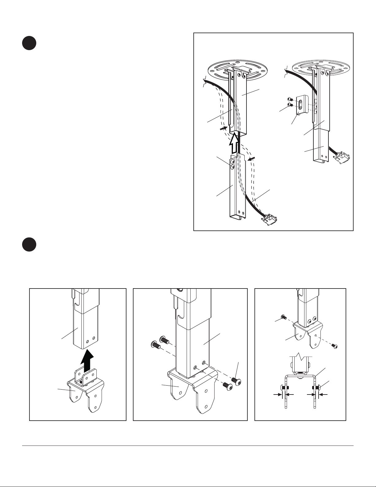
Installing Inner Channel and Routing Cables
Note: Be certain holes on inner channel (C) face in
3
the same direction of opening on outer channel (B).
Note: Cables must be removed from display
before routing through channels. If cables are not
removable from display, routing through channels is
not an option.
Guide display cables into openings in channels then
insert inner channel (C) into outer channel (B) as
shown in fi gure 3.1.
Position inner channel (C) to the desired height and
secure using two M6 x 12 mm socket pin
screws (L) through clamp plate (D), through opening
in outer channel (B) and into inner channel (C) as
shown in fi gure 3.2.
OPENING
fi g. 3.1
fi g. 3.2
B
L
D
B
HOLES
GUIDE
CABLES IN
C
Insert swivel/pivot bracket (E) into end of inner channel (C) and secure with four M5 x 10 mm socket pin screws (J)
4
as shown in fi gure 4.1 and fi gure 4.2.
Thread two M5 x 10 mm screws (J) into top holes of swivel/pivot bracket (E), leaving 1/8" (3 mm) exposed thread
between head of screw and swivel/pivot bracket as shown in fi gure 4.3.
CABLES NOT SHOWN FOR CLARITY
fi g. 4.1
fi g. 4.2
CHANNELS
fi g. 4.3
C
J
E
C
E
7 of 35
C
E
J
1/8"
(3 mm)
FRONT VIEW
ISSUED: 11-29-07 SHEET #: 202-9263-2 08-17-11
E
J
1/8"
(3 mm)

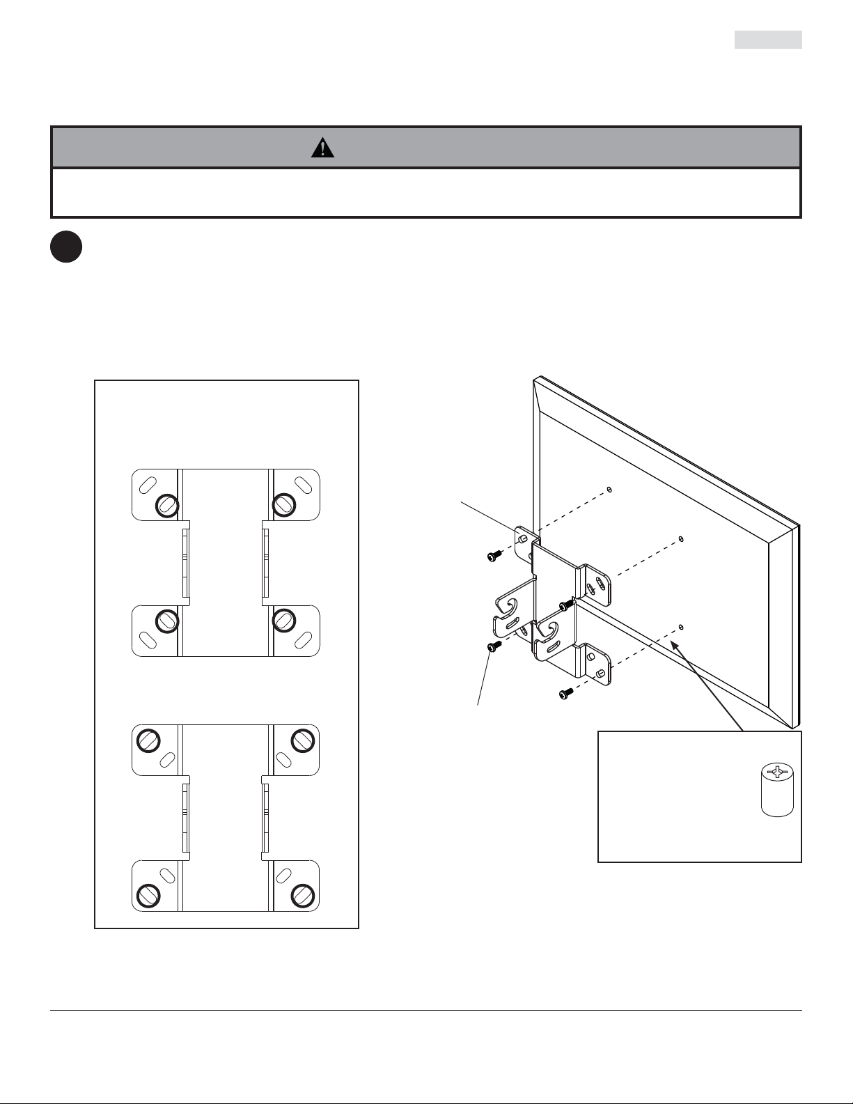
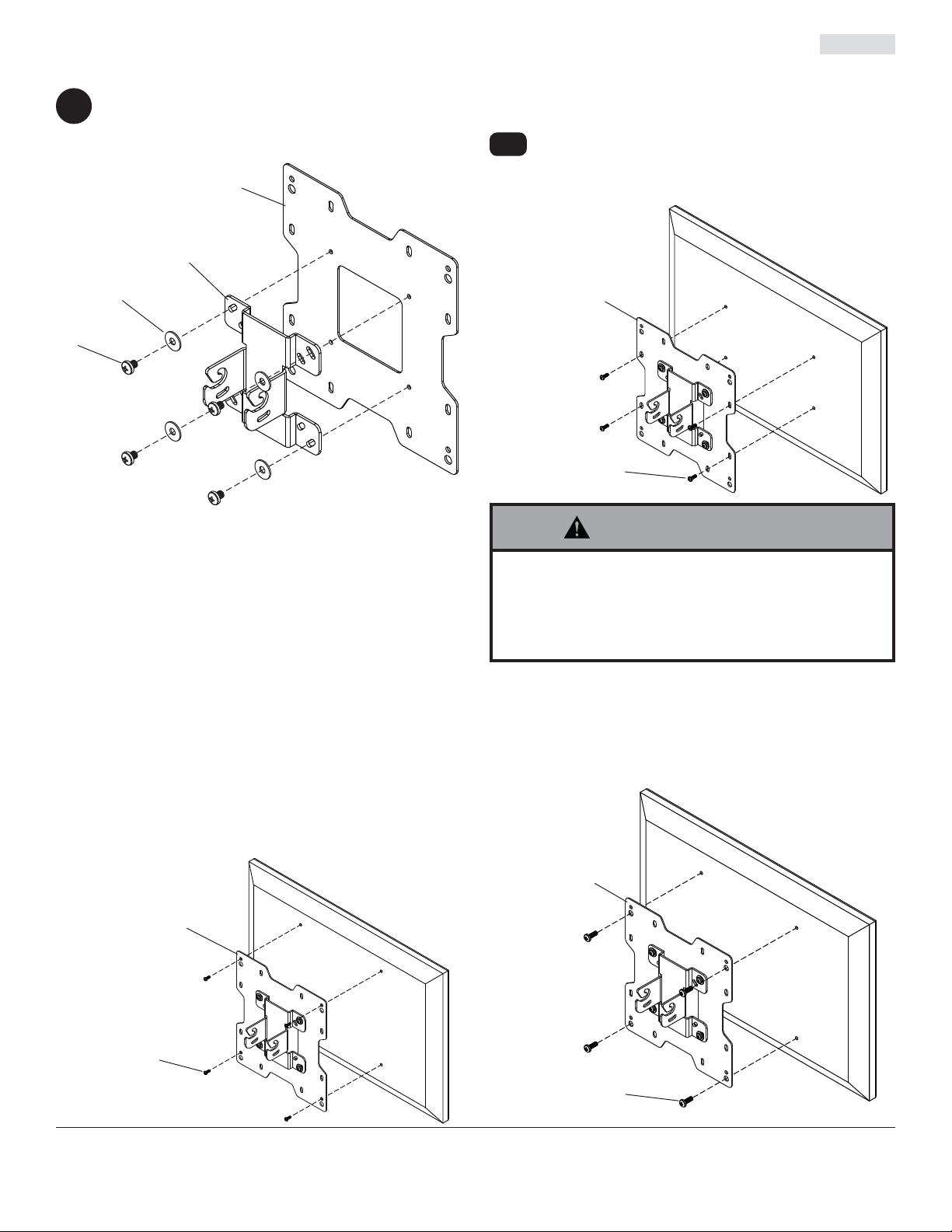
Attaching Mounting Plate to Display with VESA 75 or 100 Mounting Pattern
Note: For VESA 200 x 100 mm and 200 x 200 mm hole patterns, see following page.
WARNING
• If screws don't get three complete turns in the display inserts or if screws bottom out and bracket is still not tightly
secured, damage may occur to display or product may fail.
Choose hole pattern as shown in fi gure 5.1 which matches hole pattern on back of your display. Attach tilt bracket
5
(F) to back of display using four M4 x 10 mm screws (M) or M4 x 12 mm screws (N) as shown in fi gure 5.2.
*NOTE: If hole pattern is in a pocket, attach tilt bracket (F) to back of display using four M4 x 20 mm screws (O)
and four retaining spacers (P) as indicated in fi gure 5.2.
Skip to step 6.
fi g. 5.1
FOR VESA 75 MOUNTING PATTERN:
FOR VESA 100 MOUNTING PATTERN:
fi g. 5.2
F
M, N or O
*For displays with a hole
pattern in a pocket, spacers
go between tilt bracket and
display when used with
M4 x 20 mm screws (O).
P
8 of 35
ISSUED: 11-29-07 SHEET #: 202-9263-2 08-17-11

Attaching Adapter Plate to Display with VESA 200 or 200 x 100 Mounting Pattern
Attach tilt bracket (F) onto adapter plate (R) using
5
four M5 x 6 mm screws (S) and #10 washers (T) as
shown.
R
F
T
S
FOR VESA 200 x 100 MOUNTING PATTERN:
Choose hole pattern as shown below. Attach
5-1
adapter plate (R) to back of display using four
M4 screws (M, N, O) as shown below.
R
M, N, O
FOR VESA 200 MOUNTING PATTERN USING
M4 SCREWS:
Choose hole pattern as shown below. Attach adapter plate
(R) to back of display using four M4 screws (M or N) as
shown below.
NOTE: If screw (M or N) gets less than three threads of
engagement, attach adapter plate (R) to back of display
using four M4 x 20 mm screws (O) and four spacers (P) as
indicated below.
R
WARNING
• If screws don't get three complete turns in the
display inserts or if screws bottom out and bracket is
still not tightly secured, damage may occur to display
or product may fail.
FOR VESA 200 MOUNTING PATTERN USING
M6 OR M8 SCREWS:
Choose hole pattern as shown below. Attach adapter plate
(R) to back of display using four M6 or M8 screws (U, V,
W) as shown below.
R
M, N, O
9 of 35
U, V, W
ISSUED: 11-29-07 SHEET #: 202-9263-2 08-17-11
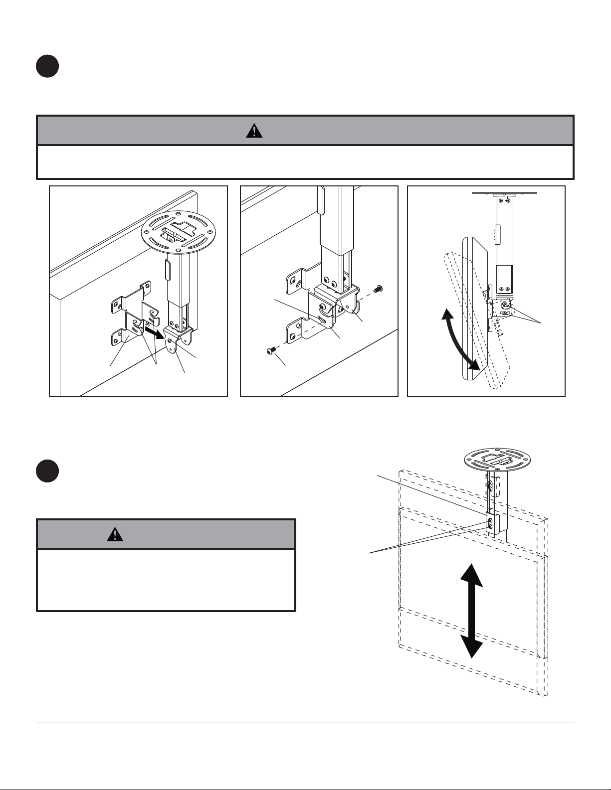
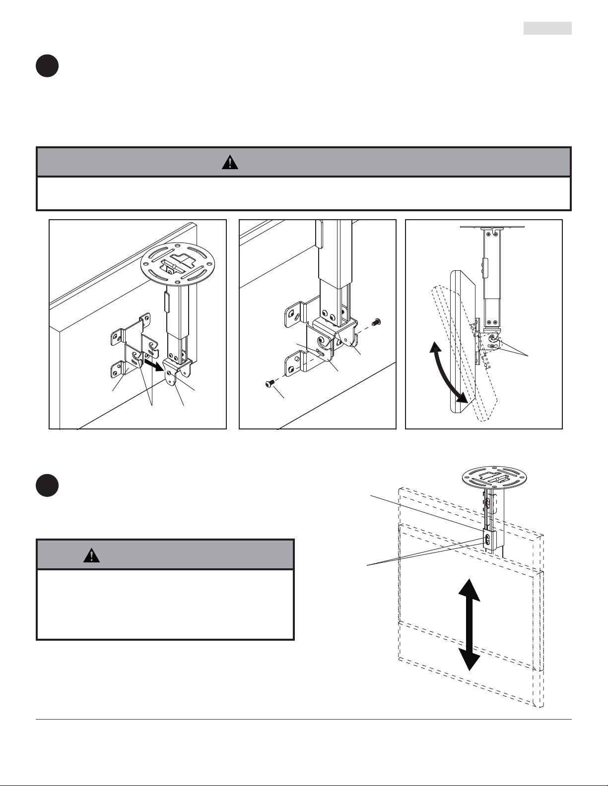
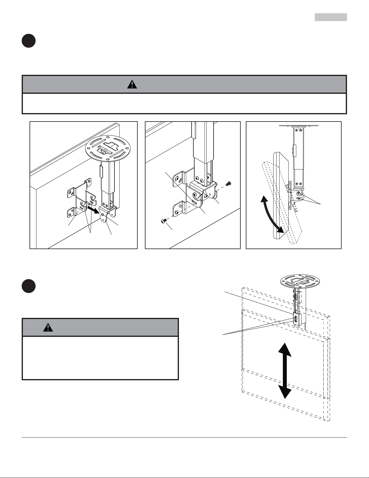
Attaching Display
Guide hook slots of tilt bracket (F) onto M5 x 10 mm screws (J) in swivel/pivot bracket (E) as shown in fi gure 6.1.
6
Thread two M5 x 10 mm screws (J) through tilt slot of tilt bracket (F) into swivel/pivot bracket (E) as shown in
fi gure 6.2. Do not fully tighten screws to allow for tilt adjustments. Tilt slot allows for incremental tilts of 5°.
Adjust tilt of display and fully tighten all four M5 x 10 mm screws (J) as shown in fi gure 6.3.
WARNING
• Do not lift more weight than you can handle. Use additional man power or mechanical lifting equipment to safely
handle placement of the display.
fi g. 6.1
fi g. 6.3
TILT
SLOTS
F
HOOK
SLOTS
J
E
Adjusting Mount Extension
While supporting the weight of the display, loosen
7
screws (L) on clamp plate (D) half a turn and
position display to the desired height.
Retighten clamp plate screws securely.
WARNING
• Clamp plate adjustment screws support weight of
display when fully tightened. Weight of the display
will need to be supported if clamp plate screws are
loosened.
J
E
F
fi g. 6.2
D
L
CLAMP PLATE
SCREWS
J
10 of 35
ISSUED: 11-29-07 SHEET #: 202-9263-2 08-17-11

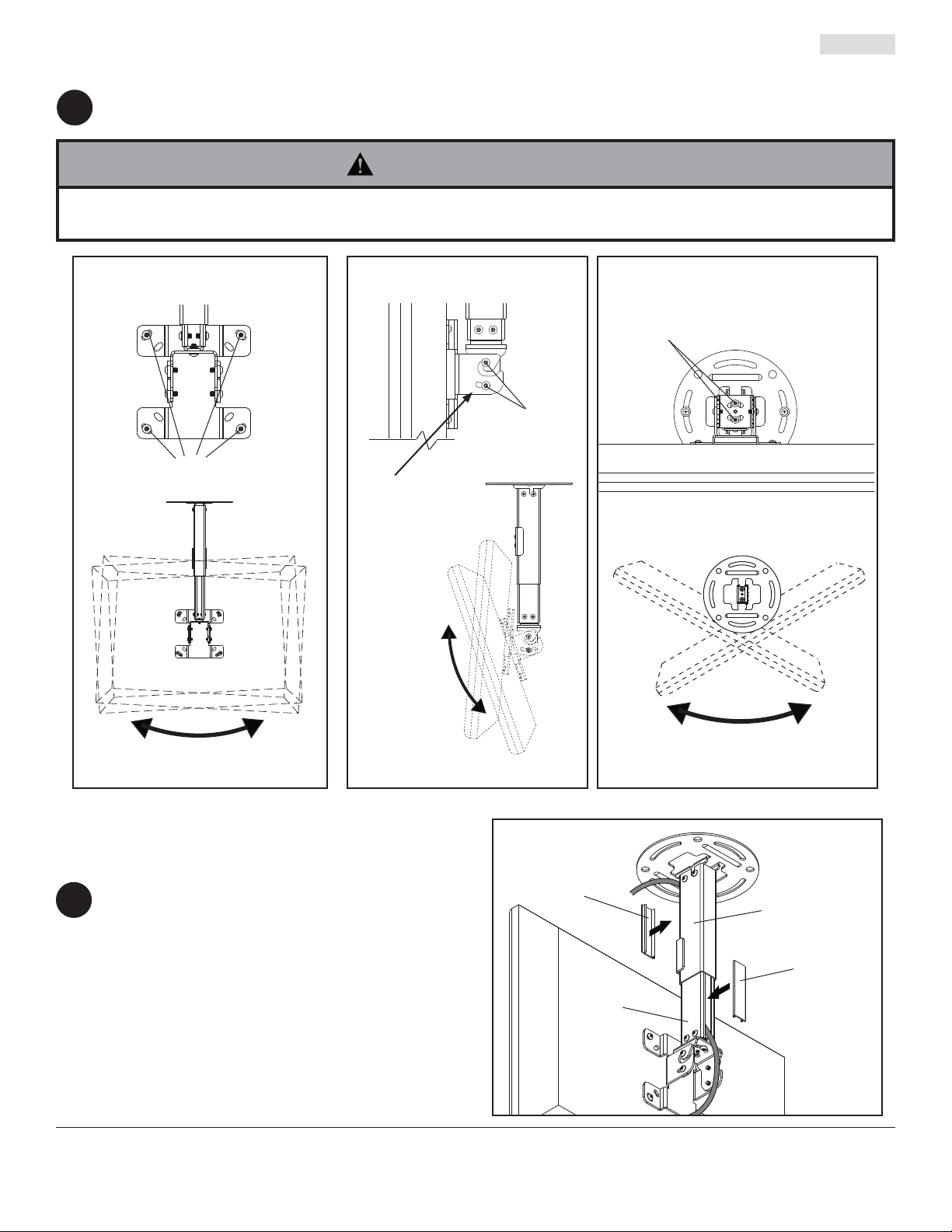
Adjusting Display
If screws indicated are fully tightened, loosen screws half a turn to allow for adjusting tilt, swivel and roll. Adjust
8
display to the desired position and fully tighten screws.
WARNING
• Do not loosen adjustment screws to the point they become disengaged from the mount. Weight of the display
should be supported in case of accidental disengagement.
ROLL ADJUSTMENT
BACK VIEW
SCREWS FOR
ROLL ADJUSTMENT
TILT ADJUSTMENT
SIDE VIEW
SCREWS FOR
TILT ADJUSTMENT
(BOTH SIDES)
SLOT ALLOWS FOR
INCREMENTAL TILT
ADJUSTMENTS OF 5°
SWIVEL ADJUSTMENT
BOTTOM VIEW
SCREWS FOR SWIVEL ADJUSTMENT
Install Cable Covers
NOTE: Be certain mount is in the desired
9
extended position.
Attach cables to display if routed through
channels.
Cut cable covers (G) to the length of inner
channel (C) and outer channel (B) openings,
leaving space for cables if routed through
channels. Snap cable covers into openings as
shown.
Cables not routed through channels will
require cable ties (not included).
25° (+20°/-5°) TILT
11 of 35
All other brand and product names are trademarks or registered trademarks of their respective owners.
G
CUT TO
LENGTH OF
OPENING
90° (±45°) SWIVEL6° (±3°) ROLL
B
G
CUT TO
C
ISSUED: 11-29-07 SHEET #: 202-9263-2 08-17-11
© 2011, Peerless Industries, Inc. All rights reserved.
LENGTH OF
OPENING

Instalación y ensamblaje:
Soporte de Techo para 15" - 40" Pantallas
Modelos
PC930A, PC930A-S, PC930A-W, PC930B, PC930B-S, PC930B-W,
PC930C, PC930C-S, PC930C-W
PC932A, PC932A-S, PC932A-W, PC932B, PC932B-S, PC932B-W,
PC932C, PC932C-S, PC932C-W
PC930 Serie PC932 Serie
Gama de tamaño de
las pantallas
de 15" a 24" 50 lb (22.7 kg)
de 15" a 40" 80 lb (36.3 kg)
Capacidad de carga
máxima de UL
Características:
• Compatible con VESA® 75 / 100 / 200 x 100 / 200 x 200
• Tres longitudes de extensión ajustable
PC930A/PC932A modelos - 9.8" - 13.9"
PC930B/ PC932B modelos - 13.78" - 21.89"
PC930C/ PC932C modelos - 20.24" - 34.02"
• Inclinación ajustable de +20/-5°
•
360° de ajuste al instalar
• Manejo de cables interno
• Dispositivo asegurador de diseño integrado a los rieles de extensión para garantizar la seguridad del usuario y del equipo
2300 White Oak Circle • Aurora, Il 60502 • (800) 865-2112 • Fax: (800) 359-6500 • www.peerlessmounts.com
PUBLICADO: 11-29-07 HOJA #: 202-9263-2 08-17-11

Español
Nota:
Lea la hoja de instrucciones completa antes de comenzar la instalación y el ensamblaje.
ADVERTENCIA
• No comience a instalar el producto hasta haber leído y entendido las instrucciones y las advertencias contenidas
en la Hoja de Instalación. Si tiene alguna pregunta acerca de cualquiera de las instrucciones o las advertencias, por
favor, llame a Servicio al Cliente al 1-800-865-2112.
• Este producto sólo debe ser instalado por una persona que tenga una buena aptitud mecánica, que tenga experiencia
en construcción básica de edifi cios y que entienda estas instrucciones en su totalidad.
• Asegúrese de que la superfi cie de apoyo sostendrá, con seguridad, la carga combinada del equipo y todos los
fi jadores y componentes.
• Nunca sobrepase la capacidad máxima de soportar carga aceptada por Underwriters Laboratories. Vea la página 12.
• Si va a instalar el producto en un techo con vigas de madera, asegúrese de que los tornillos de montaje estén
anclados en el centro de las vigas. Se recomienda utilizar un localizador de montantes de “borde a borde”.
• Siempre cuente con la ayuda de un asistente o utilice un equipo mecánico de izar para levantar y colocar el equipo
con más seguridad.
• Apriete los tornillos con fi rmeza, pero no en exceso. Apretarlos en exceso puede dañar los artículos y puede disminuir
signifi cativamente su fuerza de fi jación.
• Este producto está diseñado para uso en interiores solamente. Utilizar este producto en exteriores podría causar
fallas del producto y lesiones a individuos.
• Este producto fue diseñado para ser instalado en paredes con la siguiente construcción solamente:
CONSTRUCCIÓN DE LA PARED ACCESORIOS NECESARIOS
• Montante de madera Incluido
• Viga de madera Incluido
• Concreto macizo Incluido
• Bloque de hormigón de escorias Comuníquese con un profesional califi cado
• Montante de metal No lo instale excepto con el juego de accesorios de Peerless para
montantes de metal (no evaluados por UL)
• Ladrillo Comuníquese con un profesional califi cado (no evaluados por UL)
• ¿Otra superfi cie o no está seguro? Comuníquese con un profesional califi cado
Herramientas necesarias para el
ensamblaje
• localizador de montantes (se recomienda uno de “borde
a borde”)
• taladro
• nivel
• broca de 5/16" para concreto
• broca de 5/32" para vigas de madera
• destornillador phillips
Tabla de contenido
Lista de piezas............................................................................................................................................................... 14, 15
Instalación del riel exterior en la placa de techo.................................................................................................................. 15
Instalación en vigas de madera ........................................................................................................................................... 16
Instalación en techos de concreto ....................................................................................................................................... 17
Instalación del riel interior y colocación de los cables ......................................................................................................... 18
Fijación de la placa de montaje a pantallas con confi guraciones de montaje VESA
Fijación de la placa adaptadora a pantallas con confi guraciones de montaje VESA
Instalación de la pantalla plana .......................................................................................................................................... 21
Ajuste de la extensión del soporte....................................................................................................................................... 21
Ajuste de la pantalla ............................................................................................................................................................ 22
Instalación de las cubiertas de los cables ........................................................................................................................... 22
13 de 35
®
75 ó 100 ......................................... 19
®
200 x 100 ó 200 x 200 ................... 20
PUBLICADO: 11-29-07 HOJA #: 202-9263-2 08-17-11

Español
,
C
,
S
,
W
,
C
,
S
,
W
a
a
p
Antes de comenzar, asegúrese de que su producto contiene todas las piezas que se muestran.
PC930A
Lista de piezas
Descripción Cant.
A
placa de techo 1 055-1773 055-4773 055-2773 055-1773 055-4773 055-2773
B
riel exterior 1 Vea la tabla Vea la tabla Vea la tabla Vea la tabla Vea la tabla Vea la tabla
C
riel interior 1 Vea la tabla Vea la tabla Vea la tabla Vea la tabla Vea la tabla Vea la tabla
D
placa abrazadera 1 055-1771 055-4771 055-2771 055-1771 055-4771 055-2771
E
soporte giratorio / rotatorio 1 055-1811 055-4811 055-2811 055-1811 055-4811 055-2811
F
soporte inclinable 1 095-1484 095-4484 095-2484 095-1484 095-4484 095-2484
G
cubierta para los cables 2 Vea la tabla Vea la tabla Vea la tabla Vea la tabla Vea la tabla Vea la tabla
H
tornillo para madera de 14 x 2.5" 2 5S1-015-C03 5S1-015-C04 5S1-015-C04 5S1-015-C03 5S1-015-C04 5S1-015-C04
I
Anclaje para concreto 2 590-0320 590-0320 590-0320 590-0320 590-0320 590-0320
J
tornillo pasador de cabeza hueca de M5 x 10 mm 8 520-1063 520-2063 520-2063 520-1063 520-2063 520-2063
K
tornillo pasador de cabeza hueca de M6 x 10 mm 4 520-1066 520-2066 520-2066 520-1066 520-2066 520-2066
L
tornillo pasador de cabeza hueca de M6 x 12 mm 2 520-1050 520-2050 520-2050 520-1050 520-2050 520-2050
M
tornillo pasador de cabeza hueca de M4 x 10 mm 4 520-1060 520-2060 520-2060 520-1060 520-2060 520-2060
N tornillo pasador de cabeza hueca con arandela
dentada de M4 x 12 mm
O
tornillo pasador de cabeza hueca de M4 x 20 mm 4 520-1061 520-2163 520-2163 520-1061 520-2163 520-2163
P
espaciador de retención 4 590-5005 590-5005 590-5005 590-5005 590-5005 590-5005
Q
llave allen de seguridad de 4 mm 1 560-9646 560-9646 560-9646 560-9646 560-9646 560-9646
R
placa adaptadora 1 N/A N/A N/A 095-1721 095-4721 095-2721
S
tornillo pasador de cabeza hueca de M5 x 6 mm 4 N/A N/A N/A 520-1114 520-2062 520-2062
T
arandela
U
tornillo pasador de cabeza hueca de M6 x 12 mm 4 N/A N/A N/A 520-1050 520-2050 520-2050
V
tornillo pasador de cabeza hueca de M6 x 20 mm 4 N/A N/A N/A 520-9554 520-2554 520-2554
W tornillo pasador de cabeza hueca de M8 x 10 mm 4 N/A N/A N/A 520-1706 520-2706 520-2706
lana No 10
PC930B,
PC930
N.o de piez
4 510-1079 510-2079 510-2079 510-1079 510-2079 510-2079
4 N/A N/A N/A 540-9400 540-9442 540-9442
PC930A-S
PC930B-S,
PC930CN.o de piezaN.o de piezaN.o de piezaN.o de piezaN.o de piez
PC930A-W
PC930B-W,
PC930C-
PC932A
PC932B,
PC932
PC932A-S
PC932B-S,
PC932C-
PC932A-W
PC932B-W,
PC932C-
Las piezas pueden verse un poco distintas a la ilustración.
TABLA DE NÚMEROS DE PIEZA DEL RIEL EXTERIOR, EL
RIEL INTERIOR Y LA CUBIERTA PARA LOS CABLES
Longitud
N.o de modelo N.o de pieza N.o de pieza N.o de pieza
alargable
PC930A, PC932A 9.8" - 13.9" 055-1779 055-1778 055-1809-2
PC930A-S, PC932A-S 9.8" - 13.9" 055-4779 055-4778 055-4809-2
PC930A-W, PC932A-W 9.8" - 13.9" 055-2779 055-2778 055-2809-2
PC930B, PC932B 13.78" - 21.89" 055-1776 055-1775 055-1809-1
PC930B-S, PC932B-S 13.78" - 21.89" 055-4776 055-4775 055-4809-1
PC930B-W, PC932B-W 13.78" - 21.89" 055-2776 055-2775 055-2809-1
PC930C, PC932C 20.24" - 34.02" 055-1770 055-1769 055-1809
PC930C-S, PC932C-S 20.24" - 34.02" 055-4770 055-4769 055-4809
PC930C-W, PC932C-W 20.24" - 34.02" 055-2770 055-2769 055-2809
riel exterior (B) riel interior (C) cubierta para los cables (G)
14 de 35
PUBLICADO: 11-29-07 HOJA #: 202-9263-2 08-17-11

Lista de piezas - continuación
Las piezas pueden verse un poco distintas a la ilustración.
ABCDE
G
HI
F
Español
JKL M NOP
Q
R
Instalación del Riel Exterior a la Placa de Techo
Fije el riel exterior (B) a la placa de techo (A)
1
usando cuatro tornillos pasadores de cabeza hueca
de M6 x 10 mm (K), como se muestra.
SUVT
W
K
A
15 de 35
B
PUBLICADO: 11-29-07 HOJA #: 202-9263-2 08-17-11

Instalación en Paredes con Vigas de Madera
Español
ADVERTENCIA
• El instalador tiene que asegurarse de que la superfi cie de apoyo sostendrá, con seguridad, la carga combinada del
equipo y todos los fi jadores y componentes.
• Apriete los tornillos de madera de manera que la placa de techo se fi je fi rmemente, pero no en exceso. Apretarlos
en exceso puede dañar los tornillos y puede disminuir signifi cativamente su fuerza de fi jación.
• Nunca apriete a más de 80 pulg-lb (9 N•m).
• Asegúrese de que los tornillos de montaje estén anclados en el centro del montante o de la viga. Se recomienda
utilizar un localizador de montantes de “borde a borde”.
• Los accesorios para la instalación que se proveen son para fi jar el soporte a montantes de madera o vigas de
madera a través del yeso-cartón o yeso de grosor estándar. Los instaladores son responsables de suministrar los
accesorios necesarios para otros tipos de instalaciones
Utilice un localizador de montantes para localizar los bordes de las vigas. Se recomienda utilizar un localizador
2
de montantes de “borde a borde”. Tomando los bordes como punto de referencia, trace una línea vertical por el
centro de la viga. Coloque la placa de techo (A) en el techo para utilizarla como plantilla; asegúrese de que las dos
ranuras de montaje estén sobre la línea que trazó por el centro.
Nota: La abertura del riel exterior (B) indica la parte delantera del soporte. Utilice las ranuras de montaje
apropiadas de la placa de techo, según la orientación de la viga, como se muestra en la fi gura 2.1 o en la fi gura
2.2. Las ranuras de montaje de la placa de techo permiten una rotación de 45° (±22.5) antes de fi jar el soporte a la
viga.
Marque el centro de los dos agujeros de montaje según la orientación de la viga, como se muestra en la fi gura 2.1
o en la fi gura 2.2. Taladre dos agujeros de 5/32" (4 mm) de diámetro y 2-1/2" (65 mm) de profundidad. Fije la placa
de techo (A) a la viga de madera usando dos tornillos para madera de 14 x 2-1/2" (H), como se muestra.
Pase al paso 3.
(no evaluados por UL).
fi g. 2.1
A
B
H
VIGA DE
MADERA
LAS RANURAS DE
MONTAJE PERMITEN LA
ROTACIÓN ANTES DE
FIJAR EL SOPORTE A LA
VIGA
LA ABERTURA DEL RIEL
EXTERIOR (B) INDICA LA
PARTE DELANTERA DEL
SOPORTE
16 de 35
fi g. 2.2
A
B
H
PUBLICADO: 11-29-07 HOJA #: 202-9263-2 08-17-11

Instalación en Techos de Concreto
Español
ADVERTENCIA
• El concreto tiene que tener una densidad mínima de 2,000 psi. Es posible que un concreto de menos densidad no
sostenga el anclaje para concreto.
• Asegúrese de que la superfi cie de apoyo sostendrá, con seguridad, la carga combinada del equipo y todos los
fi jadores y componentes.
Coloque la placa de techo (A) contra el techo a
2
manera de plantilla y marque el centro de los dos
agujeros de montaje.
Nota: La abertura del riel exterior indica la parte
delantera del soporte.
Taladre dos agujeros de 5/16" (8 mm) de diámetro
a una profundidad mínima de 2.5" (64 mm). Fije
la placa de techo (A) utilizando dos anclajes para
concreto (I) y dos tornillos para madera de
14 x 2.5" (H), como se muestra en fi gura 2.3.
Apriete los tornillos para madera (H) hasta que la
placa de techo (A) se fi je fi rmemente.
1
Taladre los agujeros e inserte los anclajes (I).
2
A
H
Coloque la placa (A) sobre los anclajes (H) y fíjela con los tornillos (I).
techo de
concreto
I
I
ADVERTENCIA
• Apriete los tornillos para madera con fi rmeza, pero
no en exceso. Apretarlos en exceso puede dañar
los tornillos y puede disminuir signifi cativamente su
fuerza de fi jación.
• Nunca apriete a más de 80 pulg-lb (9 N•m).
ADVERTENCIA
• Siempre fi je los anclajes para concreto directamente
en la pared que sostiene la carga.
• Nunca fi je los anclajes para concreto a una pared de
concreto recubierta con yeso, tabique de yeso-cartón
u otro material de acabado. Si es inevitable hacer la
instalación en una superfi cie de concreto recubierta
con una superfi cie de acabado (no evaluados por
UL), la superfi cie de acabado tiene que ser escariada,
como se muestra abajo. Asegúrese de que los
anclajes para concreto no se separen del concreto
cuando apriete los tornillos. Si el grosor de la capa
de yeso o tabique de yeso-cartón tiene un grosor
mayor de 5/8", el instalador tiene que suministrar las
fi jaciones especiales (no evaluados por UL)
.
3
Apriete todas las fi jaciones.
TECHO DE CONCRETO
I
A
LA ABERTURA DEL
RIEL EXTERIOR (B)
INDICA LA PARTE
DELANTERA DEL
SOPORTE
H
fi g. 2.3
B
placa
de
pared
VISTA EN CORTE
INCORRECTO CORRECTO
concreto
yeso / tabique de yeso-cartón
placa
pared
de
concreto
17 de 35
PUBLICADO: 11-29-07 HOJA #: 202-9263-2 08-17-11

Instalación del Riel Interior y Colocación de los Cables
Nota:
Asegúrese de que los agujeros del riel
3
interior (C) se orienten en la misma dirección que la
abertura del riel exterior (B).
Nota: Tiene que quitar los cables de la pantalla
antes de acomodarlos en los rieles. Si los cables no
se pueden quitar de la pantalla, no tiene la opción
de acomodarlos en los rieles.
Acomode los cables de la pantalla en las aberturas
de los rieles, luego inserte el riel interior (C) en el
riel exterior (B), como se muestra en la fi gura 3.1.
Coloque el riel interior (C) a la altura deseada y
fíjelo pasando dos tornillos pasadores de cabeza
hueca de M6 x 12 mm (L) a través de la placa
abrazadera (D), la abertura del riel exterior (B) y el
riel interior (C), como se muestra en la fi gura 3.2.
ABERTURA
AGUJEROS
fi g. 3.1
C
Español
fi g. 3.2
B
L
D
B
C
ACOMODE
LOS CABLES
EN LOS
RIELES
Inserte el soporte giratorio / rotatorio (E) en el extremo del riel interior (C) y fíjelo con cuatro tornillos pasadores de
4
cabeza hueca de M5 x 10 mm (J), como se muestra en la fi gura 4.1 y en la fi gura 4.2.
Enrosque dos tornillos de M5 x 10 mm (J) en los agujeros superiores del soporte giratorio / rotatorio (E) y deje 1/8"
(3 mm) de la rosca expuesto entre la cabeza del tornillo y el soporte giratorio / rotatorio, como se muestra en la
fi gura 4.3.
LOS CABLES NO SE MUESTRAN POR RAZONES DE CLARIDAD
fi g. 4.1
fi g. 4.2
fi g. 4.3
J
C
C
E
J
E
E
1/8"
(3 mm)
VISTA DELANTERA
E
J
1/8"
(3 mm)
18 de 35
PUBLICADO: 11-29-07 HOJA #: 202-9263-2 08-17-11
Español
Fijación de la Placa de Montaje a Pantallas con Confi guraciones de Montaje
VESA
Nota: En el caso de las confi guraciones de montaje VESA® 200 x 100 y 200 x 200, pase a la próxima página.
®
75 ó 100
ADVERTENCIA
• Si no se les da tres vueltas completas a los tornillos en los insertos de la pantalla o si los tornillos topan fondo y el
soporte todavía no está fi rme, se podría dañar la pantalla o el producto podría no funcionar bien.
Seleccione la confi guración de agujeros, como se muestra en la fi gura 5.1, que sea igual a los agujeros de la parte
5
trasera de la pantalla. Fije el soporte inclinable (F) a la parte trasera de la pantalla usando cuatro tornillos de
M4 x 10 mm (M) o M4 x 12 mm (N), como se muestra en la fi gura 5.2.
*NOTA: Si la confi guración de agujeros está en una cavidad, fi je el soporte inclinable (F) a la parte trasera de la
pantalla usando cuatro tornillos de M4 x 20 mm (O) y cuatro espaciadores de retención (P), como se indica en la
fi gura 5.2.
Pase al paso 6.
fi g. 5.2
fi g. 5.1
EN EL CASO DE LA CONFIGURACIÓN
DE MONTAJE VESA® 75:
EN EL CASO DE LA CONFIGURACIÓN
DE MONTAJE VESA® 100:
F
M, N o O
*En el caso de las
pantallas que tienen la
confi guración de agujeros
en una cavidad, los
espaciadores van entre
el soporte inclinable y la
pantalla cuando use los
tornillos M4 x 20 mm (O).
P
19 de 35
PUBLICADO: 11-29-07 HOJA #: 202-9263-2 08-17-11
Fijación de la Placa Adaptadora a Pantallas con Confi guraciones de
Montaje VESA 200 ó 200 x 100
Fije el soporte inclinable (F) a la placa adaptadora
5
(R) usando cuatro tornillos de M5 x 6 mm (S) y
cuatro arandelas N.
o
10 (T), como se muestra.
R
PARA LAS CONFIGURACION DE MONTAJE
VESA 200 X 100 MM:
Escoja una confi guración de agujeros, como se
5-1
muestra abajo. Fije la placa adaptadora (R) a la
parte trasera de la pantalla usando cuatro tornillos
de M4 (M, N, O), como se muestra abajo.
F
Español
T
S
PARA LAS CONFIGURACION DE MONTAJE
VESA 200 MM USANDO M4 SCREWS:
Escoja una confi guración de agujeros, como se muestra
abajo. Fije la placa adaptadora (R) a la parte trasera de la
pantalla usando cuatro tornillos de M4 (M o N), como se
muestra abajo.
NOTA: Si el tornillo (M o N) enrosca menos de tres
vueltas, fi je la placa adaptadora (R) a la parte trasera de
la pantalla usando cuatro tornillos de M4 x 20 mm (O) y
cuatro espaciadores (P), como se indica abajo.
R
M, N, O
ADVERTENCIA
• Si no se les da tres vueltas completas a los tornillos
en los insertos de la pantalla o si los tornillos topan
fondo y el soporte todavía no está fi rme, se podría
dañar la pantalla o el producto podría no funcionar
bien.
PARA LAS CONFIGURACION DE MONTAJE
VESA 200 MM USANDO M6 O M8 SCREWS:
Escoja una confi guración de agujeros, como se muestra
abajo. Fije la placa adaptadora (R) a la parte trasera de
la pantalla usando cuatro tornillos de M6 o M8 (U, V, W),
como se muestra abajo.
M, N, O
R
20 de 35
R
U, V, W
PUBLICADO: 11-29-07 HOJA #: 202-9263-2 08-17-11
Español
Instalación de la Pantalla Plana
Deslice las ranuras de enganche del soporte inclinable (F) sobre los tornillos de M5 x 10 mm (J) del soporte
6
giratorio / rotatorio (E), como se muestra en la fi gura 6.1.
Enrosque dos tornillos de M5 x 10 mm (J) a través la ranura de inclinación del soporte inclinable (F), como se
muestra en la fi gura 6.2. No apriete los tornillos al máximo para que pueda ajustar la inclinación. La ranura de
inclinación permite ajustes en incrementos de 5°.
Ajuste la inclinación de la pantalla y apriete los cuatro tornillos de M5 x 10 mm (J) al máximo, como se muestra en
la fi gura 6.3.
ADVERTENCIA
• No levante más peso del que puede manejar. Cuente con otra persona que lo ayude o utilice un equipo mecánico
de izar para levantar y colocar la pantalla con seguridad.
fi g. 6.1
fi g. 6.3
RANURAS DE
INCLINACIÓN
F
RANURAS DE
ENGANCHE
J
E
Ajuste de la extensión del soporte
A la vez que sostiene el peso de la pantalla, afl oje
7
los tornillos (L) de la placa abrazadera (D) media
vuelta y coloque la pantalla a la altura deseada.
Apriete los tornillos de la placa abrazadera
fi rmemente.
ADVERTENCIA
• Los tornillos de ajuste de la placa abrazadera
sostienen el peso de la pantalla cuando están
apretados al máximo. Tendrá que sostener el peso
de la pantalla si afl oja los tornillos de la placa
abrazadera.
J
E
F
fi g. 6.2
D
L
TORNILLOS
DE LA PLACA
ABRAZADERA
J
21 de 35
PUBLICADO: 11-29-07 HOJA #: 202-9263-2 08-17-11
Ajuste de la Pantalla
Si los tornillos indicados están apretados al máximo, afl oje los tornillos media vuelta para poder ajustar la
8
inclinación, el giro y la rotación. Coloque la pantalla en la posición deseada y apriete los tornillos al máximo.
ADVERTENCIA
• No afl oje los tornillos de ajuste hasta el punto en que se salgan del soporte. Sostenga el peso de la pantalla en
caso de que se salga accidentalmente del soporte.
Español
AJUSTE DE LA ROTACIÓN
VISTA POSTERIOR
TORNILLOS PARA EL
AJUSTE DE LA ROTACIÓN
AJUSTE DE LA INCLINACIÓN
VISTA LATERAL
TORNILLOS PARA
EL AJUSTE DE LA
ROTACIÓN (AMBOS
LADOS)
LA RANURA PERMITE
EL AJUSTE DE LA
INCLINACIÓN EN
INCREMENTOS DE 5°
AJUSTE DEL GIRO
VISTA INFERIOR
TORNILLOS PARA EL AJUSTE DEL GIRO
INCLINACIÓN DE 25° (+20°/-5°) GIRO DE 90° (±45°)ROTACIÓN DE 6° (±3°)
Instalación de las cubiertas para los
cables
NOTA: Asegúrese de que el soporte esté en la
9
posición deseada de la extensión.
Conecte los cables a la pantalla si los acomodó en
los rieles.
Corte las cubiertas para los cables (G) de manera
que tengan la misma longitud de la abertura del
riel interior (C) y del riel exterior (B) y deje espacio
para pasar los cables si los acomodó en los rieles.
Coloque las cubiertas para los cables, a presión, en
las aberturas, como se muestra.
Necesitará sujetacables (no incluidos) para amarrar
los cables que no se acomoden en los rieles.
Cualesquiera otras marcas y nombres de productos son marcas comerciales o registradas de sus respectivos dueños.
22 de 35
G
CÓRTELAS DE LA
MISMA LONGITUD
DE LA ABERTURA
C
PUBLICADO: 11-29-07 HOJA #: 202-9263-2 08-17-11
B
G
CÓRTELAS
DE LA MISMA
LONGITUD DE
LA ABERTURA
© 2011, Peerless Industries, Inc. Todos los derechos reservados.
Installation et montage :
Support de Plafond pour 15 á 40" Écrans
Modèles
PC930A, PC930A-S, PC930A-W, PC930B, PC930B-S, PC930B-W,
PC930C, PC930C-S, PC930C-W
PC932A, PC932A-S, PC932A-W, PC932B, PC932B-S, PC932B-W,
PC932C, PC932C-S, PC932C-W
PC930 Series PC932 Series
Plage de dimensions
de l’écran
15 à 24 po 50 lb (22.7 kg)
15 à 40 po 80 lb (36.3 kg)
Capacité de charge
maximale établie par l’UL
Caractéristiques :
• Compatible avec les normes VESA® 75 / 100 / 200x100 / 200x200
• Trois longueurs d’extension réglables :
Modèles PC930A/PC932A – 9,8 – 13,9 po
Modèles PC930B/ PC932B – 13,78 – 21,89 po
Modèles PC930C/ PC932C – 20,24 – 34,02 po
• Inclinaison réglable sur +20/-5°
• Rotation de 360º durant l’installation
• Dispositif interne d’organisation des câbles
• Cran de sûreté intégré aux rails d’extension pour assurer la sécurité des utilisateurs et du matériel
2300 White Oak Circle • Aurora, Il 60502 • (800) 865-2112 • Fax: (800) 359-6500 • www.peerlessmounts.com
PUBLIÉ LE : 11-29-07 FEUILLE no : 202-9263-2 08-17-11
Français
Remarque : lisez entièrement la fi che d’instructions avant de commencer l’installation et l’assemblage.
AVERTISSEMENT
• Ne commencez pas à installer ce produit avant d’avoir lu et assimilé les instructions et les avertissements contenus
dans cette fi che d’installation. Pour toute question concernant les instructions ou les avertissements, veuillez appeler
le service à la clientèle au 1-800-865-2112.
• Ce produit doit être installé uniquement par quelqu’un possédant une bonne aptitude à la mécanique, une expérience
de la construction immobilière et ayant bien compris ces instructions.
• Assurez-vous que la surface de support puisse soutenir sans danger la charge totale de l’équipement ainsi que des
pièces et composants qui y sont attachés.
• Ne dépassez jamais la capacité de charge maximum établie par l’UL. Reportez-vous à la page 23.
• Si le montage est effectué sur des plafonds à solives de bois, assurez-vous que les vis de montage sont ancrées au
centre des solives. L’utilisation d’un localisateur de montants « bord à bord » est fortement recommandée.
• Pour lever et positionner l’équipement en toute sécurité, faites-vous toujours aider par une autre personne ou utilisez
un dispositif de levage mécanique.
• Serrez fermement les vis, mais sans excès. Un serrage excessif peut endommager les composants et en réduire
considérablement la capacité de support.
• Ce produit est conçu uniquement pour un usage intérieur. L’utilisation de ce produit à l’extérieur peut causer une
défaillance du produit et des blessures corporelles.
• Ce produit a été conçu uniquement pour une installation sur les types de murs ci-dessous :
TYPE DE MUR PIÈCES DE FIXATION REQUISES
• Montant en bois Incluses
• Poutre en bois Incluses
• Béton plein Incluses
• Bloc de béton de mâchefer Incluses
• Montant métallique Ne pas installer sur ce type de mur sauf à l’aide de l’ensemble d’accessoires
Peerless pour montants métalliques (non évalué UL)
• Brique Contacter un professionnel qualifi é (non évalué UL)
• Autre, ou vous n’êtes pas sûr ? Contacter un professionnel qualifi é
Outils nécessaires au montage
• localisateur de montants (un localisateur de montants
« bord à bord » est recommandé)
• perceuse
• niveau
• foret de 5/16 po pour béton
• foret de 5/32 po pour solives de bois
• tournevis cruciforme
Table des matières
Liste des pièces ............................................................................................................................................................................25, 26
Installation du rail extérieur à la plaque de plafond ..................................................................................................................... 26
Installation à une solive en bois ...................................................................................................................................................... 27
Installation à un plafond en béton .................................................................................................................................................... 28
Installation du rail intérieur et cheminement des câbles ............................................................................................................. 29
Fixation de la plaque de montage à un écran compatible à la norme de montage VESA 75 ou 100 ................................. 30
Fixation de la plaque d’adaptation à un écran compatible à la norme de montage VESA 200 x 100 ou 200 x 200 ........ 31
Installation d’un écran plat ................................................................................................................................................32
Réglage de l’extension du support .................................................................................................................................................. 32
Réglage de l’écran ............................................................................................................................................................................. 33
Installation des gaines de câble ....................................................................................................................................................... 33
24 sur 35
PUBLIÉ LE: 11-29-07 FEUILLE no : 202-9263-2 08-17-11
Français
o
o
o
,
C
,
S
,
W
,
C
,
S
,
W
n
o
o
o
o
o
o
n
po
p
n
Avant de commencer, veillez à ce que toutes les pièces énumérées soient incluses.
PC930A
Liste des pièces
Descriptio
A
plaque de plafond 1 055-1773 055-4773 055-2773 055-1773 055-4773 055-2773
B
rail extérieur 1 Voir le tableau Voir le tableau Voir le tableau Voir le tableau Voir le tableau Voir le tableau
C
rail intérieur 1 Voir le tableau Voir le tableau Voir le tableau Voir le tableau Voir le tableau Voir le tableau
D
plaque de serrage 1 055-1771 055-4771 055-2771 055-1771 055-4771 055-2771
E
support pivotant 1 055-1811 055-4811 055-2811 055-1811 055-4811 055-2811
F
support inclinable 1 095-1484 095-4484 095-2484 095-1484 095-4484 095-2484
G
gaine de câble 2 Voir le tableau Voir le tableau Voir le tableau Voir le tableau Voir le tableau Voir le tableau
H
vis à bois
I
ancrage pour béton 2 590-0320 590-0320 590-0320 590-0320 590-0320 590-0320
J
vis à tête creuse M5 x 10 mm 8 520-1063 520-2063 520-2063 520-1063 520-2063 520-2063
K
vis à tête creuse M6 x 10 mm 4 520-1066 520-2066 520-2066 520-1066 520-2066 520-2066
L
vis à tête creuse M6 x 12 mm 2 520-1050 520-2050 520-2050 520-1050 520-2050 520-2050
M
vis à tête creuse M4 x 10 mm 4 520-1060 520-2060 520-2060 520-1060 520-2060 520-2060
N vis à tête creuse à embase crantée M4 x 12 mm 4 510-1079 510-2079 510-2079 510-1079 510-2079 510-2079
O
vis à tête creuse M4 x 20 mm 4 520-1061 520-2163 520-2163 520-1061 520-2163 520-2163
P
entretoise 4 590-5005 590-5005 590-5005 590-5005 590-5005 590-5005
Q
clé hexagonale de sécurité de 4 mm 1 560-9646 560-9646 560-9646 560-9646 560-9646 560-9646
R
plaque d’adaptation 1 S/O S/O S/O 095-1721 095-4721 095-2721
S
vis à tête creuse M5 x 6 mm 4 S/O S/O S/O 520-1114 520-2062 520-2062
T
rondelle
U
vis à tête creuse M6 x 12 mm 4 S/O S/O S/O 520-1050 520-2050 520-2050
V
vis à tête creuse M6 x 20 mm 4 S/O S/O S/O 520-9554 520-2554 520-2554
W
vis à tête creuse M8 x 10 mm 4 S/O S/O S/O 520-1706 520-2706 520-2706
o
14 x 2,5
late
o
10
PC930B,
PC930
Pièce n
Qté
2 5S1-015-C03 5S1-015-C04 5S1-015-C04 5S1-015-C03 5S1-015-C04 5S1-015-C04
4 S/O S/O S/O 540-9400 540-9442 540-9442
PC930A-S
PC930B-S,
PC930C-
Pièce n
PC930A-W
PC930B-W,
PC930C-
Pièce n
PC932A
PC932B,
PC932
Pièce n
PC932A-S
PC932B-S,
PC932C-
Pièce n
PC932A-W
PC932B-W,
PC932C-
Pièce n
Il est possible que les pièces semblent légèrement différentes de l’illustration.
TABLEAU DE RÉFÉRENCE DES RAILS EXTÉRIEURS, RAILS
INTÉRIEURS ET GAINES DE CÂBLE
extensible
N° de modèle
longueur
PC930A, PC932A 9,8 - 13,9 po 055-1779 055-1778 055-1809-2
PC930A-S, PC932A-S 9,8 - 13,9 po 055-4779 055-4778 055-4809-2
PC930A-W, PC932A-W 9,8 - 13,9 po 055-2779 055-2778 055-2809-2
PC930B, PC932B 13,78 - 21,89 po 055-1776 055-1775 055-1809-1
PC930B-S, PC932B-S 13,78 - 21,89 po 055-4776 055-4775 055-4809-1
PC930B-W, PC932B-W 13,78 - 21,89 po 055-2776 055-2775 055-2809-1
PC930C, PC932C 20,24 - 34,02 po 055-1770 055-1769 055-1809
PC930C-S, PC932C-S 20,24 - 34,02 po 055-4770 055-4769 055-4809
PC930C-W, PC932C-W 20,24 - 34,02 po 055-2770 055-2769 055-2809
rail extérieur (B) rail intérieur (C) gaine de câble (G)
pièce n
pièce n
pièce n
25 sur 35
PUBLIÉ LE: 11-29-07 FEUILLE no : 202-9263-2 08-17-11

Liste des pièces (suite)
Les pièces peuvent différer légèrement de l’illustration.
ABCDE
G
HI
F
Français
JKL M NOP
Q
R
Installation du Rail Extérieur à la Plaque de Plafond
Fixez le rail extérieur (B) à la plaque de plafond (A)
1
à l’aide de quatre vis à tête creuse M6 x 10 mm (K)
comme illustré.
SUVT
W
K
A
26 sur 35
B
PUBLIÉ LE: 11-29-07 FEUILLE no : 202-9263-2 08-17-11

Installation sur des Plafonds à Solives en Bois
Français
AVERTISSEMENT
• L’installateur doit s’assurer que la surface de support peut soutenir sans danger la charge totale de l’équipement
ainsi que des pièces et composants qui y sont attachés.
• Serrez les vis à bois pour que la plaque de plafond tienne solidement en place, mais sans excès. Un serrage
excessif peut endommager les vis et en réduire considérablement le pouvoir de maintien.
• Ne serrez jamais à plus de 80 po-lb (9 Nm).
• Assurez-vous que les vis de montage sont fi xées au centre du montant ou de la solive. L’utilisation d’un localisateur
de montants « bord à bord » est fortement recommandée.
• Les pièces de fi xation fournies sont prévues pour une installation du support sur des montants en bois ou des
solives à travers une cloison sèche ou du plâtre d’épaisseur standard. Il est de la responsabilité de l’installateur de
fournir les pièces de fi xation requises pour tout autre type d’installation (non évalué UL).
Repérez les bords de la solive à l’aide d’un localisateur de montants. L’utilisation d’un localisateur de montants
2
« bord à bord » est fortement recommandée. Après avoir repéré les bords, tracez une ligne verticale le long du
centre de la solive. Posez la plaque de plafond (A) sur le plafond comme gabarit, en veillant à ce que les deux
fentes de montage soient sur la ligne médiane du montant.
Remarque : L’ouverture située sur le rail extérieur (B) indique l’avant du support. Utilisez les fentes de montage
appropriées de la plaque de plafond selon l’orientation de la solive, comme illustré à la fi gure 2.1 ou fi gure à la 2.2.
Les fentes de montage de la plaque de plafond permettent
une rotation de 45° (±22.5) avant son installation à la solive.
Marquez le centre des deux trous de fi xation en fonction de l’orientation de la solive, comme illustré à la fi gure 2.1
ou à la fi gure 2.2. Percez deux trous de 5/32 po (4 mm) de dia. et de 2-1/2 po (65 mm) de profondeur. Fixez la
plaque de plafond (A) à la solive en bois à l’aide de deux vis à bois n
Passez à l’étape 3.
o
14 x 2-1/2 po (H) comme illustré.
fi g. 2.1
A
B
H
SOLIVE
DE BOIS
LES FENTES DE
MONTAGE PERMETTENT
D’EFFECTUER UNE
ROTATION AVANT
L’INSTALLATION À LA
SOLIVE
L’OUVERTURE
SITUÉE SUR LE RAIL
EXTÉRIEUR (B) INDIQUE
L’AVANT DU SUPPORT
fi g. 2.2
A
B
H
27 sur 35
PUBLIÉ LE: 11-29-07 FEUILLE no : 202-9263-2 08-17-11

Français
Installation à un Plafond en Béton
AVERTISSEMENT
• Le béton doit avoir une densité minimale de 2000 psi. Un béton de densité moindre risquerait de ne pas retenir un
ancrage de béton.
• Assurez-vous que la surface de support pourra soutenir sans danger la charge combinée de l’équipement, de toute
sa visserie et de tous ses composants.
Placez la plaque de plafond (A) sur le plafond
2
comme gabarit et marquez le centre des deux trous
de fi xation.
Remarque : L’ouverture située sur le rail extérieur
indique l’avant du support.
Percez deux trous de 5/16 po (8 mm) de dia. à une
profondeur minimale de 2,5 po (64 mm). Fixez la
plaque de plafond (A) à l’aide de deux chevilles
d’ancrage pour béton (I) et de deux vis à bois n
14 x 2,5 po (H) comme illustré à la fi gure 2.3.
Serrez les vis à bois (H) jusqu’à ce que la plaque de
plafond (A) tienne solidement en place.
AVERTISSEMENT
• Serrez fermement les vis à bois, mais sans excès.
Un serrage excessif peut endommager les vis et en
réduire considérablement le pouvoir de maintien.
• Ne serrez jamais à plus de 9 Nm (80 po-lb).
AVERTISSEMENT
• Fixez toujours des ancrages de béton directement
sur du béton porteur.
• Ne fi xez jamais d’ancrages sur du béton recouvert
de plâtre, une cloison sèche ou autre matériau de
fi nition. Si vous ne pouvez pas éviter d’effectuer le
montage sur du béton recouvert d’une surface de
fi nition (non évalué UL), celle-ci doit être chambrée,
comme indiqué ci-dessous. Assurez-vous que les
ancrages de béton ne se séparent pas du béton
lorsque vous serrez les vis. Si l’épaisseur du plâtre
/ de la cloison sèche dépasse 1,5 cm (5/8 po),
des fi xations adaptées devront être fournies par
l’installateur (non évalué UL).
plaque
mural
INCORRECT
béton
plaque
mural
CORRECT
o
béton
1
Plafond
en béton
I
Percez des trous et insérez les ancrages (I).
2
A
H
Placez la plaque (A) sur les ancrages (I) et fi xez avec des vis (H).
3
Serrez toutes les fi xations.
PLAFOND EN BÉTON
I
A
L'OUVERTURE DU
RAIL EXTÉRIEUR
(B) INDIQUE LA
PRÉSENCE DES
fi g. 2.3
MÉDIAS
H
B
I
plâtre /
VUE EN COUPE
cloison sèche
plâtre /
cloison sèche
28 sur 35
PUBLIÉ LE: 11-29-07 FEUILLE no : 202-9263-2 08-17-11

Installation du Rail Intérieur et Cheminement des Câbles
Remarque : Veillez à ce que les trous du rail
3
intérieur (C) soient orientés dans le même sens que
l’ouverture située sur le rail extérieur (B).
Remarque : On doit retirer les câbles de l’écran
avant de les acheminer à travers des rails. Si les
câbles ne peuvent être retirés de l’écran, il sera
impossible de les acheminer à travers les rails.
Acheminez les câbles de l’écran dans les
ouvertures des rails, puis insérez le rail intérieur (C)
dans le rail extérieur (B) comme illustré à la fi gure
3.1.
Positionnez le rail intérieur (C) à la hauteur
souhaitée et fi xez-le en insérant deux vis à tête
creuse M6 x 12 mm (L)
dans la plaque de serrage (D), dans l’ouverture
du rail extérieur (B), puis dans le rail intérieur (C)
comme illustré à la fi gure 3.2.
OUVERTURE
TROUS
fi g. 3.1
C
Français
fi g. 3.2
B
L
D
B
C
ACHEMINER LES
CÂBLES DANS
LES RAILS
Insérez le support pivotant (E) dans l’extrémité du rail intérieur (C) et fi xez-le à l’aide de quatre vis à tête creuse de
4
M5 x 10 mm (J) comme illustré à la fi gure 4.1 et à la fi gure 4.2.
Insérez deux vis M5 x 10 mm (J) dans les trous supérieurs du support pivotant (E), en laissant 1/8 po (3 mm) de
fi letage à découvert entre la tête de la vis et le support comme illustré à la fi gure 4.3.
LES CÂBLES NE SONT PAS ILLUSTRÉS POUR PLUS DE CLARTÉ.
fi g. 4.1
fi g. 4.2
fi g. 4.3
J
C
C
E
J
E
E
1/8"
(3 mm)
VUE DE FACE
E
J
1/8"
(3 mm)
29 sur 35
PUBLIÉ LE: 11-29-07 FEUILLE no : 202-9263-2 08-17-11

Français
Fixation de la Plaque de Montage à un Écran Compatible à la Norme de
Montage VESA 75 ou 100
Remarque : Pour les confi gurations de trous VESA 200 x 100 mm et 200 x 200 mm, voir la page suivante.
AVERTISSEMENT
• Si les vis ne sont pas enfoncées de trois tours complets dans les inserts ou si elles sont serrées au maximum sans
parvenir à fi xer solidement le support, l’écran peut être abîmé ou le produit détérioré.
Choisissez la confi guration de trous illustrée à la fi gure 5.1, qui correspond à celle qui se trouve à l’arrière de votre
5
écran. Fixez le support inclinable (F) au dos de l’écran à l’aide de quatre vis M4 x 10 mm (M) ou M4 x 12 mm (N)
comme illustré à la fi gure 5.2.
* REMARQUE : Si la confi guration de trous est dans un creux, fi xez le support inclinable (F) au dos de l’écran à
l’aide de quatre vis M4 x 20 mm (O) et quatre entretoises de retenue (P) comme indiqué à la fi gure 5.2.
Passez à l’étape 6.
fi g. 5.1
POUR LA CONFIGURATION DE
MONTAGE VESA 75 :
POUR LA CONFIGURATION DE
MONTAGE VESA 100 :
fi g. 5.2
F
M, N ou O
*Pour les écrans dont la
confi guration de trous
est dans un creux, les
entretoises doivent être
placées entre le support
inclinable et l’écran lorsqu’on
utilise des vis M4 x 20 mm (O).
P
30 sur 35
PUBLIÉ LE: 11-29-07 FEUILLE no : 202-9263-2 08-17-11

Fixation de la Plaque d’Adaptation à un Écran Compatible à la Norme
de Montage VESA 200 ou 200 x 100
Fixez le support inclinable (F) à la plaque
5
d’adaptation (R) à l’aide de quatre
vis M5 x 6 mm (S) et de quatre rondelles n
comme illustré.
o
10 (T)
CONFIGURATION DE MONTAGE
VESA® 200 x 100 :
Choisissez la confi guration de trous illustrée
5-1
ci-dessous. Fixez la la plaque adaptatrice (R) au
dos de l’écran à l’aide de quatre vis M4 (M, N, O)
comme illustré ci-dessous.
R
F
R
T
S
M, N, O
Français
CONFIGURATION DE MONTAGE VESA® 200 L'AIDE
DE VIS M4:
Choisissez la confi guration de trous illustrée ci-dessous.
Fixez la plaque d’adaptation (R) à l’arrière de l’écran à
l’aide de quatre vis M4 (M ou N) comme illustré
ci-dessous.
REMARQUE : Si la vis (M ou N) ne se visse pas sur au
moins trois fi letages, fi xez la plaque d’adaptation (R) à
l’arrière de l’écran à l’aide de quatre vis M4 x 20 mm (O) et
quatre entretoises (P) comme indiqué ci-dessous.
R
AVERTISSEMENT
• Si les vis ne sont pas enfoncées de trois tours
complets dans les inserts ou si elles sont serrées
au maximum sans parvenir à fi xer solidement
le support, l’écran peut être abîmé ou le produit
détérioré.
CONFIGURATION DE MONTAGE VESA® 200 L'AIDE
DE VIS M6 OU M8:
Fixez la la plaque adaptatrice (C) au dos de l’écran à l’aide
de quatre vis M6 ou M8 (U, V, W) confi guración a través
de agujeros.
R
M, N, O
31 sur 35
U, V, W
PUBLIÉ LE: 11-29-07 FEUILLE no : 202-9263-2 08-17-11
Français
Fixation de l’Écran
Guidez les fentes recourbées du support inclinable (F) sur les vis M5 x 10 mm (J) du support pivotant (E) comme
6
illustré à la fi gure 6.1. Insérez deux vis M5 x 10 mm (J) dans la fente d’inclinaison du support inclinable (F), puis
dans le support pivotant (E), comme illustré à la fi gure 6.2. Ne pas serrer complètement les vis afi n de permettre
le réglage de l’inclinaison. La fente d’inclinaison permet de régler l’inclinaison par incréments de 5°. Réglez
l’inclinaison de l’écran et resserrez complètement les quatre vis M5 x 10 mm (J) comme illustré à la fi gure 6.3.
AVERTISSEMENT
• Ne soulevez pas une charge trop lourde pour vous. Pour positionner l’écran en toute sécurité, faites-vous aider par
une autre personne ou utilisez un dispositif de levage mécanique.
fi g. 6.1
fi g. 6.3
FENTES
D’INCLINAISON
F
RECOURBÉES
FENTES
J
E
Réglage de l’extension du support
Tout en supportant le poids de l’écran, desserrez les
7
vis (L) de la plaque de serrage (D) d’un demi-tour,
puis placez l’écran à la hauteur souhaitée.
Resserrez fermement les vis de la plaque de
serrage.
AVERTISSEMENT
• Les vis de réglage de la plaque de serrage
supportent le poids de l’écran lorsqu’elles sont
complètement resserrées. On doit supporter le poids
de l’écran lorsque les vis de la plaque de serrage
sont desserrées.
J
E
F
fi g. 6.2
D
L
VIS DE LA
PLAQUE DE
SERRAGE
J
32 sur 35
PUBLIÉ LE: 11-29-07 FEUILLE no : 202-9263-2 08-17-11

Français
Réglage de l’Écran
Si les vis indiquées sont complètement resserrées, desserrez-les d’un demi-tour pour régler l’inclinaison,
8
l’orientation et le pivotement latéral. Réglez la position de l’écran et resserrez complètement les vis.
AVERTISSEMENT
• Ne pas desserrer les vis de réglage au point où elles se détachent du support. On doit supporter le poids de l’écran
si les vis se détachent accidentellement.
RÉGLAGE DU PIVOTEMENT
LATÉRAL
VUE ARRIÈRE
VIS POUR LE RÉGLAGE DU
PIVOTEMENT LATÉRAL
RÉGLAGE DE L’INCLINAISON
VUE LATÉRALE
VIS POUR LE
RÉGLAGE DE
L’INCLINAISON
(DES DEUX CÔTÉS)
LA FENTE PERMET
DE RÉGLER
L’INCLINAISON PAR
INCRÉMENTS DE 5°
RÉGLAGE DE L’ORIENTATION
VUE DE DESSOUS
VIS POUR LE RÉGLAGE DE
L’ORIENTATION
PIVOTEMENT LATÉRAL SUR
6° (±3°)
Installation des gaines de câble
REMARQUE : Veillez à ce que le support soit
9
dans la position d’extension souhaitée.
Attachez les câbles à l’écran s’ils cheminent à
travers les rails.
Coupez les gaines de câble (G) à la longueur
des ouvertures du rail intérieur (C) et extérieur
(B), en laissant de l’espace pour les câbles
s’ils cheminent à travers les rails. Enfoncez
les gaines de câbles dans les ouvertures
comme illustré.
Les câbles qui ne cheminent pas à travers les
rails nécessitent des attaches de câble (non
comprises).
Tous les autres noms de marques et de produits sont des marques de commerce ou déposées de leurs propriétaires respectifs.
INCLINAISON SUR
25° (+20°/-5°)
COUPER À LA
LONGUEUR DE
L’OUVERTURE
33 sur 35
ORIENTATION SUR
90° (±45°)
G
B
G
COUPER À LA
C
PUBLIÉ LE: 11-29-07 FEUILLE no : 202-9263-2 08-17-11
© 2011 Peerless Industries, Inc. Tous droits réservés.
LONGUEUR DE
L’OUVERTURE

LIMITED FIVE-YEAR WARRANTY
Peerless Industries, Inc. (“Peerless”) warrants to original end-users of Peerless® products will be free from defects in material and workmanship, under normal
use, for a period of fi ve years from the date of purchase by the original end-user (but in no case longer than six years after the date of the product’s manufacture).
In no event shall the duration of any implied warranty of merchantability or fi tness for a particular purpose be longer than the period of the applicable
express warranty set forth above. Some states do not allow limitations on how long an implied warranty lasts, so the above limitation may not apply to you.
This warranty does not cover damage caused by (a) service or repairs by the customer or a person who is not authorized for such service or repairs by Peerless,
(b) the failure to utilize proper packing when returning the product, (c) incorrect installation or the failure to follow Peerless’ instructions or warnings when installing,
In no event shall Peerless be liable for incidental or consequential damages or damages arising from the theft of any product, whether or not secured
by a security device which may be included with the Peerless® product. Some states do not allow the exclusion or limitation of incidental or consequential
This warranty is in lieu of all other warranties, expressed or implied, and is the sole remedy with respect to product defects. No dealer, distributor, installer or other
person is authorized to modify or extend this Limited Warranty or impose any obligation on Peerless in connection with the sale of any Peerless® product.
At its option, Peerless will repair or replace, or refund the purchase price of, any product which fails to conform with this warranty.
using or storing the product, or (d) misuse or accident, in transit or otherwise, including in cases of third party actions and force majeure.
damages, so the above limitation or exclusion may not apply to you.
This warranty gives specifi c legal rights, and you may also have other rights which vary from state to state.
www.peerlessmounts.com
© 2011 Peerless Industries, Inc.
Español
GARANTÍA LIMITADA DE CINCO AÑOS
Peerless Industries, Inc. (Peerless) les garantiza a los usuarios fi nales originales de los productos Peerless® que los productos Peerless® estarán libres de
defectos de materiales o de manufactura, en condiciones de uso normal, durante un periodo de cinco (5) años a partir de la fecha en la que el usuario fi nal
original compre cualquier producto (pero, en ningún caso, durante un periodo mayor de 6 años después de la fecha de manufactura del producto). Queda a la
La duración de toda garantía implícita de comerciabilidad o de idoneidad para un propósito en particular no sobrepasará en caso alguno el periodo
de vigencia de la garantía explícita correspondiente indica en lo anterior. Algunos Estados no permiten que se establezcan limitaciones en relación con el
Esta garantía no cubre daños causados por (a) trabajos de mantenimiento o de reparación hechos por el cliente o alguna persona que no esté autorizada por
Peerless para realizar dichos trabajos de mantenimiento o de reparación, (b) no empacar el producto como es debido si lo devuelve, (c) hacer una instalación
incorrecta o no seguir las instrucciones o las advertencias de Peerless al instalar, utilizar o guardar el producto o (d) el mal uso o los accidentes, en tránsito o en
Peerless no tendrá responsabilidad en ningún caso de daños y perjuicios incidentales o indirectos o de daños y perjuicios que surjan por el robo de
cualquier producto, ya sea que el mismo esté o no esté asegurado con un dispositivo de seguridad que se haya incluido con el producto de Peerless®.
Algunos Estados no permiten que se excluyan o se establezcan limitaciones en relación con los daños y perjuicios incidentales o indirectos, de manera que es
Esta garantía remplaza toda otra garantía, expresa o implícita, y es el único recurso en lo que respecta a los defectos del producto. Ningún concesionario,
distribuidor, instalador ni ninguna otra persona está autorizada a modifi car o extender esta Garantía Limitada ni a imponer obligación alguna a Peerless en
Esta garantía concede derechos específi cos creados por ley y es posible que usted, además, tenga otros derechos que varían de acuerdo con el Estado donde
discreción de Peerless, reparar, reemplazar o rembolsar el precio de compra de cualquier producto que no cumpla esta garantía.
periodo de duración de una garantía implícita, de manera que es posible que la limitación expuesta en lo anterior no sea pertinente a usted.
otras circunstancias, incluidos los casos relacionados con las acciones de terceros o una fuerza mayor.
posible que la limitación o la exclusión expuesta en lo anterior no sea pertinente a usted.
relación con la venta de cualquier producto de Peerless®.
se encuentre.
www.peerlessmounts.com
34 of 35
© 2011 Peerless Industries, Inc.
ISSUED: 11-29-07 SHEET #: 202-9263-2 08-17-11
Français
GARANTIE DE CINQ ANS
Peerless Industries, Inc. (« Peerless ») garantit aux utilisateurs fi naux d’origine des produits PeerlessMD que lesdits produits ne présenteront aucun défaut de
matériau ou de main-d’œuvre, dans la mesure où ils sont utilisés normalement, pendant une période de cinq ans à compter de la date d’achat par l’utilisateur fi nal
d’origine (mais en aucun cas plus de six ans après la date de fabrication du produit). Peerless, à sa discrétion, réparera ou remplacera tout produit non conforme
La durée de toute garantie implicite de qualité commerciale ou d'application à un usage particulier n'excédera en aucun cas la durée de la garantie
applicable expressément stipulée plus haut. Certains états ou provinces n’autorisent pas la limitation de la durée d’une garantie implicite, et la limitation ci-
Cette garantie ne couvre pas les dommages causés par (a) un entretien ou des réparations effectués par l'acheteur ou une personne non autorisée par Peerless®
à effectuer un tel entretien ou de telles réparations, (b) un emballage inadéquat lors de l’expédition d’un produit retourné, (c) une installation incorrecte ou le non-
respect des instructions ou mises en garde de Peerless lors de l'installation, l'utilisation ou le rangement du produit, ou (d) une mauvaise utilisation ou un accident
Peerless ne peut en aucun cas être tenu responsable de quelque dommage accessoire ou indirect que ce soit ni de dommages résultant du vol
d’un quelconque produit, que celui-ci ait été ou non protégé par un dispositif de sécurité intégré à un produit Peerless®. Certains états ou provinces
n’autorisent pas l'exclusion ou la restriction des dommages accessoires ou indirects, et il est possible que les restrictions ou exclusions ci-dessus ne s'appliquent
Les dispositions de cette garantie remplacent toute autre garantie expresse ou implicite et constituent le seul recours possible en cas de défectuosité d’un
produit. Aucun marchand, distributeur, installateur ou autre personne n’est autorisé à modifi er ou étendre la portée de cette garantie limitée, ni à imposer quelque
Cette garantie offre des droits juridiques particuliers auxquels peuvent s’ajouter d’autres droits, susceptibles de varier d’une province ou d’un état à l’autre.
survenu lors d’un transport ou autrement, y compris l'intervention de tiers et les cas de force majeure.
obligation ce que soit à Peerless en ce qui concerne la vente de tout produit PeerlessMD.
aux termes de cette garantie, ou en remboursera le prix d’achat.
dessus peut donc ne pas vous être applicable.
pas à votre cas.
www.peerlessmounts.com
© 2011 Peerless Industries, Inc.
35 of 35
ISSUED: 11-29-07 SHEET #: 202-9263-2 08-17-11
 Loading...