

Page 1
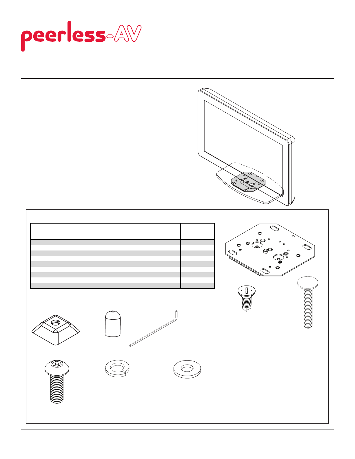
Installation and Assembly:
A
Desktop Swivel Mount for Philips 32HFL2082 and 40HFL2082 Displays
Model: HLG440-PH, HLG440-PH-Q10
Mounting to Desktop Surface
Mounting using Bolt Down Method
NOTE: Read entire instruction sheet before you start installation and assembly.
Parts List
Description Qty Part # Qty Part #
swivel plate assembly 1 090-1983 10 090-1983
B 10-32 x 3/8 flat head self drilling screw 3 560-2743 30 560-2743
C 1/4-20 x 1-3/4" thin head carriage bolt 2 560-1764 20 560-1764
D 1/4-20 slope nut 3 530-0035 23 530-0035
E plastic cap 2
F 4 mm allen wrench 1 560-9646 3 560-9646
G M5 x 20 mm socket pin screw 2 520-1065 20 520-1065
H #10 split lock washer 2 540-1035 20 540-1035
#10 flat washer 2 540-9400 20 540-9400
I
HLG440-PH HLG440-PH-Q10
590-1294
20
590-1294
A
B C
Before you start make sure all parts listed are included with your product.
D E
G
H I
F
1 of 4
ISSUED: 10-30-10 SHEET #:125-9164-2 09-14-11
Page 2
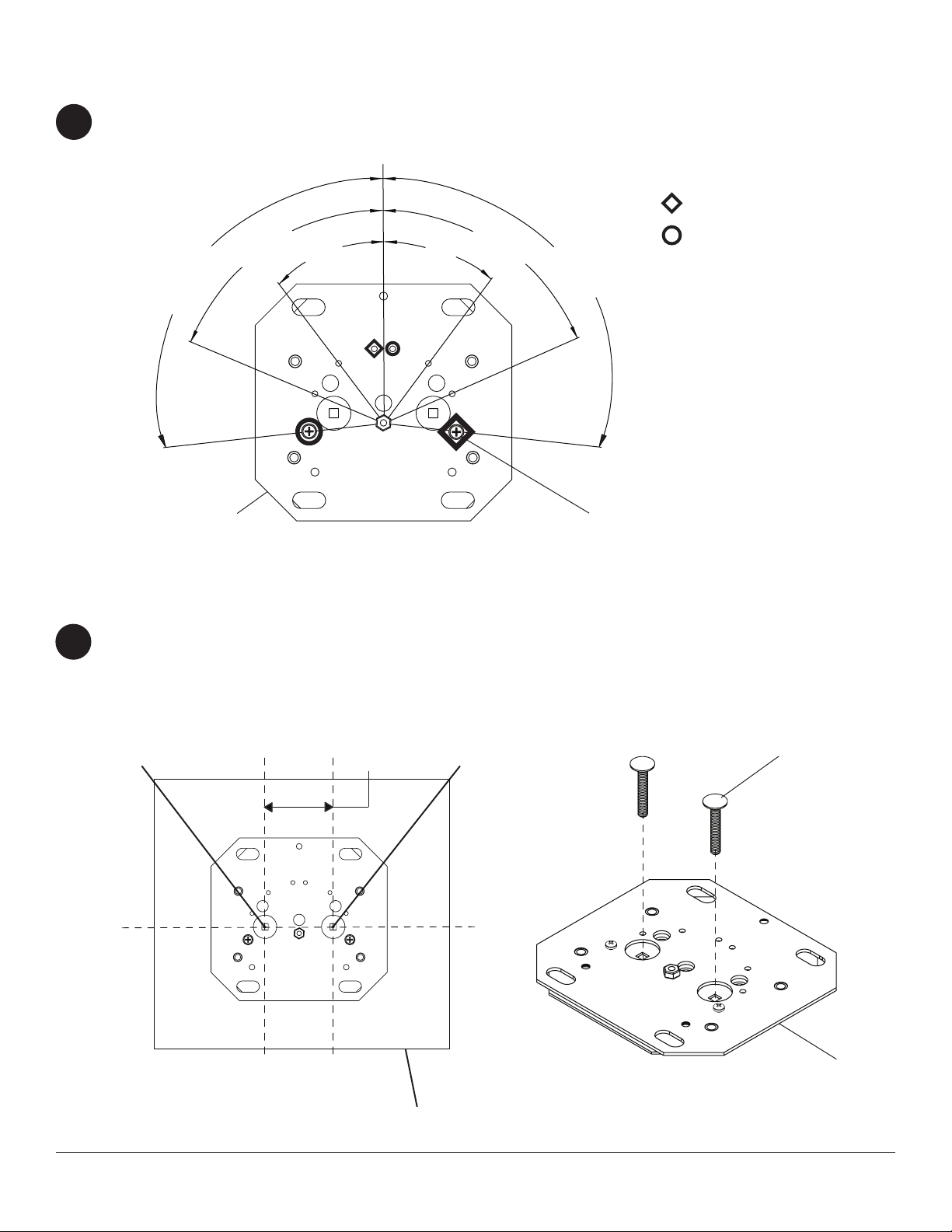
Mounting using Bolt Down Method
Choose swivel range below and identify swivel range holes of swivel plate assembly (A).
1
FRONT
60°
90°
90°
60°
30° 30°
USE HOLES TO LOCK SWIVEL
PLATE ASSEMBLY 90° FROM
CENTER
RIGHT SIDE
LEFT SIDE
A
Use swivel plate assembly (A) as a template to mark location of holes, point 1 and point 2, approximately 3" apart
2
on table. Drill two holes using a 1/4'' drill bit.
Place two 1/4-20 x 1-3/4" thin head carriage bolts (C) into slots of swivel plate assembly (A).
FRONT
POINT 1
3"
(76 mm)
POINT 2
SWIVEL RANGE HOLE
C
TABLE TOP
2 of 4
A
ISSUED: 10-30-10 SHEET #:125-9164-2 09-14-11
Page 3

Secure swivel plate assembly (A) to bottom of display base using three 10-32 x 3/8" at head self drilling screws (B)
3
in 32" or 42" orientation.
NOTE: Make sure that screws in display base align with slots and holes in swivel plate assembly (A)
as shown below.
DISPLAY
BASE SCREWS
FRONT
B
DISPLAY
BASE SCREWS
32" Display Base Attachment Location
A
ARROW INDICATES FRONT OF SWIVEL
PLATE ASSEMBLY
(note orientation of plate to base)
FRONT
.88"
42" Display Base Attachment Location
(note orientation of plate to base)
Hand tighten slope nut (D) through 1/4-20 x 1-3/4" thin head carriage bolt (C) until snug against bottom of desktop
4
surface. Thread another slope nut (D) upside-down, about two turns from rst slope nut (D). Insert an open box
wrench between both slope nuts (D) and tighten. NOTE: Avoid jamming both slope nuts (D) together, doing so
may make it difcult to remove slope nut used for tightening rst slope nut (D) as shown in g 4.1. After slope nut is
secure remove bottom slope nut and add plastic cap (E) as shown in gure 4.2. Repeat with remaining
1/4-20 x 1-3/4" thin head carriage bolt (C).
C
C
D
D
Detail 1
C
TIGHTENING
SLOPE NUT
E
BOTTOM OF DESKTOP
3 of 4
FIG 4.1 FIG 4.2
NOTE: Do not overtighten slope nut (D)
plate may distort
ISSUED: 10-30-10 SHEET #:125-9164-2 09-14-11
Page 4

Installation of Security Screws for Base to Display Attachment
32" Display Base (No Screws Required)
5
Attach display to base using hardware provided with display using the manufactures installation manual.
42" Display Base
Attach display to base using two M5 x 20 mm socket pin screws (G), two #10 split lock washers (H), and two
#10 at washers (I) into bottom holes as shown below. Tighten with 4 mm security allen wrench (F).
Use screws supplied with display for remaining holes.
42" Display Base Attachment Location
(note orientation of screws)
DISPLAY
G
I
H
DISPLAY BASE
NOTE: Display and base may appear
different than illustrated
4 of 4
All other brand and product names are trademarks or registered trademarks of their respective owners.
ISSUED: 10-30-10 SHEET #:125-9164-2 09-14-11
© 2010, Peerless Industries, Inc. All rights reserved.
 Loading...