

Page 1
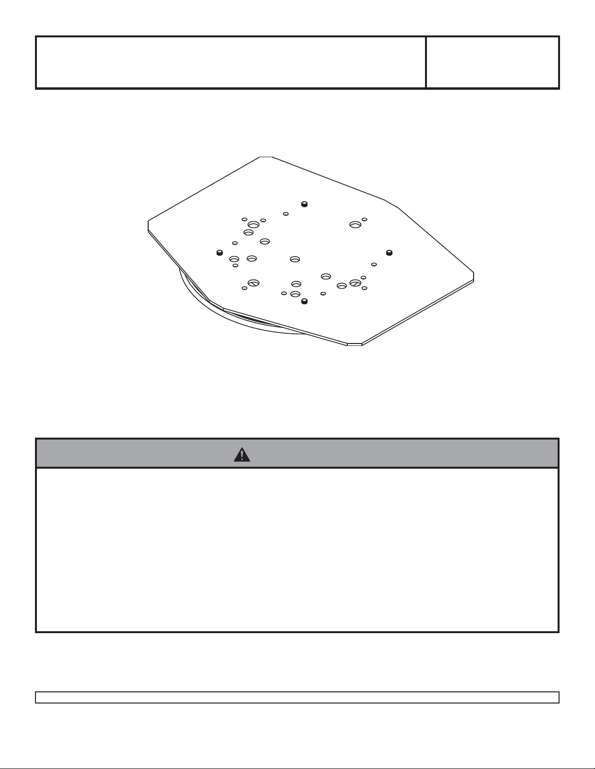
Installation and Assembly - Desktop Mount for
Sharp 32
IMPORTANT! Read entire instruction sheet before you start inst allation and assembly .
", 37" & 42" HT3 models
Models:HG442-HT3,
HG442-HT3-S
Maximum Load Capacity: 75 lb (34 kg)
WARNING
• Do not begin to install your Peerless product until you have read and understood the instructions and warnings contained in this Installation Sheet. If you have any questions regarding any of the instructions or warnings, please call
Peerless customer care at 1-800-865-2112.
• This product should only be installed by someone of good mechanical aptitude, has experience with basic building
construction, and fully understands these instructions.
• Make sure that the supporting surface will safely support the combined load of the equipment and all attached hardware and components.
• Never exceed the Maximum Load Capacity .
• Always use an assistant or mechanical lifting equipment to safely lift and position equipment.
• Tighten screws firmly , but do not overtighten. Overtightening can damage the items, greatly reducing their holding
power.
Tools Needed for Assembly
• 3M rubber and vinyl #80 spray adhesive (can be purchased at www .3mestore.com/62494949258.html)
• phillips screwdriver
1 of 7
Visit the Peerless Web Site at www.peerlessmounts.com For customer care call 1-800-729-0307 or 708-865-8870.
ISSUED: 02-28-08 SHEET #: 090-9143-2 04-28-08
Page 2
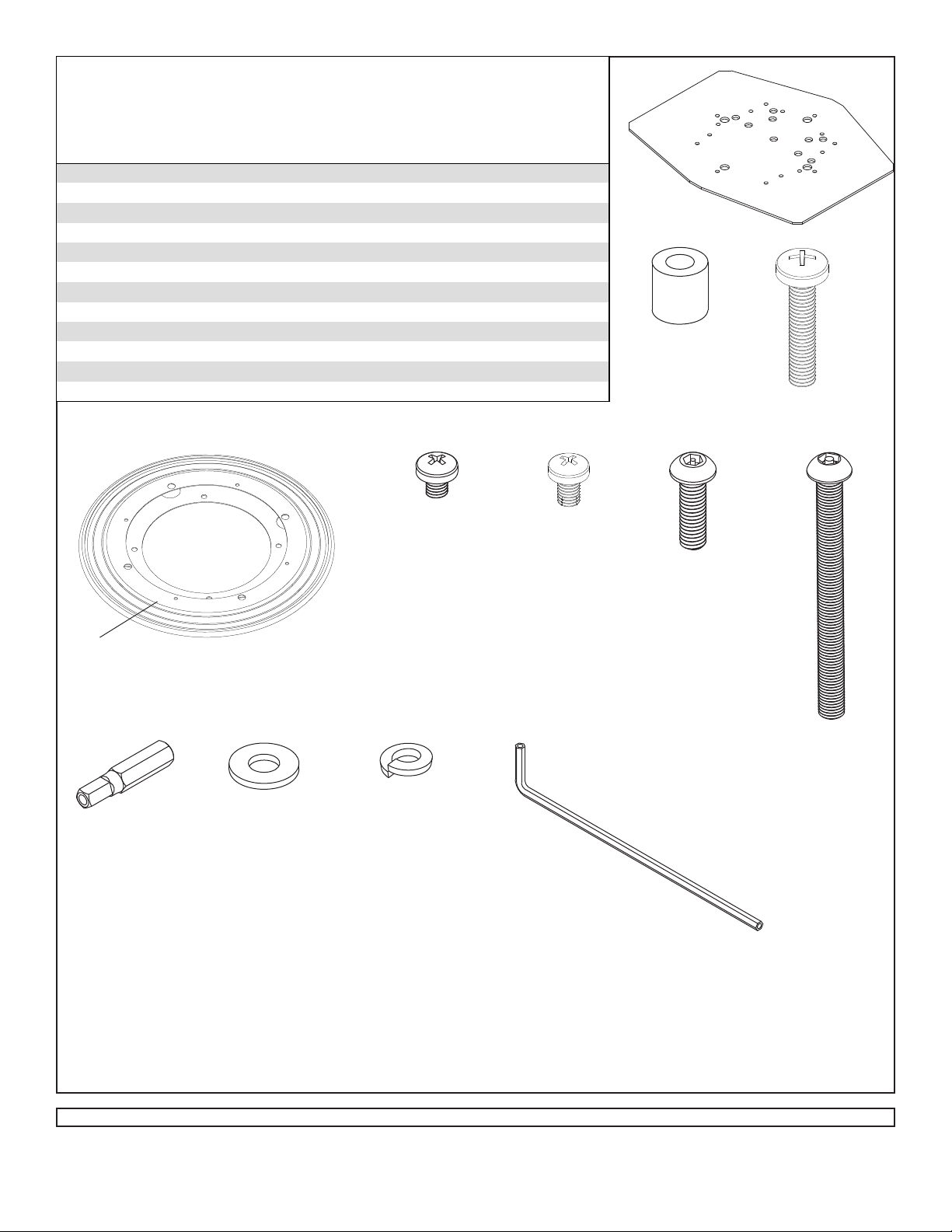
Bef ore you b egin, make s ure all part s shown are included with your product.
Parts List
HG442-HT3 HG442-HT3-S
Des cription
mounti ng plate 1 201-1553 201-1553
A
race as sembly 1 201-1555 201-1555
B
spacer
C
M6 x 30 mm screw
D
M5 x 6 mm type F phi l l i ps screw
E
M5 x 8 mm type F phi l l i ps screw
F
M6 x 20 mm socket pin screw 4 N/A 520-9554
G
M6 x 65 mm pent a-pi n s crew 4 N/A 520-1338
H
penta-driv er 1 N/A 520-9249
I
washer 4 N/A 540-9440
J
spl it washer 4 N/A 540-9402
K
4 mm security all en wrenc h 1 N/A 560-9646
L
Parts may appear slightly different than illustrated.
Qty. Part Number Part Number
5 540-1058 540-1058
5 510-9109 510-9109
4 520-9504 520-9504
2 520-1167 520-1167
A
C
D
B
TOP OF RACE
ASSEMBLY
I
E
F
GH
KLJ
2 of 7
Visit the Peerless Web Site at www.peerlessmounts.com For customer care call 1-800-729-0307 or 708-865-8870.
ISSUED: 02-28-08 SHEET #: 090-9143-2 04-28-08
Page 3
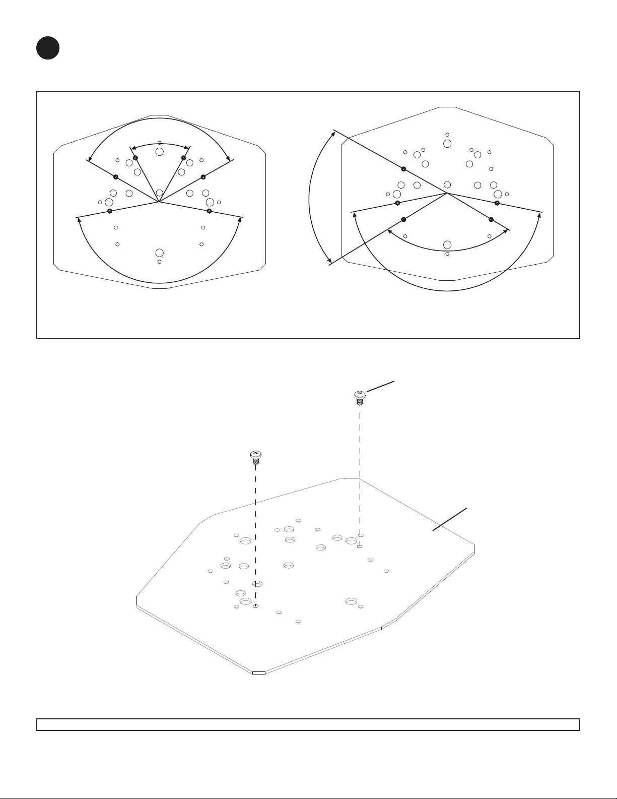
Swivel Restriction Option
Mounting plate (A) can be restricted to 60, 120 or 180 degrees of swivel. Locate the swivel hole patterns according
1
to screen model as shown in fig. 1.1. Insert two M5 x 8 mm screws (F) into holes on left and right side for desired
degree of swivel restriction as shown in fig. 1.2.
120°
60°
60°
°
120
180°
180°
Models: LC-32HT3U, LC-37HT3U Models: LC-42HT3U
fig 1.1
EXAMPLE: INSTALLED IN
F
HOLES FOR 180° SWIVEL
RESTRICTION
fig 1.2
A
3 of 7
Visit the Peerless Web Site at www.peerlessmounts.com For customer care call 1-800-729-0307 or 708-865-8870.
ISSUED: 02-28-08 SHEET #: 090-9143-2 04-28-08
Page 4

NOTE FOR LC-32HT3U: Remove rubber pads from bottom of LCD
stand that come in contact with mounting plate to ensure a flush
fit.
LCD STAND MAY APPEAR
DIFFERENT THAN ILLUSTRATED
2
Choose the correct mounting hole pattern shown in figure 2.1 for
attaching mounting plate (A) to LCD stand. Attach mounting plate
(A) to LCD stand using the appropriate number of M6 x 30 mm
phillips screws (D) and spacers (C) as shown in figure 2.2.
NOTE: Heads of M5 x 8 mm screws (F) must be between
mounting plate (A) and bottom of LCD stand as shown in detail 1.
Models: LC-32HT3U, LC-37HT3U
A
Models: LC-42HT3U
BACK OF
LCD STAND
C
A
fig. 2.2
D
LCD STAND
Rotate the swivel base so large holes in
3
race plate align with mounting holes in
swivel base.
fig. 2.1
A
MOUNTING HOLE
LARGE HOLE
A
F
C
D
DETAIL 1
B
4 of 7
Visit the Peerless Web Site at www.peerlessmounts.com For customer care call 1-800-729-0307 or 708-865-8870.
ISSUED: 02-28-08 SHEET #: 090-9143-2 04-28-08
Page 5

NOTE: Race assembly (B) and rivet must be in the correct orientation when installing. Rotate bottom of race
3- 1
assembly (B) until rivet is in the correct position for screen and desired swivel restriction as shown in as shown in
fig. 3.1 and 3.2. Place race assembly (B) onto mounting plate (A) while keeping it in the correct orientation. Att ach
race assembly (B) to mounting plate (A) using M5 x 6 mm type F phillips screws (E) as shown in fig. 3.3.
Rivet Location for Swivel Restriction
Models: LC-32HT3U, LC-37HT3U Models: LC-42HT3U
STAND MOUNTING
HOLES
B
A
RIVET
RIVET
RIVET
RIVET
180° 60° and120°
120° and 60°
fig. 3.1
A
180°
STAND MOUNTING
HOLES
B
fig. 3.2
E
NOTE: BOTTOM OF
B
EXAMPLE: RIVET IN
POSITION FOR 180°
SWIVEL RESTRICTION
RACE ASSEMBL Y
A
fig. 3.3
5 of 7
Visit the Peerless Web Site at www.peerlessmounts.com For customer care call 1-800-729-0307 or 708-865-8870.
ISSUED: 02-28-08 SHEET #: 090-9143-2 04-28-08
Page 6

WARNING
• Once race assembly (B) is attached to desk surface, swivel restriction/ orientation of screen cannot be adjusted.
Before applying vinyl #80 spray adhesive to desk surface,
3
place LCD stand right side up in desired location. Rivet
location on race assembly (B) must be in the middle of
swivel restriction range, refer to fig. 1.1 on page 3. Rotate
stand and verify that swivel restriction is correct.
NOTE: Once tape backing is removed be careful not to touch
the sticky surface of the tape with fingers, as this can cause
the tape to lose some of its holding power .
Clean desk surface with rubbing alcohol. Use 3M rubber and
vinyl #80 spray adhesive (not supplied) on the
surface area only. NOTE: S pray adhesive will not remove
easily. W ait at least 4 minutes to dry before removing t ape
backing from race assembly (B) and placing firmly on
surface. While placing the LCD stand/ desktop mount on
desk surface, bottom of race assembly must be held to
prevent the rivet from rotating out of place.
NOTE: Af ter application of tape on race assembly (B), the
bond strength will increase as the adhesive flows onto the
surface. At room tempurature, approximately 50% of the
ultimate strength will be achieved after 20 minutes, 90% after
24 hours, and 100% after 72 hours. In some cases, bond
strength can be achieved more quickly by exposure to
elevated tempuratures (e.g. 150°F [66°C] for 1 hour).
mounting
DRIED 3M RUBBER AND
VINYL #80 SPRA Y
ADHESIVE (not supplied)
LCD ST AND
DESK
SURFACE
6 of 7
Visit the Peerless Web Site at www.peerlessmounts.com For customer care call 1-800-729-0307 or 708-865-8870.
ISSUED: 02-28-08 SHEET #: 090-9143-2 04-28-08
Page 7

NOTE: Carefully place screen on LCD stand to reduce the change of displacing it before fully cured.
4
Slide screen onto LCD stand until screen mounting holes and LCD stand mounting holes align as shown in fig. 5.1.
Attach screen to LCD stand using fasteners that come with your screen.
Security Option: Attach screen to LCD st and using four M6 x 20 mm socket pin screws (G), used for the 32" and
37" screens or M6 x 65 mm penta-pin™ screws (H), used for the 42" screen with four split washers (K) and four flat
washers (J) as shown in figure 5.2. Tighten with 4 mm security allen wrench (L) or penta-pin™ driver (I).
Screen may appear
slightly different
than illustrated
J
K
LCD
ST AND
fig 5.1
G or H
MOUNTING SURFACE NOT
SHOWN FOR CLARITY
fig 5.2
7 of 7
Visit the Peerless Web Site at www.peerlessmounts.com For customer care call 1-800-729-0307 or 708-865-8870.
All other brand and product names are trademarks or registered trademarks of their respective owners.
ISSUED: 02-28-08 SHEET #: 090-9143-2 04-28-08
© 2008, Peerless Industries, Inc. All rights reserved.
 Loading...