


MRC 5000
MR C 5000
Form 3803 • Price $15.00
Edition 1 • © Dec. 1997
ONE AND TWO PEN CIRCULAR CHART RECORDING CONTROLLER
Installation, Wiring, Operation Manual
THE PARTLOW-WEST COMPANY
TWO CAMPION ROAD • NEW HARTFORD, NY 13413 USA
1-800-866-6659 • 1-315-797-2222 • FAX 1-315-797-0403
Brand

2
nformation in this installation, wiring, and operation manual is subject to change
without notice. One manual is provided with each instrument at the time of ship-
ment. Extra copies are available at the price published on the front cover.
Copyright © December 1997, The Partlow-West Company, all rights reserved. No part of
this publication may be reproduced, transmitted, transcribed or stored in a retrieval sys-
tem, or translated into any language in any form by any means without the written permis-
sion of The Partlow-West Company.
This is the First Edition of the MRC 5000 Recording Controller Manual. It was written and
produced entirely on a desk-top-publishing system. Disk versions are available by written
request to The Partlow-West Company Marketing Communications Department.
We are glad you decided to open this manual. It is written so that you can take full advan-
tage of the features of your new MRC 5000 microbased chart recording controller.
It is strongly recommended that Partlow Brand equipped applications incorporate a high
or low limit protective device which will shut down the equipment at a preset process
condition in order to preclude possible damage to property or products.
I
NO TE:

3
TABLE OF CONTENTS
PAGE NUMBER
SECTION 1 - OVERVIEW 5
1.1 Display 5
1.2 Control 5
1.3 Alarms 5
1.4 Digital Communications 5
1.5 Power Input 5
SECTION 2 - INSTALLATION & WIRING 6
2.1 Unpacking 6
2.2 Location / Mounting 6
2.3 Preparation for Wiring 8
2.4 Wiring Connections 11
SECTION 3 - NORMAL OPERATION 15
3.1 Changing The Chart 15
3.2 Control Output Settings 15
3.3 Alarm Settings 16
3.4 High/Low Limits 16
SECTION 4 - RECORDER SETUP, TEST, AND CALIBRATION 16
4.1 Hardware Selections - Input Jumper Positions 17
4.2 Recorder Programming 17
4.3 Test Mode 20
SECTION 5 - RECORDER CALIBRATION MODE 21
5.1 Input Calibration 21
5.2 Chart/Pen Calibration 22
SECTION 6 - MODEL NUMBER CHANGES 23
APPENDICES
A - Model Number Hardware Matrix Details 24
B - Specifications 25
Warranty 31

4
FIGURES
Figure 2-1A Panel Mounting 6
Figure 2-1B Surface Mounting 7
FIgure 2-1C Adaptor Plate 7
Figure 2-2 Noise Suppression 9
Figure 2-3 Noise Suppression 9
Figure 2-4 Board and Terminal Locations 11
Figure 2-5A AC Power Input Wiring-Standard Voltage 12
Figure 2-5B Power Wiring-Low Voltage 12
Figure 2-6 Input Signal Wiring 12
Figure 2-7 Relay Output Wiring 13
Figure 2-8 Communications Wiring 13
Figure 2-9A Transmitter Power Supply (One Transmitter) 14
Figure 2-9B Transmitter Power Supply (Two Transmitters) 14

5
Section 1 Overview
This instrument records process trend lines, one or two pens, on a 10 inch circular chart. As an option, up to two alarm points
are provided for each of the two pens.
This recorder will accept J, K, T, R, and S Thermocouples and RTD inputs, as well as typical Millivolt, Milliamp (4-20mA) and
Volt inputs, (up to 5 volts).
1.1 DISPLAY
Process values for each pen can be displayed on the .56" LED display, or the display can be blanked. In the latter case, the
display is used only for programming and setting alarm points.
1.2 CONTROL
The instrument can be provided with relay control outputs which can be programmed for on-off control capability.
1.3 ALARMS
Two optional alarm output relays, with SPDT contacts, are available for each pen. Each alarm is also configurable as a
latching, limit device. In this case, a manual reset button is required and included when the High/Low Limit option is ordered.
1.4 DIGITAL COMMUNICATIONS
An optional, RS-485 digital communications port is available that utilizes the standard MODBUS RTU protocol.
1.5 POWER INPUT
The standard recorder will operate on input power over the range of 90-264 VAC, 50-60 Hz, without any modifications. A low
power voltage option (20-50 VAC or 22-65 VDC) is also available. All Low Voltage option recorders are clearly identified as
such by a label near the power wiring terminal block.
6
Section 2 Installation and Wiring
Read these instructions completely and carefully before proceeding with the installation and operation of this recorder.
Electrical code requirements and safety standards should be observed. Installation should be performed by qualified person-
nel only.
Caution: The standard recorder will accept a power input over the range of 90-264 VAC. There is a special low power
voltage option that is available. Please verify the AC input power required by the recorder before proceeding with the
installation. The power required is listed in the Model/Serial number label affixed to the platen in the upper left hand
corner.
2.1 UNPACKING
Remove the recorder from the carton and inspect for any damage due to shipment. If any damage is noted, report and file a
claim with the carrier. Write the model number and serial number of the instrument on the inside front cover of this operation
manual for future reference.
2.2 LOCATION / MOUNTING
Locate the instrument away from excessive moisture, oil, dust and vibration. Do not subject the instrument to operating
temperatures outside of the 0 to 55°C (32 to 131°F) range.
The panel where the instrument will be mounted must provide rigid support for the approximate 7 lb. weight of the instrument.
Adjacent instruments may be mounted within a minimum of 2 inches horizontally and 3 inches vertically, providing that proper
panel support is provided.
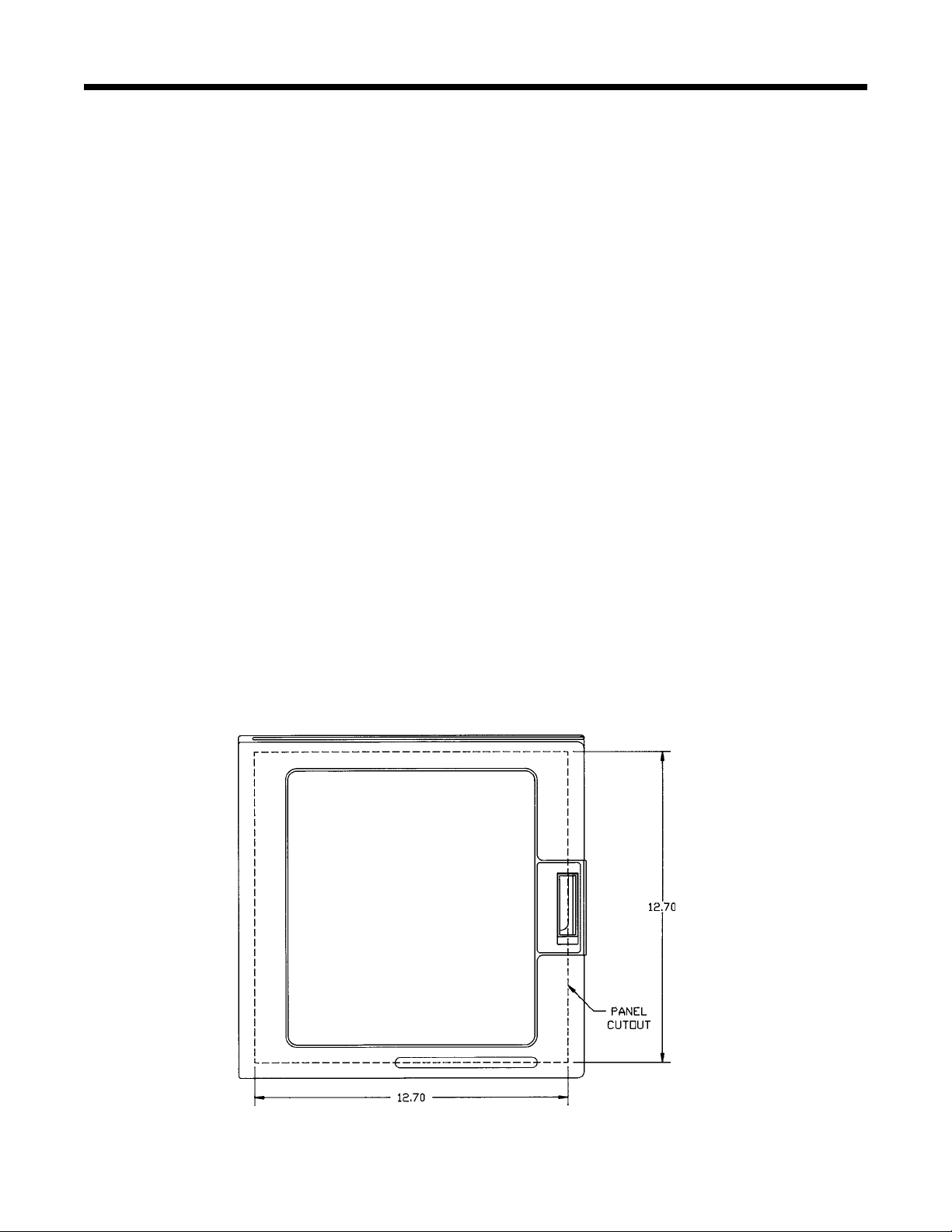
PANEL MOUNTING:
1. Remove the mounting brackets attached to the recorder upon receipt.
2. Cut panel opening to the dimensions illustrated in Figure 2-1A.
3. Insert the recorder in the panel opening. Reattach the mounting brackets to the side of the recorder with the mounting ears
facing the back of the panel. Adjust the mounting brackets so they fit snugly against the panel, and then tighten.
PANEL MOUNTING HARDWARE REQUIRED: (provided with instrument)
(1) set mounting brackets - mounted to the recorder
(1) set mounting screws - mounted to the recorder
FIGURE 2-1A
±0.06
±0.06
7
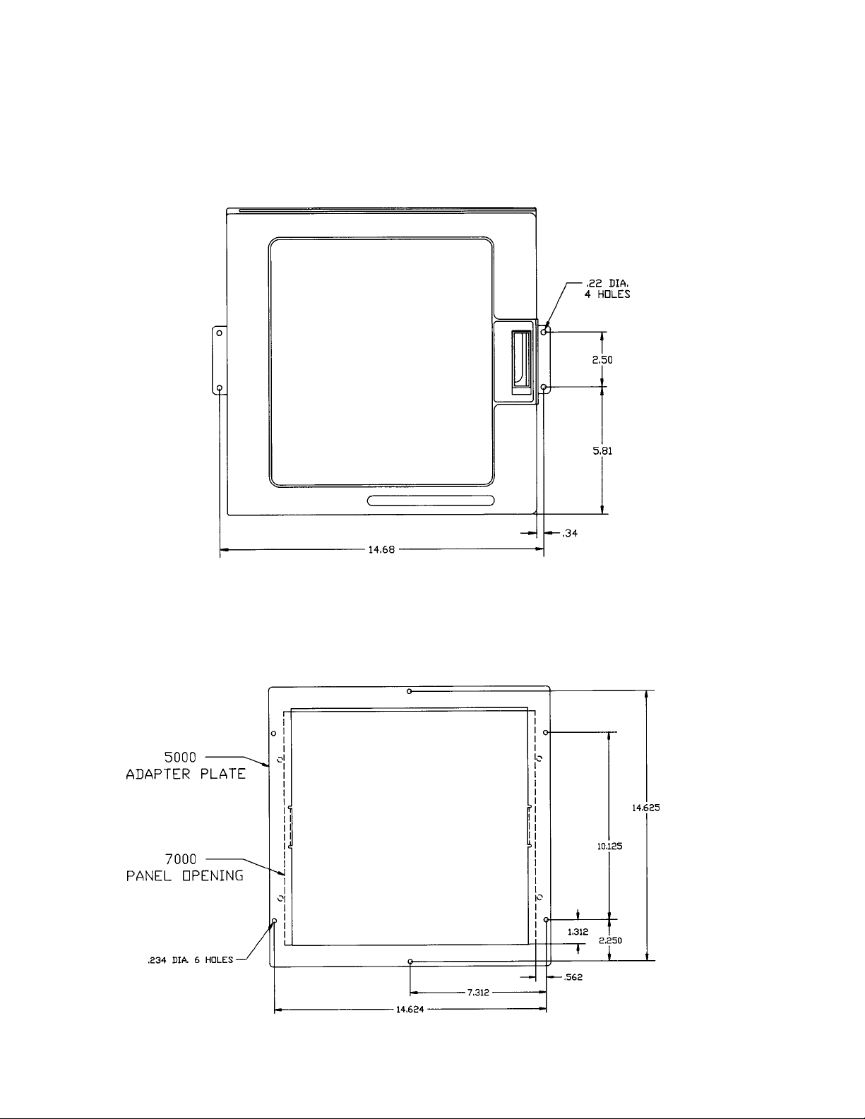
SURFACE MOUNTING:
1. Loosen the mounting brackets attached to the recorder and flip their position so the ears are flush with the back of he
recorder. Fasten the recorder to the surface using the appropriate fasteners (#10 screws or nuts and bolts) depending on the
surface material.
2. As an alternative, remove the brackets, attach them to the surface, and then attach the recorder to the brackets.
FIGURE 2-1B
RETROFIT:
Note: An Adapter Plate is available (P/N 50033301) that allows the recorder to retrofit with the Partlow MRC 7000 and ARC
4100 recorders. Figure 2-1C shows the adapter plate relative to the MRC 7000/ARC 4100 cutout. The Adapter Plate includes
ears that attach to the sides of the recorder.
FIGURE 2-1C
Use #10 screws

8
2.3 PREPARATION FOR WIRING
Electrical noise interference is a phenomenon typical of industrial environments. Use the following guidelines which are
generally used to minimize the effect of electrical noise on instrumentation in general.
2.3.1 WIRING GUIDELINES
Listed below are some of the common sources of electrical noise in the industrial environment:
• Ignition Transformers
• Arc Welders
• Mechanical contact relay(s)
• Solenoids
Before using any instrument near the devices listed, the instructions below should be followed:
1. If the recorder is to be mounted in the same panel as any of the listed devices, separate them by the largest distance
possible.
2. If possible, replace electromechanical relay(s) with solid state relays.
3. Consider using a separate isolation transformer to power the recorder and any other instrumentation in the panel. The
transformer will serve to isolate the recorder from noise found on the AC power lines.
4. If the recorder is being installed on existing equipment, existing wiring should be inspected to insure that good wiring
practices have been followed.
5. Connect a good earth ground to the recorder chassis ground connection. To verify this, take a resistive measurement
from the instrument chassis to the nearest metal water pipe or proven earth ground. The reading should not exceed 100
ohms. Each instrument should have a dedicated earth ground. Do not chain link multiple instrument groundwires.
6. AC neutral should be at or near ground potential. To verify this, measure the AC voltage between neutral and ground.
The reading should be no more than 50 millivolts. If greater, the secondary of the transformer feeding the recorder should be
checked out by an electrician.
7. Wire Isolation/Segregation - this recorder is designed to promote proper separation of the wiring groups that connect to it.
The AC power terminals are located near the top of the instrument. The input signal terminals are located in the middle
section of the main board and the output alarm relay connections are on a separate board in the lower right hand corner of
the instrument.
8. Input Signal Wiring
-
Shielded cable helps eliminate electrical noise being induced on the wires. All input wires should be
run with shielded cable. Connection lead length should be kept as short as possible. The shield should be grounded at one
end only. The preferred grounding location is at the sensor, transmitter or transducer.
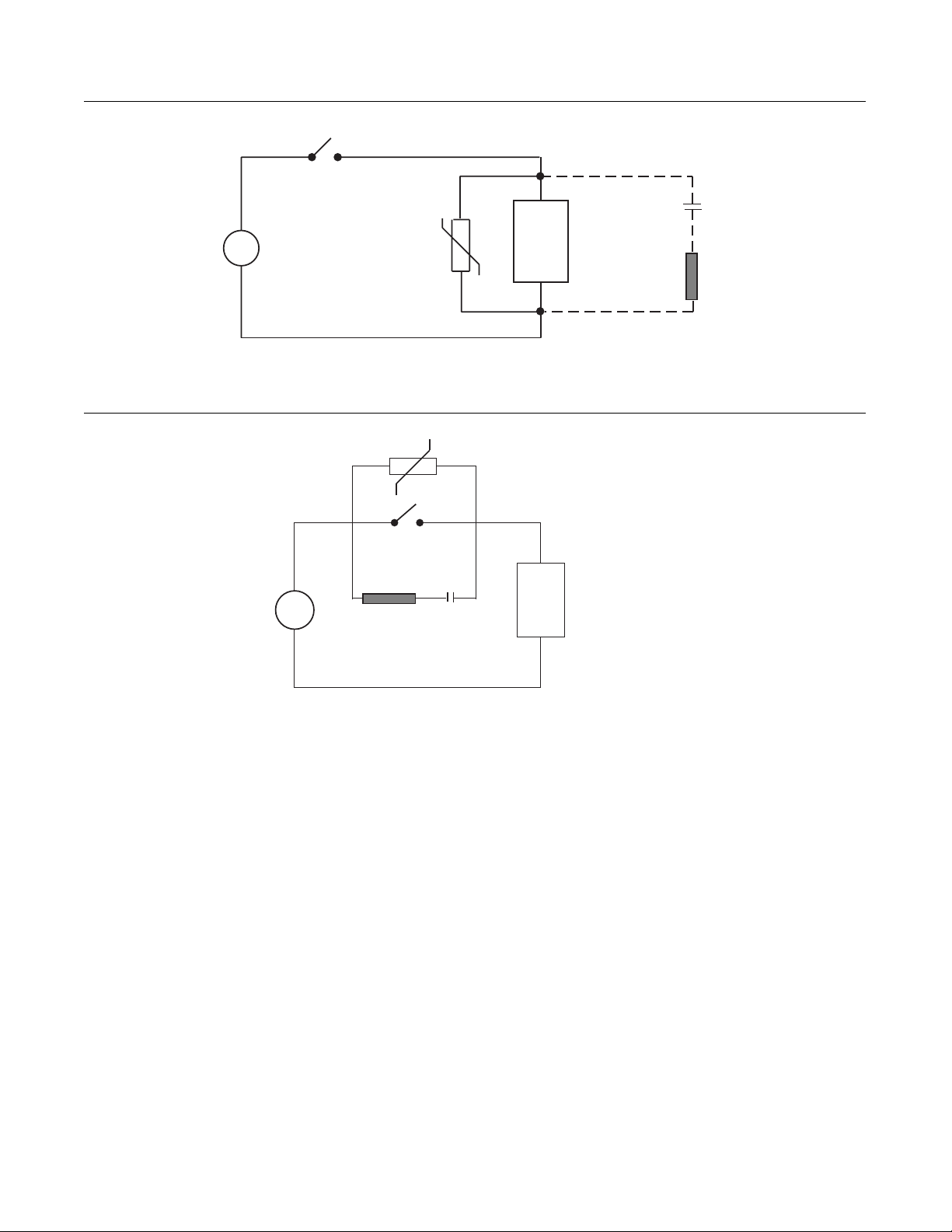
9. For severe levels of electrical noise, it may be necessary to suppress the noise at its source. Many manufacturers of
relays, contractors, etc. supply "surge suppressors" which mount on the noise source. For those devices that do not have
surge suppressors supplied, RC (resistance-capacitance) networks and/or MOVs (metal oxide varistors) may be added.
Inductive Loads - MOVs are recommended for transient suppression for inductive loads, and should be connected in parallel
and as close as possible to the load. See Figure 2-2. Additional protection may be provided by adding an RC network across
the load.
Contacts - Arcing may occur across contacts (relays or switches) when they open and close. This results in electrical noise
as well as damage to the contacts. Connecting an RC network, properly sized, in parallel, can eliminate this problem. See
Figure 2-3.
For circuits up to 3 amps, a combination of a 220 ohm resistor and 0.5 microfarad capacitor (1000 volts) is recommended.
For circuits from 3 to 5 amps, connect two of these in parallel. The resistor should be 1/4 watt or 1 watt for 115 VAC or
230VAC circuits, respectively.
9
FIGURE 2-2
FIGURE 2-3
2.3.1 SENSOR PLACEMENT
If the input probe will be subjected to corrosive or abrasive conditions, it should be protected by the appropriate thermowell.
The probe should be positioned to reflect the true process temperature:
In liquid media - the most agitated area
In air - the best circulated area
For thermocouple sensors, the lead resistance should not exceed 300 ohms. If this is exceeded, recorder accuracy could be
affected. To determine the temperature error caused by lead length resistance, use the following equation:
Terr = TCe x L where; TCe = temperature error in °F or °C per 1000 feet
L = length of lead wire in thousands of feet
A.C.
MOV
Inductive
Load
C
R
A.C.
MOV
R
Inductive
Load
C

10
TABLE 1
Temperature error in °C per 1000 feet of Lead wire
AWG Thermocouple Type:
No. J K T R S
10 0.03 0.09 0.04 0.10 0.11
12 0.05 0.13 0.06 0.16 0.16
14 0.09 0.21 0.10 0.27 0.26
16 0.14 0.34 0.15 0.41 0.42
18 0.22 0.55 0.25 0.68 0.68
20 0.36 0.86 0.39 1.08 1.09
24 0.88 2.19 0.99 2.72 2.73
TABLE 2
Temperature Error in °F per 1000 feet of Lead wire
AWG Thermocouple Type:
No. J K T R S
10 0.06 0.15 0.07 0.18 0.19
12 0.10 0.24 0.11 0.30 0.30
14 0.16 0.39 0.18 0.48 0.48
16 0.25 0.61 0.28 0.75 0.75
18 0.40 0.99 0.45 1.22 1.23
20 0.64 1.55 0.71 1.94 1.96
24 1.58 3.94 1.78 4.89 4.91
For 3 wire RTDs, the instrument can virtually eliminate all lead wire resistance error.
Two wire RTDs should be used only with lead lengths less than 10 feet, unless special input calibration is performed using the
iCor (Input Correction) capability. (See Section 4 for setting iCor.) To determine the temperature error resulting from the lead
length resistance, use the following equation:
Terr = TRe x L where; TRe = temperature error in °C or °F per 1000 feet
L = length of lead wire in thousands of feet
TABLE 3 2 Wire RTD
AWG No. Error °C Error °F
10 +/-5.32 +/-9.31
12 +/-9.31 +/-14.6
14 +/-13.3 +/-23.9
16 +/-21.3 +/-38.6
18 +/-34.6 +/-61.2
20 +/-54.5 +/-97.1
24 +/-86.5 +/-155.6
 Loading...