


MIC 1161
1/16 DIN MICROBASED LIMIT CONTROLLER
OPERATORS MANUAL
FORM 3535
EDITION 1
© JAN. 1995 PRICE $10.00
Brand

Information in this installation, wiring, and operation manual is subject to change without notice. One manual is provided with each instrument at the time of shipment. Extra copies are available at the price published on the front cover.
Copyright © January 1995, The Partlow Corporation, all rights reserved. No part of this publication may be reproduced, transmitted, transcribed or stored in a retrieval system, or translated into any language in any form by any means without the written permission of the Partlow Corporation.
This is the First Edition of the MIC 1161 manual. It was written and produced entirely on a desk-top-publishing system. Disk versions are available by written request to the Partlow Publications Department.
We are glad you decided to open this manual. It is written so that you can take full advantage of the features of your new MIC 1161 limit controller.
NOTE:
It is strongly recommended that Partlow equipped applications incorporate a high or low limit protective device which will shut down the equipment at a preset process condition in order to preclude possible damage to property or products.
!
THE INTERNATIONAL HAZARD SYMBOL IS INSCRIBED ADJACENT TO THE REAR CONNECTION TERMINALS. IT IS IMPORTANT TO READ THIS MANUAL BEFORE INSTALLING OR COMMISSIONING THE UNIT.
MIC 1161 Manual |
2 |

Table of Contents
Section 1 - General |
Page |
|
1.1 |
Product Description |
5 |
Section 2 - Installation & Wiring |
|
|
2.1 |
Installation & Wiring |
7 |
2.2 |
Preparations for Wiring |
9 |
2.3 |
Input Connections |
17 |
2.4 |
Output Connections |
19 |
Section 3 - Configuration & Operation |
|
|
3.1 |
Operation |
21 |
3.2 |
Configuration |
26 |
Appendices |
|
|
A - Glossary of Terms |
32 |
|
B - Exploded View & Board Layout |
36 |
|
|
Figure B-1 Exploded View |
36 |
|
Figure B-2 CPU PWA |
37 |
|
Figure B-3 Option PWA DC Output 3 |
38 |
C - Hardware Definition Code |
39 |
|
D - Input Range Codes |
41 |
|
E - Specifications |
43 |
|
F - Model Number Hardware Matrix |
47 |
|
G- Software Reference |
48 |
|
3 |
MIC 1161 Manual |

Figures & Tables
Figure 1-1 |
Display Illustration |
6 |
Figure 2-1 |
Panel Cut-Out Dimensions |
8 |
Figure 2-2 |
Main Dimensions |
8 |
Figure 2-3 |
Panel Mounting |
9 |
Figure 2-4 |
Noise Suppression |
12 |
Figure 2-5 |
Noise Suppression |
12 |
Figure 2-6 |
Wiring |
16 |
Figure 2-7 |
AC Power |
17 |
Figure 2-8 |
Thermocouple Input |
17 |
Figure 2-9 |
RTD Input |
17 |
Figure 2-10 |
Volt, mV mADC Input |
18 |
Figure 2-11 |
Remote Reset Input |
18 |
Figure 2-12 |
Remote Digital Connections |
19 |
Figure 2-13 |
Relay Output 1 |
19 |
Figure 2-14 |
Relay Output 2 |
19 |
Figure 2-15 |
Relay Output 3 |
20 |
Figure 2-16 |
mADC Output 3 |
20 |
Table 3-1 |
Enable Mode Configuration Procedures |
27 |
Table 3-2 |
Program Mode Configuration Procedures |
28 |
Table 3-3 |
Set-Up Mode Configuration Procedures |
30 |
MIC 1161 Manual |
4 |

Product Description 1.1
1.1.1 GENERAL
This instrument is a microprocessor based single loop limit controller, user configurable to either High Limit type or Low Limit type.
The input is user configurable to directly connect to either thermocouple, RTD, mVDC, VDC or mADC inputs. The instrument can operate from a 90-264 VAC, 50/60 HZ power supply.
Features include fail safe operation (relay de-energized by the limit exceeded condition), front panel Reset switch, time limit exceeded display and maximum/minimum tracking of excursions of the process variable.
1.1.2 DISPLAYS
Each instrument is provided with dual displays and status indicators as shown in Figure 1-1. The upper display displays the value of the process variable. The lower display displays the setpoint value. Status indication is as shown in Figure 1-1, page 6.
1.1.3 ALARMS
Alarm indication is standard on all instruments. Up to two alarm outputs are possible. Alarm type may be set as Process Direct or Reverse (high or low), Logical Combination of the two alarms and Annunciator Direct or Reverse. Alarm status is indicated by LED.
1.1.4 PROCESS VARIABLE/SETPOINT VALUE RE-TRANSMISSION OUTPUT
If the instrument is specified with this option, this output may be scaled over any desired range and re-transmitted.
5 |
MIC 1161 Manual |
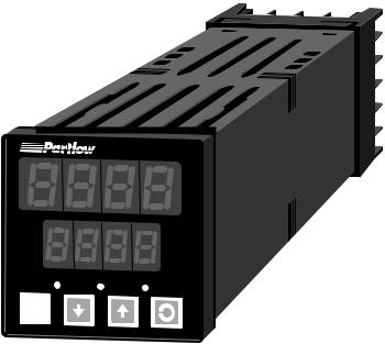
FIGURE 1-1
Keys and Indicators
TOP
1161
OUT EXCEED ALM
RESET
MIC 1161 Manual |
6 |

Installation and Wiring 2.1
Electrical code requirements and safety standards should be observed and installation performed by qualified personnel.
The electronic components of the instrument may be removed from the housing during installation. To remove the components, grip the side edges of the front panel and pull the instrument forward. During re-installa- tion, the vertically mounted circuit boards should be properly aligned in the housing.
Ensure that the instrument is correctly orientated. A stop will operate if an attempt is made to insert the instrument incorrectly. CAUTION: This stop can be over-ridden with enough force. If in doubt, check orientation again!
Recommended panel opening sizes are illustrated in Figure 2-1, page 8. After the opening is properly cut, insert the instrument into the panel opening. Ensure that the panel gasket is not distorted and that the instrument is positioned squarely against the panel. Slide the mounting clamp into place on the instrument (see Figure 2-3, page 9) and push it forward until it is firmly in contact with the rear face of the mounting panel.
Note: The mounting clamp tongues may engage either on the sides or the top/bottom of the instrument housing. Therefore, when installing several instruments side-by-side in one cut out, use the ratchets on the top/bottom faces.
7 |
MIC 1161 Manual |

FIGURE 2-1
Panel Cut-Out Dimensions
 45 mm +0.5 - 0.0
 (1.77" +.024 - .000)
PANEL
45 mm +0.5 - 0.0 CUTOUT (1.77" +.024 - .000)
SIZE
FIGURE 2-2
Main Dimensions
 110 mm (4.33 in.)
48 mm
(1.89 in)
Side View
 10 mm (0.39 in.)
48 mm (1.89 in.)
MIC 1161 Manual |
8 |
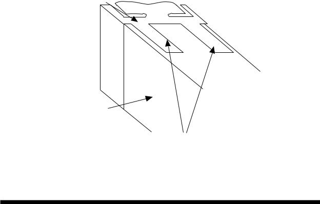
FIGURE 2-3
Panel Mounting the Controller
Mounting Clamp
Controller Housing
Tongues on mounting clamp engage in ratchet slots on controller housing
Preparation for Wiring 2.2
2.2.1 WIRING GUIDELINES
Electrical noise is a phenomenon typical of industrial environments. The following are guidelines that must be followed to minimize the effect of noise upon any instrumentation.
2.2.1.1 INSTALLATION CONSIDERATIONS
Listed below are some of the common sources of electrical noise in the industrial environment:
•Ignition Transformers
•Arc Welders
•Mechanical contact relay(s)
•Solenoids
9 |
MIC 1161 Manual |
Before using any instrument near the device listed, the instructions below should be followed:
1.If the instrument is to be mounted in the same panel as any of the listed devices, separate them by the largest distance possible. For maximum electrical noise reduction, the noise generating devices should be mounted in a separate enclosure.
2.If possible, eliminate mechanical contact relay(s) and replace with solid state relays. If a mechanical relay being powered by an instrument output device cannot be replaced, a solid state relay can be used to isolate the instrument.
3.A separate isolation transformer to feed only instrumentation should be considered. The transformer can isolate the instrument from noise found on the AC power input.
4.If the instrument is being installed on existing equipment, the wiring in the area should be checked to insure that good wiring practices have been followed.
2.2.1.2AC POWER WIRING
Neutral (For 115 VAC)
It is good practice to assure that the AC neutral is at or near ground potential. To verify this, a voltmeter check between neutral and ground should be done. On the AC range, the reading should not be more than 50 millivolts. If it is greater than this amount, the secondary of this AC transformer supplying the instrument should be checked by an electrician. A proper neutral will help ensure maximum performance from the instrument.
2.2.1.3WIRE ISOLATION
Four voltage levels of input and output wiring may be used with the unit:
•Analog input or output (i.e. thermocouple, RTD, VDC, mVDC, or mADC)
•SPDT Relays
•AC power
The only wires that should run together are those of the same category. If they need to be run parallel with any of the other lines, maintain a minimum 6 inch space between the wires. If wires must cross each other, do so at 90 degrees. This will minimize the contact with each other and reduces “cross talk”.
MIC 1161 Manual |
10 |
“Cross Talk” is due to the EMF (Electro Magnetic Flux) emitted by a wire as current passes through it. This EMF can be picked up by other wires running in the same bundle or conduit.
In applications where a High Voltage Transformer is used (i.e. ignition systems) the secondary of the transformer should be isolated from all other cables.
This instrument has been designed to operate in noisy environments, however, in some cases even with proper wiring it may be necessary to suppress the noise at its source.
2.2.1.4 USE OF SHIELDED CABLE
Shielded cable helps eliminate electrical noise being induced on the wires. All analog signals should be run with shielded cable. Connection lead length should be kept as short as possible, keeping the wires protected by the shielding. The shield should be grounded at one end only. The preferred grounding location is the sensor, transmitter or transducer.
2.2.1.5 NOISE SUPPRESSION AT THE SOURCE
Usually when good wiring practices are followed no further noise protection is necessary. Sometimes in severe electrical environments, the amount of noise is so great that it has to be suppressed at the source. Many manufacturers of relays, contactors, etc. supply “surge suppressors” which mount on the noise source.
For those devices that do not have surge suppressors supplied, RC (resis- tance-capacitance) networks and/or MOV (metal oxide varistors) may be added.
Inductive Coils - MOV’s are recommended for transient suppression in inductive coils connected in parallel and as close as possible to the coil. See Figure 2-4, page 12. Additional protection may be provided by adding an RC network across the MOV.
11 |
MIC 1161 Manual |
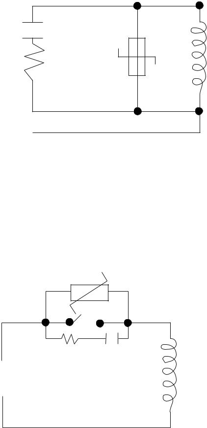
FIGURE 2-4
0.5 mfd 1000V
220 |
Coil |
|
|
ohms |
|
115V 1/4W
230V 1W
Contacts - Arcing may occur across contacts when the contact opens and closes. This results in electrical noise as well as damage to the contacts. Connecting a RC network properly sized can eliminate this arc.
For circuits up to 3 amps, a combination of a 47 ohm resistor and 0.1 microfarad capacitor (1000 volts) is recommended. For circuits from 3 to 5 amps, connect 2 of these in parallel. See Figure 2-5.
FIGURE 2-5
MOV
R C
Inductive
Coil
MIC 1161 Manual |
12 |
2.2.2 SENSOR PLACEMENT (Thermocouple or RTD)
Two wire RTD’s should be used only with lead lengths less than 10 feet.
If the temperature probe is to be subjected to corrosive or abrasive conditions, it should be protected by the appropriate thermowell. The probe should be positioned to reflect true process temperature:
In liquid media - the most agitated area
In air - the best circulated area
THERMOCOUPLE LEAD RESISTANCE
Thermocouple lead length can affect instrument accuracy since the size (gauge) and the length of the wire affect lead resistance.
To determine the temperature error resulting from the lead length resistance, use the following equation:
Terr = TLe * L |
where; |
TLe = value from appropriate table |
|
|
|||||||
|
|
|
|
|
L = length of leadwire in thousands of feet |
||||||
TABLE 1 |
|
|
|
|
|
|
|
|
|
||
|
|
|
|
|
|
||||||
Temperature error in °C per 1000 feet of leadwire |
|
|
|
||||||||
|
AWG |
Thermocouple Type: |
|
|
|
|
|
|
|||
|
NO. |
J |
K |
T |
R |
S |
E |
B |
N |
C |
|
|
10 |
.34 |
.85 |
.38 |
1.02 |
1.06 |
.58 |
7.00 |
1.47 |
1.26 |
|
12 |
.54 |
1.34 |
.61 |
1.65 |
1.65 |
.91 |
11.00 |
2.34 |
2.03 |
|
|
14 |
.87 |
2.15 |
.97 |
2.67 |
2.65 |
1.46 |
17.50 |
3.72 |
3.19 |
|
|
16 |
1.37 |
3.38 |
1.54 |
4.15 |
4.18 |
2.30 |
27.75 |
5.91 |
5.05 |
|
|
18 |
2.22 |
5.50 |
2.50 |
6.76 |
6.82 |
3.73 |
44.25 |
9.40 |
8.13 |
|
|
20 |
3.57 |
8.62 |
3.92 |
10.80 |
10.88 |
5.89 |
70.50 |
14.94 |
12.91 |
|
|
24 |
8.78 |
21.91 |
9.91 |
27.16 |
27.29 |
14.83 |
178.25 |
37.80 32.64 |
|
||
See next page for Table 2
13 |
MIC 1161 Manual |

TABLE 2
Temperature error in °F per 1000 feet of leadwire
|
AWG |
Thermocouple Type: |
|
|
|
|
|
|||
|
NO. |
J |
K |
T |
R |
S |
E |
B |
N |
C |
|
10 |
.61 |
1.54 |
.69 |
1.84 |
1.91 |
1.04 |
12.60 |
2.65 |
2.27 |
12 |
.97 |
2.41 |
1.09 |
2.97 |
2.96 |
1.64 |
19.80 |
4.21 |
3.66 |
|
14 |
1.57 |
3.86 |
1.75 |
4.81 |
4.76 |
2.63 |
31.50 |
6.69 |
5.74 |
|
16 |
2.47 |
6.09 |
2.77 |
7.47 |
7.52 |
4.14 |
49.95 |
10.64 |
9.10 |
|
18 |
4.00 |
9.90 |
4.50 |
12.17 |
12.28 |
6.72 |
79.95 |
10.64 |
9.10 |
|
20 |
6.43 |
15.51 |
7.06 |
19.43 |
19.59 |
10.61 |
126.90 |
26.89 |
23.24 |
|
24 |
15.80 39.44 17.83 48.89 |
49.13 |
26.70 |
320.85 |
68.03 |
58.75 |
||||
Example:
A instrument is to be located in a control room 660 feet away from the process. Using 16 AWG, type J thermocouple, how much error is induced?
Terr = TLe * L
TLe = 2.47 (°F per 1000 ft) from Table 2
Terr = 2.47 (°F/1000 ft) * 660 ft
Terr = 1.6°F
RTD LEAD RESISTANCE
RTD lead length can affect instrument accuracy, since the size (gauge) and length of the wire affect lead resistance.
To determine the temperature error resulting from the lead length resistance, use the following equation:
Terr = TLe * L where; |
TLe = value from Table 3 if 3 wire RTD or |
|
Table 4 if 2 wire RTD |
|
L = length of lead wire in thousands of feet |
MIC 1161 Manual |
14 |
TABLE 3 3 Wire RTD
|
AWG NO. |
Error °C |
Error °F |
|
10 |
± 0.04 |
± 0.07 |
|
12 |
± 0.07 |
± 0.11 |
|
14 |
± 0.10 |
± 0.18 |
|
16 |
± 0.16 |
± 0.29 |
|
18 |
± 0.26 |
± 0.46 |
|
20 |
± 0.41 |
± 0.73 |
|
24 |
± 0.65 |
± 1.17 |
TABLE 4 2 Wire RTD |
|
|
|
|
|
|
|
|
AWG NO. |
Error °C |
Error °F |
|
10 |
± 5.32 |
± 9.31 |
|
12 |
± 9.31 |
± 14.6 |
|
14 |
± 13.3 |
± 23.9 |
|
16 |
± 21.3 |
± 38.6 |
|
18 |
± 34.6 |
± 61.2 |
|
20 |
± 54.5 |
± 97.1 |
|
24 |
± 86.5 |
± 155.6 |
Example:
An application uses 2000 feet of 18 AWG copper lead wire for a 3 wire RTD sensor. What is the worst case error due to the leadwire length?
Terr = TLe * L
TLe = ± .46 (°F/1000 ft) from Table 3
Terr = ± .46 (°F/1000 ft) * 2000 ft
Terr = ± 0.92°F
15 |
MIC 1161 Manual |
 Loading...