


MIC 1462
1/4 DIN SETPOINT PROGRAMMER
OPERATORS MANUAL
FORM 3806
EDITION 1 © Jan.1998
PRICE $10.00
Brand
Information in this installation, wiring, and operation manual is subject to change without notice. One manual is provided with each instrument at the time of shipment. Extra copies are available at the price published on the front cover.
Copyright © January 1998, The Partlow-West Company, all rights reserved. No part of this publication may be reproduced, transmitted, transcribed or stored in a retrieval system, or translated into any language in any form by any means without the written permission of the Partlow-West Company.
This is the First Edition of the MIC 1462 manual. It was written and produced entirely on a desk-top-publishing system. Disk versions are available by written request to the Partlow-West Company Publications Department.
We are glad you decided to open this manual. It is written so that you can take full advantage of the features of your new MIC 1462 setpoint programmer.
NOTE:
It is strongly recommended that Partlow Brand equipped applications incorporate a high or low limit protective device which will shut down the equipment at a preset process condition in order to preclude possible damage to property or products.

Table of Contents
Section 1 - General |
Page |
|
1.1 |
Product Description |
1 |
Section 2 - Installation & Wiring |
|
|
2.1 |
Unpacking Procedure |
3 |
2.2 |
Panel Mounting |
3 |
2.3 |
Preparation for Wiring |
5 |
2.4 |
Input Connections |
12 |
2.5 |
Output Connections |
15 |
Section 3 - Operation |
|
|
3.1 |
Power-up Procedure |
23 |
3.2 |
Keypad Operation |
23 |
3.3 |
Indicators |
25 |
3.4 |
Displays |
26 |
3.5 |
Alarm Status Indication |
26 |
3.6 |
Viewing Operating Modes |
27 |
3.7 |
Adjusting the Setpoint |
27 |
3.8 |
Viewing Input Values |
28 |
3.9 |
Base Mode/Off Mode Outputs |
29 |
3.10 |
Viewing the Time and Day |
29 |
3.11 |
Manual Control |
29 |
3.12 |
Using the Pre-Tune Facility |
30 |
3.13 |
Using the Self-Tune Facility |
31 |
Section 4 - Configuration |
|
|
4.1 |
Entry into Configuration |
32 |
4.2 |
Hardware Definition Mode |
33 |
4.3 |
Configuration Mode Parameters |
36 |
4.4 |
Exit from Configuration Mode |
41 |
Section 5 - Tune Mode |
|
|
5.1 |
Tune Parameters |
43 |
5.2 |
Exiting Tune Mode |
48 |
Section 6 - Alarm Mode |
|
|
6.1 |
Alarm Parameters |
49 |
6.2 |
Alarm Inhibit |
53 |
6.3 |
Loop Alarm and Loop Alarm Time |
53 |
Edition 1 |
i |
MIC 1462 Manual |
Section 7 - Profile Define Mode |
|
|
7.1 |
Entry into Profile Define |
58 |
7.2 |
Parameters Common to All Profiles |
59 |
7.3 |
Parameters which apply to a Specific Profile |
62 |
7.4 |
Parameters in any/each Segment |
66 |
7.5 |
Using Join, Repeat, and End Segments |
69 |
7.6 |
Basic Rules to Remember |
71 |
7.7 |
Exiting Program Define Mode |
71 |
Section 8 - Programs |
|
|
8.1 |
Selecting and Running a Program |
72 |
8.2 |
Changing Timebase |
72 |
8.3 |
Holding Manually |
72 |
8.4 |
Jumping to Next Segment |
73 |
8.5 |
Viewing Program Status |
73 |
8.6 |
Aborting a Program |
74 |
8.7 |
End of Progam Indication |
74 |
8.8 |
Accessing Modes of the Controller |
75 |
Section 9 - Test Mode |
76 |
|
Section 10Calibration Mode |
|
|
10.1 |
Calibration Procedure |
77 |
10.2 |
Exit From Calibration |
80 |
10.3 |
Calibration Check |
80 |
Appendices |
|
|
A - Input Range Codes |
81 |
|
B - Board Layout - Jumper positioning |
83 |
|
|
Figure B-1 PCB Positions |
83 |
|
Figure B-2 Output 2/Output 3 Removal |
84 |
|
Figure B-3 CPU PWA |
85 |
|
Figure B-4 PSU PWA with Relay or SSR Out.1 |
86 |
|
Figure B-5 PSU PWA with DC Output 1 |
87 |
|
Figure B-6 Option PWA DC Output 2/Output 3 |
88 |
C - Specifications |
89 |
|
D - Model Number Hardware Matrix |
98 |
|
E - Software Reference Sheet |
99 |
|
MIC 1462 Manual |
ii |
Edition 1 |

Figures
Figure 1-1 |
Front Panel |
2 |
Figure 2-1 |
Panel Cut-Out Dimensions |
3 |
Figure 2-2 |
Main Dimensions |
4 |
Figure 2-3 |
Panel Mounting the controller |
5 |
Figure 2-4 |
Noise Suppression |
8 |
Figure 2-5 |
Noise Suppression |
8 |
Figure 2-6 |
Rear Terminal Connections |
10 |
Figure 2-6A |
Rear Terminal Connections |
11 |
Figure 2-7 |
Main Supply |
12 |
Figure 2-7A |
24V Nominal AC/DC Supply |
13 |
Figure 2-8 |
Thermocouple (T/C) Input |
13 |
Figure 2-9 |
RTD Input |
13 |
Figure 2-10 |
Volt, mV Input |
14 |
Figure 2-11 |
mA DC Input |
14 |
Figure 2-12 |
Remote Digital Communications |
15 |
Figure 2-13 |
Relay Output 1 |
15 |
Figure 2-14 |
SSR Driver Output 1 |
15 |
Figure 2-15 |
mADC Output 1 |
16 |
Figure 2-16 |
Relay Output 2 |
16 |
Figure 2-17 |
SSR Driver Output 2 |
16 |
Figure 2-18 |
mADC Output 2 |
17 |
Figure 2-19 |
Transmitter Power Supply Out 2 |
17 |
Figure 2-20 |
Relay Output 3 |
17 |
Figure 2-21 |
SSR Driver Output 3 |
18 |
Figure 2-22 |
mADC Output 3 |
18 |
Figure 2-23 |
Transmitter Power Supply Out 3 |
18 |
Figure 2-24 |
End of Program Output |
19 |
Figure 2-25 |
Event Outputs |
19 |
Figure 2-26 |
Remote Program Output |
20 |
Figure 2-27 |
Valve Motor Drive |
21 |
Figure 2-28 |
VMD with Interlock |
22 |
Figure 5-1 |
Proportional Band and Deadband/Overlap |
47 |
Figure 6-1 |
Alarm Operation |
55 |
Figure 6-2 |
Alarm Hysteresis Operation |
57 |
Figure 7-1 |
Auto Hold Operation |
65 |
Figure 10-1 |
Jumper Positions Calibration |
79 |
Figure 10-2 |
Connections for Calibration |
80 |
Edition 1 |
iii |
MIC 1462 Manual |
MIC 1462 Manual |
iv |
Edition 1 |

Section 1 - General
1.1 PRODUCT DESCRIPTION
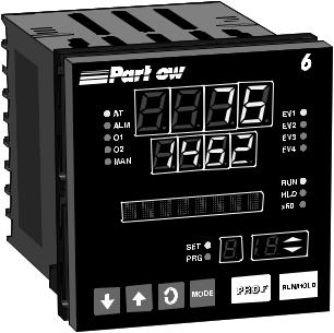
This instrument is a powerful, easy-to-use 1/4 DIN setpoint programmer with full PID control capability (complete with Self-Tune and Pre-Tune facilities).
Its standard features include:
•Up to eight programs of up to 16 free-format (e.i. dwell, ramp, join, or end) segments each.
•Facility to join programs to one another in any sequence (maximum program length 121 segments)
•User can change currently-running program segment.
•Delayed Start of Program facility
•End of Program relay output
•Universal input-thermocouple, RTD (PT100) or DC linear -
user-selectable.
•Universal power supply (90 -264V AC 50/60 Hz)
•Configurable from front panel
•Comprehensive front panel displays
•Front panel sealing to NEMA 4 standard
•Behind-panel depth only 100mm (3.94 inches)
•Power Failure Recovery Optional features include:
•Remote control and selection of program (plug-in option)
•Up to four Event relay outputs (plug-in option)
•Second control output
•Recorder output (setpoint or process variable)
•RS-485 serial communications
•User-definable program tag names
•Support software (Off-line Configurator, On-line Graphic Program Editor) - operates via RS-485 communications link.
•Real Time Clock
Edition 1 |
1 |
MIC 1462 Manual |
The Setpoint Programmer has numerous operating modes:
Base Mode: Day to day PID control operations with no program running. In this mode, a program may be selected to run.
Profile Run Mode: A selected program is running, held or waiting for a pre-defined delay before starting. In this mode, the operator can view status and program information.
Profile Define Mode: Used to view/create/edit programs. this mode is entered either from Base Mode (selected program may be edited/created) or from Program Run Mode (currently-running program may be edited).
Controller Define Mode: Used to define the controller characteristics.
Tune: Used to adjust tuning parameters
Alarm: Used to define and set alarms
Enable: Provides a means of enabling or disabling access to setpoint changes and each of the non-control modes.
FIGURE 1-1
Front Panel

 2
2
MIC 1462 Manual |
2 |
Edition 1 |

Section 2 - Installation & Wiring
2.1UNPACKING PROCEDURE
1.Remove the instrument from its packing. The instrument is supplied with a panel gasket and push-fit strap. Retain the packing for future use, should it be necessary to transport the instrument to a different site or return it to the factory for repair/testing.
2.Examine the delivered items for damage or deficiencies. If any is found, notify the carrier immediately. Check that the model number shown on the label affixed to the instrument housing corresponds to that ordered (see Appendix D).
2.2PANEL-MOUNTING THE SETPOINT PROGRAMMER
The panel on which the instrument is to be mounted must be rigid and may be up to 6.0 mm (.25 inches ) thick. The cutout required for a single instrument is shown in Figure 2-1.
FIGURE 2-1
Cut-Out Dimensions
92 mm +0.5 - 0.00 (3.62”+.020 - .000)
PANEL |
|
|
|
|
|
|
|
|
|
|
|
|
|
|
|
92 mm + 0.5 - 0.0 |
||||
CUTOUT |
|
|
(3.62” + .020 - .000) |
|||
SIZE |
|
|
|
|
|
|
|
|
|
|
|
|
|
|
|
|
|
|
|
|
|
|
|
|
|
|
|
Edition 1 |
3 |
MIC 1462 Manual |

The main dimensions of the instrument are shown below.
FIGURE 2-2
Main Dimensions
 100 mm (3.94 in.)
96 mm
(3.78 in)
Side View
 10 mm (0.39 in.)
96 mm
(3.78 in.)
Max. Panel Thickness 6.0mm (.25 inches)
To panel-mount the instrument:
1. Insert the rear of the instrument housing through the cutout (from the front of the mounting panel) and hold the instrument lightly in position against the panel. Ensure that the panel gasket is not distorted and that the instrument is positioned squarely against the mounting panel. Apply pressure to the front panel bezel only.
Caution: Do not remove the panel gasket, as this may result in inadequate clamping of the instrument in the panel.
2. Slide the fixing strap in place (Figure 2-3) and push it forward until it is firmly in contact with the rear face of the mounting panel (the tongues on the strap should have engaged in matching rachet positions on the instrument housing and the fixing strap springs should be pushing firmly against the mounting panel rear face).
MIC 1462 Manual |
4 |
Edition 1 |
Once the instrument is installed in its mounting panel, it may be subsequently removed from its housing, if necessary, as described in Appendix B.
FIGURE 2-3
Panel-Mounting the Instrument
Mounting Clamp
Controller Housing
Tongues on mounting clamp engage in ratchet slots on controller housing
2.3 PREPARATION FOR WIRING
Electrical noise is a phenomenon typical of industrial environments. The following are guidelines that must be followed to minimize the effect of noise upon any instrumentation.
2.3.1 INSTALLATION CONSIDERATIONS
Listed below are some of the common sources of electrical noise in the industrial environment:
•Ignition Transformers
•Arc Welders
•Mechanical contact relay(s)
•Solenoids
Edition 1 |
5 |
MIC 1462 Manual |
Before using any instrument near the device listed, the instructions below should be followed:
1.If the instrument is to be mounted in the same panel as any of the listed devices, separate them by the largest distance possible. For maximum electrical noise reduction, the noise generating devices should be mounted in a separate enclosure.
2.If possible, eliminate mechanical contact relay(s) and replace with solid state relays. If a mechanical relay being powered by an instrument output device cannot be replaced, a solid state relay can be used to isolate the instrument.
3.A separate isolation transformer to feed only instrumentation should be considered. The transformer can isolate the instrument from noise found on the AC power input.
4.If the instrument is being installed on existing equipment, the wiring in the area should be checked to insure that good wiring practices have been followed.
2.3.2AC POWER WIRING
Neutral (For 115 VAC)
It is good practice to assure that the AC neutral is at or near ground potential. To verify this, a voltmeter check between neutral and ground should be done. On the AC range, the reading should not be more than 50 millivolts. If it is greater than this amount, the secondary of this AC transformer supplying the instrument should be checked by an electrician. A proper neutral will help ensure maximum performance from the instrument.
2.3.3WIRE ISOLATION
Four voltage levels of input and output wiring may be used with the unit:
•Analog input or output (i.e. thermocouple, RTD, VDC, mVDC, or mADC)
•SPDT Relays
•SSR driver outputs
•AC power
MIC 1462 Manual |
6 |
Edition 1 |
The only wires that should run together are those of the same category. If they need to be run parallel with any of the other lines, maintain a minimum 6 inch space between wires. If wires must cross each other, do so at 90 degrees. This will minimize the contact with each other and reduces "cross talk". "Cross Talk" is due to the EMF (Electro Magnetic Flux) emitted by a wire as current passes through it. This EMF can be picked up by other wires running in the same bundle or conduit.
In applications where a High Voltage Transformer is used (i.e. ignition systems) the secondary of the transformer should be isolated from all other cables.
This instrument has been designed to operate in noisy environments, however, in some cases even with proper wiring it may be necessary to suppress the noise at the source.
2.3.4 USE OF SHIELDED CABLE
Shielded cable helps eliminate electrical noise being induced on the wires. All analog signals should be run with shielded cable. Connection lead length should be kept as short as possible, keeping the wires protected by the shielding. The shield should be grounded at one end only. The preferred grounding location is the sensor, transmitter, or transducer.
2.3.5 NOISE SUPPRESSION AT THE SOURCE
Usually when good wiring practices are followed no further noise protection is necessary. Sometimes in severe electrical environments, the amount of noise is so great that it has to be suppressed at the source. Many manufacturers of relays, contactors, etc. supply "surge suppressors" which mount on the noise source.
For those devices that do not have surge suppressors supplied. RC (resis- tance-capacitance) networks and/or MOV (metal oxide varistors) may be added.
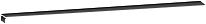
Inductive Coils - MOV's are recommended for transient suppression in inductive coils connected in parallel and as close as possible to the coil. See Figure 2-4. Additional protection may be provided by adding an RC network across the MOV.
Edition 1 |
7 |
MIC 1462 Manual |
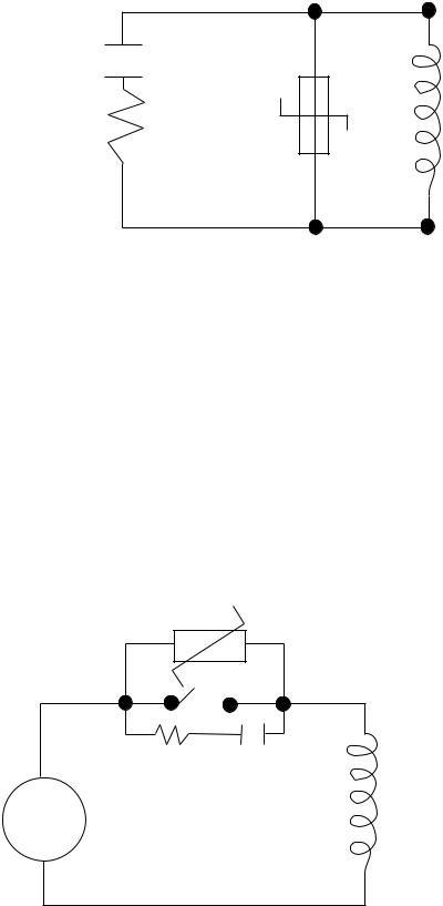
FIGURE 2-4
0.5 mfd 1000V
Inductive 115V 1/4W 220 Coil 230V 1W ohms
Contacts - Arcing may occur across contacts when the contact opens and closes. This results in electrical noise as well as damage to the contacts. Connecting a RC network properly sized can eliminate this arc.
For circuits up to 3 amps, a combination of a 47 ohm resistor and 0.1 microfarad capacitor (1000 volts) is recommended. For circuits from 3 to 5 amps, connect 2 of these in parallel. See Figure 2-5, below.
FIGURE 2-5
MOV
AC
R C
Inductive
Coil
MIC 1462 Manual |
8 |
Edition 1 |
2.3.5 SENSOR PLACEMENT (THERMOCOUPLE OR RTD)
Two wire RTD's should be used only with lead lengths less than 10 feet.
If the temperature probe is to be subjected to corrosive or abrasive conditions, it should be protected by the appropriate thermowell. The probe should be positioned to reflect true process temperature:
In liquid media - the most agitated area
In air - the best circulated area
Edition 1 |
9 |
MIC 1462 Manual |
 Loading...