


Form 2844
Edition 11
© August 1993
Updated March 1997
MIC 2000
Installation, Wiring, Operation Manual
Brand

PAGE 2
NOTE
Information in this installation, wiring, and operation manual is subject to change without notice. One manual is provided with each instrument at the time of
shipment. Extra copies are available at the price published on the front cover.
Copyright © August 1993, all rights reserved. No part of this publication may be reproduced, transmitted, transcribed or stored in aretrieval system, or translated into any language in any form by any means without the written permission of the factory.
This is the Eleventh Edition of the 1/4 DIN Controller manual. It was written and produced entirely on a desk- top-publishing system. Disk versions are available by written request to the factory - Advertising and Publications Department.
We are glad you decided to open this manual. It is written so that you can take full advantage of the features of your new process controller.
It is strongly recommended that factory equipped applications incorporate a high or low limit protective device which will shut down the equipment at a preset process condition in order to preclude possible damage to property or products.

PAGE 3
Table |
of |
Contents |
|
|||
SECTION |
1 |
- |
GENERAL |
Page Number |
||
1.1 |
Product Description |
5 |
||||
SECTION |
2 |
- |
|
|
|
|
INSTALLATION |
& |
WIRING |
|
|||
2.1 |
Installation and Wiring |
7 |
||||
2.2 |
Preparation for Wiring |
8 |
||||
2.3 |
Input Connections |
13 |
||||
2.4 |
Output Connections |
19 |
||||
SECTION |
3 |
- |
|
|
|
|
CONFIGURATION |
& OPERATION |
|
||||
3.1 |
Configuration and Operation |
22 |
||||
3.2 |
Operation Summary |
22 |
||||
3.3 |
Configuration Summary |
24 |
||||
3.4 |
Tune Mode Operation |
34 |
||||
SECTION 4 - CONTROL CAPABILITY |
|
|||||
4.1 |
Control Capability |
37 |
||||
4.2 |
Control Responses |
37 |
||||
4.3 |
Direct/Reverse Operation of Control Outputs |
37 |
||||
4.4 |
On-Off Control/Latched On-Off |
38 |
||||
4.5 |
Time Proportioning Control |
38 |
||||
4.6 |
Current Proportioning Control |
38 |
||||
4.7 |
Position Proportioning Control |
38 |
||||
4.8 |
Dual Output Control |
40 |
||||
4.9 |
Manual Operation of Proportional Outputs |
41 |
||||
4.10 |
Automatic Transfer Function |
41 |
||||
4.11 |
Setpoint Adjustments |
42 |
||||
SECTION |
5 |
- |
SERVICE |
|
||
5.1 |
Service |
|
|
|
44 |
|
5.2 |
Calibration |
|
|
44 |
||
5.3 |
Test Mode |
|
|
48 |
||
5.4 |
Troubleshooting and diagnostics |
52 |
||||
APPENDICES |
|
|
|
|||
A - Board Layout - Jumper Positioning |
|
|||||
|
|
|
|
Figure A-1 Power Supply Board |
59 |
|
|
|
|
|
Figure A-2 Processor Board |
60 |
|
|
|
|
|
Figure A-3 Option Board |
61, 62 |
|
B - Glossary of terms |
|
63 |
||||
C - Model Number Hardware Matrix Details |
66 |
|||||
D - Specifications |
|
67 |
||||
E - Software Record/Reference Sheet |
70 |
|||||
Warranty |
|
|
|
|
Inside back cover |
|

PAGE 4
FIGURES |
& TABLES |
|
|
Figure 1-1 |
Controller Display Illustration |
5 |
|
Figure 2-1 |
Panel Opening Sizes and Installation |
7 |
|
Figure 2-2 |
Noise Suppression |
9 |
|
Figure 2-3 |
Noise Suppression |
10 |
|
Figure 2-4 |
Wiring Label |
13 |
|
Figure 2-5 |
AC Power |
13 |
|
Figure 2-6 |
Thermocouple Input |
14 |
|
Figure 2-7 |
RTD Input |
14 |
|
Figure 2-8 |
Volt, mV, mADC Input |
15 |
|
Figure 2-9A |
24VDC Transmitter Power Supply |
16 |
|
Figure 2-9B |
24VDC Power Supply |
16 |
|
Figure 2-10 |
Remote Setpoint Input |
17 |
|
Figure 2-11 |
Remote Digital Communications |
18 |
|
Figure 2-12 |
Relay Output |
19 |
|
Figure 2-13 |
SSR Driver Output |
20 |
|
Figure 2-14 |
mADC Output |
21 |
|
Figure 2-15 |
Position Proportioning Output |
21 |
|
Figure 4-1 |
Proportional Bandwidth effect on Output |
39 |
|
Figure 4-2 |
Dual Proportional Outputs |
40 |
|
Figure 4-3 |
Setpoint Ramp Rate Example |
42 |
|
Figure 4-4 |
Re-transmission Example |
43 |
|
Figure 4-5 |
Setpoint Re-transmission Example |
43 |
|
Table 3-1 |
Enable Mode Configuration Procedures |
24 |
|
Table 3-2 |
Program Mode Configuration Procedures |
28 |
|
Table 3-3 |
Tune Mode Configuration Procedures |
33 |
|
Table |
5-1 |
Calibration Procedures |
45 |
Table |
5-2 |
Test Procedures and Description |
49 |
FLOW CHARTS
Flow - Calibration |
44 |
Flow - Enable Mode |
25 |
Flow - Program Mode |
26 |
Flow - Setpoint |
42 |
Flow - Standby Mode |
41 |
Flow - Test Mode |
48 |
Flow - Tune Mode |
32 |
PAGE 5
Product Description 1.1
1.1.1 GENERAL
This instrument is a microprocessor based single loop controller capable of measuring, displaying and controlling temperature, pressure, flow, and level from a variety of inputs.
Control functions, alarm settings and other parameters are easily entered through the front keypad. All user's data can be protected from unauthorized changes with it’s ENABLE MODE security system. Battery back-up protects against data loss during AC power outages.
The input is user configurable to directly connect to either thermocouple, RTD, mVDC, VDC or mADC inputs. Thermocouple and RTD linearization, as well as thermocouple cold junction compensation is performed automatically. The sensor input is isolated . The instrument can operate on either 115VAC or 230VAC power at 50/60Hz. It is housed in an extruded aluminum enclosure suitable for panel mounting. It may be surface mounted using an optional adaptor.
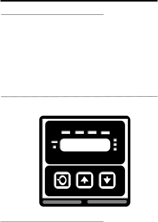
FIGURE 1-1
MAN |
OUT1 |
OUT2 ALRM |
S.P. |
|
°C |
|
|
°F |
|
|
U |
1.1.2 DISPLAYS
Each instrument is provided with a digital display and status indicators as shown in Figure 1-1. The digital display is programmable to show the process variable only, process variable and setpoint, deviation from setpoint only, deviation and setpoint, or setpoint continuously. Status indication is as shown (Figure 1-1). Display resolution is programmable for 0 to 3 decimal places depending upon the input type selected.

PAGE 6
1.1.3 CONTROL
The instrument can be programmed for on-off, time proportioning, current proportioning, or position proportioning control implementations depending on the model number. A second control output is an available option. Proportional control implementations are provided with fully programmable separate PID parameters.
1.1.4 ALARM
Alarm indication is standard on all instruments. Alarm type may be set as PROCESS DIRECT or REVERSE (High or Low), DEVIATION DIRECT or REVERSE (Above or Below setpoint), or DEVIATION BAND TYPE (Closed or Open within the band). Alarm status is indicated by LED. An alarm output can be provided by assigning any output(s) SPST relay(s) or SSR Driver(s) to the alarm.
1.1.5 EXTENDED |
FEATURES |
SOFTWARE |
EA Software Features |
|
|
Fast Scan |
|
Provides an optional faster scan rate of 3 scans per second. |
|
|
Normal scan is one scan per second. |
Process Rounding |
Provides rounding of the process value displayed to reduce display |
|
|
|
fluctuation. For example, the displayed value can be rounded to |
|
|
the nearest 5 (display -5, 0, 5, 10, etc.). This is for display only and |
|
|
does not affect the control action. |
Extended Current |
The current outputs available can be extended to include 0-20mA |
|
Output Ranges |
|
and 0-5VDC (with the appropriate shunt resistor), rather than the |
|
|
standard 4-20mA and 1-5VDC outputs. |
Process/Setpoint |
|
The process or setpoint value can be scaled over any desired |
Value Retransmit |
|
range and retransmitted using one of the current outputs. (This |
Capability |
|
precludes the use of the output for control). |
Percent Output |
|
Provides a relay actuation based upon a proportional output being |
Relay Actuation |
|
above or below a specified value. |
Contact Closure Sensing |
This feature provides the following action: When a contact closure |
|
for SP=PV |
|
is sensed, the setpoint will be set equal to the current process |
|
|
value. This is only done on the transition from open to closed, and |
|
|
not continuously while the switch is closed. |
EB Software Features |
|
|
Setpoint Ramp |
Provides a limitation on how fast the process value will ramp to setpoint by |
|
Rate |
limiting the rate of change of an internal setpoint used for control versus |
|
|
the setpoint the operator specifies. |
|

PAGE 7
Installation and Wiring 2.1
Prior to proceeding with installation, verify the AC power input required by the instrument. AC power input is either 115 VAC or 230 VAC and is specified in the model number and on the wiring label affixed to the instrument housing. See Figure 2-4 (page 13) for a wiring label description.
230 VAC models may be converted to 115 VAC operation by the user, by changing the position of jumpers soldered on the Power Supply Board, see Appendix A-1 (page 59) for details.
Electrical code requirements and safety standards should be observed and installation performed by qualified personnel.
The electronic components of the instrument may be removed from the housing during installation. To remove the components, loosen the locking screw located in the lower center of the instrument’s front panel. Pull the entire instrument straight out of the
housing. During re-installation, the vertically mounted circuit boards should be properly aligned in the housing. Be sure that the instrument is installed in the original housing. This can be verified by matching the serial number on the unit to the serial number on the housing. (Serial numbers are located on the inside of the housing enclosure and on the label on the underside of the front panel). This will insure that each instrument is accurate to its published specifications. The ambient compensator on the rear of the housing enclosure is calibrated to the electronics of the instrument at the factory.
Recommended panel opening sizes are illustrated below (Figure 2-1). After the opening is properly cut, insert the instrument housing into the panel opening. Insert the two panhead screws provided, through the holes in the mounting bracket into the holes in the rear of the instrument as shown in Figure 2-1. Firmly tighten the screws. Instruments are shipped standard for panel mounting. To surface mount, an adaptor is required and should be specified when ordering. For installation in wash-down areas, a watertight cover is available.
FIGURE 2-1 PANEL OPENING SIZES AND INSTALLATION
4.8 (.188) MAX PANEL THICKNESS
165.9 (6.53)
146.8 (5.78)
96.0 |
|
90.4 |
(3.78) |
|
|
|
(3.560) |
|
|
|
Side View
96.0 (3.78) |
|
Mounting Bracket |
|
|
|
Panel |
|
92 + or - |
0.8 |
|
|
|
|
||
(3.622 + or - .031) |
|
|
|
PANEL |
|
92+ or-.8 |
|
CUTOUT |
(3.622 |
|
|
+ or-.031) |
|
||
SIZE |
|
90.4 |
|
|
|
||
|
|
|
(3.560) |
Top View
All dimensions shown |
|
in mm and inches. Inches |
|
shown in ( ). |
Mounting screw |
|

PAGE 8
Preparation for Wiring 2.2
2.2.1 WIRING GUIDELINES
Electrical noise is a phenomenon typical of industrial environments. The following are guidelines that must be followed to minimize the effect of noise upon any instrumentation.
2.2.1.1 INSTALLATION CONSIDERATIONS
Listed below are some of the common sources of electrical noise in the industrial environment:
•Ignition Transformers
•Arc Welders
•Mechanical contact relay(s)
* Solenoids
Before using any instrument near the devices listed, the instructions below should be followed:
1.If the instrument is to be mounted in the same panel as any of the listed devices, separate them by the largest distance possible. For maximum electrical noise reduction, the noise generating devices should be mounted in a separate enclosure.
2.If possible, eliminate mechanical contact relay(s) and replace with solid state relays. If a mechanical relay being powered by an instrument output device cannot be replaced, a solid state relay can be used to isolate the instrument.
3.A separate isolation transformer to feed only instrumentation should be considered. The transformer can isolate the instrument from noise found on the AC power input.
4.If the instrument is being installed on existing equipment, the wiring in the area should be checked to insure that good wiring practices have been followed.
2.2.1.2 AC POWER WIRING
Earth Ground
The instrument includes noise suppression components that require an earth ground connection to function. To verify that a good earth ground is being attached, make a resistance check from the instrument chassis to the nearest metal water pipe or proven earth ground. This reading should not exceed 100 ohms. Use a 12 gauge (or heavier) insulated stranded wire.
Neutral (For 115VAC)
It is good practice to assure that the AC neutral is at or near ground potential. To verify this, a voltmeter check between neutral and ground should be done. On the AC range, the reading should not be more than 50 millivolts. If it is greater than this amount, the secondary of this AC transformer supplying the instrument should be checked by an electrician. A proper neutral will help ensure maximum performance from the instrument.
2.2.1.3 WIRE ISOLATION
Four voltage levels of input and output wiring may be used with the unit:
•Analog input or output (i.e. thermocouple, RTD, VDC, mVDC or mADC)
•SPST Relays
•SSR driver outputs
•AC power
The only wires that should be run together are those of the same category. If they need to be run parallel with any of the other lines, maintain a minimum 6 inch space between the wires. If wires must cross each other, do so at 90 degrees. This will minimize the contact with each other and reduces "cross talk" "Cross talk" is due to the EMF (electro Magnetic Flux) emitted by a wire as current passes through it. This EMF can be picked up by other wires running in the same bundle or conduit.
PAGE 9
In applications where a High Voltage Transformer is used, (i.e. ignition systems) the secondary of the transformer should be isolated from all other cables.
This instrument has been designed to operate in noisy environments, however, in some cases even with proper wiring it may be necessary to suppress the noise at its source.
2.2.1.4 USE OF SHIELDED CABLE
Shielded cable helps eliminate electrical noise being induced on the wires. All analog signals should be run with shielded cable. Connection lead length should be kept as short as possible, keeping the wires protected by the shielding. The shield should be grounded at one end only. The preferred grounding location is the sensor, transmitter or transducer.
2.2.1.5 NOISE SUPPRESSION AT THE SOURCE
Usually when good wiring practices are followed no further noise protection is necessary. Sometimes in severe electrical environments, the amount of noise is so great that it has to be suppressed at the source. Many manufacturers of relays, contactors, etc. supply "surge suppressors" which mount on the noise source.
For those devices that do not have surge suppressors supplied, RC (resistance-capacitance) networks and/or MOV (metal oxide varistors) may be added.
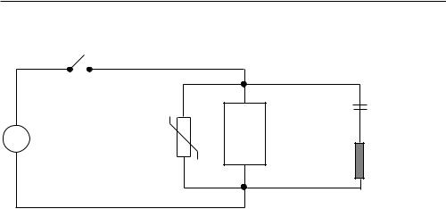
Inductive Coils - MOV's are recommended for transient suppression in inductive coils connected in parallel and as close a possible to the coil. See Figure 2-2. Additional protection may be provided by adding an RC network across the MOV.
FIGURE 2-2
|
|
|
0.5 |
|
|
|
mfd |
A.C. |
MOV |
Inductive |
1000V |
Load |
|
||
|
|
220 ohms
115V 1/4W
230V 1W
(Continued on next page)
PAGE 10
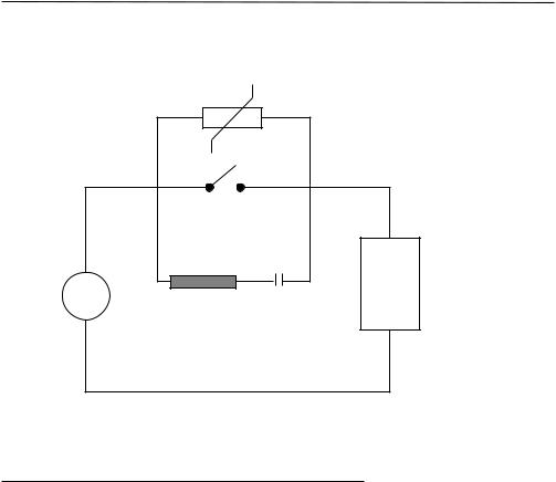
Contacts - Arcing may occur across contacts when the contact opens and closes. This results in electrical noise as well as damage to the contacts. Connecting a RC network properly sized can eliminate this arc.
For circuits up to 3 amps, a combination of a 47 ohm resistor and 0.1 microfarad capacitor (1000 volts) is recommended. For circuits from 3 to 5 amps, connect 2 of these in parallel. See Figure 2-3.
FIGURE 2-3
MOV
A.C. |
|
|
Inductive |
R |
C |
Load |
2.2.2 SENSOR PLACEMENT (Thermocouple or RTD)
Two wire RTD's should be used only with lead lengths less than 10 feet.
If the temperature probe is to be subjected to corrosive or abrasive conditions, it should be protected by the appropriate thermowell. The probe should be positioned to reflect true process temperature:
In liquid media - the most agitated area.
In air - the best circulated area
PAGE 11
THERMOCOUPLE LEAD RESISTANCE
Thermocouple lead length can affect instrument since the size (gauge) and the length of the wire affect lead resistance.
To determine the temperature error resulting from the lead length resistance, use the following equation:
Terr = TLe * L |
where; |
TLe = value from appropriate table below |
|
|
||||||
|
|
|
|
L = length of leadwire in thousands of feet. |
|
|
||||
TABLE 1 |
|
|
|
|
|
|
|
|
|
|
|
|
|
|
|
|
|||||
Temperature error in °C per 1000 feet of Leadwire |
|
|
|
|
||||||
AWG |
|
Thermocouple Type: |
|
|
|
|
|
|
||
No. |
|
J |
K |
T |
R |
S |
E |
B |
N |
C |
10 |
|
.34 |
.85 |
.38 |
1.02 |
1.06 |
.58 |
7.00 |
1.47 |
1.26 |
12 |
|
.54 |
1.34 |
.61 |
1.65 |
1.65 |
.91 |
11.00 |
2.34 |
2.03 |
14 |
|
.87 |
2.15 |
.97 |
2.67 |
2.65 |
1.46 |
17.50 |
3.72 |
3.19 |
16 |
|
1.37 |
3.38 |
1.54 |
4.15 |
4.18 |
2.30 |
27.75 |
5.91 |
5.05 |
18 |
|
2.22 |
5.50 |
2.50 |
6.76 |
6.82 |
3.73 |
44.25 |
9.40 |
8.13 |
20 |
|
3.57 |
8.62 |
3.92 |
10.80 |
10.88 |
5.89 |
70.50 |
14.94 |
12.91 |
24 |
|
8.78 |
21.91 |
9.91 |
27.16 |
27.29 |
14.83 |
178.25 |
37.80 |
32.64 |
|
|
|
|
|
|
|
|
|
|
|
TABLE 2 |
|
|
|
|
|
|
|
|
|
|
|
|
|
|
|
|
|||||
Temperature Error in °F per 1000 feet of Leadwire |
|
|
|
|
||||||
AWG |
|
Thermocouple Type: |
|
|
|
|
|
|
||
No. |
|
J |
K |
T |
R |
S |
E |
B |
N |
C |
10 |
|
.61 |
1.54 |
.69 |
1.84 |
1.91 |
1.04 |
12.60 |
2.65 |
2.27 |
12 |
|
.97 |
2.41 |
1.09 |
2.97 |
2.96 |
1.64 |
19.80 |
4.21 |
3.66 |
14 |
|
1.57 |
3.86 |
1.75 |
4.81 |
4.76 |
2.63 |
31.50 |
6.69 |
5.74 |
16 |
|
2.47 |
6.09 |
2.77 |
7.47 |
7.52 |
4.14 |
49.95 |
10.64 |
9.10 |
18 |
|
4.00 |
9.90 |
4.50 |
12.17 |
12.28 |
6.72 |
79.95 |
10.64 |
9.10 |
20 |
|
6.43 |
15.51 |
7.06 |
19.43 |
19.59 |
10.61 |
126.90 |
26.89 |
23.24 |
24 |
|
15.80 |
39.44 |
17.83 |
48.89 |
49.13 |
26.70 |
320.85 |
68.03 |
58.75 |
|
|
|
|
|
|
|
|
|
|
|
Example:
A 1/4 Din unit is to be located in a control room 660 feet away from the process. Using 16
AWG, type J thermocouple, how much error is induced?
Terr = TLe * L
TLe = 2.47 (°F/1000 ft) from Table 2
Terr = 2.47 (°F/1000 ft) * 660 ft
Terr = 1.6 °F
PAGE 12
RTD LEAD RESISTANCE
RTD lead length can affect instrument accuracy, since the size (gauge) and length of the wire affect lead resistance.
To determine the temperature error resulting from the lead length resistance, use the following equation:
Terr = TLe * L |
where; |
TLe = value from Table 3 if 3 wire RTD or Table 4 is 2 wire RTD |
||
|
|
|
L = length of lead wire in thousands of feet |
|
TABLE 3 |
3 Wire RTD |
|||
|
|
|
|
|
AWG No. |
|
Error °C |
Error °F |
|
10 |
|
± 0.04 |
± 0.07 |
|
12 |
|
± 0.07 |
± 0.11 |
|
14 |
|
± 0.10 |
± 0.18 |
|
16 |
|
± 0.16 |
± 0.29 |
|
18 |
|
± 0.26 |
± 0.46 |
|
20 |
|
± 0.41 |
± 0.73 |
|
24 |
|
± 0.65 |
± 1.17 |
|
|
|
|
|
|
TABLE 4 |
2 Wire RTD |
|||
|
|
|
|
|
AWG No. |
|
Error °C |
Error °F |
|
10 |
|
± 5.32 |
± 9.31 |
|
12 |
|
± 9.31 |
± 14.6 |
|
14 |
|
± 13.3 |
± 23.9 |
|
16 |
|
± 21.3 |
± 38.6 |
|
18 |
|
± 34.6 |
± 61.2 |
|
20 |
|
± 54.5 |
± 97.1 |
|
24 |
|
± 86.5 |
± 155.6 |
|
Example:
An application uses 2000 feet of 18 AWG copper lead wire for a 3 wire RTD sensor. What is the worst case error due to this leadwire length?
Terr = TLe * L
TLe = ± .46 (°F/1000 ft) from Table 3
Terr = ± .46 (°F/1000 ft) * 2000 ft
Terr = ± 0.92°F
PAGE 13
FIGURE 2-4 WIRING LABEL
|
|
|
|
|
|
|
|
|
|
|
|
|
H |
|
SERIAL A |
POS.PROP. |
8 |
REMOTE |
|
||
|
|
|
WIPER |
|
SETPT |
+ |
|
|||
|
|
|
|
|
|
|||||
|
RELAY C |
|
|
|
|
|
|
|
|
|
|
|
G |
|
SERIAL B |
POS.PROP. |
7 |
OUT2 |
+ |
|
|
|
|
|
HIGH |
|
4-20mA |
|
|
|||
|
|
|
|
|
|
|
|
|
||
|
|
|
|
|
|
|
|
|
|
|
|
|
F |
|
|
|
|
6 |
OUT1 |
+ |
|
|
|
|
|
|
|
|
||||
|
|
|
|
|
|
4-20mA |
|
|||
|
RELAY B |
|
|
|
|
|
|
|
|
|
|
|
E |
|
|
|
|
5 |
RETURN |
|
|
|
|
|
|
|
|
|
|
|
||
|
|
|
INPUT RATINGS: |
|
|
|
|
|
|
|
|
|
|
|
|
|
|
|
|
||
|
|
D |
115/230 VAC 50/60 HZ 15VA MAX |
|
4 |
|
|
|
||
|
|
|
|
|
|
|
|
|
||
|
RELAY A |
RELAY OUTPUT RATINGS: |
|
|
|
|
|
|||
|
115VAC 5.0A RESISTIVE |
|
|
|
|
|
||||
|
|
|
|
|
|
|
|
|||
|
|
C |
230VAC 2.5A RESISTIVE |
|
3 |
SIGNAL + |
|
|||
|
|
230VAC 1/8 HP |
|
|
|
|||||
|
|
|
115/230VAC 250VA |
|
|
|
|
|
|
|
|
|
|
MAXIMUM AMBIENT : 55°C |
|
|
|
|
|
||
|
|
B |
|
2 |
CJC |
|
|
|||
|
|
|
|
|
|
|
|
|||
|
|
115 |
|
|
|
|
|
|
|
|
|
|
VAC |
|
|
|
|
|
|
|
|
|
|
230 |
|
|
|
|
1 |
SIGNAL - |
|
|
|
|
A |
|
|
|
|
|
|||
|
|
|
|
|
|
|
|
|
|
|
|
|
|
|
GROUND |
MADE IN U.S.A. |
|
|
|||
|
|
|
|
|
|
|
|
|
|
|
|
|
|
|
|
|
|
|
|
|
|
Input Connections 2.3
In general, all wiring connections are made to the instrument after it is installed. Avoid electrical shock. AC power wiring must not be connected to the source distribution panel until all wiring connection procedures are completed.
2.3.1 INPUT CONNECTIONS
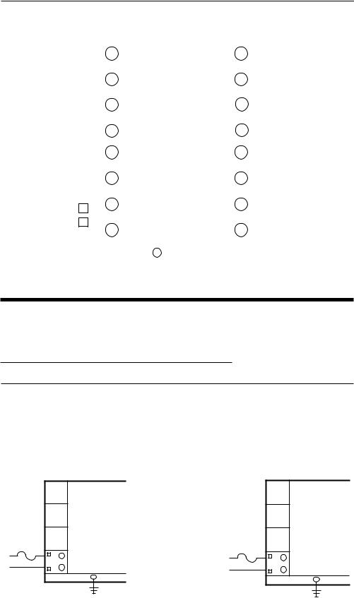
FIGURE 2-5
AC Power
Connect 115 VAC hot and neutral to terminals B and A respectively as illustrated below.
Connect 230 VAC as described below. Connect Earth ground to the ground screw as shown.
115 VAC INSTRUMENT VOLTAGE |
230 VAC INSTRUMENT VOLTAGE |
Rear View |
Rear View |
.5 AMP* FUSE
L1
L2
B
A
GROUND
.25 AMP* FUSE
L1
L2
B
A
GROUND
*Supplied by customer |
*Supplied by the customer |
PAGE 14
FIGURE 2-6
Thermocouple (T/C) Input
Make thermocouple connections as illustrated below. Connect the positive leg of the thermocouple to terminal 3, and the negative to terminal 1. For industrial environments with comparatively high electrical noise levels, shielded thermocouples and extension wire are recommended. Be sure that the input conditioning jumpers are properly positioned for a thermocouple input. See Appendix A-2 (page 60) and A-3 (page 61, 62).
THERMOCOUPLE INPUT
Rear view
8
7
6
5
4
3
2
1
FIGURE 2-7
+
-
300 OHMS MAXIMUM LEAD
RTD Input
Make RTD connections as illustrated below. For a three wire RTD, connect the resistive leg of the RTD to terminal 3, and the common legs to terminal 1 and 5. For a two wire RTD, connect one wire to terminal 1 and the other wire to terminal 3 as shown below. A jumper wire supplied by the customer must be installed between terminals 1 and 5. Be sure that the input conditioning jumpers are properly positioned for an RTD input. See Appendix A-2 (page 60) and A-3 (page 61, 62).
2 WIRE RTD INPUT |
3 WIRE RTD INPUT |
Rear View |
Rear View |
|
|
||
8 |
8 |
|
7 |
7 |
|
6 |
6 |
|
5 |
5 |
|
JUMPER* |
||
|
||
4 |
4 |
|
|
||
3 |
3 |
|
|
||
2 |
2 |
|
|
||
1 |
1 |
|
100 OHM* |
||
100 OHM* |
||
PLATINUM |
||
|
PLATINUM |
*Supplied by the customer
*Supplied by customer
PAGE 15
FIGURE 2-8
Volt, mV, mADC Input
Make volt, millivolt and milliamp connections as shown below. Terminal 3 is positive and terminal 1 is negative. Milliamp input requires a 250 ohm shunt resistor (supplied with the instrument) installed across the input terminals and by configuring the instrument for either 0 to 5 or 1 to 5 VDC input. If desired, milliamp DC input can be facilitated by installing an optional 2.5 ohm resistor across the input terminals and configuring the instrument for either 0 to 50 or 10 to 50 mVDC. Be sure that the input conditioning jumpers are properly positioned for the input type selected. See Appendix A-2 (page 60) and A-3 (page 61, 62).
MILLIAMP DC INPUT |
MILLIAMP DC INPUT |
Rear View
8
7
6
5
4
3
2
1
Rear View
|
8 |
|
7 |
|
6 |
Shielded Twisted |
5 |
|
|
Pair |
4 |
+ |
3 |
|
2 |
- |
1 |
|
MILLIAMP DC SOURCE
250 OHM SHUNT RESISTER REQUIRED
Shielded Twisted
+ Pair
-
MILLIAMP DC SOURCE
2.5 OHM SHUNT RESISTER REQUIRED
NOTE: Fault detection is not functional for 0-20mA inputs.
MILLIVOLT DC INPUT |
VOLT DC INPUT |
Rear View
8
7
6
5
4
3
2
1
Rear View
|
|
8 |
|
|
|
7 |
|
|
|
6 |
|
|
|
5 |
|
+ |
Shielded Twisted |
4 |
|
Pair |
|||
|
|||
|
3 |
||
|
|
||
|
|
2 |
1
-
Shielded Twisted
+Pair
-
MILLIVOLT DC |
VOLT DC |
SOURCE |
SOURCE |
50 MILLIVOLT DC |
5 VOLT DC |
MAXIMUM |
MAXIMUM |
NOTE: Fault detection is not functional for 0-20mA inputs.
PAGE 16
FIGURE 2-9A
24 Volt Transmitter Power Supply (XP Option)
Make connections as shown below. Terminal 3 is positive (+) and terminal 1 is negative (-)/ Be sure the input conditioning jumpers are properly positioned for the input type selected. See Figure A-2 Processor Board, page 60, and Figure A-3 Option Board, page 61 or 62. Note the 250 ohm shunt resistor is not required.
+3 |
+ |
|
2 |
Two Wire |
|
Transmitter |
||
|
-1 
 -
-
FIGURE 2-9B
24 Volt Power Supply (XA Option)
Make connections as shown below. Terminal G is positive (+) and terminal H is negative (-). Be sure the input conditioning jumpers are properly positioned. See Figure A-2 Processor Board, page 60 and Figure A-3 Option Board, page 61 or 62.
H -
24VDC
G +
PAGE 17
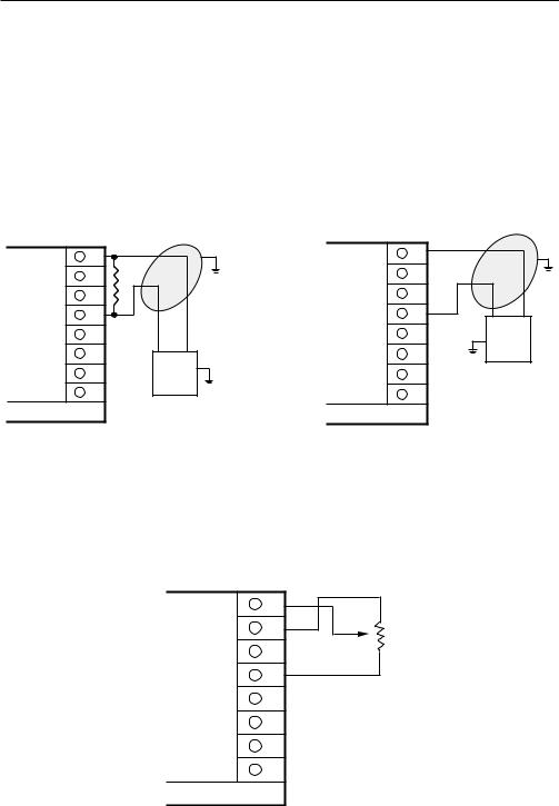
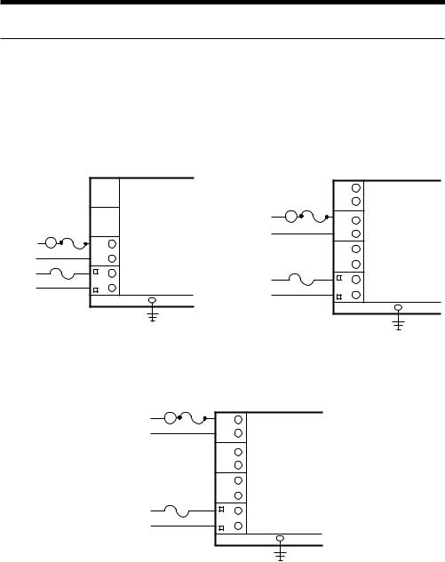
FIGURE 2-10
Remote Setpoint Input - VDC, mADC and Potentiometer
Input connections are illustrated below. Terminal 8 is positive and terminal 5 is negative. The remote setpoint input can be configured for either 0 to 5VDC or 1 to 5 VDC input. Make sure that the voltage input matches the voltage configuration selected in the Program mode. For mA inputs, a 250 ohm shunt resistor must be installed between terminals 5 and 8. For remote setpoint using a potentiometer, JU1 on options board must be in MM/PP (see page 61, 62).
CURRENT DC REMOTE SETPOINT |
VOLT DC REMOTE SETPOINT |
||||
|
|
|
|
|
Shielded Twisted |
Rear View |
+ |
Shielded Twisted Pair |
Rear View |
+ |
Pair |
|
|
||||
|
|
8 |
|
||
8 |
|
|
|
||
|
|
|
|
|
|
7 |
|
|
7 |
|
|
6 |
- |
|
6 |
- |
|
5 |
|
5 |
|
||
4 |
|
|
4 |
|
|
3 |
|
|
3 |
|
|
2 |
|
|
2 |
|
VOLT DC |
|
|
|
|
|
SETPOINT |
1 |
|
MILLIAMP |
1 |
|
SIGNAL |
|
|
|
|
5VDC |
|
|
|
SETPOINT |
|
|
MAXIMUM |
|
|
SIGNAL |
|
|
|
|
|
250 OHM |
|
|
|
|
|
SHUNT |
|
|
|
|
|
RESISTER |
|
|
|
|
|
NEEDED |
|
|
|
POTENTIOMETER
Rear View
8 |
|
|
7 |
|
|
6 |
|
|
5 |
|
|
4 |
150 ohm to |
|
10 K ohm |
||
|
||
3 |
|
|
2 |
|
|
1 |
|
PAGE 18
FIGURE 2-11
Remote Digital Communications RS 485 Terminals 7 & 8
If the communications network continues on to other units, connect the shields together, but not to the instrument. A terminating resistor should be installed at the terminals of the last instrument in the loop. The shield should be grounded at the computer or the
convertor box, if used. See the Protocol Manual (Form 2878) for more details on the use of the digital communications option.
DIGITAL COMMUNICATIONS
CONNECTIONS - TERMINALS 7 & 8
|
FROM HOST |
Output 2 cannot be DC Current |
COMPUTER |
8 |
|
7 |
|
6 |
|
5 |
TO OTHER |
4 |
INSTRUMENTS |
|
|
3 |
|
2 |
|
1 |
|
PAGE 19
Output Connections 2.4
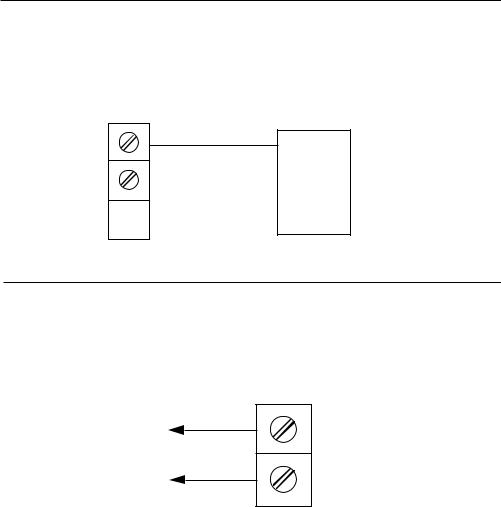
FIGURE 2-12
Relay Output
Connections are made to relay A as illustrated below. Connect relay(s) B & C (if present) in the same manner. Relay contacts are rated at 5 amp Resistive load 115 VAC.
RELAY A |
RELAY B |
LOAD
L2
L1
INPUT
POWER
Rear View
|
LOAD |
|
L2 |
|
L1 |
D |
|
C |
|
B |
INPUT |
|
POWER |
A |
|
|
GROUND |
|
|
RELAY C |
|
LOAD |
Rear View |
|
|
|
L2 |
|
H |
L1 |
|
G |
F
E
D
C
INPUT
B
POWER
A
Rear View
H
G
F
E
D
C
B
A
GROUND
GROUND

PAGE 20
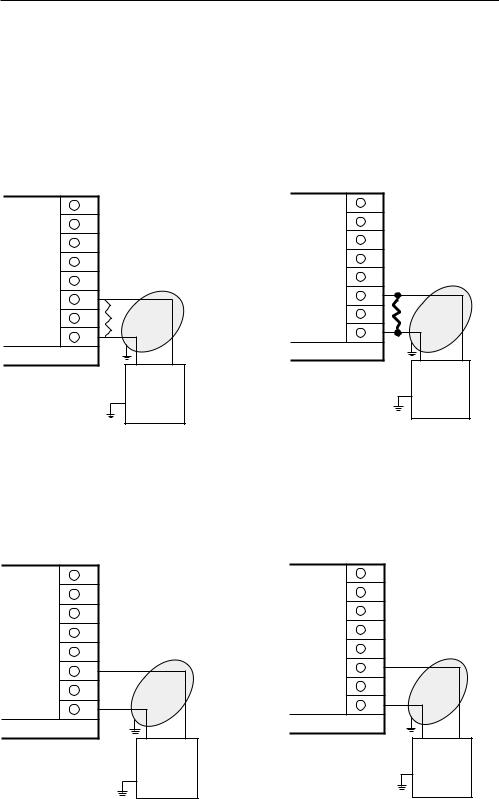
FIGURE 2-13
SSR Driver Output
Connections are made to the solid state relay driver output located in the Relay A position as shown. The solid state relay driver is a 5 VDC current sink output type. Connect the solid state relay driver(s) in the Relay B and C position (if present) in the same manner.
SSR DRIVER (RELAY A) |
SSR DRIVER (RELAY B) |
|
SOLID STATE
RELAY +
-
INPUT
POWER
|
Rear View |
Rear View |
|
H |
|
H |
|
|
|
||
G |
SOLID STATE |
G |
|
|
RELAY + |
||
F |
F |
||
|
- |
||
E |
E |
||
D |
|
D |
|
|
|
||
C |
|
C |
|
|
|
||
B |
INPUT |
B |
|
POWER |
|||
|
|||
|
|
||
A |
|
A |
|
|
|
||
|
GROUND |
GROUND |
|
|
|
SSR DRIVER (RELAY C)
SOLID STATE |
Rear View |
|
RELAY + |
H |
|
- |
||
G |
||
|
F |
|
|
E |
|
|
D |
|
INPUT |
C |
|
|
||
POWER |
B |
A
GROUND
PAGE 21
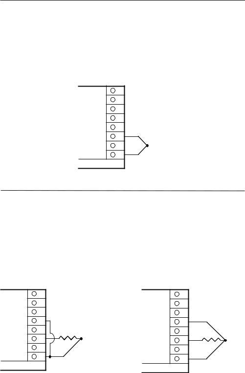
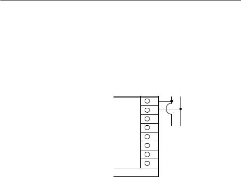
FIGURE 2-14 mADC Output
Connections are made for current outputs 1 or 2 as shown below. Connect the positive lead to terminal 6 for Output 1 or terminal 7 for Output 2 , the negative leads connect to terminal 5. Current outputs will operate up to 650 ohms maximum load. The current output(s) are
4 - 20 mADC. With the EA option, they can be selected for either 4-20 or 0-20 mADC.
DC CURRENT OUTPUT 1 |
DC CURRENT OUTPUT 2 |
|
Rear View
8
7
6
5
4
3
2
1
+
-
Rear View
Shielded |
|
8 |
|
|
|
Twisted |
|
7 |
Pair |
|
|
|
|
|
|
|
6 |
|
|
5 |
|
LOAD |
4 |
|
650 OHMS |
|
|
|
|
|
MAXIMUM |
3 |
|
|
|
|
|
2 |
|
|
1 |
+
-
Shielded
Twisted
Pair
LOAD
650 OHMS MAXIMUM
FIGURE 2-15
Position Proportioning Output
The relay and slidewire feedback connections are made as illustrated below. The relay assigned to Output 1 will be used to drive the motor in the open direction and the relay assigned to Output 2 will be used to drive the motor in the closed direction. The minimum slidewire feedback resistance is 135 ohms, the maximum resistance is 10K ohms.
L2
OPEN
CLOSE
Modulating Motor
|
|
8 |
POS.PROP. |
|
|
WIPER |
|
|
|
|
POS.PROP. |
|
|
7 |
HIGH + |
|
F |
Rear View |
|
|
RELAY B |
|
|
|
E |
5 |
RETURN |
|
|
||
|
D |
|
|
|
RELAY A |
|
|
L1 |
C |
|
|
PAGE 22
Configuration and Operation 3.1
3.1.1 POWER UP PROCEDURE
Verify all electrical connections have been properly made before applying power to the instrument.
If the instrument is being configured (set up) for the first time, it may be desirable to disconnect the controller output connections. The instrument will go into the Control mode following the power up sequence and the output(s) may turn on. During power up, the seven digit model number will be displayed. Next, the software revision level will be displayed, followed by the EPROM tab number. Instrument self test 1 through 3 will take place as they are displayed. After completion of the tests Ctrl will be displayed for 3 seconds. At this time another mode of operation may be selected by pressing the SCROLL key.
3.1.2 CONFIGURATION PROCEDURE
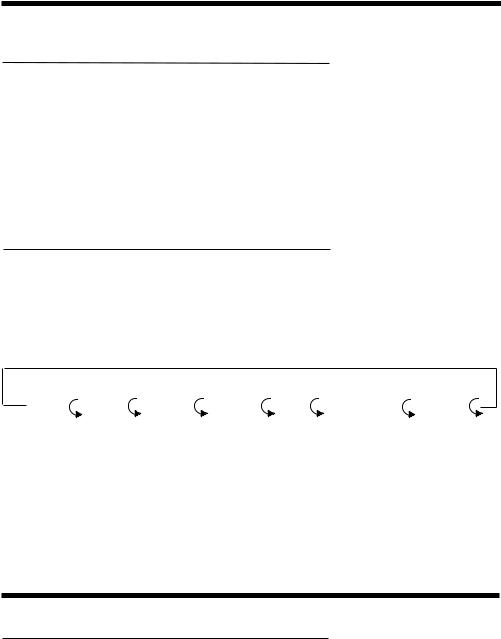
Parameter selections and data entry are made via the front keypad. To ease configuration and operation, the user selectable features have been divided into several sections (modes). Data and parameter entries are made by stepping through each mode and making an appropriate response or entry to each step as necessary for the application.
Control |
Test |
Calibrate |
Program |
Tune |
Setpoint Select |
Standby |
(CtrL) |
(tESt) |
(CAL) |
(Prog) |
(tunE) |
(SPS) |
(StbY) |
Operation Summary 3.2
3.2.1 KEYPAD OPERATION
SCROLL KEY
This key is used to:
1.Display enabled modes of operation
2.Display a mode parameter value
3.Advance display from a parameter value to the next parameter code
4.Exit some calibration/test functions
5.Used with other keys:
A.With UP key to view output percentages of proportional output(s)
B.With DOWN key
1.On power up to alter model number
2.Enter calibration /test functions
 Loading...