


Form 2882 • Price $21.00
Edition 6 • © Dec. 1996
Revised February, 1998
ONE AND TWO PEN CIRCLE CHART RECORDER
MRC 7000
Installation, Wiring, Operation Manual
Brand

nformation in this installation, wiring, and operation Imanual is subject to change without notice. One
manual is provided with each instrument at the time of shipment. Extra copies are available at the price published on the front cover.
Copyright © December 1996, all rights reserved. No part of this publication may be reproduced, transmitted, transcribed or stored in a retrieval system, or translated into any language in any form by any means without the written permission of the Partlow-West Company.
This is the Sixth Edition of the MRC 7000 Recorder Manual. It was written and produced entirely on a desk-top-publish- ing system. Disk versions are available by written request to the Partlow-West Advertising and Publications Department.
We are glad you decided to open this manual. It is written so that you can take full advantage of the features of your new MRC 7000 microbased chart recorder.
Is is strongly recommended that factory equipped applications NOTE incorporate a high or low limit protective device which will shut
down the equipment at a preset process condition in order to preclude possible damage to property or products.
2

TABLE OF CONTENTS
SECTION 1 - GENERAL |
PAGE NUMBER |
|
1.1 |
Product Description |
5 |
SECTION 2 - INSTALLATION & WIRING |
|
|
2.1 |
Installation & Wiring |
7 |
2.2 |
Unpacking |
7 |
2.3 |
Location |
7 |
2.4 |
Mounting |
7 |
2.5 |
Preparation for Wiring |
8 |
2.6 |
Wiring Connections |
13 |
SECTION 3 - CONFIGURATION |
|
|
3.1 |
Configuration (Set Up) |
18 |
3.2 |
Configuration/Jumper Positioning |
19 |
3.3 |
Operation Summary |
19 |
3.4 |
Start up Procedure |
20 |
3.5 |
Front Panel Operation |
21 |
SECTION 4 - SERVICE |
|
|
4.1 |
Service |
33 |
4.2 |
Changing Charts |
33 |
4.3 |
Changing Pens |
33 |
4.4 |
Calibration |
34 |
4.5 |
Test Mode |
39 |
4.6 |
Troubleshooting and Diagnostics |
43 |
APPENDICES |
|
|
A - Board Layouts |
|
|
|
A-1 Processor Board |
50 |
|
A-2 SPST Relay/SSR Driver Output Board |
51 |
|
A-3 SPDT Relay/SSR Driver Output Board |
52 |
|
A-4 Current Output Board |
53 |
B - Glossary |
54 |
|
C - Model Number Hardware Matrix Details |
55 |
|
D - Specifications |
56 |
|
E - Software Record/Reference Sheet |
59 |
|
Warranty |
Inside back page |
|
3

FIGURES & TABLES
Figure 1-1 |
Recorder Description |
5 |
Figure 1-2 |
Recorder Display |
6 |
Figure 2-1 |
Installation Panel Dimensions Conduit Opening Locations |
8 |
Figure 2-2 |
Noise Suppression |
10 |
Figure 2-3 |
Noise Suppression |
10 |
Figure 2-4 |
Board and Terminal Locations |
13 |
Figure 2-5 |
AC Power Input |
14 |
Figure 2-6 |
Thermocouple Inputs |
14 |
Figure 2-7 |
RTD Inputs |
14 |
Figure 2-8 |
Milliamp, Volt and Millivolt Inputs |
15 |
Figure 2-9 |
Digital Communications |
15 |
Figure 2-10A |
SPST Relay Output |
16 |
Figure 2-10B |
SPDT Relay Output |
16 |
Figure 2-11 |
SSR Output |
16 |
Figure 2-12 |
Current Output |
17 |
Figure 2-13 |
24 VDC Power Supply Option |
17 |
Figure 3-1 |
Keypad Features |
19 |
Figure 4-1 |
Changing Pens |
33 |
Table 3-1 |
Enable Mode Configuration Procedure |
24 |
Table 3-2 |
Program Mode Configuration Procedure |
28 |
Table 3-3 |
Alarm Set Mode Configuration Procedure |
32 |
Table 4-1 |
Calibration Procedure |
35 |
Table 4-2 |
Test Procedures and Description |
40 |
FLOW CHARTS
Flow - Alarm Set |
32 |
Flow - Calibration |
34 |
Flow - Enable |
24 |
Flow - Program |
25 |
Flow - Test |
39 |
4

Product Description |
1.1 |
1.1.1 GENERAL
The instrument is a microprocessor based circular chart recorder capable of measuring, displaying and recording from a variety of inputs. Applications include temperature, pressure, flow and others. The instrument can be specified as either a single or dual pen unit.
Recording, alarm, or limit settings and other parameters are easily entered via the keypad. All user data can be protected from unauthorized changes by the Enable mode security system, and is protected against memory loss, as a result of AC power outage, by battery back-up.
The process variable input for each terminal is user configurable to directly connect to either thermocouple, RTD, mVDC, VDC, or mADC inputs. Changes in input type can easily be made by the user. Thermocouple and RTD linearization, as well as thermocouple cold junction compensation, is performed automatically. The instrument process variable inputs are isolated. An isolated 24 VDC regulated transmitter power supply can be provided in the instrument for use with up to two 4 to 20 mADC sensor transducers.
The instrument can be ordered to operate on either 115 VAC or 230 VAC power at 50/60 Hz. The 230 VAC option includes a switch for selecting either 230 VAC or 115 VAC operation. The recorder is housed in a structural foam enclosure suitable for panel or surface mounting.
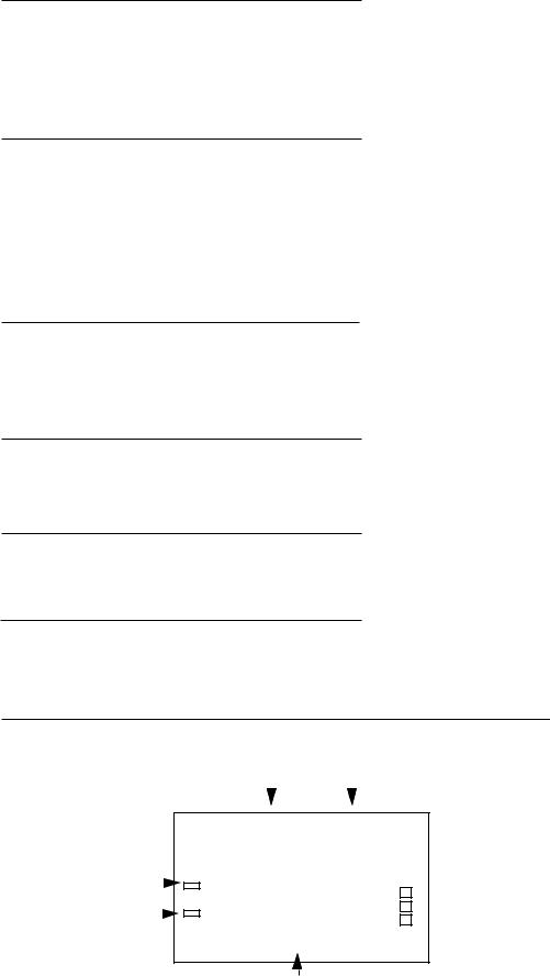
FIGURE 1-1
Pen 1 Display
Pen 1 Reset Key
Scroll Key
 Up Key


 Down Key
Pen 2 Reset Key
Pen 2 Display
5
1.1.2 RECORDING
The instrument records the selected process variable on a 10-inch circular chart. One box of standard charts is provided with each recorder. Charts are available in a wide selection of ranges. Chart rotation speed is programmable from 0.1 to 999.9 hours per revolution in 0.1 hour increments. The instrument can be ordered with one or two pens. Pen 1 is red and Pen 2 is green. Pens are the disposable fiber-tip type.
1.1.3 DISPLAYS
Each instrument is provided with a digital display and status indicator for each pen provided, (See Figure 1-1, page 5). The digital display is configured to display the Process Value. The display in the upper right corner is for Pen 1, the display in the lower right corner is for Pen 2 (if provided). The display includes status indicators for Alarm 1 and Alarm 2, degrees C, degrees F, engineering units, and setpoint (for limits). See Figure 1-2 (below).
Display resolution is programmable for 0.1 or 1 degree for thermocouple and RTD inputs, and zero, one, two or three decimal places for other input types.
1.1.4 ALARM
Two alarm indications are standard for each pen on all instruments. Alarm settings are programmable. Alarm type may be set as process direct or reverse (high or low). Alarm outputs can be provided by assigning any relay(s) Single Pole/Single Throw (SPST or Solid State Relay (SSR) driver) to the respective alarm.
1.1.5 LIMIT
Limit indication is standard on limit devices. Limit settings are programmable. Limits may be High or Low and can be provided by assigning any relay to the respective limit.
1.1.6 PROCESS VALUE RE-TRANSMISSION OUTPUT
If an instrument is specified with mADC current output(s), any of the outputs may be programmed to operate as a process value re-transmission output. The output is scaleable.
1.1.7 DIGITAL COMMUNICATIONS
The instrument can be ordered with a Digital Communications option that provides the capability of bi-directional communications with a supervisory computer.
FIGURE 1-2
|
Alarm 1 |
Alarm 2 |
|||||||
|
|
|
|
|
|
|
|
|
|
|
|
|
|
|
|
|
|
|
|
|
|
|
|
|
|
|
|
|
|
|
|
|
|
|
|
|
|
|
|
|
|
|
|
|
|
|
|
|
|
|
|
|
|
|
|
|
ALRM1 |
ALRM2 |
|||
Limit |
|
|
|
|
|||||||
Setpoint |
|
|
|
|
|
|
|
|
|
|
C |
|
|
|
|
|
|||||||
|
|
|
|
|
|
|
|
|
|||
|
|
|
|
||||||||
|
|
|
|
|
|
|
|
|
|
|
|
Minus Sign |
|
|
|
|
|
|
|
|
|
F |
|
|
|
|
|
|
|
|
|
|
|||
|
|
|
|
|
|
|
|
|
|||
|
|
|
|
|
|
|
|
U |
|||
|
|
|
|
||||||||
|
|
|
|
|
|
|
|||||
|
|
|
|
|
|||||||
|
|
|
|
|
|
|
|
|
|
|
|
|
|
|
|
|
|
|
|
|
|
|
|
Digital Display
6

Installation and Wiring 2.1
Read these instructions carefully before proceeding with installation and operation. Electrical code requirements and safety standards should be observed. Installation should be performed by qualified personnel.
CAUTION: The Instrument AC power input is specified in the model number and on the wiring label affixed to the the top center of the platen. Verify the AC power input required by the instrument prior to proceeding with
installation.
Unpacking 2.2
Remove the instrument from the carton and inspect for any damage due to shipment. If any damage is noticed due to transit, report and file a claim with the carrier. Write the model number and serial number of the instrument on the inside of the front cover of this Operation Manual for future reference.
Location 2.3
Locate the instrument away from excessive moisture, oil, dust, and vibration. Do not subject the instrument to operating temperatures outside of the 32° to 131°F (0° to 55° C) range.
Mounting 2.4
Figure 2-1 (page 8) shows an installation view and physical dimensions for a panel mounted instrument. The panel where the instrument will be mounted must provide rigid support for the approximately 20 pound instrument. Adjacent instruments may be mounted within a minimum of 2 inches horizontally and 3 inches vertically, providing that proper panel support is supplied.
PANEL MOUNTING HARDWARE REQUIRED: (not provided with instrument)
(4) 1/4"-20 x 2" flat head bolts w/nuts
(4) appropriate lock washers
PANEL MOUNTING:
1)Cut panel opening to the dimensions illustrated in Figure 2-1 (page 8).
2)Insert the instrument in the panel opening. Firmly fasten the instrument to the panel using
the nuts, bolts and lock washers.
SURFACE MOUNTING:
1) Install the mounting brackets, ordered separately, on the vertical sides of instrument housing. Use the brackets to fasten the instrument to the surface.
7

FIGURE 2-1
EC1
16
mm)
|
|
|
|
|
|
|
|
|
|
|
|
|
|
|
|
2 1 |
|
(64 mm) |
|
||||
|
|
|
|
|
|
|
|
|
|
|
|
|
|
|
|||||||||
|
|
|
|
|
|
|
|
|
|
|
15 |
1 |
2 |
|
|
|
|
|
|
||||
|
|
|
|
|
|
|
|
|
|
|
(384.2 mm) |
|
|
|
|
|
|
|
|
|
|||
|
|
|
|
|
|
|
|
|
|
|
|
|
|
|
|
|
|
|
|
||||
|
|
|
|
|
|
|
|
|
|
8 |
|
|
|
|
|
4 |
|
|
|
||||
|
|
|
|
|
|
|
|
|
|
|
WIDTH OF COVER |
16 |
|
|
|||||||||
|
|
|
|
|
|
|
|
|
|
|
|
|
|
|
|
|
|
9 1 |
|||||
|
|
|
|
|
|
|
|
2 |
19 |
(65.9 mm) |
|||||||||||||
|
|
|
|
|
|
|
|
|
|
|
|
|
|
||||||||||
|
|
|
|
|
|
|
|
|
32 |
|
|
|
9 |
|
|
|
|
|
|
|
|
|
|
|
|
|
|
|
|
|
|
|
|
|
|
|
|
|
|
|
|
|
|
|
|
||
|
|
|
|
|
|
|
|
|
|
|
|
|
|
|
|
|
|
|
|
|
|
||
|
|
|
|
|
|
|
|
|
|
|
|
|
|
32 DIA.(7.1mm) |
|
|
|
|
|
|
|||
|
|
|
|
|
|
|
|
|
|
|
|
|
|
|
|
|
|
|
|
|
|
|
|
12 |
5 |
7 |
1 |
|
|
|
|
|
|
|
|
|
|
|
|
|
|
|
|
|
|||
|
|
8 |
|
2 |
|
|
|
|
|
|
|
|
|
|
|
|
|
|
|
|
|
||
(320.7 mm) |
|
|
|
|
|
|
|
|
|
|
|
|
|
|
|
|
|
||||||
|
|
|
|
(190.5 |
mm) |
|
|
|
|
|
|
|
|
|
|
|
|
|
|
||||
|
|
|
|
|
|
|
|
|
|
|
|
|
|
|
|
|
|
||||||
|
|
|
|
|
|
|
|
|
|
|
|
|
|
|
|
|
|
|
|
|
|
|
|
|
|
|
|
|
|
|
|
|
|
|
|
|
|
|
|
|
|
|
|
|
|
|
|
|
|
|
|
|
|
|
|
|
|
|
|
|
|
|
|
|
|
|
|
|
|
|
|
|
|
|
|
1 |
(342.5 mm) |
|
|
|
|
|
|
|
|
|
|
|
|||
|
|
|
|
13 2 |
|
|
|
||
|
|
|
|
|
|
|
|
|
|
|
|
|
13 |
15 ( 354 mm) |
|
|
|
|
|
|
|
|
|
|
|
|
|||
|
|
|
|
16 |
|
|
|
|
|
Panel cut-out for flush mounting
2.5"
63.5mm
Preparation for Wiring 2.5
2.5.1 WIRING GUIDELINES
Electrical noise is a phenomenon typical of industrial environments. The following are guidelines that must be followed to minimize the effect of noise upon any instrumentation.
2.5.1.1 INSTALLATION CONSIDERATIONS
Listed below are some of the common sources of electrical noise in the industrial environment:
•Ignition Transformers
•Arc Welders
•Mechanical contact relay(s)
•Solenoids
Before using any instrument near the devices listed, the instructions below should be followed:
1.If the instrument is to be mounted in the same panel as any of the listed devices, separate them by the largest distance possible. For maximum electrical noise reduction, the noise generating devices should be mounted in a separate enclosure.
8
2.If possible, eliminate mechanical contact relay(s) and replace with solid state relays. If a mechanical relay being powered by an instrument output device cannot be replaced, a solid state relay can be used to isolate the instrument.
3.A separate isolation transformer to feed only instrumentation should be considered. The transformer can isolate the instrument from noise found on the AC power input.
4.If the instrument is being installed on existing equipment, the wiring in the area should be checked to insure that good wiring practices have been followed.
2.5.1.2 AC POWER WIRING
Earth Ground
The instrument includes noise suppression components that require an earth ground connection to function. To verify that a good earth ground is being attached, make a resistance check from the instrument chassis to the nearest metal water pipe or proven earth ground. This reading should not exceed 100 ohms. Each instrument should have a dedicated earth ground. Do not chain link multiple instrument ground wires.
Neutral (For 115VAC)
It is good practice to assure that the AC neutral is at or near ground potential. To verify this, a voltmeter check between neutral and ground should be done. On the AC range, the reading should not be more than 50 millivolts. If it is greater than this amount, the secondary of this AC transformer supplying the instrument should be checked by an electrician. A proper neutral will help ensure maximum performance from the instrument.
2.5.1.3 WIRE ISOLATION/SEGREGATION
The instrument is designed to promote proper separation of the wiring groups that connect to the instrument. The AC power wire terminals are located near the top of the instrument boards. The analog signal terminals are located near the bottom of the instrument boards. Maintain this separation of the wires to insure the best protection from electrical noise. If the wires need to be run parallel with any other wiring type(s), maintain a minimum 6 inch space between the wires. If wires must cross each other, do so at 90 degrees to minimize the contact with each other and reduce cross talk. Cross talk is due to the Electro Magnetic Field emitted by a wire as current passes through it.
2.5.1.4 USE OF SHIELDED CABLE
Shielded cable helps eliminate electrical noise being induced on the wires. All analog signals should be run with shielded cable. Connection lead length should be kept as short as possible, keeping the wires protected by the shielding. The shield should be grounded at one end only. The preferred grounding location is at the sensor, transmitter or transducer.
2.5.1.5 NOISE SUPPRESSION AT THE SOURCE
Usually, when good wiring practices are followed, no further noise protection is necessary. Sometimes in severe electrical environments, the amount of noise is so great that it has to be suppressed at the source. Many manufacturers of relays, contactors, etc. supply "surge suppressors" which mount on the noise source.
For those devices that do not have surge suppressors supplied, RC (resistance-capacitance) networks and/or MOV (metal oxide varistors) may be added.
Inductive Coils - MOV's are recommended for transient suppression in inductive coils connected in parallel and as close as possible to the coil. See Figure 2-2, page 10. Additional protection may be provided by adding an RC network across the MOV.
Contacts - Arcing may occur across contacts when the contact opens and closes. This results in electrical noise as well as damage to the contacts. Connecting a RC network properly sized can eliminate this arc.
For circuits up to 3 amps, a combination of a 47 ohm resistor and 0.1 microfarad capcitor (1000 volts) is recommended. For circuits from 3 to 5 amps, connect 2 of these in parallel. See Figure 2-3, page 10.
9
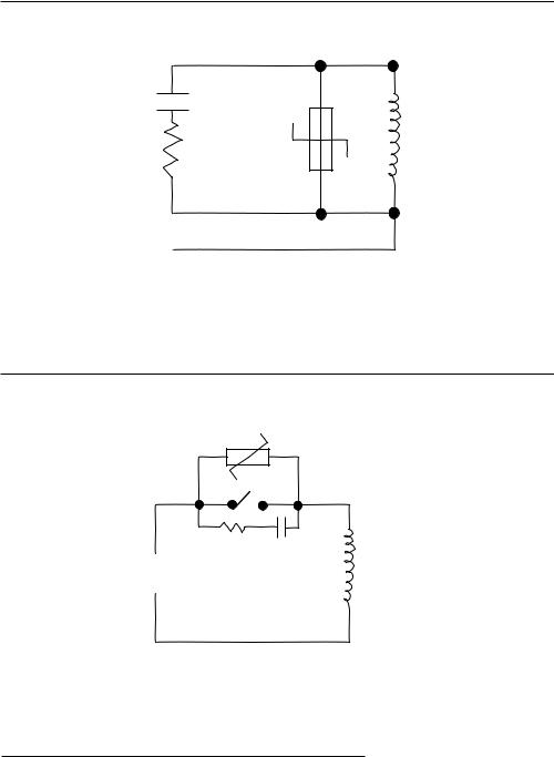
FIGURE 2-2
0.5 mfd
1000V
Coil
220 ohms
115V 1/4W
230V 1W
FIGURE 2-3
MOV
R C
Inductive
Load
2.5.2 SENSOR PLACEMENT (THERMOCOUPLE OR RTD)
Thermocouple lead resistance should not exceed 300 ohms. It this is exceeded, instrument accuracy could be affected.
Two wire RTD's should be used only with lead lengths less than 10 feet.
If the temperature probe is to be subjected to corrosive or abrasive conditions, it should be protected by the appropriate thermowell. The probe should be positioned to reflect true process temperature:
In liquid media - the most agitated area.
In air - the best circulated area.
10
THERMOCOUPLE LEAD RESISTANCE
Thermcouple lead length can affect instrument accuracy since the size (gauge) and the length of the wire affect lead resistance.
To determine the temperature error resulting from the lead length resistance, use the following equation:
Terr = TLe * L |
where; TLe = value from appropriate table below |
|
L = length of leadwire in thousands of feet |
TABLE 1
Temperature error in °C per 1000 feet of Leadwire
AWG |
Thermocouple Type: |
|
|
|
|
|
|
||
No. |
J |
K |
T |
R |
S |
E |
B |
N |
C |
10 |
.68 |
1.71 |
.76 |
2.05 |
2.12 |
1.15 |
14.00 |
2.94 |
2.53 |
12 |
1.08 |
2.68 |
1.21 |
3.30 |
3.29 |
1.82 |
22.00 |
4.68 |
4.07 |
14 |
1.74 |
4.29 |
1.95 |
5.34 |
5.29 |
2.92 |
35.00 |
7.44 |
6.37 |
16 |
2.74 |
6.76 |
3.08 |
8.30 |
8.35 |
4.60 |
55.50 |
11.82 |
10.11 |
18 |
4.44 |
11.00 |
5.00 |
13.52 |
13.65 |
7.47 |
88.50 |
18.80 |
16.26 |
20 |
7.14 |
17.24 |
7.84 |
21.59 |
21.76 |
11.78 |
141.00 |
29.88 |
25.82 |
24 |
17.56 |
43.82 |
19.82 |
54.32 |
54.59 |
29.67 |
356.50 |
75.59 |
65.27 |
|
|
|
|
|
|
|
|
|
|
TABLE 2
Temperature Error in °F per 1000 feet of Leadwire
AWG |
Thermcouple Type: |
|
|
|
|
|
|
||
No. |
J |
K |
T |
R |
S |
E |
B |
N |
C |
10 |
1.22 |
3.07 |
1.37 |
3.68 |
3.81 |
2.07 |
25.20 |
5.30 |
4.55 |
12 |
1.94 |
4.82 |
2.18 |
5.93 |
5.93 |
3.27 |
39.60 |
8.42 |
7.32 |
14 |
3.13 |
7.73 |
3.51 |
9.61 |
9.53 |
5.25 |
63.00 |
13.38 |
11.47 |
16 |
4.93 |
12.18 |
5.54 |
14.93 |
15.04 |
8.28 |
99.90 |
21.28 |
18.20 |
18 |
7.99 |
19.80 |
9.00 |
24.34 |
24.56 |
13.44 |
159.30 |
33.85 |
29.27 |
20 |
12.85 |
31.02 |
14.12 |
38.86 |
39.18 |
21.21 |
253.80 |
53.79 |
46.48 |
24 |
31.61 |
78.88 |
35.67 |
97.77 |
98.26 |
53.40 |
641.70 |
136.07 |
117.49 |
|
|
|
|
|
|
|
|
|
|
Example:
An MRC is to be located in a control room 660 feet away from the process. Using 16 AWG, type J thermocouple, how much error is induced?
Terr = Tle * L
TLe = 4.93 (°F/1000 ft) from Table 2
Terr = 4.93 (°F/1000 ft) * 660 ft
Terr = 3.3 °F
11
RTD LEAD RESISTANCE
RTD lead length can affect instrument accuracy, since the size (gauge) and length of the wire affect lead resistance.
To determine the temperature error resulting from the lead length resistance, use the following equation:
Terr = TLe * L |
where; |
TLe = value from Table 3 if 3 wire RTD or Table 4 if 2 wire RTD |
|||
|
|
|
|
L = length of lead wire in thousands of feet |
|
TABLE 3 |
3 Wire RTD |
||||
|
|
|
|
|
|
AWG No. |
|
Error ° C |
Error °F |
|
|
10 |
|
|
+/-0.04 |
+/-0.07 |
|
12 |
|
|
+/-0.07 |
+/-0.11 |
|
14 |
|
|
+/-0.10 |
+/-0.18 |
|
16 |
|
|
+/-0.16 |
+/-0.29 |
|
18 |
|
|
+/-0.26 |
+/-0.46 |
|
20 |
|
|
+/-0.41 |
+/-0.73 |
|
24 |
|
|
+/-0.65 |
+/-1.17 |
|
|
|
|
|
|
|
TABLE 4 |
2 Wire RTD |
||||
|
|
|
|
|
|
AWG No. |
|
Error °C |
Error °F |
|
|
10 |
|
|
+/-5.32 |
+/-9.31 |
|
12 |
|
|
+/-9.31 |
+/-14.6 |
|
14 |
|
|
+/-13.3 |
+/-23.9 |
|
16 |
|
|
+/-21.3 |
+/-38.6 |
|
18 |
|
|
+/-34.6 |
+/-61.2 |
|
20 |
|
|
+/-54.5 |
+/-97.1 |
|
24 |
|
|
+/-86.5 |
+/-155.6 |
|
|
|
|
|
|
|
Example:
An application uses 2000 feet of 18 AWG copper lead wire for a 3 wire RTD sensor. What is the worst case error due to this leadwire length?
Terr = TLe * L
TLe = +/-.46 (°F/1000 ft) from Table 3
Terr = +/-.46 (‡F/1000 ft) * 2000 ft
Terr = +/-0.92°F
12

Wiring Connections |
2.6 |
All wiring connections are typically made to the instrument at the time of installation. Connections should be made at the terminal blocks , two 12 gauge wires maximum. Terminal blocks are designated TB1 through TB13. See Figure 2-4 for the terminal block locations (SPST Relay Board shown).
FIGURE 2-4
1 2 |
1 2 3 4 |
|
|
1 2 3 4 |
|
|
1 2 3 |
||||||||||||
|
|
|
|
|
|
|
|
|
|
|
|
|
|
|
|
|
|
|
|
|
TB1 |
|
|
TB6 |
|
TB7 |
|
|
|
TB8 |
|||||||||
|
|
|
|
|
|
RELAY/SSR Driver |
|
|
|
|
|||||||||
|
|
|
|
|
|
Board |
|
|
|
|
|
|
|
|
|
|
|||
Processor Board |
|
|
|
|
|
|
|
|
|
|
|
|
|
|
TB9 |
||||
|
|
|
|
|
|
|
|
|
|
|
|
|
|
|
|
|
|
|
|
1 2 3 4
|
|
|
|
|
|
|
|
|
|
|
|
|
|
|
|
|
|
|
|
|
Current Output Board |
|
|
|
|||||||
TB 2 |
|
|
|
|
|
|
|
|
|
|
|
|
|
|
|
|
|
|
|
|
|
|
|
|
|
||||||
|
|
|
|
|
|
|
|
|
|
|
|
|
|
|
|
|
|
|
|
|
|
|
|
|
|
|
|
|
|
||
1 |
2 |
|
|
|
|
|
|
|
|
|
TB5 |
|
|
TB10 |
TB11 |
TB12 |
TB13 |
||||||||||||||
|
TB3 |
|
TB4 |
|
|
|
|
||||||||||||||||||||||||
|
|
|
|
|
|
|
|
|
|
|
|
|
|
|
|
|
|
|
|
|
|
|
|
|
|
|
|
|
|
|
|
|
|
|
|
|
|
|
|
|
|
|
|
|
|
|
|
|
|
|
|
|
|
|
|
|
|
|
|
|
|
|
|
|
|
1 2 |
|
1 2 3 4 5 |
|
1 2 3 4 5 |
1 |
2 |
1 |
2 |
|
1 |
2 |
|
1 |
|
|
||||||||||||||
2.6.1 ELECTRICAL CONDUIT OPENINGS
The instrument case will have 3 or 4 conduit openings, depending upon the number of outputs specified. To help mimumize electrical noise that may adversely affect the operation of the instrument the wires indicated below should be routed through the conduit opening specified. See Figure 2-1 (page 8) for conduit opening locations.
EC1AC Power Input
EC2Analog input and mADC outputs
EC3SPST, SPDT relay or SSR driver outputs
EC4SPST, SPDT relay or SSR driver outputs (provided when > 4 relays & SSR Drivers are specified)
Unused conduit openings should be sealed.
2.6.2 AC POWER WIRING CONNECTIONS
WARNING: Avoid electrical shock. AC power wiring must not be connected at the source distribution panel until all wiring connections are completed.
13
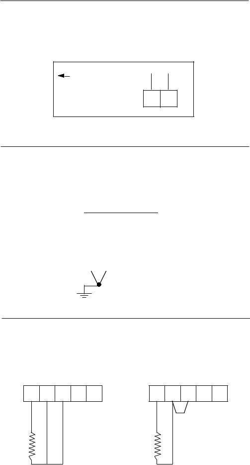
FIGURE 2-5
AC Instrument Power Input
Connect the 115 VAC hot and neutral to terminals 1 and 2 respectively of TB1. See Figure 2-4 (page 13) for Terminal Board locations on the instrument. Connect the 230 VAC one leg to each terminal, be sure to check the position of the Voltage Selector switch provided with 230 VAC instruments. The switch position must match the voltage input to the instrument.
Connect the AC ground at the green ground screw on the left side of the inside of the case
Line 1 TB1 Line 2
1 2
FIGURE 2-6
Thermocouple Inputs
Use TB4 for the Pen 1 input, and TB5 for the Pen 2 input. Connect the positive leg of the thermocouple to terminal 1, and the negative to terminal 2. Be sure that the input conditioning jumpers are properly positioned for a thermocouple input. See Appendix A-1 (page 50).
|
|
|
|
TB4 or TB5 |
|
|
|||
|
+ |
|
- |
|
|
|
|
||
|
|
|
|
|
|
||||
|
1 |
|
2 |
3 |
4 |
5 |
|
||
|
|
|
|
|
|
Grounded or |
|||
|
|
|
|
|
|
Ungrounded |
|||
|
|
|
|
|
|
Thermocouples |
|||
|
|
|
|
|
|
may be used |
|||
|
|
|
|
|
|
|
|
|
|
FIGURE 2-7
RTD Inputs
Use TB4 for the Pen 1 input, and TB5 for the Pen 2 input. Connections are shown for 3 wire and 2 wire RTD inputs. If a three wire device is used, install the common legs to terminals 2 and 3. If a two wire device is used, install a jumper between terminals 2 and 3. Be sure that the input conditioning jumpers are properly positioned for an RTD input. See Appendix A-1 (page 50).
|
TB4 or TB5 |
|
|
TB4 or TB5 |
|
||||
+ |
- |
3 |
4 |
5 |
+ |
- |
3 |
4 |
5 |
1 |
2 |
1 |
2 |
||||||
|
|
|
|
|
|
|
|
Jumper |
|
|
|
|
|
|
|
|
|
SUPPLIED BY |
|
|
|
|
|
|
|
|
|
CUSTOMER |
|
|
|
|
3 Wire RTD |
|
|
2 Wire RTD |
|||
14
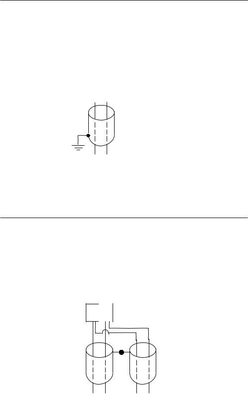
FIGURE 2-8
Volt, Millivolt and milliamp Input
Make the volt, millivolt or milliamp connections as shown below. Use TB4 for the Pen 1 input, and TB5 for the Pen 2 input. Terminal 1 is positive and terminal 2 is negative. The milliamp input requires the installation of an appropriate shunt resistor (ordered separately) between terminals 1 and 2. Be sure that input conditioning jumpers are in the correct positions for the input being connected. See Appendix A-1 (page 50).
Note: Fault Detection is not functional for 0-5V or 0-20mA Inputs.
|
|
|
|
|
|
|
|
|
TB4 or TB5 |
|
|
||||
|
|
|
|
|
|
|
|
+ |
|
- |
|
|
|
|
|
|
|
|
|
|
|
|
|
1 |
|
2 |
3 |
|
4 |
5 |
|
|
|
|
|
|
|
|
|
|
|
|
SHIELDED |
||||
|
|
|
|
|
|
|
|
|
|
|
TWISTED |
||||
|
|
|
|
|
|
|
|
|
|
|
PAIR |
|
|
||
|
|
|
|
|
|
|
|
|
|
|
|
|
MAY BE |
||
|
|
|
|
|
|
|
+ |
- |
|
|
|||||
|
|
|
|
|
|
|
|
|
GROUNDED |
||||||
|
|
|
|
|
|
|
SOURCE |
|
|||||||
|
|
|
|
|
|
|
|
OR |
|
|
|||||
|
|
|
|
|
|
|
|
|
|
|
|
|
UNGROUNDED |
||
|
|
|
|
|
|
|
|
|
|
|
|
|
|||
|
|
|
|
|
|
|
|
|
|
|
|
|
|
|
|
FIGURE 2-9
Digital Communications Options
Connections are made as shown using TB2. Refer to the Protocol Manual, Form #2878 for more details regarding the connections and how to use this option. This document is provided only when this option has been specified. If the communications network continues on to other instruments, connect the cable shields together, but not to the instrument. A terminating resistor should be installed at the terminals of the last unit in the communications loop. If the communications network ends at the instrument, the shield is not connected.
TB2
Serial A |
1 2 |
Serial B |
|
TOWARD THE |
NETWORK |
COMPUTER |
CONTINUATION |
|
(IF APPLICABLE) |
15

2.6.4 OUTPUT CONNECTIONS
Relay output(s) if provided in the instrument may be assigned to alarm output functions for Pen 1 and/or Pen 2 (if present) if instrument is recorder. Relay outputs, if instrument is a limit device, may be assigned to limit output functions. Current outputs may be assigned to process value retransmission output for Pen 1 and/or Pen 2 (if present). The assignment of the output function is accomplished in the Program mode, see Table 3-2 (page 28). SPST relay and/or SSR driver output(s) is/are designated as Relay A through Relay H. SPST relays begin with Relay A designation, then B, C, etc. SSR drivers begin with Relay H designation then G, F, etc. except when 4 SSR drivers are required in conjunction with SPDT relays, then designation E & F are not available. SSR driver designation becomes G, H, D, and C. SPDT relay output(s) are designated as Relay A and Relay B only.
FIGURE 2-10A
SPST Relay Output
Connections are made to relays A through F as shown. Terminal connections are made using TB6 (Relay/SSR Driver A, B), TB7 (Relay/SSR Driver C, D), and TB8 (Relay/SSR Driver E, F).
|
|
|
|
|
HOT |
|
|
|
|
|
|
|
|
||
|
|
|
|
|
NEU |
POWER |
|
|
|
|
|
|
|
|
|
|
|
|
|
|
LOAD |
5 AMPERES |
|
|
|
|
|
|
|
MAXIMUM |
|
1 |
2 |
3 |
4 |
|
|
||
|
|
AT 115 VAC |
|||||
N.O. |
C |
N.O. |
C |
|
|
|
|
TB6 Relay A & B, Relay A Terminals 1 & 2
TB7 Relay C & D, Relay C Terminals 1 & 2
TB8 Relay E & F, Relay D Terminals 1 & 2
FIGURE 10B
SPDT Relay Output
|
|
|
|
HOT |
|
|
|
|
|
|
|
|
|||
|
|
|
|
|
|
||
|
|
|
|
NEU |
|
POWER |
|
|
|
|
|
|
|
|
|
|
|
|
|
LOAD |
5 AMPERES |
||
1 |
2 |
3 |
|
|
MAXIMUM |
||
|
|
AT 115 VAC |
|||||
N.O. |
C |
N.C. |
|
|
|
|
|
TB6 Relay A
TB7 Relay B
FIGURE 2-11
SSR Driver Output
Connections are made to relays H through A as shown.
1 |
2 |
3 |
4 |
|
+ |
- |
|
|
SSR |
|
SOLID STATE RELAY |
||||
|
|
|
|
|
|
TB6 THRU TB9
16 |
TB9 SSRD G, H - all cases |
TB8 SSRD E, F - no SPDT relays |
|
TB8 SSRD C, D - SPDT relay/s E and F not available |
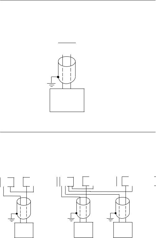
FIGURE 2-12
Current Output
Connections are made to current outputs A thru D as shown. Each current output is programmable as either 4 to 20 mADC or 0 to 20 mADC. Each output must be assigned to the desired function (refer to Table 3-2, page 28, for details.) Terminal connections are made using TB10 through TB13 for current output A through D respectively. Connect positive lead (+) to terminal 1 and the negative lead (-) to terminal 2. Current outputs will operate up to 650 ohms maximum load.
|
+ |
|
|
- |
|
|
1 |
2 |
|
|
|
SHIELDED
TWISTED
PAIR
+ -
LOAD
650 OHMS MAXIMUM
FIGURE 2-13
Transmitter Power Supply Input
If the isolated 24 VDC regulated transmitter power supply has been specified, the connections should be made as shown. Connections are made using TB3, terminal 1 is positive and terminal 2 is negative. The power supply is capable of providing the power needed by as many as 2 transmitters.
TB3 |
TB4 or TB5 |
|
TB3 |
+ |
|
TB4 |
|
|
+ |
|
TB5 |
|
|
|||||
+ |
- |
+ |
- |
3 |
4 |
5 |
+ |
- |
- |
3 |
4 |
5 |
- |
3 |
4 |
5 |
||
1 |
2 |
1 |
2 |
1 |
2 |
1 |
2 |
1 |
2 |
|||||||||
|
|
|
|
SHIELDED |
|
|
|
|
|
|
|
|
|
|
|
|
||
|
|
|
|
TWISTED |
|
|
|
|
|
|
|
|
|
|
|
|
||
|
|
|
|
|
PAIRS |
|
|
|
|
|
|
|
|
|
|
|
|
|
|
+ |
- |
|
|
|
|
|
+ |
- |
|
|
|
+ |
- |
|
|
|
|
|
TWO WIRE |
|
|
|
|
TWO WIRE |
|
|
TWO WIRE |
|
|
|
||||||
|
TRANSMITTERS |
|
|
TRANSMITTERS |
TRANSMITTERS |
|
|
|||||||||||
17

Configuration 3.1
After completing installation and wiring of the instrument the configuration (set up) procedures must be performed to prepare the instrument for operation of the intended application. The procedures include selecting specific parameters, entering data and possible jumper positioning. Once properly configured the instrument will retain the user selections in memory. This procedure need not be repeated unless required by changes in the application.
Parameter selections and data entry are made via the front keypad. To ease configuration and operation, user entered data has been divided into several sections referred to as modes. Each mode contains a different type of data or may be used for specific operating functions. For two pen instruments, some modes are common to both pens. These modes are as follows:
Operation |
Test |
Calibrate |
Program |
Alarm Set |
(oPEr) |
(tESt) |
(CAL) |
(Prog) |
(EASt) |
MODE |
DISPLAY CODE |
FUNCTION |
DESCRIPTION |
Off |
oFF |
Operation |
Limits and Alarms |
|
|
|
are Off. |
|
|
|
Chart may stop |
|
|
|
rotating(selectable) |
Operate |
oPEr |
Operation |
Limits and Alarms |
|
|
|
are Active |
Test |
tESt |
Service |
Tests Instrument |
|
|
|
Operation |
Calibration |
CAL |
Service |
Calibrates Instrument |
Program |
Prog |
Configuration |
Configure Operating |
|
|
|
Parameters |
Alarm Set |
ASEt |
Configuration & |
Enter Alarm Settings |
|
|
Operation |
|
Enable |
Enab |
Configuration |
Mode security |
|
|
|
system, can lock |
|
|
|
out everything except |
|
|
|
Off and operate |
|
|
|
(See Appendix A-1, |
|
|
|
page 50, for |
|
|
|
hardware lockout |
|
|
|
information). |
Associated with each mode is a series of unique displays which are accessed via the front keypad.
Prior to first time operation of the unit, the configuration procedures for the Program and Alarm Set modes must be performed as applicable. Calibration and Test modes are not used as part of the instrument configuration or operation. These are used for service and maintenance functions and are discussed in Section 4.6 of this manual (page 43).
18
Shipped Configuration/Jumper Positioning 3.2
Each instrument is factory shipped ready to accept a thermocouple input on TB 4 and TB 5. All configuration parameters in each mode are set to default values. These defaults are shown in tabular form after the description for each mode. Instrument AC power input is as specified in the instrument model number and is shown on the ratings label. The 230 VAC option includes a switch in the instrument for selecting either 230 VAC or115 VAC input power. If this feature is provided, verify AC input and switch position before applying power to the instrument.
3.2.1 JUMPER POSITIONING
Jumpers are used to provide a security lockout feature and to condition the sensor inputs. All jumpers are typically of the three pin type and have two functions. All jumpers are located on the instrument Processor board. The instrument board layout and jumper locations are shown in Appendix A-1 (page 50). Check the actual jumper position in the unit to be configured and verify the proper position for the intended application. .
The sensor input jumpers JU4, JU5, JU6 and JU7 condition the sensor input at a basic level. Detailed input type selection is made in the Program mode.
Operation Summary 3.3
Prior to operation the Program mode parameters and Alarm Setting(s), if used, must be selected for the application. Data and parameter entry is made by stepping through each mode and making an appropriate response or entry to each step.
3.3.1 KEYPAD OPERATION
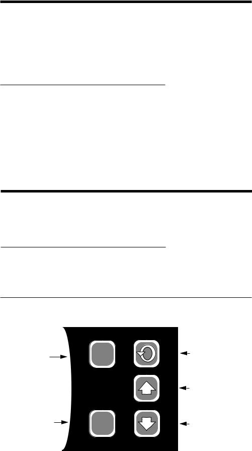
Refer to Figure 3-1 for the Keypad features. Use the SCROLL, UP and DOWN keys as indicated to program and operate the instrument.
FIGURE 3-1
Reset |
SCROLL |
|
Key |
||
Key |
||
RESET |
||
|
||
|
UP |
|
|
Key |
|
Reset |
DOWN |
|
Key |
Key |
|
|
RESET |
19

3.3.2 CONFIGURATION DISPLAYS
Each pen specified is provided with its own 4 digit LED display. These are used during configuration to display the parameter codes and values. The display located in the upper right hand corner of the instrument is used to show the codes for Pen 1 and those that are common between Pens 1 and 2. The display in the lower right hand corner is used to show the configuration codes for Pen 2 (if provided).
During normal operation, the display(s) are used to indicate process value(s) as selected in the Program mode.
3.3.3 MODE SELECTION
If the instrument is either in the Off mode or the Operation mode repeated pressing and releasing of the SCROLL key will cause the instrument to display the code corresponding to each mode that is enabled. To enter a mode, while the code is displayed, press the Down key.
Entry into any mode except the Operation and Enable modes, will cause the alarm(s) to turn off and any process retransmission value output(s) to be 0 %.
Start Up Procedure 3.4
All configuration parameters are listed in Tables 3-1 through 3-3 (pages 24-32).
For a single pen instrument, parameters for each mode are displayed in the upper right display. If the instrument being configured is a two pen model, a sequence of applicable parameters will be displayed in the Pen 2 display after the Pen 1 parameters have been reviewed and configured. After the Pen 2 parameters have been completed, parameters common to both pens will be configured and displayed in the Pen 1 display.
The instrument is provided with a time out feature. If the instrument is in any mode and no keypad activity takes place for 30 seconds, the instrument will time out and exit the mode automatically. The display will be the code for the respective mode. If a mode code is displayed for 5 seconds with no keypad activity, then the time out will cause the instrument to proceed to either the Operation or Off mode, depending upon which operational state was in use before entrance into the mode.
3.4.1 POWER UP PROCEDURE
Step 1
Verify that all electrical connections have been properly made before applying power to the unit.
Step 2A - For instruments with software revision R2.99 and below
Upon power up, 7XXX will be displayed (X representing digits), then XXXX, then XXXX, identifying the twelve digit model number as defined in the order matrix. Next, the EPROM part number will be indicated P-XX. After the EPROM part number, the software revision level will be displayed in the format rX.XX then tSt1, tSt2, and tSt3 will be displayed while Test 1 through 3 are executed automatically. Upon successful completion of these test, oPEr or oFF will be displayed for about 3 seconds. The mode displayed will be the mode the instrument was in when the power was turned off. During this time, the operator may select another mode (Alarm Set, Enable) or non-operational mode (Test, Program, Cal).
20
 Loading...