


 Loading...
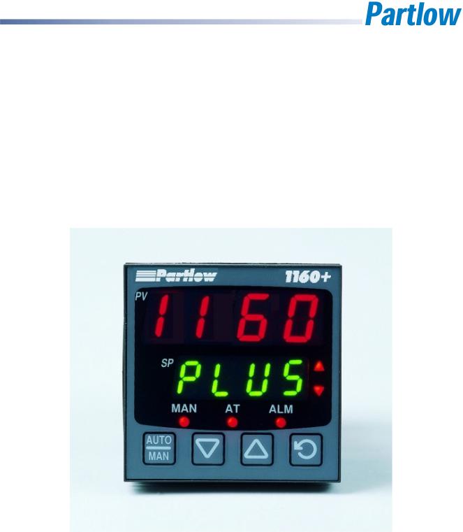
1/4 -DIN, 1/8 -DIN & 1/16 -DIN Controllers & Indicators - Product Manual
1/4, 1/8 and 1/16 DIN Plus Series
Controllers & Indicators
User Guide
Manual Part Number: 59321-5
Price: $20.00

1/4 -DIN, 1/8 -DIN & 1/16 -DIN Controllers & Indicators - Product Manual
This manual supplements the Concise Product manual supplied with each instrument at the time of shipment. Information in this installation, wiring and operation manual is subject to change without notice.
Copyright © March 2005, Danaher Corporation, all rights reserved. No part of this publication may be reproduced, transmitted, transcribed or stored in a retrieval system, or translated into any language in any form by any means without the written permission of
Partlow.
Copies of this manual are available in electronic format on the Partlow web site
(www.dancon.com) Printed versions are available from Partlow or its agents at the price published on the front cover.
Note:
It is strongly recommended that applications incorporate a high or low limit protective device, which will shut down the equipment at a preset process condition in order to prevent possible damage to property or products.
WARNING:
THE INTERNATIONAL HAZARD SYMBOL IS INSCRIBED ADJACENT TO THE REAR CONNECTION TERMINALS. IT IS IMPORTANT TO READ THIS MANUAL BEFORE INSTALLING OR COMMISSIONING THE UNIT.
Products covered by this manual are suitable for Indoor use, Installation Category II, Pollution category 2 environments.
This user guide covers the Partlow plus series product range.
Products covered in this issue of the manual:
P1400, P1160 & P1800 Process Controllers
P1401, P1161 7 P1801 Limit Controllers
P6010 & P1810 Indicators
Future editions will include other models as they are released:
59321, Issue 5 – March 2005 |
Page iii |

1/4 -DIN, 1/8 -DIN & 1/16 -DIN Controllers & Indicators - Product Manual
Warranty and Returns Statement
These products are sold by Partlow under the warranties set forth in the following paragraphs. Such warranties are extended only with respect to a purchase of these products, as new merchandise, directly from Partlow or from a Partlow distributor, representative or reseller and are extended only to the first buyer thereof who purchases them other than for the purpose of resale.
Warranty
These products are warranted to be free from functional defects in material and workmanship at the time the products leave Partlow factory and to conform at that time to the specifications set forth in the relevant Partlow instruction manuals sheet or sheets, for such products for a period of three years.
THERE ARE NO EXPRESSED OR IMPLIED WARRANTIES, WHICH EXTEND BEYOND THE WARRANTIES HEREIN AND ABOVE SET FORTH. PARTLOW MAKES NO WARRANTY OF MERCHANTABILITY OR FITNESS FOR A PARTICULAR PURPOSE WITH RESPECT TO THE PRODUCTS.
Limitations
Partlow shall not be liable for any incidental damages, consequential damages, special damages, or any other damages, costs or expenses excepting only the cost or expense of repair or replacement as described above. Products must be installed and maintained in accordance with Partlow instructions. There is no warranty against damage to the product resulting from corrosion. Users are responsible for the suitability of the products to their application.
For a valid warranty claim, the product must be returned carriage paid to the supplier within the warranty period. The product must be properly packaged to avoid damage from Electrostatic Discharge or other forms of harm during transit.
Page iv |
59321, Issue 5 – March 2005 |

1/4 -DIN, 1/8 -DIN & 1/16 -DIN Controllers & Indicators - Product Manual |
|
|
Contents |
Page Number: |
|
Warranty and Returns Statement ........................................................................................ |
iv |
|
Contents Page Number:.................................................................................................... |
v |
|
How to use this manual......................................................................................................... |
1 |
|
1 |
Introduction ................................................................................................................. |
2 |
2 |
Installation ................................................................................................................... |
3 |
|
Unpacking ..................................................................................................................... |
3 |
|
Installation ..................................................................................................................... |
3 |
|
Panel Cut-outs............................................................................................................... |
4 |
|
Panel-Mounting ............................................................................................................. |
4 |
3 |
Plug-in Options............................................................................................................ |
6 |
|
Options Modules and Functions .................................................................................... |
6 |
|
Auto Detection of Option Modules................................................................................. |
6 |
|
Preparing to Install or Remove Options Modules .......................................................... |
8 |
|
Removing/Replacing Option Modules ........................................................................... |
8 |
|
Replacing the Instrument in its Housing ...................................................................... |
11 |
4 |
Wiring Instructions.................................................................................................... |
12 |
|
Installation Considerations .......................................................................................... |
12 |
|
AC Power Wiring - Neutral (for 100 to 240V AC versions) .......................................... |
12 |
|
Wire Isolation............................................................................................................... |
12 |
|
Use of Shielded Cable................................................................................................. |
13 |
|
Noise Suppression at Source ...................................................................................... |
13 |
|
Sensor Placement (Thermocouple or RTD) ................................................................ |
14 |
|
Thermocouple Wire Identification Chart ...................................................................... |
14 |
|
Connections and Wiring .............................................................................................. |
15 |
|
Power Connections - Mains Powered Instruments ................................................. |
17 |
|
Power Connections - 24/48V AC/DC Powered Instruments .................................. |
17 |
|
Universal Input Connections - Thermocouple (T/C)................................................ |
18 |
|
Universal Input Connections - RTD input................................................................ |
18 |
|
Universal Input Connections - Linear Volt, mV or mA input .................................... |
19 |
|
Option Slot 1 - Relay Module .................................................................................. |
20 |
|
Option Slot 1 - SSR Driver Module ......................................................................... |
20 |
|
Option Slot 1 - Triac Module ................................................................................... |
20 |
|
Option Slot 1 - Linear Voltage or mADC module..................................................... |
21 |
59321, Issue 5 – March 2005 |
Page v |

|
1/4 -DIN, 1/8 -DIN & 1/16 -DIN Controllers & Indicators - Product Manual |
|
|
Option Slot 2 - Relay Module .................................................................................. |
22 |
|
Option Slot 2 - SSR Driver Module.......................................................................... |
22 |
|
Option Slot 2 - Triac Module.................................................................................... |
22 |
|
Option Slot 2 - Dual Relay Module .......................................................................... |
23 |
|
Option Slot 2 - Linear Voltage or mADC module..................................................... |
23 |
|
Option Slot 3 - Relay Module .................................................................................. |
24 |
|
Option Slot 3 - SSR Driver Module.......................................................................... |
24 |
|
Option Slot 3 - Linear Voltage or mADC module..................................................... |
24 |
|
Option Slot 3 - Dual Relay Module .......................................................................... |
25 |
|
Option Slot 3 - Transmitter Power Supply Module .................................................. |
25 |
|
Option Slot A Connections - RS485 Serial Communications Module...................... |
26 |
|
Option Slot A Connections - Digital Input Module ................................................... |
26 |
|
Option Slot A Connections – Basic RSP ................................................................. |
26 |
|
Option Slot B Connections – Heater Current Input.................................................. |
27 |
|
Option Slot B Connections – Digital Input 2 ............................................................ |
27 |
|
Option Slot B Connections – 1/4 DIN & 1/8 DIN Full RSP ......................................... |
27 |
5 |
Powering Up............................................................................................................... |
28 |
|
Powering Up Procedure............................................................................................... |
28 |
|
Overview Of Front Panel ............................................................................................. |
28 |
|
Displays ....................................................................................................................... |
29 |
|
LED Functions ............................................................................................................. |
29 |
|
Keypad ........................................................................................................................ |
29 |
6 |
Messages and Error Indications .............................................................................. |
30 |
7 |
Instrument Operation Modes.................................................................................... |
31 |
|
Select Mode................................................................................................................. |
31 |
|
Entry into the Select Mode ...................................................................................... |
31 |
|
Navigating in Select Mode ...................................................................................... |
31 |
|
Unlock Codes .............................................................................................................. |
32 |
|
Automatic Tune Mode ................................................................................................. |
32 |
|
Navigating in Automatic Tune Mode ....................................................................... |
32 |
|
Product Information Mode ........................................................................................... |
33 |
|
Navigating in the Product Information Mode ........................................................... |
33 |
|
Lock Code View........................................................................................................... |
35 |
|
Entry and Navigating in Lock Code View Mode ...................................................... |
35 |
Page vi |
59321, Issue 5 – March 2005 |

1/4 -DIN, 1/8 -DIN & 1/16 -DIN Controllers & Indicators - Product Manual |
|
|
8 |
P1160, P1800 & P1400 Controller – Model Group................................................... |
36 |
|
P1160, P1800 & P1400 Controllers - Configuration Mode .......................................... |
36 |
|
Entry into the Configuration Mode........................................................................... |
36 |
|
Scrolling through Parameters and Values............................................................... |
36 |
|
Changing Parameter Values................................................................................... |
37 |
|
P1160, P1800 & P1400 – Setup Mode........................................................................ |
43 |
|
Entry into the Setup Mode ...................................................................................... |
43 |
|
Scrolling through Parameters & Values .................................................................. |
43 |
|
Changing Parameter Values................................................................................... |
43 |
|
P1160, P1800 & P1400 Controllers - Operator Mode ................................................. |
46 |
|
P1160, P1800 & P1400 Controllers – Extended Operator Mode ............................ |
47 |
|
Navigating in Operator Mode .................................................................................. |
47 |
|
Adjusting the Local Setpoint(s).................................................................................... |
49 |
|
Adjusting the Setpoint Ramp Rate .............................................................................. |
49 |
|
Manual Control Mode .................................................................................................. |
49 |
|
Selecting/deselecting Manual Control Mode........................................................... |
49 |
|
P1160, P1800 & P1400 Controllers – Serial Communications Parameters ................ |
50 |
|
Bit Parameters ........................................................................................................ |
50 |
|
Word Parameters.................................................................................................... |
50 |
9 |
P1161, P1801 & P1401 Limit Controller – Model Group ......................................... |
55 |
|
P1161, P1801 & P1401 Limit Controllers - Configuration Mode.................................. |
55 |
|
Entry into the Configuration Mode........................................................................... |
55 |
|
Scrolling through Parameters and Values............................................................... |
55 |
|
Changing Parameter Values................................................................................... |
56 |
|
P1161, P1801 & P1401 Limit Controllers – Setup Mode............................................. |
61 |
|
Entry into the Setup Mode ...................................................................................... |
61 |
|
Scrolling through Parameters & Values .................................................................. |
61 |
|
Changing Parameter Values................................................................................... |
61 |
|
P1161, P1801 & P1401 Limit Controllers - Operator Mode......................................... |
63 |
|
Navigating in Operator Mode .................................................................................. |
63 |
|
Limit Setpoint Adjustment............................................................................................ |
63 |
|
Exceed Condition ........................................................................................................ |
64 |
|
Limit Output Function .................................................................................................. |
64 |
|
Limit Annunciator Outputs ........................................................................................... |
64 |
59321, Issue 5 – March 2005 |
Page vii |

|
1/4 -DIN, 1/8 -DIN & 1/16 -DIN Controllers & Indicators - Product Manual |
|
|
Resetting Limit Outputs & Annunciators ...................................................................... |
64 |
|
Using The Reset Key To Reset Limit Outputs & Annunciators .............................. |
64 |
|
Resetting Limit Hold and Exceed Time........................................................................ |
64 |
|
To reset the stored Limit Hold and Exceed Time values ......................................... |
64 |
|
P1161, P1801 & P1401 Controllers – Serial Communications Parameters................. |
65 |
|
Bit Parameters ........................................................................................................ |
65 |
|
Word Parameters .................................................................................................... |
65 |
10 |
P6010 & P1810 Indicator – Model Group ................................................................. |
69 |
|
P6010 & P1810 Indicators - Configuration Mode......................................................... |
69 |
|
Entry into the Configuration Mode........................................................................... |
69 |
|
Scrolling through Parameters and Values............................................................... |
70 |
|
Changing Parameter Values ................................................................................... |
70 |
|
P6010 & P1810 Indicators - Setup Mode..................................................................... |
77 |
|
Entry into the Setup Mode....................................................................................... |
77 |
|
Scrolling through Parameters and Values............................................................... |
77 |
|
Changing Parameter Values ................................................................................... |
77 |
|
P6010 & P1810 Indicators - Operator Mode................................................................ |
81 |
|
Entry into Operator Mode....................................................................................... |
81 |
|
Scrolling through Parameters and Values............................................................... |
81 |
|
Changing Parameter Values ................................................................................... |
81 |
|
1/8 Din Indicator Units Display ...................................................................................... |
83 |
|
Alarm Indications ......................................................................................................... |
83 |
|
*Resetting Latched Alarm Outputs .............................................................................. |
83 |
|
Resetting Alarm 1 Active Time, Minimum PV or Maximum PV.................................... |
83 |
|
Multi-Point Scaling....................................................................................................... |
84 |
|
Tare Feature................................................................................................................ |
84 |
|
P6010 & P1810 Indicators – Serial Communications Parameters............................... |
85 |
|
Bit Parameters ........................................................................................................ |
85 |
|
Word Parameters .................................................................................................... |
86 |
11 |
Manual Tuning of Controllers................................................................................... |
89 |
|
Controllers Fitted With Primary Output Only................................................................ |
89 |
|
Controllers Fitted With Primary and Secondary Outputs ............................................. |
90 |
|
Manual Fine Tuning..................................................................................................... |
90 |
12 |
Modbus Serial Communications .............................................................................. |
92 |
Page viii |
59321, Issue 5 – March 2005 |

1/4 -DIN, 1/8 -DIN & 1/16 -DIN Controllers & Indicators - Product Manual |
|
|||
|
Physical Layer ............................................................................................................. |
|
92 |
|
|
Link Layer.................................................................................................................... |
|
|
93 |
|
Device Addressing ...................................................................................................... |
94 |
||
|
Supported Modbus Functions...................................................................................... |
94 |
||
|
Function Descriptions.................................................................................................. |
94 |
||
|
Read Coil/Input Status (Function 01 / 02) ............................................................... |
95 |
||
|
Read Holding/Input Registers (Function 03 / 04) .................................................... |
95 |
||
|
Force Single Coil (Function 05)............................................................................... |
96 |
||
|
Pre-Set Single Register (Function 06) .................................................................... |
96 |
||
|
Loopback Diagnostic Test (Function 08)................................................................. |
96 |
||
|
Pre-Set Multiple Registers (Function 10 Hex)......................................................... |
97 |
||
|
Exception Responses ............................................................................................. |
97 |
||
13 |
ASCII Communications............................................................................................. |
98 |
||
|
Physical Layer ............................................................................................................. |
|
98 |
|
|
Device Addressing ...................................................................................................... |
98 |
||
|
Session Layer |
.............................................................................................................. |
|
98 |
|
Type 1 Message ..................................................................................................... |
99 |
||
|
Type 2 Message ................................................................................................... |
100 |
||
|
Type 3 Message ................................................................................................... |
100 |
||
|
Type 4 Message ................................................................................................... |
101 |
||
|
Error Response ......................................................................................................... |
|
101 |
|
14 |
Calibration Mode ..................................................................................................... |
102 |
||
|
Equipment Required For Checking or Calibrating the Universal Input ...................... |
102 |
||
|
Calibration Check ...................................................................................................... |
102 |
||
|
Recalibration Procedure............................................................................................ |
103 |
||
15 |
Appendix 1 – Glossary............................................................................................ |
104 |
||
|
Active Setpoint |
Type: Controller Definition.............................................................. |
104 |
|
|
Actual Setpoint |
Type: Controller Definition ............................................................ |
104 |
|
|
Alarm Hysteresis |
Type: General Parameter .......................................................... |
105 |
|
|
Alarm Operation |
Type: General Definition .............................................................. |
106 |
|
|
Alarm Inhibit |
Type: General Parameter .................................................................. |
107 |
|
|
Annunciator |
Type: Limit Controller Definition.......................................................... |
107 |
|
|
Automatic Reset (Integral) Type: Controller Tuning Parameter ............................. |
107 |
||
|
Auto Pre-Tune |
Type: Controller Tuning Parameter ............................................... |
107 |
|
59321, Issue 5 – March 2005 |
Page ix |
|
|
|
|
|
1/4 -DIN, 1/8 -DIN & 1/16 -DIN Controllers & Indicators - Product Manual |
|||
Band Alarm 1 Value |
Type: General Parameter....................................................... |
107 |
||||||
Band Alarm 2 Value |
Type: General Parameter....................................................... |
107 |
||||||
Bias (Manual Reset) |
Type: Controller Tuning Parameter........................................ |
108 |
||||||
Bumpless Transfer |
Type: Controller Definition........................................................ |
108 |
||||||
Cascade Control |
Type: Controller Definition ........................................................... |
108 |
||||||
Communications Write Enable |
Type: General Definition ........................................ |
109 |
||||||
Controller |
Type: Controller Definition ...................................................................... |
109 |
||||||
CPU |
Type: General Definition................................................................................ |
109 |
||||||
Current Proportioning Control |
Type: Controller Definition....................................... |
109 |
||||||
Cycle Time |
Type: Controller Definition.................................................................... |
109 |
||||||
Deadband |
Type: Controller Parameter .................................................................. |
109 |
||||||
Derivative |
Type: Controller Parameter.................................................................... |
109 |
||||||
Deviation Alarm 1 Value Type |
Type: General Parameter ....................................... |
109 |
||||||
Deviation Alarm 2 Value |
Type: General Parameter ................................................ |
110 |
||||||
Differential (On-Off Hysteresis) |
Type: Controller Parameter ................................... |
110 |
||||||
Direct/Reverse Operation of Control Outputs Type: Controller Definition ............... |
110 |
|||||||
Display Strategy |
Type: General Parameter............................................................. |
110 |
||||||
Elapsed Time |
Type: Indicator Definition.................................................................. |
110 |
||||||
Exceed Condition Type: Limit Controller Definition ................................................. |
110 |
|||||||
Exceed Time |
Type: Limit Controller Definition ........................................................ |
111 |
||||||
Indicator Type: Indicator Definition.......................................................................... |
111 |
|||||||
Input Filter Time Constant |
Type: General Parameter ............................................. |
111 |
||||||
Input Range |
Type: General Definition..................................................................... |
111 |
||||||
Input Span |
Type: General Definition ....................................................................... |
111 |
||||||
Integral |
Type: Controller Tuning Parameter ........................................................... |
111 |
||||||
Latching Relay |
Type: General Definition................................................................. |
111 |
||||||
LED |
Type: General Definition ............................................................................... |
111 |
||||||
Limit Controller |
Type: Limit Controller Definition ..................................................... |
112 |
||||||
Limit Hysteresis |
Type: Limit Controller Definition.................................................... |
112 |
||||||
Limit Setpoint |
Type: Limit Controller Definition ....................................................... |
112 |
||||||
Lock Codes |
|
Type: General Parameter................................................................... |
112 |
|||||
Logical Combination of Alarms |
Type: General Definition....................................... |
113 |
||||||
Loop Alarm Enable |
Type: Controller Parameter .................................................... |
113 |
||||||
Loop Alarm Time |
Type: Controller Parameter......................................................... |
114 |
||||||
Page x |
59321, Issue 5 – March 2005 |

1/4 -DIN, 1/8 -DIN & 1/16 -DIN Controllers & Indicators - Product Manual
mADC |
Type: General Definition............................................................................. |
|
114 |
||||||
Manual Mode Enable |
Type: Controller Parameter.................................................. |
114 |
|||||||
Master & Slave |
Type: Controller Definition ............................................................. |
114 |
|||||||
Multi-Point Scaling Enable |
Type: Indicator Parameter............................................ |
114 |
|||||||
Multi-Point Scaling Set Up |
Type: Indicator Parameter............................................ |
115 |
|||||||
Offset |
Type: Controller Parameter .......................................................................... |
|
115 |
||||||
On-Off Control |
Type: Controller Definition ............................................................. |
115 |
|||||||
On-Off Differential (Hysteresis) |
Type: Controller Parameter.................................. |
115 |
|||||||
Overlap/Deadband |
Type: Controller Parameter..................................................... |
116 |
|||||||
PID |
Type: Controller Definition ............................................................................. |
|
117 |
||||||
PLC |
Type: General Definition ............................................................................... |
|
117 |
||||||
Pre-Tune Type: Controller Definition ..................................................................... |
|
117 |
|||||||
Primary Output Power Limit |
Type: Controller Parameter........................................ |
118 |
|||||||
Primary Proportional Band |
Type: Controller Tuning Parameter............................. |
118 |
|||||||
Process High Alarm 1 Value |
|
Type: General Parameter......................................... |
118 |
||||||
Process High Alarm 2 Value |
|
Type: General Parameter......................................... |
119 |
||||||
Process Low Alarm 1 Value |
Type: General Parameter ......................................... |
119 |
|||||||
Process Low Alarm 2 Value |
Type: General Parameter ......................................... |
119 |
|||||||
Process Variable (PV) |
Type: General Definition ..................................................... |
119 |
|||||||
Process Variable Offset |
Type: General Parameter................................................ |
119 |
|||||||
Rate (Derivative) |
|
Type: Controller Tuning Parameter............................................ |
119 |
||||||
Remote Setpoint (RSP) |
Type: Controller Definition ................................................ |
120 |
|||||||
Remote Setpoint Input Range |
Type: Controller Parameter..................................... |
120 |
|||||||
Remote Setpoint Lower Limit |
|
Type: Controller Parameter..................................... |
120 |
||||||
Remote Setpoint Upper Limit |
|
Type: Controller Parameter..................................... |
120 |
||||||
Remote Setpoint Offset |
|
Type: Controller Parameter ............................................. |
120 |
||||||
Retransmit Output |
Type: General Definition .......................................................... |
120 |
|||||||
Retransmit Output 1 Scale Maximum |
Type: General Parameter ............................ |
121 |
|||||||
Retransmit Output 1 Scale Minimum |
Type: General Parameter ............................ |
121 |
|||||||
Retransmit Output 2 Scale Maximum |
Type: General Parameter ........................... |
121 |
|||||||
Retransmit Output 2 Scale Minimum |
Type: General Parameter ............................ |
121 |
|||||||
Retransmit Output 3 Scale Maximum |
Type: General Parameter ........................... |
121 |
|||||||
Retransmit Output 3 Scale Minimum |
Type: General Parameter ............................ |
122 |
|||||||
Reset |
Type: Controller Tuning Parameter ............................................................. |
122 |
|||||||
59321, Issue 5 – March 2005 |
Page xi |

|
|
|
1/4 -DIN, 1/8 -DIN & 1/16 -DIN Controllers & Indicators - Product Manual |
|||
|
Scale Range Upper Limit |
Type: General Parameter.............................................. |
122 |
|||
|
Scale Range Lower Limit |
Type: General Parameter.............................................. |
122 |
|||
|
Secondary Proportional Band |
Type: Controller Tuning Parameter ........................ |
122 |
|||
|
Self-Tune Type: Controller Tuning Definition ......................................................... |
123 |
||||
|
Serial Communications Option |
Type: General Definition ........................................ |
123 |
|||
|
Setpoint |
Type: Controller Definition ....................................................................... |
123 |
|||
|
Setpoint Upper Limit |
Type: Controller Parameter ................................................... |
124 |
|||
|
Setpoint Lower Limit |
Type: Controller Parameter .................................................. |
124 |
|||
|
Setpoint Ramping Enable |
Type: Controller Parameter .......................................... |
124 |
|||
|
Setpoint Ramp Rate |
Type: Controller Parameter................................................... |
124 |
|||
|
Setpoint Select Type: Controller Parameter........................................................... |
125 |
||||
|
Setpoint Select Enable |
Type: Controller Parameter............................................... |
125 |
|||
|
Solid State Relay (SSR) |
Type: General Definition ................................................. |
125 |
|||
|
Tare Type: Indicator Parameter ............................................................................. |
125 |
||||
|
Time Proportioning Control Type: Controller Definition.......................................... |
126 |
||||
|
Tuning |
Type: Controller Definition.......................................................................... |
126 |
|||
|
Triac |
Type: General Definition .............................................................................. |
126 |
|||
16 |
Appendix 2 - Specification...................................................................................... |
|
127 |
|||
|
Universal Input........................................................................................................... |
|
|
|
127 |
|
|
General Input Specifications ................................................................................. |
|
127 |
|||
|
Thermocouple ....................................................................................................... |
|
|
|
127 |
|
|
Thermocouple Ranges Available ................................................................................ |
|
127 |
|||
|
Thermocouple Performance........................................................................................ |
|
128 |
|||
|
Resistance Temperature Detector (RTD).............................................................. |
128 |
||||
|
RTD Ranges Available................................................................................................ |
|
|
|
128 |
|
|
RTD Performance ....................................................................................................... |
|
|
|
129 |
|
|
DC Linear.............................................................................................................. |
|
|
|
129 |
|
|
DC Linear Ranges Available ....................................................................................... |
|
129 |
|||
|
DC Linear Performance .............................................................................................. |
|
|
129 |
||
|
Remote Setpoint Input |
............................................................................................... |
|
|
130 |
|
|
Digital Inputs.............................................................................................................. |
|
|
|
130 |
|
|
Output Specifications................................................................................................. |
|
|
|
131 |
|
|
Output Module Types............................................................................................ |
|
|
131 |
||
|
Specifications of Output Types.............................................................................. |
131 |
||||
Page xii |
59321, Issue 5 – March 2005 |

1/4 -DIN, 1/8 -DIN & 1/16 -DIN Controllers & Indicators - Product Manual |
|
|
|
Control Specifications................................................................................................ |
132 |
|
Process Alarms ......................................................................................................... |
133 |
|
Digital Communications............................................................................................. |
133 |
|
Reference Conditions................................................................................................ |
133 |
|
Operating Conditions................................................................................................. |
133 |
|
Standards .................................................................................................................. |
134 |
|
Physical Specifications.............................................................................................. |
134 |
17 |
Appendix 3 - Product Coding ................................................................................. |
135 |
59321, Issue 5 – March 2005 |
Page xiii |

|
1/4 -DIN, 1/8 -DIN & 1/16 -DIN Controllers & Indicators - Product Manual |
|
List of Figures |
Page Number: |
|
Figure 1. |
Main dimensions................................................................................................. |
3 |
Figure 2. |
Panel cut-out sizes ............................................................................................. |
4 |
Figure 3. |
Panel-Mounting the instrument........................................................................... |
4 |
Figure 4. |
Typical rear view (uncased) & main board positions .......................................... |
6 |
Figure 5. |
Location of Option Modules - 1/16 DIN Instruments ............................................. |
8 |
Figure 6. |
Location of Option Modules - 1/8 & 1/4 DIN Instruments ...................................... |
9 |
Figure 7. |
Option Module Connectors - 1/16 DIN Instruments .............................................. |
9 |
Figure 8. |
Option Module Connectors - 1/8 & 1/4 DIN Instruments ..................................... |
10 |
Figure 9. |
Transient suppression with inductive coils........................................................ |
13 |
Figure 10. |
Contact noise suppression ............................................................................... |
13 |
Figure 11. |
Rear terminals (1/16-DIN Instruments)............................................................... |
15 |
Figure 12. |
Rear terminals (1/4-DIN & 1/8-DIN Instruments)................................................. |
16 |
Figure 13. |
Mains Power Connections ................................................................................ |
17 |
Figure 14. |
24/48V AC/DC Power Connections .................................................................. |
17 |
Figure 15. |
Thermocouple Input Connections..................................................................... |
18 |
Figure 16. |
RTD Input Connections .................................................................................... |
18 |
Figure 17. |
DC Volt, mV & mA Input Connections .............................................................. |
19 |
Figure 18. |
Option Slot 1 – Relay Module ........................................................................... |
20 |
Figure 19. |
Option Slot 1 - SSR Driver Module ................................................................... |
20 |
Figure 20. |
Option Slot 1 - Triac Module ............................................................................. |
20 |
Figure 21. |
Option Slot 1 - Linear Voltage & mADC Module ............................................... |
21 |
Figure 22. |
Option Slot 2 - Relay Module............................................................................ |
22 |
Figure 23. |
Option Slot 2 - SSR Driver Module ................................................................... |
22 |
Figure 24. |
Option Slot 2 - Triac Module ............................................................................. |
22 |
Figure 25. |
Option Slot 2 - Dual Relay Module ................................................................... |
23 |
Figure 26. |
Option Slot 2 - Linear Voltage & mADC module ............................................... |
23 |
Figure 27. |
Option Slot 3 - Relay Module............................................................................ |
24 |
Figure 28. |
Option Slot 3 - SSR Driver Module ................................................................... |
24 |
Figure 29. |
Option Slot 3 - Linear Voltage & mADC module ............................................... |
24 |
Figure 30. |
Option Slot 3 - Dual Relay Module ................................................................... |
25 |
Figure 31. |
Option Slot 3 - Transmitter Power Supply Module............................................ |
25 |
Figure 32. |
Option Slot A – RS485 Serial Communications Module ................................... |
26 |
Figure 33. |
Option Slot A – Digital Input Module................................................................. |
26 |
Page xiv |
59321, Issue 5 – March 2005 |

1/4 -DIN, 1/8 -DIN & 1/16 -DIN Controllers & Indicators - Product Manual |
|
|
Figure 34. Option Slot A – Basic RSP Input Module ......................................................... |
26 |
|
Figure 35. Option Slot B – Heater Current Input Connections........................................... |
27 |
|
Figure 36. Option Slot B – Digital Input 2 Connections ..................................................... |
27 |
|
Figure 37. Option Slot B – Full Remote Setpoint Input Connections ................................. |
27 |
|
Figure 38. Typical front panel and keys............................................................................. |
29 |
|
Figure 39. |
Manual Tuning.................................................................................................. |
89 |
Figure 40. Modbus Link Layer ........................................................................................... |
93 |
|
Figure 41. Alarm Hysteresis Operation............................................................................ |
105 |
|
Figure 42. |
Alarm Operation ............................................................................................. |
106 |
Figure 43. Overlap and Deadband .................................................................................. |
116 |
|
Figure 44. |
Pre-Tune Operation........................................................................................ |
118 |
Figure 45. |
Self-Tune Operation ....................................................................................... |
123 |
59321, Issue 5 – March 2005 |
Page xv |

1/4 -DIN, 1/8 -DIN & 1/16 -DIN Controllers & Indicators - Product Manual
List of Tables |
|
|
|
|
Page Number: |
|
Table 1. |
Option Module vs. Model Matrix ......................................................................... |
7 |
||||
Table 2. |
Thermocouple Extension Wire Colours ............................................................ |
14 |
||||
Table 3. |
Typical LED functions....................................................................................... |
|
29 |
|||
Table 4. |
Error/Faults conditions...................................................................................... |
|
30 |
|||
Table 5. |
Model Groups |
................................................................................................... |
|
|
31 |
|
Table 6. |
Select Mode Menus.......................................................................................... |
|
31 |
|||
Table 7. |
Lock Code – Entry .............................................................and Default Values |
32 |
||||
Table 8. |
Automatic Tune ...................................................................Mode Parameters |
33 |
||||
Table 9. |
Product Information .............................................................Mode Parameters |
33 |
||||
Table 10. |
Lock Code View ......................................................................................Menu |
|
35 |
|||
Table 11. |
P1160, |
P1800 ................................ |
& |
P1400 |
Configuration Mode Parameters |
37 |
Table 12. |
P1160, |
P1800 ........................................... |
& |
P1400 |
Set Up Mode Parameters |
44 |
Table 13. |
P1160, |
P1800 ............................................. |
& |
P1400 |
Operator Mode Displays |
47 |
Table 14. |
P1160, |
P1800 .............................. |
& |
P1400 |
Communications - Bit Parameters |
50 |
Table 15. |
P1160, |
P1800 ......................... |
& |
P1400 |
Communications - Word Parameters |
50 |
Table 16. |
P1161, |
P1801 ................................ |
& |
P1401 |
Configuration Mode Parameters |
56 |
Table 17. |
P1161, |
P1801 ........................................... |
& |
P1401 |
Set Up Mode Parameters |
62 |
Table 18. |
P1161, |
P1801 ............................................. |
& |
P1401 |
Operator Mode Displays |
63 |
Table 19. |
P1161, |
P1801 .............................. |
& |
P1401 |
Communications - Bit Parameters |
65 |
Table 20. |
P1161, |
P1801 ......................... |
& |
P1401 |
Communications - Word Parameters |
65 |
Table 21. |
P6010 |
& P1810 ............................................ |
Configuration Mode Parameters |
70 |
||
Table 22. |
P6010 |
& P1810 ...................................................... |
Set Up Mode Parameters |
78 |
||
Table 23. |
P6010 |
& P1810 ........................................................ |
Operator Mode Displays |
82 |
||
Table 24. |
P6010 |
& P1810 ......................................... |
Communications - Bit Parameters |
85 |
||
Table 25. |
P6010 |
& P1810 ..................................... |
Communications - Word Parameters |
86 |
||
Table 26. |
Supported Modbus ...........................................................................Functions |
94 |
||||
Table 27. |
Read Coil/Input .............................................Status (Modbus Function 01/02) |
95 |
||||
Table 28. |
Read Holding/Input ..................................Registers (Modbus Function 03/04) |
95 |
||||
Table 29. |
Force Single Coil ..........................................................(Modbus Function 05) |
96 |
||||
Table 30. |
Pre-Set Single ................................................Register (Modbus Function 06) |
96 |
||||
Table 31. |
Loopback Diagnostic .............................................Test (Modbus Function 08) |
96 |
||||
Table 32. |
Pre-Set Multiple .....................................Registers (Modbus Function 10 Hex) |
97 |
||||
Table 33. |
Modbus Exception .........................................................................Responses |
97 |
||||
Page xvi |
59321, Issue 5 – March 2005 |

1/4 -DIN, 1/8 -DIN & 1/16 -DIN Controllers & Indicators - Product Manual |
|
|
Table 34. |
ASCII Parameter Key ....................................................................................... |
99 |
Table 35. |
ASCII Data Element – Sign/Decimal Point Position ......................................... |
99 |
Table 36. |
Input Calibration phases................................................................................. |
103 |
Table 37. |
Logical Alarm Outputs .................................................................................... |
113 |
59321, Issue 5 – March 2005 |
Page xvii |

1/4 -DIN, 1/8 -DIN & 1/16 -DIN Controllers & Indicators - Product Manual
How to use this manual
This manual is structured to give easy access to the information required for all aspects of the installation and use and of the products:
Section 1: Introduction - A brief description of the product range.
Section 2: Installation - Unpacking, installing and panel mounting instructions.
Section 3: Plug-in Options - Installation of the plug-in option modules.
Section 4: Wiring Guidelines - Guidance on good wiring practice, noise avoidance, wiring diagrams and input/output connections.
Section 5: Powering Up - Powering up procedure and brief description of the displays and switches.
Section 6: Messages & Error Indications - Display Messages and fault indications.
Section 7: Operation Modes - Descriptions of the operation modes common across the range. These include Select Mode for gaining access to the Setup and Configuration menus,
Automatic tuning on controllers and the Product information menu.
Section 8: P1160, P1800 & P1400 Model Group - Describes the menus and features unique to the process controllers in this model group. These include Configuration Mode, Setup Mode & Operator Mode menus, and the serial communications parameters. Also detailed is Setpoint adjustment, use of Manual Control Mode and automatic PID tuning.
Section 9: P1161, P1801 & P1401 Model Group - Describes the menus and features unique to the limit controllers in this model group. These include Configuration Mode, Setup Mode & Operator Mode menus, and the serial communications parameters. Also detailed is adjustment of the Limit Setpoint and resetting the Limit Output.
Section 10: P6010 & P1810 Model Group - Describes the menus and features unique to the indicators in this model group. These include Configuration Mode, Setup Mode & Operator Mode menus, and the serial communications parameters. Also detailed the Tare and Multi-Point Scaling Functions.
Section 11: Manually Tuning Controllers - Advice on manually adjusting the PID controller tuning parameters.
Section 12: Modbus Serial Communications - Details the physical layer and message formats used for the Modbus communications protocol common to all products in the range.
Section 13: ASCII Serial Communications - Details the physical layer and message formats used for the ASCII serial communications protocol available on some products.
Section 14: Calibration Mode - Step-by-step instructions to calibrate the instrument. This section is intended for use by suitably qualified personnel.
Appendix 1: Glossary - Explanations of the terms used and product features.
Appendix 2: Specification - Technical specifications for all products in the range.
Appendix 3: Product Coding - Product model/ordering codes.
59321, Issue 5 – March 2005 |
Page 1 |
1/4 -DIN, 1/8 -DIN & 1/16 -DIN Controllers & Indicators - Product Manual
1 Introduction
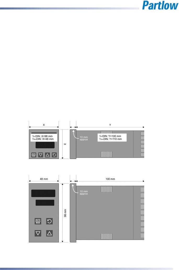
These instruments are microprocessor based indicators, process controllers, indicators, and profilers. They can measure, display or control process variables such as temperature, pressure, flow and level from a variety of inputs. Models are available in three sizes. 1/16 DIN (48 x 48mm front). 1/8 DIN (48 x 96mm front) and 1/4 DIN (96 x 96mm front).
The operating voltage is either 100-240V at 50/60 Hz or 24V-48V AC/DC depending on the model purchased. EEPROM technology protects against data or configuration loss during power outages.
Inputs are user configurable for connection to thermocouple and RTD probes, as well as linear process signal types such as mVDC, VDC or mADC. Output options include relays, SSR drivers, triacs or linear mV/voltage modules. These can be used for process control, alarms or retransmission of the process variable or setpoint to external devices such as data recorders or PLC’s. A Transmitter Power Supply option module can provide an unregulated
24V DC (22mA) auxiliary output voltage for external signal transmitters.
Alarm indication is standard on all instruments; up to five alarms are possible on the indicators. Alarms may be set as process high or low, deviation (active above or below controller setpoint), band (active both above and below setpoint), or control loop types. Models with a heater current input also have high, low or short circuit heater break alarms based on control load current. These alarms can be linked to any suitable output. Alarm status is indicated by LED’s or the alarm status screen.
Controllers can be programmed for on-off, time proportioning, or current proportioning control implementations, depending on the output modules fitted, and feature manual or automatic tuning of the PID parameters. A secondary control output is available when additonal output modules are fitted. Valve Motor Drive (VMD) is also possible on some models. Controllers with analogue Remote Setpoint inputs and Profile Controllers are included in the range. Control functions, alarm settings and other parameters are easily adjusted from the front keypad or via PC based configuration software.
Limit Controllers shut down a process in order to prevent possible damage to equipment or products. They have latching relay, which cannot be reset until the process is in a safe condition. Limit controllers work independently of the normal process controller and have approvals for safety critical applications.
Indicator models can display a process value and provide multiple stage alarm outputs. Additional features include Multipoint scaling to compensate for non-linear signals and a Tare function to auto-zero the current reading.
Page 2 |
Introduction |
59321, Issue 5 – March 2005 |
1/4 -DIN, 1/8 -DIN & 1/16 -DIN Controllers & Indicators - Product Manual
2 Installation
Unpacking
1.Remove the product from its packing. Retain the packing for future use, in case it is necessary to transport the instrument to a different site or to return it to the supplier for repair/testing.
2.The instrument is supplied with a panel gasket and push fit fixing strap. A single sheet concise manual is also supplied in one or more languages. Examine the delivered items for damage or defects. If any are found, contact your supplier immediately.
Installation
CAUTION:
Installation and configuration should be performed only by personnel who are technically competent and authorised to do so. Local regulations regarding electrical installation and safety must be observed.
1/4 - DIN & 1/16 - DIN Instruments
1/8 - DIN Instruments
Figure 1. Main dimensions
59321, Issue 5 – March 2005 |
Installation |
Page 3 |
1/4 -DIN, 1/8 -DIN & 1/16 -DIN Controllers & Indicators - Product Manual
Panel Cut-outs
The mounting panel must be rigid and may be up to 6.0mm (0.25 inches) thick. The cut-outs required for the instruments are shown below.
|
1/4 DIN |
|
1/8 DIN |
|
1/16 DIN |
|||
|
|
|
|
|
92mm |
|
|
|
|
|
|
|
|
|
|
|
|
92mm |
|
|
|
|
+0.5 –0.0 |
|
|
|
+0.5 –0.0 |
|
|
|
|
(45mm for |
|
|
45mm |
|
|
|
|
|
||||
|
|
|
|
|
indicator) |
|
|
|
|
|
|
|
|
|
|
+0.5 –0.0 |
|
|
|
|
|
|
|
|
|
|
|
|
|
|
|
|
|
|
|
|
92mm |
45mm +0.5 –0.0 |
|
|
45mm |
|||
|
+0.5 –0.0 |
(92mm for indicator) |
|
+0.5 –0.0 |
||||
|
|
|
|
|
|
|
|
|
Figure 2. Panel cut-out sizes
Panel-Mounting
CAUTION:
Ensure the inside of the panel is with the instruments operating temperature and that there is adequate air flow to prevent overheating.
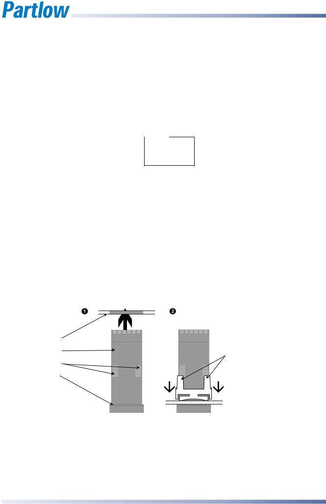
|
Slide mounting clamp over the |
|
|
instrument housing, towards rear face of |
|
Mounting Panel |
mounting panel, until the tongues |
|
engage in ratchets and instrument is |
||
|
||
Instrument Housing |
clamped in position. |
|
Ratchets |
|
|
Gasket |
|
|
Hold firmly in position |
||
|
||
|
(apply pressure to bezel only) |
Figure 3. Panel-Mounting the instrument
CAUTION:
Do not remove the panel gasket, as this may result in inadequate clamping and sealing of the instrument to the panel.
Page 4 |
Installation |
59321, Issue 5 – March 2005 |

1/4 -DIN, 1/8 -DIN & 1/16 -DIN Controllers & Indicators - Product Manual
Once the instrument is installed in its mounting panel, it may be subsequently removed from it’s housing, if necessary, as described in the Fitting and Removing Option Modules section.
Instruments may be mounted side-by-side in a multiple installation, but instrument to panel moisture and dust sealing will be compromised. The cut-out width (for n instruments) is shown below.
1/8 - & 1/16 - DIN Instruments (excluding 1/8 - DIN Indicators):
(48n - 4) mm or (1.89n - 0.16) inches.
1/4 - DIN Instruments & 1/8 - DIN Indicators:
(96n - 4) mm or (3.78n - 0.16) inches
If panel sealing must be maintained, mount each instrument into an individual cut-out with 6mm or more clearance between the edges of the holes.
Note:
The mounting clamp tongues may engage the ratchets either on the sides or the top/bottom faces of the Instrument housing. When installing several Instruments side-by- side in one cut-out, use the ratchets on the top/bottom faces.
59321, Issue 5 – March 2005 |
Installation |
Page 5 |
1/4 -DIN, 1/8 -DIN & 1/16 -DIN Controllers & Indicators - Product Manual
3 Plug-in Options
Options Modules and Functions
A range of plug-in option modules is available to add additional input, output and communication functions to the instruments in the range. These modules can be either preinstalled at the time of manufacture, or retrofitted in the field.
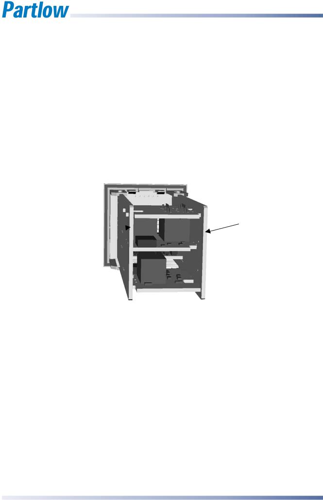
The modules are installed between the instruments main circuit boards into the four option slots. These are designated as Slots 1, 2, 3, A & B. Installation is detailed below.
Note:
Slot 1 modules cannot be fitted into Slot 2 or 3. Slot 2 & 3 modules cannot be fitted into Slot 1. Some Slot 2 &3 modules should only be fitted into one of the two slots. This is detailed in the - Option Module vs. Model Matrix below.
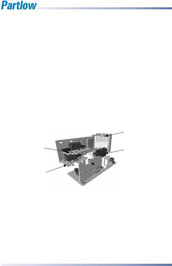
PSU BOARD
CPU BOARD 
Figure 4. Typical rear view (uncased) & main board positions
Auto Detection of Option Modules
The instrument automatically detects which option modules have been fitted into each slot.
In Configuration Mode, the menus will change to reflect the options compatible with the hardware fitted. The modules fitted can be viewed in the Product Information Mode.
Page 6 |
Plug-in Options |
59321, Issue 5 – March 2005 |

1/4 -DIN, 1/8 -DIN & 1/16 -DIN Controllers & Indicators - Product Manual
|
Table 1. |
Option Module vs. Model Matrix |
|
|
|||||
|
|
|
|
|
|
|
|
|
|
|
|
|
|
|
MODEL NUMBER |
|
|
|
|
MODULE PART |
P1160 |
P1800 |
|
P1400 |
P1161 |
P1801 |
P1401 |
P6010 |
P1810 |
& Function |
|
||||||||
NUMBER |
|
|
|
|
|
|
|
|
|
|
|
|
|
|
|
|
|
|
|
OPTION
SLOT 1
PO1-C10
Relay
PO1-C50
SSR Driver
PO1-C80
Triac
PO1-C21
Linear mA/V DC
OPTION
SLOT 2
PO2-C10
Relay
PO2-C50
SSR Driver
PO2-C80 |
Triac |
PO2-C21 |
Linear mA/V DC |
PO2-W09 |
Dual Relay |
OPTION |
SLOT 3 |
PO2-C10 |
Relay |
PO2-C50 |
SSR Driver
PO2-C21
Linear mA/V DC
PO2-W08
TransmitterPSU
PO2-W09
Dual Relay
OPTION
SLOT A
PA1-W06
RS485 Comms
PA1-W03
Digital Input
PA1-W04 |
Basic RSP Input |
OPTION |
SLOT B |
PB1-W0R |
Full RSP Input |
SOFTWARE & |
ACCESSORIES |
PS2-CON |
Config Software |
KEY |
Option Possible |
|
Option Not Possible |
|
|
59321, Issue 5 – March 2005 |
Plug-in Options |
Page 7 |
1/4 -DIN, 1/8 -DIN & 1/16 -DIN Controllers & Indicators - Product Manual
Preparing to Install or Remove Options Modules
CAUTION:
Before removing the instrument from it’s housing, ensure that all power has been removed from the rear terminals.
1.Remove the instrument from its housing by gripping the side edges of the front panel
(there is a finger grip on each edge) and pull the instrument forwards. This will release the instrument from the rear connectors in the housing and will give access to the PCBs.
2.Take note of the orientation of the instrument for subsequent replacement into the housing. The positions of the main and option PCBs in the instrument are shown below.
Removing/Replacing Option Modules
With the instrument removed from its housing:
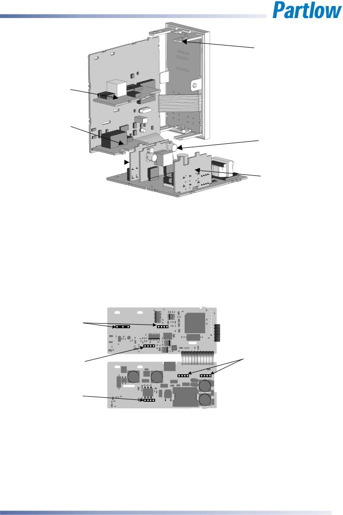
1.To remove or replace modules into Option Slots 1,A or B, it is necessary to gently separate the CPU and PSU PCBs. This is achieved by detaching the main boards (PSU and CPU) from the front moulding by lifting first the upper, and then lower mounting struts as shown. This frees the boards from the front. If only Option slots 2 or 3 are to be changed, this stage is not required as these slots are accessible without separating the main boards from the front.
Mounting Struts
Option Slot 1 |
Option Slot A |
|
 Option Slot 3
Option Slot 2
Figure 5. Location of Option Modules - 1/16 DIN Instruments
CAUTION:
Take care not to put undue stress on the ribbon cable attaching the display and CPU boards.
Page 8 |
Plug-in Options |
59321, Issue 5 – March 2005 |
1/4 -DIN, 1/8 -DIN & 1/16 -DIN Controllers & Indicators - Product Manual
Mounting Struts
Option Slot B
Option Slot 2
Option Slot A
Option Slot 1 
Option Slot 3
Figure 6. Location of Option Modules - 1/8 & 1/4 DIN Instruments
CAUTION:
Take care not to put undue stress on the ribbon cable attaching the display and CPU boards.
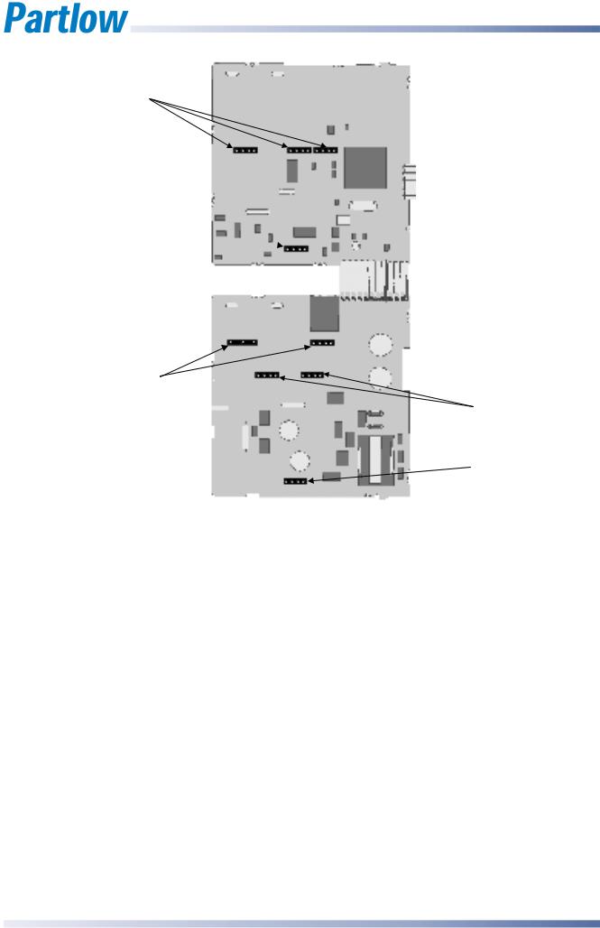
2.Remove or fit the modules into the Option slots as required. The location of the connectors is shown below. Tongues on each option module locate into a slots cut into the main boards, opposite each of the connectors.
Option Slot 1 |
|
Connectors PL7 & PL8 |
|
Option Slot 2 |
Option Slot A |
Connector PL4A |
Connectors PL5 & PL6 |
Option Slot 3 |
|
Connector PL4B |
|
Figure 7. Option Module Connectors - 1/16 DIN Instruments
CAUTION:
Check for correct orientation of the modules and that all pins locate correctly into the socket
59321, Issue 5 – March 2005 |
Plug-in Options |
Page 9 |
1/4 -DIN, 1/8 -DIN & 1/16 -DIN Controllers & Indicators - Product Manual
Option Slot B
Connectors PL2A,
PL2B & PL2C
Option Slot 2
Connector PL4A 
Option Slot 1 |
|
Connectors PL7 & PL8 |
Option Slot A |
|
|
|
Connectors PL5 & PL6 |
|
Option Slot 3 |
|
Connectors PL4B |
Figure 8. Option Module Connectors - 1/8 & 1/4 DIN Instruments
CAUTION:
Check for correct orientation of the modules and that all pins locate correctly into the socket
Page 10 |
Plug-in Options |
59321, Issue 5 – March 2005 |

1/4 -DIN, 1/8 -DIN & 1/16 -DIN Controllers & Indicators - Product Manual
Replacing the Instrument in its Housing
With the required option modules correctly located into their respective positions the instrument can be replaced into its housing as follows:
1.If required, move the CPU and PSU boards back together, taking care to locate the option module tongues into the slots in the board opposite. Hold the main boards together whilst relocating them back into the mounting struts on the front panel.
2.Align the CPU and PSU PCBs with their guides and connectors in the housing.
3.Slowly and firmly, push the instrument in position.
CAUTION:
Ensure that the instrument is correctly orientated. A mechanical stop will operate if an attempt is made to insert the instrument in the wrong orientation, this stop MUST NOT be over-ridden.
59321, Issue 5 – March 2005 |
Plug-in Options |
Page 11 |
Loading...