

Page 1

4877
Valve Controller
Operating Instruction Manual
598M
Page 2

Valve Controllers
Preface
Related Instructions — 2
Scope — 2
Applications — 2
Explanation of Symbols — 3
Safety Information — 3
Intended Usage — 3
Unpack Carefully — 3
Cleaning & Maintenance — 4
Provisions for Lifting and Carrying — 4
General Specifi cations — 4
Electrical Ratings— 4
Environmental Conditions— 4
Installation
General Instructions — 5
Main power switch — 5
Air Supply — 6
Reactor Outlet — 6
Protective Fuses — 6
Fuses— 6
Parts List
Fuses — 7
Control Cables — 7
Mains Supply Cords — 7
Valve Control Connections — 7
Air Supply Connections — 7
Preface
Related Instructions
The following Parr publications are also included to
further your understanding of this instrument and
its component parts:
No. Description
201M Limited Warranty
535M 4871 Supplemental Instructions
Scope
These instructions cover the installation and
operation of Parr model 4877 Valve Controller as
used with Parr Laboratory Reactors and Pressure
Vessels. The users should study the instructions
carefully before using any of these controllers so
that they will fully understand the capabilities of
this equipment and the safety precautions to be
observed in its operation.
Applications
These units are designed specifi cally for use with
Parr reactors and pressure vessels and are to be
used only with Parr equipment.
Figures
Valve Controller Front Panel — 5
Valve Controller Back Panel— 6
Questions concerning the installation or operation of this instrument
can be answered by the Parr Customer Service Department:
2
Parr Instrument Company
Customer Service
1-309-762-7716 • 1-800-872-7720 • Fax: 1-309-762-9453
E-mail: parr@parrinst.com • http://www.parrinst.com
Page 3
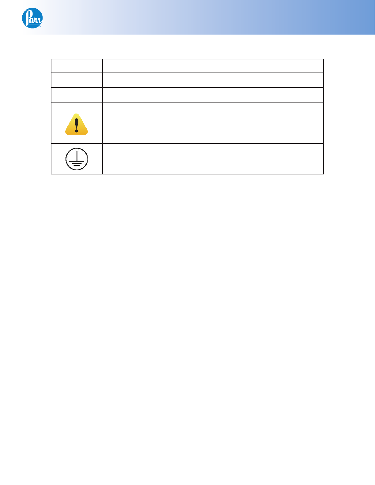
Explanation of Symbols
I On position
O Off Position
~ Alternating Current (AC)
Valve Controllers
This CAUTION symbol may be present on the Product Instrumentation
and literature. If present on the product, the user must consult the appropriate part of the accompanying product literature for more information.
Protective Earth (PE) terminal. Provided for connection of the protec-
tive earth (green or green/yellow) supply system conductor.
Safety Information
To avoid electrical shock, always:
1. Use a properly grounded electrical outlet of
correct voltage and current handling capability.
2. Ensure that the equipment is connected to
electrical service according to local national
electrical codes. Failure to properly connect may
create a fi re or shock hazard.
3. For continued protection against possible
hazard, replace fuses with same type and rating
of fuse.
4. Disconnect from the power supply before
maintenance or servicing.
To avoid personal injury:
1. Do not use in the presence of fl ammable or
combustible materials; fi re or explosion may
result. This device contains components which
may ignite such material.
2. Refer servicing to qualifi ed personnel.
Intended Usage
This controller has been designed for use with Parr
Pressure Vessels and Reactors. It has been designed, built, and tested to strict physical and electrical standards. However, it is the user’s responsibility to install and operate it in conformance with local
pressure and electrical codes.
If the instrument is used in a manner not specifi ed
by Parr Instrument Company, the protection provided by the equipment may be impaired.
Establish training procedures to ensure that any
person handling the equipment knows how to use it
properly.
Unpack Carefully
Unpack the equipment carefully and check all the
parts against the packing list. If shipping damage
is discovered, report it immediately to the delivering carriers. Examine the components closely for
any loose parts or shipping damage and be sure to
check all layers of packing materials thoroughly so
as not to overlook any parts which might otherwise
be discarded.
www.parrinst.com
3
Page 4

Valve Controllers
Cleaning & Maintenance
Periodic cleaning may be performed on the exterior
surfaces of the controller with a lightly dampened
cloth containing mild soap solution. All power
should be disconnected and the power cord should
be unplugged when cleaning the 4877 Valve Controller.
There are no user serviceable parts inside the product other than what is specifi cally called out and
discussed in this manual. Advanced troubleshooting
instructions beyond the scope of this manual can
be obtained by calling Parr Instrument Company in
order to determine which part(s) may be replaced or
serviced.
Provisions for Lifting and Carrying
Before moving the instrument, disconnect all connections from the rear of the apparatus. Lift the
instrument by grabbing underneath each corner.
General Specifi cations
Electrical Ratings
Voltage: Fluctuations in the line voltage should not
exceed 10% of the rated nominal voltage shown on
the data plate.
Frequency: Controllers can be operated from either
a 50 or 60 Hertz power supply without affecting their
operation or calibration.
Current: The total current drawn should not exceed
the rating shown on the data plate on the controller
by more than 10 percent.
Environmental Conditions
This instrument is intended to be used indoors.
Operating: 15 ºC to 40 ºC; maximum relative humidity of 80% non-condensing. Installation Category II
(over voltage) in accordance with IEC 664.
Pollution degree 2 in accordance with IEC 664.
Altitude Limit: 2,000 meters.
Storage: -25 ºC and 65 ºC; 10% to 85% relative humidity.
115 VAC, 3.0 Amps, 50/60 Hz
or
230 VAC, 3.0 Amps, 50/60 Hz
Before connecting a controller to an electrical outlet,
the user must be certain that the electrical outlet has
an earth ground connection and that the line, load
and other characteristics of the installation do not
exceed the following limits:
Caution!
Do not use in hazardous atmospheres.
4
Parr Instrument Company
Page 5

Installation
General Instructions
Valve Controllers
Set the controller near the reactor on a sturdy bench
or table where there is convenient access to an
electrical outlet capable of carrying the appropriate current. Leave a space of at least twelve inches
between the controller and the reactor so that the
controller will not be affected by radiant heat.
Attach the supplied power cord to the POWER INPUT connector located on the rear panel of the 4877
Valve Controller.
Front Panel
Plug the power cord into a properly grounded electrical supply outlet.
Main power switch
This switch located on the front panel will cut off
power to the controller.
Front View 4877 Valve Controller
www.parrinst.com
5
Page 6

Valve Controllers
Air Supply
Connect a dry air supply to the 1/4” Male Tube con-
nector provided on the rear panel of the 4877 Valve
Controller. The operating pressure of the air supply
is determined by the air actuated valves supplied
with your reactor system. The controller and the
supplied tubing are limited to a maximum working
pressure of 105psig.
Warning:
The controller and supplied tubing are
rated to a maximum working pressure of
105psig.
Reactor Outlet
There are up to 12 air outlets provided on the rear
panel of the 4877 Valve Controller. Each outlet is
numbered 1-12. Use the tubing supplied to connect the corresponding air actuated valve to the
appropriate outlet connection. This is unique with
each system but can be determined by the IO map
provided on the Process Controller CD supplied with
your particular reactor system.
Valve Control
The VALVE CONTROL connection on the rear panel
of the 4877 Valve Controller is to be connected to the
Process Controller provided with your system using
the supplied control cable.
Protective Fuses
Main fuses are mounted on the back panel of the
valve controller. These fast acting, 250VAC, 3 amp
fuses are intended to protect the controller and supply in case of a fault condition.
Warning:
Unplug unit before servicing. For continued protection against possible hazard,
replace fuses with same type and rating of
fuse.
Fuses
The following are 4877 Controller fuses which are
intended to be fi eld serviceable.
Fuse Rating Part number
Main Fuse(s) Fast acting, 3
Amp, 250VAC
139E24
Rear Panel
Back View 4877 Valve Controller
(Model with 4 air outlets, 230 Volt shown)
6
Parr Instrument Company
Page 7

Parts List
Fuses
Fuse Rating Part Number
Main Fuse(s) Fast acting, 3 Amp, 250VAC 139E24
Warning:
For continued protection against possible hazard, replace fuses with same
type and rating of fuse.
Control Cables
Part number Description
A1120E Control Cable 16ft.
Mains Supply Cords
Part number Description
A719E North America, 115VAC, NEMA 5-15P
A719EEE North America, 230VAC, NEMA 6-15P
1465EEE British, 10 Amp, 230VAC
1200EEE European Union, 10 Amp, 230VAC
1858EEE China, 10 Amp, 230VAC
2121EEE Brazil, 10 Amp, 230VAC
Valve Controllers
Valve Control Connections
Part number Description
3648HC Hose, 1/16” ID 10ft long
3648HC2 Hose, 1/16” ID 20ft long
3648HC3 Hose, 1/16” ID 30ft long
213VB Nut, Brass 1/8” Tube
214VB Ferrule Set, Brass 1/8” Tube
Air Supply Connections
Part Number Description
217VB Nut, Brass 1/4” Tube
218VB Ferrule Set, Brass 1/4” Tube
www.parrinst.com
7
Page 8

Revision 04/04/12
 Loading...