

Page 1
No. 561M
I
n
s
t
a
l
l
a
t
i
o
n
I
n
s
t
r
u
c
t
i
o
n
s
f
o
r
I
n
s
t
a
l
l
a
t
i
o
n
I
n
s
t
r
u
c
t
i
o
n
u
u
u
s
t
i
o
n
s
r
e
M
r
e
M
r
e
M
I
n
s
t
a
l
l
a
t
i
o
n
I
n
s
t
r
u
c
m
P
P
P
1. Unplug the power cord of the 4838 controller. Remove the (2) screws located on
the top corners of the rear panel on the controller. Gently lift the cover, which is
hinged at the bottom, forward taking care not to apply tension on any wiring
internally.
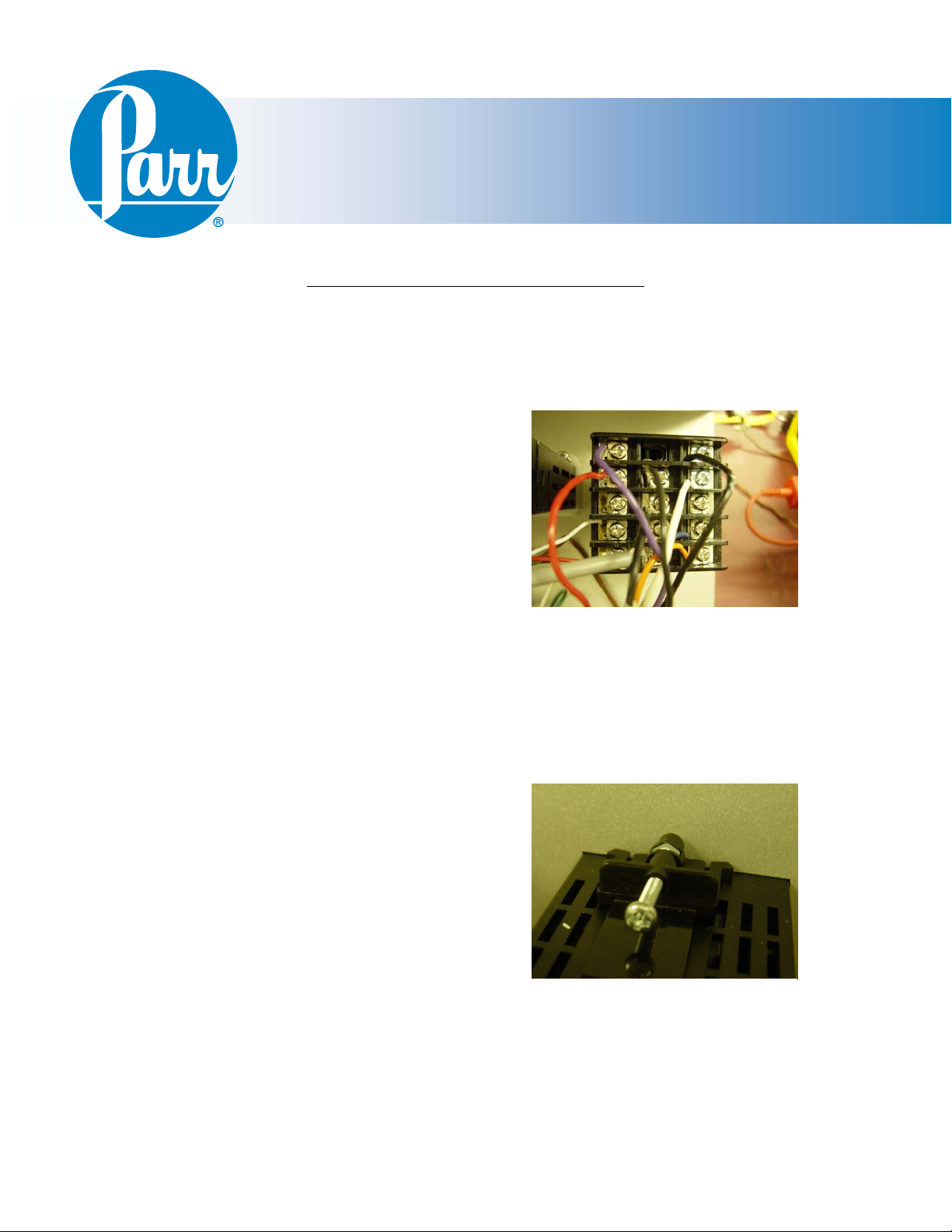
2. Make a note of where the wires are
installed on the existing primary
temperature meter. The pin numbers are
printed on the back of the meter itself.
They should match the Pin Out table on
the next page. Using tape to designate
each wire, record the pin number each
wire is attached to.
3. Using a Phillips screwdriver, remove the
wires from the back of the primary
temperature meter.
4. Using a Phillips screwdriver, remove the two screws on the top and bottom
mounting brackets. Pull the meter out.
5. Insert the new meter through the panel cutout, from outside in, making sure the
rubber gasket is on the outside of the
controller front panel. Slide the mounting
brackets onto the meter with the mounting
screws pointing towards the front panel.
Slide the mounting bracket forward until it
touches the controller panel. The clasps
on the mounting brackets should align
with the grooves on the meter. Gently
tighten the screws until the meter is held
into place.
6. Connect the free wires (disconnected in
step 3) to the new meter. Check the positions carefully and refer to the Pin Out
table.
a
r
r
r
i
i
r
y
T
e
m
p
e
r
a
m
a
r
y
T
e
m
m
a
r
i
y
T
Meter installation in 4838 Reactor Controller
e
m
p
p
e
e
t
r
a
t
r
a
t
f
o
r
f
o
r
e
t
e
r
i
n
4
8
3
e
t
e
r
i
n
e
t
e
Back of Primary Temperature Meter
Back of Primary Temperature Meter
r
i
n
8
4
8
3
4
8
3
8
8
n
C
o
n
C
o
C
o
n
t
r
o
l
l
e
r
o
o
l
l
e
r
l
l
e
r
t
r
t
r
- 1 -
Page 2
PTM Installation in a 4838
Pin Out Table:
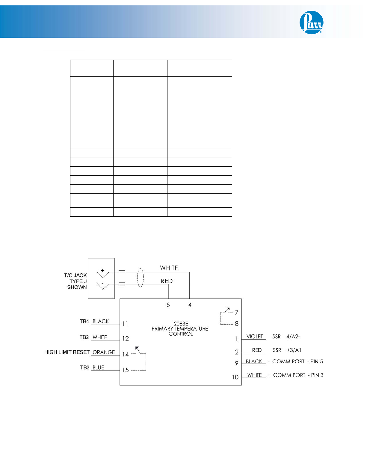
2083E
Meter
Pin 1 Purple SSR 4/A2Pin 2 Red SSR +3/A1
Pin 3 Red (RTD Only) Thermocouple Pin 4 White* Thermocouple +
Pin 5 Red** Thermocouple - 1G
Pin 6
Pin 7
Pin 8
Pin 9 Black COMM PORT - pin 5
Pin 10 White COMM PORT - pin 3
Pin 11 Black Terminal Block 4
Pin 12 White Terminal Block 2
Pin 13
Pin 14 Orange
Pin 15 Blue Terminal Block 3
Color: Attaches to:
High Limit Reset - pin
2
* White (Type - J), Yellow (Type - K), Blue (Type - T), Black (RTD)
** Red (Type - J, Type - K, Type - T), White (RTD)
Wiring Schematic
- 2 -
Page 3

PTM Installation in a 4838
Final Steps:
Close the controller and replace the two screws on the back plate. Plug the 4838 Controller back
in and turn it on. The display should show room temperature with the thermocouple connected.
It is useful to check that the settings on the display are set correctly. Check these against the
Factory Default Settings.
- 3 -
Page 4

PTM Installation in a 4838
Factory Default Settings for Primary Temperature Module
Keys command:
1. Press “SET” to select
2. Press return key move to next operation mode
3. Up/Down arrow keys to adjust value or select type
Press return key and release
Operation
Select type/value Comment
Mode
r-S Run Run/Stop
SP 0** Decimal point position
AL1H 375 Upper alarm setting
AL1L 0 Lower alarm setting
LoC OFF Lock mode(lock all keys or only up/down arrow
able to use)
Out1 - (read-only) Heater output %
Out2 - (read-only) Cooling output %
** If using a type-J or type-K thermocouple, SV = 0
If using an RTD, SV = 1
Press and hold down “SET” for 5-sec
Operation
Mode
InPt J** Input type
tPUn C Temperature unit
tP-H 800** Upper-limit range
tP-L 0 Lower-limit temperature range
CTRL PID Control mode (ON/OFF, MANUAL, PID and PID
S-HC H1C2 Output 1 is Heating and output 2 is Cooling
ALA1 6 Alarm operates when PV value is higher than AL1H
SALA OFF System alarm
CoSH ON Communication write function that able to use set
C-Sl ASCII Format type
C-no 1 Communication address
bPS 9600 Communication baud rate
Len 7 Data length setting
PrtY Even Parity bit setting
StoP 1 Stop bit setting
Select
type/value
Comment
PROG)
setting or PV value is lower than AL1L setting
point from software
** If using a type-J thermocouple, InPt = J, tP-H = 800
If using a type-K thermocouple, InPt = K, tP-H = 800
If using an RTD, InPt = Pt, tP-H = 600
- 4 -
Page 5

PTM Installation in a 4838
Factory Default Settings for Primary Temperature Module
Press “SET” and release
Operation
Mode
At OFF Auto Tuning ON/OFF
PID0 0 The 0th PID Parameter
SV 0 The 0th SV
P0 11.8 Proportional control
I0 375 Integral control
D0 93 Derivative control
IoF0 0 Integral value offset
HtPd 5 Heat cycle control
HcPd 5 Cool cycle control
CoEF 10 1 & 2 value output group during dual loop output
dEAd 0 Dead band
tPoF 0 Inaccuracy adjustment
Select
type/value
Comment
control
- 5 -
Page 6

PTM Installation in a 4838
This page left blank intentionally.
- 6 -
Page 7

PTM Installation in a 4838
This page left blank intentionally.
- 7 -
Page 8

Parr Instrument Company
211 53rd Street • Moline, Illinois 61265 USA
1-309-762-7716 • 1-800-872-7720 • Fax: 1-309-762-9453
E-mail: parr@parrinst.com • http://www.parrinst.com
Revision 07/08/09
 Loading...