

Page 1
No. 562M
I
n
s
t
a
l
l
a
t
i
o
n
I
n
s
t
r
u
c
t
i
o
n
s
f
o
r
I
n
s
t
a
l
l
a
t
i
o
n
I
n
s
t
r
u
c
t
i
o
e
e
e
c
a
a
a
n
t
i
o
n
c
t
o
c
t
o
c
t
o
I
n
s
t
a
l
l
a
t
i
o
n
I
n
s
t
r
u
(
P
D
M
)
i
n
(
P
D
M
(
P
D
M
Meter Installation in 4838 Reactor Controller
1. Unplug the power cord of the 4838 controller. Remove the (2) screws located on the top
corners of the rear panel on the controller. Gently lift the cover, which is hinged at the
bottom, forward taking care not to apply tension on any wiring internally.
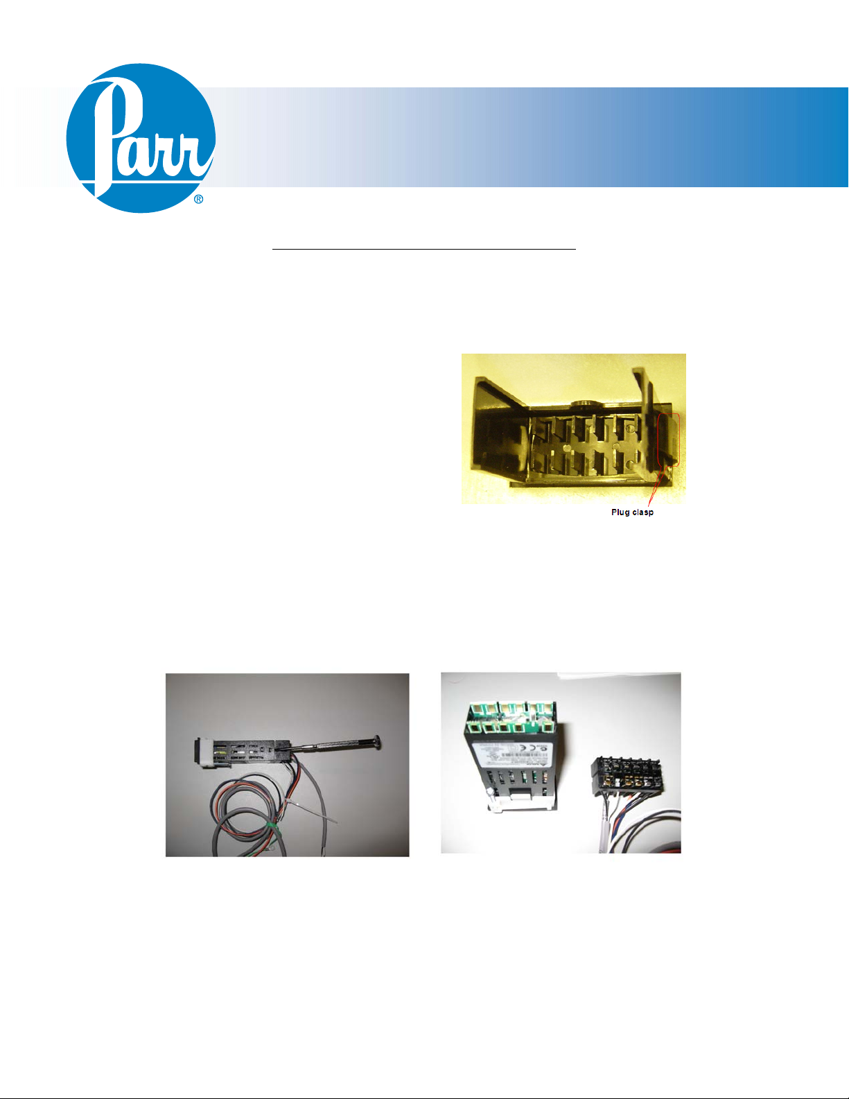
2. If applicable, remove and discard the black
hole plug on the sloped front panel. This can
be done by pinching the clasps on the back of
the plug from the inside of the front plate.
3. Insert the controller through the panel cutout,
from outside in, making sure the rubber gasket
is on the outside of the controller front panel.
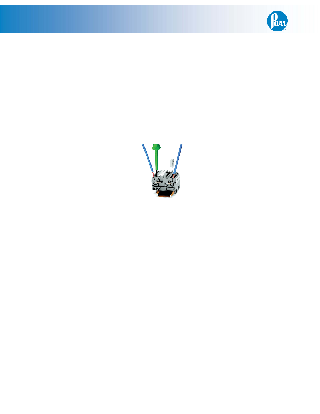
(If wires are preinstalled, remove the terminal connector by releasing the tabs on the sides of
the 2082E meter and gently pulling the terminal connector off. Reference photos below.)
Slide the white mounting bracket onto the 2082E with the mounting screws pointing towards
the front panel. Slide the mounting bracket forward until it touches the controller panel. The
clasps on the mounting bracket should align with the groves on the 2082E. Gently tighten
the screws until the 2082E is held into place. (If removed, reattach the terminal connector.)
)
i
n
)
i
n
8
4
4
4
8
8
8
3
3
3
8
8
R
R
R
s
s
P
f
o
r
P
f
o
r
P
r
C
o
n
r
C
o
n
r
C
o
n
s
r
t
t
t
u
e
r
e
r
e
r
o
r
o
r
o
s
s
l
s
l
r
e
D
i
s
p
l
a
y
M
o
d
u
l
e
s
u
r
e
D
i
s
p
l
a
y
M
o
s
u
r
e
D
i
s
p
l
a
y
l
e
r
l
e
r
l
l
e
r
M
o
d
d
u
u
l
e
l
e
Terminal Connector Removal
Page 2
PDM Installation
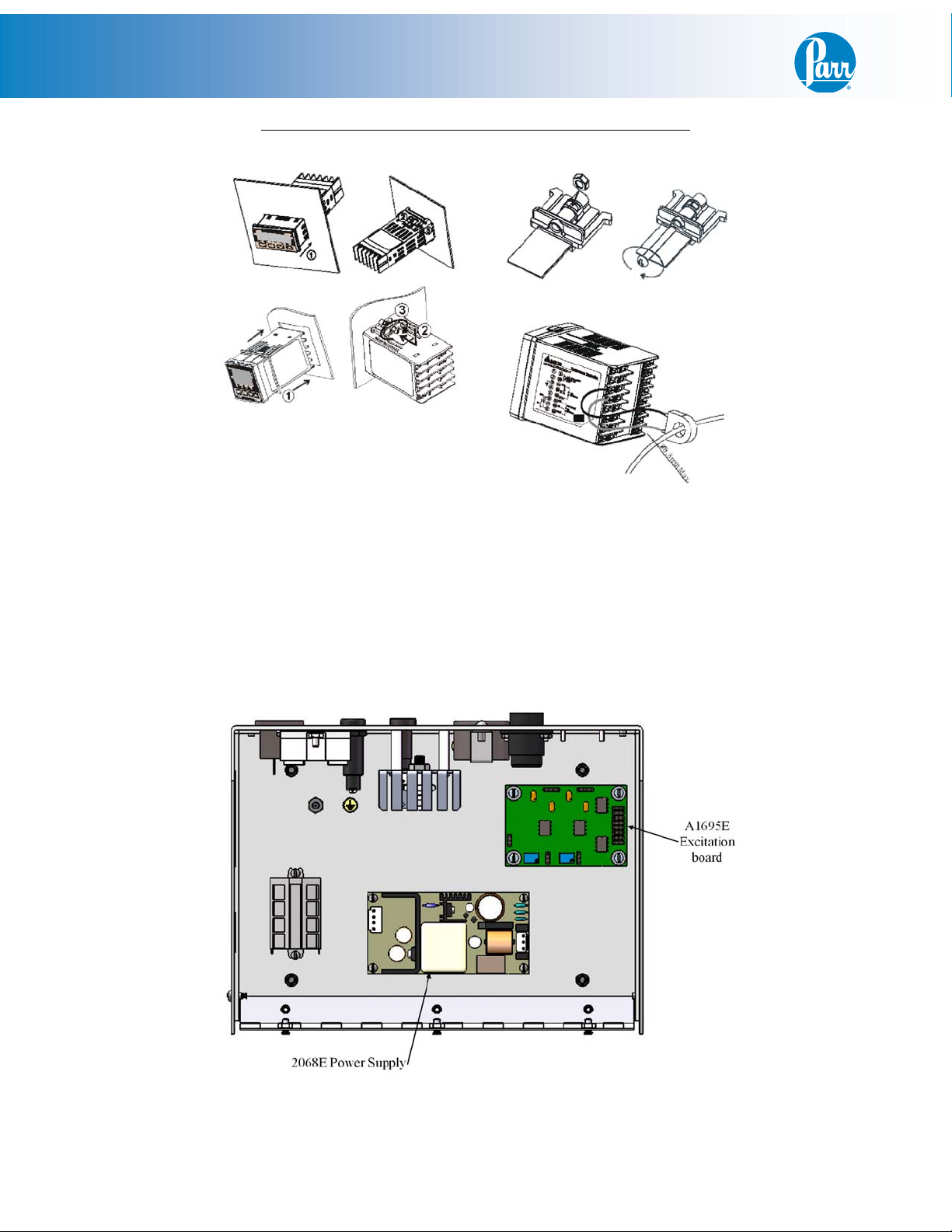
4. Mount the 2068E power supply, orient as shown, using the (4) SA1140RD06 4-40 screws
supplied.
5. Mount the A1695E Excitation Board, orient as shown, using the (4) SA1332RD06 6-32
screws and (4) 2807HC spacers.
Meter installation in 4838 Reactor Controller (continued)
Meter Installation Diagram
4838 Inside View
- 2 -
Page 3
PDM Installation
1. If applicable, remove the black hole plug on the back of the controller, labeled PRESSURE
INPUT. This can be done by pinching the clasps on the back of the plug from the inside of
the back panel.
2. Insert the 9-pin receptacle (825E), on the A2104E, into the pressure input hole from the
inside out. Slide the Ring Terminal, on the A2104E green wire, onto one of the mounting
studs. Mount the receptacle using the (2) #4 keps nuts provided.
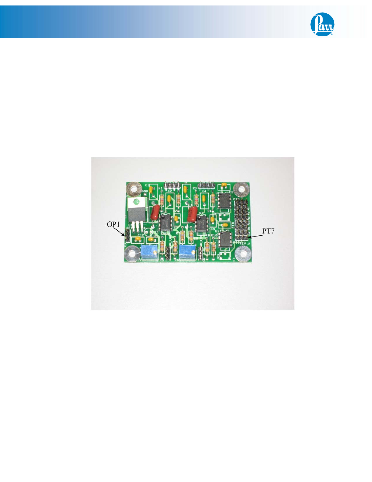
3. Locate the A1695E Excitation Board as shown.
Wiring installation in the 4838 Reactor Controller
4. Attach the 3-pin edge connector from the A2104E to “PT7” with the black wire closest to the
edge of the A1695E excitation board.
- 3 -
Page 4
PDM Installation
Wiring installation in the 4838 Reactor Controller (continued)
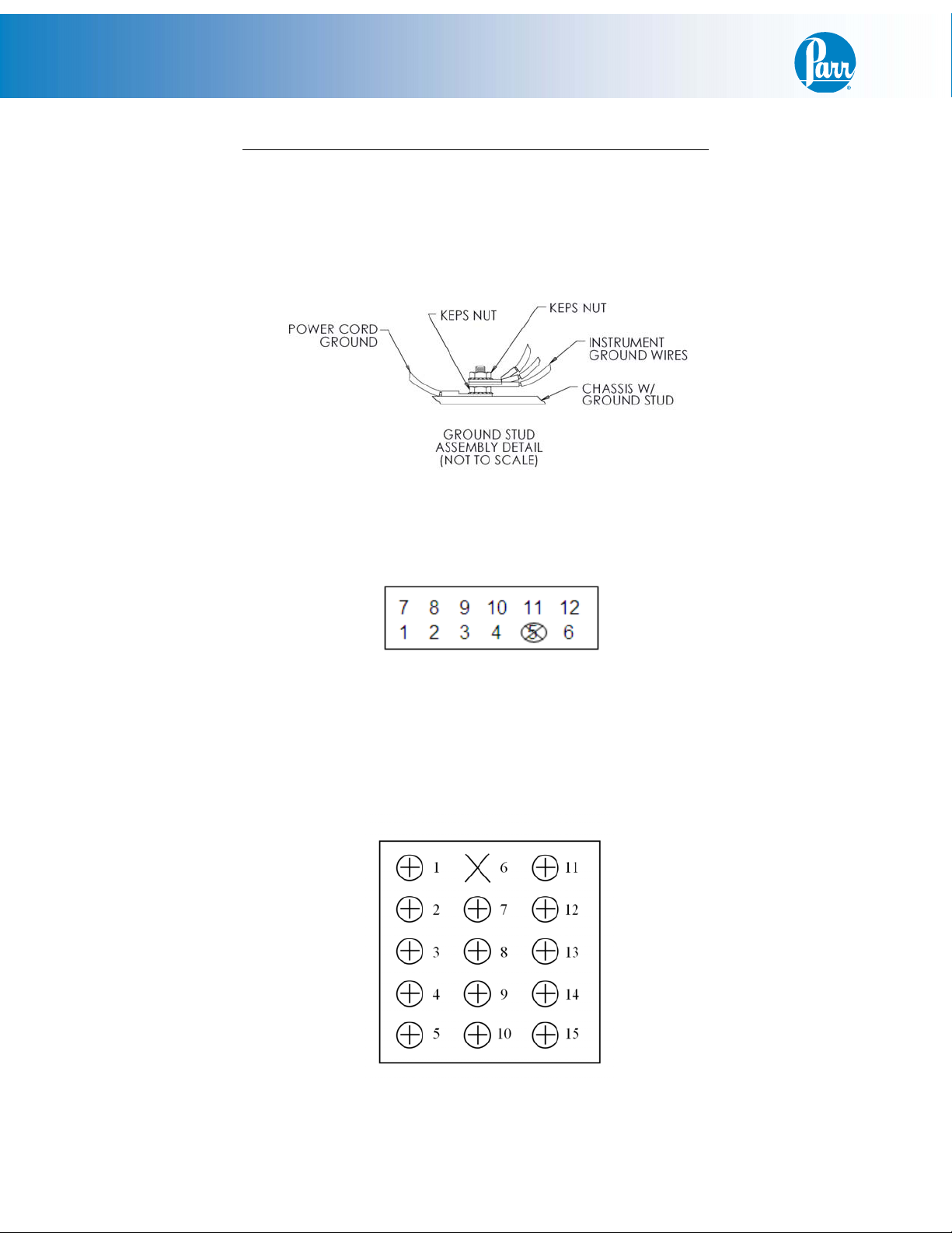
5. Find the loose 3-pin edge connector, with yellow and white wires, and attach to “OP1”.
Attach the other end, with yellow white and green wires, to the 2068E Power Supply. (This
may already be connected for your convenience.) The green wire #4 will attach to the
ground stud by removing the top #8 keps nut as shown (Reference Instrument Ground
Wires).
6. Attach the stripped white wire #13, from the A2104E harness, to terminal #4 on the 2082E
pressure meter. Attach the stripped black wire #12 to terminal #6 on the 2082E pressure
meter. (This may already be connected for your convenience.)
2082E Terminal Pin-out
7. Find the black #6 and white #7, a 2-wire cable with both ends stripped, and attach one end
to the 2082E meter. (This may already be connected for your convenience.) White wire #7
to terminal 11 and black wire #6 to terminal 12. Take care not to apply too much torque
which may eventually cause the wire to break. The other end attaches to the 2083E primary
temperature controller. White wire #6 to terminal #10 and black wire #7 to terminal #9.
This will be in tandem with the existing wires on the 2083E.
2083E Terminal Pin-out
- 4 -
Page 5
PDM Installation
8. Find the orange wire #8, with both ends stripped, and attach one end to terminal #8 on the
2082E meter. (This may already be connected for your convenience.) Attach the other end in
tandem with the existing wire at terminal #14 of the 2083E primary temperature controller.
9. Find the blue wire #9, with both ends stripped, and attach one end to terminal #7 on the
2082E meter. (This may already be connected for your convenience.) Attach the other end to
terminal block position #3 (Neutral) located on the bottom inside of the controller.
Note: The terminal block position can be opened up using a small flat head screw driver to
release the tension from the spring inside the block so you can press the wire against the
spring.
Wiring installation in 4838 Reactor Controller (continued)
10. Find the black wire#10, with both ends stripped, and attach one end to terminal #1 on the
2082E meter. (This may already be connected for your convenience.) Attach the other end to
terminal block position #4 (Line).
11. Find the white wire #11, with both ends stripped, and attach one end to terminal #2 on the
2082E meter. (This may already be connected for your convenience.) Attach the other end to
terminal block position #3 (Neutral).
12. Find the black wire #2 and white wire #1, a 2-wire harness with 3-position connector, and
attach the 3-position connector to the power supply. (This may already be connected for
your convenience.) The stripped end of white wire #1 goes to terminal block position #3
(Neutral) located on the bottom inside of the controller. The stripped end of the black wire
#2 goes to terminal block position #1 (line).
- 5 -
Page 6

PDM Installation
Final Steps
Close the controller and replace the two screws on the back panel. Plug the 4838 controller back in,
and turn it on. The PDM display should read zero when the motor is not turning.
It is useful to check that the settings on the display are set correctly. Check these against the defaults
listed in the back of these instructions.
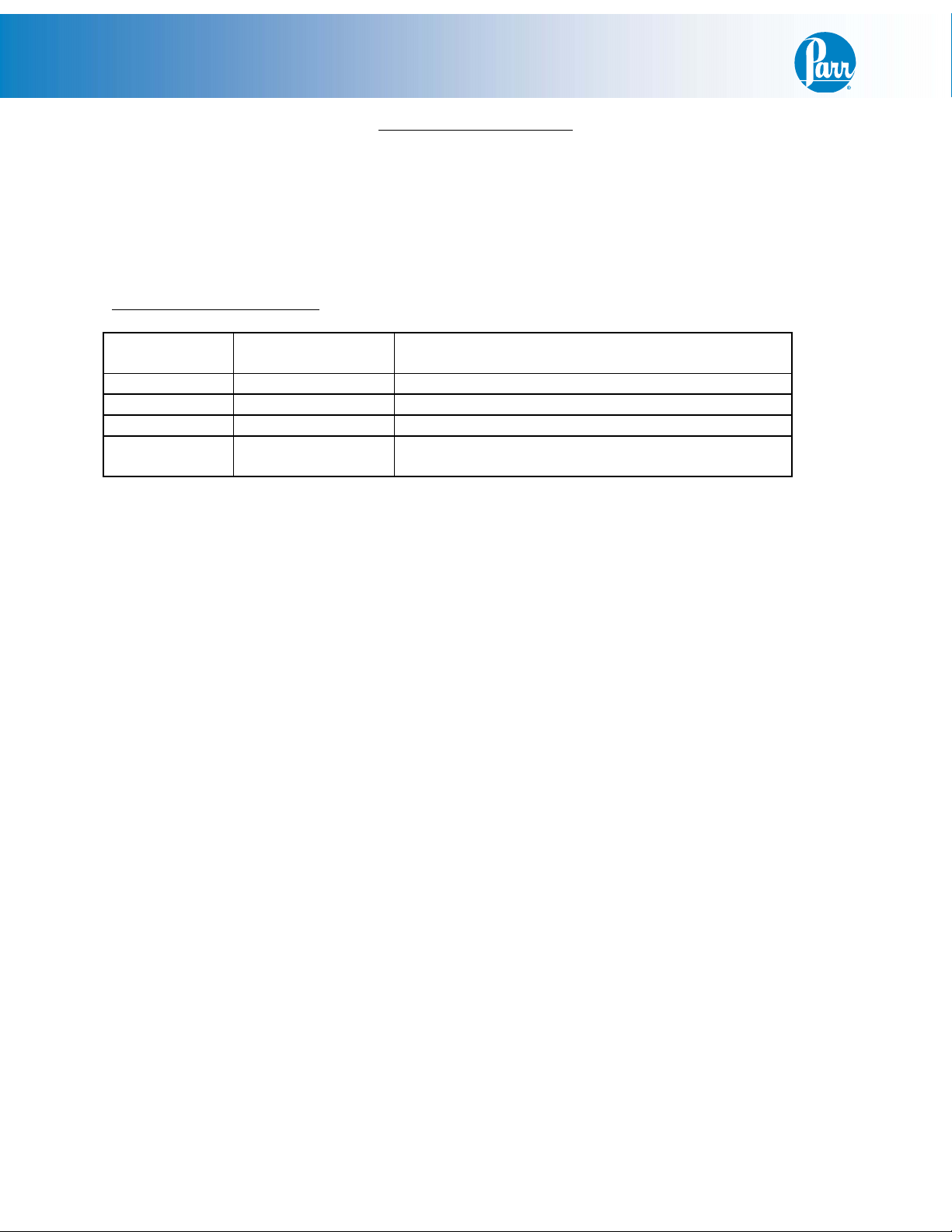
Meter Pin Outs
2082E Color: Attaches to:
Pin 1 Black Terminal Block 4
Pin 2 White Terminal Block 3
Pin 3
Pin 4 White A2104E Harness Pin 1
Pin 5
Pin 6 Black A2104E Harness Pin 2
Pin 7 Orange 2083E Primary Temp
Controller Terminal 14
Pin 8 Blue Terminal Block 3
Pin 9
Pin 10
Pin 11 White 2083E Primary Temp
Controller Terminal 10
Pin 12 Black 2083E Primary Temp
Controller Terminal 9
2083E Color: Attaches to:
Pin 1 Violet 1119E SSR Terminal 4
Pin 2 Red 1119E SSR Terminal 3
Pin 3 T/C Cable RTD only T/C Jack (-) RTD
Pin 4 T/C Cable T/C Jack (+)
Pin 5 T/C Cable T/C Jack (-)
Pin 6
Pin 7
Pin 8
Pin 9 Black Comm Receptacle Pin 5
Pin 10 White Comm Receptacle Pin 3
Pin 11 Black Terminal Block 4
Pin 12 White Terminal Block 2
Pin 13
Pin 14 Orange 542E High Limit Switch
Position 2
Pin 15 Blue Terminal Block 3
- 6 -
Page 7
PDM Installation
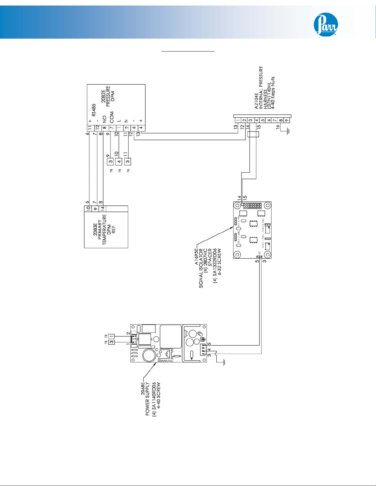
Wiring Schematic
- 7 -
Page 8
PDM Installation
Pressure Module Defaults
Keys command:
1. Press “SET” to select
2. Press return key move to next operation mode
3. Up/Down arrow keys to adjust value or select type
Main Screen: SP = 80% of span
Press return key and release
Operation
Select type/value Comment
Mode
r-S Run Run/Stop
SP to be determined** Decimal point position
AL1H 0 Upper-limit alarm 1
LoC OFF Lock mode(lock all keys or only up/down arrow
able to use)
** If units are psi, SP = 0
If units are Bar, SP = 1
If units are MPa, SP = 2
- 8 -
Page 9

PDM Installation
Pressure Module Defaults (continued)
Press and hold down “SET” for 5-sec
Operation
Select type/value Comment
Mode
InPt V5 Input type (V5 = 0-5V, V10 = 0-10V,
nA0 = 0-20mA, nA4 = 4-20mA, nV =0-
50mV)
tP-H determined by transducer** Upper-limit pressure range
tP-L 0 Lower-limit temperature range
CTRL ON/OFF Control mode (ON/OFF, MANUAL,
PID and PIDPROG)
S-HC Heat Heat/Cool control
ALA1 2 Alarm operates when PV value is higher
than SV Value + ALH setting
SALA OFF System alarm
CoSH ON Communication write function that able
to use set point from software
C-Sl ASCII Format type
C-no 2 Communication address
bPS 9600 Communication baud rate
Len 7 Data length setting
PrtY Even Parity bit setting
StoP 1 Stop bit setting
** Set according to the following:
Transducer range - psi
tP-H for psi tP-H for Bar tP-H for MPa
200 200 13.79 1.38
500 500 34.47 3.45
1000 1000 68.95 6.89
2000 2000 137.9 13.79
3000 3000 206.8 20.68
5000 5000 344.7 34.47
Press “SET” and release
Operation
Select type/value Comment
Mode
HtS 0 Heating hysteresis setting
tPoF 0 Temperature correction
- 9 -
Page 10

PDM Installation
This page left blank intentionally.
- 10 -
Page 11

PDM Installation
This page left blank intentionally.
- 11 -
Page 12

Parr Instrument Company
211 53rd Street • Moline, Illinois 61265 USA
1-309-762-7716 • 1-800-872-7720 • Fax: 1-309-762-9453
E-mail: parr@parrinst.com • http://www.parrinst.com
Revision 05/15/09
 Loading...