

Panasonic TY-TP65P10S User Manual
Operating Instructions
Touch Panel
Model No.
TY-TP65P10S
Before connecting, operating or adjusting this product, please read these instructions completely.
Please keep this manual for future reference.
English
TQZH948
Accessories
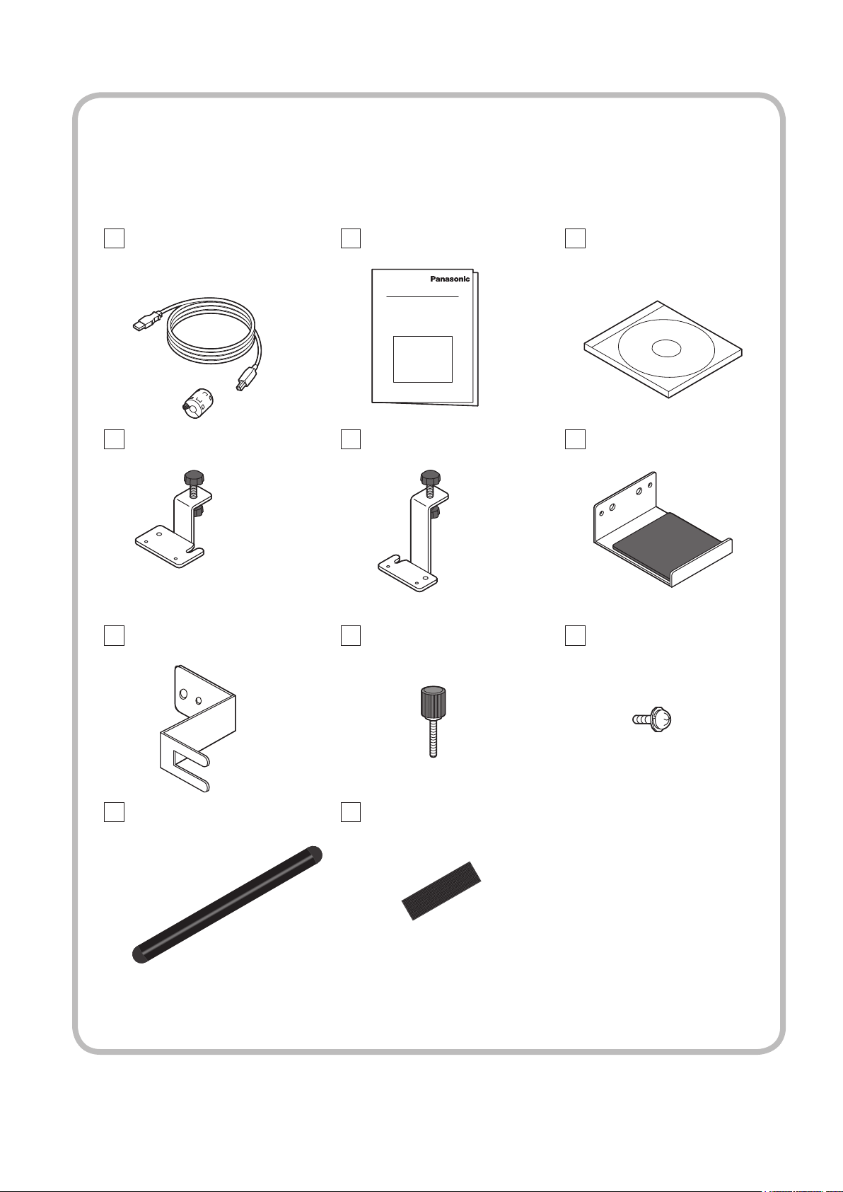
Before assembling, attaching and connecting anything, check all accessories have been included in the
product package. Quantities are indicated in ( ).
USB cable 3 m (1)
Ferrite core (1)
Mounting bracket A (2)
USB cable anchor (1)
Operating Instructions (8)
• Japanese
• English
• German
• French
• Italian
• Spanish
• Russian
• Ukrainian
Mounting bracket B (2) Vertical mounting
Mounting screw A (9) Mounting screw B (12)
CD-ROM (1)
Driver software
bracket (2)
22
Touch pen (1)
(p. 7)
• Illustrations and screens appearing in these operating instructions are conceptual views and may differ
from the actual equipment.
• Windows is a registered trademark of Microsoft Corporation in the USA and other countries. (The official name of
Windows is Microsoft® Windows® Operating System.)
• The names of other companies and products appearing in this publication are the trademarks, registered
trademarks or products names of their respective owners.
Velcro strip (2)
(p. 7)

Contents
READ FIRST!
■
Precautions with regard to setting up ............... 4
■
Maintenance ......................................................... 6
■
Names of Parts ..................................................... 7
Installation & Setup
■
Touch Panel Assembly ........................................ 8
■
Mounting Touch Panel ........................................ 9
■
Setup Procedure. ............................................... 13
■
Driver Software Installation .............................. 14
■
Connections and Plug-Ins ................................ 16
■
Driver Software Uninstallation ......................... 19
READ FIRST!
Installation & Setup
Operation
■
Touch Panel Setup ............................................. 20
How to Use the Driver Software ............................................. 20
Explanation of Setup Panel Items .......................................... 21
Advanced setting ................................................................... 25
Calibration .............................................................................. 27
Touch setting ..........................................................................
Area Button Setup .................................................................. 32
Multiple Monitor Setup ........................................................... 35
Setting Sensor Position .......................................................... 39
Troubleshooting
■
Before Calling for Service ................................. 40
■
Error Messages .................................................. 42
USB Bandwidth Error ............................................................. 42
■
Specifications .................................................... 44
Operation
29
Troubleshooting
■
External Dimensions ......................................... 45
3

Precautions with regard to setting up
WARNING
Do not allow the equipment to get wet.
• If liquid splashes onto the equipment, wipe off with a dry cloth. In the unlikely event that liquid gets inside the
product, unplug the USB cable and contact your dealer. Using the product with liquid still inside may cause a fire
or electric shock.
Do not disassemble or modify the equipment.
• Doing so may cause a fire or electric shock.
Do not touch the edge of the infrared transmissive part on the touch panel.
• The edge of the infrared transmissive part is sharp; you may be injured if you touch it.
Stop using the equipment if anything abnormal occurs.
• In the unlikely event that something abnormal occurs (like the equipment emitting smoke or an odor), unplug
the USB cable and contact your dealer. Using the product in this condition may cause a fire, electric shock or
malfunction.
Installation work should only be carried out by a qualified technician.
• If the bracket is installed incorrectly, the display may fall down and personal injury may result.
CAUTION
When unplugging the USB cable, be sure to grip the connector.
• Unplugging by pulling on the cord may cause cord damage, a fire or electric shock.
Do not place the equipment in a location subject to high humidity or excessive dust.
• Doing so may cause a fire, electric shock or malfunction.
Do not place the equipment in a location where it may be exposed to smoke or steam, or near a stove,
kitchen sink or humidifier.
Do not place the equipment in a location where it may be exposed to direct sunlight.
• Internal temperature may rise and cause a fire.
• This equipment has an optic touch panel that uses infrared rays. Direct sunlight contains infrared rays, and this
may interfere with touch panel operation.
Before moving the equipment, unplug the USB cable.
• Failure to do so may damage the cord, and cause a fire or electric shock. Failure to do so also may result in fall
of the equipment and cause injury.
If the equipment will not be used for a long time, unplug the USB cable.
• To ensure safety, be sure to unplug the USB cable from the socket.
Do not place the equipment on an unstable surface, or in a location subject to heavy vibration.
• If the equipment tips over or falls, it may cause injury or malfunction. In the unlikely event that the equipment is
damaged, unplug the USB cable and contact your dealer. Using the equipment in this condition may cause a
fire, electric shock or malfunction.
Do not lie the touch panel unit face down or place a plasma display on top of it.
• The weight of the plasma display will be applied to the touch panel unit and may cause malfunction.
Do not move the equipment after attaching the touch panel unit to the plasma display.
• The weight of the plasma display will be applied to the touch panel unit and may cause malfunction.
Do not place the equipment in a hot or cold location.
• Using the equipment in an extremely hot or cold location may cause malfunction.
Do not use fluids like benzene, thinner or alcohol to clean the equipment.
• Doing so may cause deformation or ruin the finish by discoloration.
To prevent incorrect operation, do not use other equipment utilizing infrared rays near this equipment.
Ensure that all the screws are securely tightened when assembling the touch panel.
• If the screws are not securely fastened, the touch panel may fall off and be damaged, which may cause injury.
Two people are required to install and remove the display.
• If two people are not present, the display may be dropped, and personal injury may result.
Do not use any displays other than those given in the catalogue.
• Otherwise the unit may be dropped and become damaged, and personal injury may result.
4

Precautions with regard to setting up
Cautions when in use
Always keep the touch panel clean.
• This optical touch panel utilizes infrared rays and may operate incorrectly if the infrared transmissive part
becomes soiled. Use a soft dry cloth to clean the infrared transmissive part once every day.
Use a power supply within the rated voltage range.
• Be sure that the power supply used conforms to the rated voltage. Use with a power supply exceeding the rating
may cause incorrect operation or malfunction.
Keep the equipment away from locations subject to heavy electrical noise.
• Avoid use near equipment that produces excessive electrical noise. Noise may enter the equipment via the
power supply or interface and cause incorrect operation.
Do not touch the infrared transmissive area until starting OS.
• After turning on the PC, be sure not to touch the infrared transmissive area on the screen until the PC
has completed the starting of its OS. If this is not observed, device errors may be detected by the PC and
subsequently it will not operate correctly. Should this occur, please restart the PC.
• When connecting or disconnecting the USB cable, be careful not to touch the infrared transmissive area.
Keep foreign matter out of the equipment.
• Do not allow metal objects or combustible material to fall or be inserted into the equipment through openings.
Using the equipment with foreign matter inside may cause problems such as electric shock or malfunction.
Keep away from water.
• If water or any other liquid gets inside the equipment it may cause fire, electric shock or malfunction. Do
not place containers that hold liquid (flower vases, fish bowls, cosmetics, chemicals or water) on top of the
equipment.
Do not place heavy objects on the equipment.
• The touch panel is made of sheet metal. It is dangerous to place heavy objects on top of it.
Use only the touch pen included with this touch panel. Operation is not guaranteed with other products.
READ FIRST!
Setup location
Before setting up the touch panel, select an optimal location by following the precautions below.
Places where the equipment should not be setup include:
• Locations subject to extremely high or low temperature
• Locations subject to high humidity
• Locations exposed to direct sunlight, and locations near powerful light sources
(This is an optical touch panel, so you should be particularly careful of this point)
• Locations subject to excessive dust
• Locations exposed to shock or vibration
• Locations near emissions of chemicals or steam, or locations where contact may be made with chemicals
• Locations near sources of electrical noise (generators, air conditioners etc.)
5

Maintenance
Maintenance
* Be sure to unplug the USB cable before cleaning the equipment.
Clean the inside of the equipment once a year.
• The equipment is of semi-sealed construction, so dust may eventually accumulate inside. This may cause poor
operation due to a reduction in the level of infrared light available for touch detection. Cleaning frequency will
vary depending on the setup location; if in doubt consult the dealer from whom you purchased the equipment.
• Be careful not to touch the infrared transmissive area on the screen of the plasma display and rub the screen
with excessive force.
Cleaning of the infrared transmissive area.
• Once a day, use a soft cloth to wipe off any soiling or debris on the infrared transmissive area. Failure to do so
will cause a malfunction, but on such an occurrence you can restore normal function simply by gently wiping the
soiling off. If soiling is severe, wet a cloth in neutral detergent diluted by 100 times of water, wring well, wipe off
the soiled part, and then wipe well with a dry cloth.
• Be aware that if you apply volatile fluids such as thinner, benzene or insecticide, or allow long-term contact with
products containing materials such as rubber or vinyl, the surface of the equipment may discolor or deform. Also,
be careful of wiping with chemically-treated cloths, because such action may cause similar to happen.
If something abnormal happens
If the equipment starts to smoke or emit a strange odor.
• It is extremely dangerous to continue using the equipment in such a malfunctioning state.
Immediately unplug the USB cable from the computer, and request the dealer from which you purchased the
equipment for repair.
6
�
�
Names of Parts
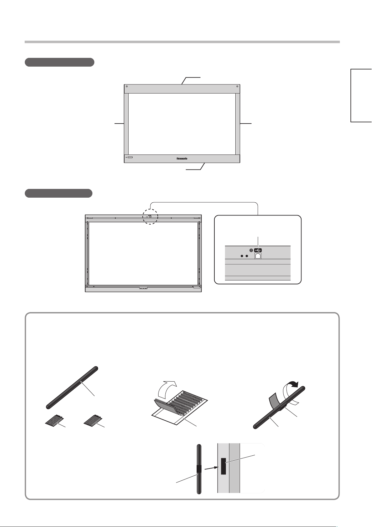
Touch Panel (Front)
Left unit Right unit
Touch Panel (Rear)
READ FIRST!
Top unit
Bottom unit
■
Attaching the Velcro strip to the touch pen
Prepare the below included accessories
•
Touch pen
Velcro strip
(with white backing)
Peel off the backing from
the Velcro strip.
USB port
Wrap the Velcro strip around
the center of the touch pen.
Touch Pen
•
Attach the Velcro strip to the touch panel
so as to hold the touch pen.
Touch pen
Velcro strip
(with yellow backing)
7
Touch Panel Assembly
Lay the top, side and bottom units on the packaging cushions.
1
Arrange the packaging cushions (6) on the
floor so that their arrows point in the same
direction.
Set the top, side and bottom units inside the
grooves of the packaging cushions.
(The arrows on the right and the left units
should point toward the top unit.)
Caution
Touch panel projections can be damaged if
exposed, therefore lay panel parts in the packaging
cushions to assemble.
Packaging
cushions
Top unit
Bottom unit
Lock the side units to the top unit.
2
Align the projections on the panel
support plate of the top unit with the
holes on the left and right units.
Lock the left and right units to the top
unit with mounting screws B (4).
Notes on Assembly
• The installation hole of mounting screw B differs for the left and right units.
• If the parts do not fit together properly, switch the left and right units and try again.
Mounting
screws B
Panel support plate
Arrow
Arrow
Top unit
8
Lock the bottom unit to the side units.
3
Align the projections on the panel support
plate of the bottom unit with the holes on
the left and right units.
Lock the left and right units to the bottom
unit with mounting screws B (4).
Panel support plate
Mounting
screws B
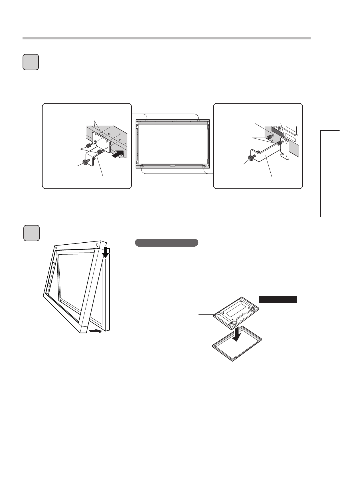
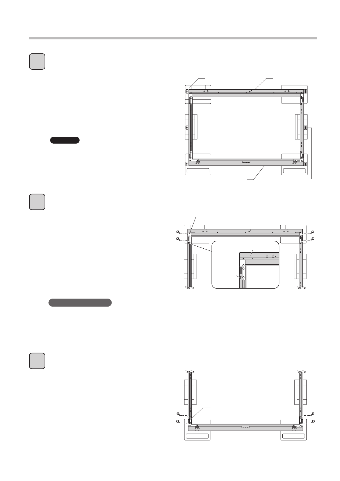
Mounting Touch Panel (in Horizontal Posture)
Attach mounting brackets to the touch panel.
1
Fit the protrusion located above the round hole on mounting bracket A into the hole of the top unit and
then tighten mounting screw A by hand.
As shown in the diagram, tighten mounting screw A by hand to hold mounting bracket B temporarily
after fitting the protrusion located above the round hole on the mounting bracket B into the hole of the
bottom unit. Screw mounting screw A into the hole of the bottom unit half way.
Protrusions
Mounting
screws A
Screw
Mounting bracket A
Attach the touch panel to the front of the plasma display.
2
Notes on Assembly
• Work in two or more to attach the touch panel to the plasma
display. If the touch panel is dropped, injuries may occur.
• Because it can damage the infrared sensor of the touch panel, do
not lay the touch panel down and attach the plasma display to it
from above. Service for damage caused by installation in this way
is subject to billing.
Screw in
halfway
Mounting
screws A
Screw
Mounting bracket B
Protrusion
Installation & Setup
Plasma display
Touch panel
INCORRECT
Floor
9
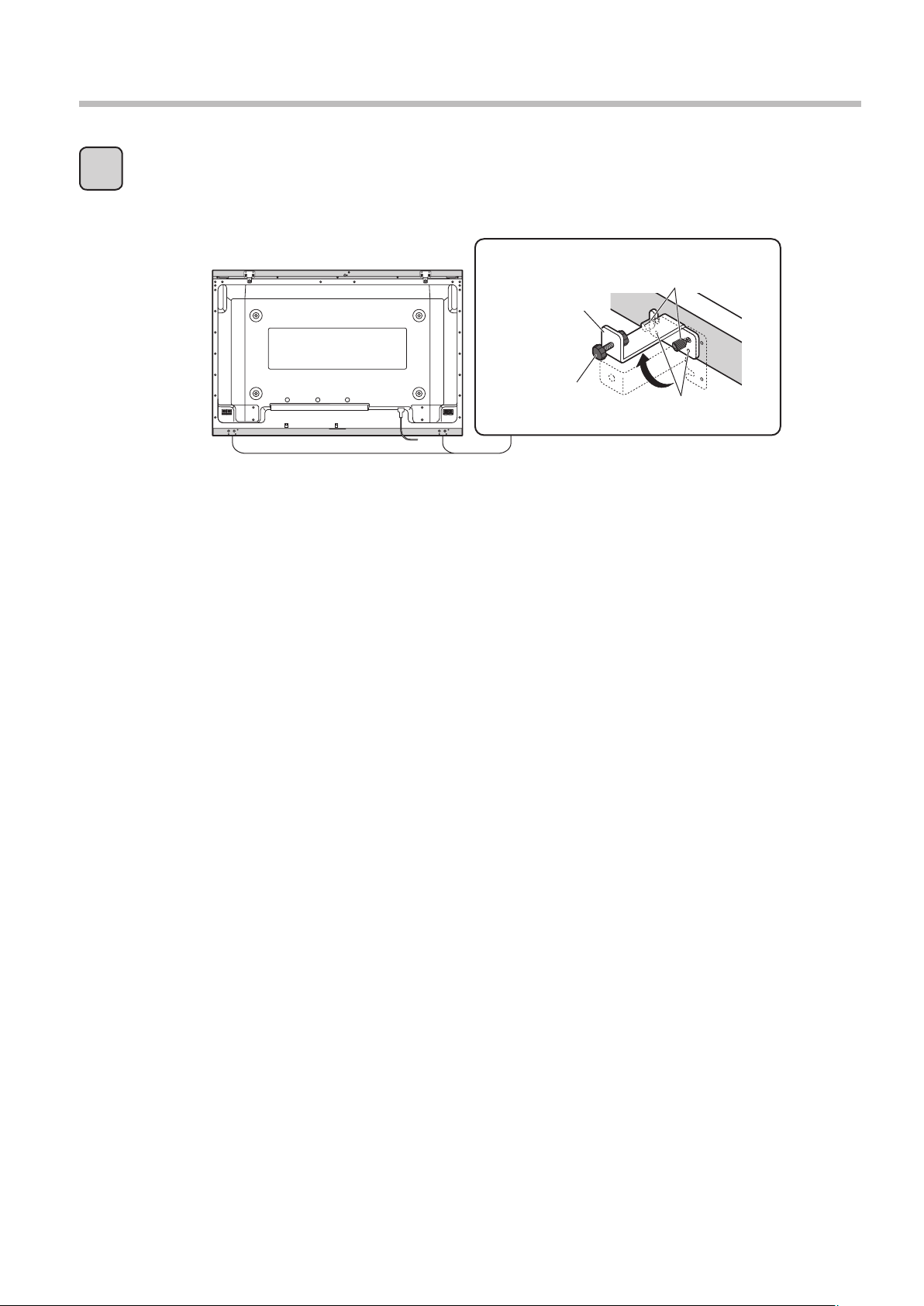
Mounting Touch Panel (in Horizontal Posture)
Lock the touch panel to the plasma display.
3
Loosen mounting screw A on mounting bracket B (temporarily held) and rotate the bracket 90
degrees, as shown in the diagram, fit the protrusion located above the round hole on mounting bracket
B into the hole of the bottom unit. Tighten both mounting screws A by hand.
Mounting screws A
Mounting
bracket B
Screw
Protrusions
Turn the screws on mounting brackets A and B until the gap between the touch panel and plasma
display is closed, then make 2 more full turns to lock in place.
10
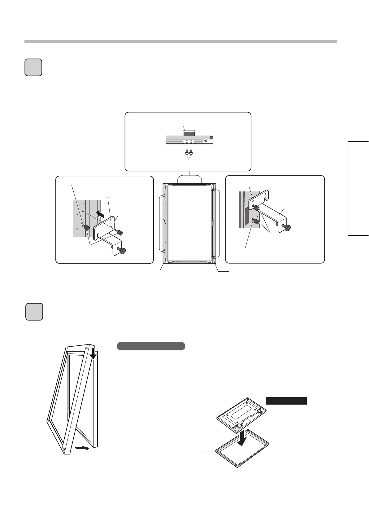
Mounting Touch Panel (in Vertical Posture)
Attach mounting brackets to the touch panel.
1
Fit the protrusions on the vertical mounting brackets into the holes of the unit and affix the brackets
with mounting screws B.
As shown in the diagrams, tighten mounting screws A by hand to temporarily hold the brackets A and B
after fitting the protrusions located above the round holes on both brackets into the holes of the top and
bottom units. Screw mounting screws A into the top and bottom units half way.
Screw in halfway
Protrusion
Mounting
screws A
Vertical mounting brackets
Mounting
bracket A
Top unit
Mounting screws B
Protrusion
Mounting screws A
Screw in halfway
Bottom unit
Installation & Setup
Mounting
bracket B
Attach the touch panel to the front of the plasma display.
2
To attach the touch panel to the plasma display, align the top and bottom edges of the touch panel
with the top and bottom edges of the plasma display. Once attached, adjust the fit so that the left and
right black frames on the front of the plasma display are the same width.
Notes on Assembly
• Work in twos or more to attach the touch panel to the plasma display. If the
touch panel is dropped, injuries may occur.
• Because it can damage the infrared sensor of the touch panel, do not lay the
touch panel down and attach the plasma display to it from above. Service for
damage caused by installation in this way is subject to billing.
Plasma display
Touch panel
INCORRECT
Floor
11
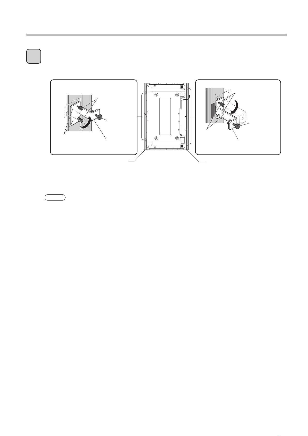
Mounting Touch Panel (in Vertical Posture)
Lock the touch panel to the plasma display.
3
Loosen mounting screws A on mounting brackets A and B (temporarily held) and rotate the brackets 90
degrees, as shown in the diagrams, fit the protrusions located above the round holes on the brackets
into the holes of the top and bottom units. Then tighten both mounting screws A by hand.
Mounting
screws A
Screw
Protrusions
Turn the screws on mounting brackets A and B until the gap between the touch panel and plasma
display is closed, then make 2 more full turns to lock in place.
Note
If you are using the touch panel in vertical position, set the sensor position of the touch panel as “Vertical”.
(p. 39)
Mounting
bracket A
Top unit
Mounting
screws A
Bottom unit
Protrusions
Screw
Mounting
bracket B
12
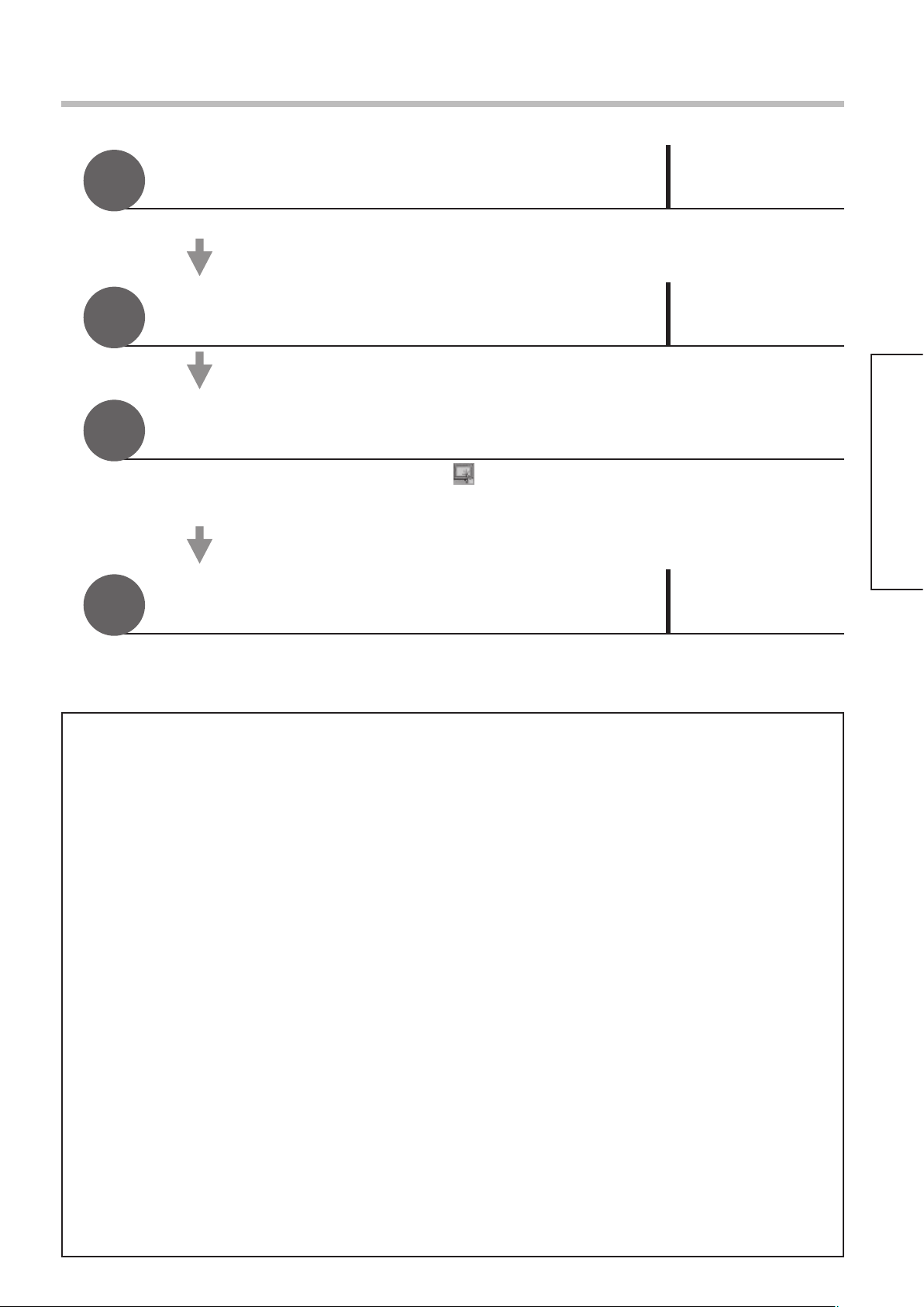
Setup Procedure
1
2
3
4
Install the Driver Software
Do not connect the USB cable yet.
Connect the touch panel and computer
P. 14
P. 16
Restart your computer
• After restarting your computer, check appears in the task tray.
• If the icon does not appear, if it appears with an X over it or if an error message is displayed,
see “Before Calling for Service” (p. 40) and “Error Messages”. (p. 42)
Calibrate the touch panel
P. 27
Installation & Setup
This completes the basic setup.
■ Driver Software Operating Environment
The Driver software is supported by both the Japanese and English versions of Windows 2000 (SP4 or
later), Windows XP (SP1 or later) and Windows Vista (32-bit only).
* Windows is a registered trademark of Microsoft Corporation in the USA and other countries.
The following environment is required to correctly install and start up the Driver software.
<Windows 2000 or Windows XP>
• CPU … Pentium III or later (2 GHz or faster Celeron or Pentium 4 recommended)
• Memory … 512 Mbytes or more
• HDD … 30 Mbytes or more available area
• Compatible with USB 1.1/2.0 interface
■
Driver Software Restrictions
• The mouse emulation feature cannot be used on the login window that appears at Windows startup, when
restoring from the suspended state or when the screen saver is unlocked. The mouse emulation feature is
activated after you log in.
• There is no remote wakeup feature that activates the screen from the suspended state by touching the
touch panel.
• If your system does not meet the requirements above or the applications use up too much memory, the
response of the touch panel may slow down.
• Only Windows is supported. (Operation is not guaranteed in other environments than the above.)
• If using Windows Vista and user account control, the touch panel does not respond to touch when
windows, such as the Properties window, that require administrator authority to access appear.
■
Restrictions on competing drivers
• If you try to install a driver from another manufacturer in the same computer in which this Driver software
is installed or inversely try installing this Driver software in a computer where another driver is already
installed, the driver may not install properly.
In such case, uninstall the current driver and then install the new driver.
Also, if a driver from another manufacturer is started up while this Driver software is already running, the
error message “A driver is already running.” may be displayed.
In such case, quit both drivers and then start up the driver you want to use.
13

Driver Software Installation
Notes on Installation
Connect the USB cable after installing the Driver software.
For Windows 2000/XP : Log in with administrator privileges.
For Windows Vista : For normal users to install the Driver software, users must input the administrator’s
password. However, if the user account control (UAC) is inactivated, you must log in
with administrator privileges.
Load the included CD-ROM into your computer.
The setup program starts automatically.
1
• If the setup program does not start up automatically:
For Windows 2000/XP : Select [Start] → [Run...] → Setup.exe.
For Windows Vista : Select [Start] (Windows mark button) → [All Programs] → [Accessories] →
[Run...].
With Windows Vista, a warning message similar to that
at left may appear during the installation process.
2
3
Click on “Install this driver software anyway”.
Here following, the setup procedure for Windows XP is
shown.
Click this button.
14
Select the item indicated at left.
Click this button.
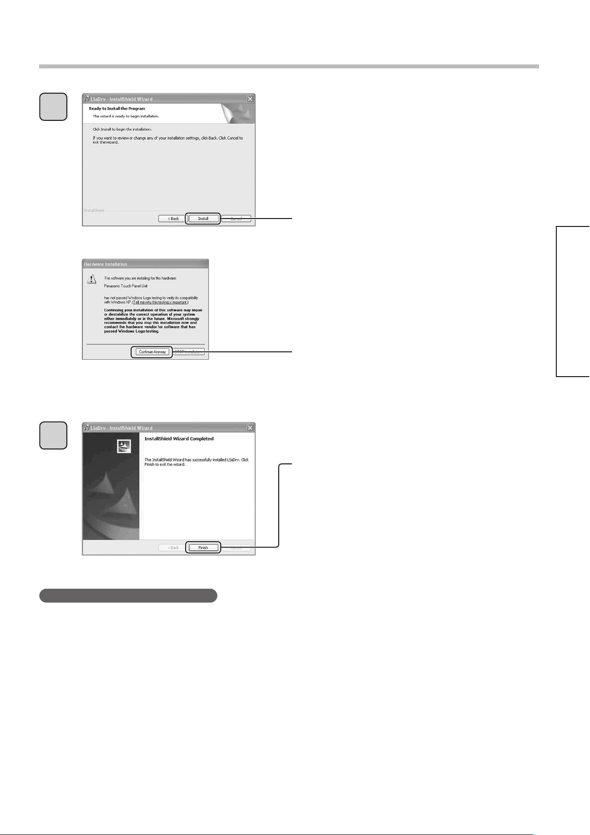
4
Driver Software Installation
Click this button.
Installation & Setup
A warning message similar to that at left may appear.
Click this button.
When the window at left appears, installation is
5
Note on reinstallation (upgrading)
If using Windows Vista, some specifications prevent users from operating files in the Program Files folder.
For that reason, some of the driver files in the Program Files folder are automatically copied to the Compatibility
folder from where they can be referenced.
The files in the Compatibility folder are not automatically deleted or updated even if the Driver software is
uninstalled and reinstalled.
If this Driver software is uninstalled and reinstalled, it starts up at the same settings that existed prior to being
uninstalled, unless the “lsdrv.ini” file in the Compatibility folder is deleted.
This occurs because the files in the Compatibility folder are referenced for settings.
To completely uninstall this Driver software, manually delete the files in the Compatibility folder.
* With Windows Vista and OSs of some specifications, the lsdrv.ini file is not overwritten when the Driver software
is upgraded if the update date of the lsdrv.ini file is newer than the upgrade data.
complete.
Click this button.
The “LSaDrv” folder is saved in [All Programs] under
the Start menu.
• If you select a complete installation, the Driver
software is automatically installed in the [Startup]
menu, therefore the Driver software starts up
when Windows starts up, making the touch panel
immediately operable.
15
 Loading...