

Panasonic SC-PT770 User Manual
Operating Instructions
1 ALL
2
4
1
As an ENERGY STAR Partner,
Panasonic has determined that
this product meets the ENERGY STAR
guidelines for energy efficiency.
®
®
[U.S.A.[and[Canada[
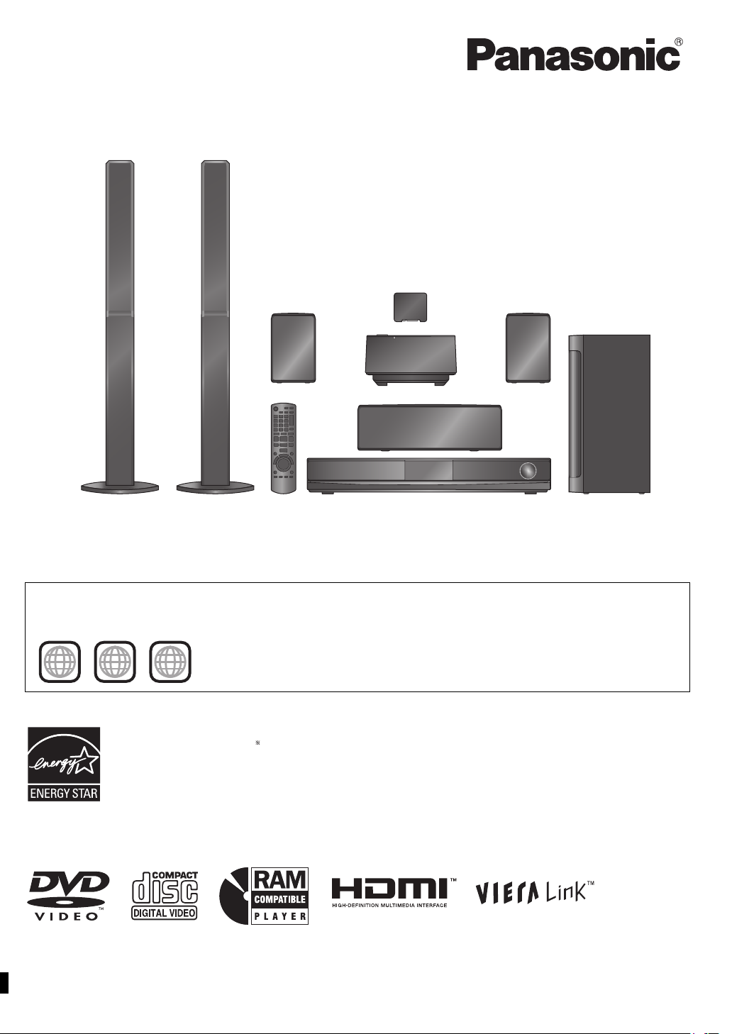
DVD Home Theater Sound System
Model No. SC-PT770
The illustrations shown may differ from your unit.
Region number
The player plays DVD-Video marked with labels containing the region number “1” or “ALL”.
Example:
§
For Canada only: The word “Participant” is used in place of the word
“Partner”.
Before connecting, operating or adjusting this product, please
read the instructions completely.
Please keep this manual for future reference.
If you have any questions contact
In the U.S.A. and Puerto Rico:
1-800-211-PANA (7262)
In Canada: 1-800-561-5505
[_P_] [_PC_]
RQTX0221-1P
Dear customer
(Inside of product)
(Side of product)
The laser product
label has not been
attached to products
for the U.S.A. and
Canada.
Thank you for purchasing this product. For optimum performance and
safety, please read these instructions carefully.
≥ These operating instructions are applicable to the model
SC-PT770 for a variety of regions.
≥ Unless otherwise indicated, illustrations in these operating
instructions are of the model for U.S.A. and Canada.
≥ Operations in these instructions are described mainly with the
remote control, but you can perform the operations on the main
unit if the controls are the same.
System
Main unit
Front speakers
Center speaker
Surround speakers
Subwoofer
Digital transmitter
Wireless system
SC-PT770
SA-PT770
SB-HF770
SB-HC470
SB-HS470
SB-HW560
SH-TR70A
SE-FX70
CAUTION!
THIS PRODUCT UTILIZES A LASER.
USE OF CONTROLS OR ADJUSTMENTS OR PERFORMANCE OF
PROCEDURES OTHER THAN THOSE SPECIFIED HEREIN MAY
RESULT IN HAZARDOUS RADIATION EXPOSURE.
DO NOT OPEN COVERS AND DO NOT REPAIR YOURSELF.
REFER SERVICING TO QUALIFIED PERSONNEL.
WARNING:
TO REDUCE THE RISK OF FIRE, ELECTRIC
SHOCK OR PRODUCT DAMAGE,
≥DO NOT EXPOSE THIS APPARATUS TO RAIN,
MOISTURE, DRIPPING OR SPLASHING AND
THAT NO OBJECTS FILLED WITH LIQUIDS,
SUCH AS VASES, SHALL BE PLACED ON THE
APPARATUS.
≥USE ONLY THE RECOMMENDED
ACCESSORIES.
≥DO NOT REMOVE THE COVER (OR BACK);
THERE ARE NO USER SERVICEABLE PARTS
INSIDE. REFER SERVICING TO QUALIFIED
SERVICE PERSONNEL.
CAUTION!
≥ DO NOT INSTALL OR PLACE THIS UNIT IN A BOOKCASE,
BUILT-IN CABINET OR IN ANOTHER CONFINED SPACE.
ENSURE THE UNIT IS WELL VENTILATED. TO PREVENT RISK
OF ELECTRIC SHOCK OR FIRE HAZARD DUE TO
OVERHEATING, ENSURE THAT CURTAINS AND ANY OTHER
MATERIALS DO NOT OBSTRUCT THE VENTILATION VENTS.
≥ DO NOT OBSTRUCT THE UNIT’S VENTILATION OPENINGS
WITH NEWSPAPERS, TABLECLOTHS, CURTAINS, AND
SIMILAR ITEMS.
≥ DO NOT PLACE SOURCES OF NAKED FLAMES, SUCH AS
LIGHTED CANDLES, ON THE UNIT.
≥ DISPOSE OF BATTERIES IN AN ENVIRONMENTALLY
FRIENDLY MANNER.
THE FOLLOWING APPLIES ONLY IN THE U.S.A. AND CANADA.
(For wireless system)
The following mark and symbols are located on bottom of the unit.
This product may receive radio interference caused by mobile
telephones during use. If such interference is apparent, please
increase separation between the product and the mobile telephone.
The socket outlet shall be installed near the equipment and easily
accessible.
The mains plug of the power supply cord shall remain readily
operable. To completely disconnect this apparatus from the AC
Mains, disconnect the power supply cord plug from AC receptacle.
For units with PX printed on the outer packaging
THIS UNIT IS INTENDED FOR USE IN MODERATE CLIMATES.
THE FOLLOWING APPLIES ONLY IN CANADA.
This device complies with RSS-210 of the IC Rules.
Operation is subject to the following two conditions:
(1) This device may not cause harmful interference,
(2) This device must accept any interference received, including
interference that may cause undesired operation of the device.
For wireless system
Product Identification Marking is located on the bottom of unit.
-If you see this symbol-
Information on Disposal in other Countries outside the
European Union
This symbol is only valid in the European Union.
If you wish to discard this product, please
contact your local authorities or dealer and ask
for the correct method of disposal.
CAUTION
RISK OF ELECTRIC SHOCK
DO NOT OPEN
CAUTION: TO REDUCE THE RISK OF ELECTRIC
RQTX0221
2
SHOCK, DO NOT REMOVE SCREWS.
NO USER-SERVICEABLE PARTS INSIDE.
REFER SERVICING TO QUALIFIED
SERVICE PERSONNEL.
The lightning flash with arrowhead symbol, within
an equilateral triangle, is intended to alert the user
to the presence of uninsulated “dangerous voltage”
within the product’s enclosure that may be of
sufficient magnitude to constitute a risk of electric
shock to persons.
The exclamation point within an equilateral triangle
is intended to alert the user to the presence of
important operating and maintenance (servicing)
instructions in the literature accompanying the
appliance.
THE FOLLOWING APPLIES ONLY IN THE U.S.A.
FCC Note:
This equipment has been tested and found to comply with the limits
for a Class B digital device, pursuant to Part 15 of the FCC Rules.
These limits are designed to provide reasonable protection against
harmful interference in a residential installation. This equipment
generates, uses and can radiate radio frequency energy and, if not
installed and used in accordance with the instructions, may cause
harmful interference to radio communications.
However, there is no guarantee that interference will not occur in a
particular installation. If this equipment does cause harmful
interference to radio or television reception, which can be determined
by turning the equipment off and on, the user is encouraged to try to
correct the interference by one or more of the following measures:
≥ Reorient or relocate the receiving antenna.
≥ Increase the separation between the equipment and receiver.
≥ Connect the equipment into an outlet on a circuit different from that
to which the receiver is connected.
≥ Consult the dealer or an experienced radio/TV technician for help.
FCC caution: To maintain compliance with FCC regulations, shielded
interface cables must be used with this equipment. Operation with
non-approved equipment or unshielded cables may result in
interference to radio and TV reception. Any changes or modifications
not approved by the party responsible for compliance could void the
user’s authority to operate this equipment.
This device complies with Part 15 of the FCC Rules.
Operation is subject to the following two conditions:
(1) This device may not cause harmful interference, and
(2) this device must accept any interference received, including
interference that may cause undesired operation.
Responsible Party:
Panasonic Corporation of North America
One Panasonic Way
Secaucus, NJ 07094
Support Contact:
Panasonic Consumer Electronics Company
Telephone No.: 1-800-211-PANA (7262)
WARNING:
To satisfy FCC RF exposure requirements for mobile transmitting
devices, a separation distance of 20 cm or more should be maintained
between the antenna of this device and persons during device
operation. To ensure compliance, operations at closer than this
distance is not recommended. The antenna used for this transmitter
must not be co-located in conjunction with any other antenna or
transmitter.
IMPORTANT SAFETY
INSTRUCTIONS
Read these operating instructions carefully before using the unit. Follow
the safety instructions on the unit and the applicable safety instructions
listed below. Keep these operating instructions handy for future reference.
1) Read these instructions.
2) Keep these instructions.
3) Heed all warnings.
4) Follow all instructions.
5) Do not use this apparatus near water.
6) Clean only with dry cloth.
7) Do not block any ventilation openings. Install in accordance with the
manufacturer’s instructions.
8) Do not install near any heat sources such as radiators, heat registers,
stoves, or other apparatus (including amplifiers) that produce heat.
9) \U.S.A.\and\Canada]
Do not defeat the safety purpose of the polarized or grounding-type
plug. A polarized plug has two blades with one wider than the other.
A grounding-type plug has two blades and a third grounding prong.
The wide blade or the third prong are provided for your safety. If the
provided plug does not fit into your outlet, consult an electrician for
replacement of the obsolete outlet.
10) Protect the power cord from being walked on or pinched particularly
at plugs, convenience receptacles, and the point where they exit from
the apparatus.
11) Only use attachments/accessories specified by the manufacturer.
12) Use only with the cart, stand, tripod, bracket, or
table specified by the manufacturer, or sold with the
apparatus. When a cart is used, use caution when
moving the cart/apparatus combination to avoid
injury from tip-over.
13) Unplug this apparatus during lightning storms or
when unused for long periods of time.
14) Refer all servicing to qualified service personnel. Servicing is
required when the apparatus has been damaged in any way, such as
power-supply cord or plug is damaged, liquid has been spilled or
objects have fallen into the apparatus, the apparatus has been
exposed to rain or moisture, does not operate normally, or has been
dropped.
Getting StartedPlaying DiscsOther OperationsReference
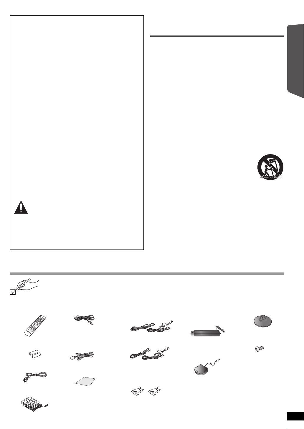
Accessories
Please check and identify the supplied accessories. Use numbers indicated in parentheses when asking for replacement parts.
(Product numbers correct as of December 2008. These may be subject to change.)
Only for U.S.A. and Puerto Rico:
To order accessories, refer to “Accessory Purchases (United States and Puerto Rico)” on page 36.
For other areas: To order accessories, call the dealer from whom you made your purchase.
∏ 1 Remote control
(N2QAYB000359)
∏ 2 Remote control
batteries
∏ 1 Video cable
(K2KA2BA00001)
∏ 1 AM loop antenna
(N1DAAAA00002)
∏ 1 FM indoor antenna
∏ 3 Speaker cables
∏ 1 Sheet of speaker
(RSA0007-M)
[REEX0860A-L (blue)]
[REEX0868A-L (gray)]
[REEX0858-L (green)]
cable stickers
∏ 2 AC power supply cords
[U.S.A.]and]]Canada]
(K2CB2CB00021)
[Others]
(K2CQ2CA00007)
\For\areas\except\U.S.A.\
[and\Canada]
∏ 2 AC plug adaptors
(K2DA42E00001)
2 Speaker stands
∏
(with cable)
[RYPX0386-KLJ (white)]
[RYPX0386-KRJ (red)]
∏ 1 Auto speaker setup
microphone
(L0CBAB000125)
∏ 2 Bases
(RYPX0389-KJ)
∏ 8 Screws
(XTN5+10FFJK)
RQTX0221
3
Glossary
EST. 1924
Decoder
A decoder restores the coded audio signals on DVDs to normal. This is
called decoding.
Dolby Digital
This is a method of coding digital signals developed by Dolby
Laboratories. Apart from stereo (2-channel) audio, these signals can also
be 5.1-channel sound.
DTS (Digital Theater Systems)
This surround system is used in many movie theaters around the world.
Getting StartedPlaying DiscsOther OperationsReference
There is good separation between the channels, so realistic sound effects
are possible.
Dynamic range
Dynamic range is the difference between the lowest level of sound that
can be heard above the noise of the equipment and the highest level of
sound before distortion occurs.
Frame still and field still
Frames are the still pictures that go together to make a moving picture.
There are about 30 frames shown each second.
One frame is made up of two fields. A regular TV shows these fields one
after the other to create frames.
A still is shown when you pause a moving picture. A frame still is made up
of two alternating fields, so the picture may appear blurred, but overall
quality is high.
A field still is not blurred, but it has only half the information of a frame still
so picture quality is lower.
HDMI (High-Definition Multimedia Interface)
HDMI is a next-generation digital interface for consumer electronic
products. Unlike conventional connections, it transmits uncompressed
digital video and audio signals on a single cable. This unit supports highdefinition video output (720p, 1080i, 1080p) from the HDMI AV OUT
terminal. To enjoy high-definition video, a high-definition compatible TV is
required.
I/P/B
MPEG 2, the video compression standard adopted for use with
DVD-Video, codes frames using these 3 picture types.
I: Intra coded picture
This picture has the best quality and is the best to use when adjusting
the picture.
P: Predictive coded picture
This picture is calculated based on past I- or P-pictures.
B: Bidirectionally-predictive coded picture
This picture is calculated by comparing past and future I- and
P-pictures so it has the lowest volume of information.
JPEG (Joint Photographic Experts Group)
This is a system used for compressing/decoding color still pictures. The
benefit of JPEG is less deterioration in picture quality considering the
degree of compression.
Linear PCM (pulse code modulation)
These are uncompressed digital signals, similar to those found on CDs.
MP3 (MPEG Audio Layer 3)
An audio compression method that compresses audio to approximately
one tenth of its size without any considerable loss of audio quality.
Playback control (PBC)
If a Video CD has playback control, you can select scenes and
information with menus.
Progressive/Interlaced
NTSC, the video signal standard, has 480 interlaced (i) scan lines,
whereas progressive scanning uses twice the number of scan lines. This
is called 480p.
Using progressive output, you can enjoy the high-resolution video
recorded on media such as DVD-Video.
Your TV must be compatible to enjoy progressive video.
Sampling frequency
Sampling is the process of converting the heights of sound wave (analog
signal) samples taken at set periods into digits (digital encoding).
Sampling frequency is the number of samples taken per second, so larger
numbers mean more faithful reproduction of the original sound.
WMA
WMA is a compression format developed by Microsoft Corporation. It
achieves the same sound quality as MP3 with a file size that is smaller
than that of MP3.
Selecting fine audio equipment such as the
unit you’ve just purchased is only the start of
your musical enjoyment. Now it’s time to
consider how you can maximize the fun and
excitement your equipment offers. This
manufacturer and the Electronic Industries
Association’s Consumer Electronics Group
want you to get the most out of your
equipment by playing it at a safe level. One
that lets the sound come through loud and
clear without annoying blaring or distortion
—and, most importantly, without affecting
your sensitive hearing.
RQTX0221
4
Listening caution
We recommend that you avoid prolonged
exposure to excessive noise.
Sound can be deceiving. Over time your
hearing “comfort level” adapts to higher
volumes of sound. So what sounds “normal”
can actually be loud and harmful to your
hearing.
Guard against this by setting your equipment
at a safe level BEFORE your hearing adapts.
To establish a safe level:
≥ Start your volume control at a low setting.
≥ Slowly increase the sound until you can
hear it comfortably and clearly, and without
distortion.
Once you have established a comfortable
sound level:
≥ Set the dial and leave it there.
Taking a minute to do this now will help to
prevent hearing damage or loss in the future.
After all, we want you listening for a lifetime.

TABLE OF CONTENTS
Getting Started
IMPORTANT SAFETY INSTRUCTIONS. . . . . . . . . . . . . . .3
Accessories . . . . . . . . . . . . . . . . . . . . . . . . . . . . . . . . . . . .3
Glossary . . . . . . . . . . . . . . . . . . . . . . . . . . . . . . . . . . . . . . .4
Quick Start Guide
step 1 Assembling the front speakers . . . . . . . . . . . 6
step 2 Positioning . . . . . . . . . . . . . . . . . . . . . . . . . . . 7
step 3 Connections . . . . . . . . . . . . . . . . . . . . . . . . . . 8
Digital transmitter connection . . . . . . . . . . . . . . . .8
Speaker connections . . . . . . . . . . . . . . . . . . . . . .8
Audio and video connections . . . . . . . . . . . . . . . .9
Radio antenna connections . . . . . . . . . . . . . . . .10
step 4 AC power supply cord connections . . . . . . 11
step 5 Preparing the wireless system . . . . . . . . . . 11
step 6 Preparing the remote control . . . . . . . . . . . 11
step 7
Playing Discs
Basic play . . . . . . . . . . . . . . . . . . . . . . . . . . . . . . . . . . . . .18
Other modes of play. . . . . . . . . . . . . . . . . . . . . . . . . . . . .20
SMART SETUP. . . . . . . . . . . . . . . . . . . . . . 12
Using the main unit. . . . . . . . . . . . . . . . . . . . . . . . . . . . . . . 18
Using the remote control. . . . . . . . . . . . . . . . . . . . . . . . . . . 19
Playing CDs sequentially (CD Mode) . . . . . . . . . . . . . . . . . 20
Repeat play. . . . . . . . . . . . . . . . . . . . . . . . . . . . . . . . . . . . . 20
Program and Random play. . . . . . . . . . . . . . . . . . . . . . . . . 20
Setting up the radio. . . . . . . . . . . . . . . . . . . . . . . . . . . . . 13
Presetting stations automatically . . . . . . . . . . . . . . . . . . . . 13
Confirming the preset channels. . . . . . . . . . . . . . . . . . . . . 13
Manual tuning . . . . . . . . . . . . . . . . . . . . . . . . . . . . . . . . . . 13
Selecting the playback source. . . . . . . . . . . . . . . . . . . . 15
Selecting the source from the START menu . . . . . . . . . . . 15
Selecting the source by the remote control . . . . . . . . . . . . 15
Enjoying sound from all
speakers and various sound
effects
Enjoying surround sound effects . . . . . . . . . . . . . . 16
Selecting sound mode . . . . . . . . . . . . . . . . . . . . . . . 16
Whisper-mode Surround . . . . . . . . . . . . . . . . . . . . . 16
Adjusting the speaker output level manually . . . . 17
Using navigation menus . . . . . . . . . . . . . . . . . . . . . . . . . 21
Playing data discs . . . . . . . . . . . . . . . . . . . . . . . . . . . . . . . 21
Playing RAM and DVD-R/-RW (DVD-VR) discs . . . . . . . . 21
Using on-screen menus . . . . . . . . . . . . . . . . . . . . . . . . . 22
Getting StartedPlaying DiscsOther OperationsReference
Other Operations
Using the VIERA Link
One touch play . . . . . . . . . . . . . . . . . . . . . . . . . . . . . . . . . . 24
Auto input switching . . . . . . . . . . . . . . . . . . . . . . . . . . . . . .24
Power off link . . . . . . . . . . . . . . . . . . . . . . . . . . . . . . . . . . . 24
Speaker control. . . . . . . . . . . . . . . . . . . . . . . . . . . . . . . . . . 25
VIERA Link Control only with TV’s remote control
(for “HDAVI Control 2 or later”) . . . . . . . . . . . . . . . . . . . . 25
TM
“HDAVI ControlTM” . . . . . . . . . .24
Reference
Speaker installation options . . . . . . . . . . . . . . . . . . . . . .27
Changing the player settings . . . . . . . . . . . . . . . . . . . . .28
Discs that can be played . . . . . . . . . . . . . . . . . . . . . . . . .30
Maintenance . . . . . . . . . . . . . . . . . . . . . . . . . . . . . . . . . . . . 31
Product Service . . . . . . . . . . . . . . . . . . . . . . . . . . . . . . . .31
Troubleshooting guide . . . . . . . . . . . . . . . . . . . . . . . . . .32
Using the iPod . . . . . . . . . . . . . . . . . . . . . . . . . . . . . . . . . 26
Specifications . . . . . . . . . . . . . . . . . . . . . . . . . . . . . . . . . 34
Limited Warranty
(ONLY FOR U.S.A. AND PUERTO RICO) . . . . . . . . . . 36
Limited Warranty (ONLY FOR CANADA). . . . . . . . . . . . 37
Control reference guide . . . . . . . . . . . . . . . . . . . . . . . . . 38
RQTX0221
5
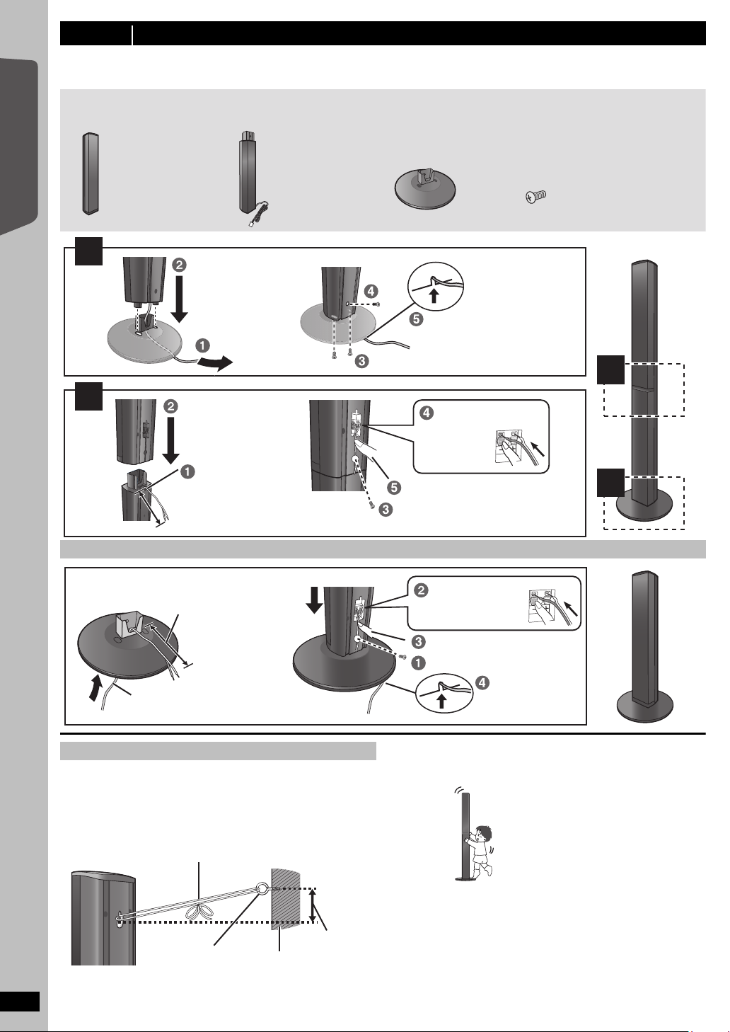
step 1 Assembling the front speakers
Make sure you have all the indicated components before starting assembly, setup, and connection.
≥ Keep the screws out of reach of children to prevent swallowing.
≥ For optional wall mount, refer to page 27.
2 Bases 8 Screws2 Front speakers 2 Stands
(with cable)
1
2
2
1
Tighten securely.
Slide into the groove.
Position the cable
between the ridges.
Tighten securely.
Press into the groove.
Insert the wire fully.
i: White
j: Blue
Push!
Leave about 120 mm (4
23
/32z)
Leave about
120 mm (4
23
/32z)
You can remove and use the
cable from the stand. To reattach
the cable, refer to page 27.
Insert the wire fully.
i: White
j: Blue
Push!
Tighten securely.
Press into the groove.
Thread the speaker cable through
the base.
Attach the speaker.
Slide into
the groove.
String (not included)
Thread from the wall to the speaker and tie tightly.
Rear of the
speaker
Wall
Approx.
150 mm
(5
29
/32z)
Screw eye
(not included)
DO
NOT
Preparation
≥ To prevent damage or scratches, lay down a soft cloth to assemble speakers.
≥ For assembly, use a Phillips-head screwdriver (not included).
Getting Started
Quick Start Guide
Speaker assembly option
6
Preventing the speakers from falling
≥ You will need to obtain the appropriate screw eyes to match the walls
or pillars to which they are going to be fastened.
≥ Consult a qualified housing contractor concerning the appropriate
procedure when attaching to a concrete wall or a surface that may not
have strong enough support. Improper attachment may result in
damage to the wall or speakers.
RQTX0221
Caution
Do not stand on the base. Be cautious when children are near.
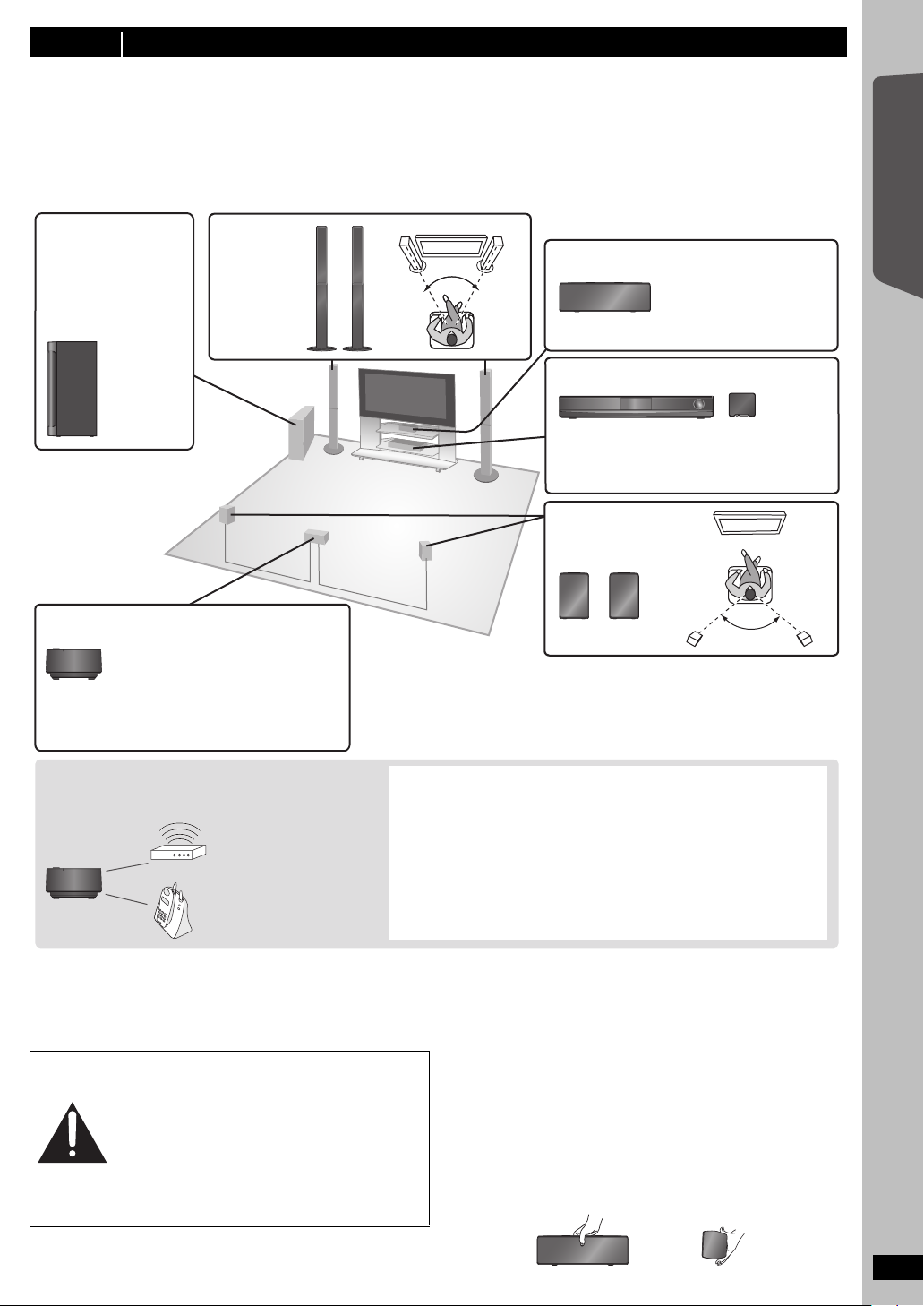
step 2 Positioning
120°
60°60º
To allow for proper ventilation and to maintain
good airflow around the main unit, position it with
at least 5 cm (2q) of space on all sides.
Main unit Digital transmitter
§
Wireless system
§
≥ Place the wireless system within
approximately 15 m (47 ft) from the
main unit, and in a horizontal position
with the top panel faced upward.
≥ To allow for proper ventilation and to
maintain good airflow around the
wireless system, position it with at least
5cm (2q) of space on all sides.
To avoid interference, maintain the following
distances between the wireless system and other
electronic devices that use the same radio frequency
(2.4 GHz band).
The wireless system will automatically seek a clear channel if any of these
other devices interfere with its communication. When this happens, the
wireless link indicator (“ [W1] ”) flashes on the main unit, and there is a brief
interruption in audio coming from the surround speakers.
This is the normal operation of the product working to assure the best
possible performance of your home theater system.
If the interference persists, try moving the other devices to another location
outside the range of the wireless system or move the wireless system
nearer to the main unit.
Wireless LAN:
approx. 2 m (6
1
/2 ft)
Cordless phone and
other electronic devices:
approx. 2 m (6
1
/2 ft)
Center speaker
Put on a rack or shelf.
Vibration caused by the
speaker can disrupt the
picture if it is placed directly
on the TV.
Wireless
system
Subwoofer
Place to the right or left
of the TV, on the floor or
a sturdy shelf so that it
will not cause vibration.
Leave about 30 cm
(11
13
/16q) from the TV.
Front
speakers
Surround speakers
§
Do not use the wireless system or the digital
transmitter in a metal cabinet or bookshelf.
DO
DO
NOT
How you set up your speakers can affect the bass and the sound field.
Note the following points:
≥ Place speakers on flat secure bases.
≥ Placing speakers too close to floors, walls, and corners can result in excessive bass. Cover walls and windows with thick curtains.
[Note]
Keep your speakers at least 10 mm (
Setup example
Place the front, center, and surround speakers at approximately the same distance from the seating position. Using “Auto speaker setup” (B 12) is a
convenient way to get the ideal surround sound from your speakers when you are unable to place them. The angles in the diagram are approximate.
13
/32z) away from the system for proper ventilation.
Getting Started
Quick Start Guide
If irregular coloring occurs on your TV
The center speaker is designed to be used close to a TV, but the picture
may be affected with some TVs and setup combinations.
If this occurs, turn the TV off for about 30 minutes.
The demagnetizing function of the TV should correct the problem. If it
persists, move the speakers further away from the TV.
Caution
≥ The main unit and supplied speakers are to be
used only as indicated in this setup. Failure to
do so may lead to damage to the amplifier and/or
the speakers, and may result in the risk of fire.
Consult a qualified service person if damage has
occurred or if you experience a sudden change
in performance.
≥ Do not attempt to attach these speakers to walls
using methods other than those described in
this manual.
Notes on speaker use
≥Use only supplied speakers
Using other speakers can damage the unit, and sound quality will be
negatively affected.
≥ You can damage your speakers and shorten their useful life if you play
sound at high levels over extended periods.
≥ Reduce the volume in the following cases to avoid damage:
– When playing distorted sound.
– When the speakers are reverberating due to a record player, noise
from FM broadcasts, or continuous signals from an oscillator, test
disc, or electronic instrument.
– When adjusting the sound quality.
– When turning the unit on or off.
Caution
Do not touch the front netted area of the speakers. Hold by the sides.
e.g. Center speaker
RQTX0221
7
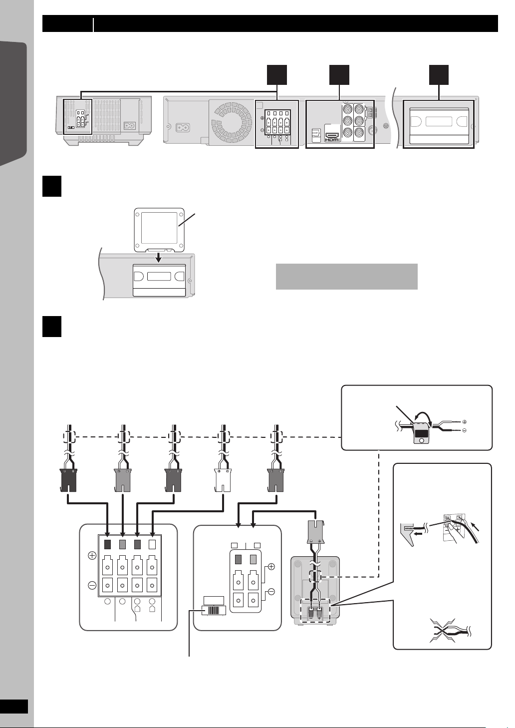
step 3 Connections
CENTERSUBWOOFER FRONT
6 5 2 1
L
R
TRANSMITTER
DIGITAL
Do not insert or remove the digital
transmitter while the main unit is on.
Digital transmitter
Insert fully until you hear a click.
Main unit
CENTERSUBWOOFER FRONT
6 5 2 1
L
R
WHITE
FRONT
(L)
GRAY
SURROUND
(R)
BLUE
SURROUND
(L)
RED
FRONT
(R)
GREEN
CENTER
PURPLE
SUBWOOFER
DO
NOT
Lch
SURROUND
3
Push!
SPEAKERS
ENCEINTES
LS / RB LB / RS
SURROUND
AMBIOPHONIQUES
SURR
L
SIDERSIDE
Surround speaker (R)
Wireless systemMain unit
e.g. Surround speaker (L)
Speaker cable sticker (included)
≥ Be careful not to cross
(short circuit) or reverse
the polarity of the
speaker wires as doing
so may damage the
speakers.
Insert the wire fully, taking
care not to insert beyond
the wire insulation.
i: White
j: Blue
Surround selector
The surround selector switch must
be set in the center position.
Turn off all equipment before connection and read the appropriate operating instructions.
Do not connect the AC power supply cord until all other connections are complete.
Getting Started
Main unitWireless system
Digital transmitter connection
1
Quick Start Guide
Speaker connections
2
Setup example
Pay attention to the type of speaker and the connector color when you place the speakers.
Connect to the terminals of the same color.
Use of the speaker cable stickers is convenient when making cable connections.
2
3 1
AUX
Y
L
B
P
P
R
COMPONENT
VIDEO OUT
R
VIDEO OUT
OPTICAL
AV OUT
IN
DIGITAL
TRANSMITTER
RQTX0221
8
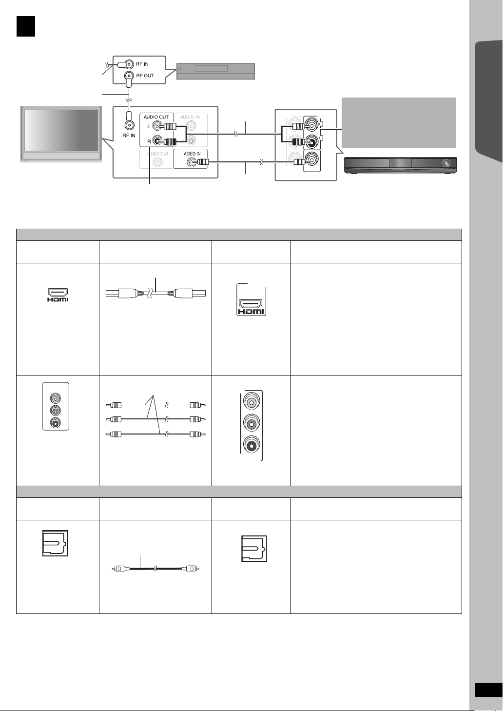
Audio and video connections
Y
P
B
P
R
COMPONENT
VIDEO OUT
VIDEO OUT
AUX
L
R
RF cable (not included)
TV (not included)
Set top box (STB) or VCR
(not included)
Video cable
(included)
Audio cable
(not included)
Main unit
To your cable TV
service or TV antenna
You can enjoy the audio from your
TV, cable or satellite STB, or your
VCR through this home theater
system by connecting to the AUX
terminal.
Select “AUX” as the source (B 15).
Refer to the operating instructions for the TV, cable
or satellite STB, or VCR for the settings necessary
to output its audio from the AUDIO OUT terminal to
your home theater system.
AV O UT
Video cables
OPTICAL OUT
Optical digital audio cable
3
Basic setup example
Getting Started
Other video connections
TV terminal
AV IN
COMPONENT
VIDEO IN
Y
PB
PR
All Panasonic TVs that
have 480p input
connectors are
compatible. Consult the
manufacturer if you have
another brand of TV.
Cable required
(not included)
HDMI cable
[Note]
≥ Non-HDMI-compliant cables
cannot be utilized.
≥ It is recommended that you use
Panasonic’s HDMI cable.
Recommended part number:
RP-CDHG15 (1.5 m/4.9 ft),
RP-CDHG30 (3.0 m/9.8 ft),
RP-CDHG50 (5.0 m/16.4 ft), etc.
Main unit terminal Features
[\\\\\\\\\\\HDMI\\\\\\\\\\\] This connection provides the best picture quality.
≥ Set “VIDEO PRIORITY” to “ON” (B 29, HDMI
menu).
≥ Set “VIDEO FORMAT” in Menu 4 (HDMI) (B 23).
VIERA Link “HDAVI Control”
If your Panasonic TV is VIERA Link compatible, you
can operate your TV synchronizing with home theater
operations or vice versa (B 24, Using the VIERA
TM
“HDAVI ControlTM”).
Link
≥ Make the audio connection (B above) when you use
VIERA Link “HDAVI Control” function.
[COMPONENT\VIDEO]
Y
P
B
P
R
COMPONENT
VIDEO OUT
≥ Connect to terminals
of the same color.
This connection provides a much purer picture than
the VIDEO OUT terminal.
≥ After making this connection, select “DARKER” from
the “BLACK LEVEL” in the VIDEO menu (B 28).
To enjoy progressive video
≥ Connect to a progressive output compatible TV.
– Set “VIDEO OUT (I/P)” in VIDEO menu to
“PROGRESSIVE” and then follow the instructions
on the menu screen (B 28).
Other audio connection
TV or external
equipment terminal
Cable required
(not included)
≥ Do not bend sharply when
connecting.
Main unit terminal Features
[\\\\\\OPTICAL\IN\\\\\\] This is the preferred connection for best sound and
true surround sound.
This unit can decode the surround signals received
from your TV, cable or satellite STB. Refer to the
OPTICAL
IN
[Note]
≥ Do not make the video connections through the VCR.
Due to copy guard protection, the picture may not be displayed properly.
≥ Only one video connection is required. Choose one of the video connections above depending on your TV.
≥ If you have various sound sources (such as Blu-ray player, DVD recorder, VCR, etc.), connect them to the available inputs on the TV and the TV
output should then be connected to the AUX or OPTICAL IN terminal of the main unit.
operating instructions for the TV, cable or satellite STB
for the settings necessary to output its audio from the
digital audio output to your home theater system. Only
Dolby Digital and PCM can be played with this
connection.
≥ After making this connection, make settings to suit
the type of audio from your digital equipment (B 15).
Quick Start Guide
RQTX0221
9
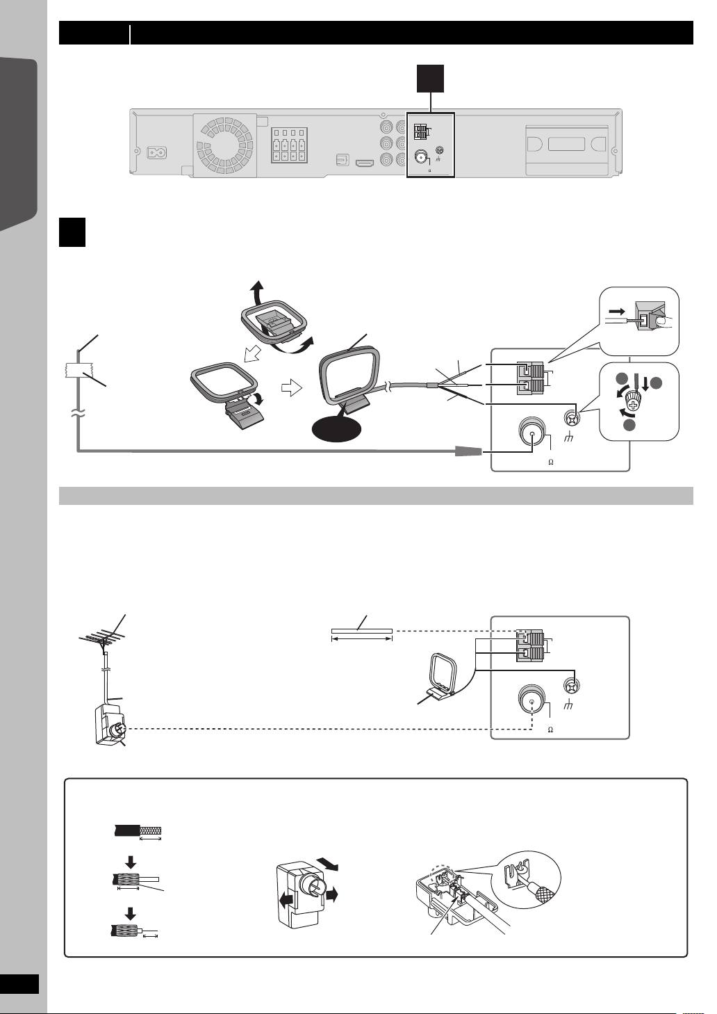
step 3 Connections (continued)
AM ANT
EXT
LOOP
FM ANT
(75 )
LOOP
ANT GND
Main unit
4
AM ANT
EXT
LOOP
FM ANT
(75 )
LOOP
ANT GND
Main unit
Push!
Click!
Red
White
Black
Adhesive
tape
1
3
2
[AM\loop\antenna]
(included)
Stand the antenna up on its base.
Place the antenna where reception is best.
[FM\indoor\antenna]
(included)
Affix this end of the antenna where
reception is best.
Leave the AM loop
antenna connected.
AM outdoor antenna
[Using a vinyl wire (not included)]
Run a piece of vinyl wire horizontally across a
window or other convenient location.
5.0 m to 12 m
(16 ft to 39 ft)
FM outdoor antenna
[Using a TV antenna (not included)]
The antenna should be installed by a
competent technician.
75 ≠ coaxial cable
§
(not included)
\U.S.A.\and\Canada]
Antenna plug (not included)
Use outdoor antenna if FM/AM radio reception is poor.
≥ Disconnect the antenna when the unit is not in use.
≥ Do not use the outdoor antenna during an electrical storm.
1 Remove a piece of the outer
vinyl insulator.
2 Carefully pull the tabs apart
to remove the cover.
3 Install the coaxial cable.
Clamp the cable conductor, and
wind it around so that it does not
contact anything else.
7mm (
9
/32z)
Peel back
4 Attach the cover.
Clamp with pliers.
10 mm (
13
/32z)
§
Rework your outdoor antenna’s 75 ≠ coaxial cable as follows.
10 mm (
13
/32z)
Main unit
Getting Started
Radio antenna connections
4
≥ Keep loose antenna cables away from other wires and cables.
Quick Start Guide
Using an FM/AM outdoor antenna (optional)
10
RQTX0221
AM ANT
EXT
LOOP
FM ANT
(75 )
LOOP
ANT GND
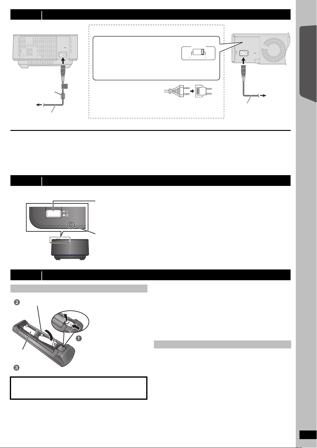
step 4 AC power supply cord connections
AC IN
AC IN
110 127V 220 240V
VOLT ADJ
To
household
AC outlet
Main unitWireless system
AC power supply cord
(included)
Before connecting the AC power
supply cord
Set the voltage.
Use a flat-head screwdriver to move the
voltage selector to the appropriate position
for the area in which this system is used.
Ferrite core
≥ If the AC plug does not fit
your household AC outlet
Use the AC plug adaptor
(included).
If it still does not fit, contact an electrical
parts distributor for assistance.
AC power
supply cord
(included)
To
household
AC outlet
[For\areas\except\U.S.A.[and\Canada]
WIRELESS LINK indicator
Red: The wireless system is on and the wireless link is deactivated.
Green: The wireless system is on and the wireless link is activated.
(“ [W1] ” is also displayed on the main unit’s display.)
Press [POWER C I, BÍ] on the wireless system.
Unit on/off button [POWER C I, BÍ]
Use this button to turn the wireless system on and off.
C I: The wireless system is on.
BÍ: The wireless system is off.
Wireless system
Getting Started
Conserving power
The main unit and the wireless system consume a small amount of
power when they are turned off (\U.S.A.[and\Canada] main unit: approx.
0.1 W, wireless system: approx. 0.2 W, \Others] main unit: approx. 0.2 W,
wireless system: approx. 0.3 W). To save power when they are not to be
used for a long time, unplug them from the household AC outlet.
You will need to reset some memory items after plugging in the main
unit.
step 5 Preparing the wireless system
Turn on the wireless system after all connections are complete.
WIRELESS LINK
POWER
step 6 Preparing the remote control
Batteries
Insert so the poles ( and ) match those in the remote control.
Press in and lift up.
R6/LR6, AA
Replace the cover.
CAUTION
Danger of explosion if battery is incorrectly replaced. Replace only
with the same or equivalent type recommended by the manufacturer.
Dispose of used batteries according to the manufacturer’s instructions.
≥ Use alkaline or manganese batteries.
≥ Do not heat or expose to flame.
≥ Do not leave the battery(ies) in an automobile exposed to direct
sunlight for a long period of time with doors and windows closed.
[Note]
The included AC power supply cords are for use with the main unit and
wireless system only. Do not use them with other equipment. Also, do
not use cords for other equipment with the main unit or wireless system.
Do not:
≥ mix old and new batteries.
≥ use different types of batteries at the same time.
≥ take apart or short circuit.
≥ attempt to recharge alkaline or manganese batteries.
≥ use batteries if the covering has been peeled off.
Mishandling of batteries can cause electrolyte leakage which can
severely damage the remote control.
Remove the batteries if the remote control is not going to be used for a
long period of time. Store in a cool, dark place.
Use
Aim at the remote control signal sensor (B 39), avoiding obstacles, at a
maximum range of 7 m (23 ft) directly in front of the unit.
Quick Start Guide
RQTX0221
11
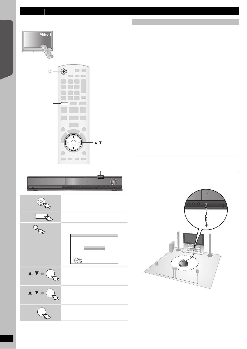
step 7 SMART SETUP
OK
DVD
OK
DVD
(Main unit only)
SET
RETURN
Smart setup
Would you like to start smart
setup?
Yes
No
OK
SETUP MIC
The Smart setup screen assists you in making necessary
settings.
Preparation
Turn on your TV and select the appropriate
video input mode (e.g. VIDEO 1, AV 1, HDMI,
etc.) to suit the connections to this unit.
≥ To change your TV’s video input mode, refer
to its operating instructions.
≥ This remote control can perform some basic
TV operations (B 38).
Getting Started
Quick Start Guide
SMART SETUP
Smart setup settings
≥Language
Select the language used on menu screen.
≥TV aspect
Select the aspect to suit your TV.
≥Speaker check
Listen to speaker output to confirm speaker connections.
≥Auto speaker setup
Adjust the speaker output level automatically. (B below)
≥Speaker output
Make surround sound setting for speaker output.
≥TV audio
Select the audio input connection from your TV.
For AUX connection (B 9): Select “AUX”.
For OPTICAL IN connection (B 9): Select “DIGITAL IN”.
This will be the TV audio setting for VIERA Link “HDAVI Control”. (B24)
[Note]
≥ If this unit is connected to a “HDAVI Control 3 or later” compatible TV
via HDMI cable, the menu language and TV aspect information will be
retrieved via VIERA Link.
≥ If this unit is connected to a “HDAVI Control 2” compatible TV via
HDMI cable, the menu language information will be retrieved via
VIERA Link.
≥ Settings in the Smart setup can also be changed in the player settings
[e.g. language, TV aspect, speaker level and TV audio (B 28)].
∫ Adjusting the speaker output level automatically:
Auto speaker setup
The speaker level settings can be optimized to accommodate your
room’s listening conditions so that you can enjoy the ideal surround
sound experience.
Keep as quiet as possible during the Auto speaker setup. Loud
voices, air-conditioning noise, or excessive wind may lead to incorrect
settings. The speakers output loud test signals during setup.
≥ Place the Auto speaker setup microphone at actual seating position.
(At ear level when seated.)
≥ The test signal is output from each speaker.
1
2
3
4
5
6
RQTX0221
12
DVD
SMART SETUP
OK
OK
Turn on the unit.
≥ When the Smart setup screen appears
automatically, skip step 2 and 3.
Select “DVD/CD”.
Show the Smart setup.
e.g.
Select “Yes”.
Follow the messages and
make the settings.
(B right, Smart setup settings)
Finish Smart setup.
[Note]
Auto speaker setup can be activated through Smart setup only.
 Loading...